

Page 1

6000i CNC Technical Manual
September 2008
Ve 04
627787-21 · 9/2008 · KS · Printed in USA · Subject to change without notice
www.anilam.com
Page 2

Page 3

CNC Technical Manual
P/N 627787-21 - Warranty
Warranty
ANILAM® is a brand manufactured and sold by Acu-Rite Companies Inc. Acu-Rite Companies
Inc. warrants its products to be free from defects in material and workmanship for one (1) year
from date of installation. At our option, we will repair or replace any defective product upon
prepaid return to our factory.
This warranty applies to all products when used in a normal industrial environment. Any
unauthorized tampering, misuse or neglect will make this warranty null and void.
Under no circumstances will Acu-Rite Companies Inc., any affiliate, or related company assume
any liability for loss of use or for any direct or consequential damages.
The foregoing warranties are in lieu of all other warranties expressed or implied, including, but
not limited to, the implied warranties of merchantability and fitness for a particular purpose.
The information in this manual has been thoroughly reviewed and is believed to be accurate.
ACU-RITE® Companies Inc. reserves the right to make changes to improve reliability, function,
or design without notice. ACU-RITE Companies Inc. assumes no liability arising out of the
application or use of the product described herein.
ANILAM® and ACU-RITE® are registered trademarks of ACU-RITE Companies Inc.
© Copyright 2008 ACU-RITE Companies Inc.
All rights reserved. Subject to change without notice. iii
September 2008
Page 4

Page 5

CNC Technical Manual
P/N 627787-21 - Contents
Section 1 - Introduction
General Information....................................................................................................... 1 – 1
System Overview ........................................................................................................... 1 – 1
Product Designations.................................................................................................... 1 – 2
Meaning of the Symbols Used in this Manual............................................................. 1 – 2
6000i Overview............................................................................................................... 1 – 3
Software Update Procedure.......................................................................................... 1 – 4
Section 2 - Mounting and Electrical Installation
General Information....................................................................................................... 2 – 1
Safety Precautions ......................................................................................................... 2 – 1
Degrees of Protection .................................................................................................... 2 – 2
Electromagnetic Compatibility ........................................................................................ 2 – 2
Handling the HDR Hard Disk and SIK ........................................................................... 2 – 3
Shipping Brace of the HDR ............................................................................................ 2 – 3
Installing/Removing the HDR and SIK ........................................................................... 2 – 4
Environmental Conditions ............................................................................................. 2 – 5
Heating and Cooling ....................................................................................................... 2 – 5
Humidity ......................................................................................................................... 2 – 6
Mechanical Vibration ...................................................................................................... 2 – 6
Mounting Considerations............................................................................................... 2 – 7
MC, CC, Inverter, and Amplifier Power Module ............................................................. 2 – 7
Shipping Brace of the Hard Disk .................................................................................... 2 – 8
Installing and Removing the Hard Drive and SIK ........................................................... 2 – 8
Display ........................................................................................................................... 2 – 8
Connection Overview .................................................................................................... 2 – 9
Connecting MC 400 and CC 600 with Maximum Six Control Loops .............................. 2 – 9
Cable and Basic Circuit Overview ................................................................................ 2 – 10
MC 400 and CC 600 Pinouts........................................................................................ 2 – 10
Position Control for Encoders .......................................................................................2 – 11
Encoders for Speed Control ......................................................................................... 2 – 12
Touch Probe ................................................................................................................. 2 – 13
PWM Connection to Axis/Spindle Motors .....................................................................2 – 22
CNC Power Supply and Control Signals ...................................................................... 2 – 23
Control-Is-Ready Signal ............................................................................................... 2 – 24
Power Supply for PLC Outputs ..................................................................................... 2 – 24
Buffer Battery ................................................................................................................2 – 26
Analog Nominal Value Output ...................................................................................... 2 – 27
Analog Input ................................................................................................................. 2 – 28
Switching Inputs 24 VDC (PLC) ....................................................................................2 – 30
Switching Outputs 24 VDC (PLC) ................................................................................ 2 – 34
Flat Panel Display ........................................................................................................ 2 – 38
Manual Panel ............................................................................................................... 2 – 40
CNC Keyboard ............................................................................................................. 2 – 42
I/O Module Connection ................................................................................................ 2 – 43
Data Interfaces ............................................................................................................. 2 – 46
USB Interface ............................................................................................................... 2 – 49
Drive Controller Enable ................................................................................................2 – 50
PLC Input/Output Units ................................................................................................ 2 – 51
I/O Module and I/O Expansion Base Module P/N Summary....................................... 2 – 51
Handwheel Input ............................................................................................................ 2 – 52
RM 500 Remote Handwheel ........................................................................................ 2 – 53
RM 300 Panel-Mounted Handwheel ............................................................................ 2 – 56
All rights reserved. Subject to change without notice. v
September 2008
Page 6

CNC Technical Manual
P/N 627787-21 - Contents
PM 350 Panel-Mounted Handwheel .............................................................................2 – 57
Console FP 6000i ......................................................................................................... 2 – 60
Manual Panel MP 6000M and MP 6001M.................................................................... 2 – 61
Section 3 - Machine Parameters
General Information....................................................................................................... 3 – 1
The Configuration Editor............................................................................................... 3 – 2
Calling the Configuration Editor ......................................................................................3 – 3
Machine Parameter Screen ............................................................................................3 – 5
Entering and Editing Machine Parameters ..................................................................... 3 – 7
Managing Configuration Files .......................................................................................3 – 13
Sort File Content .......................................................................................................... 3 – 13
Table View ................................................................................................................... 3 – 14
Access Rights .............................................................................................................. 3 – 14
Update Rules ...............................................................................................................3 – 16
Remove Syntax Error ................................................................................................... 3 – 17
Reset Update Version .................................................................................................. 3 – 17
Backup of Parameters .................................................................................................. 3 – 18
Allocation of Configuration Data................................................................................ 3 – 19
Setup of a Parameter File............................................................................................ 3 – 22
MP Subfiles................................................................................................................... 3 – 23
Syntax of MP Subfile .................................................................................................... 3 – 23
Activating MP Subfiles ..................................................................................................3 – 23
Displaying/Editing Data Records in the Configuration Editor ....................................... 3 – 26
MP Change List in the Configuration Editor ................................................................. 3 – 28
MP Movement Monitoring ............................................................................................ 3 – 29
MP Programming Station Mode ................................................................................... 3 – 29
Read or Change Machine Parameters via a PLC Module......................................... 3 – 31
Overview of the Machine Parameters of the 6000i ................................................... 3 – 35
System ......................................................................................................................... 3 – 35
Channels ......................................................................................................................3 – 87
Axes ........................................................................................................................... 3 – 104
KeySynonym ..............................................................................................................3 – 131
Section 4 - Modules and PLC Operands
Overview of Modules..................................................................................................... 4 – 1
Overview of the PLC Operands .................................................................................... 4 – 6
PLC Operands of the “General Data” Group ..................................................................4 – 6
PLC Operands of the “Operating Mode Group” Group ..................................................4 – 8
PLC Operands of the “Machining Channels” Group .......................................................4 – 9
PLC Operands of the “Axis” Group ..............................................................................4 – 12
PLC Operands of the “Spindle” Group .........................................................................4 – 14
Section 5 - Configuring the Axes and Spindle
Machine Structure........................................................................................................... 5 – 1
Adapting the Control to Machine Structure ....................................................................5 – 2
Definition of Axes ...........................................................................................................5 – 3
Configuration of Machining Channels......................................................................... 5 – 4
Configuring a Machining Channel ..................................................................................5 – 5
Traversing the Reference Marks ....................................................................................5 – 9
vi All rights reserved. Subject to change without notice.
September 2008
Page 7

CNC Technical Manual
P/N 627787-21 - Contents
Moving to Restore Position ..........................................................................................5 – 10
Configuration of Axes ................................................................................................. 5 – 11
Axis Designations and Coordinates .............................................................................5 – 11
Programmable Axes .....................................................................................................5 – 15
Physical Axes ...............................................................................................................5 – 17
Virtual Axes ..................................................................................................................5 – 21
Encoders...................................................................................................................... 5 – 23
Type of Encoder ..........................................................................................................5 – 23
Distance-Coded Reference Marks ..............................................................................5 – 27
Encoder Connections ..................................................................................................5 – 28
Defining the Traverse Direction ...................................................................................5 – 31
Encoder Monitoring .....................................................................................................5 – 32
Analog Axes ................................................................................................................. 5 – 35
Reading Axis Information ........................................................................................... 5 – 36
Traverse Ranges.......................................................................................................... 5 – 42
Lubrication Pulse......................................................................................................... 5 – 43
Controlling Axes by PLC (PLC Axes).......................................................................... 5 – 44
Stopping/Starting Axes by PLC ................................................................................... 5 – 44
Axis Error Compensation............................................................................................. 5 – 56
Backlash Compensation ...............................................................................................5 – 58
Linear Axis Error Compensation ..................................................................................5 – 60
Nonlinear Axis Error Compensation .............................................................................5 – 62
Compensation of Thermal Expansion ..........................................................................5 – 70
Machine Kinematics ..................................................................................................... 5 – 72
Configuration of the Machine Kinematics ......................................................................5 – 72
Definition of the Transformation with Vectors ................................................................5 – 79
Reference Marks ........................................................................................................... 5 – 82
Definition .......................................................................................................................5 – 82
Traversing the Reference Marks ...................................................................................5 – 82
Defining the Process of Traversing the Reference Marks .............................................5 – 85
“Pass Over Reference Point” Mode of Operation ..........................................................5 – 92
The Control Loop.......................................................................................................... 5 – 95
Relation Between Jerk, Acceleration, Velocity, and Distance .......................................5 – 96
Geometry Filter ..............................................................................................................5 – 98
Look-Ahead .................................................................................................................5 – 100
Interpolator ..................................................................................................................5 – 107
Filter Before Position Control Loop .............................................................................5 – 108
Position Controller .......................................................................................................5 – 112
Activating and Deactivating Position Control Loops ....................................................5 – 120
Feed-Rate Enable .......................................................................................................5 – 123
Controller Parameters for Manual Traverse ................................................................5 – 124
Controller Parameters for Analog Axes .......................................................................5 – 125
Switching Parameter Blocks ........................................................................................5 – 133
Monitoring Functions ................................................................................................. 5 – 136
Monitoring the Drives ..................................................................................................5 – 136
Position Monitoring ......................................................................................................5 – 138
All rights reserved. Subject to change without notice. vii
September 2008
Page 8

CNC Technical Manual
P/N 627787-21 - Contents
Movement Monitoring ..................................................................................................5 – 141
Standstill Monitoring ....................................................................................................5 – 142
Positioning Window .....................................................................................................5 – 143
Temperature Monitoring ..............................................................................................5 – 146
Read Actual Utilization of Drive Motors .......................................................................5 – 147
EMERGENCY STOP Monitoring .................................................................................5 – 149
Spindles...................................................................................................................... 5 – 151
Configuring Spindles ...................................................................................................5 – 151
Spindle Position Encoder ............................................................................................5 – 152
Filtering the Acceleration Values .................................................................................5 – 153
Controlling the Spindle ................................................................................................5 – 154
Stop Spindle at Trip Dog Position ...............................................................................5 – 165
Spindle for Per-Revolution Feed .................................................................................5 – 166
Gear Shifting ...............................................................................................................5 – 167
Tapping .......................................................................................................................5 – 167
Integrated Oscilloscope ............................................................................................. 5 – 168
Fundamentals .............................................................................................................5 – 168
Prepare Recording ......................................................................................................5 – 170
Record Signals ............................................................................................................5 – 174
Analyze Recording ......................................................................................................5 – 176
Saving and Loading Recordings .................................................................................5 – 179
Configure the Colors of the Oscilloscope Display .......................................................5 – 181
Section 6 - Machine Integration
Display and Operation.................................................................................................... 6 – 1
Position and Status Display .............................................................................................6 – 1
Unit of Measurement for Display and Operation .............................................................6 – 3
Decimal Separator ...........................................................................................................6 – 4
Switching the Control On/Off......................................................................................... 6 – 5
Powering Up the Control .................................................................................................6 – 5
Shutting Down the Control ..............................................................................................6 – 6
Conversational Language .............................................................................................6 – 11
Control Operation in the Operating Mode Group ...................................................... 6 – 14
Modes of Operation .......................................................................................................6 – 14
Control Operation in the Machining Channel............................................................. 6 – 16
Channel-Specific Settings .............................................................................................6 – 16
NC Program Run ...........................................................................................................6 – 17
Error Status ...................................................................................................................6 – 25
Assignments in Manual Modes of Operation .................................................................6 – 26
M Functions (M Strobe)................................................................................................ 6 – 27
Assigning M Functions to the Machining Channels .......................................................6 – 27
Configuration of M Functions ........................................................................................6 – 28
Overview of M Functions of the 6000i ...........................................................................6 – 32
S Function (S Strobe) ................................................................................................... 6 – 37
Assigning S Functions to the Machining Channels .......................................................6 – 37
Configuration of S Function ...........................................................................................6 – 38
viii All rights reserved. Subject to change without notice.
September 2008
Page 9

CNC Technical Manual
P/N 627787-21 - Contents
T Functions (T Strobe).................................................................................................. 6 – 41
Assigning T Functions to the Machining Channels .......................................................6 – 41
Configuration of T Functions .........................................................................................6 – 42
Alias Functions (Alias Strobe)..................................................................................... 6 – 45
Assigning Alias Functions to the Machining Channels ..................................................6 – 45
Configuration of Alias Functions ....................................................................................6 – 46
Error Messages and Log Files..................................................................................... 6 – 47
Error Window .................................................................................................................6 – 48
Error Log .......................................................................................................................6 – 50
Keystroke Log File ........................................................................................................6 – 54
Saving Log Files ............................................................................................................6 – 55
PLC Error Messages .....................................................................................................6 – 56
Structure of the Error Text File ......................................................................................6 – 58
Keystroke Simulation ................................................................................................... 6 – 65
Control Keyboard ..........................................................................................................6 – 65
Machine Operating Panel ..............................................................................................6 – 70
Electronic Handwheel................................................................................................... 6 – 71
General Handwheel Parameters ...................................................................................6 – 71
Serial Handwheel ..........................................................................................................6 – 73
Handwheel at Position Encoder Input ...........................................................................6 – 76
Traverse Per Handwheel Revolution .............................................................................6 – 80
Assigning a Handwheel to an Axis ................................................................................6 – 81
Override ......................................................................................................................... 6 – 86
Override Devices ...........................................................................................................6 – 86
Compensation for Potentiometers .................................................................................6 – 88
Override Functions ........................................................................................................6 – 89
PLC Inputs/Outputs ...................................................................................................... 6 – 94
Diagnosis of the Programmable Logic (PL) .................................................................6 – 95
24 VDC Switching Input/Outputs .................................................................................6 – 99
Analog Inputs .............................................................................................................6 – 101
Analog Outputs ..........................................................................................................6 – 103
Incremental Jog Positioning...................................................................................... 6 – 104
Operating Times and System Times......................................................................... 6 – 107
Measuring Operating Times ........................................................................................6 – 107
System Time ...............................................................................................................6 – 113
Tool Changer............................................................................................................... 6 – 115
Tool and Pocket Number .............................................................................................6 – 115
Commissioning ........................................................................................................... 6 – 126
Preparation .................................................................................................................6 – 126
Adjusting the Servo Amplifier .....................................................................................6 – 128
Commissioning the Axes ............................................................................................6 – 129
Diagnosis with the On-Line Monitor (OLM).............................................................. 6 – 145
Introduction ................................................................................................................6 – 145
Operation of the OLM ..................................................................................................6 – 147
Screen Layout .............................................................................................................6 – 151
Selecting Axes and Channels .....................................................................................6 – 153
Group of NC Axes .......................................................................................................6 – 154
All rights reserved. Subject to change without notice. ix
September 2008
Page 10

CNC Technical Manual
P/N 627787-21 - Contents
Group of Spindle Commands ......................................................................................6 – 166
Group of NC Channels ................................................................................................6 – 168
Hardware Group ..........................................................................................................6 – 173
Auxiliary Group ............................................................................................................6 – 178
PLC Group ..................................................................................................................6 – 183
Queue Trace ...............................................................................................................6 – 185
END Soft Key ..............................................................................................................6 – 187
Frequent Causes of Error ............................................................................................6 – 187
Section 7- PLC Programming
PLC Functions................................................................................................................ 7 – 2
The Symbolic PLC-API (New Programming Interface) .................................................. 7 – 3
ANILAM PLC Basic Program ......................................................................................... 7 – 6
Selecting the PLC Mode ................................................................................................ 7 – 6
PLC Main Menu ............................................................................................................. 7 – 7
The API DATA Function ................................................................................................. 7 – 9
The Watch List Function ............................................................................................... 7 – 10
The Table Function ...................................................................................................... 7 – 12
The Compile Function .................................................................................................. 7 – 17
The Edit Function ......................................................................................................... 7 – 18
Operands ...................................................................................................................... 7 – 19
Operand Overview ....................................................................................................... 7 – 20
Timers .......................................................................................................................... 7 – 23
Counter ........................................................................................................................ 7 – 28
Fast PLC Inputs ........................................................................................................... 7 – 30
Data Organization ....................................................................................................... 7 – 32
PLC System Files ........................................................................................................ 7 – 32
Tables............................................................................................................................ 7 – 36
Creating a New Table Type .......................................................................................... 7 – 37
Creating a New Table with File Manager ..................................................................... 7 – 45
Inserting Additional Columns in an Existing Table ....................................................... 7 – 46
Deleting Columns from an Existing Table .................................................................... 7 – 47
Removing Column Names and Column Descriptions .................................................. 7 – 47
Symbolic Names for Tables ......................................................................................... 7 – 48
Editing Tables Via the PLC ......................................................................................... 7 – 49
Access to Tables Via SQL Commands ........................................................................ 7 – 60
Reference for Syntax Elements .................................................................................... 7 – 63
PLC Modules for the SQL Statements ......................................................................... 7 – 74
Data Transfer NC –> PLC, PLC –> NC........................................................................ 7 – 94
Data Transfer of NC Program –> PLC (“FN19: PLC =” or “FN29: PLC =”) .................. 7 – 95
Data Transfer of NC Program –> PLC (FN17: SYSWRITE) ........................................ 7 – 97
Data Transfer NC –> NC Program (FN18: SYSREAD) .............................................. 7 – 105
Data Transfer Machine Parameters –> PLC .............................................................. 7 – 117
Interrogate PLC Operands in the NC Program (FN20: WAIT FOR) ........................... 7 – 118
Program Creation....................................................................................................... 7 – 119
ASCII Editor ............................................................................................................... 7 – 119
Program Structure ...................................................................................................... 7 – 120
x All rights reserved. Subject to change without notice.
September 2008
Page 11

CNC Technical Manual
P/N 627787-21 - Contents
PLC Commands ......................................................................................................... 7 – 121
Overview .................................................................................................................... 7 – 123
LOAD (L) .................................................................................................................... 7 – 126
LOAD NOT (LN) ......................................................................................................... 7 – 128
LOAD TWO’S COMPLEMENT (L–) ........................................................................... 7 – 130
LOAD BYTE (LB) ....................................................................................................... 7 – 131
LOAD WORD (LW) .................................................................................................... 7 – 132
LOAD DOUBLE WORD (LD) ..................................................................................... 7 – 132
ASSIGN (=) ................................................................................................................ 7 – 133
ASSIGN BYTE (B=) ................................................................................................... 7 – 135
ASSIGN WORD (W=) ................................................................................................ 7 – 135
ASSIGN DOUBLE WORD (D=) ................................................................................. 7 – 136
ASSIGN NOT (=N) ..................................................................................................... 7 – 136
ASSIGN TWO’S COMPLEMENT (=–) ....................................................................... 7 – 136
SET (S) ...................................................................................................................... 7 – 137
RESET (R) ................................................................................................................. 7 – 138
SET NOT (SN) ........................................................................................................... 7 – 139
RESET NOT (RN) ...................................................................................................... 7 – 140
AND (A) ...................................................................................................................... 7 – 141
AND NOT (AN) ........................................................................................................... 7 – 143
OR (O) ........................................................................................................................ 7 – 145
OR NOT (ON) ............................................................................................................. 7 – 147
EXCLUSIVE OR (XO) ................................................................................................ 7 – 149
EXCLUSIVE OR NOT (XON) ..................................................................................... 7 – 151
ADDITION (+) ............................................................................................................. 7 – 153
SUBTRACTION (–) .................................................................................................... 7 – 154
MULTIPLICATION (X) ................................................................................................ 7 – 155
DIVISION (/) ............................................................................................................... 7 – 156
REMAINDER (MOD) .................................................................................................. 7 – 157
INCREMENT (INC) .................................................................................................... 7 – 158
DECREMENT (DEC) .................................................................................................. 7 – 158
EQUAL TO (==) ......................................................................................................... 7 – 159
LESS THAN (<) .......................................................................................................... 7 – 160
GREATER THAN (>) .................................................................................................. 7 – 161
LESS THAN OR EQUAL TO (<=) .............................................................................. 7 – 162
GREATER THAN OR EQUAL TO (>=) ...................................................................... 7 – 163
NOT EQUAL (<>) ....................................................................................................... 7 – 164
AND [ ] (A[ ]) ............................................................................................................... 7 – 165
AND NOT [ ] (AN[ ]) .................................................................................................... 7 – 166
OR [ ] (O[ ]) ................................................................................................................. 7 – 166
OR NOT [ ] (ON[ ]) ...................................................................................................... 7 – 166
EXCLUSIVE OR [ ] (XO[ ]) ......................................................................................... 7 – 166
EXCLUSIVE OR NOT [ ] (XON[ ])............................................................................... 7 – 166
ADDITION [ ] (+[ ]) ...................................................................................................... 7 – 167
SUBTRACTION [ ] (–[ ]) ............................................................................................. 7 – 168
MULTIPLICATION [ ] (X[ ]) ......................................................................................... 7 – 168
DIVISION [ ] (/[ ]) ........................................................................................................ 7 – 168
REMAINDER [ ] (MOD[ ]) ........................................................................................... 7 – 168
EQUAL TO [ ] (==[ ]) .................................................................................................. 7 – 169
LESS THAN [ ] (<[ ]) ................................................................................................... 7 – 170
All rights reserved. Subject to change without notice. xi
September 2008
Page 12

CNC Technical Manual
P/N 627787-21 - Contents
GREATER THAN [ ] (>[ ]) ........................................................................................... 7 – 170
GREATER THAN OR EQUAL TO [ ] (>=[ ]) ............................................................... 7 – 170
NOT EQUAL [ ] (<>[ ]) ................................................................................................ 7 – 170
SHIFT LEFT (<<) ........................................................................................................ 7 – 171
SHIFT RIGHT (>>) ..................................................................................................... 7 – 172
BIT SET (BS) ............................................................................................................. 7 – 173
BIT CLEAR (BC) ........................................................................................................ 7 – 174
BIT TEST (BT) ............................................................................................................ 7 – 175
Push Data onto the Data Stack (PS) .......................................................................... 7 – 176
Pull Data from the Data Stack (PL) ............................................................................ 7 – 177
Push LOGIC ACCUMULATOR onto the Data Stack (PSL) ...................................... 7 – 178
Push WORD ACCUMULATOR onto the Data Stack (PSW) ...................................... 7 – 178
Pull LOGIC ACCUMULATOR from the Data Stack (PLL) .......................................... 7 – 179
Pull WORD ACCUMULATOR from the Data Stack (PLW) ........................................ 7 – 179
UNCONDITIONAL JUMP (JP) ................................................................................... 7 – 179
JUMP IF LOGIC ACCUMULATOR = 1 (JPT) ............................................................ 7 – 180
JUMP IF LOGIC ACCUMULATOR = 0 (JPF) ............................................................ 7 – 180
CALL MODULE (CM) ................................................................................................. 7 – 181
CALL MODULE IF LOGIC ACCUMULATOR = 1 (CMT) ........................................... 7 – 181
CALL MODULE IF LOGIC ACCUMULATOR = 0 (CMF) ........................................... 7 – 182
END OF MODULE, END OF PROGRAM (EM) ......................................................... 7 – 183
END OF MODULE IF LOGIC ACCUMULATOR = 1 (EMT) ....................................... 7 – 183
END OF MODULE IF LOGIC ACCUMULATOR = 0 (EMF) ....................................... 7 – 183
LABEL (LBL) .............................................................................................................. 7 – 183
INDEX Register (X Register) ..................................................................................... 7 – 184
Commands for String Processing............................................................................ 7 – 186
LOAD String (L) .......................................................................................................... 7 – 187
ADD String (+) ............................................................................................................ 7 – 188
STORE a String (=) .................................................................................................... 7 – 188
OVERWRITE a String (OVWR) .................................................................................. 7 – 189
EQUAL TO Command for String Processing (==) ...................................................... 7 – 190
LESS THAN Command for String Processing (<) ...................................................... 7 – 190
GREATER THAN Command for String Processing (>) .............................................. 7 – 190
LESS THAN OR EQUAL TO Command for String Processing (<=) .......................... 7 – 191
GREATER THAN OR EQUAL TO Command for String Processing (>=) .................. 7 – 192
NOT EQUAL Command for String Processing (<>) ................................................... 7 – 192
Modules for String Processing ................................................................................... 7 – 193
Submit Programs....................................................................................................... 7 – 197
Calling the Submit Program (SUBM) .......................................................................... 7 – 198
Interrogating the Status of a Submit Program (RPLY) ............................................... 7 – 198
Canceling a Submit Program (CAN) .......................................................................... 7 – 199
Cooperative Multitasking .......................................................................................... 7 – 201
Starting a Parallel Process (SPAWN) ......................................................................... 7 – 201
Control of Events ........................................................................................................ 7 – 202
Constants Field (KF).................................................................................................. 7 – 207
Program Structures ................................................................................................... 7 – 208
IF ... ELSE ... ENDI Structure ..................................................................................... 7 – 209
REPEAT ... UNTIL Structure ...................................................................................... 7 – 209
xii All rights reserved. Subject to change without notice.
September 2008
Page 13

CNC Technical Manual
P/N 627787-21 - Contents
WHILE ... ENDW Structure ........................................................................................ 7 – 210
Case Branch .............................................................................................................. 7 – 211
Linking Files............................................................................................................... 7 – 212
USES Statement (USES) ............................................................................................ 7 – 213
GLOBAL Statement (GLOBAL) .................................................................................. 7 – 214
EXTERN Statement (EXTERN) .................................................................................. 7 – 214
PLC Modules .............................................................................................................. 7 – 215
Markers, Bytes, Words, and Double Words ............................................................... 7 – 215
Number Conversion ................................................................................................... 7 – 253
Section 8 - Data Interfaces
Introduction................................................................................................................... 8 – 1
The Ethernet Interface................................................................................................... 8 – 2
The USB Interface of the Control (USB 1.1) ................................................................ 8 – 3
The Serial Interface of the Control ............................................................................... 8 – 6
RS-232-C/V.24 Interface ................................................................................................ 8 – 6
Configuring the Serial Interface ................................................................................... 8 – 9
Control Characters ......................................................................................................... 8 – 9
Configuration of Interfaces ........................................................................................... 8 – 10
Data Transfer by PLC .................................................................................................. 8 – 19
PLC Modules ................................................................................................................ 8 – 19
Section 9 - Drawings
Drawings Listed ..............................................................................................................9 – 1
Figure 9-1, Console ........................................................................................................ 9 – 2
Figure 9-2, MC, CC, and Inverter ................................................................................... 9 – 3
Figure 9-3, MP 6000M Manual Panel ............................................................................. 9 – 4
Figure 9-4, MP 6001M Manual Panel ............................................................................. 9 – 5
Figure 9-5, CC 600 and MC 400 .................................................................................... 9 – 6
Figure 9-6, CC 600 and MC 400 Dimensions ................................................................ 9 – 7
Figure 9-7, I/O EXP BASE 4-SLOTS (P/N 624498-01, iIEB 404), 6-SLOTS (P/N 62500-01,
IEB 406), 8-SLOTS (P/N 624501-01, IEB 408) ........................................... 9 – 8
Figure 9-8, I/O EXP BASE 4-SLOTS (P/N 624498-01, iIEB 404) Connector
Description ................................................................................................... 9 – 9
Figure 9-9, Expansion Base Grounding ....................................................................... 9 – 10
Figure 9-10, I/O MODULE, DIGITAL 16/8 (P/N 624505-01, IEM 16-8D) Dimensions . 9 – 11
Figure 9-11, I/O MODULE, DIGITAL 16/8 (P/N 624505-01, IEM 16-8D) LEDs and
Connectors .............................................................................................. 9 – 12
Figure 9-12, I/O MODULE, ANALOG 4/4 (P/N 624506-01, IEM 4-4A) Dimensions .... 9 – 13
Figure 9-13, I/O MODULE, ANALOG 4/4 (P/N 624506-01, IEM 4-4A) Connectors ..... 9 – 14
Figure 9-14, Hard Disk Drawer (P/N 574746-51, HDR) Dimensions ........................... 9 – 15
Figure 9-1
ure 9-16, Hard Disk Drawer (P/N 574746-
Fig
Figure 9-1
5, Hard Disk Drawer (P/N 574746-51, HDR) Minimum Clearances ............ 9 – 16
Locking/Unlocking the Drive .. 9 – 17
7, System ID Key (P/N 574
51, HDR)
744-51, SIK) Installation .................................... 9 – 18
Figure 9-18, USB Hub (P/N 624508-01) Dimensions ...................................................9 – 19
Figure 9-19, Basic Servo Turn On Circuit .................................................................... 9 – 20
Figure 9-20, RM 500 Remote Handwheel, P/N 34000850 ........................................... 9 – 23
All rights reserved. Subject to change without notice. xiii
September 2008
Page 14

CNC Technical Manual
P/N 627787-21 - Contents
Figure 9-21, PM 300 Panel-Mounted Handwheel, P/N 34000855 ............................... 9 – 24
Figure 9-22, Cable Overview ........................................................................................ 9 – 25
Figure 9-23, Cable Overview, Modular ......................................................................... 9 – 27
Figure 9-24, Basic System Diagram .............................................................................9 – 29
Index .............................................................................................................................. Index-1
xiv All rights reserved. Subject to change without notice.
September 2008
Page 15

CNC Technical Manual
P/N 627787-21 - Introduction
Section 1 - Introduction
The following topics are described in this section:
• General Information
• System Overview
• Product Designations
• Meaning of the Symbols Used in this Manual
• 6000i Overview
• Software Update Procedure
General Information
This manual was written for machine tool manufacturers. It contains information required
to install and connect the 6000i Computer Numerical Control (CNC) and components,
which include:
• Main computing (MC) unit
• Digital current controller (CC)
• ANILAM inverter
• Axis and spindle motors
• APM 100A power supply
• I/O module(s)
• Operating panel
• Console
• Accessories and cables
System Overview
The CNC is designed to be used with ANILAM compact and modular inverters. They
feature PC chipsets, hard disks, and external Pulse Width Modulation (PWM)
connections.
Keyboards feature machine operating panels, feedrate override, and spindle override.
All rights reserved. Subject to change without notice. 1-1
September 2008
Page 16
CNC Technical Manual
P/N 627787-21 - Introduction
Product Designations
Refer to Table 1-1.
Table 1-1, Product Designations
Model Number Component
6000i This designation is used when the control is considered as a whole
(including accessories, such as machine operating panel,
handwheels and touch probes)
MC 400 Stand-alone logic unit
CC 600 Digital current controller
FP 6000i 6000i flat panel displays
MP 600XM Manual panels with (MP 6001M) and without handwheel
(MP 6000M)
IEB 404 P/N 624498-01, Exp base module, 4-slots
IEB 406 P/N 624500-01, Exp base module, 6-slots
IEB 408 P/N 624501-01, Exp base module, 8-slots
IEM 16-8D P/N 624505-01, I/O module, digital 16 inputs/8 outputs
IEM 4-4A P/N 624506-01, I/O module, analog 4 inputs/4 outputs
P/N 624507-01, I/O module, blank
APM 100A Power module
AM XXX Axis (synchronous) motor
SM XXX Spindle (asynchronous) motor)
SA XXX Spindle/Axis amplifier
Meaning of the Symbols Used in this Manual
Danger: Failure to comply with this information could result in most serious up
to fatal injuries or in substantial material damage.
Warning: Failure to comply with this information could result in injuries and
interruptions of operation up to material damage.
Note: Tips and tricks for operation as well as important information, for example
about standards and regulations as well as for better understanding of the
document.
1-2 All rights reserved. Subject to change without notice.
September 2008
Page 17

CNC Technical Manual
P/N 627787-21 - Introduction
6000i Overview
The core of the 6000i is the MC 400. The MC 400 supports the standard 12.1” LCD. The
6000i uses a modular MC and Current Controller (CC). The CC for the 6000i is CC 600.
In addition to the MC 400 and CC 600, the 6000i will also use:
• A Hard Disk dRawer (i.e.,HDR). The hard disk drawer makes servicing the MC
(standalone logic unit) easier. The hard disk drawer can be pulled out and put into the
new MC. All parameters, PLC programs, and user programs are then available in the
new MC.
• A System Identification Key (i.e., SIK).
The hard-disk and SIK are assembled into the MC by ANILAM. The hard disk and SIK
would normally be accessed by the user only for service reasons.
P/N Designation Description
574774-01 MC 400 Main Computer
574746-51 HDR Hard Disk Drawer
574744-51 SIK System Identification Key
624513-01 CC 600 Current Controller
All rights reserved. Subject to change without notice. 1-3
September 2008
Page 18
CNC Technical Manual
TERMINATE
P/N 627787-21 - Introduction
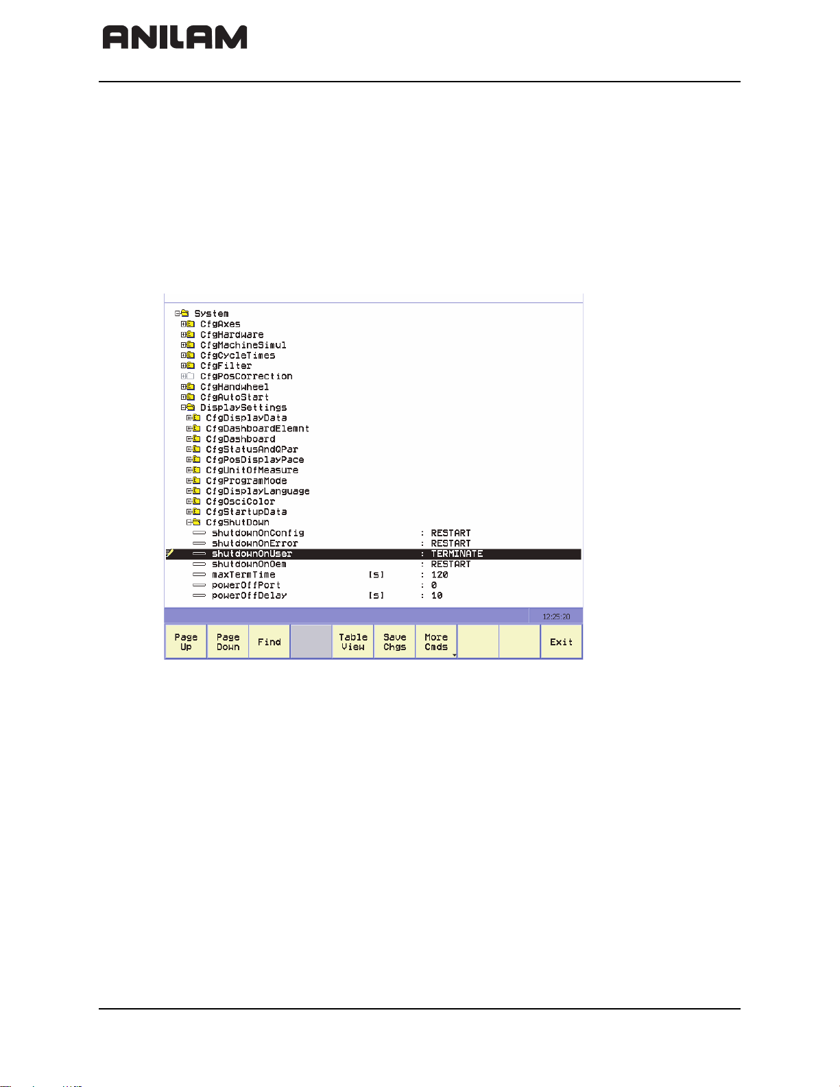
Software Update Procedure
To do a software update; you will place the update file “setup.zip” file on a Universal Serial
Bus (USB) stick (the setup.zip file is approximately 120 MB and you will need a USB
memory stick with at least 500 MB of free disk space).
• With the control up and running and the Estop pressed in, plug the USB stick into the
control.
• Press Config (SHIFT + F3) and the control displays a prompt for a password. Press
ENTER.
• Navigate to System > DisplaySettings > CfgShutDown > shutdownOnUser > and
select “Terminate” from the drop down menu:
• Press Exit (F10) and then F1 to save changes.
• Press ShutDown (SHIFT + F10) and press ShutDown (F1) to exit the software.
• Once you are out of the 6000i software and at a black screen, type MENU and press
ENTER.
• The 6000i menu displays on the screen. From the menu arrow down to the 8th item
(Update) and press
ENTER.
• Another menu is displayed, select the first item (Source: USB stick) and press ENTER.
• The control will look for the setup.zip file on the USB stick and prompt to press “1” to
begin the Update.
• Press “1” and press ENTER to start the update.
• The update may take 20 minutes to load. The screen may go into screen saver mode.
If the screen blanks out, press any key to watch the update progress.
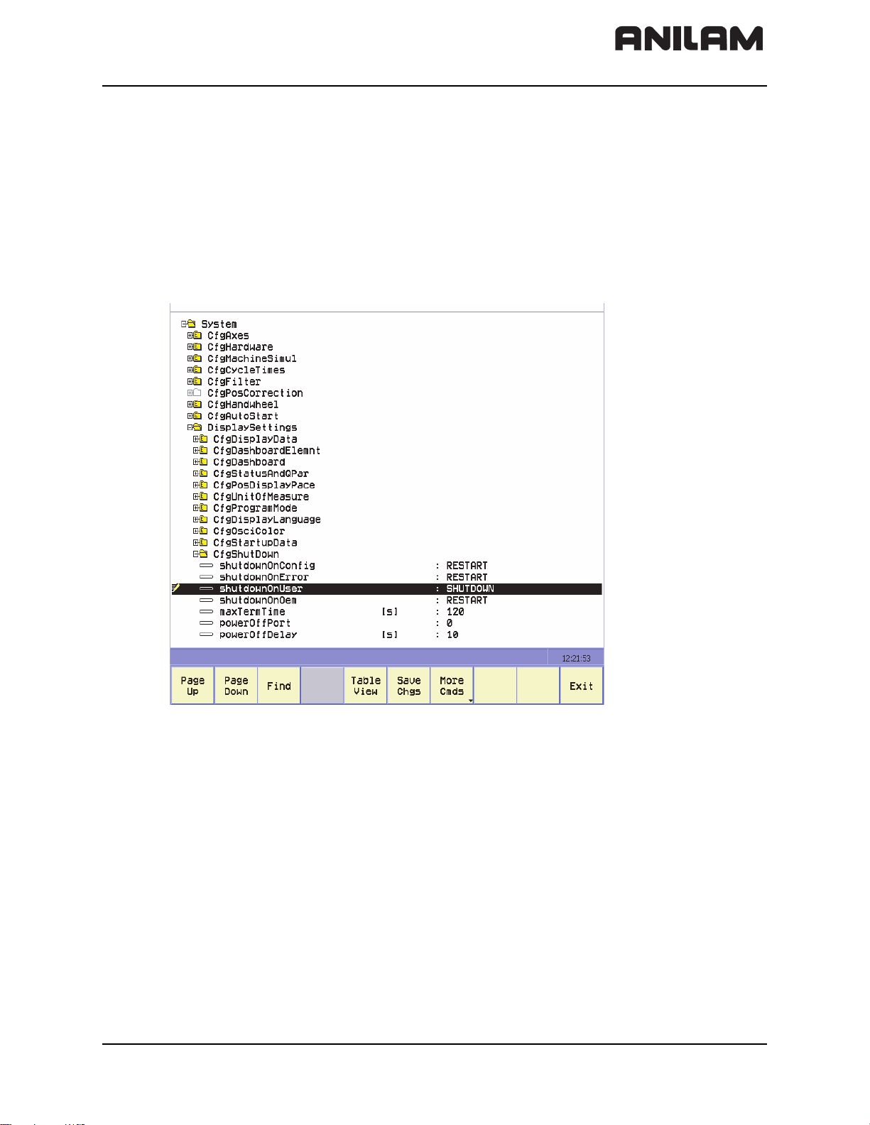
• When the update is complete, you are prompted to remove the USB stick and press
ENTER to reboot the control.
• Once the control reboots and comes up, home the machine, then reset the machine
parameter shutdownOnUser to SHUTDOWN.
1-4 All rights reserved. Subject to change without notice.
September 2008
Page 19
CNC Technical Manual
RESET MPARAMETER
P/N 627787-21 - Introduction
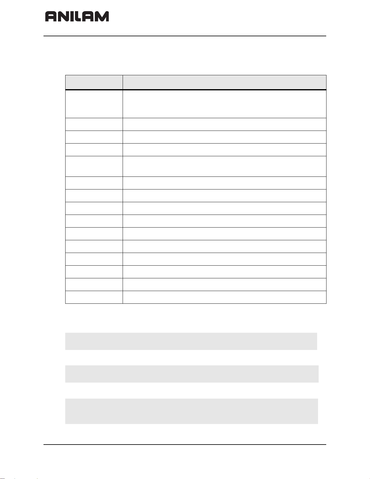
• If they are not already set, set shutdownOnConfig, shutdownOnError,
shutdownOnOem, maxTermTime, powerOffPort, and powerOffDelay to the values
below.
shutdownOnConfig RESTART
shutdownOnError RESTART
shurdownOnUser SHUTDOWN
shutdownOnOem RESTART
maxTermTime 120
powerOffPort 0
powerOffDelay 10
• Press Exit (F10) and then F1 to save changes; you are ready to run.
All rights reserved. Subject to change without notice. 1-5
September 2008
Page 20

CNC Technical Manual
P/N 627787-21 - Introduction
1-6 All rights reserved. Subject to change without notice.
September 2008
Page 21

CNC Technical Manual
P/N 627787-21 - Mounting and Electrical Installation
Section 2 - Mounting and Electrical Installation
The following topics are described in this section:
• General Information
• Handling the HDR Hard Disk and SIK
• Environmental Conditions
• Mounting Considerations
• Connection Overview
• MC 400 and CC 600 Pinouts
• I/O Module and I/O Expansion Base Module P/N Summary
• Handwheel Input
• Console FP 6000i
• Manual Panel MP 6000M and MP 6001M
General Information
Warning: Keep the following in mind during mounting and electrical installation:
• National regulations for power installations
• Interference and noise immunity
• Conditions of operation
• Mounting attitude
The following topics are described:
• Safety Precautions
• Degrees of Protection
• Electromagnetic Compatibility
Safety Precautions
Danger: Ensure that the main switch of the control or machine is switched off
Danger: Ensure that the equipment grounding conductor is continuous.
Danger: Incorrect or not optimized input values may lead to malfunction of the
when you engage or disengage connecting elements or connection
clamps.
Interruptions in the equipment grounding conductor may cause
damage to persons or property.
machine and may thus cause damage to persons or property.
Modifications of the machine configuration should be done with
caution and uncontrolled axis motions should be taken into account.
All rights reserved. Subject to change without notice. 2-1
September 2008
Page 22

CNC Technical Manual
Warning: In order to be able to judge the behavior of an NC controlled machine,
you need to have fundamental knowledge about drives, inverters,
controls and encoders. Inappropriate use may cause considerable
damage to persons or property.
ANILAM does not accept any responsibility for direct or indirect damage
caused to persons or property through incorrect use or operation of the
machine.
Danger: The interfaces for the PLC inputs/outputs, machine operating panel,
and PL connection comply with the requirements for basic insulation in
accordance with IEC 742 EN 50 178.
Only units that comply with the requirements of IEC 742 EN 50 178 for
basic insulation may be connected; otherwise, damage to persons or
property may be caused. The maximum DC voltage mean value of the
PLC inputs is 31 V.
Degrees of Protection
The following components fulfill the requirements for IP54 (dust and splash-proof
protection).
P/N 627787-21 - Mounting and Electrical Installation
• MC 400 (when properly installed)
• Machine operating panel (when properly installed)
• Handwheel
Electromagnetic Compatibility
This unit fulfills the requirements for Class A according to EN 55022 and is intended for
operation in industrially zoned areas.
Protect your equipment from interference by observing the following rules and
recommendations.
The following topics are described:
• Likely Sources of Interference
• Protective Measures
Likely Sources of Interference
Interference is mainly produced by capacitive and inductive coupling from electrical
conductors or from device inputs/outputs, such as:
• Strong magnetic fields from transformers or electric motors
• Relays, contactors, and solenoid valves
• High-frequency equipment, pulse equipment, and stray magnetic fields from switch-
mode power supplies
• Power lines and leads to the above equipment
2-2 All rights reserved. Subject to change without notice.
September 2008
Page 23
CNC Technical Manual
1. Sicherung anheben.
Lift the catch.
2. Lasche nach hinten drücken.
Press tab down.
Festplatte entriegeln . Unlocking the hard disk
Festplatte verriegeln . Locking the hard disk
1. hineindrüc
ken, nac
h vorne schieben. (Click)
Press hard disk down, slide it forwards. (click)
Grifflaschen benützen.
Use holding tabs.
2. nach hinten schieben. (Click)
Slide it bac
kwards. (click)
1.
2.
P/N 627787-21 - Mounting and Electrical Installation
Protective Measures
• Keep a minimum distance of 20 cm from the control and its leads to interfering
equipment.
• A minimum distance of 10 cm from the control and its leads to cables that carry
interference signals. For cables in metallic ducting, adequate decoupling can be
achieved by using a grounded separation shield.
• Shielding according to EN 50 178
• Use potential compensating lines with 6 mm
2
cross-sections
• Use only genuine ANILAM cables, connectors, and couplings
Handling the HDR Hard Disk and the SIK
The following topics are described:
• Shipping Brace of the HDR
• Installing/Removing the HDR and SIK
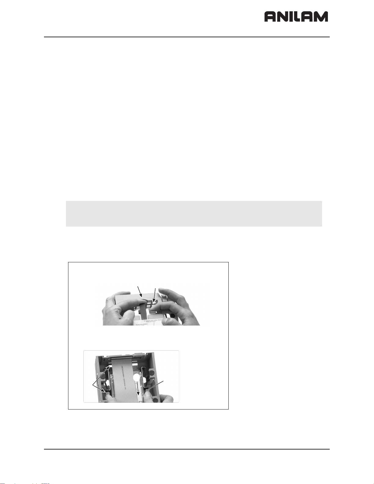
Shipping Brace of the HDR
The HDR hard disks of the MC 400 are fitted with a shipping brace. Before putting the
6000i into service, the shipping brace of the hard disk must be removed.
Warning: Do not transport the HDR with the MC 400 after you have installed the
HDR. The shipping brace for the hard disk is not required when the
machine is being transported.
Should servicing become necessary (i.e. the HDR is being shipped on its own), the hard
disk must be secured with the shipping brace. Refer to Figure 2-1.
Figure 2-1, Unlocking/Locking the Hard Drive
All rights reserved. Subject to change without notice. 2-3
September 2008
Page 24
CNC Technical Manual
P/N 627787-21 - Mounting and Electrical Installation
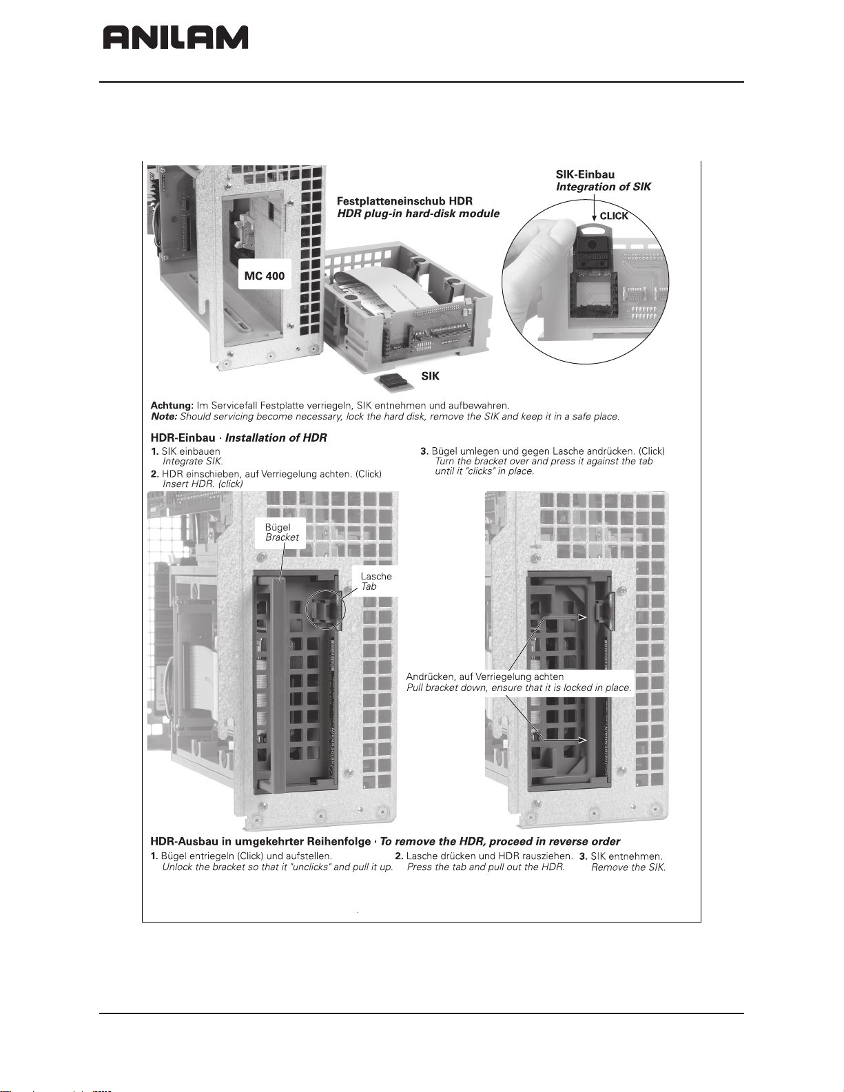
Installing/Removing the HDR and SIK
Refer to Figure 2-2.
Figure 2-2, Unlocking/Locking the Hard Drive
2-4 All rights reserved. Subject to change without notice.
September 2008
Page 25

CNC Technical Manual
P/N 627787-21 - Mounting and Electrical Installation
Environmental Conditions
The following topics are described:
• Heating and Cooling
• Humidity
• Mechanical Vibration
Heating and Cooling
Danger: The permissible ambient temperature in operation is between 0 °C
and 40 °C (32 °F to 104 °F). Any deviation from this will impair the
operating safety of the machine.
Ensure adequate cooling as follows:
• Provide sufficient space for air circulation.
• Install in a fan to extract warm air. Do not allow pre-warmed air to be blown into the
unit. The warmed air should flow over surfaces such as sheet metal, which enable heat
dissipation.
• Where the chassis is a closed steel housing without assisted cooling, the formula for
heat conduction is 3 W/m2 of surface per °C air temperature difference between inside
and outside.
• Use a heat exchanger with separate internal and external circulation.
• Do not blow external air through the control cabinet to exchange the internal air. Fine
dust or vapors could damage electronic assemblies. If no other method of cooling is
possible, ensure that the fan draws warm air out of the electrical cabinet and pulls in air
that is adequately filtered. Service the filter regularly.
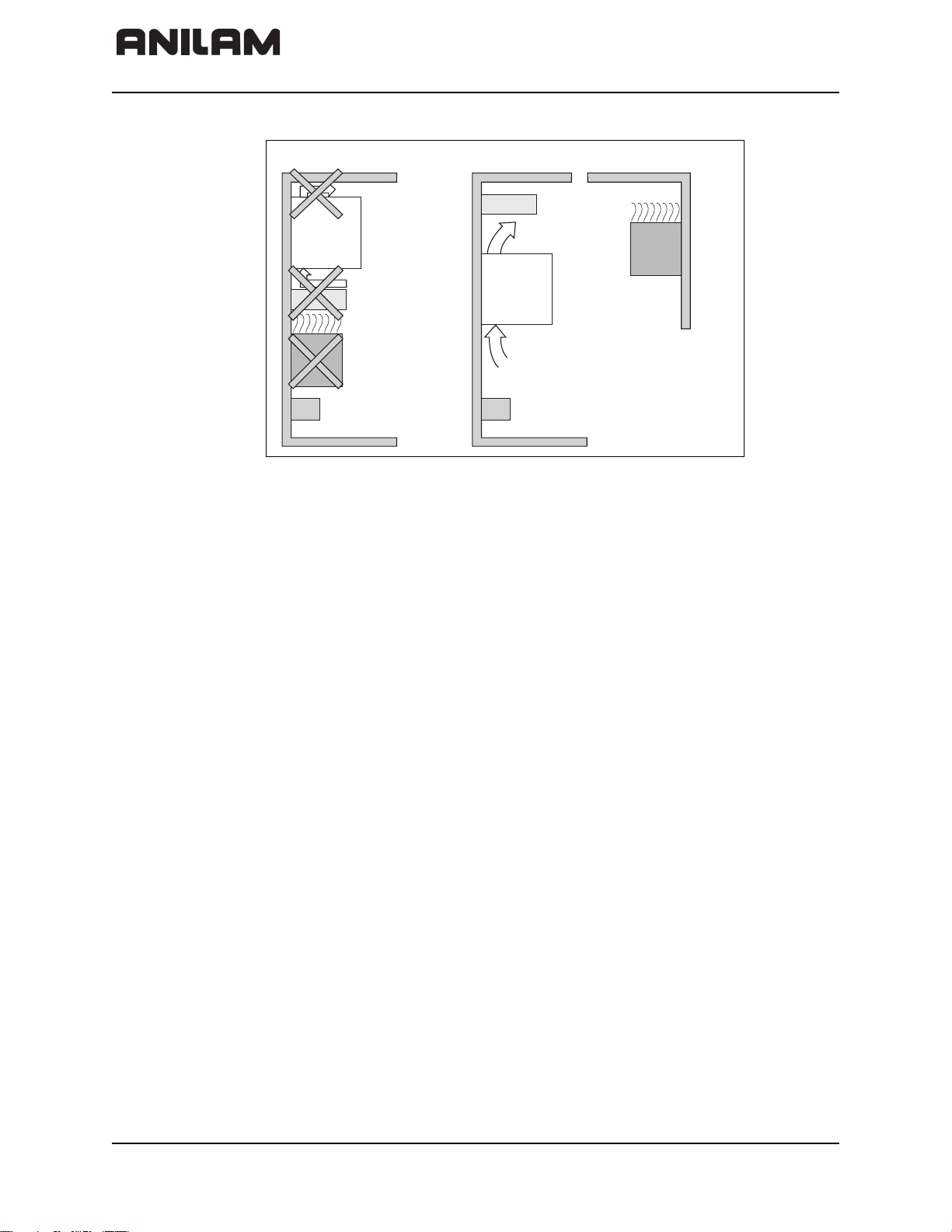
A heat exchanger or a cooling unit is preferable for controlling the internal temperature of
the electrical cabinet. Refer to Figure 2-3, Correct Positioning.
If filtered air is blown into the electrical cabinet for cooling purposes, the standard EN 50
178 applies, which permits contamination level 2.
Danger: Be sure to take the measures required for preventing dust from
entering the electrical cabinet.
Dust depositing inside electrical devices may cause them to fail and
impair the safety of the system.
All rights reserved. Subject to change without notice. 2-5
September 2008
Page 26
CNC Technical Manual
CorrectIncorrect
Blocking
elements
Elements with
considerable heat
generation
P/N 627787-21 - Mounting and Electrical Installation
Figure 2-3, Correct Positioning
Humidity
Permissible humidity:
• Maximum 75% in continuous operation
• Maximum 95% for not more than 30 days a year (randomly distributed)
In tropical areas it is recommended that the control not be switched off, so that
condensation is avoided on the circuit boards.
Mechanical Vibration
Permissible vibration:
Permissible shock:
± 0.075 mm, 10 to 41 Hz
2
5 m/s
100 m/s
300 m/s
, 41 Hz to 500 Hz
2
, 11 ms during operation
2
, 11 ms during transport (with ship-
ping brace for hard disk)
2-6 All rights reserved. Subject to change without notice.
September 2008
Page 27
CNC Technical Manual
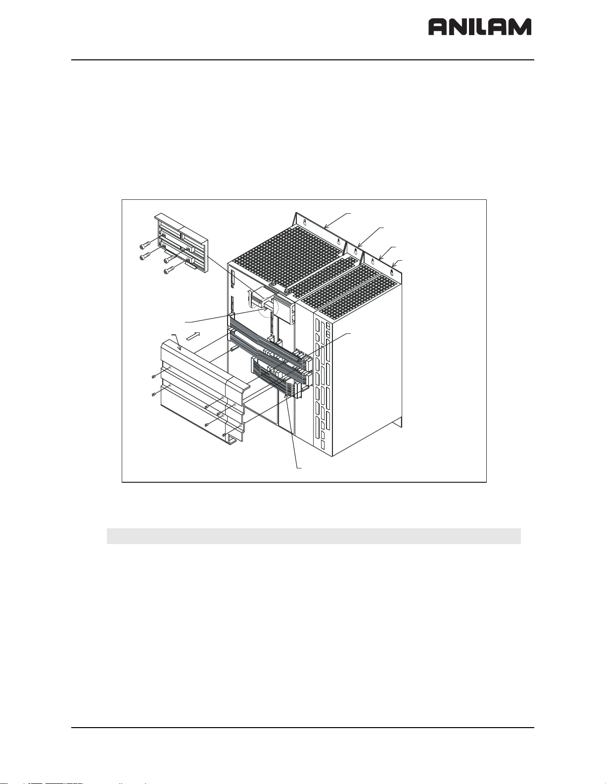
Conductor bar
Covers
Power su pply
PWM
Current Cont roller (CC)
Amplifier Power Module
(APM)
Amplifier-SA
POSITION ING
Main Computing (MC)
unit
P/N 627787-21 - Mounting and Electrical Installation
Mounting Considerations
The following topics are described:
• MC, CC, Inverter, and Amplifier Power Module
• Shipping Brace of the Hard Drive
• Installing and Removing the Hard Drive and SIK
• Display
MC, CC, Inverter, and Amplifier Power Module
Refer to Figure 2-4.
Figure 2-4, Positioning the MC, CC, Inverter, and Power Module
Note: Refer to “Section 9 - Drawings” for dimensions and clearances.
All rights reserved. Subject to change without notice. 2-7
September 2008
Page 28

CNC Technical Manual
P/N 627787-21 - Mounting and Electrical Installation
Shipping Brace of the Hard Drive
The 6000i hard drive is fitted with a shipping brace. Before putting the 6000i into service,
the shipping brace must be removed.
Warning: Do not transport the Hard Drive with the 6000i after you have installed
the Hard Drive. The shipping brace for the Hard Drive is not required
when the 6000i is being transported.
Should servicing become necessary (that is, the Hard Drive being shipped on its own),
the hard disk must be secured with the shipping brace.
To unlock the Hard Drive:
1. Lift the catch
2. Press down tab
To lock the Hard Drive:
1. Press the hard disk down, slide it forwards (click)
2. Using the holding tabs, slide it backwards (click)
Installing and Removing the Hard Drive and SIK
Should servicing the Hard Drive become necessary, lock the Hard Drive, remove the
System ID Key (SIK) and keep it in a safe place.
To Install the Hard Drive:
1. Integrate the SIK
2. Insert the Hard Drive
3. Turn the bracket over and press it against the tab until it “clicks” in place
To remove the Hard Drive:
1. Unlock the bracket so that it “unclicks” and pull it up
2. Press the tab and pull out the Hard Drive
3. Remove the SIK
Display
For space requirements, refer to Figure 9-1, Console.
Note: The display is sensitive to electromagnetic or magnetic noise. Strong fields
can lead to slight distortions of the picture. Ensure a minimum clearance of
0.5 m (1.64 ft).
2-8 All rights reserved. Subject to change without notice.
September 2008
Page 29
CNC Technical Manual
P/N 627787-21 - Mounting and Electrical Installation
Connection Overview
The following topics are described:
• Connecting MC 400 and CC 600 with Maximum Six Control Loops
• Cable and Basic Circuit Overview
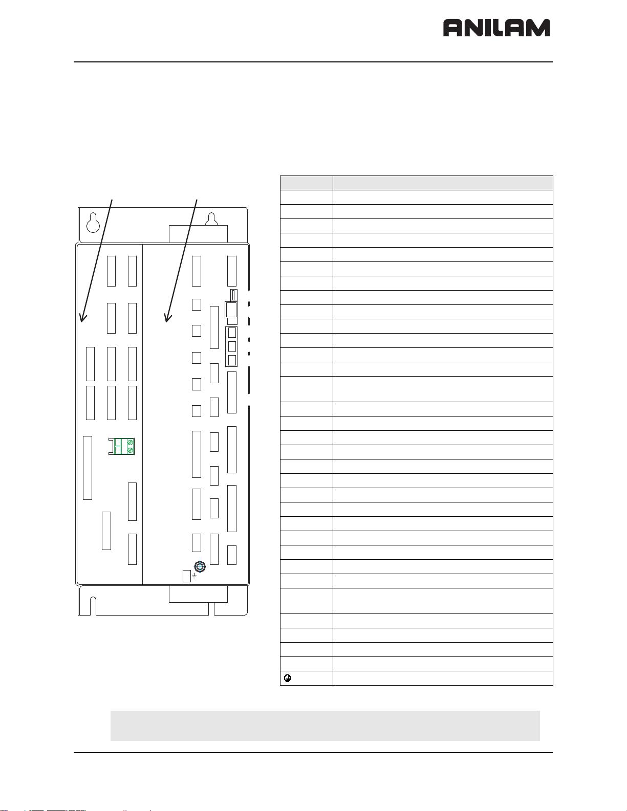
Connecting MC 400 and CC 600 with Maximum Six Control Loops
Refer to Figure 2-5
Conctr. Description
CC 600 MC 400
X1–X5 Axes position encoder 1 Vpp
X15–X20 Axis speed encoder 1 Vpp
X51–X56 PWM output
X15 X17
X16
X18
X52
X51
X54 X 56
X69
X166
X53
X55
5V
0V
X19
X20
X12
X13
X23
X27
X28
X10
X45
X48
X8
B
X49
X1
X2
X3
X4
X5
X165
X46
X42
X147
X141
X26
X30
X34
X44
X41
X8 Nominal value output, analog
X12 Touch probe for workpiece measurement
X13 Touch probe for tool measurement
X23 Handwheel input
X26 Ethernet data interface
X27 COM1 data interface (RS-232)
X28 COM2 data interface (RS-422)
X141,
X142
X30 Do not use
X34 24 V for control-is-ready output (X41/34)
X41 PLC output
X42 PLC input
X44 24 V PLC power supply
X45 Keyboard
X46 Manual panel
X147 PLC Expansion
X48 PLC analog input
X49 Flat panel display
X69 Power supply
X10 Reserved
X165,
X166
USB interface
Reserved
X150 is at bottom of CC 600 housing
CONNECTIONS
X150 Axis-specific drive release
X142 is at bottom of MC 400 housing
B Signal ground
Equipment ground (YL/GN)
Figure 2-5, MC 400 and CC 600 Connections
Warning: Do not engage or disengage any connecting elements while the unit is
under power.
All rights reserved. Subject to change without notice. 2-9
September 2008
Page 30

CNC Technical Manual
Cable and Basic Circuit Overview
For a cable overview, refer to Figure 9-22, Cable Overview for systems with Spindle Axis
(SA xxxx) amplifiers and Figure 9-23, Cable Overview, Modular for systems with
modular spindle and axis amplifiers.
For basic circuit diagrams, refer to Figure 9-24, Basic System Diagram and
Figure 9-19, Basic Servo Turn On Circuit.
MC 400 and CC 600 Pinouts
Refer to Figure 2-5, MC 400 and CC 600 Connections, Figure 9-5, CC 600 & MC 400,
and Figure 9-6, CC 600 & MC 400 Dimensions.
The following topics are described:
P/N 627787-21 - Mounting and Electrical Installation
• Position Control for Encoders
• Encoders for Speed Control
• Touch Probe
• PWM Connection to Axis/Spindle Motors
• CNC Power Supply and Control Signals
• Control-Is-Ready Signal
• Power Supply for PLC Outputs
• Buffer Battery
• Analog Nominal Value Output
• Analog Input
• Switching Inputs 24 VDC (PLC)
• Switching Outputs 24 VDC (PLC)
• Flat Panel Display
• Manual Panel
• CNC Keyboard
• I/O Module Connection
• Data Interfaces
• USB Interface
• Drive Controller Enable
• PLC Input/Output Units
2-10 All rights reserved. Subject to change without notice.
September 2008
Page 31

CNC Technical Manual
P/N 627787-21 - Mounting and Electrical Installation
Position Control for Encoders
X1–X4 are linear encoder axis position connections. X5 is the spindle encoder position
connection. ANILAM CNCs are designed to be used with linear encoders or rotary
encoders for position control. Refer to Table 2-1 for linear encoder pinouts.
ANILAM recommends using linear encoders with distance-coded reference marks or with
EnDat interface. These encoders reduce significantly the travel distance required to
establish absolute position.
Maximum input frequency: 350 kHz.
Table 2-1, X1–X-5: Encoder Position Control Connections (1 V
PP amplitude
)
Chassis Encoder Cable
D-Sub Connection
(Male) 15-Pin
1+5 V (U
20 V (U
Assignment
) 1 Brown/Green
P
) 2 White/Green
N
D-Sub Connector
(Female) 15-Pin
Color
3A+ 3 Brown
4 A– 4 Green
50 V5
6B+6 Gray
7B–7 Pink
80 V8
9 +5 V 9 Blue
10 R+ 10 Red
11 0 V 11 White
12 R– 12 Black
13 0 V 13
14 Do not assign 14 Violet
15 Do not assign 15
Housing External shield Housing External shield
The encoder signals are interpolated 1024-fold.
All rights reserved. Subject to change without notice. 2-11
September 2008
Page 32

CNC Technical Manual
P/N 627787-21 - Mounting and Electrical Installation
Encoders for Speed Control
Maximum input frequency: 350 kHz. The speed encoder can also be used for position
control. X15–X18 and X20 are rotary encoder axis speed control connections. X19 is the
spindle encoder speed control connection.
X15–X20 Rotary Encoder (1 V
PP amplitude
)
Refer to Table 2-2.
Table 2-2, X15–X20: Encoder Speed Control Connections - Pinout
MC 400 Adapter Cable
D-Sub
Connctn.
(Male)
25-Pin
1+ 5 V (U
20 V (U
3 A+ 3 Green/Black 1
4 A– 4 Yellow/Black 2
50 V 5
6B+ 6 Blue/Black11
7 B– 7 Red/Black 12
8 0 V 8 Internal shield 17
9 Not assigned 9
10 0 V 10
11 Not assigned 11
12 Not assigned 12
13 Temperature + 13 Yellow 8
14 +5 V or not assigned 14 Blue 16
15 Analog output (test) 15
16 0 V 16 White 15
17 R+ 17 Red 3
18 R– 18 Black 13
19 C+ 19 Green 5
20 C– 20 Brown 6
21 D+ 21 Gray 14
22 D– 22 Pink 4
23 +5 V (test) 23
24 0 V 24
25 Temperature– 25 Violet 9
Housing External shield Housing External shield Housing
Assignment
) 1 Brown/Green 10
P
) 2 White/Green 7
N
D-Sub
Connctr.
(Female)
25-Pin
Color(s)
Connctr.
(Female)
17-Pin
Note: The 1 Vpp signals are interpolated by a factor of 1024.
The rotary encoder to motor cable is ANILAM P/N 342000XX, where
XX = 10, 15, 20, 25, 30, 35, 40, and 45 feet.
2-12 All rights reserved. Subject to change without notice.
September 2008
Page 33

CNC Technical Manual
P/N 627787-21 - Mounting and Electrical Installation
Touch Probe
Use the touch probe for workpiece or tool measurement during machining. Refer to
Table 2-3 and Table 2-4.
Table 2-3, X12: Touch Probe Input for Workpiece Measurement
D-Sub Terminal
(Female) 15-pin
Assignment
10 V
2 Do not use
3 Ready
4Start
5 + 15 V ± 10 % (maximum 1000mA)
6 + 5 V ± 5 % (maximum 100mA)
7 Battery warning (jump to pin 5 for
wired probe)
80 V (U
)
N
9 Trigger signal
10
Trigger signal
1
11 to 15 Do not use
Housing External shield
1
Stylus at rest means logic level High
Table 2-4, X13: Touch Probe Input for Tool Measurement
D-Sub Terminal
(Female) 9-pin
Assignment
1 Ready
20 V (U
)
N
3 Do not use
4 + 15 V ± 5 % (U
)
P
5 Do not use
6 Do not use
7 + 5 V ± 5 % (U
)
P
8 Trigger signal
9
Trigger signal
1
Housing External shield
1
Stylus at rest means logic level High
The 6000i CNC offers two inputs for touch probes:
• X12 connector – probe input for workpiece measurement (3-D probe)
• X13 connector – probe input for tool measurement
All rights reserved. Subject to change without notice. 2-13
September 2008
Page 34

CNC Technical Manual
5
8
5
10
1
6000i Connector X-12
Red
Green
Blue
Yello w
3
7
Battery Signal
.
.
4
9
2
Housing
6000i Connector X-13
A5
B7
B6
A6
1
.
P/N 627787-21 - Mounting and Electrical Installation
Corded **Renishaw® probes have to be interfaced to the control signal levels in either
connector X12 and/or X13. The following figures represent the connection of the MP11
3-D corded touch probe (Figure 2-6), the TS27R tool probe (Figure 2-7), the **BLUM®
laser probe (Figure 2-8), and the OMP-40 cordless touch probe (Figure 2-9) to the 6000i
system:
Figure 2-6, Renishaw® MP11 3-D Corded Touch Probe
Renishaw® MP11 curly cable: Blue 8, Green 5, Yellow 10, Red Jump pin 7 to pin 5
Note: An input should be connected through a draw-down resister in such a way
that it is pulled low when the probe is connectred so the PLC can disable the
spindle and tool changes.
Figure 2-7, TS27R Tool Probe
Renishaw® MI-8 interface for B6 TS27-R tool probe: A5 4,B7 9, A6 2
Switch SW1 in MI-8 interface must be in N/C position
-----** Renishaw® is a registered trademark of Renishaw plc.
** BLUM® is a registered trademark of BLUM-Novotest GmbH.
2-14 All rights reserved. Subject to change without notice.
September 2008
Page 35

CNC Technical Manual
P/N 627787-21 - Mounting and Electrical Installation
AIR SUPPL Y UNIT
FOR LASER SYSTEM
PROBE SIGNALS
TO iPLC
X34 - 2
X34 - 1
O_ ON_LAS _PROB_ ENABLE _0
O_ ENA_1_LAS _PROB _EN ABLE_ 1
O_ENA _2_LAS _PROB _ENABLE _2
I_LASER _ STAT
I_LASER _ OK
I_LASER _ DYN
SHIELD
PROBE SIGNALS
1
2
+24 V ( B R N )
3
4
5
6
7
8
9
LASER NANO
(BLUM P87.0634)
24V COM (WHT)
ENABLE 0 (YEL )
ENABLE 1 (PNK )
ENABLE 2 (VIO )
STATIC (GRY)
LASER OK (BLU )
DYNAMIC (GRN)
TO PLC
INPUTS
(BLUM 51.010-3)
AIR SOLEN OID 1
AIR SOLEN OID 2
24V COM (WHT)
SW_SIGNAL (BRN)
24V COM
24V COM
INT ERFACE CABLE
(BLUM 12.345- 3)
AIR LINES
TO PROBE
AIR BARRIER
PISTON SHU TT ER
TO X13
X12
X13
X49
X141
X26
X23
X30
X34
X27
X44
X1
X41
X28
X2
Figure 2-8, BLUM® Laser Touch Probe
The Blum Laser Tool Probe requires three outputs and three inputs to be setup in the PLC
as shown above. It is also necessary to create four M-codes from M550 to M555. The Mcode numbers cannot be changed as they are hard coded into the tool probing canned
cycles.
M550: Laser Probe On
M551 Laser Probe Off
M552 Enable 1 On
M553 Enable 1 Off
M554 Enable 2 On
M555 Enable 2 Off
Optional Blum Laser M-codes:
M556 Blow Nozzle On
M557 Blow Nozzle Off
The following topics are described:
• PLC Additions for Blum Laser Probing
• Tool Probe Parameter Setup
• Spindle Probe Setup
All rights reserved. Subject to change without notice. 2-15
September 2008
Page 36

CNC Technical Manual
PLC Additions for Blum Laser Probing
The following topics are described:
P/N 627787-21 - Mounting and Electrical Installation
• PLC Input Labels and Connections to Blum Probe
• PLC Output Labels and Connections to Blum Probe
PLC Input Labels and Connections to Blum Probe
I_Laser_OK -> Blum “Laser OK” (Blue wire)
I_Laser_Dyn -> Blum “Dynamic” (Green wire)
I_Laser_Stat -> Blum “Static” (Gray wire)
PLC Output Labels and Connections to Blum Probe
O_On_Las_Prob_Enable_0 -> Blum “Enable 0” (Yellow wire) and also the coils of
the Air Barrier and Piston Shutter. (Ensure you
install a back surge diode between the solenoid coil
and 24V common to protect the output.)
O_Ena_Las_Prob_Enable_1 -> Blum “Enable 1” (Pink wire)
O_Ena_Las_Prob_Enable_2 -> Blum “Enable 2” (Violet wire)
O_Blow_Nozzle_Las_Prop_On -> Blum optional air blast
Plus 24 VDC connects to Blum +24V (Brown wire).
Common 24 VDC connects to Blum 24V COM (White wire) and also the common side of
the solenoid coils mentioned above.
The turning On and Off of the outputs are set up in the PLC module touchpro.scr with six
M-codes:
M550 Laser On
M551 Laser Off
M552 Enable 1 On
M553 Enable 1 Off
M554 Enable 2 On
M555 Enable 2 Off
And if the Blow Nozzle is on the probe, you would need to create two additional M-codes
for that, using:
M556 Blow Nozzle On
M557 Blow Nozzle Off
This way, the Blum cycles can turn on and off the outputs individually as needed for more
flexibility depending on the laser model.
An example for the M-code logic in touchpro.src is listed below and the associated entries
for M-code definition in the ANILAM 6000i control will also need to be made in the PLC
definition file GLB_PLCCFG.DEF and the machine configuration files of plc.cfg and
plc_oem.cfg.
2-16 All rights reserved. Subject to change without notice.
September 2008
Page 37

CNC Technical Manual
P/N 627787-21 - Mounting and Electrical Installation
Example of the PLC code in touchpro.src:
L NP_MG_M550_On_Laser_Probe_On
R O_Ena_2_Las_Prob_Enable_2
S O_Ena_1_Las_Prob_Enable_1
S O_On_Las_Prob_Enable_0
L NP_MG_M551_Off_Laser_Probe_Off
ON I_control_operational
R O_Ena_2_Las_Prob_Enable_2
R O_Ena_1_Las_Prob_Enable_1
R O_On_Las_Prob_Enable_0
L O_On_Las_Prob_Enable_0
A NP_MG_M550_On_Laser_Probe_On
S PN_MG_quit_M_function
LN O_On_Las_Prob_Enable_0
A NP_MG_M551_Off_Laser_Probe_Off
S PN_MG_quit_M_function
L NP_MG_M552_Enable_1_On
R O_Ena_2_Las_Prob_Enable_2
S O_Ena_1_Las_Prob_Enable_1
L O_Ena_1_Las_Prob_Enable_1
AN O_Ena_2_Las_Prob_Enable_2
A NP_MG_M552_Enable_1_On
S PN_MG_quit_M_function
L NP_MG_M554_Enable_2_On
R O_Ena_1_Las_Prob_Enable_1
S O_Ena_2_Las_Prob_Enable_2
L O_Ena_2_Las_Prob_Enable_2
AN O_Ena_1_Las_Prob_Enable_1
A NP_MG_M554_Enable_2_On
S PN_MG_quit_M_function
All rights reserved. Subject to change without notice. 2-17
September 2008
Page 38

CNC Technical Manual
P/N 627787-21 - Mounting and Electrical Installation
.
Reni shaw 's M I-12
Interface for
OM P-40 or MP -12
cordless probe
24 VDC
11
Error SSR
21
Machine Start 4
Probe Status SSR 1024
12 L ow Battery SSR
10
23
13
22
1716
2.2 K
Bat te ry Warn in g
6000M Connector X-12
Ready
3
Sta rt
Trigger Signal
In t er n al s hie ld
+1 5 V
7
5
0V
8
1
Figure 2-9, OMP-40 Cordless Touch Probe
Probes come in various different transmission systems: corded or cordless (infrared,
radio, or inductive). When a corded 3-D touch probe is connected to the control, the
spindle and tool changer should be automatically disabled in the PLC by means of an
input signal which is hardwired to the probe connector. Also the low battery signal should
be jumped to 15VDC when using a corded 3-D touch probe. When a cordless 3-D touch
probe is connected to the control, low battery and not ready (e.g. transmission medium
obstructed or probe in “sleep mode”) conditions are continuously monitored. Cordless
probes usually go into a “sleeping mode” to conserve battery charge. These probes are
automatically awakened by the CNC when probing is activated (M9387 X1).
Refer to the probe manufacture’s documentation for further details. Refer to the 6000i
CNC User’s Manual, P/N 627785-2X, for probe usage guidelines.
Tool Probe Parameter Setup
The tool probing parameters (the table probe) can be found on the control by going into
the machine configuration as follows (refer to Figure 2-10):
1. From the Manual mode, press
2. When asked for a password, simply press the
SHIFT then F3 (Config).
ENTER key.
3. Go into System>Probing>CfgToolProbingParameters
4. Remember that all numeric values are in metric.
Figure 2-10, Config Data Parameter Screen Capture
2-18 All rights reserved. Subject to change without notice.
September 2008
Page 39

CNC Technical Manual
P/N 627787-21 - Mounting and Electrical Installation
• Set toolProbeType: Standard or Laser (Standard is the default).
• Set useAnilamLaserCycles to YES to utilize the ANILAM laser table probe cycles.
These cycles have limited compatibility for the Blum laser probe, therefore if another
laser table probe is used, it may be necessary to set this to NO and use the cycles
provided by the particular probe manufacturer. This parameter is read by the PLC to
allow different input/output configuration.
• Set moveAxisParallelToLaserBeam (Laser probe only) to YES so the tool probing
cycles will locate both X and Y axes when calibrating a tool. Set to NO if the probe is
mounted in such a way that the axis parallel to the laser beam need not be moved.
• Set nominalProbeStylusDiameter, the overall nominal probe stylus diameter. For
example, 12mm for the Renishaw® probe, or for the Heidenhain probe use 40mm. On
a laser style probe this value would normally be zero. This is dependent on the probe
style and specifications (refer to your probe documentation).
• Set maxStrokeFromHome_FirstPick, represents the distance from machine Z home
with the shortest tool or the spindle face to just below the probe stylus top as the
maximum stroke for the initial probe pick.
• Set calibAndToolMeasurementRPM, the spindle RPM for tool touch. [For example,
set to 800 for standard probe type or 4000 for laser probe type tool presetter.]
• Set probeOrientation, the proper probe orientation. For example, if set to –1, the
probe should be installed on the right side of the table pointing toward the left in the –X
direction. See Table 2-5.
Table 2-5, Probe Orientation Settings
Probe Orientation
Settings
1 Probe is pointing to the right as you are facing the machine in +X
-1 Probe is pointing to the left of the machine in the -X direction.
2
-2 Probe is pointing toward you, toward the front of the machine in the
direction
Probe is pointing away from you, toward the back of the machine in
the +Y direction
-Y direction
Direction
• Set ZFirstPickFeedRate_Fast, the Z fast feedrate. [For example, set to 2000 mm per
minute (mm/min).]
Warning: When using G151, the tool travels down beyond the top of the probe
after the probe is tripped. For this reason, make sure that the fast
feedrate is not so high as to cause the tool to travel past the probe travel
causing damage to the probe. The maximum feedrate that can be used
is specific to the machine and may need to be set much lower to prevent
damage to the probe.
All rights reserved. Subject to change without notice. 2-19
September 2008
Page 40

CNC Technical Manual
Note: There is a maximum feedrate setting which is set by your machine tool
manufacturer in System > CfgHardware > maxTouchFeed. This will limit the
maximum feedrate allowed in these feedrate parameters.
P/N 627787-21 - Mounting and Electrical Installation
• Set the ZFirstPickFeedRate_Medium, the Z medium feedrate. [For example, set to
125 mm/min.]
• Set ZFirstPickFeedRate_Slow, the Z slow feedrate for the actual probe pick. [For
example, set to 10.0 mm/min.]
• Set ZRetractAmount. Amount to retract from top of probe after pick. [For example, set
to 4.0 mm.]
• Set XYRetractAmount. Amount to retract from side of probe after pick. [For example,
set to 4.0 mm.]
• Set ZRapidToStartPositionFromHome. Install the longest tool in the spindle and
bring the Z-axis to machine home. With a tape measure, measure the distance from the
tool tip to within 13 mm above the top of the probe stylus and enter that number into
ZRapidToStartPositionFromHome. When using G151, this causes the tool to rapid to
this position in the Z-axis before starting the initial probe touch in the Z-axis. This saves
time especially if the Z-feed must be set relatively slow to prevent probe over travel
after the probe has been tripped.
• Set diameterOfToolProbeGauge. The default gauge diameter of the tool calibration
standard. diameterOfToolProbeGauge can be overwritten by the D word in the G150
cycle. diameterOfToolProbeGauge is used in the G150 calibration only. [For example,
set to 12 mm.]
Spindle Probe Setup
The probing parameters can be found on the control by going into the machine
configuration as follows (refer to Figure 2-11):
1. From the Manual mode, press
2. When asked for a password, simply press the
3. Go into System>Probing>CfgSpindleProbingParameters
4. Remember that all numeric values are in metric.
Figure 2-11, Config Data Parameter Screen Capture (Additional Parameters
Displayed)
SHIFT then F3 (Config).
ENTER key.
• Set spindleProbeType, to Corded, Cordless, depending on the probe style.
2-20 All rights reserved. Subject to change without notice.
September 2008
Page 41

CNC Technical Manual
P/N 627787-21 - Mounting and Electrical Installation
• Set positioningFeedrate_Normally, the feedrate the control uses while positioning
the probe around the part. [For example, set to 1000 mm/min.]
• Set positioningFeedrate_FirstTouch, the feedrate the control uses while making its
initial touch finding the surface it is measuring. [For example, 125 mm/min.]
Note: There is a maximum feedrate setting which is set by your machine tool
manufacturer in System > CfgHardware > maxTouchFeed. This will limit the
maximum feedrate allowed in these feedrate parameters.
•Set nominalProbeStylusBallRadius, the diameter as measured with a micrometer.
[For example, set to 5 mm for a 10mm ball.]
• Set diameterOfSpindleProbeGauge, the exact diameter of the ring gauge used to
calibrate the spindle probe. [For example, 25.4 mm.]
• Set dwellTimeAfterProbeActive, the time recommended by the particular probe
manufacturer to wait after the probe is turned on before attempting a probe move.
• Set updateTloOrWorkOffsetZAxis, to WorkOffset or TLO. This only affects the G141
with a Q4 and Q5 which will store the result as the difference of the spindle probes TLO
and the top of the part in the Z axis work offset or will place the distance from machine
home to the surface being probed in the current active tool length offset.
Figure 2-12, Probe Tool Settings Found in System > Probing > CfgProbeTool > OEM
• orientSpeed, activateMStrobe, activateRetries, deactivateMStrobe,
deactivateTimeout, deactivateRetries, and autoDeactivateTime are not used and
should be set to zero (0) or 1 in the case of deactivateMStrobe.
• Set orientProperty to NONE for a wired spindle probe and MultiOrient for a wireless
probe.
• Set activationType to Pulse.
• Set activateTimeout to 4 seconds.
• Set deactivateType to Timeout.
All rights reserved. Subject to change without notice. 2-21
September 2008
Page 42

CNC Technical Manual
P/N 627787-21 - Mounting and Electrical Installation
PWM Connection to Axis/Spindle Motors
X51–X55 are the Pulse Width Modulation (PWM) axes connections. X56 is the spindle
encoder PWM axis connection.
X51–X56 PWM Connection
Refer to Table 2-6.
Table 2-6, X51–X56: PWM Connection to Motor
Ribbon Connector Assignment
1a PWM U1
1b 0V U1
2a PWM U
2b 0V U
3a PWM U
3b 0V U
2
2
3
3
4a –SH2
4b 0V (–SH2)
5a –SH1B
5b 0V (–SH1B)
6a +Iactl 1
6b –Iactl 1
7a 0 V (analog)
7b +Iactl
8a –Iactl
2
2
8b 0 V (analog)
9a Do not assign
9b Do not assign
10a Temperature warning
10b Ready
Logic level: 5 V
Analog signals I
: ±7.5 V
act
Maximum PWM frequency: 10 kHz
Note: The PWM frequency is defined via parameter. Defined via parameter
“ampPwmFreq” found in “CfgPowerStage” of the axis which corresponds to
the connectors X51–X56.
2-22 All rights reserved. Subject to change without notice.
September 2008
Page 43

CNC Technical Manual
P/N 627787-21 - Mounting and Electrical Installation
CNC Power Supply and Control Signals
X69: MC 400 Power Supply
Refer to Table 2-7 for the ribbon cable pinout.
Table 2-7, X69: Ribbon Cable Connector - Pinout
X69 Ribbon Cable
Connector 50-pin
Assignment
X69 Ribbon Cable
Connector 50-pin
Assignment
1a +5 V 14a –ERR.ZU.GR
1b +5 V 14b GND
2a +5 V 15a –ERR.I.GR
2b +5 V 15b GND
3a +5 V 16a –ERR.TMP
3b +5 V 16b GND
4a +5 V 17a RDY.PS
4b +5 V 17b GND
5a +5 V 18a –ERR.ILEAK
5b +5 V 18b GND
6a +12 V 19a Do not assign
6b +12 V 19b GND
7a +12 V 20a Do not assign
7b +12 V 20b GND
8a +5 V (separated) 21a Do not assign
8b 0 V (separated) 21b GND
9a +15 V 22a Do not assign
9b -15 V 22b GND
10a UZAN 23a Reserved (SDA)
10b 0 V 23b GND
11a IZAN 24a Reserved (–SCL)
11b 0 V 24b GND
12a –RES.PS 25a –RES.S
12b 0 V 25b GND
13a –PF.PS
13b GND
(Continued on adjacent table…)
All rights reserved. Subject to change without notice. 2-23
September 2008
Page 44

CNC Technical Manual
Control-Is-Ready Signal
X34: 24V Control-Is-Ready Signal
Refer to Table 2-8.
Table 2-8, X34: 24V Control-is-Ready Signal
Terminal Assignment
1 +24 V input
20V
Power Supply for PLC Outputs
The PLC of the MC 400 as well as the IEB 404 are powered by the 24 V control voltage of
the machine (in accordance with VDE 0551).
The control voltage must be smoothed with a minimum 1000 µF at a rated current
capacity of 150 µF/A. At a current load of 15 A, for example, this corresponds to a
capacity of 2250 µF.
EN 61 131-2:1994 permits:
P/N 627787-21 - Mounting and Electrical Installation
• 5% alternating voltage component is permissible
• Minimum absolute value: 20.4 VDC
• Maximum absolute value: 28.8 VDC
Warning: Use only original replacement fuses.
The following topics are described:
• Power Consumption
• Nominal Operating Current per Output
• X44: 24V Input for PLC Power Supply
• Power Supply for IEB 404
• IEB 404 Basic Module
• IEM 16-8D Input/Output Module
Power Consumption
If half of the outputs are switched at the same time, the following are the values for power
consumption:
MC 400: 115 W
IEB 404: Approx. 385 W
2-24 All rights reserved. Subject to change without notice.
September 2008
Page 45

CNC Technical Manual
≤≤≤
P/N 627787-21 - Mounting and Electrical Installation
Nominal Operating Current per Output
MC 400: 0.150 A
IEM 16-8D: 2 A
Simultaneity
2 outputs with 2 A each
4 outputs with 1 A each
8 outputs with 0.5 A each
Total current:
Out0 to Out7: 4 A
Out0 to Out3: 2 A
Out4 to Out7: 2 A
X44: 24V Input for PLC Power Supply
Refer to Table 2-9.
Table 2-9, X44 I/O Module Supply Voltage - Pinout
Connection
Terminal
Assignment PLC Outputs
1 +24 VDC cannot be switched off via
EMERGENCY STOP
2 +24 VDC can be switched off via
3 Y0:0 – Y0:15
EMERGENCY STOP
Y0:24 – Y0:30
control-is-ready signal
Y0:16 – Y0:28
40 V
Note: If the +24-V power supply (which cannot be shut off via emergency stop) is
missing at X44, the error message Supply voltage missing at X44 is
displayed.
Power Supply for IEB 404
Note: The MC 400 cyclically monitors the supply voltage of the IEB 404.
IEB 404 Basic Module
Refer to Table 2-10.
Table 2-10, X3 (Power Supply for Logic Circuit) - Pinout
Terminal Assignment
1 +24 VDC (20.4 V to 28.8 V)
2+0 V
IEM 16-8D Input/Output Module
Refer to Table 2-11.
Table 2-11, X6 (Power Supply for PLC Outputs) - Pinout
Terminal Assignment
9 +24 VDC (20.4 V to 28.8 V) for group 1
10 +24 VDC (20.4 V to 28.8 V) for group 2
All rights reserved. Subject to change without notice. 2-25
September 2008
Page 46

CNC Technical Manual
Buffer Battery
Buffer Battery
Note: Make a data backup before changing the buffer battery.
Danger: When exchanging the buffer battery, remember:
P/N 627787-21 - Mounting and Electrical Installation
• Switch off the machine and the 6000i.
• The buffer battery may be exchanged only by trained personnel.
Battery type: 1 lithium battery, type CR 2450N (Renata), Id. Nr. 315 878-01
If the voltage of the buffer battery falls below 2.6 V, the error message Exchange buffer
battery is displayed. If the voltage does not exceed 2.6 V, the error message is
reactivated after 30 minutes. Refer to Figure 2-13.
To exchange the battery:
• The buffer battery is located on the rear side of the MC 400.
• Exchange the battery; the new battery can be inserted in only one position.
Figure 2-13, Buffer Battery
2-26 All rights reserved. Subject to change without notice.
September 2008
Page 47

CNC Technical Manual
P/N 627787-21 - Mounting and Electrical Installation
Analog Nominal Value Output
Output ±10 V
Maximum load of analog outputs 2 mA
Maximum capacity 2 nF
Six analog outputs are available:
Connection X8: Analog output 1 to 6
The following topics are described:
• Nominal Value Output
• Analog Output 1 to 6
Nominal Value Output
The connecting cable to the nominal value outputs must not have more than one
intermediate terminal.
If you must branch to physically separate servo inputs, the connection must be made in a
grounded terminal box. The housing of the terminal box must be electrically connected
with the frame of the machine.
Analog Output 1 to 6
See Table 2-12.
Table 2-12, X8: Analog Output - Pinout
MC 400 Conn. Cable P/N 343007XX
D-Sub Connector
(Female) 15-Pin
Assignment
D-Sub Connector
(Female) 15-Pin
Color(s)
1 Analog output 1: ±10 V 1 Brown
2 Do not assign 2 Brown/Green
3 Analog output 2: ±10 V 3 Yellow
4 Analog output 5: ±10 V 4 Red/Blue
5 Analog output 3: ±10 V 5 Pink
6 Analog output 5: 0 V 6 Gray/Pink
7 Analog output 4: ±10 V 7 Red
8 Analog output 6: ±10 V 8 Violet
9 Analog output 1: 0 V 9 White
10 Do not assign 10 White/Gray
11 Analog output 2: 0 V 11 Green
12 Do not assign 12
13 Analog output 3: 0 V 13 Gray
14 Analog output 4: 0 V 14 Blue
15 Analog output 6: 0 V 15 Black
Shell External shield Shell External shield
All rights reserved. Subject to change without notice. 2-27
September 2008
Page 48

CNC Technical Manual
Analog Input
The MC 400 and the PLC Input/Output Board have analog inputs and inputs for Pt100
termistors.
The PLC Input/Output Board is available with and without analog inputs.
Voltage range: –10 V to +10 V
Input resistance: > 250 kW
Resolution: 10 mV (MC 400)
Internal value range: –100 to +100, at a resolution of 100 mV
The following topics are described:
P/N 627787-21 - Mounting and Electrical Installation
• Inputs for Pt 100 Thermistors
• Analog Voltage Cable Characteristics
• X48: PLC Analog Input
Inputs for Pt 100 Thermistors
Constant current: 5 mA
Temperature range: 0 °C (32 °F) to 100 °C (212 °F)
Resolution: 0.1 °C (32.18 °F)
Internal value range: 0 to 200, at a resolution of 0.5 °C (32.9 °F)
Analog Voltage Cable Characteristics
Characteristics of analog voltage connecting cable:
• Shielding
• 2 conductors with 0.14 mm
2
(AWG 7)
• Maximum length 50 meters (164 feet)
2-28 All rights reserved. Subject to change without notice.
September 2008
Page 49

CNC Technical Manual
P/N 627787-21 - Mounting and Electrical Installation
X48: PLC Analog Input
Warning: Remember to connect the analog inputs with the correct polarity.
Refer to Table 2-13.
Table 2-13, X48: PLC Analog Input - Pinout
S-Sub Connection (Female)
25-Pin
1I
2I
3U
4U
5I
6I
7U
8U
9I
10 I
11 U
12 U
+ Constant current for Pt 100
1
– Constant current for Pt 100
1
+ Constant current for Pt 100
1
– Constant current for Pt 100
1
+ Constant current for Pt 100
2
– Constant current for Pt 100
2
+ Constant current for Pt 100
2
– Constant current for Pt 100
2
+ Constant current for Pt 100
3
– Constant current for Pt 100
3
+ Constant current for Pt 100
3
– Constant current for Pt 100
3
Assignment
13 Do not assign
14 Analog input 1: –10 to +10 V
15 Analog input 1: 0 V (reference potential)
16 Analog input 2: –10 V to +10 V
17 Analog input 2: 0 V (reference potential)
18 Analog input 3: –10 V to +10 V
19 Analog input 3: 0 V (reference potential)
20 to 25 Do not assign
Housing External shield
Note: The interface complies with the requirements of EN 50 178 for “low
electrical separation.”
All rights reserved. Subject to change without notice. 2-29
September 2008
Page 50

CNC Technical Manual
Switching Inputs 24 VDC (PLC)
Input signals of the switching inputs on the MC 400 and the IEM 16-8D. Refer to
Table 2-14 and Table 2-15.
Table 2-14, I/O Module Voltage Requirements
Voltage Ranges: MC 400 IEM 16-8D I/O Module
“1” signal: Ui 13 V to 30.2 V 13 V to 28.8 V
“0” signal: Ui –20 V to 3.2 V –20 V to 2.5 V
Current Ranges:
“1” signal: Ui 3.8 mA to 8.9 mA 2.5 mA to 5.8 mA
“0” signal: Ii when Ui = 3.2 V 1.0 mA 0.3 mA
Table 2-15, Addresses of the Switching Inputs
Address Number Device
I:00 – I:31 31 + Control-Is-Ready Signal MC 400, X42 (PLC input)
I:128 – I:152 25 MC 400, X46 (machine operating panel)
I:64 to I:127 64 IEB 404 (IEM 16-8D)
I:192 to I:255 64 IEB 404 (IEM 16-8D)
I:256 to I:319 64 IEB 404 (IEM 16-8D)
I:320 to I:383 64 IEB 404 (IEM 16-8D)
P/N 627787-21 - Mounting and Electrical Installation
The following topics are described:
• X42: PLC Input on the CNC
• PLC Inputs on the IEB 404
2-30 All rights reserved. Subject to change without notice.
September 2008
Page 51

CNC Technical Manual
P/N 627787-21 - Mounting and Electrical Installation
X42: PLC Input on the CNC
The connecting cables are:
P/N 343007XX is available in lengths of 3 feet, 10, 15, 20, 30, 45, and 60 feet, and is an
open-ended wire-type cable. The last two digits of the P/N indicate the cable length. For
example, 34300703 indicates a 3-foot cable. Refer to Table 2-16.
Table 2-16, X42: PLC Input to the MC 400 - Pinout
MC 400 Conn. Cable P/N 343007XX
Female openended wires
Assignment
D-Sub Connctr.
37-Pin
Color(s)
1 I:00 **X HOME 1 Black
2 I:01 **Y HOME 2 Red
3 I:02 **Z HOME 3 White
4 I:03 **CNCACK 4 Green
5 I:04 **U HOME 5 Orange
6 I:05 **W HOME 6 Blue
7 I:06 7 Brown
8 I:07 8 Yellow
9 I:08 9 Violet
10 I:09 10 Gray
11 I:10 11 Pink
12 I:11 12 Tan
13 I:12 13 Red/Green
14 I:13 14 Red/Yellow
15 I:14 15 Red/Black
16 I:15 16 White/Black
17 I:16 17 White/Red
18 I:17 18 White/
Green
19 I:18 19 White/Yel-
low
20 I:19 20 White/Blue
21 I:20 21 White/
Brown
22 I:21 22 White/
Orange
23 I:22 23 White/Gray
24 I:23 24 White/Violet
** Hard Coded Function (Continued…)
All rights reserved. Subject to change without notice. 2-31
September 2008
Page 52

CNC Technical Manual
P/N 627787-21 - Mounting and Electrical Installation
Table 2-16, X42: PLC Input to the MC 400 - Pinout (Continued)
MC 400 Conn. Cable P/N 343007XX
Female openended wires
Assignment
D-Sub
Connctr.
37-Pin
Color(s)
25 I:24 25 White/Black/Red
26 I:25 26 White/Black/Green
27 I:26 27 White/Black/Yellow
28 I:27 28 White/Black/Blue
29 I:28 29 White/Black/Brown
30 I:29 30 White/Black/
Orange
31 I:30 **Software ESTOP 31 White/Black/Gray
32 I:31 **Software DRIVE ENABLE 32 White/Black/Violet
33 I:32 **DRIVE ENABLE 33 White/Black/Black
34 Do not assign 34 White/Red/
Black
35 Do not assign 35 White/Red/
Red
36 Do not assign 36 White/Red/
Green
37 Do not assign 37 White/Red/
Blue
Shell External shield Shell External shield
** Hard Coded Function
2-32 All rights reserved. Subject to change without notice.
September 2008
Page 53

CNC Technical Manual
P/N 627787-21 - Mounting and Electrical Installation
PLC Inputs on the IEB 404
X4 to X5: PLC Inputs
Refer to Table 2-17 and Table 2-18, X5: IEM 16-8D I/O Module - Pinout.
Note: he 0-V terminals of X4 and X5 of the IEM 16-8D are connected internally.
These connections are used for connecting the potential of the electronics
and for operating the LEDs. Since only a low current is required.
Table 2-17, X4: IEM 16-8D I/O Module - Pinout
X4
Assignment
Terminal
1 2 3 4 5 6 7 8 9 10
First IEB 404 Slot 1 0 V 0 V I:64 I:65 I:66 I:67 I:68 I:69 I:70 I:71
Slot 2 0 V 0 V I:80 I:81 I:82 I:83 I:84 I:85 I:86 I:87
Slot 3 0 V 0 V I:96 I:97 I:98 I:99 I:100 I:101 I:102 I:103
Slot 4 0 V 0 V I:112 I:113 I:114 I:115 I:116 I:117 I:118 I:119
Second IEB 404 Slot 1 0 V 0 V I:192 I:193 I:194 I:195 I:196 I:197 I:198 I:199
Slot 2 0 V 0 V I:208 I:209 I:210 I:211 I:212 I:213 I:214 I:215
Slot 3 0 V 0 V I:224 I:225 I:226 I:227 I:228 I:229 I:230 I:231
Slot 4 0 V 0 V I:240 I:241 I:242 I:243 I:244 I:245 I:246 I:247
Third IEB 404 Slot 1 0 V 0 V I:256 I:257 I:258 I:259 I:260 I:261 I:262 I:263
Slot 2 0 V 0 V I:272 I:273 I:274 I:275 I:276 I:277 I:278 I:279
Slot 3 0 V 0 V I:288 I:289 I:290 I:291 I:292 I:293 I:294 I:295
Slot 4 0 V 0 V I:304 I:305 I:306 I:307 I:308 I:309 I:310 I:311
Fourth IEB 404 Slot 1 0 V 0 V I:320 I:321 I:322 I:323 I:324 I:325 I:326 I:327
Slot 2 0 V 0 V I:336 I:337 I:338 I:339 I:340 I:341 I:342 I:343
Slot 3 0 V 0 V I:352 I:353 I:354 I:355 I:356 I:357 I:358 I:359
Slot 4 0 V 0 V I:368 I:369 I:370 I:371 I:372 I:373 I:374 I:375
All rights reserved. Subject to change without notice. 2-33
September 2008
Page 54

CNC Technical Manual
Table 2-18, X5: IEM 16-8D I/O Module - Pinout
X5
P/N 627787-21 - Mounting and Electrical Installation
Assignment
First IEB 404 Slot 1 0 V 0 V I:72 I:73 I:74 I:75 I:76 I:77 I:78 I:79
Slot 2 0 V 0 V I:88 I:89 I:90 I:91 I:92 I:93 I:94 I:95
Slot 3 0 V 0 V I:104 I:105 I:106 I:107 I:108 I:109 I:110 I:111
Slot 4 0 V 0 V I:120 I:121 I:122 I:123 I:124 I:125 I:126 I:127
Second IEB 404 Slot 1 0 V 0 V I:200 I:201 I:202 I:203 I:204 I:205 I:206 I:207
Slot 2 0 V 0 V I:216 I:217 I:218 I:219 I:220 I:221 I:222 I:223
Slot 3 0 V 0 V I:232 I:233 I:234 I:235 I:236 I:237 I:238 I:239
Slot 4 0 V 0 V I:248 I:249 I:250 I:251 I:252 I:253 I:254 I:255
Third IEB 404 Slot 1 0 V 0 V I:264 I:265 I:266 I:267 I:268 I:269 I:270 I:271
Slot 2 0 V 0 V I:280 I:281 I:282 I:283 I:284 I:285 I:286 I:287
Slot 3 0 V 0 V I:296 I:297 I:298 I:299 I:300 I:301 I:302 I:303
Slot 4 0 V 0 V I:312 I:313 I:314 I:315 I:316 I:317 I:318 I:319
Fourth IEB 404 Slot 1 0 V 0 V I:328 I:329 I:330 I:331 I:332 I:333 I:334 I:335
Slot 2 0 V 0 V I:344 I:345 I:346 I:347 I:348 I:349 I:350 I:351
Slot 3 0 V 0 V I:360 I:361 I:362 I:363 I:364 I:365 I:366 I:367
Slot 4 0 V 0 V I:376 I:377 I:378 I:379 I:380 I:381 I:382 I:383
Termin al
1 2 3 4 5 6 7 8 9 10
Switching Outputs 24 VDC (PLC)
The following topics are described:
• Output Signals and Addresses
• X41: PLC Output on the CNC
• X6: PLC outputs on the IEB 404
Output Signals and Addresses
The switching outputs are transistor outputs with current limitation.
Please note:
• Permissible load: Resistive load (ohmic load)—inductive load (e.g., relay, contactor)
only with quenching diode parallel to inductance
• MC 400: Short circuiting of one output is permissible. No more than one output may
be short-circuited at one time.
• IEM 16-8D: The outputs are short-circuit proof.
Refer to Table 2-19 and Table 2-20, Output Addresses.
Table 2-19, Output Signals
MC 400, IEM 16-8D
Min. output voltage for “1” signal 3 V below supply voltage
2-34 All rights reserved. Subject to change without notice.
September 2008
Page 55

CNC Technical Manual
P/N 627787-21 - Mounting and Electrical Installation
Note: The switching outputs need a minimum load of 5 mA.
They conform to EN 61131-2.
Warning: PLC outputs must neither be connected to a 24-V supply, nor to other
PLC outputs with a difference in potential. Otherwise, the voltage
present at the PLC outputs is transmitted to the power supply. As a
result, the PLC outputs that can be switched off may nevertheless be
supplied with this voltage.
Table 2-20, Output Addresses
Address Number Device
O:0 to O:30 31 MC 400, X41 (PLC output)
O:0 to O:7 8 MC 400, X46 (machine operating panel)
O:32 to O:62 31 First PLC I/O unit
O:64 to O:94 31 Second PLC I/O unit
O:128 to O:158 31 Third PLC I/O unit
O:160 to O:190 31 Fourth PLC I/O unit
The "control-is-ready" output at X41 can have the same load as a normal PLC output. If a
higher current is required for switching a relay, the "control-is-ready" outputs of the IEB
404, 406, 408s can be used in addition. A separate power supply for the IEB 404, 406,
408s is necessary for this.
X41: PLC Output on the CNC
The connecting cables are:
P/N 343001XX is available in lengths of 5 feet to 75 feet in increments of 5 feet, and is
terminated with a female connector. The last two digits of the P/N indicate the cable
length. For example, 34300115 indicates a 15-foot cable.
P/N 343007XX is available in lengths of 3 feet, 10, 15, 20, 30, 45, and 60 feet, and is an
open-ended wire-type cable. The last two digits of the P/N indicate the cable length. For
example, 34300703 indicates a 3-foot cable.
Refer to Table 2-21, X41: PLC Output on the CNC - Pinout.
All rights reserved. Subject to change without notice. 2-35
September 2008
Page 56

CNC Technical Manual
P/N 627787-21 - Mounting and Electrical Installation
Table 2-21, X41: PLC Output on the CNC - Pinout
37-pin IPI Assignment Color
1 Do not assign BLK
2 Do not assign RED
3 Do not assign WHT
4 Do not assign GRN
5 Do not assign ORN
6 Do not assign BLU
7 Do not assign BRN
8 Do not assign YEL
9 O:08 VIO
10 O:09 GRAY
11 O:10 PINK
12 O:11 TAN
13 O:12 RED/GRN
14 O:13 RED/YEL
15 O:14 RED/BLK
16 O:15 WHT/BLK
17 O:16 WHT/RED
18 O:17 WHT/GRN
19 O:18 WHT/YEL
20 O:19 WHT/BLU
21 O:20 WHT/BRN
22 O:21 WHT/ORN
23 O:22 WHT/GRAY
24 O:23 WHT/VIOL
25 O:24 WHT/BLK/RED
26 O:25 WHT/BLK/GRN
27 O:26 WHT/BLK/YEL
28 O:27 WHT/BLK/BLU
29 O:28 WHT/BLK/BRN
30 O:29 WHT/BLK/ORN
31 O:30 WHT/BLK/GRAY
32 Do not assign WHT/BLK/VIOL
33 Do not assign WHT/BLK/BLK
34 CNC READY SIGNAL WHT/RED/BLK
35 Do not assign WHT/RED/RED
36 Do not assign WHT/RED/GRN
37 Do not assign WHT/RED/BLU
Shell EXTERNAL SHIELD
2-36 All rights reserved. Subject to change without notice.
September 2008
Page 57

CNC Technical Manual
P/N 627787-21 - Mounting and Electrical Installation
X6: PLC Outputs on the IEB 404
Refer to Table 2-22.
Table 2-22, IEM 16-8D I/O Module - Pinout
X6
Terminal
Assignment
1 2 3 4 5 6 7 8 9 10
First
IEB 404
Second
IEB 404
Third
IEB 404
Fourth
IEB 404
Slot 1 O:32 O:33 O:34 O:35
Slot 2 O:40 O:41 O:42 O:43
O:36 O:37 O:38
O:44 O:45 O:46
Slot 3 O:48 O:49 O:50 O:51 O:52 O:53 O:54
Slot 4 O:56 O:57 O:58 O:59 O:60 O:61 O:62 Slot 1 O:64 O:65 O:66 O:67 O:68 O:69 O:70
Slot 2 O:72 O:73 O:74 O:75 O:76 O:77 O:78
Slot 3 O:80 O:81 O:82 O:83 O:84 O:85 O:86
Slot 4 O:88 O:89 O:90 O:91 O:92 O:93 O:94 Slot 1 O:128 O:129 O:130 O:131 O:132 O:133 O:134
Slot 2 O:136 O:137 O:138 O:139 O:140 O:141 O:142
Slot 3 O:144 O:145 O:146 O:147 O:148 O:149 O:150
Slot 4 O:152 O:153 O:154 O:155 O:156 O:157 O:158 Slot 1 O:160 O:161 O:162 O:163 O:164 O:165 O:166
Slot 2 O:168 O:169 O:170 O:171 O:172 O:173 O:174
Slot 3 O:176 O:177 O:178 O:179 O:180 O:181 O:182
Slot 4 O:184 O:185 O:186 O:187 O:188 O:189 O:190 -
a
O:39
O:47a+24 Vb+24 V
O:55a+24 Vb+24 V
O:71a+24 Vb+24 V
O:79a+24 Vb+24 V
O:87a+24 Vb+24 V
O:135a+24 Vb+24 V
O:143a+24 Vb+24 V
O:151a+24 Vb+24 V
O:167a+24 Vb+24 V
O:175a+24 Vb+24 V
O:183a+24 Vb+24 V
+24 V
+24 V
+24 V
+24 V
+24 V
b
b
b
b
b
+24 V
+24 V
+24 V
+24 V
+24 V
c
c
c
c
c
c
c
c
c
c
c
c
c
c
c
c
a.The function of this terminal can be set with a sliding switch on the rear side of the
PLD 16-8 I/O module:
Setting 1: Control-is-ready signal
Setting 2: PLC output
b.Group 1 (terminals 1 to 4)
c.Group 2 (terminals 5 to 8)
Note: If you use only the outputs at X6 for an IEM 16-8D I/O unit (and no inputs),
the 0-V connection for supplying the electronics and for operating the LEDs
must be established at X4 or X5.
Note: The 6000i cyclically monitors the PLC outputs of the IEB 404 for a short-
circuit.
All rights reserved. Subject to change without notice. 2-37
September 2008
Page 58

CNC Technical Manual
P/N 627787-21 - Mounting and Electrical Installation
Flat Panel Display
Refer to Table 2-23 for the pin layout for the MC 400, the connecting cable, and the flat
panel display.
Table 2-23, X49: Flat Panel Display to MC 400 - Pinout
MC 400 Connecting cable P/N 343000XX FP 6000i
D-sub
Connctn.
(Female)
62-pin
1
22
2
23
3
24
4
25
5
26
6
27
7
28
8
29
9
30
10
31
11
32
12
33
13
34
14
35
15
36
16
37
Assignment
Name
0 V
0 V
CLK.P
CLP.P*
HSYNC
HSYNC*
BLANK
BLANK
VSYNC
VSYNC*
0 V
0 V
R0
R0*
R1
R1*
R2
R2*
R3
R3*
0 V
0 V
G0
G0*
G1
G1*
G2
G2*
G3
G3*
0 V
0 V
D-sub
Connect
or (Male)
62-pin
1
22
2
23
3
24
4
25
5
26
6
27
7
28
8
29
9
30
10
31
11
32
12
33
13
34
14
35
15
36
16
37
Color of
Wire
BLK
RED
BLK
WHT
BLK
GRN
BLK
BLU
BLK
YEL
BLK
BRN
BLK
ORN
RED
WHT
RED
GRN
RED
BLU
RED
YEL
REF
BRN
RED
ORN
GRN
WHT
GRN
BLU
GRN
BRN
D-sub
No. of
Pair
Connector
(Female)
62-pin
11221
22232
33243
44254
55265
66276
77287
88298
99309
10
10
31
11 11
32
12 12
33
13 13
34
14 14
35
15 15
36
16 16
37
D-sub
Connector
(Male)
62-pin
22
23
24
25
26
27
28
29
30
10
31
11
32
12
33
13
34
14
35
15
36
16
37
(Continued…)
2-38 All rights reserved. Subject to change without notice.
September 2008
Page 59

CNC Technical Manual
P/N 627787-21 - Mounting and Electrical Installation
Table 2-23, X49: Flat Panel Display to MC 400 - Pinout (Continued)
MC 400 Connecting cable P/N 343000XX FP 6000i
D-sub
Connctn.
(Female)
62-pin
17
38
18
39
19
40
20
41
43
44
45
46
47
48
49
50
51
52
Assignment
Name
B0
B0*
B1
B1*
B2
B2*
B3
B3*
DISP.LOW*
DISP.LOW4344
DISP.ON*
DISP.ON
C0
C1
C2
C3
C4
C5
D-sub
Connector
(Male)
62-pin
17
38
18
39
19
40
20
41
45
46
47
48
49
50
51
52
Color of
Wire
GRN
YEL
GRN
ORN
WHT
BLU
WHT
YEL
WHT
BRN
WHT
ORN
BLU
YEL
BLU
BRN
U
BL
ORN
D-sub
No. of
Pair
Connector
(Female)
62-pin
17 17
38
18 18
39
19 19
40
20 20
41
21 43
44
22 45
46
23 47
48
24 49
50
25
51
52
D-sub
Connector
(Male)
62-pin
17
38
18
39
19
40
20
41
43
44
45
46
47
48
49
50
51
52
21 0 V 21 N.C. 21 21
42 0 V 42 N.C. 42 42
53 Free 53 N.C. 53 53
54 Free 54 N.C. 54 54
55 Free 55 N.C. 55 55
56 Free 56 N.C. 56 56
57 Free 57 N.C. 57 57
58 Free 58 N.C. 58 58
59 Free 59 N.C. 59 59
60 Free 60 N.C. 60 60
61 Free 61 N.C. 61 61
62 Free 62 N.C. 62 62
Housing Housing Housing Housing
All rights reserved. Subject to change without notice. 2-39
September 2008
Page 60

CNC Technical Manual
P/N 627787-21 - Mounting and Electrical Installation
Manual Panel
Refer to Table 2-24.
Table 2-24, X46: Machine Operating Panel - Pinout
MC 400 X46 Connecting Cable P/N 343001XX
D-Sub
Connctn.
(Female)
37-Pin
Assignment
D-Sub
Connctr.
(Male)
37-Pin
Color(s)
D-Sub
Connctr.
(Female)
37-Pin
Manual Panel
X3
D-Sub
Connctn.
(Male)
37-Pin
1 I:128 1 Gray/Red 1 Key 0
2 I:129 2 Brown/Black 2 Key 1
3 I:130 3 White/Black 3 Key 2
4 I:131 4 Green/Black 4 Key 3
5 I:132 5 Brown/Red 5 Key 4
6 I:133 6 White/Red 6 Key 5
7 I:134 7 White/Green 7 Key 6
8 I:135 8 Red/Blue 8 Key 7
9 I:136 9 Yellow/Red 9 Axis 1 – X
10 I:137 10 Gray/Pink 10 Axis 2 – Y
11 I:138 11 Black 11 Axis 3 – Z
12 I:139 12 Pink/Brown 12 FR01
13 I:140 13 Yellow/Blue 13 FR02
14 I:141 14 Green/Blue 14 FR03
15 I:141 15 Yellow 15 FR04
16 I:143 16 Red 16 JOG1X1
17 I:144 17 Gray 17 JOG2X10
18 I:145 18 Blue 18 JOG3X100
19 I:146 19 Pink 19 SS01
20 I:147 20 White/Gray 20 SS02
21 I:148 21 Yellow/Gray 21 SS03
22 I:149 22 Green/Red 22 SS04
23 I:150 23 White/Pink 23 EXIN1
24 I:151 24 Gray/Green 24 EXIN2
25 I:152 25 Yellow/Brown 25 EXIN3
26 O:00 26 Gray/Brown 26 EXOUT1
27 O:01 27 Yellow/Black 27 EXOUT2
28 O:02 28 White/Yellow 28 LED COM
(Continued…)
2-40 All rights reserved. Subject to change without notice.
September 2008
Page 61

CNC Technical Manual
P/N 627787-21 - Mounting and Electrical Installation
Table 2-24, X46: Machine Operating Panel - Pinout (Continued)
MC 400 X46 Connecting Cable P/N 343001XX
D-Sub
Connctn.
(Female)
37-Pin
Assignment
D-Sub
Connctr.
(Male)
37-Pin
Color(s)
D-Sub
Connctr.
(Female)
37-Pin
Manual Panel
X3
D-Sub
Connctn.
(Male)
37-Pin
29 O:03 29 Gray/Blue 29 LEDCLRDY
30 O:04 30 Pink/Blue 30 LEDSFWD
31 O:05 31 Pink/Red 31 LEDSREV
32 O:06 32 Brown/Blue 32 LEDSOFF
33 O:07 33 Pink/Green 33 LEDSVRST
34 0 V (PLC) 34 Brown 34 24VCOM
35 0 V (PLC) 35 Yellow/Pink 35 24VCOM
36 +24 V (PLC) 36 Violet 36 +24V
37 +24 V (PLC) 37 White 37 +24V
Housing External shield Housing External shield Housing
All rights reserved. Subject to change without notice. 2-41
September 2008
Page 62

CNC Technical Manual
P/N 627787-21 - Mounting and Electrical Installation
CNC Keyboard
The connecting cable, P/N 343001XX is available in lengths of 5 feet to
75 feet in increments of 5 feet. The last two digits of the P/N indicate the cable length. For
example, 34300115 indicates a 15-foot cable. Refer to Table 2-25.
Table 2-25, X45: CNC Keyboard - Pinout
MC 400 X45 MC 400 X45
D-Sub
Connctn.
(Female)
37-Pin
Assignment
D-Sub
Connctn.
(Female)
37-Pin
Assignment
1 RL0 20 SL0
2 RL1 21 SL1
3 RL2 22 SL2
4 RL3 23 SL3
5 RL4 24 SL4
6 RL5 25 SL5
7 RL6 26 SL6
8 RL7 27 SL7
9 RL8 28 RL19
10 RL9 29 RL20
11 RL10 30 Not assigned
12 RL11 31 RL21
13 RL12 32 RL22
14 RL13 33 RL23
15 RL14 34 Spindle override (wiper)
16 RL15 35 Feedrate override (wiper)
17 RL16 36 +5 V override potentiometer
18 RL17 37 0 V override potentiometer
19 RL18 Housing External shield
(Continued on adjacent table…)
2-42 All rights reserved. Subject to change without notice.
September 2008
Page 63

CNC Technical Manual
P/N 627787-21 - Mounting and Electrical Installation
I/O Module Connection
Refer to Table 2-26 and Table 2-27, X2: I/O Module - Pinout for PLC expansion IEB 40X
on the IEB 40X
Table 2-26, X147: I/O Module to MC 400 - Pinout
MC 400 Connecting Cable P/N 624517-XX I/O Module
D-Sub
Connctn.
(Male)
26-Pin
Assignment
D-Sub
Connctr.
(Female)
26-Pin
Color(s)
D-Sub
Connctr.
(Male)
26-Pin
X1 DSub
Connctn.
(Female)
26-Pin
Assignment
10 V 1Black 1 10 V
2 0 V 2 Violet 2 2 0 V
30 V 3 3 30 V
4 Do not assign 4 4 4 Do not assign
5 Address 6 5 Yellow 5 5 Address 6
6 INTERRUPT 6 Blue 6 6 INTERRUPT
7 RESET 7 Red 7 7 RESET
8WRITE
EXTERN
9WRITE
EXTERN
8Gray 8 8WRITE
EXTERN
9Pink 9 9WRITE
EXTERN
10 Address 5 10 Green 10 10 Address 5
11 Address 3 11 White 11 11 Address 3
12 Address 1 12 Brown 12 12 Address 1
13 Do not assign 13 13 13 Do not assign
14 + 5 V
14 White/Blue 14 14 +5 V
(output)
15 + 5 V
15 Brown/Blue 15 15 +5 V
(feedback)
16 PCB identifier 216 White/Pink 16 16 PCB identifier
2
(Continued…)
All rights reserved. Subject to change without notice. 2-43
September 2008
Page 64

CNC Technical Manual
Table 2-26, X147: I/O Module to MC 400 - Pinout (Continued) .
MC 400 Connecting Cable P/N 624517-XX I/O Module
P/N 627787-21 - Mounting and Electrical Installation
D-Sub
Connctn.
(Male)
26-Pin
17 PCB identifier 1 17 Pink/Brown 17 17 PCB identifier 1
18 Address 7 18 Brown/
19 Serial IN 1 19 White/Gray 19 19 Serial IN
20 EM. STOP 20 Gray/Brown 20 20 EM. STOP
21 Serial OUT 21 White/
22 Serial OUT 22 Yellow/
23 Address 4 23 White/
24 Address 2 24 Gray/Pink 24 24 Address 2
25 Address 0 25 Red/Blue 25 25 Address 0
26 26 26
Housing External shield Housing External
Assignment
D-Sub
Connector
(Female)
26-Pin
Color(s)
Green
Yellow
Brown
Green
shield
D-Sub
Connector
(Male)
26-Pin
18 18 Address 7
21 21 Serial OUT
22 22 Serial OUT
23 23 Address 4
Housing Housing External shield
X1 DSub
Connctn.
(Female)
26-Pin
Assignment
The connecting cable, P/N 624517-XX is available in lengths of: 2, 3, 6, 9, 15, 20, and 25
feet. The last two digits of the P/N indicate the cable length. For example, 624517-09
indicates a 9-foot cable.
For space requirements, refer to:
• Figure 9-7, I/O EXP. BASE: 4-SLOTS (P/N 624498-01, IEB 404),
6-SLOTS (P/N 624500-01, IEB 406), 8-SLOTS (P/N 624501-01, IEB 408)
• Figure 9-10, I/O MODULE, DIGITAL 16/8 (P/N 624505-01, IEM 16-8D) Dimensions
• Figure 9-12, I/O MODULE, ANALOG 4/4 (P/N 624506-01, IEM 4-4A) Dimensions
2-44 All rights reserved. Subject to change without notice.
September 2008
Page 65

CNC Technical Manual
P/N 627787-21 - Mounting and Electrical Installation
Table 2-27, X2: I/O Module - Pinout for PLC expansion IEB 40X on the IEB 40X
IEB 40X Connecting Cable P/N 624517-XX IEB 40X on IEB 40X
X2 D-sub
connctn.
(male)
26-pin
Assignment
D-sub
connctn.
(female)
26-pin
D-sub
connctn.
(male)
26-pin
X1 D-sub
connctn.
(female)
26-pin
Assignment
1 0 V 1 Black 1 0 V
2 0 V 2 Violet 2 0 V
30 V 3 30 V
4 Do not assign 4 4 Do not assign
5 Address 6 5 Yellow 5 Address 6
6 INTERRUPT 6 Blue 6 INTERRUPT
7 RESET 7 Red 7 RESET
8WRITE
EXTERN
9WRITE
EXTERN
8Gray 8WRITE
EXTERN
9Pink 9WRITE
EXTERN
10 Address 5 10 Green 10 Address 5
11 Address 3 11 White 11 Address 3
12 Address 1 12 Brown 12 Address 1
13 Do not assign 13 13 Do not assign
14 +5 V (output) 14 White/Blue 14 +5 V (output)
15 +5 V
(feedback)
15 Brown/Blue 15 +5 V
(feedback)
16 PCB identifier 216 White/Pink 16 PCB identifier
2
17 PCB identifier 117 Pink/Brown 17 PCB identifier
1
18 Address 7 18 Brown/Green 18 Address 7
19 Serial IN 1 19 White/Gray 19 Serial IN
20 EM. STOP 20 Gray/Brown 20 EM. STOP
21 Serial OUT 21 White/Yellow 21 Serial OUT
22 Serial OUT 22 Yellow/Brown 22 Serial OUT
23 Address 4 23 White/Green 23 Address 4
24 Address 2 24 Gray/Pink 24 Address 2
25 Address 0 25 Red/Blue 25 Address 0
26 26 26
Housing External
Housing External shield Housing Housing External shield
shield
All rights reserved. Subject to change without notice. 2-45
September 2008
Page 66

CNC Technical Manual
Data Interfaces
Three data interfaces are available:
P/N 627787-21 - Mounting and Electrical Installation
• RS-232-C/V.24 (COM1)
• RS-422/V.11 (COM2)
• Ethernet
X27: RS-232-C/V.24 Data Interface (COM1)
Maximum cable length is 20 m (65.6 ft.). Refer to Table 2-28.
Table 2-28, X27: RS-232-C/V.24 Data Interface (COM1) - Pinout
MC 400
X27 D-Sub Connctn.
(Male) 9-Pin
1 Do not assign
2RXD
3TXD
4DTR
5 Signal GND
6DSR
7RTS
8CTS
9 Do not assign
Housing External shield
Note: The interface complies with the requirements of EN 50 178 for “low
electrical separation.”
Assignment
2-46 All rights reserved. Subject to change without notice.
September 2008
Page 67

CNC Technical Manual
P/N 627787-21 - Mounting and Electrical Installation
X28: RS-422/V.11 Data Interface (COM2)
Maximum cable length is 50 m (164 ft.). Refer to Table 2-29.
Table 2-29, X28: RS-422/V.11 Data Interface (COM2) - Pinout
MC 400
X28 D-Sub Connection
(Female) 9-Pin
Assignment
1RTS
2DTR
3RxD
4TxD
5 Signal GND
6CTS
7DSR
8RxD
9TxD
Housing External shield
Note: The interface complies with the requirements of EN 50 178 for “low
electrical separation.”
All rights reserved. Subject to change without notice. 2-47
September 2008
Page 68

CNC Technical Manual
P/N 627787-21 - Mounting and Electrical Installation
X26: Ethernet Interface RJ45 Port
Maximum data transfer rate: Approximately 2 to 5 Mbps (depending on the file type and
network utilization).
Maximum cable length (shielded cable): 100 m (328 ft.).
Refer to Table 2-30, Figure 2-14, and Table 2-31 for the meaning of the X26 Light
Emitting Diodes (LEDs).
Table 2-30, X26: Ethernet Interface RJ45 Port - Pinout
RJ45 Connection.
(Female) 8-Pin
Assignment
1TX+
2TX–
3REC+
4 Do not assign
5 Do not assign
6REC–
7 Do not assign
8 Do not assign
Housing External shield
Figure 2-14, RJ45 Connector
Note: The interface complies with the requirements of EN 50 178 for “low
electrical separation.”
Table 2-31, X26: Ethernet Interface LEDs
LED Status Meaning
Green Blinks Interface is active
Off Interface is inactive
Yellow On 100 Mb network
Off 10 Mb network
2-48 All rights reserved. Subject to change without notice.
September 2008
Page 69

CNC Technical Manual
P/N 627787-21 - Mounting and Electrical Installation
USB Interface
Refer to Table 2-32.
Table 2-32, X141, X142: USB Interface - Pinout
USB Connection
(Female) 4-pin
Assignment
1+5 V
2 USBP–
3 USBP+
4GND
The following topic is described:
• USB Hub
USB Hub
The power supply for the USB hub must comply with EN 50 178, 5.88 requirements for
"low voltage electrical separation."
Connections on the USB hub (368 735-01). Refer to Table 2-33.
Table 2-33, USB Hub - Pinout
Connection designation Function
X1 24 V power supply
X32 5-V output
X140 USB input (to the MC 400)
X141 USB output 1
X142 USB output 2
X143 USB output 3
X144 USB output 4
All rights reserved. Subject to change without notice. 2-49
September 2008
Page 70

CNC Technical Manual
P/N 627787-21 - Mounting and Electrical Installation
Drive Controller Enable
A drive controller can be enabled by the NC software only if the controller is enabled with
24 V on X150 and on X42, pin 33. Refer to Table 2-16, X42: PLC Input to the MC 400 -
Pinout.
The following topic is described:
• X150: Drive controller enabling for axis groups
X150: Drive controller enabling for axis groups
The connecting terminal X150 is located on the bottom of CC 600. Refer to
Figure 2-5, MC 400 and CC 600 Connections.
X150 controls drive enabling for the axis groups on the first controller board (PWM
outputs X51 to X56). Refer to Table 2-34.
Note: The pin of an axis group must always be wired to the connector on whose
PCB the control loop is located.
Table 2-34, X150: Axis-specific Drive Release - Pinout
X150
Terminal
1
Assignment
**1
+24 V
; drive controller enabling for
X150
Terminal
Assignment
6 Not used for CC 600
axis group 1
2
+24 V
**1
; drive controller enabling for
7 Reserved, do not assign
axis group 2
3
+24 V
**1
; drive controller enabling for
8 Reserved, do not assign
axis group 3
4 Not used for CC 600 9 0 V
5 Not used for CC 600
**1 Maximum current consumption 10 mA
2-50 All rights reserved. Subject to change without notice.
September 2008
Page 71

CNC Technical Manual
P/N 627787-21 - Mounting and Electrical Installation
PLC Input/Output Units
IEB 404
Up to four IEB 404s can be connected to the MC 400.
The IEB 404 basic modules can be fitted with any combination of IEM 16-8D I/O modules
and IEM 4-4A analog modules. It is also possible to leave gaps, since not all slots on the
IEB 404 must be used.
Refer to Table 2-26, X147: I/O Module to CNC - Pinout for PLC expansion on the
MC 400 and Table 2-27, X2: I/O Module - Pinout for PLC expansion IEB 404 on the
IEB 404.
Meaning of the LEDs on the IEM 16-8D
Refer to Table 2-35.
Table 2-35, IEM 16-8D LEDs Description
LED Meaning
Red LED at X4, pin 1
Short circuit of the outputs
a
Yellow LEDs at X4, X5 and X6 Status of the inputs and outputs
Green LEDs at X6, pin 9 and pin 10 24 V power supply of the outputs
a. An output is reset when a short circuit occurs. The short-circuit
monitoring remains in effect, and must therefore be reset with
Module 9139.
In order to recognize a short circuit, a current of 20 A must be able
to flow for approximately 3 ms. If this is not the case (e.g., the 24-V
supply limits the current sooner), the short-circuit monitoring might
not become effective.
I/O Module and I/O Expansion Base Module P/N Summary
Refer to Table 2-36.
Table 2-36, I/O Module and I/O Expansion Base Module P/N Summary
P/N Description
624498-01 I/O EXP BASE MODULE, 4-SLOTS IEB 404
624500-01 I/O EXP BASE MODULE, 6-SLOTS IEB 406
624501-01 I/O EXP BASE MODULE, 8-SLOTS IEB 408
624505-01 I/O MODULE, DIGITAL 16/8 IEM 16-8D
624506-01 I/O MODULE, ANALOG 4/4 IEM 4-4A
624507-01 I/O MODULE, BLANK
All rights reserved. Subject to change without notice. 2-51
September 2008
Page 72

CNC Technical Manual
P/N 627787-21 - Mounting and Electrical Installation
Handwheel Input
One remote RM 500 handwheel or one panel-mounted PM 300 handwheel can be used
with a CC 600 Series CNC. Refer to RM 500 parameters for configuration. Refer to
Table 2-37.
The following topics are described:
• X23: Handwheel Input
• RM 500 Remote Handwheel
• Connection Guidelines
• Operation Guidelines
• PM 300 Panel-Mounted Handwheel
• PM 350 Panel-Mounted Handwheel
X23: Handwheel Input
Table 2-37, X23: Handwheel Input - Pinout
D-Sub Connection
(Female) 9-Pin
20 V
4 +12 V ± 0.6 V (Uv)
6 DTR
7 TxD
8 RxD
9 DSR
1, 3, 5 Not assigned
Housing External shield
This interface meets requirements per IEC 742 EN 50 178 for low voltage electrical
separation.
Assignment
2-52 All rights reserved. Subject to change without notice.
September 2008
Page 73

CNC Technical Manual
P/N 627787-21 - Mounting and Electrical Installation
RM 500 Remote Handwheel
Refer to Table 2-37, RM 500 Remote Handwheel - Pinout, Figure 2-15, RM 500
Internal Wiring of Contacts to Control Buttons and E-STOP, and Figure 9-20, RM 500
Remote Handwheel, P/N 34000850. The RM 500 is a portable electronic handwheel that
offers the following features:
• Keys for selection of five axes for handwheel or jogging:
X – X-axis
Y – Y-axis
Z – Z-axis
IV – U-axis
V – Not used
• Jog traverse direction keys: Jog+ and Jog–
• Jog and handwheel resolution setting. For jogging, the 1, 10, 100 corresponds to 1, 10,
100 times system resolution. For handwheel, the 1, 10, 100 corresponds to
pre-set feedrates – Slow, Medium, or Fast
• Actual-position-capture key (not used)
• Spindle control keys – Counter-clockwise (CCW), Stop, and Clockwise (CW)
• Two permissive buttons – Must be pressed to allow operation of Remote Handwheel
• EMERGENCY STOP button
• Holding magnets
• Dummy plug for EMERGENCY STOP circuit (optional), P/N 34000865
All rights reserved. Subject to change without notice. 2-53
September 2008
Page 74

CNC Technical Manual
I
J
K
L
M
N
O
A
CE
F
G
H
B
D
P/N 627787-21 - Mounting and Electrical Installation
Connection Guidelines
Connection layout for the various cables and the handwheel is provided in Table 2-37,
RM 500 Remote Handwheel - Pinout. The EMERGENCY STOP plug must be
connected if the handwheel is not connected. Connect adapter cable or the extension
cable (if used) to X23 on the MC 400.
Figure 2-15, RM 500 Internal Wiring of Contacts to Control Buttons and E-STOP
Figure 2-15 callouts:
A – Permissive button 1 I – Contact 2
B – Right J – Contact 1
C – Permissive button 2 K – Contact 1
D –Left L – Contact 2
E – Emergency STOP M – Contact 1+2
F – Contact 2 N – Contact 2
G – Contact 1 O – Contact 1
H – Cable adapter
The adapter cable (P/N 343000415) includes terminal strips for the EMERGENCY STOP
contacts and permissive buttons (max load 1.2 A). See Figure 2-15.
The terminals are supplied with the adapter cable. If you need replacement terminals,
these can be ordered from ANILAM:
Terminal strip 3-pin:
Terminal strip 4-pin:
P/N 80900155
P/N 80900136
2-54 All rights reserved. Subject to change without notice.
September 2008
Page 75

CNC Technical Manual
P/N 627787-21 - Mounting and Electrical Installation
Table 2-37, RM 500 Remote Handwheel - Pinout
Extension Cable
P/N 343003XX
D-Sub
Connctr.
(Male)
9-Pin
Housing Shield Housing Housing Shield Housing Housing Shield Housing Housing Shield
2 White 2 2 White E E White E E
4 Brown 4 4 Brown D D Brown D D
6 Yellow 6 6 Yellow B B Yellow B B
7Gray7 7GrayA AGrayA A
8 Green 8 8 Green C C Green C C
D-Sub
Connctr.
(Female)
9-Pin
Adapter Cable
P/N 34300415
D-Sub
Connctr.
(Male)
9-Pin
Connecting Cable
P/N 34000810
Coupling
on Mtg.
Base
(Female)
18-Pin
A 66WH/BK66
B 77YL/BK77
C 55WH/RD55
D 44WH/BL44
E 2 2 WH/GN 2 2
F 33WH/YL33
G 11WH/BN11
Connctr.
(Male)
18-Pin
Color(s) Connctr.
(Female)
18-Pin
RM 500
P/N 34000850
Connctr.
(Male)
18-Pin
G WH/BN 3 Contact 1 + 2
F WH/YL 2 Contact 2 (left) Control button
E WH/GN 1 Contact 1 (right)
D WH/BL 1 Contact1
C WH/RD 2 Contact1 EMERGENCY STOP
B YL/BK 3 Contact2
A WH/BK 4 Contact2
Operation Guidelines
The permissive buttons must be pressed for any of the features on the remote handwheel
to work. The remote handwheel can, essentially, only be used in Manual mode, and, in
general, duplicates the equivalent functionality in the Manual Panel. For details on
Manual mode operation of the CNC refer to 6000i CNC User’s Manual
, P/N 627785-2X.
All rights reserved. Subject to change without notice. 2-55
September 2008
Page 76

CNC Technical Manual
P/N 627787-21 - Mounting and Electrical Installation
PM 300 Panel-Mounted Handwheel
The PM 300, P/N 34000855, does not have axis keys, rapid traverse keys, etc. It is
connected to MC 400 directly or via extension cable. Refer to Table 2-38. Refer to
Figure 9-21, PM 300 Panel-Mounted Handwheel, P/N 34000855.
The PM 300 is available with standard 3 ft. cable.
For space requirements, refer to Figure 9-2, CNC, CC, and Inverter.
Table 2-38, PM 300 Panel-Mounted Handwheel - Pinout
Extension Cable P/N 343003XX
D-Sub
Connector
(Male) 9-Pin
Housing Shield Housing Housing Shield
2 White 2 2 White
4 Brown 4 4 Brown
6 Yel low 6 6 Yellow
8 Green 8 8 Green
7 Gray 7
D-Sub
Connector
(Female) 9-Pin
D-Sub
Connector
(Male) 9-Pin
PM 300 P/N 34000855
2-56 All rights reserved. Subject to change without notice.
September 2008
Page 77

CNC Technical Manual
P/N 627787-21 - Mounting and Electrical Installation
PM 350 Panel-Mounted Handwheel
With the PMA 310 (P/N 34000870) handwheel adapter, you can connect two or three
PM 350 (P/N 34000875) handwheels to the 6000M.
The first two handwheels are assigned to axes X and Y (connected to inputs X1 and X2 of
the PMA 310). The third handwheel (X3 input) can be assigned as shown in Table 2-39.
Table 2-39, PM 350 Third Handwheel Assignments
MC_4102 Switch Position Third Handwheel
X Fixed Any switch position X-axis
Y Fixed Any switch position Y-axis
Z Fixed Any switch position Z-axis
MP Switch 0 (MP switch at the left stop -
i.e., all the way to the left)
1Y-axis
2Z-axis
3 U-axis
4 W-axis
Third Handwheel Adapter 0 (S2 at the left stop) Z-axis
1 U-axis
2 W-axis
3Z-axis
4Z-axis
X-axis
An additional switch enables you to select the interpolation factor for the handwheel as
shown in Table 2-40.
Table 2-40, PM 350 Interpolation Assignments
MC_4101 Switch Position Resolution
Fixed 1 Any switch position 1
Fixed 10 Any switch position 10
Fixed 100 Any switch position 100
MP Switch 0 (MP switch at the left stop) 1
110
2100
3100
4100
Third Handwheel Adapter 0 (S1 at the left stop) 1
110
2100
3100
4100
Refer to Figure 2-16, PM 350 and PMA 310 Internal Wiring, Table 2-41, X1, X2, X3:
Inputs for PM 350 Handwheels - Pinout, Table 2-42, X23: Connection to MC 400 Pinout, and Table 2-43, X31: Supply Voltage - Pinout.
All rights reserved. Subject to change without notice. 2-57
September 2008
Page 78

CNC Technical Manual
I
J
K
L
M
N
O
A
CE
F
G
H
B
D
P/N 627787-21 - Mounting and Electrical Installation
Figure 2-16, PM 350 and PMA 310 Internal Wiring
Figure 2-16 callouts:
A – PM 350, P/N 34000875
B – PMA 310, P/N 34000870
C – Axis Selection, P/N 3400088X,
where X= 1 (3’), 2 (15’), or 3 (60’). (Optional)
D – Interpolation Factor Selector Knob, P/N 3400088X,
where X= 1 (3’), 2 (15’), or 3 (60’). (Optional)
E – Maximum 60 feet (20 m). The connecting cable for PM 350 to PMA 310 is
P/N 3400089X, where X represents the available cable lengths:
X= 1 (15’), 2 (20’), 3 (30’), or 4 (60’).
F – Maximum 60 feet (20 m). The connecting cable for PMA 310 to MC 400 is
P/N 343005XX, where XX represents the available cable lengths:
XX= 05 (5’), 15 (15’), 20 (20’), 25 (25’), 30 (30’), 35 (35’), 40 (40’), 45 (45’), 50 (50’),
55 (55’), or 60 (60’).
For the X1, X2, and X3 pin layout on PMA 310 adapter for inputs to the PM 350
handwheel, see Table 2-41.
Table 2-41, X1, X2, X3: Inputs for PM 350 Handwheels - Pinout
PMA 310 Adapter
Connection (Female)
9-Pin
1I
2 I1 – 7 I0 –
3 +5 V 8 I0 +
4 0 V 9 Internal shield
5 I2 + Housing External shield
(Continued on adjacent table...)
Assignment
+6 I
1
Connection (Female)
9-Pin
PMA 310 Adapter
Assignment
–
2
2-58 All rights reserved. Subject to change without notice.
September 2008
Page 79

CNC Technical Manual
P/N 627787-21 - Mounting and Electrical Installation
For the X23 connection to MC 400 pin layout on the PMA 310 adapter, see
Table 2-42.
Table 2-42, X23: Connection to MC 400 - Pinout
PMA 310 Adapter
D-Sub Connection
(Female) 9-Pin
1RTS
20 V
3CTS
4 +12 V +0.6 V (U
5 Do not assign
6DSR
7R
8T
9DTR
Housing External shield
Assignment
D
X
D
X
)
V
For the X31 supply voltage pin layout on the PMA 310 adapter, see Table 2-43.
Warning: The power supply of the I/O must not be used simultaneously for the
PMA 310 adapter; otherwise, the isolation of the inputs/outputs would
be bridged.
Table 2-43, X31: Supply Voltage - Pinout
PMA 310 Adapter
Terminal Assignment
1 +24 V - as per EN 50 178 (basic insulation)
20 V
All rights reserved. Subject to change without notice. 2-59
September 2008
Page 80

CNC Technical Manual
P/N 627787-21 - Mounting and Electrical Installation
Console FP 6000i
Console assembly consists of 12.1" color, active matrix, flat-panel display, and
alphanumeric keypad. Refer to Table 2-44 and Table 2-45.
Table 2-44, Console FP 6000i
System Designation Console
6000i FP 6000i P/N 624514-01
Table 2-45, Hardware Connections to MC 400
Hardware Connects to MC 400
Flat panel Via connector X49
with cable P/N 343000XX
Alphanumeric keypad Via connector X45
with cable P/N 343001XX
Where XX = 10, 15, 20, 25, 30, 35, 40, and 45 feet.
Power to the flat-panel console is delivered to X1, 2-pin, 5.08 mm Phoenix connector. The
mating connector is included with the console. Refer to Table 2-46.
Table 2-46, Flat Panel X1 Power Connection - Pinout
Power Connection 2-Pin Description
1+24 Volts
2 24 V common
For space requirements, refer to Figure 9-1, Console.
2-60 All rights reserved. Subject to change without notice.
September 2008
Page 81

CNC Technical Manual
P/N 627787-21 - Mounting and Electrical Installation
Manual Panel MP 6000M and MP 6001M
Manual panel assembly includes commonly used machine operating functions. The
manual panel connects to the MC 400 via connector X46 using cable PN 343001XX,
where XX = 10, 15, 20, 25, 30, 35, 40, and 45 feet. Two versions of manual panel
assemblies are available:
MP 6001M, Manual panel with Manual Pulse Generator (MPG) (P/N 34000701). Use
MPG extension cable 343005XX to connect the MPG to the MC 400 using connector
X23.
MP 6000M, Manual panel without MPG (34000704)
For space requirements, refer to Figure 9-3, MP 6000M Manual Panel and
Figure 9-4, MP 6001M Manual Panel.
The Manual Panel interface, P4, is an 8-pin, 3.81 mm Phoenix connector. There are extra
relay level I/O for special customer functions. Refer to Table 2-47.
Table 2-47, P4 Manual Panel Interface - Pinout
Interface Connection 8-pin Description Assignment
1+24 Volts
2 24 V common
3 Spare input 1 I:150
4 Spare input 2 I:151
5 Spare input 3 I:152
6Reserved
7Reserved
8Reserved
The Manual Panel interface, P5, is a 2-pin, 3.81 mm Phoenix connector, Servo Reset Key
contact. The mating connector is included in the Manual Panel. The contact is rated 1
Amp, 50 VDC. Also, the contact is isolated from logic common and relay common. Refer
to Table 2-48.
For details on wiring the Servo Reset signal, refer to Figure 9-19, Basic Servo Turn On
Circuit.
Table 2-48, P5 Manual Panel Interface - Pinout
Interface Connection 2-pin Description
1 Form A, N/O contact
2 Form A, N/O contact
All rights reserved. Subject to change without notice. 2-61
September 2008
Page 82

CNC Technical Manual
P/N 627787-21 - Mounting and Electrical Installation
2-62 All rights reserved. Subject to change without notice.
September 2008
Page 83

CNC Technical Manual
P/N 627787-21 - Machine Parameters
Section 3 - Machine Parameters
The following topics are described in this section:
• General Information
• The Configuration Editor
• Allocation of Configuration Data
• Setup of a Parameter File
• MP Subfiles
• Read or Change Machine Parameters via a PLC Module
• Overview of the Machine Parameters of the 6000i
General Information
A control must have access to specific machine data (e.g., traverse distances,
acceleration, speeds) before it can execute its programmed instructions. You define these
data in machine parameters. Each machine has its own set of parameters.
The parameter values are entered in the configuration editor. The machine parameters
are grouped as parameter objects in a tree structure. They are saved in parameter files
with the extension .cfg on the Config directories on the drives: TNC:\Config\ and
PLC:\Config\.
These drives should always be addressed with the system variables %OEM%
( PLC:\ ) and %USR% ( TNC:\ ).
Note: You should only make changes to the parameter files by using the
configuration editor.
Only in exceptional cases should the *.cfg files be edited directly. This could
possibly lead to faulty syntax, which would prevent the control from starting
up.
Each parameter object (also called data object or object) has a name that gives
information about the parameters it contains.
Depending on the function, the parameters are differentiated into system-specific,
channel-specific, and axis-specific types.
Each object has a “key” for unique identification. The keyname can have a maximum of
18 characters.
The following applies:
• System data (parameters that are valid for the entire system) only occur once. The
configuration editor does not require a keyname for these parameters, nor is one
entered. These objects are identified with an “empty” key in the *.cfg files.
• Parameter objects that apply to axes occur more than once.
A unique keyname is assigned to each axis. All objects that apply to a certain axis must
be identified with this key.
Example: The keyname “Axis-X” for all objects that belong to the X axis
The keyname “Axis-S” for all objects that belong to the spindle
All rights reserved. Subject to change without notice. 3-1
September 2008
Page 84

CNC Technical Manual
P/N 627787-21 - Machine Parameters
• Parameter objects that apply to channels occur more than once.
A unique keyname is assigned to each channel. All objects that apply to a certain
channel must be identified with this key.
Example: The keyname “Channel1” for all objects that belong to Channel1
Note: Keynames should be short and clear, and refer to the function.
The Configuration Editor
The following topics are described:
• Calling the Configuration Editor
• Machine Parameter Screen
• Entering and Editing Machine Parameters
• Managing Configuration Files
• Sort File Content
• Table View
• Access Rights
• Update Rules
• Remove Syntax Error
• Reset Update Version
• Backup of Parameters
3-2 All rights reserved. Subject to change without notice.
September 2008
Page 85

CNC Technical Manual
SETUP SCRN
P/N 627787-21 - Machine Parameters
Calling the Configuration Editor
Call the main menu (see figure below) of the configuration editor as described below:
On the Manual screen, press (
SHIFT + F3).
In the Full Access Password: field, type the password and press
Configuration screen. Refer to Figure 3-1.
Figure 3-1, Configuration Screen
ENTER to display the
• After initially openning the Configuration Screen with (SHIFT + F3) and enter the
password, it is not necessary to enter the password again unless the CNC is rebooted.
To open this screen again, press (
Meaning of the soft keys on Figure 3-1.
Soft
Label
Key Description
Sort Content F1 Sorts the contents of the *.cfg files
Data Backup F2 Backs up the machine parameters
Load Subfile F3 Activates MP subfiles
Select Record F4 Selects various data records
Config Struct F5 Path information for the *.cfg files of the machine configuration
Config Data F6 Opens the configuration editor for editing the machine
parameters in tree or table view. Press Config Data (F6) to
display the Machine Parameter screen. Refer to Figure 3-3,
Machine Parameter Screen.
More Cmds F7 Calls additional information. Refer to Figure 3-2, More Cmds
(F7) Screen from Configuration Screen.
Exit F10 Exit the Configuration Screen, save changes, and return to
the Manual screen.
SHIFT + F3) from Manual.
All rights reserved. Subject to change without notice. 3-3
September 2008
Page 86

CNC Technical Manual
CONFIG_MORE
P/N 627787-21 - Machine Parameters
Press More Cmds (F7) to display Figure 3-2 soft keys.
Figure 3-2, More Cmds (F7) Screen from Configuration Screen
Meaning of the soft keys on Figure 3-2.
Soft
Label
Key Description
Shut Down F1 Shuts down/ restarts the CNC
Syntax Errors F2 Grayed out during normal operations. Only active after a
software update or with faulty configuration data. Used for
finding and fixing errors in the machine configuration.
Update Rules F3 Display and edit rules of the software exchange
Reset Version F4 Resets update version
Secure Area F6 Displays access rights, selection lists, limit values, and units of
measurement
Exit F10 Exit the More Cmds (F7) screen, save changes, and return to
the Manual screen.
3-4 All rights reserved. Subject to change without notice.
September 2008
Page 87

CNC Technical Manual
CONFIG_DATA
P/N 627787-21 - Machine Parameters
Machine Parameter Screen
Press Config Data (F6) to display the Machine Parameter screen. Refer to Figure 3-3.
Figure 3-3, Machine Parameter Screen
• On the Machine Parameter Screen, press More Cmds (F7) to display a More Cmds
screen. Refer to Figure 3-4, More Cmds (F7) Screen from Machine Parameter
Screen.
Meaning of the soft keys in Figure 3-3:
Soft
Label
Page Up F1 Pages up the Machine Parameters screen
Page Down F2 Pages down the Machine Parameters screen
Find F3 Opens the Find screen. Refer to Figure 3-8, Find Dialog
Help F4 Opens the Help screen. Refer to Figure 3-5, Help Screen.
Table View F5 Enables you to see the machine parameters for all axes
Save Chgs F6 Save the changes
More Cmds F7 Opens the More Cmds screen. Refer to Figure 3-4, More
Exit F10 Exit the Machine Parameter Screen, save changes, and
Key Description
Box.
together in a table view. Refer to Figure 3-11, Tree View (F5)
Screen.
Cmds (F7) Screen from Machine Parameter Screen.
return to the previous screen.
The following topic is described:
• More Commands from Machine Parameter Screen
All rights reserved. Subject to change without notice. 3-5
September 2008
Page 88

CNC Technical Manual
P/N 627787-21 - Machine Parameters
More Commands from Machine Parameter Screen
Press the More Cmds (F7) to display the following screen.
Figure 3-4, More Cmds (F7) Screen from Machine Parameter Screen
Meaning of the soft keys on Figure 3-4.
Soft
Label
Key Description
Insert F2 Insert objects in lists (an axis, for example). Refer to
“Inserting and Copying Objects.”
Copy F3 Copy objects in lists (an axis, for example). Refer to
“Inserting and Copying Objects.”
Change Key F4 Change the keyname of an object. Refer to “Changing
Keynames.”
Delete F5 Delete objects or parameters from a list (an axis, for example).
Refer to “Deleting objects.”
Info View F6 Display the Info View screen (refer to Figure 3-9, Info View
Screen).”
Discard Chgs F7 Opens the change window gives you an overview of all
changed parameters to determine if you want to keep or
discard changes. Refer to “MP Change List in the
Configuration Editor.”
Exit F10 Exit the Configuration Screen, save changes, and return to
the Manual screen.
3-6 All rights reserved. Subject to change without notice.
September 2008
Page 89

CNC Technical Manual
P/N 627787-21 - Machine Parameters
Entering and Editing Machine Parameters
After pressing the Config Data (F6) soft key, the object tree for the machine parameters
is displayed. Refer to Figure 3-3, Machine Parameter Screen.
The actual machine parameters with their values are located on the lowest level of this
tree.
The cursor is positioned within the tree by using the
To open a branch: Press the + key,
To close a branch: Press the – key,
The following topics are described:
ENTER key, or the RIGHT ARROW key.
ENTER key, or the LEFT ARROW key.
ARROW keys.
• Icons in the Object Tree
• Displaying Help Texts
• Entering and Editing Parameters
• Limit Values
• Deleting Objects
• Inserting and Copying Objects
• Changing Keynames
• Saving Input Values
• Find Function
• User Commenting
• Finish Editing
Icons in the Object Tree
An icon at the beginning of each line in the parameter tree shows additional information
about this line. The icons have the following meanings:
• Branch exists but is closed
• Branch is open
• Empty object, cannot be opened
• Initialized machine parameter
• Uninitialized (optional) machine parameter
• Can be read but not edited
• Cannot be read or edited
• Entity (object)
• Array (list)
• Key (keyname)
All rights reserved. Subject to change without notice. 3-7
September 2008
Page 90

CNC Technical Manual
P/N 627787-21 - Machine Parameters
Displaying Help Texts
The Help (F4) key enables you to call a help text for each parameter object or attribute.
HELP
Figure 3-5, Help Screen
If the help text does not fit on one page (1/2 is then displayed at the upper right, for
example), press the Help (F4) soft key to scroll to the second page.
Additional information, such as the unit of measure, the initial value, or a selection list, is
also displayed. If the selected machine parameter matches a parameter in the 6000i, the
corresponding MP number is shown.
To exit the help text, press the Help (F4) soft key again.
3-8 All rights reserved. Subject to change without notice.
September 2008
Page 91

CNC Technical Manual
P/N 627787-21 - Machine Parameters
Entering and Editing Parameters
In order to change the input values, open an input or selection dialog box for the selected
parameter by pressing the
ENTER key.
Figure 3-6, Selection from list and Enter a value Dialog Boxes
In selection dialogs, press the
UP/DOWN ARROW key or the ENTER key to select the desired
value from the list.
Units of measurement can be defined for numeric machine parameters. The unit of
measurement assigned to this parameter is displayed. Enter a value appropriate to this
unit.
Limit Values
Limit values are displayed for numeric machine parameters. If you attempt to enter a
value outside of these limits, a message is issued and the entry is not accepted.
Deleting Objects
Press the More Cmds (F7) soft key then the Delta soft key to delete objects or
parameters from a list (an axis, for example).
Inserting and Copying Objects
Press the More Cmds (F7) soft key then the Insert (F2) or Copy (F3) soft key to insert or
copy objects or items in lists (an axis, for example). Items in lists (arrays) are inserted
after the cursor. When inserting an object, the object name (keyname) and memory file
must be given. The memory file is the *.cfg file in which the inserted object is to be saved.
Press the
UP/DOWN ARROW key or the ENTER key to select the file.
Figure 3-7, Insert and Copy data object Dialog Boxes
Empty objects, lists and parameters are shown with a gray icon. They can be activated
with the Insert (F2) soft key.
All rights reserved. Subject to change without notice. 3-9
September 2008
Page 92

CNC Technical Manual
CHANGE KEY
P/N 627787-21 - Machine Parameters
Changing Keynames
Press the More Cmds (F7) soft key then the Change Key (F4) soft key to display the
Change the key name dialog box to change the keyname of an object, for example, from
Kinem1 to Kinem_XYZ.
Saving Input Values
The input values are buffered with the OK soft key. The Cancel soft key closes the dialog
box without buffering the value.
Press the Save Chgs (F6) soft key for the value to take effect.
Certain data cannot be stored while an NC program is running. The message “Cannot
change parameter during program run” is displayed. In this case, the program must be
stopped and exited. Then, the data can be saved.
Some data are transferred directly. Others require that the axes be referenced again, or
that the system be restarted. This is indicated in a corresponding message.
3-10 All rights reserved. Subject to change without notice.
September 2008
Page 93

CNC Technical Manual
P/N 627787-21 - Machine Parameters
Find Function
Search for objects and parameters within the configuration editor using a dialog box.
Open the dialog box with the Find (F3) soft key.
Type the string or number that you want to find in the top line. On the second line, use the
direction up/down on the far-right to select between Search forward and Search
backward (see Figure below).
Figure 3-8, Find Dialog Box
The current word or a part of the object or parameter name may be entered as the search
term. The search term can be written in large or small letters.
Soft Keys on Find Dialog Box
Meaning of the soft keys in Figure 3-8:
Current word Searches for the current word in the top line
Find Starts the search for the current word in the top line
End Exit the Find pop-up screen and return to the Machine Parameter screen
All rights reserved. Subject to change without notice. 3-11
September 2008
Page 94

CNC Technical Manual
INFOV IEW w C O MMEN T
Type yo ur Comment on the Comment line
P/N 627787-21 - Machine Parameters
User Commenting
You can comment objects. Press the More Cmds (F7) soft key then the Info View (F6)
soft key to -. Type the comment in the Comment Area (refer to Figure 3-9). A maximum of
four comment lines can be entered.
Objects with comments are displayed on the right side of the parameter tree and are
identified with the letter “i.” The complete text, including the help text for the object,
displays on the Info View screen.
The current value of a parameter can be buffered together with the comment and can, for
example, be reactivated later.
Figure 3-9, Info View Screen
Finish Editing
Press the OK (F1) or Cancel (F2) soft key to return to the main menu.
The control asks if the changed data are to be saved or discarded (see Saving input
values).
3-12 All rights reserved. Subject to change without notice.
September 2008
Page 95

CNC Technical Manual
CONFIG STRUCT
P/N 627787-21 - Machine Parameters
Managing Configuration Files
The configuration data is saved in several files with the extension .cfg. This enables you
to establish the correct configuration for different types of machines by selecting the
appropriate files from the paths entered.
There are two types of configuration file lists: ANILAM files and OEM files.
The ANILAM files are permanently defined and cannot be changed (e.g.,
CfgJhConfigDataFiles).
Figure 3-10, Config Struct Screen
The paths and names of OEM files can be changed with the Config Struct (F5) soft key.
New configuration files can also be added (for a new axis, for example). The paths are
saved in the file configfiles.cfg.
The paths and names of the configuration files are stored in the dataFiles list (see
“Allocation of Configuration Data”). The control searches for the parameter objects and
their parameters in these *.cfg files.
The paths of these files can be changed. Use the
for entering the new path or file name.
RIGHT ARROW key to open a dialog box
Sort File Content
Pressing the Sort Content (F1) soft key sorts the contents of the *.cfg configuration files
so that the objects are in the same order as they are listed in the configuration editor.
However, since the data in the configuration editor comes from multiple files, there is no
direct correlation between the display in the configuration editor and the contents of each
file.
This sorting makes it easier to compare the contents of similar files (such as *.cfg for
axes), since the entries are now in the same order.
All rights reserved. Subject to change without notice. 3-13
September 2008
Page 96

CNC Technical Manual
TABLE VIEW
P/N 627787-21 - Machine Parameters
Table View
In the configuration editor, you can new switch from the familiar tree view to a new table
view. This is especially useful when configuring the parameter blocks, since now the
parameters of all axes are visible at a glance.
All editing functions available in the tree view are also available in the table view.
Figure 3-11, Tree View (F5) Screen
Access Rights
Press the More Cmds (F7) soft key then the Secure Area (F6) soft key for access rights.
Refer to Figure 3-2, More Cmds (F7) Screen from Configuration Screen. Entering a
code number also grants access rights to the machine parameters.
There is a difference between the four levels, from Level1 to Level4. Level1 grants few
rights, whereas Level4 grants all rights.
LEVEL1 access right
Machine parameters on LEVEL1 can be reached and edited using the access password.
LEVEL2 access right
Machine parameters on LEVEL2 can be reached and changed with the access password.
LEVEL3 access right
Machine parameters on LEVEL3 can be accessed by ANILAM. The machine
manufacturer can only read them.
LEVEL4 access right
Machine parameters on LEVEL4 can only be accessed by ANILAM. The machine
manufacturer can only read them.
The following topic is described:
• Reaction to Change
3-14 All rights reserved. Subject to change without notice.
September 2008
Page 97

CNC Technical Manual
P/N 627787-21 - Machine Parameters
Reaction to Change
The following reactions can occur when machine parameters are changed:
• NOTHING
• RUN
• RESET
• REF
Information on which reactions occur for which machine parameters is given later in this
Section.
Reaction NOTHING
Data with this reaction can be changed at any time, including during program run.
Reaction RUN
Changes are only possible during a PLC strobe or NC stop.
Reaction RESET
After a machine parameter to which the RESET reaction is assigned has been changed,
the error message Machine parameters were changed. Shut down and restart the
control is displayed.
This message cannot be cleared. The machine must be restarted. The control can also
be restarted later so that you can make further changes in the configuration editor.
Data objects with this reaction must not be changed during program run.
Reaction REF
After a machine parameter connected to the REF reaction has been changed, the
affected axis is set to unreferenced.
A new reference run must be made for this axis.
Data objects with this reaction must not be changed during program run.
All rights reserved. Subject to change without notice. 3-15
September 2008
Page 98

CNC Technical Manual
UPDATE_RULES
P/N 627787-21 - Machine Parameters
Update Rules
Press the More Cmds (F7) soft key then the Update Rules (F3) soft key to define rules
that are required for updating the machine parameters during a software update.
When new objects are added, or existing ones deleted, the OEM must update the
reference to the parameter file here. These rules no longer need to be followed after the
software has been exchanged.
3-16 All rights reserved. Subject to change without notice.
September 2008
Page 99

CNC Technical Manual
P/N 627787-21 - Machine Parameters
Remove Syntax Error
Press the More Cmds (F7) soft key then the Syntax Errors (F2) soft key to display
syntax errors. The Syntax Errors (F2) soft key becomes selectable when the
configuration data in the *.cfg files is changed manually, or when faulty or incomplete
update rules are used during a software update. Pressing it opens the faulty file as well as
a text editor so that the file can be corrected manually.
Since this soft key can only be selected in one of the above cases, and these cases do
not occur during normal operation, the soft key cannot be selected during normal
operation.
The start-up of the control is interrupted if a faulty file is detected. The dialog box for
entering a code number is displayed. You must enter the OEM or ANILAM code number
for the configuration editor. The main menu of the configuration editor is displayed. The
Syntax Errors (F2) and END soft keys can be selected. Pressing the END soft key
continues start-up. However, this will lead to many error messages, since only faulty or no
configuration data is available.
The END soft key saves and reloads the file. This can take a moment. If there are still
errors, the soft key remains active.
Otherwise, the Config Data (F6) soft key becomes selectable. You can use it for further
corrections in the configuration editor. If the data is now correct, the END soft key in the
main menu of the configuration editor will continue start-up.
If any other errors are reported, they must be fixed with the configuration editor.
Reset Update Version
Press the More Cmds (F7) soft key then the Reset Version (F4) soft key to enable you to
return to the previous software version of machine parameters (configuration data).
If, after a software update, configuration errors occur while the control is starting up, the
previous executable version can be reactivated. Then find and correct the error by using
the update rules.
All rights reserved. Subject to change without notice. 3-17
September 2008
Page 100

CNC Technical Manual
Backup of Parameters
The Data Backup (F2) soft key (refer to Figure 3-1, Configuration Screen) enables you
to save and restore configuration data as well as to create text files with the current
machine parameters:
The following functions are available:
P/N 627787-21 - Machine Parameters
• Save parameter files in backup
The following file name is suggested:
%OEM%\service\BKUPyear-month-day_.ZIP
Append meaningful information to this name, for example, the control model, software
version, etc.
All active *.cfg configuration files from %OEM% and %USR% are saved in the selected
backup file (e.g., BKUP2005-04-05_tnc320-sw123.ZIP); see
%OEM%\config\Configfiles.cfg:
- All files from %OEM% in the "_Oem_Config_Files_.zip" file
- All files from %USR% in the "_Usr_Config_Files_.zip" file
The update files listed in Configfiles.cfg under updateFiles:= are not saved in the
backup file.
• Activate parameter files from backup
The *.cfg configuration files from %OEM% and %USR% are retrieved from the selected
backup file and activated.
• Save help information in file
The following file name (to be supplemented) is suggested:
%OEM%\service\HELPyear-month-day_.TXT
The created text file with the selected name contains the help information about all of
the parameter objects and attributes. If a parameter exists more than once, for example
several axes, only the information about the first parameter is saved.
• Save data tree in file
The following file name (to be supplemented) is suggested:
%OEM%\service\TREEyear-month-day_.TXT
The created text file with the selected name contains the current values of all parameter
objects and attributes.
Note: You can also use the PC software TNCbackup for backing up your data in
an easy and convenient way. TNCbackup is part of the TNCremoNT and is
available free of charge from ANILAM, for example from the file base on the
internet (filebase.anilam.de).
3-18 All rights reserved. Subject to change without notice.
September 2008
 Loading...