

Page 1

3000M CNC
Programming and Operations
Manual for
Three- and Four-Axis Systems
www.anilam.com
Page 2

Page 3

CNC Programming and Operations Manual
P/N 70000504I - Contents
Section 1 - CNC Programming Concepts
Programs .......................................................................................................................................... 1-1
Axis Descriptions .............................................................................................................................. 1-1
X Axis ........................................................................................................................................... 1-2
Y Axis ........................................................................................................................................... 1-2
Z Axis ........................................................................................................................................... 1-2
Defining Positions ............................................................................................................................ 1-2
Polar Coordinates ......................................................................................................................... 1-3
Absolute Positioning ..................................................................................................................... 1-3
Incremental Positioning ................................................................................................................ 1-4
Tool-Length Offsets .......................................................................................................................... 1-5
Tool Diameter Compensation ........................................................................................................... 1-6
Using Tool Diameter Compensation and Length Offsets with Ball-End Mills ................................. 1-10
Angle Measurement ....................................................................................................................... 1-10
Corner Rounding ............................................................................................................................ 1-11
Line-to-Line Corner Rounding .................................................................................................... 1-11
Line-to-Arc Corner Rounding ...................................................................................................... 1-12
Arc-to-Arc Corner Rounding ....................................................................................................... 1-12
Chamfering ..................................................................................................................................... 1-13
Plane Selection .............................................................................................................................. 1-14
Arc Direction ................................................................................................................................... 1-15
Section 2 - CNC Console and Software Basics
Console ............................................................................................................................................ 2-1
Keypad ............................................................................................................................................. 2-1
Programming Hot Keys ................................................................................................................ 2-2
Editing Keys ................................................................................................................................. 2-3
Manual Operation Keys ................................................................................................................ 2-3
Operator Keys .............................................................................................................................. 2-4
Soft Keys (F1) to (F10) ..................................................................................................................... 2-5
Off-line Keyboard (Optional) ............................................................................................................. 2-5
Software Basics ............................................................................................................................... 2-5
Pop-up Menus .............................................................................................................................. 2-5
Screen Saver ................................................................................................................................ 2-6
Switching Selections with the Toggle Key .................................................................................... 2-6
Clear Key ...................................................................................................................................... 2-6
Operator Prompts ......................................................................................................................... 2-6
ASCII Chart .................................................................................................................................. 2-6
Cursor and Highlight Functions .................................................................................................... 2-7
Entering Text ................................................................................................................................ 2-7
Typing Over and Inserting Letters and Numbers .......................................................................... 2-7
Deleting Characters ...................................................................................................................... 2-8
Messages/Error Messages ............................................................................................................... 2-8
Section 3 - Manual Operation and Machine Setup
Powering On the CNC ...................................................................................................................... 3-1
Shutting Down the CNC ................................................................................................................... 3-1
Emergency Stop (E-STOP) ................................................................................................................ 3-1
Performing an Emergency Stop ....................................................................................................... 3-1
Activating/Resetting the Servos ....................................................................................................... 3-2
(Re-)Starting the Spindle .................................................................................................................. 3-2
All rights reserved. Subject to change without notice. iii
November 2009
Page 4

CNC Programming and Operations Manual
P/N 70000504I - Contents
Manual Mode Screen ....................................................................................................................... 3-3
Primary Display Area Labels ........................................................................................................ 3-4
Secondary Display Area Labels .................................................................................................... 3-4
Position Display ............................................................................................................................ 3-5
Manual Machine Operation .............................................................................................................. 3-6
Manual Mode ................................................................................................................................ 3-6
Auto Mode .................................................................................................................................... 3-6
Mode Settings .................................................................................................................................. 3-7
Activating Manual Mode Rapid or Feed ........................................................................................... 3-8
Setting a Feedrate ........................................................................................................................ 3-8
Adjusting Rapid Move Speed ....................................................................................................... 3-8
Overriding the Programmed Spindle RPM.................................................................................... 3-9
Absolute/Incremental Modes ........................................................................................................ 3-9
Inch/MM Modes ............................................................................................................................ 3-9
Setting Absolute Zero ................................................................................................................. 3-10
Defining Absolute Zero in X and Y Axes ..................................................................................... 3-10
Presetting the X- or Y-Axis ......................................................................................................... 3-10
Fixture Offsets (Work Coordinate System) ................................................................................. 3-11
Setting Tool Change Position ..................................................................................................... 3-12
Locating Tool #0, Z0 ................................................................................................................... 3-12
Presetting the Z-Axis .................................................................................................................. 3-13
Activating a Tool ......................................................................................................................... 3-13
Activating a Plane ....................................................................................................................... 3-13
Activating a Spindle RPM (Requires Programmable Spindle Option) ......................................... 3-14
Jog Moves ...................................................................................................................................... 3-14
Changing the Jog Mode ............................................................................................................. 3-15
Jogging the Machine (Conventional) .......................................................................................... 3 -15
Jogging the Machine (Continuous) ............................................................................................. 3-16
Operating the Handwheel (Optional) .............................................................................................. 3-16
One-Shot Moves ............................................................................................................................ 3-17
Manual Data Input .......................................................................................................................... 3-17
Disengaging the Z-Axis Drive System ............................................................................................ 3-19
Section 4 - Writing Programs
Program Basics ................................................................................................................................ 4-1
Developing Part Programs ............................................................................................................... 4-1
Writing Program Blocks .................................................................................................................... 4-3
Using Graphic Menus ................................................................................................................... 4-3
No Move Blocks ............................................................................................................................... 4-4
Programming an Absolute/Incremental Mode Change ................................................................. 4-4
Programming an Inch/MM Mode Change ..................................................................................... 4-4
Programming a Tool Change ........................................................................................................ 4-5
Activating a Tool ........................................................................................................................... 4-5
Activating Tool-Diameter Compensation ...................................................................................... 4- 6
Programming a Dwell ................................................................................................................... 4-7
Programming a Return to Machine Zero ...................................................................................... 4-8
Programming Fixture Offsets ........................................................................................................ 4-9
Resetting Absolute Zero (Part Zero) ........................................................................................... 4-11
Programming a Plane Change ................................................................................................... 4-13
Programming a Feedrate Change .............................................................................................. 4-14
Programming a Spindle RPM ..................................................................................................... 4-15
iv All rights reserved. Subject to change without notice.
November 2009
Page 5

CNC Programming and Operations Manual
P/N 70000504I - Contents
Straight Moves ............................................................................................................................... 4-16
Programming a Rapid Move ....................................................................................................... 4-16
Programming a Line Move.......................................................................................................... 4-17
Programming a Modal Move ....................................................................................................... 4-17
Teach Mode (Programming from the Part) ..................................................................................... 4-18
Line or Rapid Moves ...................................................................................................................... 4-19
Programming a Move Using XY Location, Radii, or Angles ........................................................ 4-20
Arcs ................................................................................................................................................ 4-21
Selecting the Plane for an Arc .................................................................................................... 4-21
Programming an Arc Using an Endpoint and Radius ................................................................. 4-21
Programming an Arc Using the Center and Endpoint ................................................................. 4-23
Programming an Arc Using the Center and the Included Angle ................................................. 4-25
Programming M-Code Blocks ........................................................................................................ 4-27
Dry Run M-Codes ....................................................................................................................... 4-28
U-Axis Synchronization M-Codes ............................................................................................... 4-28
Section 5 - Programming Canned Cycles, Ellipses, and Spirals
Drilling Cycles .................................................................................................................................. 5-1
Basic Drill Cycle ............................................................................................................................ 5-2
Peck Drilling Cycle ........................................................................................................................ 5-3
Boring Cycle ................................................................................................................................. 5-4
Chip Break Cycle .......................................................................................................................... 5-5
Tapping Cycle ............................................................................................................................... 5-7
Drill Pattern ................................................................................................................................... 5-8
Bolt Hole Pattern .......................................................................................................................... 5-9
Thread Milling Cycle ................................................................................................................... 5-11
Pocket Cycles ................................................................................................................................ 5-16
Facing Cycle ............................................................................................................................... 5-17
Rectangular Profile Cycle ........................................................................................................... 5-19
Circular Profile Cycle .................................................................................................................. 5-21
Rectangular Pocket Cycle .......................................................................................................... 5-23
Circular Pocket Cycle ................................................................................................................. 5-25
Frame Pocket Cycle ................................................................................................................... 5-27
Hole - Mill Cycle .......................................................................................................................... 5-29
Irregular Pocket Cycle ................................................................................................................ 5-31
Pockets with Islands ................................................................................................................... 5-36
Subprograms .................................................................................................................................. 5-39
Situation: 1 (Repetitive Drilling Cycle) ........................................................................................ 5-39
Situation: 2 (Rough and Finish Cycles) ...................................................................................... 5-39
Subprogram Structure ................................................................................................................ 5-39
Subprogram Example ................................................................................................................. 5-39
Organizing Programs Containing Subprograms ......................................................................... 5-40
Calling Subprograms from the Main Program ............................................................................. 5-40
Ending Main Programs ............................................................................................................... 5-40
Starting Subprograms ................................................................................................................. 5-41
Ending Subprograms .................................................................................................................. 5-41
Looping Subprograms ................................................................................................................ 5-41
Rotating, Mirroring, and Scaling Subprograms (RMS) ................................................................ 5-42
Ellipses and Spirals ........................................................................................................................ 5-43
Plane Selection ........................................................................................................................... 5-43
Programming an Ellipse ............................................................................................................. 5-43
Programming a Spiral ................................................................................................................. 5-45
All rights reserved. Subject to change without notice. v
November 2009
Page 6

CNC Programming and Operations Manual
P/N 70000504I - Contents
Mold Cycles .................................................................................................................................... 5-47
Programming a Mold Rotation .................................................................................................... 5-47
Rotations Around X- and Y- Axes (Small Radius) ...................................................................... 5-48
Rotations Around X- and Y- Axes (Large Radius) ...................................................................... 5-52
Rotation Around the Z-Axis ........................................................................................................ 5-53
Programming an Elbow Milling Cycle ......................................................................................... 5-55
Engraving, Repeat, and Mill Cycles ............................................................................................... 5-60
Engraving Cycle ......................................................................................................................... 5-60
Repeat Cycle .............................................................................................................................. 5-62
Mill Cycle .................................................................................................................................... 5-64
Probing Cycles ............................................................................................................................... 5-66
Tool Probe Cycles ...................................................................................................................... 5-66
Spindle Probe Cycles ................................................................................................................. 5-83
Section 6 - Editing Programs
Activating the Program Editor ........................................................................................................... 6-1
The Program Editor Screen .............................................................................................................. 6-2
Saving Edits ..................................................................................................................................... 6-3
Canceling Unsaved Edits ................................................................................................................. 6-3
Deleting a Program Block ................................................................................................................. 6-3
Inserting a Program Block ................................................................................................................ 6-4
Editing a Program Block ................................................................................................................... 6-4
Searching Blocks for Words or Numbers ...................................................................................... 6-4
Scrolling the Program Listing ........................................................................................................ 6-4
Paging through the Program Listing ............................................................................................. 6-5
Jumping to First or Last Block in the Program .............................................................................. 6-5
Using Comments .............................................................................................................................. 6-5
Writing a Comment Block ............................................................................................................. 6-5
Commenting Out Existing Blocks ................................................................................................. 6-5
Canceling a Comment .................................................................................................................. 6-6
Using Block Operations to Edit a Program ....................................................................................... 6-6
Section 7 - Viewing Programs with Draw
Draw Modes ..................................................................................................................................... 7-1
Starting Draw ................................................................................................................................... 7-2
Draw Screen Description .................................................................................................................. 7-3
Putting Draw in Hold ........................................................................................................................ 7-3
Canceling Draw ................................................................................................................................ 7-3
Draw Parameters ............................................................................................................................. 7-4
Text On or Off ............................................................................................................................... 7-4
Tool On or Off ............................................................................................................................... 7-5
Drawing Compensated Moves ...................................................................................................... 7-5
Showing Rapid Moves .................................................................................................................. 7-6
Setting Grid Line Type .................................................................................................................. 7-6
Setting Grid Size ........................................................................................................................... 7-6
Putting Draw in Motion, Single-Step, or Auto Mode ...................................................................... 7-7
Automatic Draw Restart ................................................................................................................ 7-8
Erasing Display ............................................................................................................................. 7-8
Running Draw for Selected Blocks ............................................................................................... 7-8
Adjusting Draw Display .................................................................................................................. 7-10
Fitting the Display to the Viewing Window .................................................................................. 7-10
Halving Display Size ................................................................................................................... 7-10
Doubling Display Size ................................................................................................................. 7-10
vi All rights reserved. Subject to change without notice.
November 2009
Page 7

CNC Programming and Operations Manual
P/N 70000504I - Contents
Scaling the Display by a Factor .................................................................................................. 7-11
Zooming In ................................................................................................................................. 7-11
Erasing Display ........................................................................................................................... 7-11
Changing Draw Views ................................................................................................................ 7-12
Selecting the View ...................................................................................................................... 7-12
Section 8 - Running Programs
Selecting Programs for Running ...................................................................................................... 8-1
Running a Program One Step at a Time .......................................................................................... 8-1
Single-Step Mode vs. Motion Mode .............................................................................................. 8-2
Holding or Canceling a Single-Step Run ...................................................................................... 8 -2
Single-Step Execution of Selected Program Blocks ..................................................................... 8-2
Switching from Single-Step to Auto .............................................................................................. 8-3
Auto Program Execution .................................................................................................................. 8-3
Holding or Canceling an Auto Run ............................................................................................... 8-3
Starting at a Specific Block ........................................................................................................... 8-4
Clearing a Halted Program ............................................................................................................... 8-4
Using Draw while Running Programs ............................................................................................... 8-5
Parts Counter and Program Timer ................................................................................................... 8-6
Background Mode ............................................................................................................................ 8-7
Section 9 - Program Management
Program Directory ............................................................................................................................ 9-1
Changing the Program Directory Display ......................................................................................... 9-2
Creating a New Program .................................................................................................................. 9-2
Choosing Program Names ............................................................................................................... 9-2
Loading a Program for Running ....................................................................................................... 9-2
Selecting a Program for Editing and Utilities .................................................................................... 9-3
Maximizing Program Storage Space ................................................................................................ 9-3
Program File Utilities ........................................................................................................................ 9-3
Displaying Program Blocks (Listing a Program) ........................................................................... 9-4
Deleting a Program ....................................................................................................................... 9-4
Reading Disks in Floppy Drives (Logging to Other Drives) ........................................................... 9-4
Marking and Unmarking Programs ............................................................................................... 9-5
Deleting Groups of Programs ....................................................................................................... 9-6
Restoring Programs ...................................................................................................................... 9-6
Copying Programs to Floppy Disks .............................................................................................. 9-6
Renaming Programs ..................................................................................................................... 9-7
Printing Programs ......................................................................................................................... 9-7
Formatting Floppy Disks ............................................................................................................... 9-7
Converting G-Code Programs to CNC Conversational Format .................................................... 9-8
Checking Disks for Lost Data ......................................................................................................... 9-14
Displaying System Information ....................................................................................................... 9-15
Copying Programs from/to Unspecified Locations ......................................................................... 9-16
Renaming Programs from/to Unspecified Locations ...................................................................... 9-16
Printing from Floppy Drives ............................................................................................................ 9-17
Section 10 - Tool Management
Tool Page ....................................................................................................................................... 10-1
Entering the Tool Page................................................................................................................... 10-1
Tool Page Description .................................................................................................................... 10-2
All rights reserved. Subject to change without notice. vii
November 2009
Page 8

CNC Programming and Operations Manual
P/N 70000504I - Contents
Using the Tool Page ....................................................................................................................... 10-3
Finding Tools by Number ........................................................................................................... 10-3
Changing Tool Page Values ....................................................................................................... 10-3
Clearing a Tool (Whole Row) ...................................................................................................... 10-4
Clearing a Single Value .............................................................................................................. 10-4
Adjusting a Single Value ............................................................................................................. 10-4
Setting Tool-Length Offset .......................................................................................................... 10-4
Automatically Setting Tool-Length Offsets from the Tool Page .................................................. 10-5
Manually Setting Tool-Length Offsets from the Tool Page ......................................................... 10-5
Setting Tool-Length Offset for Ball-End Mills .............................................................................. 10-5
Fixture Offsets ............................................................................................................................ 10-5
Setting RefProg Offset ................................................................................................................ 10-6
Section 11 - Communication and DNC
Communication .............................................................................................................................. 11-1
Installing the RS-232 Cable ............................................................................................................ 11-1
Accessing the Communication Package ........................................................................................ 11-2
Setting Communication Parameters ............................................................................................... 11-3
Selecting the Communication Port ............................................................................................. 11-3
Setting the Baud Rate ................................................................................................................ 11-4
Setting Parity .............................................................................................................................. 11-4
Setting Data Bits ......................................................................................................................... 11-4
Setting Stop Bits ......................................................................................................................... 11-4
Software Settings ....................................................................................................................... 11-4
Setting Data Type ....................................................................................................................... 11-4
Testing the Data Link ..................................................................................................................... 11-4
Activating the Test Link Screen ...................................................................................................... 11-5
Setting Test Link Display Modes ................................................................................................ 11-5
Testing the Link .......................................................................................................................... 11-6
Clearing the Receive Area .......................................................................................................... 11-6
Sending a Program ........................................................................................................................ 11-6
Receiving a Program ...................................................................................................................... 11-7
Setting the Transmission and Receiving Display ........................................................................ 11-7
Holding Transmission/Receiving Operations .............................................................................. 11-7
Running in DNC ............................................................................................................................. 11-8
Using Data Control (DC) Codes ..................................................................................................... 11-9
Using DC Codes In Receive Mode ........................................................................................... 11-10
Using DC Codes In Send Mode ................................................................................................ 11-10
Section 12 - Calculators
CNC Calculator Package ............................................................................................................... 12-1
Math Calculator .............................................................................................................................. 12-1
Math Calculator Basics ............................................................................................................... 12-2
Operations Involving Two Numbers ............................................................................................ 12-3
Math with a Column of Numbers ................................................................................................ 12-3
Using Parentheses ..................................................................................................................... 12-3
Using Additional Functions ......................................................................................................... 12-4
Storing Numbers from the Math Calculator ................................................................................ 12-5
Right Triangle Calculator ................................................................................................................ 12-5
Activating the Triangle Calculator ............................................................................................... 12-5
Using the Triangle Calculator ..................................................................................................... 12-6
Storing Right Triangle Calculator Results ................................................................................... 12-6
Hiding the Right Triangle Calculator Screen ............................................................................... 12-6
viii All rights reserved. Subject to change without notice.
November 2009
Page 9

CNC Programming and Operations Manual
P/N 70000504I - Contents
Geometry Calculator ...................................................................................................................... 12-7
Activating the Geometry Calculator ............................................................................................ 12-7
Geometry Calculator Screen ...................................................................................................... 12-7
Using the Geometry Calculator ................................................................................................... 12-8
Point Templates .......................................................................................................................... 12-9
Line Templates ......................................................................................................................... 12-10
Circle Templates ....................................................................................................................... 12-11
Deleting Selected Elements ..................................................................................................... 12-11
Deleting All Elements ............................................................................................................... 12-11
Listing All Geometry Elements ................................................................................................. 12-12
Calculating the Distance between Two Elements ..................................................................... 12-12
Last Position Recall .................................................................................................................. 12-12
Recalling Values into a Program .................................................................................................. 12-13
Recalling Values from the Math Calculator ............................................................................... 12-13
Recalling Values from the Right Triangle Calculator ................................................................ 12-14
Recalling Values from the Geometry Calculator ....................................................................... 12-15
Recalling Values from One Calculator into Another .................................................................. 12-15
Section 13 - Off-line Software
Passwords ...................................................................................................................................... 13-1
Exiting the Software ....................................................................................................................... 13-1
Windows Installation (Use Windows Installation Disk) ................................................................... 13-1
Running from Windows .............................................................................................................. 13-2
Setting up the Icon ...................................................................................................................... 13-2
System Settings ............................................................................................................................. 13-3
Maximum Memory Allocated ...................................................................................................... 13-3
Disabled Features ...................................................................................................................... 13-3
Using Soft Keys from a Keyboard .................................................................................................. 13-4
Keypad Equivalent Keyboard Keys ................................................................................................ 13-4
Editing with a Text Editor................................................................................................................ 13-7
Section 14 - Four-Axis Programming
Axis Types ...................................................................................................................................... 14-1
Rotary Axis Programming Conventions .......................................................................................... 14-2
Non-Synchronous or Synchronous Auxiliary Axis .......................................................................... 14-2
Programming Examples ................................................................................................................. 14-3
Example 1: Drill (Sync-Off) ........................................................................................................ 14-3
Example 2: Mill (Sync-On) ......................................................................................................... 14-5
Example 3: Mill (Sync-On) ......................................................................................................... 14-6
Section 15 - DXF Converter Feature
Requirements ................................................................................................................................. 15-1
Off-line Software ......................................................................................................................... 15-1
Machine Software ....................................................................................................................... 15-1
Entry to the DXF Converter ............................................................................................................ 15-2
Creating Shapes ......................................................................................................................... 15-2
Contours ..................................................................................................................................... 15-3
Drilling ........................................................................................................................................ 15-3
CNC Code ...................................................................................................................................... 15-3
Mouse Operations .......................................................................................................................... 15-4
DXF Hot Keys ................................................................................................................................ 15-5
Toggle Entity Endpoints (ALT + F) ............................................................................................. 15-5
All rights reserved. Subject to change without notice. ix
November 2009
Page 10

CNC Programming and Operations Manual
P/N 70000504I - Contents
DXF Soft Keys ................................................................................................................................ 15-6
Miscellaneous DXF Soft Key, F6 ................................................................................................ 15-7
Output Menu Options ..................................................................................................................... 15-8
Shift X, Shift Y Descriptions ........................................................................................................ 15-8
Convert Polyline Description ....................................................................................................... 15-9
Display Menu Options .................................................................................................................... 15-9
DXF Entities Supported ................................................................................................................ 15-10
Drawing Entities Not Supported ................................................................................................ 15-10
Files Created ................................................................................................................................ 15-11
DXF Example ............................................................................................................................... 15-11
Unedited Conversational Program Listing ................................................................................ 15-13
Edited Conversational Tool Path .............................................................................................. 15-14
Edited Conversational Program Listing .................................................................................... 15-14
Using DXF for Pockets with Islands.......................................................................................... 15-16
Section 16 - CNC Software
Machine Software Installation ........................................................................................................ 16-1
Software Option Kit Installation ...................................................................................................... 16-1
Procedure ................................................................................................................................... 16-1
Using Soft Keys from a Keyboard .................................................................................................. 16-2
Keypad Equivalent Keyboard Keys ................................................................................................ 16-2
Making Jog Moves from a Keyboard .............................................................................................. 16-2
Index ....................................................................................................................................... Index-1
x All rights reserved. Subject to change without notice.
November 2009
Page 11
CNC Programming and Operations Manual
P/N 70000504I - CNC Programming Concepts
Section 1 - CNC Programming Concepts
Programs
This manual describes CNC programming and operations for 3000M
three-axis systems.
A program is the set of instructions used by the CNC to direct machine
movement. Each instruction is called a block and each block executes
independently.
Programs are stored in the CNC’s memory and accessed from the CNC’s
Program Directory. You can create, delete, copy, and rename programs
in the CNC’s Program Directory.
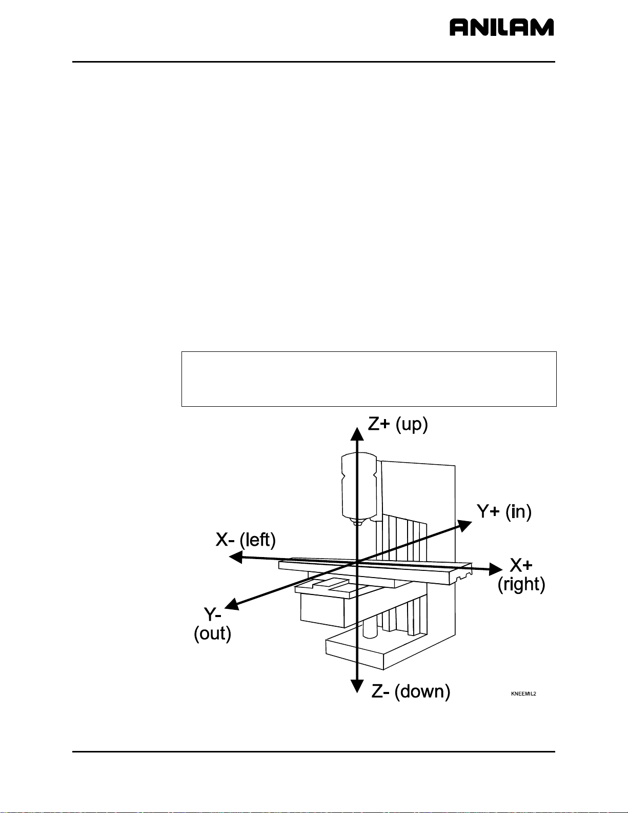
Axis Descriptions
The machine moves along its axes of motion. All movement along an
axis is in either a positive or negative direction. Not all machines use the
same system for identifying axes. The descriptions here are most
commonly used for three axis mills. Refer to Figure 1-1.
NOTE: To keep directions straight when programming machine
movements, consider tool motion rather than table motion.
(When tool motion is positive, table motion in negative, and vice
versa.)
Figure 1-1, Mill Axes of Motion (Tool Motion Orientation)
All rights reserved. Subject to change without notice. 1-1
November 2009
Page 12
CNC Programming and Operations Manual
P/N 70000504I - CNC Programming Concepts
X Axis
The table moves left and right along the X-axis. Positive motion is table
movement to the left (tool, right); negative motion is table movement to
the right (tool, left).
Y Axis
The table moves in and out along the Y-axis. Positive motion is table
movement out (tool, in); negative motion is table movement in (tool, out).
Z Axis
In the Z-axis, the tool moves up and down on the spindle. Positive motion
is tool movement up; negative motion is tool movement down (into the
work).
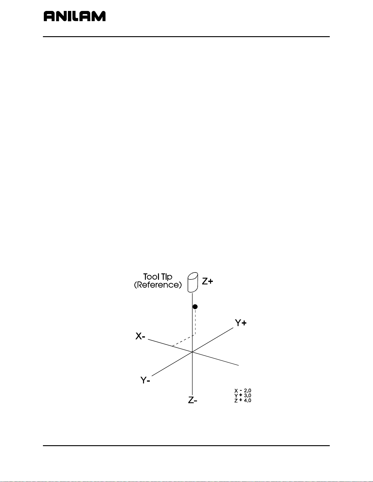
Defining Positions
The intersection of the X, Y, and Z-axes is the reference point that defines
most positions. This point is the X0, Y0, and Z0 position. Refer to
Figure 1-2.
Most positions are identified by X, Y, and Z coordinates. A position two
inches left, three inches back, and four inches up has the following
coordinates:
X-2.0
Y3.0
Z4.0
+4
+3
-2
X+
Figure 1-2, Locating Positions
1-2 All rights reserved. Subject to change without notice.
November 2009
Page 13
CNC Programming and Operations Manual
A
P/N 70000504I - CNC Programming Concepts
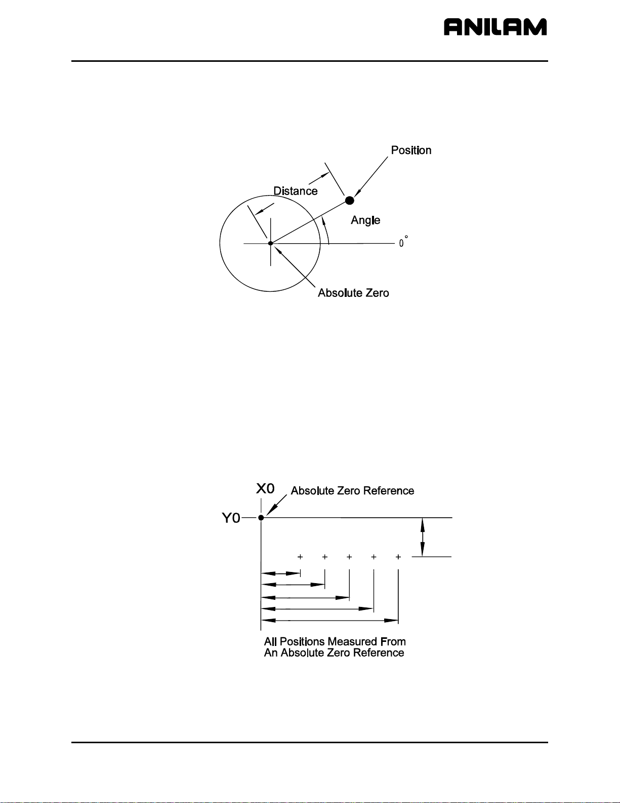
Polar Coordinates
Polar Coordinates define points that lie on the same plane. Polar
coordinates use the distance from the origin and an angle to locate
points. Refer to
Figure 1-3.
POLAR
Figure 1-3, Polar Coordinate System
Absolute Positioning
In the Absolute Mode, all positions are measured from the Absolute Zero
Reference point. Absolute Zero is not a fixed position on the machine,
but a point you select. Refer to
You can set the Absolute Zero Reference point (X0, Y0) anywhere.
Usually the Absolute Zero Reference is set at a position that makes it
easy use the dimensions from the blueprint. This is also called setting the
Part Zero.
Figure 1-4.
BSOLUTE
Figure 1-4, Absolute Positioning
All rights reserved. Subject to change without notice. 1-3
November 2009
Page 14
CNC Programming and Operations Manual
P/N 70000504I - CNC Programming Concepts
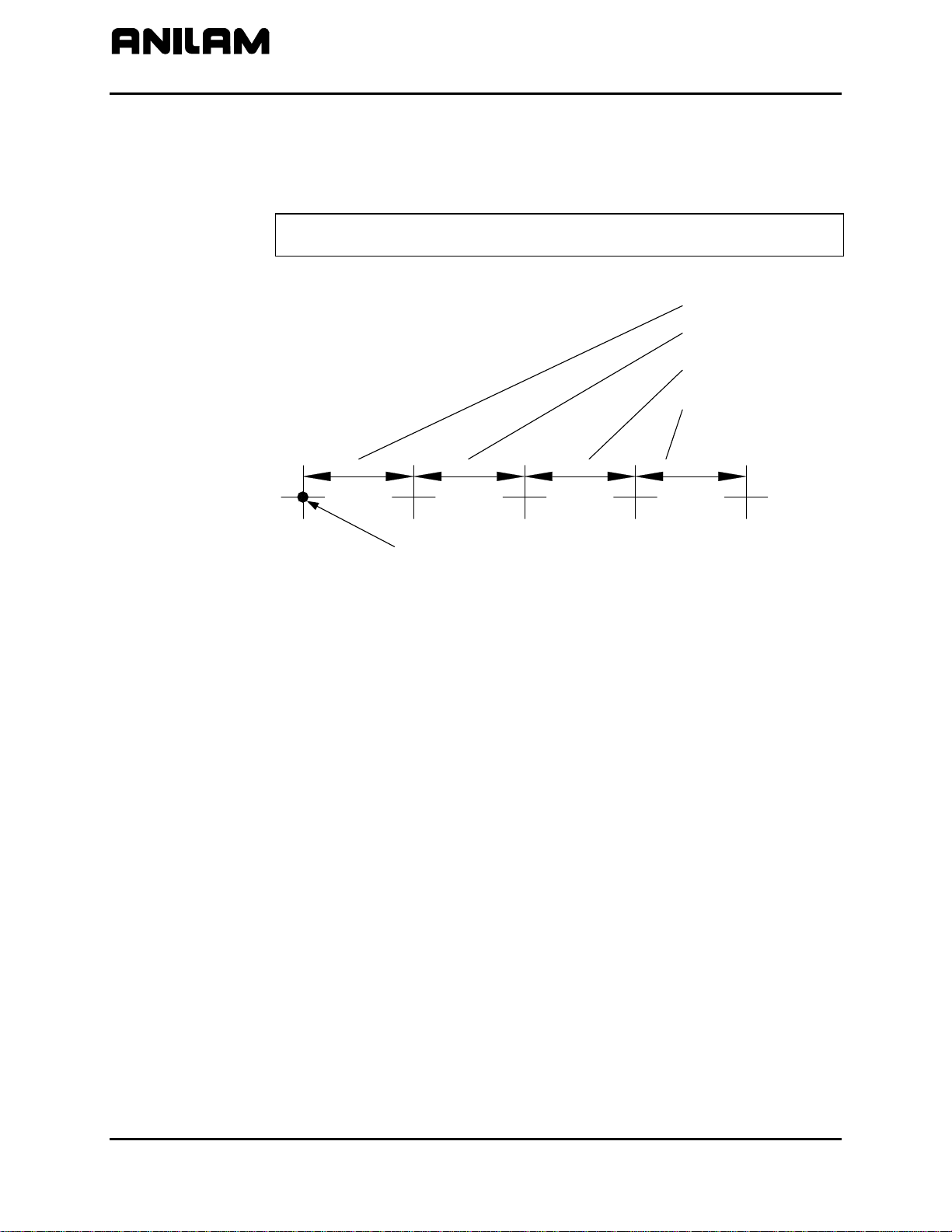
Incremental Positioning
Measure incremental moves from the machine’s present position. This is
convenient for performing an operation at regularly spaced intervals.
Refer to
Figure 1-5.
NOTE: An incremental 0-inch/0-mm move will not make a position
change.
First increment
Second increment
Third increment
Fourth increment
Original Location
Figure 1-5, Incremental Positioning
INCREMENTAL
1-4 All rights reserved. Subject to change without notice.
November 2009
Page 15
CNC Programming and Operations Manual
P/N 70000504I - CNC Programming Concepts
Tool-Length Offsets
The operator sets the Z0 position of the quill, from which the CNC applies
Tool-Length Offsets. Usually it is the fully retracted position of the quill.
NOTE: For machines without homing, it may be necessary to set
machine home to make setting tool-length offsets easier. Either
manually or by jogging take the Z-axis close to the top of travel.
The servo must be turned on. Press MDI (F7), press Mill (F5),
press More (F7), curse down to Home and press ENTER, press Z
the z will light up, press Save, press Prev, press Exit, and press
Start. The Z-axis will change to zero.
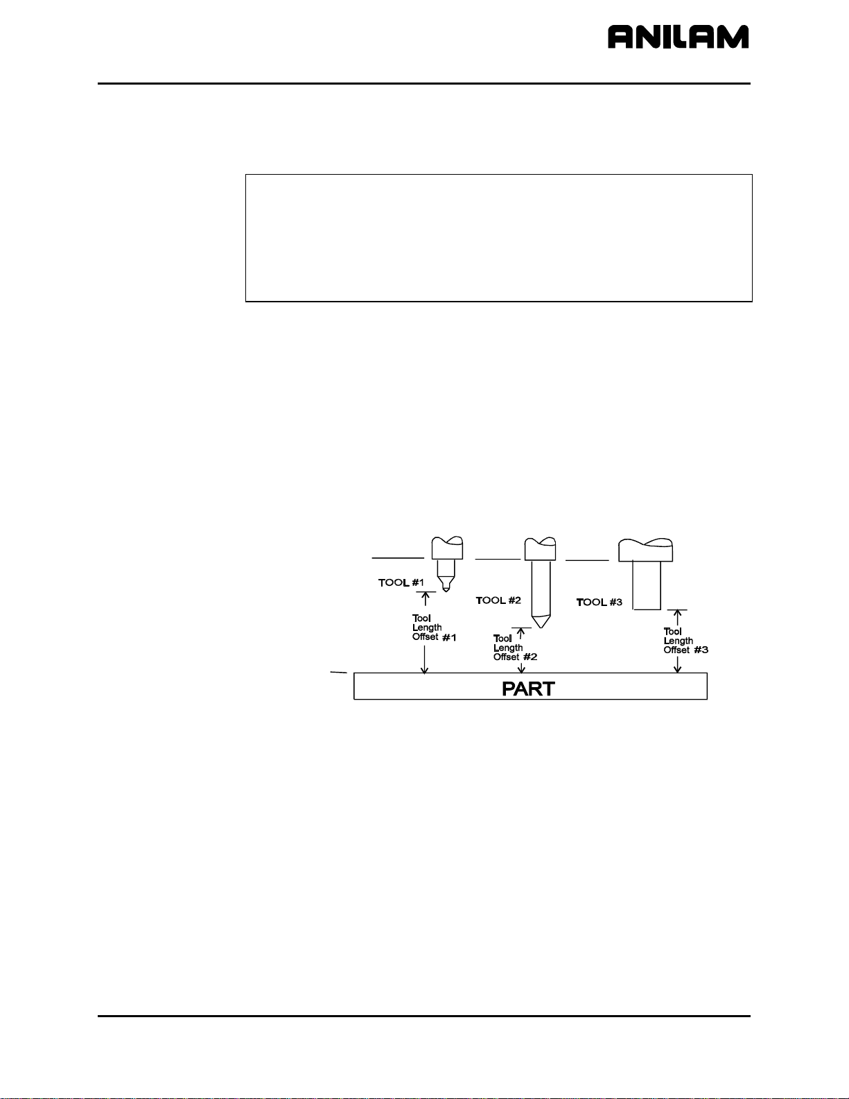
Because tools differ in length, Z0 axis (Part Zero) is not set the same way
as X0 or Y0. The tool-length offset is the distance from the tip of the tool
to the top of the part. Enter a length offset for each tool in the Tool Page.
(Refer to “Section 10 - Tool Management.”)
Tool-length offset is the distance from Z0 Tool #0 to the tip of the tool at
the part Z0 (usually the surface of the work). Refer to
Figure 1-6.
With tool-length offsets active, the Z-axis position display reads 0.00
when the active tool moves to Part Zero. Tool-length offsets simplify
programming. To move to a position 0.5 inch into the work, program a
move to a Z-.5 position.
Tool # 0
Z0.0
PartZero
Figure 1-6, Tool-Length Offset
All rights reserved. Subject to change without notice. 1-5
November 2009
Page 16
CNC Programming and Operations Manual
P/N 70000504I - CNC Programming Concepts
Tool Diameter Compensation
When tool compensation is not active, the CNC positions the tools center
on the programmed path. This creates a problem when programming a
part profile because the cutting edge is half a diameter away from the
path. Use tool diameter compensation to overcome this problem.
NOTE: Be familiar with basic CNC principles before attempting to write
When tool compensation is active, the CNC offsets the tool by half a
diameter to position the cutting edge of the tool on the programmed path.
This allows you to program the coordinates along the part profile without
adjusting the path to compensate for tool diameter.
Most moves can be compensated. Specify right or left compensation.
Right or left refers to the side of the path to which the tool offsets, viewed
from behind the tool as it moves.
NOTE: Tool compensation should be used only with lines and arcs.
compensated moves.
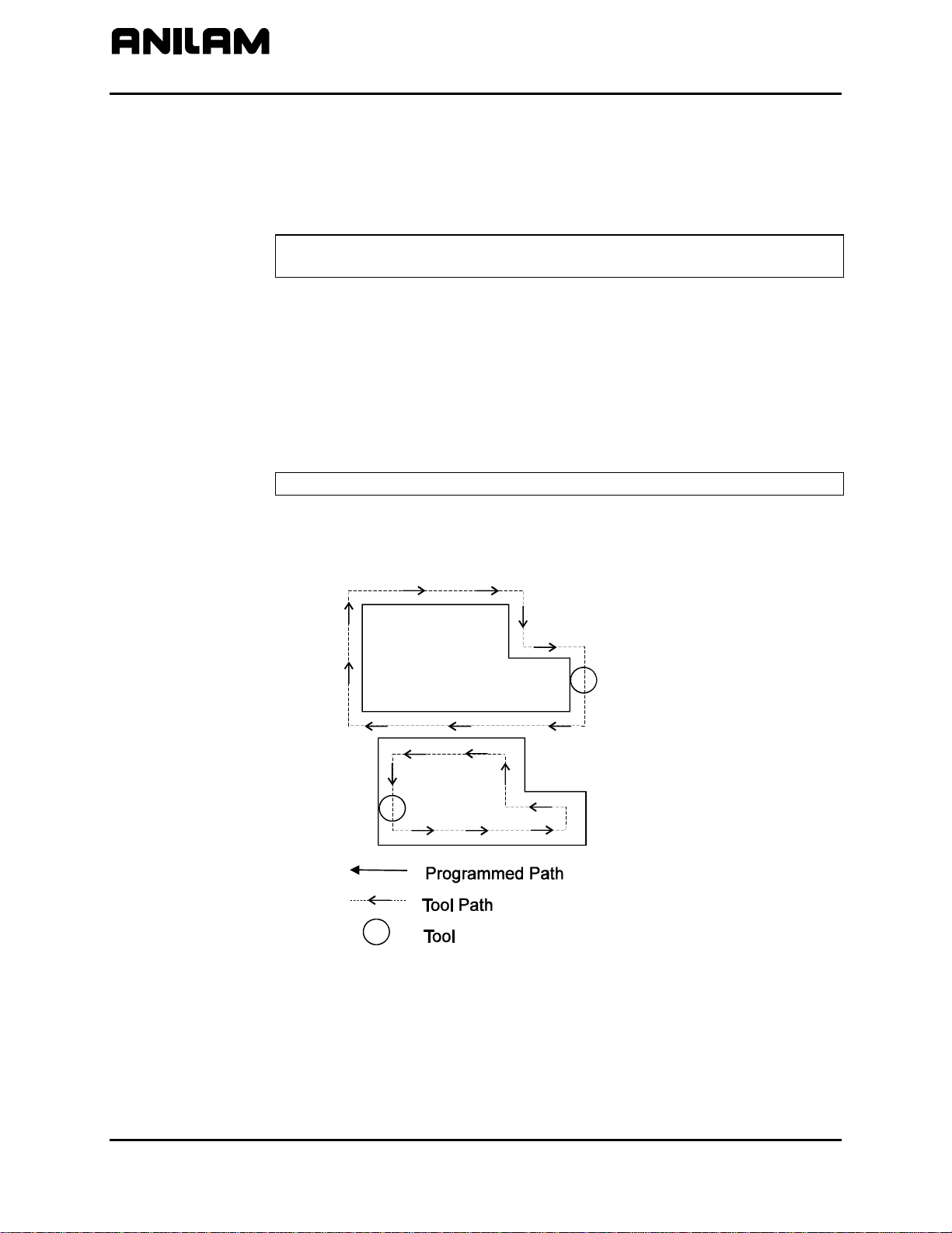
With left-hand tool compensation active, the tool offsets to the left of the
programmed path (looking from behind the tool as it moves). Refer to
Figure 1-7.
LHCOMP
Figure 1-7, Left-Hand Tool Compensation
1-6 All rights reserved. Subject to change without notice.
November 2009
Page 17
CNC Programming and Operations Manual
P/N 70000504I - CNC Programming Concepts
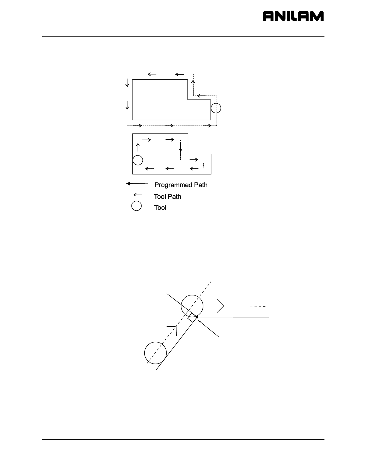
With right-hand tool compensation active, the tool offsets to the right of
the programmed path (looking from behind the tool as it moves). Refer to
Figure 1-8.
RHCOMP
Figure 1-8, Right-Hand Tool Compensation
When the CNC encounters two consecutive, compensated moves, the
tool follows the offset path for the first move until it reaches the offset path
for the second move. Refer to
Figure 1-9. The tool may intersect the
offset path for the second move, either before or after the endpoint of the
first move, depending on the geometry.
Move 2
Tool Path
Move 1
End Point
Move 1
Figure 1-9, Consecutive Compensated Moves
COMP2
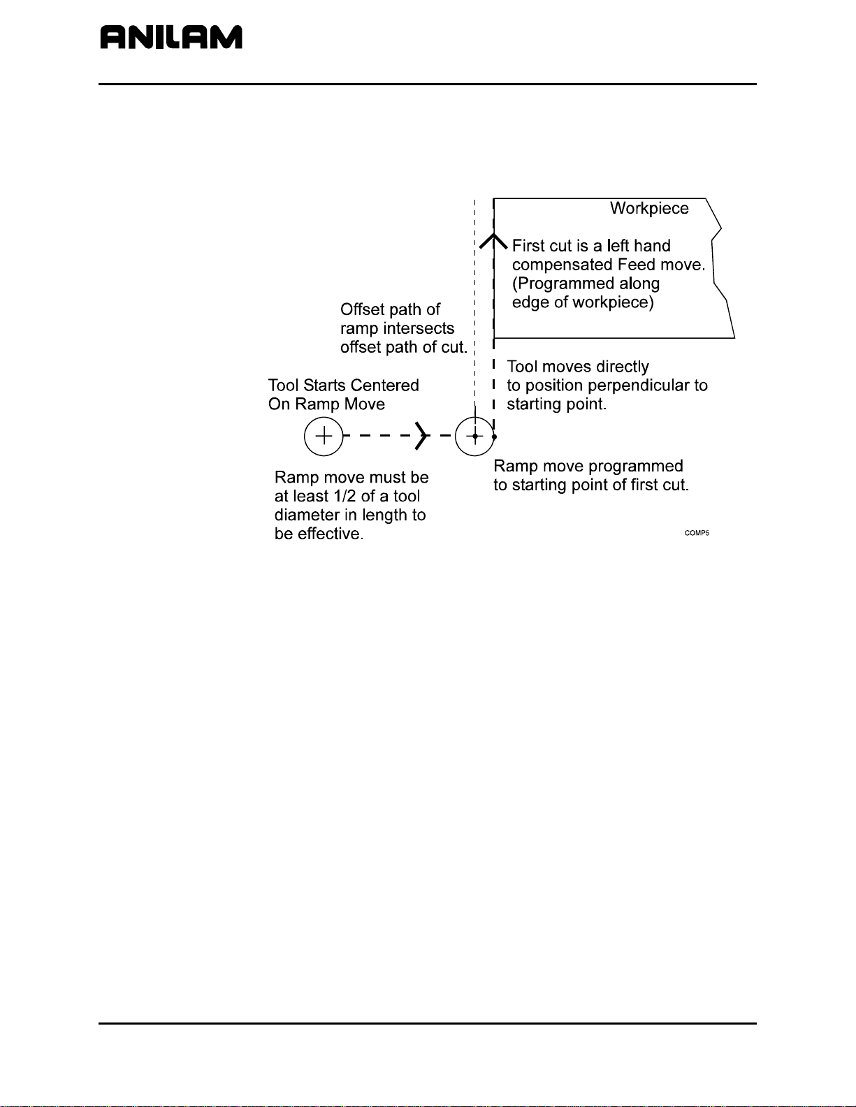
The moves to and from compensated moves are called ramp moves.
Ramp moves give the CNC time to position the tool. The ramp move
must be at least half the active tool’s diameter in length.
All rights reserved. Subject to change without notice. 1-7
November 2009
Page 18
CNC Programming and Operations Manual
P/N 70000504I - CNC Programming Concepts
At the start of a ramp move, the tool centers on the programmed path. At
the end of the ramp move (starting point of the compensated move), the
tool centers perpendicular to the starting point, offset by half the tool’s
diameter. Refer to
Figure 1-10.
Figure 1-10, Ramping into a Compensated Move
Carefully consider how compensation will affect the position of the tool at
the start and end of a move.
1-8 All rights reserved. Subject to change without notice.
November 2009
Page 19
CNC Programming and Operations Manual
P/N 70000504I - CNC Programming Concepts
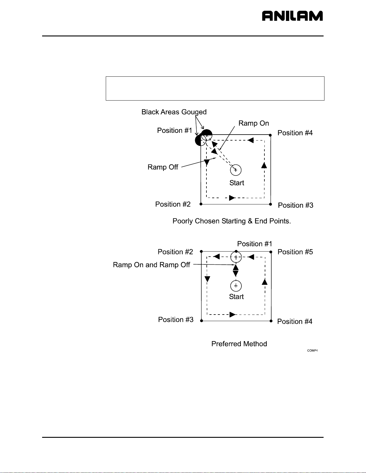
When a compensated move starts and stops in a corner, the tool gouges
the work because the tool offsets to a position perpendicular to the
endpoint. Begin ramp moves at the side to avoid gouging the workpiece.
Refer to
Figure 1-11.
NOTE: Use canned cycles to cut profiles and pockets, when possible.
The CNC automatically selects ramp On/Off positions in a
canned cycle.
Figure 1-11, Ramp On/Off Choices for Milling Inside a Square
All rights reserved. Subject to change without notice. 1-9
November 2009
Page 20
CNC Programming and Operations Manual
Adj
r
pPar
P/N 70000504I - CNC Programming Concepts
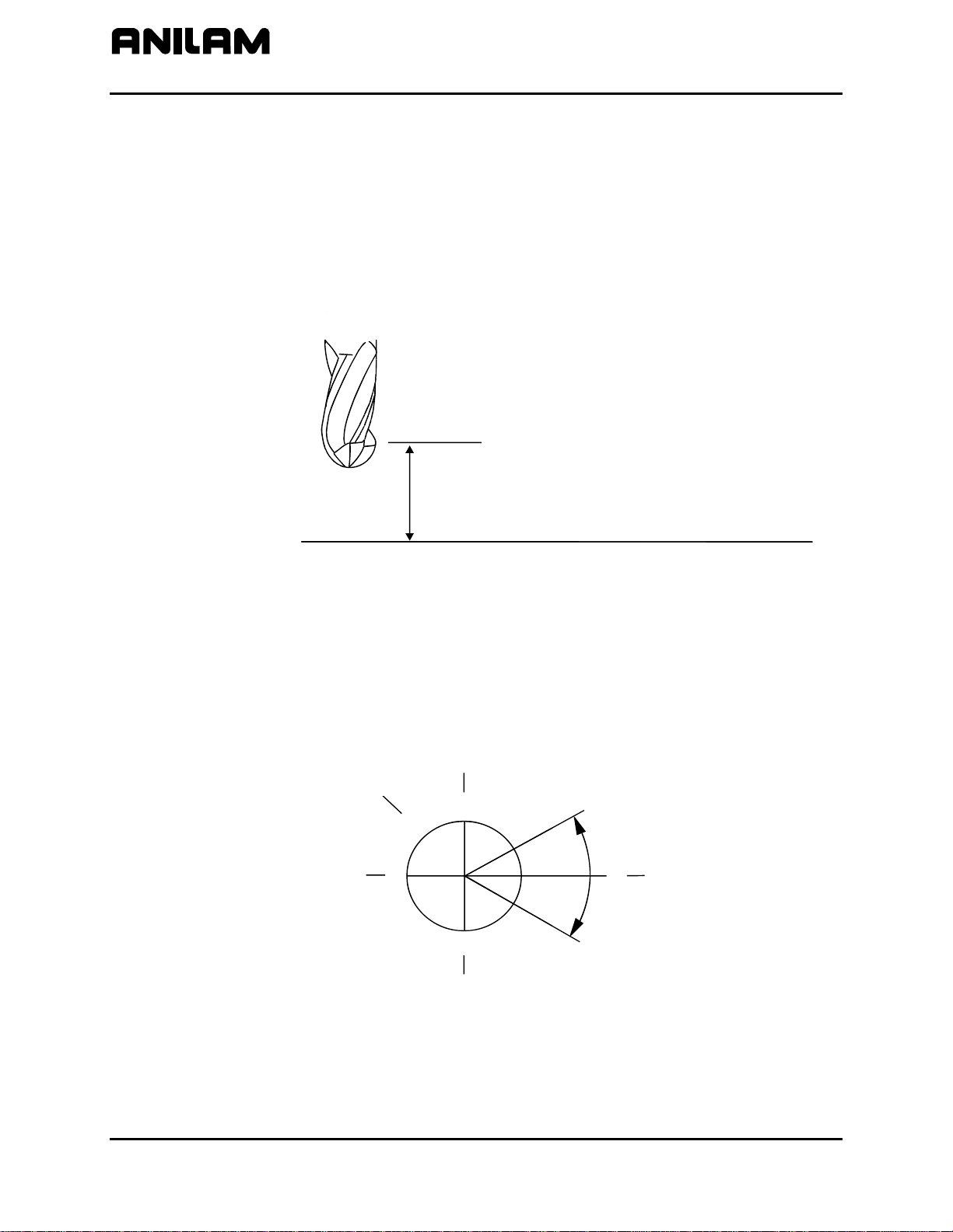
Using Tool Diameter Compensation and Length Offsets with Ball-End Mills
When using a ball-end mill to cut contoured surfaces, use tool diameter
compensation and tool-length offset together, if at all. Unlike an end
cutter, the tool-length offset for a ball-end mill is not set to the tip of the
tool.
Set the tool-length offset for a ball-end mill half the tool’s diameter back
from the tip. Refer to
length offsets, refer to “Section 10 - Tool Management.”
Figure 1-12. For more details on how to set tool-
Angle Measurement
Measure angles from the 3 o’clock position (0 degrees). Positive angles
rotate in a counterclockwise direction; negative angles rotate in a
clockwise direction. Refer to
Ball End Mill
QuillAtTool#0,Z0Position
1
Tool DiameterFrom Ti
2
Tool Length Offset
ustedToBall'sCente
tZero
Figure 1-12, Setting Tool-Length Offset for Ball End Mill
Figure 1-13.
Clock
Reference
10
9
X-
8
11
7
Y+
12
6
Y-
Positive
Angle
1
2
4
5
3
+30
-
30
°
°
°
0
Negative
Angle
X+
Figure 1-13, Absolute Angle Measurement
1-10 All rights reserved. Subject to change without notice.
November 2009
Page 21
CNC Programming and Operations Manual
P/N 70000504I - CNC Programming Concepts
Corner Rounding
Corner rounding permits the operator to blend the intersection of
consecutive moves.
To activate corner rounding, the operator keys a radius value (positive)
into the
blends the endpoint of the first move with the starting point of the second.
The blend starts where the radius is tangent to the first move, and
extends to where the radius is tangent to the second.
Use corner rounding between two lines or two arcs. Also use corner
rounding between non-tangent line and arc moves.
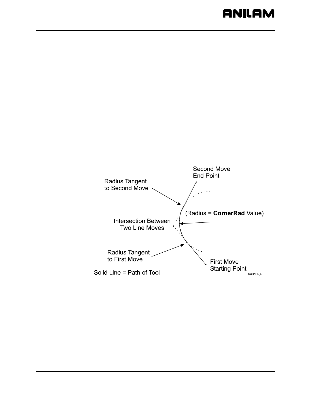
Line-to-Line Corner Rounding
When the first move contains a CornerRad value, the CNC
automatically finds the radius center and the tangent points necessary
to calculate the tool path. The resulting tool path follows the solid line.
Refer to
CornerRad field of the first move. When the program runs, it
Figure 1-14.
Figure 1-14, Line-to-Line Corner Rounding
All rights reserved. Subject to change without notice. 1-11
November 2009
Page 22
CNC Programming and Operations Manual
P/N 70000504I - CNC Programming Concepts
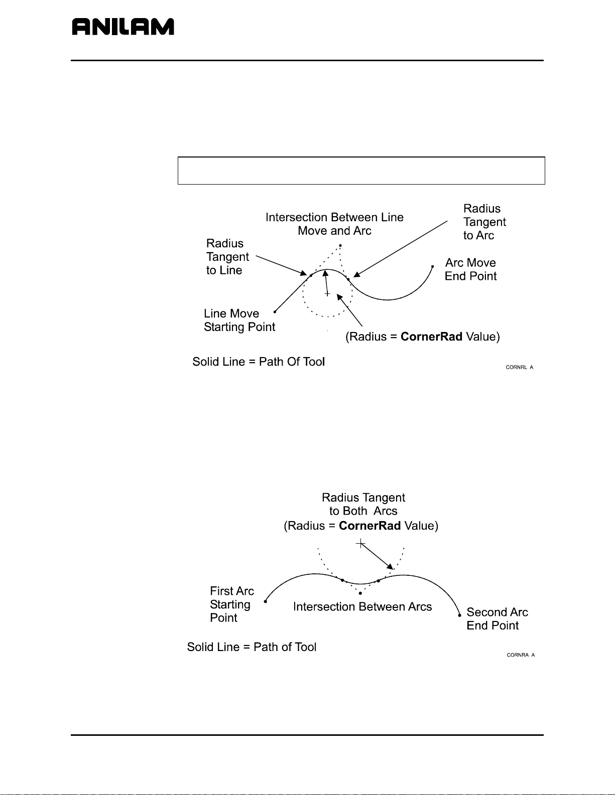
Line-to-Arc Corner Rounding
When the first move contains a CornerRad value, the CNC
automatically finds the radius center and the tangent points necessary
to calculate the tool path. The resulting tool path follows the solid line.
Refer to
Figure 1-15.
NOTE: If the line move is already tangent to the arc move, the CNC
ignores corner rounding.
Figure 1-15, Line-to-Arc Corner Rounding
Arc-to-Arc Corner Rounding
When a CornerRad value is programmed into the first move, the CNC
automatically finds the radius center and the tangent points necessary to
calculate the tool path. The resulting tool path follows the solid line.
Refer to
Figure 1-16.
Figure 1-16, Arc-to-Arc Corner Rounding
1-12 All rights reserved. Subject to change without notice.
November 2009
Page 23
CNC Programming and Operations Manual
P/N 70000504I - CNC Programming Concepts
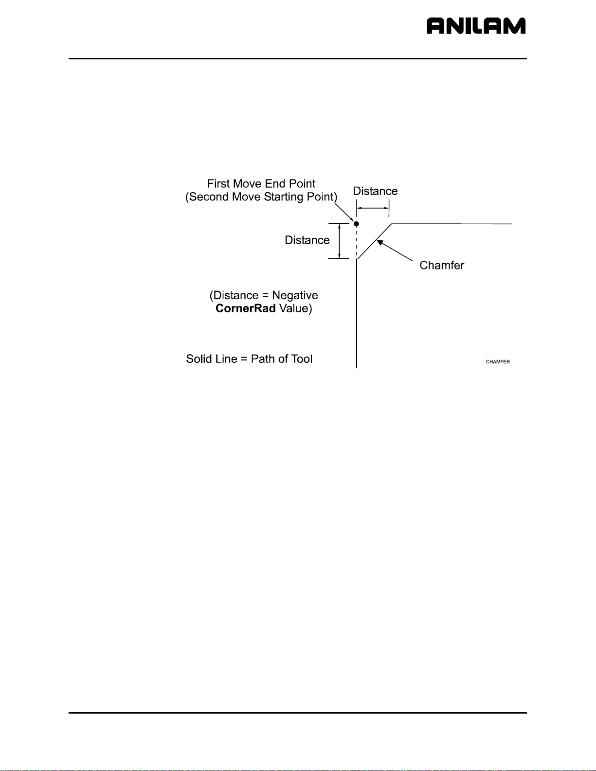
Chamfering
Chamfer between two consecutive line moves. A chamfer starts at a
specified distance before the endpoint of the first move and ends the
same distance from the starting point of the second move. To program a
chamfer move, enter a negative value into the
move. The entered value is the chamfer distance. The resulting tool path
follows the solid line. Refer to
Figure 1-17.
CornerRad field of the first
Figure 1-17, Chamfering
All rights reserved. Subject to change without notice. 1-13
November 2009
Page 24
CNC Programming and Operations Manual
P/N 70000504I - CNC Programming Concepts
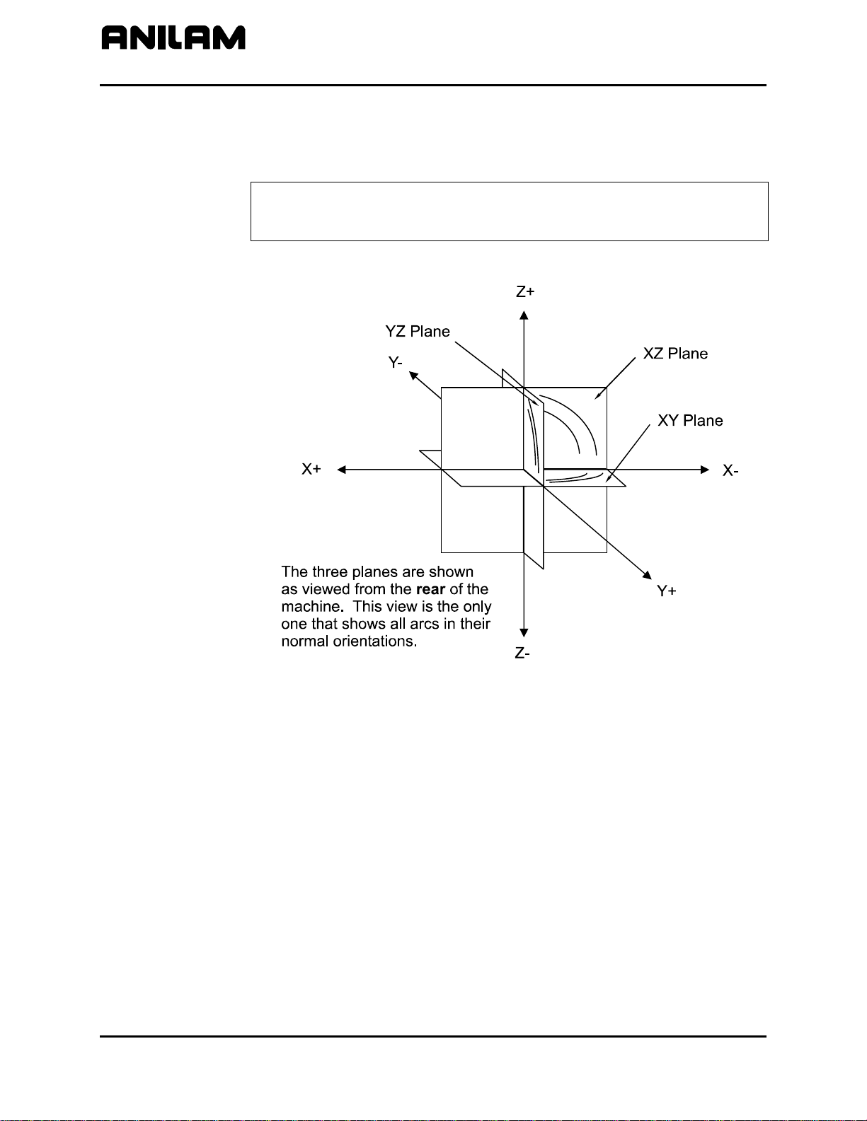
Plane Selection
Circular moves and tool diameter compensation are confined to the plane
you select (XY, XZ, or YZ).
CAUTION: A plane viewed from the wrong side causes arc
directions, angle references, and axis signs to appear
Refer to Figure 1-18 for a description of the three available planes.
reversed.
Figure 1-18, Plane Identification
1-14 All rights reserved. Subject to change without notice.
November 2009
Page 25
CNC Programming and Operations Manual
P/N 70000504I - CNC Programming Concepts
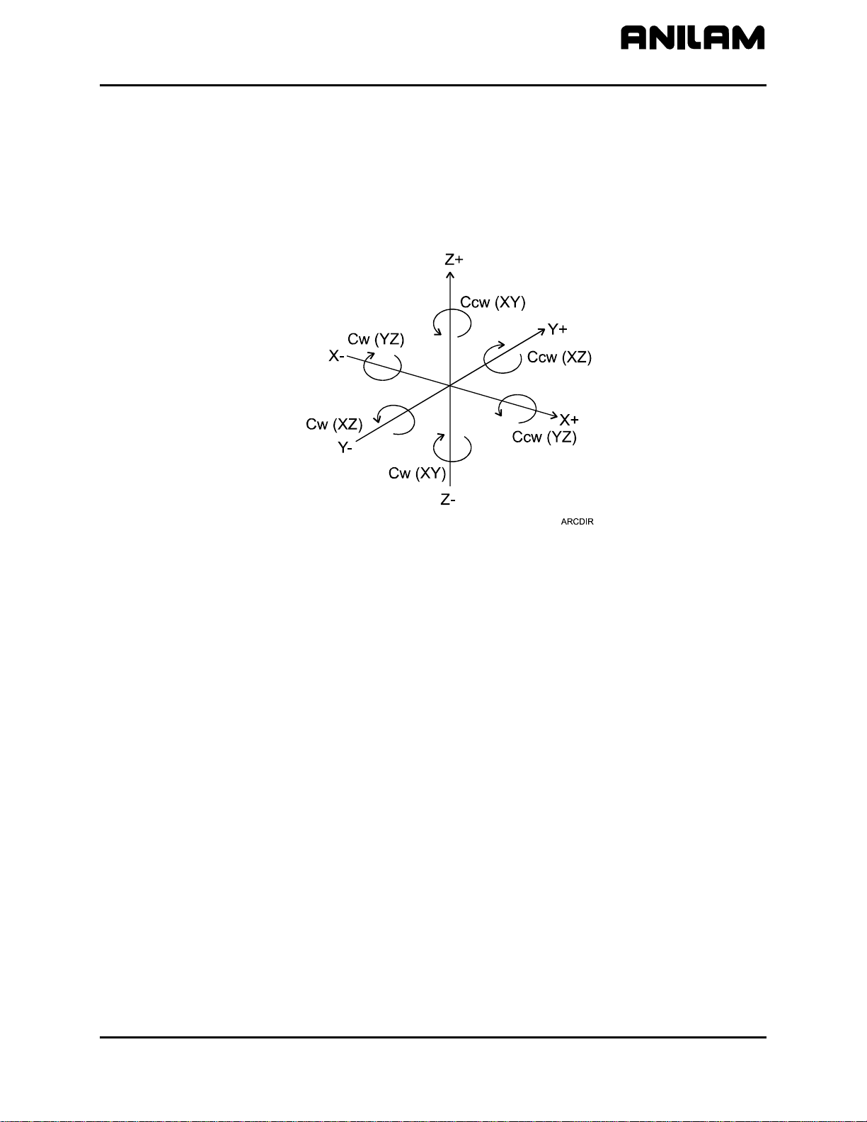
Arc Direction
The standard rule is to view arc direction for a plane from the positive
toward the negative direction along the unused axis. From this viewpoint
clockwise (Cw) and counterclockwise (Ccw) arc directions can be
determined. For example, in the XY plane, you view along the Z-axis,
from Z+ toward Z-, to determine Cw/Ccw directions. The Cw/Ccw arc
directions for each plane are shown in
Figure 1-19.
Figure 1-19, Clockwise and Counterclockwise Arc Directions
All rights reserved. Subject to change without notice. 1-15
November 2009
Page 26

Page 27
CNC Programming and Operations Manual
P/N 70000504I - CNC Console And Software Basics
Section 2 - CNC Console and Software Basics
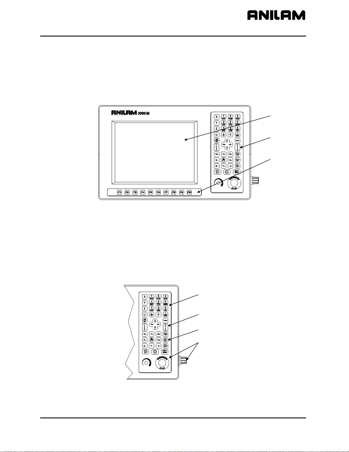
Console
The CNC console consists of a 12.1” color, flat-panel Liquid Crystal
Display (LCD), a keypad to the right of the monitor, and soft keys
below the monitor. Refer to Figure 2-1.
LCD
Keypad
Soft Keys
Keypad
3000M CONSOLE
Figure 2-1, CNC Console
Refer to Figure 2-2. The keypad to the right of the monitor has four
types of keys:
Programming Hot Keys
Editing Keys
Manual Operation Keys
Operator Keys
Programming
Hot Keys
Editing
Keys
Manual Operation Keys
Operator Keys
(with SPINDLE OVERRIDE)
3000M KEYPAD
Figure 2-2, Keypad
All rights reserved. Subject to change without notice. 2-1
November 2009
Page 28
CNC Programming and Operations Manual
y
P/N 70000504I - CNC Console And Software Basics
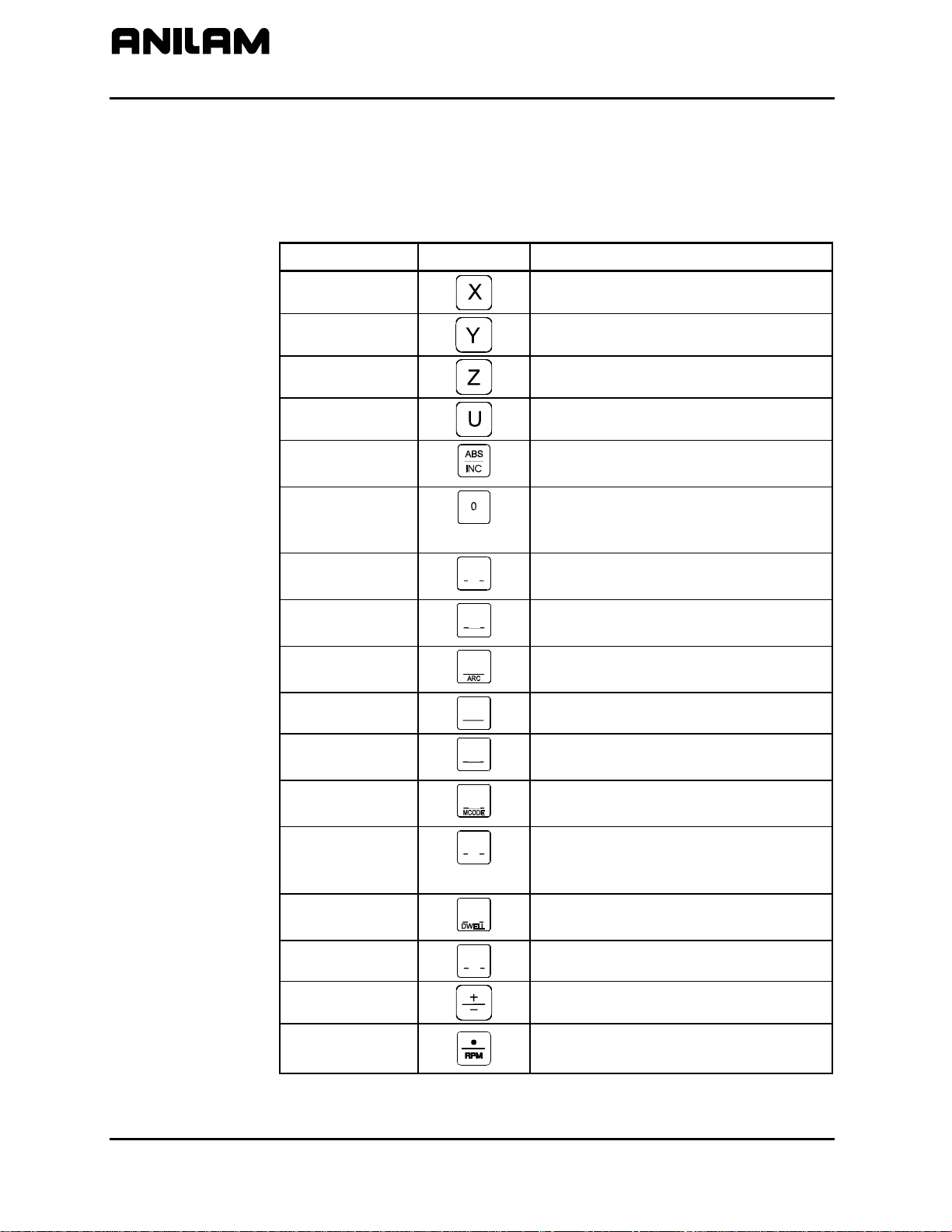
Programming Hot Keys
Programming hot keys allow you to enter position coordinates and
provide quick access to functions that speed up programming. They
are active in the Edit and Manual Mode. Refer to Table 2-1.
Table 2-1, Programming - Hot keys
Label or Name Key Face Purpose X
Selects X-axis for position inputs.
Y
Z
U
ABS/INC
0
1/RAPID
2/LINE
3/ARC
4/FEED
5/TOOL
1
RAPID
2
LINE
3
4
FEED
5
TOOL
Selects Y-axis for position inputs.
Selects Z-axis for position inputs.
Selects U-axis for position inputs.
Switches CNC between Absolute and
Incremental Modes.
Zero / Switches comment asterisk in
edit mode. Switches resolution displa
between program and Dist. To Go.
One / Hot key for programming a
Rapid move.
Two / Hot key for programming a
Line move.
Three / Hot key for programming an
Arc.
Four / Hot key for changing feedrate.
Five / Hot key for programming a
tool.
6/MCODE
7/UNIT
6
7
UNIT
Six / Hot key for programming an Mcode.
Seven / Hot key for switching
between inches (Inch) and
millimeters (mm).
8/DWELL
9/PLANE
+/-
DECIMAL/RPM
8
9
PLANE
Eight / Hot key for programming a
Dwell.
Nine / Hot key for selecting a plane.
Sign change / Toggle hot key.
Decimal point / Hot key for
programming the spindle RPM.
(Continued…)
2-2 All rights reserved. Subject to change without notice.
November 2009
Page 29
CNC Programming and Operations Manual
P/N 70000504I - CNC Console And Software Basics
Table 2-1, Programming - Hot keys (Continued)
Label or Name Key Face Purpose
CALC
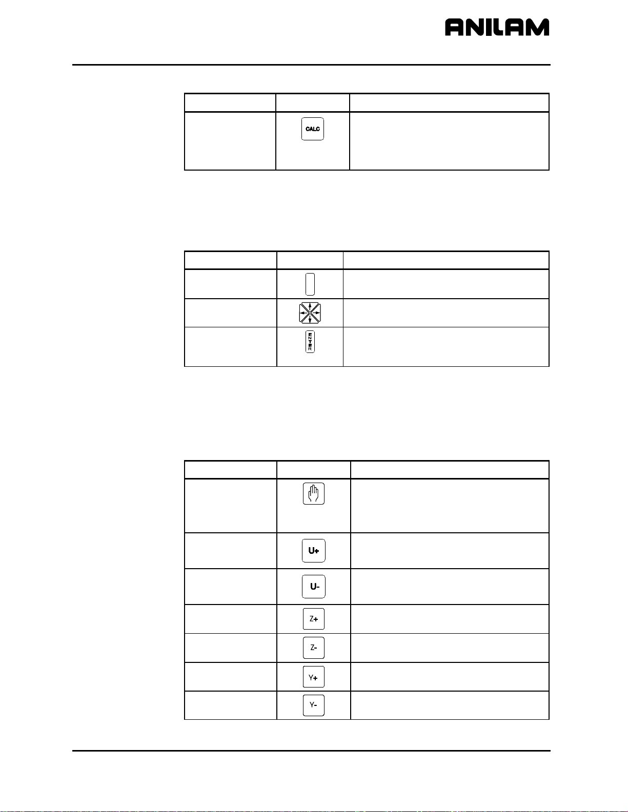
Editing Keys
Editing keys allow you to edit program blocks. These keys are located
below the Programming Hot Keys. Refer to Table 2-2.
Table 2-2, Editing Keys
Label or Name Key Face Purpose
CLEAR
ARROW
ENTER
Manual Operation Keys
Manual Operation Keys allow you to control machine movements
manually. These keys are located below the Editing Keys. Refer to
Table 2-3.
Calculators / Hot key to display the
Select Type of Calculator: pop-up
menu. See Figure 12-1, Calculator
Selection Menu.
C L E A R
Clears the selected messages, values,
commands, and program blocks.
Allows you to move highlight bars and
cursor around the screen.
Selects blocks for editing, activates
menu selections, activates number
entry, or presets XYZ positions.
Table 2-3, Manual Operation Keys
Label or Name Key Face Purpose
JOG
Cycles the CNC through manual
movement modes (JOG: RAPID,
JOG: FEED, JOG: 100, JOG: 10,
JOG: 1).
U+
Manually moves machine in positive
U direction.
U-
Manually moves machine in negative
U direction.
Z+
Z-
Y+
Y-
Manually moves machine in positive
Z direction.
Manually moves machine in negative
Z direction.
Manually moves machine in positive
Y direction.
Manually moves machine in negative
Y direction.
(Continued…)
All rights reserved. Subject to change without notice. 2-3
November 2009
Page 30
CNC Programming and Operations Manual
P/N 70000504I - CNC Console And Software Basics
Table 2-3, Manual Operation Keys (Continued)
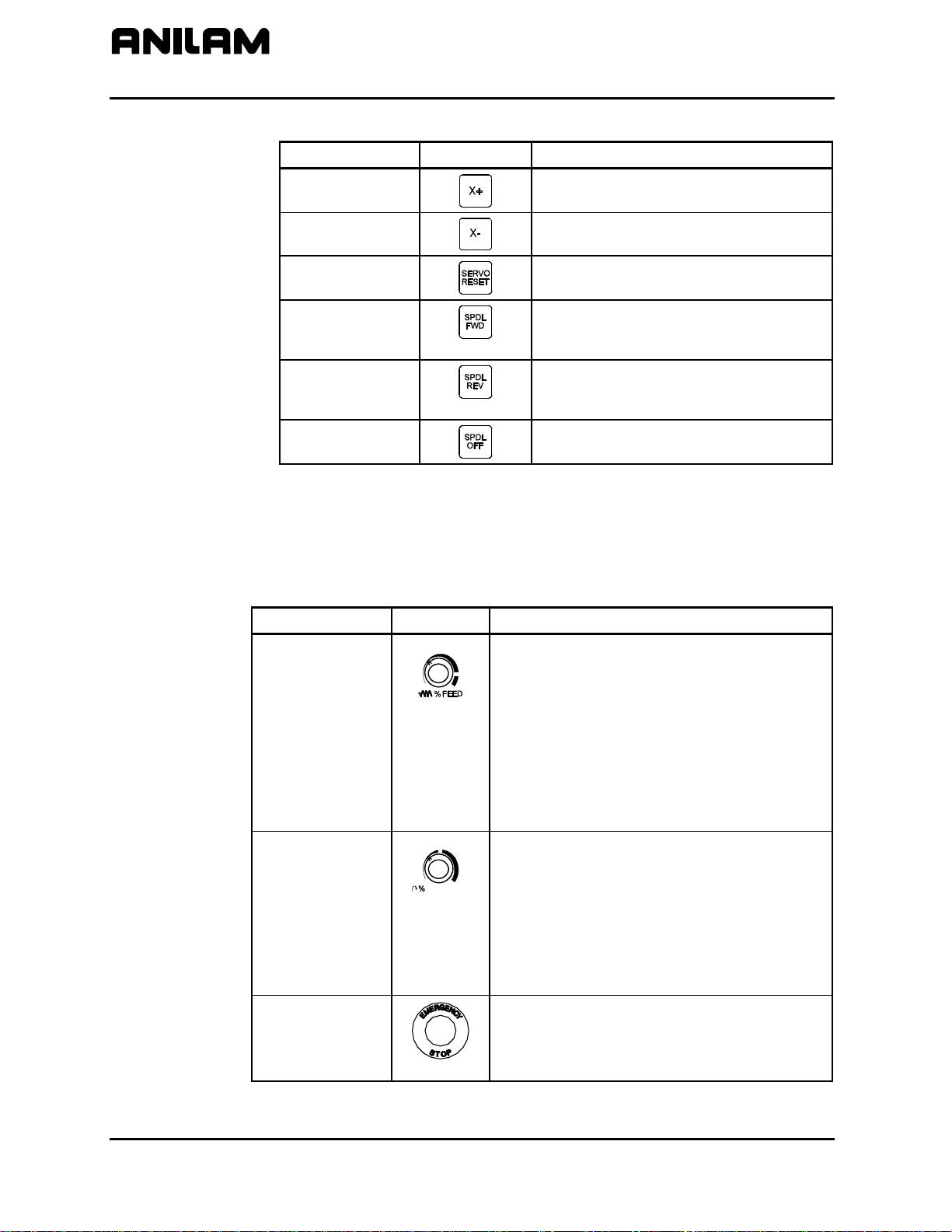
Operator Keys
Table 2-4, Operator Keys
Label or Name
X+
X-
SERVO RESET
Key Face Purpose
Manually moves machine in positive
X direction.
Manually moves machine in negative
X direction.
Activates servo motors.
SPINDLE
FORWARD
Starts spindle in a clockwise direction
(viewed from the top of the motor).
Optional.
SPINDLE
REVERSE
Starts spindle in a counterclockwise
direction (viewed from the top of the
motor). Optional.
SPINDLE OFF
Stops the spindle.
Operator Keys allow you to control machine movements manually.
These keys are located below the Manual Operation Keys and on the
right side panel of the CNC console. Refer to Table 2-4.
Label or Name Key Face Purpose
FEEDRATE
OVERRIDE
Overrides the feed and/or rapid rate of the
axes in Manual, Auto, and Single Step
modes. It is a 13-position rotary switch,
which ranges from 0 to 120 percent.
(Each increment adjusts the feedback
override by 10%.)
NOTE: The override range for rapid rate is
100%. The CNC will not exceed the
maximum rapid rate.
SPINDLE
OVERRIDE
SPINDLE
Typically on the right side panel of the
CNC console. Overrides the programmed
spindle RPM rate. It is a 13-position rotary
switch that ranges from 40 to 160 percent.
(Each increment adjusts the spindle
override by 10%.) This feature can be
used only on machines with programmable
spindles.
E-STOP
The red emergency stop button
disconnects the machine’s servos,
stopping the spindle and all machine
movement.
(Continued…)
2-4 All rights reserved. Subject to change without notice.
November 2009
Page 31

CNC Programming and Operations Manual
P/N 70000504I - CNC Console And Software Basics
Table 2-4, Operator Keys (Continued)
Label or Name Key Face Purpose
START
HOLD
The green
moves except jog.
The red
program or programmed move. (Press
START to resume.)
START key initiates all machine
HOLD key pauses any running
Soft Keys (F1) to (F10)
The soft keys (function keys) located just below the monitor are labeled
(F1) through (F10). Soft key functions are not hard-wired but change in
various modes. Active soft keys are labeled on screen. Inactive soft
keys remain blank.
Off-line Keyboard (Optional)
The CNC supports most standard PC keyboards. Refer to “Section 13 Off-line Software.” All keypad inputs except
are available on a keyboard.
E-STOP and SERVO RESET
Software Basics
Pop-up Menus
The CNC’s screens change as different modes are activated. Basic
procedures and features of the software remain the same, regardless of
the CNC’s mode.
Pop-up menus are temporary menus that allow you to make additional
selections. Refer to Figure 2-3. Each pop-up menu contains a highlight
bar. The
ENTER to activate the highlighted selection. Press the soft key that
activated it or press
ARROWS move the highlight bar up and down the menu. Press
CLEAR to close a pop-up menu.
POPUP3X
Figure 2-3, Pop-up Menu
All rights reserved. Subject to change without notice. 2-5
November 2009
Page 32

CNC Programming and Operations Manual
P/N 70000504I - CNC Console And Software Basics
Screen Saver
After a set period of inactivity, the CNC’s screen dims to preserve the
LCD. Press any key to restore the CNC to a ready status.
Switching Selections with the Toggle Key
Press the +/- key (toggle key) to toggle between options. (For example:
Cw/Ccw, ToolComp.) This key also produces the negative symbol.
Clear Key
Press
a message on the message line.
Operator Prompts
The CNC prompts when it requires specific information. When the CNC
prompts for a text entry, use the ASCII Chart to enter ASCII characters
from the keypad. Refer to “ASCII Chart” for more information. Enter
numbers from the keypad.
ASCII Chart
When the CNC prompts for a text entry, the ASCII (F2) soft key is
displayed. Press ASCII (F2) to toggle the ASCII Chart On and Off. The
ASCII Chart allows you to enter text from the keypad. Refer to
Figure 2-4.
CLEAR to clear an entry in an entry field, a line from a program, or
ASCII
Figure 2-4, ASCII Chart Pop-up
Using the
ENTER key to display the character in the prompt area. Turn off the
ASCII Chart, and press
2-6 All rights reserved. Subject to change without notice.
November 2009
ARROW keys, select the character you want to enter. Press the
ENTER to complete the text entry.
Page 33

CNC Programming and Operations Manual
P/N 70000504I - CNC Console And Software Basics
Cursor and Highlight Functions
The CNC uses either a cursor or highlight to mark an item for selection
or editing.
The highlight is displayed in the Edit Mode, Program Directory, Manual
mode, and ASCII Chart. Use the
ARROWS to move the highlight. The
software highlights a selected item in a menu or window. Selected items
can be activated or changed in some way. For instance, you highlight a
program block in Edit Mode to edit it. You highlight an entry field label in
a Graphic Menu to enter a value or switch between the available
choices.
The cursor is displayed when the Tool Page activates. The cursor is a
white underline that indicates where letters and numbers will be inserted.
Entering Text
Use the ASCII Chart or a keyboard to enter text.
To enter text using the ASCII (F2) chart:
1. Press ASCII (F2). ASCII Chart activates.
2. Highlight desired character.
3. Press
ENTER. The CNC displays the selected character at the
cursor.
4. Select all required characters.
5. Press ASCII (F2) to close the ASCII Chart.
Typing Over and Inserting Letters and Numbers
The ASCII Chart has two text entry modes: Typeover (default) and
Insert.
In the Typeover Mode, new characters replace characters marked by the
cursor.
In the Insert Mode, new characters appear at the cursor and existing
characters move to the right. When the Insert Mode is active, Ins (F3)
highlights.
To put the CNC in the Insert Mode:
1. When the CNC prompts for a name, press Ins (F3). Ins (F3)
highlights.
All rights reserved. Subject to change without notice. 2-7
November 2009
Page 34

CNC Programming and Operations Manual
P/N 70000504I - CNC Console And Software Basics
Deleting Characters
To delete characters:
1. With the ASCII Chart active, move the cursor to underline the
character being deleted.
2. Press Del (F4). The selected character disappears.
NOTE: Press
Messages/Error Messages
Messages generated by the CNC appear in the message area, present
in all program-running modes. Refer to Figure 2-5. When the CNC
generates more than one message, the message with the highest priority
is displayed in the message area. Lower-priority messages remain in
memory. The on-screen MESSAGE label highlights when pending
messages remain in memory. There are two ways to review pending
messages:
Press CLEAR. The CNC clears the current message and displays the
next message.
From the Manual screen, press MESSAGE (F1). Displayed
messages appear in the Program Area of the screen.
Some messages are advisory; others stop CNC operation. For those
that stop operation, you must put the CNC in the Manual Mode to correct
the problem, and then clear the message.
CLEAR to delete an entire word.
% :
100
Figure 2-5, Messages Display
2-8 All rights reserved. Subject to change without notice.
November 2009
Page 35

CNC Programming and Operations Manual
P/N 70000504I - Manual Operation and Machine Setup
Section 3 - Manual Operation and Machine Setup
Powering On the CNC
To power on the CNC:
1. Press the power switch on the CNC cabinet. The CNC activates the
startup screen and prompts you to Press F10 to continue.
2. Press C
3. Highlight CNC Control, and press
Shutting Down the CNC
To shut down the CNC:
1. Press
2. Press EXIT (F10) to display the Software Options menu.
3. Press the power switch on the CNC cabinet to power down the CNC.
Emergency Stop (E-STOP)
Use E-STOP to take all axes and spindle servos offline and halt machine
movement.
To reset
1. Rotate the E-STOP switch in the direction of the arrows. The switch
clicks when reset. The CNC does not automatically reactivate the
servos after an
machine or start the spindle.
2. Press
ONT. (F10) to display the Software Options menu.
ENTER to activate Manual Mode.
E-STOP to disengage the Servos and activate Manual Mode.
E-STOP:
E-STOP reset. You must reset the servos to move the
SERVO RESET to reset the servos.
Performing an Emergency Stop
To perform an emergency stop:
1. Press
NOTE: You cannot activate E-STOP using an off-line keyboard.
All rights reserved. Subject to change without notice. 3-1
November 2009
E-STOP to disengage the servos and activate Manual Mode.
Page 36

CNC Programming and Operations Manual
P/N 70000504I - Manual Operation and Machine Setup
Activating/Resetting the Servos
For safety reasons, the CNC powers up with the servo motors off. With
the servos turned off, the CNC cannot move the machine and the spindle
will not start. The CNC displays the SERVO OFF! message when the
servos are off. Refer to “Section 2 - CNC Console and Software Basics”
for reviewing messages.
During operation, press
automatically turn off if the machine attempts to power past a limit switch.
To reset the servos:
1. After a limit switch has been tripped, the servos turn off. Manually
reposition the machine inside its range of travel.
2. Press
3. Rotate the switch in the direction of the arrows to reset
switch clicks when reset.
4. Press
NOTE: You cannot activate the servos using an off-line keyboard.
(Re-)Starting the Spindle
SPINDLE FORWARD and SPINDLE REVERSE do not work if E-STOP is active or
if the servos go off-line.
To (re-)start the spindle:
1. Reset
2. Press
E-STOP to turn off the servos. Servos
E-STOP.
E-STOP. The
SERVO RESET to reset the Servos.
E-STOP.
SERVO RESET.
3. Press either
3-2 All rights reserved. Subject to change without notice.
November 2009
SPINDLE FORWARD or SPINDLE REVERSE, as required.
Page 37

CNC Programming and Operations Manual
P/N 70000504I - Manual Operation and Machine Setup
Manual Mode Screen
The Manual Mode screen is the main CNC screen. All other operating
screens activate from the Manual Mode screen. In Manual Mode, the
MANUAL (F4) soft key label highlights. Refer to Figure 3-1.
Figure 3-1, Manual Mode Screen
The Manual Mode screen features:
Position Display
Machine Position Display
Displays X, Y, and Z position coordinates.
Displays the axis positions in reference to
Machine Home. (Not shown when Draw
activates.)
Secondary Display Area
Primary Display Area
Displays essential operating information.
Displays additional operating information.
(Not shown when Draw activates.)
Message Area
Displays messages, prompts, and
reminders.
Soft Key Labels
Identify the function of the soft key directly
underneath. Labels change from screen
to screen. A highlighted label indicates
an active mode.
Program Listing
Displays program blocks as they run in
Auto or S.Step Mode.
Soft Key Labels
All rights reserved. Subject to change without notice. 3-3
November 2009
Page 38

CNC Programming and Operations Manual
P/N 70000504I - Manual Operation and Machine Setup
Primary Display Area Labels
BLOCK:
TOOL:
FEED:
POSN:
DIA:
%:
Secondary Display Area Labels
PROGRAM
MANUAL/AUTO/S.STEP
IN-POSN
ABS/INC
INCH/MM
HALTED/*HALTED/
RUNNING
Current program block number.
Active tool.
Current feedrate.
Position Display Mode (Program or
Distance to Go).
Active tool diameter.
Feedrate override setting (0% to 120% for
Feed moves, 0% to 100% for Rapid
moves).
Name of selected program.
Current operating mode.
Indicates whether the machine has
reached target (in-posn) or not.
Current positioning mode.
Current units mode.
HALTED (without asterisk) indicates
machine is in a programmed hold, or has
completed its program.
*HALTED (with
asterisk) indicates hold was activated by
an event, or
HOLD was pressed. RUNNING
indicates normal program run.
FEED/RAPID/ARC:
LOOP:
Current move mode.
Number of loops remaining (when running
a subprogram that has loops).
DWELL:
FIXTURE:
RPM:
Seconds remaining in a dwell.
Active fixture offset number.
Spindle RPM (Optional). May display
programmed RPM or actual RPM. Refer
to builder’s documentation for details.
%:
Spindle override setting (40% to 160%)
Optional.
JOG:
Current jog mode.
SPINDLE: Spindle status (FWD/REV/OFF).
Optional.
COOLANT:
3-4 All rights reserved. Subject to change without notice.
November 2009
Coolant status. Optional.
Page 39

CNC Programming and Operations Manual
P/N 70000504I - Manual Operation and Machine Setup
PARTS:
Counts the number of successfully
completed parts. (Increments by 1 every
time the CNC encounters EndMain in a
program run.) The counter resets to zero
when you start a new program. (Refer to
“Section 8 - Running Programs.”)
Position Display
TIMER: Total program run time from
START to
EndMain execution. If the CNC holds,
the counter pauses until the program
restarts. The counter resets to 0 (zero)
when you start a new program. (Refer to
“Section 8 - Running Programs.”)
Refer to Figure 3-2. The POSN: option sets the CNC to display machine
position in one of two ways:
Program
Position Display shows the
programmed position.
Distance To Go
Position Display shows the remaining
distance to the commanded position.
(DISTTOGO)
To switch the P
OSN: setting:
1. In Manual, S. Step, or Auto Mode, press 0 (zero) to switch the setting
between PROGRAM and DISTTOGO.
Soft Key Labels
Figure 3-2, Position Display Options
All rights reserved. Subject to change without notice. 3-5
November 2009
Page 40

CNC Programming and Operations Manual
P/N 70000504I - Manual Operation and Machine Setup
Manual Machine Operation
Two types of manual operation are available:
Manual Mode Digital Readout. Use handles to move the
machine. Servos deactivate.
Auto Mode Control machine using the keypad. Servos move
the machine.
Manual Mode
In DRO Mode, the CNC acts as a digital readout and you use handles to
move the machine.
To activate Manual Mode:
Auto Mode
1. Press
E-STOP.
2. Locate the MANUAL/AUTO switch, usually located on the back of the
console.
3. Set the switch to MANUAL. Servos and spindles disconnect.
4. Reset
5. Press
E-STOP.
SERVO RESET to reactivate the spindle.
To activate Auto Mode:
1. Press
E-STOP.
2. Locate the MANUAL/AUTO switch and move the switch to AUTO.
3. Reset
4. Press
E-STOP.
SERVO RESET. The servos reactivate and the CNC now
operates the machine.
3-6 All rights reserved. Subject to change without notice.
November 2009
Page 41

CNC Programming and Operations Manual
P/N 70000504I - Manual Operation and Machine Setup
Mode Settings
The operator controls every aspect of the CNC’s operation. Settings that
remain active for more than one operation or event are said to be modal.
These settings remain active until changed or turned off.
Many of the CNC’s features are modal. For example, move type (Rapid
or Feed), feedrate (IPM), units (Inch or MM) or ABS/INCR.
The operator should make all of the mode adjustments required for the
machine to move properly before making a manual move. Modes set
from the Manual screen remain active until changed.
Refer to Table 3-1 for the modes/settings from the Manual screen.
Table 3-1, Manual Mode Settings
Mode/Setting Name Choices
Position Mode
Units Mode
Move Mode
Plane
Active Tool
Absolute/Incremental
Inch/Millimeter
Rapid/Feedrate
XY/YZ/XZ
Tool Diameter Compensation and
Tool-Length Offsets
The operator can use the Manual screen to program the locations of the
Absolute Zero Reference (X0, Y0) and the tool change position
(Z0, Tool #0).
The following four types of moves are available in Manual Mode:
Jog (Conventional)
Jog (Continuous)
One Shot Move
Manual Data Input (MDI)
All rights reserved. Subject to change without notice. 3-7
November 2009
Page 42

CNC Programming and Operations Manual
P/N 70000504I - Manual Operation and Machine Setup
Activating Manual Mode Rapid or Feed
Press JOG to switch the Jog Mode. Two Jog Modes (Rapid and Feed)
are CNC move modes. The CNC displays the active Rapid/Feed Mode in
the Secondary Display Area.
Setting a Feedrate
You can change the feedrate at any time. When
FEEDRATE OVERRIDE is
set to 100%, the CNC executes Feed moves at the specified feedrate.
Adjust the active feedrate with
FEEDRATE OVERRIDE adjusts the feedrate by an increment of ten.
FEEDRATE OVERRIDE has a range of 0% to 120%. Align the knob pointer
FEEDRATE OVERRIDE. Each click of
with the white stripe to set the override to 100% (no override).
To change the active feedrate:
1. In Manual Mode, press the 4/
FEED hot key. The CNC prompts for a
value.
2. Enter the desired feedrate and press Save (F10) or
ENTER to return to
the Manual screen.
3. Press
START to activate the feedrate change.
– or –
Press Manual (F4) to cancel the feedrate change.
CAUTION: If the CNC is shut down, then powered up again, the
manufacturer’s setup file will reload the CNC’s default
feedrate.
Adjusting Rapid Move Speed
Use
FEEDRATE OVERRIDE to adjust the Rapid move speed. Every click of
FEEDRATE OVERRIDE adjusts the Rapid move speed by 10% of the default
speed, with a range of 0% to 100%. Align the knob pointer with the white
stripe on the console to set the override to 100% (no override).
3-8 All rights reserved. Subject to change without notice.
November 2009
Page 43

CNC Programming and Operations Manual
P/N 70000504I - Manual Operation and Machine Setup
Overriding the Programmed Spindle RPM
You can change the programmed spindle RPM at any time.
Adjust the programmed RPM with
Table 2-4, Operator Keys. Each click of
the spindle speed by 10%. The
160%. Align the knob pointer with the white stripe to set the override
to 100% (no override).
Absolute/Incremental Modes
The CNC recognizes both absolute and incremental positions and can
switch between the two modes at any time. In the Absolute Mode, the
CNC measures all points from Absolute Zero. In the Incremental Mode,
the CNC measures the next move from its present position. The active
position mode is displayed in the Secondary Display Area.
ABS indicates Absolute Mode
INC indicates Incremental Mode
To activate the Absolute or Incremental Mode:
1. Put the CNC in the Manual Mode.
2. Press
ABS/INC to toggle the setting.
Inch/MM Modes
SPINDLE OVERRIDE. Refer to
SPINDLE OVERRIDE adjusts
SPINDLE OVERRIDE range is 40% to
The CNC uses two units of measurement, Inch and Millimeter. In Inch
Mode, the CNC counts in inches. In Millimeter Mode, the CNC counts in
millimeters.
Change the unit’s mode from the Manual screen or in a program.
The CNC displays the active units mode in the Secondary Display Area.
To activate the Inch or Millimeter Mode:
1. With the Manual screen active, press 7/
UNIT to change the active
Units Mode (Inch/mm). The Secondary Status Area displays the
current mode.
All rights reserved. Subject to change without notice. 3-9
November 2009
Page 44

CNC Programming and Operations Manual
P/N 70000504I - Manual Operation and Machine Setup
Setting Absolute Zero
Absolute Zero is the point the CNC recognizes as X0, Y0 in the Absolute
Mode. The CNC measures all absolute XY positions from this point.
The CNC uses a floating Absolute Zero. You can locate Absolute Zero
anywhere within or beyond the machine’s range of travel.
At power-up, the current machine location becomes Absolute Zero (X0,
Y0, and Z0). At power down, Absolute Zero is lost. Setting Absolute
Zero to a location on the part is called setting Part Zero.
NOTE: For machines without homing, it may be necessary to set
machine home to make setting tool-length offsets easier. Either
manually or by jogging take the Z-axis close to the top of travel.
The servo must be turned on. Press MDI (F7), press Mill (F5),
press More (F7), curse down to Home and press ENTER, press
Z the z will light up, press Save, press Prev, press Exit, and
press Start. The Z-axis will change to zero.
NOTE: The active tool-length offset determines the Z-Axis Part Zero
(Z0).
NOTE: Use a Home function to define a permanent Absolute Zero
(Machine Home).
Defining Absolute Zero in X and Y Axes
To define Absolute Zero in X and Y:
1. Position the center of the spindle at the required part zero position.
2. In Manual Mode, press X. The CNC prompts for X Axis Part Zero
position and displays 0.00.
3. Press Y. The CNC prompts for Y Axis Part Zero position and
displays 0.00.
4. Press
ENTER to accept the entered values (X0, Y0).
Presetting the X- or Y-Axis
To preset the X- or Y-axis to a predetermined position:
1. Adjust the machine’s position to a known distance from the desired
Part Zero.
2. Press X. The CNC prompts for the X Axis Part Zero position and
displays 0.00.
3. Enter the desired X Axis position (include sign) and press Y. The
CNC prompts for the Y Axis Part Zero position and displays 0.00.
4. Enter the desired Y Axis position (include sign), and press
set the new position coordinates.
ENTER to
CAUTION: To enter positions, press ENTER and not START. START
will initiate a move to the entered coordinates.
3-10 All rights reserved. Subject to change without notice.
November 2009
Page 45

CNC Programming and Operations Manual
P/N 70000504I - Manual Operation and Machine Setup
Fixture Offsets (Work Coordinate System)
Sometimes it is convenient to be able to shift Part Zero with more than
one coordinate system. (For example, if you must machine two or more
workpieces in the same setup.) When you use multiple coordinate
systems, you assign a different Part Zero for each workpiece. This
simplifies programming because you can enter the moves required to
machine a part from any selected reference point.
All Absolute moves are referenced from the active Fixture Offset location.
The Fixture Offset location is referenced from Machine Home. You can
define up to nine Fixture Offsets in the Fixture Offset Table. Refer to
Figure 3-3.
Figure 3-3, Locating Fixture Offsets
When you choose the location of Fixture Offsets, consider the following:
• Choose a reference point that corresponds to the information provided
on the part print.
• Be consistent. To prevent confusion, use the same offset location for
each part. (In the diagram, this is the upper-left corner.)
• The distance between the Fixture Offset and Machine Zero on each
axis is the value entered in the Fixture Offset Table. Include the ±
direction of movement. For the diagram above:
Fixture Offset # Coordinates Entered in Fixture Offset Table
FixOff #1 X-9.124, Y-7.655, Z (not shown)
FixOff #2 X-4.862, Y-3.862 Z (not shown)
FixOff #3 X-2.431, Y -2.440 Z (not shown)
All rights reserved. Subject to change without notice. 3-11
November 2009
Page 46

CNC Programming and Operations Manual
P/N 70000504I - Manual Operation and Machine Setup
Fixture Offset locations also can be used to preset the current location to
entered coordinates or reset the current machine position to 0, for
selected axes. (Refer to “Section 4 - Writing Programs” for information on
how to program Fixture Offsets and use the Fixture Offset Table.)
Setting Tool Change Position
The tool change position is usually the fully retracted position of the quill,
set to Tool #0, Z0 (no tool-length offsets, Part Zero). The Tool #0, Z0
position is often used for tool changes or as a safe place to make rapid
XY moves.
At power up, the current location is Tool #0, Z0. This position is not
stored in memory when you shut down the machine.
Set Tool #0, Z0 before setting tool-length offsets. Changing the location
of Tool #0, Z0 alters all tool-length-offset settings.
Refer to “Section 1 - CNC Programming Concepts” and “Section 10 - Tool
Management” for more information on tool-length offsets.
NOTE: For machines without homing, it may be necessary to set
machine home to make setting tool-length offsets easier. Either
manually or by jogging take the Z-axis close to the top of travel.
The servo must be turned on. Press MDI (F7), press Mill (F5),
press More (F7), curse down to Home and press ENTER, press
Z the z will light up, press Save, press Prev, press Exit, and
press Start. The Z-axis will change to zero.
NOTE: Program a move to Z0 with XY rapid moves. This will ensure
that the quill clears the surface of the work during the rapid
move, thus avoiding possible tool or machine damage.
Locating Tool #0, Z0
NOTE: This procedure is necessary only if your machine does not have
homing capability.
To locate Tool #0, Z0:
1. In Manual Mode, press the
5/TOOL hot key to display the TOOL
MOUNT Help Graphic.
2. Press Save (F10). The CNC prompts you to Press
MANUAL to Cancel.
START or execute
3. Press
START to activate tool #0 and deactivate length offset.
4. Adjust the machine to the desired tool change or tool #0, Z0 position.
5. Press Z. The CNC prompts for absolute Z-Axis position and displays
0.00.
6. Press
3-12 All rights reserved. Subject to change without notice.
November 2009
ENTER. The CNC displays 0.00 on Z.
Page 47

CNC Programming and Operations Manual
P/N 70000504I - Manual Operation and Machine Setup
Presetting the Z-Axis
To preset the Z-axis to a predetermined position:
1. In Manual Mode, go to Tool #0, Z0.
2. Press Z. The CNC prompts for the absolute Z Axis position and
displays 0.00.
3. Enter the Z-Axis position (including sign), and press
Activating a Tool
Activate a tool to allow applicable length offset and diameter listed in the
Tool Page. Refer to “Section 4 - Writing Programs” to activate a tool in a
program.
To manually activate a tool:
1. In Manual Mode, press
2. Enter a tool number, and press Save (F10) to return to Manual Mode.
3. Press
Press
Activating a Plane
Default plane: XY.
ENTER. The Z
Axis display changes to the entered position. This indicates that the
CNC has preset Z to the entered position.
5/TOOL. The CNC prompts for the tool
number.
START. The CNC displays the active tool number in the Primary
Display Area.
– or –
MANUAL (F4) to cancel the selection.
To change the active plane:
1. In Manual Mode, press
9/PLANE. The CNC prompts for a plane
selection.
2. Press the +/- key to switch to the desired plane selection.
3. Press Save (F10) to return to Manual Mode.
4. Press
START to activate the selected plane.
– or –
Press
All rights reserved. Subject to change without notice. 3-13
November 2009
MANUAL (F4) to cancel the selection.
Page 48

CNC Programming and Operations Manual
P/N 70000504I - Manual Operation and Machine Setup
Activating a Spindle RPM (Requires Programmable Spindle Option)
To activate a spindle RPM:
Jog Moves
1. In Manual Mode, press the
.
(Decimal/RPM) key. The CNC prompts
for a RPM value.
2. Enter the desired RPM value, and press Save (F10) to return to
Manual Mode.
3. Press
START to activate the selected spindle RPM.
– or –
Press
MANUAL (F4) to cancel the selection.
Use the Manual Operation Keys to make jog moves. There are two keys
for each axis of motion, one for the positive direction and one for the
negative direction. Refer to Figure 3-4.
Enable Jog moves when:
• The CNC is in the Manual Mode, Teach Mode, or Tool Page.
• The servos are on.
Figure 3-4, Manual Operation Keys
3-14 All rights reserved. Subject to change without notice.
November 2009
Page 49

CNC Programming and Operations Manual
P/N 70000504I - Manual Operation and Machine Setup
There are five available move modes. The machine builder determines
the rate for each mode (Jog Rapid and Jog Feed) at machine setup.
Press
JOG to cycle through the available Jog settings. Refer to Table 3-2.
Table 3-2, Move Mode Selections
Mode Description
Rapid
Default rapid speed for continuous jogs. Actual speed
determined at machine setup.
Feed
Jog: 100
Continuous jog at current feedrate.
Conventional Jog Mode, increment set to 100 times
resolution of machine.
Jog: 10
Conventional Jog Mode, increment set to 10 times
resolution of machine.
Jog: 1
Conventional Jog Mode, increment set to actual resolution
of machine.
In Manual Mode, the operator can change the Jog Mode anytime.
Changing the Jog Mode
To change the Jog Mode:
1. In Manual Mode, press
JOG to change the mode selection. The CNC
displays the selected mode in the Secondary Display Area.
2. Press
JOG repeatedly to cycle through the available Jog settings.
NOTE: You can change the Jog Mode from the Manual Mode, Teach
Mode, or Tool Page.
Jogging the Machine (Conventional)
To jog the machine one increment at a time:
1. In the Manual Mode, Teach Mode, or Tool Page, press
through the available settings:
JOG: 100, JOG: 10, or JOG: 1. The CNC
JOG to cycle
displays the selected setting in the Secondary Display Area.
2. Press the required axis key (
X+, X-, Y+, Y-, Z+, or Z). Every time you
press an axis key, the machine jogs along the selected axis at the
indicated increment (100, 10, or 1 times machine resolution).
All rights reserved. Subject to change without notice. 3-15
November 2009
Page 50

CNC Programming and Operations Manual
P/N 70000504I - Manual Operation and Machine Setup
Jogging the Machine (Continuous)
To jog the machine along an axis continuously:
1. In Manual Mode, Teach Mode, or Tool Page, press
through the available settings. Set the machine to
FEED. The CNC displays the selected setting in the Secondary Display
Area.
2. Press the required axis key (
Rapid or Feed Mode along the selected axis until you release the key.
Operating the Handwheel (Optional)
The system supports an option that allows you to jog a selected axis
using a remote handwheel.
NOTE: The handwheel operation described here assumes that the
optional handwheel has been properly installed and configured.
The resolution of the handwheel depends on the selected Jog Mode. The
CNC displays the selected Jog Mode on the screen.
Press the
“Jog Moves” in this section for more information on selecting a Jog Mode.
The handwheel works only in conventional Jog Modes (100, 10, and 1).
To operate the handwheel option:
1. From the Manual screen, press the
key highlights and the other soft keys are blank. The Select HW Axis
popup menu activates. Refer to Figure 3-5.
JOG key to cycle through the available Jog Modes. Refer to
JOG to cycle
JOG: RAPID or JOG:
X+, X-, Y+, Y-, Z+, or Z). The machine jogs in
HANDWHL (F8) soft key. The soft
Figure 3-5, Handwheel Axis Selection Pop-Up
NOTE: The handwheel soft key will not display unless the Setup Utility
has been configured for handwheel use.
2. From the Select HW Axis menu, highlight the axis that will be moved
using the remote handwheel. Press
ENTER. You can now move the
selected axis using the remote handwheel.
3-16 All rights reserved. Subject to change without notice.
November 2009
Page 51

CNC Programming and Operations Manual
P/N 70000504I - Manual Operation and Machine Setup
3. Press the JOG key to select a Jog Mode: 100, 10, or 1. The axis will
move 100, 10, or 1 times the machine resolution, respectively, per
click of the handwheel.
4. Move the handwheel clockwise to move the selected axis in a positive
direction, or counterclockwise to move the axis in a negative direction.
One-Shot Moves
In Manual Mode, you can position the machine using one-shot moves.
One-shot moves can be in Absolute or Incremental Mode in Rapid or
Feedrate.
To execute a one-shot move:
Manual Data Input
1. In Manual Mode, press
JOG to select a move mode.
NOTE: All Jog modes, except Rapid Jog, run in Feed Mode.
2. Press ABS/INC to select a Positioning Mode (ABS/INC).
3. Enter the appropriate
4. Press
START.
X, Y, and Z coordinates.
NOTE: To pause one-shot moves, press HOLD. To resume, press
START. To cancel one-shot moves, press MANUAL (F4).
CAUTION: Press START, not ENTER, to initiate a one-shot move. If
you inadvertently press ENTER, Absolute Zero moves to
the entered position.
NOTE: The 1/RAPID or 2/LINE hot keys also can initiate one-shot moves.
Activate the Absolute/Incremental Mode before you select the
Rapid/Line Mode.
Manual Data Input (MDI) provides a quick way to program a single move,
or a series of moves.
NOTE: From the Manual Data Input Mode, you can access all
programming options and write a complete part program.
The CNC stores MDI blocks in a permanent program named MDI.M.
Write MDI blocks the same way as program blocks. The MDI editor has
the same features as the regular Program editor. Press Draw to test MDI
moves.
The MDI screen resembles the Edit screen with MDI.M listed as the
active program. Refer to Figure 3-6. The moves in MDI remain in the
MDI.M program until cleared or edited. Run the MDI.M program at any
All rights reserved. Subject to change without notice. 3-17
November 2009
Page 52

CNC Programming and Operations Manual
P/N 70000504I - Manual Operation and Machine Setup
time. If you accidentally delete the MDI.M program, the CNC
automatically creates a new one the next time the MDI Mode activates.
To save the MDI.M program, rename it. (Refer to “Section 9 - Program
Management” for instructions.)
Figure 3-6, Manual Data Input (MDI) Screen
To execute an MDI command:
1. From the Manual screen, press MDI (F7) to display the Program
Editor. The CNC automatically loads the MDI.M program and
displays the program name on the bottom right part of the screen.
2. Enter the required program blocks.
3. If necessary, verify moves in Draw.
4. Press Exit (F10) to return to the Manual screen.
5. Press
START to execute the MDI move.
– or –
Press MANUAL (F4) to cancel the MDI move.
NOTE: Refer to “Section 4 - Writing Programs” for instructions on how
to write program blocks.
3-18 All rights reserved. Subject to change without notice.
November 2009
Page 53

CNC Programming and Operations Manual
P/N 70000504I - Manual Operation and Machine Setup
Disengaging the Z-Axis Drive System
The 3000M provides the capability to switch between two-axis and threeaxis operation. In Manual mode, just loosening the quick-release knob on
the front of the Z-axis drive system can disengage the Z-axis. To reengage the Z-axis drive system, lift the quill handle until you feel the drive
assembly becomes seated, then tighten the quick release knob.
In Automatic mode, program a ZMode TwoAxes or a ZMode ThreeAxes
to specify the particular area of the program that should be ran in twoaxes or three-axes, respectively. When a ZMode TwoAxes is run in a
program, the operator is prompted to disengage the Z-axis. When a
ZMode ThreeAxes is run in a program, the operator is prompted to reengage the Z-axis. Once the Z-axis re-engaged, the operator can jog the
Z-axis to the homing mark on the front of the Z-axis drive system and
perform a Homing sequence. Refer to ZMode block in “Section 5, Drilling
Cycles” for more details.
When a program or a section of a program is ran in two-axes mode, the
operator is prompted to manually position the Z-axis as needed.
All rights reserved. Subject to change without notice. 3-19
November 2009
Page 54

Page 55

CNC Programming and Operations Manual
P/N 70000504I - Writing Programs
Section 4 - Writing Programs
Program Basics
Each program consists of blocks of instructions that direct machine
movements. Give each program a unique name.
Many settings remain active until changed or turned off. These are modal
settings. For example, move type (Rapid/Feed), feedrate (IPM), units
(Inch/MM), or ABS/INCR.
Write programs with combinations of moves, mode changes, and canned
cycles. The CNC has a built-in library of canned cycles stored in its
permanent memory.
Developing Part Programs
First, decide how to clamp the part and where to set Part Zero (Absolute
Zero). Locate Part Zero at a point on the work positively positioned by
the clamping fixture. This allows consistent machining of subsequent
parts. Since Absolute positions are measured from Part Zero, locate Part
Zero at a convenient location.
Determine the required tools and set the length offset for each tool. If
necessary, adjust the position of the knee so that the longest tool clears
the top of the part in a Rapid, Tool #0 move to Z0. Treat tool information
like part of the program.
Refer to the blueprint to select a Part Zero. Note the moves, positions,
and tools needed to cut the part. The CNC has a calculator that finds
coordinates for complex geometric shapes (refer to “Section 12 Calculators”).
To develop a part program:
1. Go to the Program Directory (the PROGRAM screen) and create the
program for the part (refer to “Section 9 - Program Management”).
2. Go to the Program Editor (the Edit screen) to open the new program
and begin to write blocks (refer to “Section 6 - Editing Programs”).
3. The first block in a program is usually an Absolute Mode block. Put
the CNC in the Absolute Mode at the start of a program to enable
absolute positioning. (Use Incremental Mode only when specifically
needed.)
4. Put the CNC in the appropriate Inch/MM Mode in the second block.
5. In the first move of the program, rapid to Tool #0, Z0 to retract the quill
fully for the next move.
6. In the second move, rapid to a convenient part-change position.
All rights reserved. Subject to change without notice. 4-1
November 2009
Page 56

CNC Programming and Operations Manual
P/N 70000504I - Writing Programs
7. Execute moves toward a part in two steps: A Rapid X, Y move at a
clear height, followed by a Z move to 0.1 inch (2mm) above the
surface of the cut (standard starting height). If necessary, activate the
first tool mount at this time.
NOTE: Program tool changes in separate blocks to make them easier to
find.
8. Subsequent blocks in the program are the moves, cycles, and tool
changes required to machine the part.
9. Make the last three blocks of the program as follows: a) a Rapid move
to Tool #0, Z0, b) a Rapid XY move to the same part change position
used at the start of the program, and c) an EndMain block.
10. To verify and troubleshoot finished programs, run them in Draw
Graphics Mode. Refer to “Section 7 - Viewing Programs with Draw.”
11. Secure the work on the table with the appropriate work-holding
device.
12. Go to the Manual screen and set Part Zero at a convenient point on
the part. Refer to “Section 3 - Manual Operation and Machine Setup.”
13. Go to the Tool Page and organize the tooling. Assign each tool a
number (in the order of use). Assign length offset and tool diameter
as appropriate. Refer to “Section 10 - Tool Management.”
14. If Fixture Offsets are used, define them in the Fixture Offsets Table.
Refer to “Programming Fixture Offsets” in this section.
15. Before you cut a part, perform a dry run. There are several ways to
get a close look at the programmed moves. Run the program in
Motion Mode to hold between each move or in Single-Step Mode to
hold between each block. Run the program with no tool installed, or
with a tool installed, but the knee lowered so the tool never contacts
the work.
16. After a successful dry run, the program is ready for production. Back
up the program for safekeeping. Refer to “Section 9 - Program
Management.”
4-2 All rights reserved. Subject to change without notice.
November 2009
Page 57
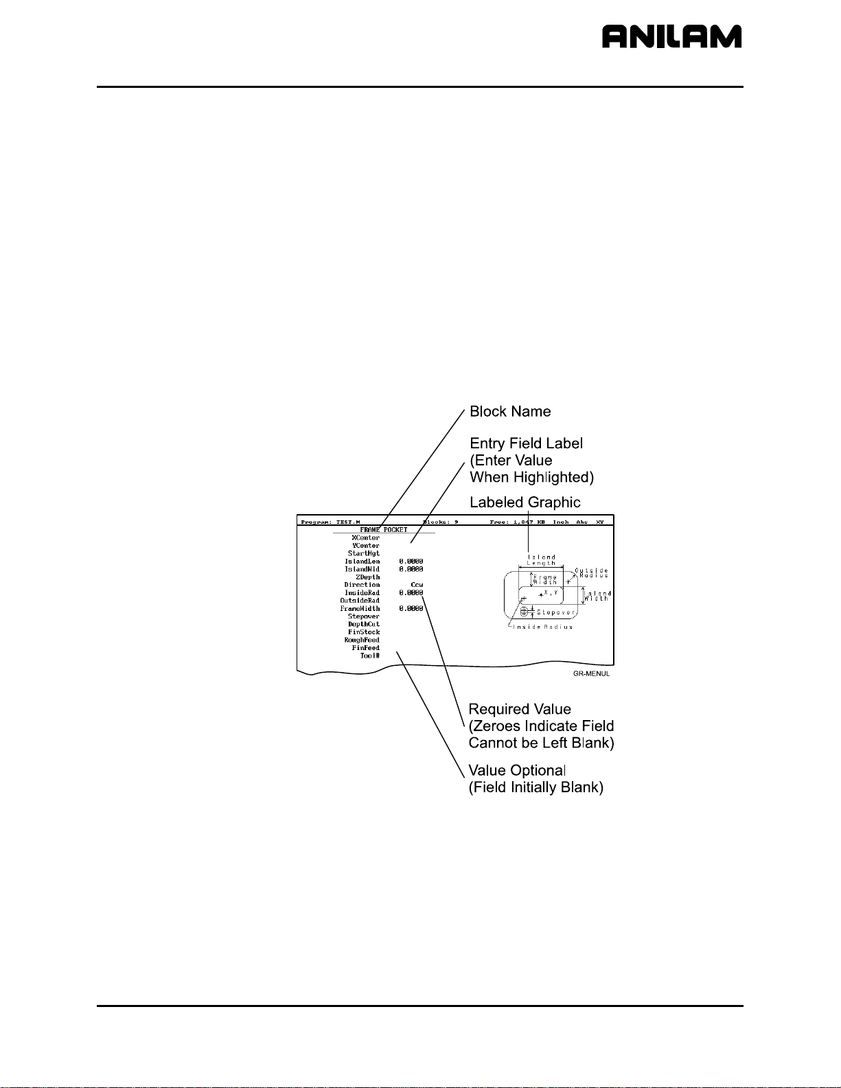
CNC Programming and Operations Manual
P/N 70000504I - Writing Programs
Writing Program Blocks
You can program a block for a move type, mode, or cycle using one of
the following: hot keys, soft keys, or pop-up menus.
To program a block, activate its graphic menu and fill in the appropriate
values. To save a program block, press Save (F10) or press
the last entry field in the graphic menu. The CNC adds the new block to
the Program Listing.
The <End Of Program> block is the last line of a program. The CNC
automatically numbers new blocks and inserts them in front of the
<End Of Program> block.
Using Graphic Menus
The Program Editor displays full screen graphic menus to write and edit
program blocks. Refer to Figure 4-1.
ENTER on
Figure 4-1, Sample Graphic Menu
Graphic menus activate with the first entry field highlighted. To enter
values, highlight the appropriate entry field, and press
ENTER to advance
the highlight to the next entry field. With the last entry field highlighted,
press
ENTER to close the menu and add the block to the program.
Press Save (F10) from any entry field to close the graphic menu and add
the block to the program. Move the highlight from field to field using the
ARROW keys. Fill out entry fields in any order.
All rights reserved. Subject to change without notice. 4-3
November 2009
Page 58

CNC Programming and Operations Manual
P/N 70000504I - Writing Programs
Press CLEAR to remove values in the highlighted field.
There are two types of entry fields in a graphic menu:
Optional entry fields Blank when the graphic menu activates.
Required entry fields Contain 0.000 when the graphic menu
activates.
Required entry fields contain a 0.0000 default value. Change the value
as required. Optional entry fields do not require a value. When left blank,
the CNC usually assumes a default value or position. If the optional field
is a position, the value defaults to the current position. If the optional field
is a mode or tool change, the current mode and tool remain active. If the
optional field is an angle, the value defaults to 0.0 degrees.
Type decimal points and negative signs where needed. Otherwise, the
CNC assumes a positive whole number.
Press +/- to insert a negative sign or toggle selections in some entry fields
(for example, Cw/Ccw fields).
No Move Blocks
Programming an Absolute/Incremental Mode Change
Programming an Inch/MM Mode Change
No Move Blocks does not initiate machine moves. Use No Move Blocks
to set modes (Incremental/Absolute, etc.), activate tools (Tool#), and set
feedrates (Feed).
A Dim (dimension) block sets the Absolute (Abs.) or Incremental (Incr.)
Mode.
To program a Dim block:
1. In Edit Mode, press
ABS/INC. The SET ABS/INCR DIMENSION
graphic menu prompts you to select Abs or Incr.
2. Press +/- to toggle the mode.
3. Press Save (F10) or
ENTER to add the block to the Program Listing.
A Unit block sets the Inch (Inch) or Millimeter (MM) Mode.
To program a Unit block:
1. In Edit Mode, press
7/UNIT. The SET INCH/MM UNIT graphic menu
prompts you to select Inch/MM.
2. Press +/- to toggle the selection.
3. Press Save (F10) or
4-4 All rights reserved. Subject to change without notice.
November 2009
ENTER to add block to the Program Listing.
Page 59

CNC Programming and Operations Manual
P/N 70000504I - Writing Programs
Programming a Tool Change
Identify tools with tool numbers. When you activate a tool, its tool length
and diameter offsets activate. List these values on the corresponding row
of the Tool Page. Refer to “Section 10 - Tool Management” for
information on the Tool Page.
NOTE: The CNC also activates listed coolant (optional) and spindle
operations (optional).
Tool-length offset remains in effect until a different tool activates. Always
turn off tool-diameter compensation and ramp off before activating a new
tool.
NOTE: You can program tool numbers with most moves; they do not
require a separate block. Each time a tool activates, the CNC
holds the program to permit installation of the new tool.
Programming unnecessary tool changes slows down production.
Activate Tool #0 to set the tool-length offset and diameter to 0.0.
To change a tool:
NOTE: An absolute move to Tool #0, Z0 fully retracts the quill. An
incremental command to Z0 maintains the current position.
1. In Absolute Mode, program a Rapid Z0, Tool #0 to cancel length
offsets and retract the quill to a safe position.
2. Program a Rapid move to the tool change XY position (usually
Machine Zero).
3. Program a block to activate the required tool (example: Tool#1).
When the CNC encounters the Tool# command, it holds optional
spindle and coolant functions. The operator can now change the tool.
4. Press
START to resume operation. The CNC activates applicable tool
compensation, spindle, and coolant activities.
NOTE: Program tool changes in separate blocks to make them easier to
find.
Activating a Tool
To activate a tool:
1. In Edit Mode, press
5/TOOL. The TOOL MOUNT graphic menu
prompts for Tool #.
2. Type tool number and press
ENTER to add the Tool# block to the
Program Listing.
All rights reserved. Subject to change without notice. 4-5
November 2009
Page 60

CNC Programming and Operations Manual
P/N 70000504I - Writing Programs
Activating Tool-Diameter Compensation
Refer to “Section 1 - CNC Programming Concepts” for basic information
on tool-diameter compensation. You can compensate most move types.
Compensation is modal and remains active until you cancel or change it.
Turn compensation on or off in (Rapid or Line) ramp moves. Ramp
moves offset the tool on the programmed path by half the tool diameter.
Tool compensation affects all subsequent moves until canceled.
The ToolComp command, available in Line or Rapid graphic menus, sets
the required tool compensation. Settings include:
• Left (of the path)
• Right (of the path)
• Off (cancel compensation)
When the field is left blank, the current compensation, if any, remains in
effect.
Many canned cycles include automatic tool compensation. Activate the
correct tool diameter to ensure accuracy in these cycles. The required
tool activates within the cycle.
Refer to Table 4-1 for a list of move and cycle compensation
requirements.
Table 4-1, Move and Cycle Compensation Requirements
Move or Cycle Program a Rapid or Line
move to activate tool
comp before you program
the move or cycle. Tool
diameter must be active.
Rapid
Line
Modal
Arc
Ellipse
X --X --X --X --X ---
(Has special
requirements. Refer to
“Section 5 - Programming
Canned Cycles, Ellipses,
and Spirals” for more
information.)
Spiral
--- ---
(No compensation
available.)
Activate/deactivate
compensation
automatically when you
program the move or cycle.
Tool diameter must be
active.
(Continued…)
4-6 All rights reserved. Subject to change without notice.
November 2009
Page 61

CNC Programming and Operations Manual
P/N 70000504I - Writing Programs
Table 4-1, Move and Cycle Compensation Requirements (Continued)
Move or Cycle Program a Rapid or Line
move to activate tool
comp before you program
the move or cycle. Tool
diameter must be active.
Face
--- X
(Affects only step-over.)
Rectangular Profile
--- X
Cycle
Circular Profile Cycle
Rectangular Pocket
--- X
--- X
Cycle
Circular Pocket Cycle
Frame Pocket Cycle
Irregular Pocket Cycle
Mold Rotation Cycle
--- X
--- X
--- X
--- X
(Has special
requirements. Refer to
“Section 5” for more
information.)
Activate/deactivate
compensation
automatically when you
program the move or cycle.
Tool diameter must be
active.
Elbow Mold Cycle
(No compensation
available.)
Programming a Dwell
--- ---
Dwell pauses a running program for a specified length of time, in
seconds. Dwell resolution is 0.1 sec. When the operator types 0.0
seconds (infinite dwell), the CNC will hold indefinitely. Press
START to
restart the CNC after an infinite dwell.
To program a Dwell using hot keys:
1. In Edit Mode, press
8/DWELL. The DWELL graphic menu prompts for
length of time in seconds.
2. Type the time, and press
ENTER to add Dwell block to the Program
Listing.
To program a Dwell using soft keys:
1. In Edit Mode, press Sub (F8) to display the Secondary soft key
functions.
2. Press Dwell (F7) to activate the DWELL graphic menu.
3. Type the time, and press
ENTER to add Dwell block to the Program
Listing.
All rights reserved. Subject to change without notice. 4-7
November 2009
Page 62

CNC Programming and Operations Manual
P/N 70000504I - Writing Programs
Programming a Return to Machine Zero
NOTE: The CNC measures all typed coordinates in the Machine Home
graphic menu from Machine Zero. The CNC homes axes one at
a time, in the order indicated in the Setup Utility.
A Home block re-establishes a permanent reference position located on
the machine. The position is called Machine Zero. Program a Home
block using one of the two methods described in Table 4-2.
Table 4-2, Homing Methods
Homing Method Required Action
1. Indicate axes
Activate Machine Home graphic menu. Press
required X, Y, Z-axis keys. On each axis
selected, machine feeds from the current
position to the limit switch, reverses direction
and travels to the first detected zero crossing,
and sets Machine Zero at that point.
2. Type coordinates
Activate Machine Home graphic menu. For
each required axis, highlight the axis entry field
and type a coordinate (example: X0, Y-1, Z-4).
The machine rapids to the typed coordinate,
then feeds to the limit switch, reverses direction
and travels to the first detected zero crossing,
and sets Machine Zero at that point.
Use Homing Method 1 to execute a homing sequence in feed. Use
Homing Method 2 to execute a homing sequence that rapids to the typed
coordinate, then initiates the homing sequence.
To activate the Machine Home graphic menu:
1. In the Edit Mode, press Mill (F5) to display the Mill soft keys.
2. Press More (F7) to display the More pop-up menu.
3. Highlight Home and press
ENTER to display the Machine Home
graphic menu.
The method used to set Machine Zero depends on which options the
builder installs. Check with the machine builder for detailed information.
4-8 All rights reserved. Subject to change without notice.
November 2009
Page 63

CNC Programming and Operations Manual
P/N 70000504I - Writing Programs
Programming Fixture Offsets
NOTE: Presets and SetZero will work with Fixture Offsets.
Refer to Figure 4-2.
Figure 4-2, Fixture Offset Graphic Menu
To program a Fixture Offset:
1. In Edit Mode, press Mill (F5) to display the Mill soft keys.
2. Press More (F7) to display the More pop-up menu.
3. Select Offsets and press
ENTER to display the Fixture Offset graphic
menu.
4. Fill in the labeled entry fields, as follows:
Fixture#
The Fixture-Offset number. Indicates which set of
values from the Fixture Offsets Table will be activated or
changed. Type a number 1 through 9, corresponding to
the Fixture Offsets Table, to activate or change an
offset. Type 0 to cancel fixture offsets.
X
X-offset coordinate. If you do not type a value, the CNC
activates the offsets listed in the Fixture Offsets Table
for the typed Fixture#. If you do type a value, the CNC
applies the typed offset. When the program runs, the
CNC updates the Fixture Offsets Table with the
specified X offset and clears the previous value.
Optional.
Y
Y-offset coordinate. If you do not type a value, the CNC
activates the offsets listed in the Fixture Offsets Table
for the typed Fixture#. If you do type a value, the CNC
applies the typed offset. When the program runs, the
CNC updates the Fixture Offsets Table with the
specified Y offset and clears the previous value.
Optional.
All rights reserved. Subject to change without notice. 4-9
November 2009
Page 64

CNC Programming and Operations Manual
P/N 70000504I - Writing Programs
Z
Z-Offset coordinate. If you do not type a value, the CNC
activates the offsets listed in the Fixture Offsets Table
for the typed Fixture#. If you do type a value, the CNC
applies the typed offset. When the program runs, the
CNC updates the Fixture Offsets Table with the
specified Z offset and clears the previous value.
Optional.
To cancel Fixture Offsets:
1. In Edit Mode, press Mill (F5) to display the Mill soft keys.
2. Press More (F7) to display the More pop-up menu.
3. Select Offsets, and press
ENTER to display the Fixture Offset graphic
menu.
4. Select Fixture#. In the highlighted entry field, type 0 to cancel Fixture
Offsets. (Do not fill in the other entry fields.)
Fixture Offsets Table
The Fixture Offsets Table, accessed using the Tool Page, contains the
typed values for Fixture Offsets 1 through 9. Refer to Figure 4-3.
NOTE: Handwheel and Jog features are available while the Fixture
Offsets Table is active.
Figure 4-3, Fixture Offsets Table
Activating the Fixture Offsets Table
To activate the Fixture Offsets Table:
1. In the Tool Page, press OFFSETS (F1).
4-10 All rights reserved. Subject to change without notice.
November 2009
Page 65

CNC Programming and Operations Manual
P/N 70000504I - Writing Programs
Changing Fixture Offsets in the Table
There are three ways to change the values in the table: manually type a
value, or calibrate the fixture offset table entry to the machine’s current
location (shown on the axis display), or adjust an existing entry.
To change a fixture offset to a manually typed coordinate:
1. Highlight a Fixture Offset (row 1 through 9).
2. Press an axis key (X, Y, or Z).
3. Type a value, and press
To calibrate the fixture offset table entry to the machine’s current location:
1. Highlight a Fixture Offset (row 1 through 9).
2. Press CalibX (F5), CalibY (F6), or CalibZ (F7) to store the current
machine position for the selected axis in the table.
To adjust a fixture offset table entry:
1. Highlight a Fixture Offset (row 1 through 9).
2. Press the ABS/INC key, or ALT + E on a keyboard, to display a pop-
up message, “Enter axis and adjustment value.”
3. Type the axis to adjust (X, Y, or Z) and the amount of the adjustment.
The adjustment value can be positive or negative.
4. Press
ENTER to adjust the value, and display the adjusted value in the
table.
Resetting Absolute Zero (Part Zero)
Absolute Zero is the X0, Y0 position for absolute dimensions. Refer to
“Section 1 - CNC Programming Concepts” for information on Absolute
Positioning. A SetZero block sets the Absolute Zero Reference of one or
more axes to a new position. Use SetZero in one of two ways: to reset
X0 Y0 or to preset the current location to typed coordinates.
ENTER to store the value in the table.
In axis presetting, non-zero XY values set the current machine position to
the typed coordinates. In axis resetting, X0 and Y0 values set the current
machine position as the new Absolute Zero Reference.
When the CNC executes the block, the X and Y values (zero or non-zero)
in the graphic menu redefine Absolute Zero.
In Figure 4-4, Executing a SetZero Block, diagram A shows Part Zero
and tool position prior to a SetZero block. In this example, the operator
programs a SetZero block with the following coordinates: X2, Y-1.
Diagram B shows Part Zero and tool position following the SetZero block.
The coordinates at the tool position become X2, Y-1. This, in effect,
moves Part Zero, as indicated.
All rights reserved. Subject to change without notice. 4-11
November 2009
Page 66

CNC Programming and Operations Manual
P/N 70000504I - Writing Programs
Figure 4-4, Executing a SetZero Block
Change Absolute Zero to cut more than one part with the same moves.
Restore the location of the original X0, Y0 reference at the end of the
program so that programmed part change positions do not move each
time the program runs. Refer to Figure 4-5.
Figure 4-5, Using SetZero in a Program
4-12 All rights reserved. Subject to change without notice.
November 2009
Page 67

CNC Programming and Operations Manual
P/N 70000504I - Writing Programs
When an axis entry field (X, Y, or Z) remains blank in a graphic menu, the
CNC does not change the position of that axis. Refer to Figure 4-6.
NOTE: In most programs, the Z-axis position does not change.
Changing the Z-axis position changes the Tool #0, Z0 position,
which alters all existing tool-length offsets.
Figure 4-6, Set Zero Graphic Menu
To program a SetZero block:
1. In Edit Mode, press Mill (F5) to change the Soft Key labels.
2. Press More (F7) to display the pop-up menu.
3. Position the highlight to select SetZero, and then press
Set Program Zero Graphic menu prompts for the absolute
coordinates of the machine’s current position.
4. Type the appropriate X, Y, and Z coordinates and press
the block to the Program Listing.
Programming a Plane Change
The CNC executes Arc moves and compensates for tool diameters in
three different planes (XY, YZ, and XZ). By default, the CNC operates in
the XY plane. Program a Plane block to change the CNC’s active plane.
Following moves in the XZ or YZ plane, program a second Plane block to
return to the XY plane. Refer to “Section 1 - CNC Programming
Concepts” for basic information on planes.
A Plane block also changes the active plane of the Program Editor. The
Program Editor customizes Arc graphic menus for the active plane.
When a plane block is deleted from the Program Listing, the active plane
of the Editor does not change.
ENTER. The
ENTER to add
To program a Plane block using hot keys (the keypad):
1. In Edit Mode, press
9/PLANE. The SET PLANE graphic menu prompts
for plane selection.
2. Press the +/- key to change the selection to the desired plane. Press
ENTER to add the block to the Program Listing.
All rights reserved. Subject to change without notice. 4-13
November 2009
Page 68

CNC Programming and Operations Manual
P/N 70000504I - Writing Programs
To program a Plane block using soft keys:
1. In Edit Mode press Mill (F5) to display the Mill soft keys.
2. Press More (F7) to display the More pop-up menu.
3. Highlight Plane, and press
prompts for plane selection.
4. Press +/- to change to the desired plane. Press
block to the Program Listing.
Programming a Feedrate Change
A Feed block sets the feedrate for Line moves, arcs, and cycles that do
not contain specifically programmed feedrates. Feed blocks also set the
feedrate for modal moves. Add Feed blocks whenever necessary.
NOTE: A Feed block does not activate the Feed Mode.
To program a Feed block from the hot keys (the keypad):
1. In Edit Mode, press
2. Type the required feedrate, and press
Program Listing.
To program a Feed block from the soft keys:
1. In Edit Mode, press Mill (F5) to display the Mill soft keys.
2. Press More (F7) to display the More pop-up menu.
3. Highlight Feed, and press
menu.
ENTER. The SET PLANE graphic menu
ENTER to add the
4/FEED to display the FEEDRATE graphic menu.
ENTER to add the block to the
ENTER to activate the FEEDRATE graphic
4. Press Save (F10) or
ENTER to add Feed block to the Program Listing.
If the machine has a 4th axis (typically, U) a feedrate can be programmed
for the U-axis using the FeedU block. If the U-axis is a rotary axis, the
units for the FeedU block are degrees per minute (deg/min); otherwise,
the units are the same as in the Feed block.
To program a FeedU block from the soft keys:
1. In Edit, or MDI, press Mill (F5) to display the Mill keys.
2. Press More (F7) to display the More keys
3. Highlight FeedU and press
4. Type the desired value, and press Save (F10) or
ENTER to display the FeedU graphic menu.
ENTER to add the
FeedU block to the program.
4-14 All rights reserved. Subject to change without notice.
November 2009
Page 69

CNC Programming and Operations Manual
P/N 70000504I - Writing Programs
Programming a Spindle RPM
If your CNC has a programmable spindle RPM, you can set the RPM in
one of the following ways.
• Each tool has an associated RPM entry in the tool page. When a tool
is made active, its associated RPM is used.
• You can use the RPM block in the program. This is especially
necessary when you use more than one spindle speed with a specific
tool.
To program an RPM block from the hot keys (the keypad):
1. In Edit Mode, press the
.
(Decimal/RPM) key to display the Spindle
RPM graphic menu.
2. Type the required spindle RPM and press
ENTER to add the block to
the Program Listing.
To program an RPM block from the soft keys:
1. In Edit Mode, press Mill (F5) to display the Mill soft keys.
2. Press More (F7) to display the More pop-up menu.
3. Highlight RPM and press
ENTER to activate the Spindle RPM graphic
menu.
4. Type the required RPM, and press Save (F10) or
ENTER to add RPM
block to the Program Listing.
All rights reserved. Subject to change without notice. 4-15
November 2009
Page 70

CNC Programming and Operations Manual
P/N 70000504I - Writing Programs
Straight Moves
Programming a Rapid Move
Rapid moves run at the CNC’s Rapid rate and save time when positioning
for a cut or a canned cycle.
Use Rapid moves to activate/deactivate tool diameter compensation and
cutter compensation. Refer to Figure 4-7.
Figure 4-7, Rapid Move Graphic Menu
To program a Rapid move using hot keys (the keypad):
1. In Edit Mode, press
1/RAPID to activate the RAPID (XY) graphic menu.
2. Type the X, Y, and Z coordinates in the appropriate entry fields.
3. Press +/- to set ToolComp (optional) and press
ENTER to highlight
Tool#.
4. Type a tool number (optional), and press
ENTER to add the Rapid
block to the Program Listing.
To program a Rapid move using soft keys:
1. In Edit Mode, press Mill (F5) to display the Mill soft keys.
2. Press Rapid (F2) to activate the RAPID (XY) graphic menu.
3. Type the appropriate values and settings in the labeled entry fields.
4-16 All rights reserved. Subject to change without notice.
November 2009
Page 71

CNC Programming and Operations Manual
P/N 70000504I - Writing Programs
Programming a Line Move
Straight line moves run in Feed. Refer to Figure 4-8.
Figure 4-8, Line Move Graphic Menu
To program a Line move using hot keys (the keypad):
1. In Edit Mode, press
2. Type the appropriate values and settings in the labeled entry fields.
To program a Line move using soft keys:
1. In Edit Mode, press Mill (F5) to change the Soft Key labels.
2. Press Line (F3) to display the LINE (XY) graphic menu.
3. Type the appropriate values and settings in the labeled entry fields.
4. With the last entry field highlighted, press
the Program Listing.
Programming a Modal Move
A modal move is a straight move executed in the active Rapid or Feed
Mode.
To program a Modal move:
1. In Edit Mode, press X, Y, or Z. The MODAL MOVE graphic menu
prompts for the X, Y, and Z positions.
2. Type the required positions.
3. From the last field on the graphic menu, press
add the modal move block (Xn Yn Zn) to the program.
2/LINE to activate the LINE (XY) graphic menu.
ENTER to add the block to
ENTER or Save (F10) to
NOTE: When using modal moves, be sure the CNC is in the required
Rapid or Line Mode. The CNC executes Line Mode moves in
Feed Mode.
All rights reserved. Subject to change without notice. 4-17
November 2009
Page 72

CNC Programming and Operations Manual
P/N 70000504I - Writing Programs
Teach Mode (Programming from the Part)
In Teach Mode, the CNC writes program blocks that duplicate manually
executed moves. Teach Mode allows you to select endpoints from a part
diagram to program a move without knowing the coordinates.
Teach Mode also operates in DRO Mode.
To activate the Teach Mode from the Edit screen:
1. Press Teach (F1). The Teach (F1) soft key highlights.
Use Teach Mode to program a Line, Rapid, or Modal move. Refer to
Figure 4-9.
Figure 4-9, Teach Mode Screen
To program a Teach move:
1. In Edit Mode, press Teach (F1) to activate Teach Mode. The display
shows the current location.
2. Manually position the machine at the endpoint.
3. Press Rapid (F2), Line (F3), or Modal (F4) to indicate the required
move type. The CNC inserts the appropriate block into the listing.
4. Program all required moves in Teach Mode.
5. Press Teach (F1) to deactivate Teach Mode.
4-18 All rights reserved. Subject to change without notice.
November 2009
Page 73
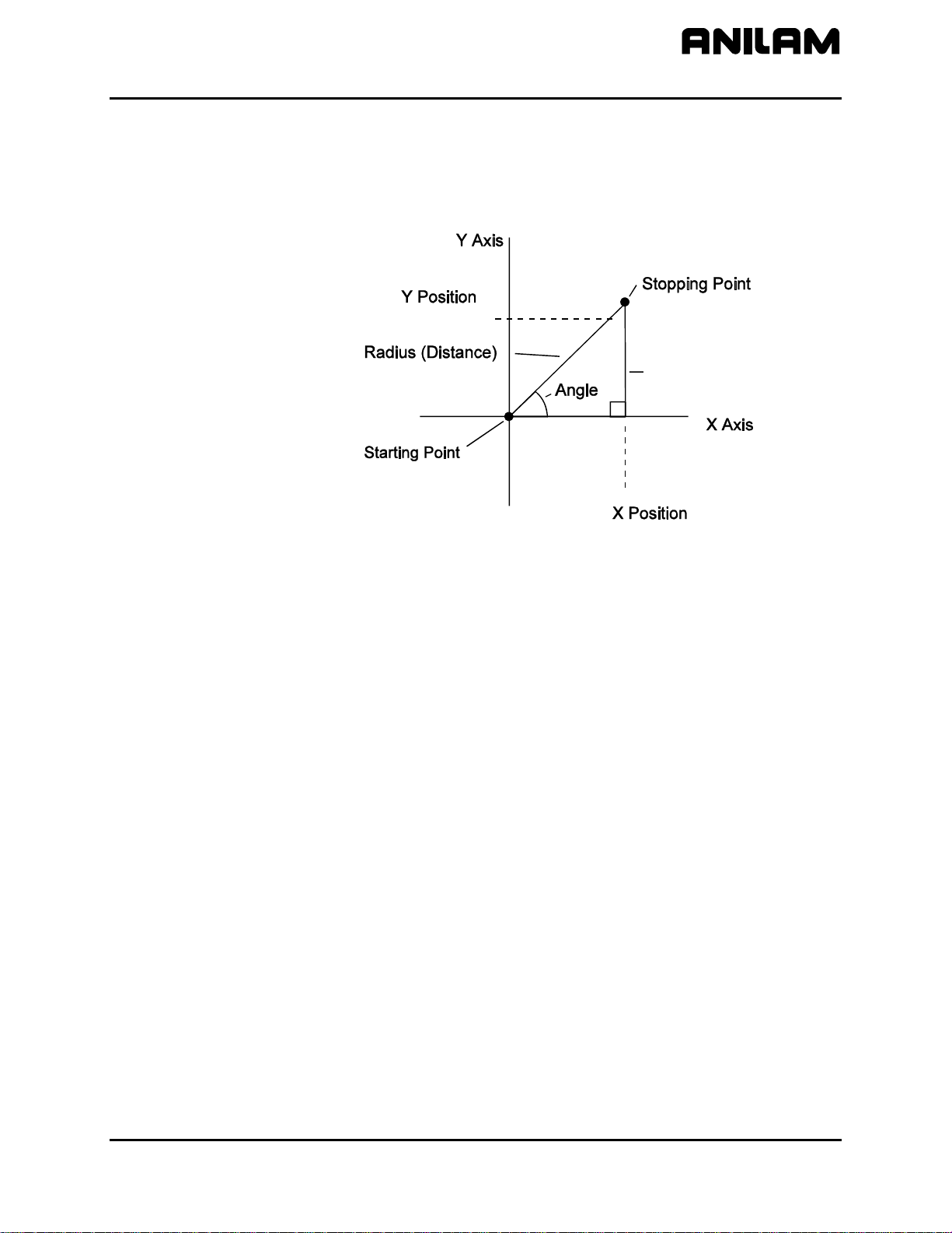
CNC Programming and Operations Manual
P/N 70000504I - Writing Programs
Line or Rapid Moves
Using the X, Y, or XY endpoints, the CNC can write Line or Rapid moves.
The CNC calculates the missing endpoint(s). Define the move as part of
a right triangle with the components identified as in Figure 4-10.
NOSTOP
Figure 4-10, Move Orientation
The CNC can calculate move endpoints, given:
• Angle and radius
• X position and angle
• Y position and angle
• X position and radius
• Y position and radius
The Rapid and Line graphic menus are similar. However, the Rapid
graphic menus do not contain CornerRad or Feed entry fields. Use
either the Absolute or Incremental Mode.
All rights reserved. Subject to change without notice. 4-19
November 2009
Page 74

CNC Programming and Operations Manual
P/N 70000504I - Writing Programs
Programming a Move Using XY Location, Radii, or Angles
To program a move using a Line or Rapid block:
1. In Edit Mode, press Mill (F5) and select either Rapid (F2) or Line
(F3).
– or –
In Edit Mode, press
1/RAPID or 2/LINE to display the RAPID (XY) or
LINE (XY) graphic menu.
2. Press More. . . (F4) to display the Template pop-up menu. Refer to
Figure 4-11.
Figure 4-11, Rapid/Line Template Pop-up Menu
3. Highlight the appropriate template, and press
ENTER to display the
graphic menu.
4. Type the required values/settings in the entry fields.
4-20 All rights reserved. Subject to change without notice.
November 2009
Page 75

CNC Programming and Operations Manual
r
r
g
r
(Neg
)
g
r
(
)
P/N 70000504I - Writing Programs
Arcs
Selecting the Plane for an Arc
Refer to “Section 1 - CNC Programming Concepts” for information on
planes and Arc directions. The CNC executes Arcs in the XY plane by
default. For an Arc in the XZ or YZ plane, program the plane change
before the Arc move. The plane change customizes the Arc graphic
menus for the required plane.
The graphic menus for moves in the XY, XZ, and YZ planes contain the
same entry fields. Entry fields for selected plane positions require a
value.
After a move in the XZ or YZ plane, return the CNC to the XY plane.
NOTE: To activate a new plane in the Program Editor, program a plane
change block.
Program Arc moves:
Using the endpoint and radius
Using the center and endpoint
Using the center and angle
Programming an Arc Using an Endpoint and Radius
To define the Endpoint - Radius Arc, type the direction of the Arc, the
endpoint, and the radius. The CNC cuts an Arc of the specified radius
from the current position to the endpoint. You must correctly define the
modal endpoint coordinates in the Absolute or Incremental Mode.
In the XY plane, if the Z-axis starting and end points differ, the arc is a
helix.
Two Arcs can intersect any two points: an Arc with an included angle
less than 180 degrees and an Arc with an included angle greater than
180 degrees. Refer to Figure 4-12.
IncludedAngle
Less Than 180 De
Positive Radius V alue
t
Sta
Point
ees
End
Point
Start
Point
IncludedAngle
eaterThan 180 De
G
ative Radius Value
ees
End
Point
Figure 4-12, Endpoint Radius Arc Types
All rights reserved. Subject to change without notice. 4-21
November 2009
Page 76

CNC Programming and Operations Manual
P/N 70000504I - Writing Programs
To program an Arc with an included angle less than 180 degrees, type a
positive radius value. To program an Arc with an included angle greater
than 180 degrees, type a negative radius value. The CNC selects which
Arc center to use, based on the sign of the typed value.
To program an Arc using an endpoint and radius, using hot keys (the
keypad):
1. In Edit Mode, press
3/ARC. The ARC (END POINT - RADIUS) graphic
menu prompts for labeled values.
2. Fill in the entry fields as labeled.
To program an Arc using an endpoint and radius, using soft keys:
1. In Edit Mode, press Mill (F5) to display the Mill secondary soft keys.
2. Press Arc (F4) to display the ARC (END POINT - RADIUS) graphic
menu. Refer to Figure 4-13.
Figure 4-13, ARC (END POINT - RADIUS) Graphic Menu
3. Fill in the ARC (END POINT - RADIUS) entry fields:
Direction Specifies a clockwise (Cw) or counterclockwise
(Ccw) direction. Press +/- to toggle the setting.
Selection required.
X The X coordinate of the Arc endpoint. Value
required.
Y The Y coordinate of the Arc endpoint. Value
required.
Z The Z coordinate of the endpoint. Optional.
Radius The radius of the Arc. Value required (positive or
negative).
CornerRad Corner radius setting. Optional. (Refer to
“Section 1 - CNC Programming Concepts” for
details.)
Feed Feedrate. Optional.
Tool# Active tool. Optional.
4-22 All rights reserved. Subject to change without notice.
November 2009
Page 77

CNC Programming and Operations Manual
P/N 70000504I - Writing Programs
Programming an Arc Using the Center and Endpoint
NOTE: Use Center and Endpoint Arcs to cut helical threads.
To define the Center - Endpoint Arc, type the endpoint, arc center, and
direction. The CNC cuts an Arc from the current position to the end point.
In Absolute Mode, the CNC measures the Arc center and endpoint from
Absolute Zero. In Incremental Mode, the CNC measures the Arc center
and end point from the starting position of the arc.
NOTE: Ensure that the required Absolute or Incremental Mode is active.
When the Z-axis start and end points differ in the XY plane, the Arc is a
helix. The Revs value determines the number of rotations used to
machine the helix.
The CNC calculates the radius from the specified starting point and Arc
center. Therefore, the endpoint must lie along the Arc’s path. If the
endpoint does not lie along the Arc’s path, the CNC will adjust the center
or end point. Configure whether the CNC will adjust the center or
endpoint in the Setup Utility. Endpoint is preferred. The machine builder
sets the maximum arc circle center adjustment in the Setup Utility. If the
error exceeds the setup tolerance, the CNC generates an error message.
To program a Center - End Point Arc using hot keys (the keypad):
1. In Edit Mode, press 3/
ARC to display the ARC (CENTER – END
POINT) graphic menu. Refer to Figure 4-14.
Figure 4-14, ARC (CENTER – END POINT) Graphic Menu
2. Press More... (F4) to display the Arc template pop-up menu. Refer to
Figure 4-15, Arc Template Pop-Up Menu.
3. Highlight the Center – End Point template and press
the
ARC (CENTER – END POINT) graphic menu.
ENTER to display
4. Type the required values or settings in the entry fields.
All rights reserved. Subject to change without notice. 4-23
November 2009
Page 78

CNC Programming and Operations Manual
P/N 70000504I - Writing Programs
To program a Center – End Point Arc using soft keys:
1. In Edit Mode, press Mill (F5) to display the
Mill secondary soft keys.
2. Press Arc (F4) to display the ARC (END POINT - RADIUS) graphic
menu.
3. Press More... (F4) to display the Arc Template pop-up menu. (Refer
to Figure 4-15).
Figure 4-15, Arc Template Pop-Up Menu
4. Highlight the Center – End Point template and press
ENTER. The
ARC (CENTER – END POINT) graphic menu prompts for the labeled
values.
5. Type the required values or setting in the following labeled entry
fields:
Direction Allows you to select a clockwise (Cw) or
counterclockwise (Ccw) direction. Press +/- to toggle
the setting. Selection required.
X The X coordinate of the Arc end point. Optional.
Y The Y coordinate of the Arc end point. Optional.
Z The Z coordinate of the Arc end point. Optional.
XCenter The X coordinate of the Arc center. Value required.
YCenter The Y coordinate of the Arc center. Value required.
Revs Number of revolutions from start position to endpoint.
Optional.
CornerRad Corner radius setting. Optional. (Refer “Section 1 -
CNC Programming Concepts” for details.)
Feed Feedrate. Optional.
Tool# Active tool. Optional.
4-24 All rights reserved. Subject to change without notice.
November 2009
Page 79

CNC Programming and Operations Manual
(Pr
)
(
A
)
A
r
A
(Pr
)
(
)
P/N 70000504I - Writing Programs
Programming an Arc Using the Center and the Included Angle
To define the Center - Angle Arc, type the arc center and the included
angle. The CNC cuts the Arc from the present position until the Arc
travels the specified number of degrees. The CNC calculates the radius,
which is the distance between the start position and the center point.
Specify the appropriate Absolute or Incremental Mode for the angle and
center point. Refer to Figure 4-16 and Figure 4-17.
The direction (Cw/Ccw) of the Arc and the sign (+/-) of the angle control
the path of the tool.
If the Z-axis starting and end points differ, the Arc will be a helix.
°
90
bsolute Position
60
°
Cw Tool Path
Ccw Tool Path
CenterPoint
bsolute Position
Figure 4-16, Absolute Mode, Center - Angle Arc
°
Incremental Position
60
CenterPoint
Incremental Position
°
Incremental Position
60
°
0
bsoluteAngle
Refe
StartingPoint
esent Position
Ccw Tool Path
StartingPoint
esent Position
Cw Tool Path
ence
Figure 4-17, Incremental Mode, Center - Angle Arc
All rights reserved. Subject to change without notice. 4-25
November 2009
Page 80

CNC Programming and Operations Manual
P/N 70000504I - Writing Programs
Refer to Figure 4-18.
Figure 4-18, Arc (Center - Angle) Graphic Menu
To program an Arc using the center and the included angle using hot
keys (the keypad):
1. In Edit Mode, press
3/ARC to display the ARC (ENDPOINT - RADIUS)
graphic menu.
2. Press More... (F4) to display the Arc Template pop-up menu. (Refer
to Figure 4-15, Arc Template Pop-Up Menu.)
3. Highlight the Center - Angle template and press
ENTER to display the
ARC (CENTER - ANGLE) graphic menu.
4. Type the required values and settings in the entry fields.
To program an Arc using the center and the included angle using soft
keys:
1. In Edit Mode, press Mill (F5) to activate the Mill secondary soft keys.
2. Press Arc (F4) to display the ARC (END POINT - RADIUS) graphic
menu.
3. Press More... (F4) to display the Arc template pop-up menu. Refer to
Figure 4-15, Arc Template Pop-Up Menu.
4. Highlight the Center - Angle template and press
ENTER to display the
ARC (CENTER - ANGLE) graphic menu.
5. Fill in the ARC (CENTER - ANGLE) entry fields:
Direction Specifies a clockwise (Cw) or counterclockwise (Ccw)
direction. Press +/- to toggle the setting. Selection
required.
XCenter The X coordinate of the Arc’s center. Value required.
YCenter The Y coordinate of the Arc’s center. Value required.
Angle Included angle of the Arc. Value required.
Z The Z coordinate of the Arc endpoint. Optional.
CornerRad Corner radius setting. Optional. (Refer to “Section 1 -
CNC Programming Concepts” for details.)
Feed Feedrate. Optional.
Tool# Active tool. Optional.
4-26 All rights reserved. Subject to change without notice.
November 2009
Page 81

CNC Programming and Operations Manual
P/N 70000504I - Writing Programs
Programming M-Code Blocks
The CNC supports M-Code functions. Enable available M-Codes at
installation. Refer to the machine builder’s technical data to determine
which M-Codes are available.
Some programmed events initiate the same functions activated using
M-Codes. Refer to Table 4-3 for a list of the most commonly used
M-Code functions.
Table 4-3, M-Code Functions
M-Code
Programmed Event
M02 EndMain block.
M03
Activation of a tool that lists a
FWD spindle direction on the
Tool Page.
M04
Activation of a tool that lists a
REV spindle direction on the
Tool Page.
M05
Activation of a tool block (to
allow a tool change).
Activation of a tool that
contains a Tool Page spindle
direction OFF.
M03, M05, M04
M08
Execution of Tapping Cycle.
Activation of a tool with coolant
ON listed on the Tool Page.
Standard Function Usage
(ref. EIA Standard RS 274-D)
Stops spindle and coolant.
Start CW spindle rotation.
Start CCW spindle rotation.
Stop spindle in normal manner.
Start CW spindle rotation, stop
spindle then start CCW spindle
rotation.
Turn coolant pump ON.
M09
Activation of a tool with coolant
Turn coolant pump OFF.
OFF listed on the Tool Page.
To program an MCode block:
1. In Edit Mode, press MCode (F8). The Graphic menu prompts for the
MCode number and X, Y, Z values.
2. Type the values and press Save (F10) or
ENTER to add MCode block
to the program.
All rights reserved. Subject to change without notice. 4-27
November 2009
Page 82
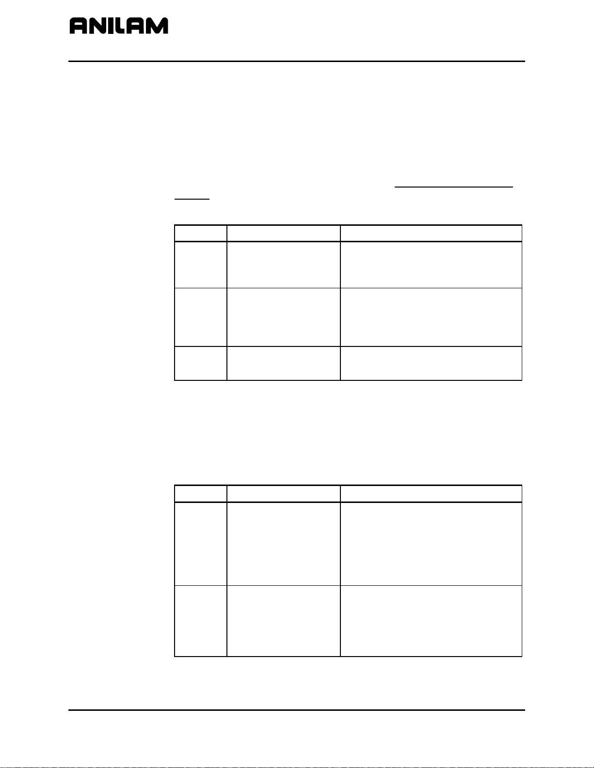
CNC Programming and Operations Manual
P/N 70000504I - Writing Programs
Dry Run M-Codes
In Dry Run Mode, the machine axes (X, Y, and Z) move through the
program without cutting into the work. The CNC disables coolant
operation and the work may or may not be placed on the table.
Activate Dry Run Mode with M-Codes 105 and 106. Deactivate it with
M107. Refer to Table 4-4. Dry Run feedrates are set in the Setup Utility.
They are often set at greater speeds than conventional feedrates. You
can set them at any desired rate. Refer to the 3000M CNC Setup Utility
Manual, P/N 70000499, for details.
Table 4-4, Dry Run Mode M-Codes
M-Code Function Description
M105 Dry Run Mode ON,
M106 Dry Run Mode ON,
M107
U-Axis Synchronization M-Codes
For systems that have a U-axis, the U-axis can be synchronized with XYZ
or unsynchronized. The following M-codes are used to specify U-axis
synchronization in Manual Data Input (MDI) or in a program. The builder
sets the default configuration. Refer to Table 4-5.
Table 4-5, U-Axis Synchronization M-Codes
M-Code Function Description
M900
all axes
no Z-axis
Cancel Dry Run
Mode
Activate 4
th
(U) axis
synchronization
Enables machine Z Dry Run Mode.
Program runs at dry run feedrates
specified in the Setup Utility.
Enables machine Dry Run Mode.
Program runs at dry run feedrates
specified in the Setup Utility, without
moving the Z-axis.
Cancels active Dry Run Mode.
Axes to be synchronized must also
be programmed.
Example: Mcode 9000 U will
synchronize the U-axis with XYZ
feedrate. All moves feedrates will
be vectored.
M901
Deactivate 4
axis synchronization
th
(U)
Indicate axis to deactivate
synchronization.
Example: Mcode 9001 U will
unsynchronize the U-axis with XYZ
feedrate.
4-28 All rights reserved. Subject to change without notice.
November 2009
Page 83

CNC Programming and Operations Manual
P/N 70000504I - Programming Canned Cycles, Ellipses, and Spirals
Section 5 - Programming Canned Cycles, Ellipses, and Spirals
Drilling Cycles
Drill cycles simplify the programming required for repetitive drilling,
boring, and tapping operations. Select specific drill cycles from the
Program Editor’s Drill (F3) pop-up menu:
NOTE: Program all blocks by filling in the entry fields of a Graphic Menu.
Basic (drill cycle)
Pecking
Boring
Chip Break
Tapping
Drilling Off
Pattern
Bolt Hole
Thread Mill
ZMode
Drill cycles are modal. When the CNC encounters a block for any type of
Drill cycle, it executes that cycle at the endpoint of each subsequent
move until it encounters a DrillOff block. To change drill cycle
parameters between moves, program a new drill block.
Program a ZMode block to switch the operation between two-axes and
three-axes as needed in a program. To program a ZMode block, select
ZMode from the Drill (F3) pop-up menu and then press +/- key to select:
TwoAxAuto, TwoAxStep, or ThreeAxes.
If the CNC is in ThreeAxes mode and a TwoAxStep or TwoAxAuto
block is ran, the operator is prompted to disengage the Z-axis and,
subsequently, to position the Z-axis manually when needed. When in
TwoAxStep block, the machine will stop on every move, as when drilling.
When in a TwoAxAuto block, as when milling a contour, the motion is
continuous until the CNC sees a ZMove.
If the CNC is in TwoAxAuto or TwoAxStep mode and a ThreeAxes
block is ran, the operator is prompted to re-engage the Z-axis. To
re-engage the Z-axis drive system, lift the quill handle until you feel the
drive assembly become seated, then tighten the quick release knob.
Once the Z-axis is re-engaged, the operator can jog the Z-axis to the
homing mark on the front of the Z-axis drive system and (if needed) press
START to perform a Homing sequence or Manual (F4) to cancel the
Homing sequence. Another press of the
START key allows the program to
continue to run normally.
All rights reserved. Subject to change without notice. 5-1
November 2009
Page 84

CNC Programming and Operations Manual
P/N 70000504I - Programming Canned Cycles, Ellipses, and Spirals
Basic Drill Cycle
The Basic Drill Cycle is a modal operation. When the CNC receives a
BasicDrill command, it performs the drilling operation at the endpoint of
every subsequent block until it receives a Drilling Off block. To change
Basic Drilling dimensions cancel the current cycle and program a new
cycle.
During the cycle, the tool rapids to the StartHgt, then Z feeds to ZDepth.
To provide clearance for the next move, at the end of the cycle, the tool
rapids to ReturnHgt.
Z-axis depth can be changed by placing a new Z depth on the same line
as the X- and/or Y-axis location of the hole you want the new depth
applied. A Z address on a line of its own will cause the control to drill the
new depth at the current location.
Program a DrillOff block to deactivate the cycle. You can program any
number of patterns and moves before turning off the cycle.
To program a BasicDrill block:
1. In Edit mode, press Drill (F3) to display the Drill cycle pop-up menu.
2. Highlight Basic, and press
ENTER to display the BASIC DRILLING
Graphic Menu. Refer to Figure 5-1.
Figure 5-1, BASIC DRILLING Graphic Menu
3. Enter the required values and settings in the entry fields. With the last
entry field highlighted, press
ENTER. The display clears and the CNC
adds the BasicDrill block to the program listing.
4. Program subsequent moves to position the tool at the required drilling
location(s). The CNC will drill a hole at the endpoint of every move.
5. After programming the last drill move, press Drill (F3) to display the
Drill cycle pop-up menu.
5-2 All rights reserved. Subject to change without notice.
November 2009
6. Highlight Drilling Off, and press
ENTER to cancel the Drilling Mode.
Page 85
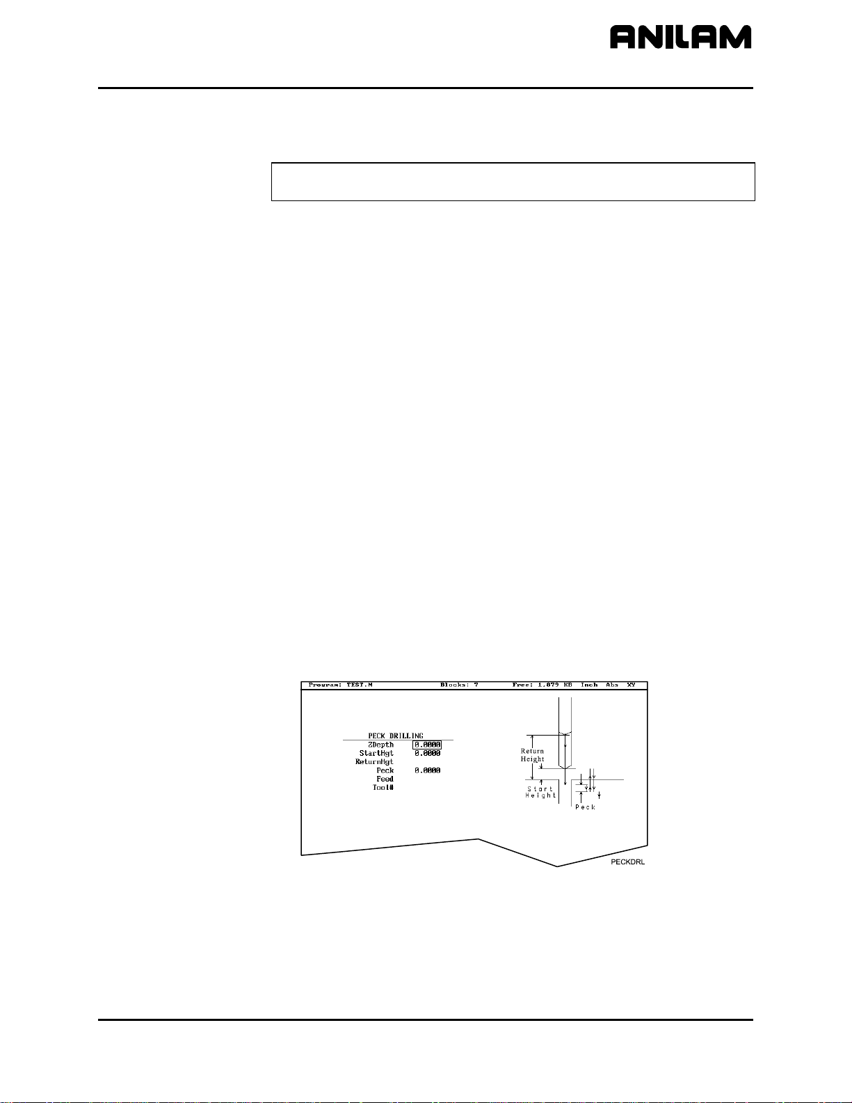
CNC Programming and Operations Manual
P/N 70000504I - Programming Canned Cycles, Ellipses, and Spirals
BASIC DRILLING entry fields:
ZDepth The absolute depth of the finished hole. (Required)
NOTE: ZDepth must be lower than StartHgt. StartHgt is 0.100
inches (2.0 mm) above the work surface.
StartHgt The absolute Z position the CNC rapids to before
feeding into the work. (Required)
ReturnHgt The absolute position to which the tool returns at
the end of the cycle. (Optional)
Feed Feedrate. (Optional)
Tool# Active tool. (Optional)
Peck Drilling Cycle
Peck drilling is a modal operation. When the CNC receives a PeckDrill
command, it peck-drills at the endpoint of every subsequent block until it
receives a Drilling Off block. To change Peck Drilling dimensions,
cancel the current PeckDrill cycle and program a new cycle.
The cycle starts when the CNC is in position. The tool rapids to the Z
start height (StartHgt); feeds to the Peck depth; then rapids back to the
StartHgt. This cycle repeats until the tool reaches ZDepth. At the end of
the cycle, the tool rapids to the ReturnHgt to provide clearance for the
next move.
To program a Peck Drilling cycle:
1. In Edit mode, press Drill (F3) to display the Drill cycle pop-up menu.
2. Highlight Pecking, and press
ENTER to display the PECK DRILLING
Graphic Menu. Refer to Figure 5-2.
Figure 5-2, PECK DRILLING Graphic Menu
3. Enter the required values and settings in the entry fields. With the last
entry field highlighted, press
ENTER. The Display clears and the CNC
adds the PeckDrill block to the program listing.
4. Program subsequent moves to position the tool at the required drilling
location(s). The CNC will drill a hole at the endpoint of every move.
All rights reserved. Subject to change without notice. 5-3
November 2009
Page 86

CNC Programming and Operations Manual
P/N 70000504I - Programming Canned Cycles, Ellipses, and Spirals
5. After programming the last drill move, press Drill (F3) to display the
Drill cycle pop-up menu.
Boring Cycle
6. Highlight Drilling Off, and press
ENTER to cancel the Drilling Mode.
PECK DRILLING entry fields:
ZDepth Absolute depth of the finished hole. (Required)
NOTE: ZDepth must be lower than StartHgt. StartHgt is 0.100
inches (2.0 mm) above the work surface.
StartHgt Absolute Z position the CNC rapids to before
feeding into work. (Required)
ReturnHgt Absolute position the tool returns to at the end of
the cycle. (Optional)
Peck Depth drilled in each peck. (Required)
Tool# Active tool. (Optional)
Boring is a modal operation. When the CNC encounters a Boring block,
it executes a Boring Cycle at the endpoint of every subsequent move until
it sees a Drilling Off block. To change Boring Cycle dimensions between
moves, deactivate the cycle and program a new boring block.
The cycle starts when the CNC is in position. The tool rapids to the
StartHgt, feeds to ZDepth, and then feeds back to StartHgt. At the end
of the cycle, the tool moves to ReturnHgt to provide clearance for the
next move.
When running a Dwell block, the CNC pauses at ZDepth for the indicated
time period (in seconds). Dwell resolution is 0.1 sec. When you enter
0.0 sec., the CNC dwells until manually restarted.
To program a Boring cycle:
1. In Edit mode, press Drill (F3) to display the Drill cycle pop-up menu.
2. Highlight Boring, and press
ENTER to display the BORING CYCLE
Graphic Menu. Refer to Figure 5-3.
Figure 5-3, BORING CYCLE Graphic Menu
5-4 All rights reserved. Subject to change without notice.
November 2009
Page 87

CNC Programming and Operations Manual
P/N 70000504I - Programming Canned Cycles, Ellipses, and Spirals
BORING CYCLE entry fields:
ZDepth Absolute depth of the finished hole. (Required)
NOTE: ZDepth must be lower than StartHgt. StartHgt is 0.100
inches (2.0 MM) above the work surface.
StartHgt Absolute Z position the CNC rapids to before
feeding into work. (Required)
ReturnHgt Absolute position to which the tool returns at the
end of the cycle. (Optional)
Dwell Length of time for pause at ZDepth. (Optional)
Feed Feedrate. (Optional)
Tool# Active tool. (Optional)
3. Enter the required values and settings in the entry fields. With the last
entry field highlighted, press
ENTER. The display clears and the CNC
adds Boring block to the program listing.
4. Program subsequent moves to position the work at the required
boring locations. The CNC executes the Boring Cycle at the endpoint
of every move.
5. After programming the last boring position, press Drill (F3) to display
6. Highlight Drilling Off, and press
Chip Break Cycle
The Chip Break Cycle is modal. Once the CNC encounters a ChipBreak
block, it executes the Chip Break Cycle at the endpoint of each block until
it sees a Drilling Off block. To change Chip Break values between
moves, deactivate the cycle and program a new one.
The cycle starts when the CNC is in position. The tool rapids to the
StartHgt, feeds to the FirstPeck, retracts 0.02 inches [0.4 mm (default
value)], then feeds to the next peck. Retract moves occur at the end of
each peck in order to break the chip. This cycle repeats until the tool
reaches ZDepth. At the end of the cycle, the tool moves to ReturnHgt to
provide clearance for the next move.
Enter a PeckDecr value to decrement the depth of each peck by the
specified amount. The MinPeck sets the minimum peck the cycle can
decrement. A ChipBrkInc is the size of the retract move that breaks the
chip.
Peck to the RetractDep, retract to the StartHgt, and then peck to the
next RetractDep increment. The first full retract occurs one RetractDep
increment after the first peck.
the Drill cycle pop-up menu.
ENTER to cancel the cycle.
All rights reserved. Subject to change without notice. 5-5
November 2009
Page 88
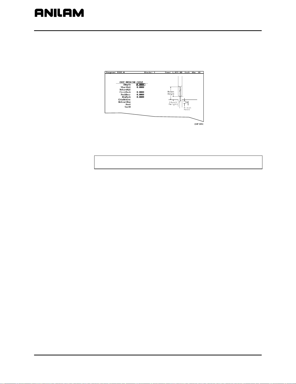
CNC Programming and Operations Manual
P/N 70000504I - Programming Canned Cycles, Ellipses, and Spirals
To program a Chip Break cycle:
1. In Edit Mode, press Drill (F3) to display the Drill cycle pop-up menu.
2. Highlight Chip Break, and press
ENTER to display the CHIP
BREAKING CYCLE Graphic Menu. Refer to Figure 5-4.
Figure 5-4, CHIP BREAKING CYCLE Graphic Menu
CHIP BREAKING CYCLE entry fields:
ZDepth Absolute depth of the finished hole. (Required)
NOTE: ZDepth must be lower than StartHgt. StartHgt is 0.100
inches (2.0 mm) above the work surface.
StartHgt Absolute Z position to which the CNC rapids before
feeding into work. (Required)
ReturnHgt Absolute position to which the tool returns at the
end of the cycle. (Optional)
FirstPeck Absolute depth drilled in each peck. (Required)
PeckDecr Amount to subtract from previous peck (positive
dimension). (Required)
MinPeck Smallest peck allowed. (Required)
ChipBrkInc Size of chip break retract. (Optional)
RetractDep Z increment before full retract. (Optional)
Tool# Active tool. (Optional)
3. Enter the required values and settings in the entry fields.
entry field highlighted, press
ENTER. The display clears and the CNC
With the last
adds the Chip Break block to the program listing.
4. Program the drilling location(s). The CNC will drill a hole at the
endpoint of every move until it receives the Drilling Off command.
5. Program the Drilling Off command. After programming the last drill
move, press Drill (F3) to display the Drill cycle pop-up menu.
6. Highlight Drilling Off, and press
ENTER to add the DrillOff block to
the program Listing.
5-6 All rights reserved. Subject to change without notice.
November 2009
Page 89

CNC Programming and Operations Manual
P/N 70000504I - Programming Canned Cycles, Ellipses, and Spirals
Tapping Cycle
The Tapping Cycle is available only on machines equipped with spindle
RPM control and M-Codes (M3, M4, and M5).
In order for the cycle to operate, you must enter Spindle RPM value for
the active tool on the Tool Page. During execution, the CNC uses the
Spindle RPM value from the Tool Page and the programmed threads per
inch (or pitch) value from the block to calculate the proper feedrate for
tapping.
When the cycle, runs the CNC rapids to the StartHgt and feeds to the
ZDepth. The spindle stops and reverses direction to retract the tool from
the hole. At ReturnHgt, the spindle stops and changes back to the
original direction in preparation for the next programmed move.
Use the Tapping Cycle with any available pattern. A Drilling Off block
cancels the cycle.
NOTE: The system supports spindle FWD, REV, OFF (M3, M4, M5),
and spindle RPM control. At machine setup the machine builder
determines which M-Codes to install.
To program a Tapping block:
1. In Edit mode, press Drill (F3) to display the Drill cycle pop-up menu.
2. Highlight Tapping, and press
ENTER to display the TAPPING CYCLE
Graphic Menu. Refer to Figure 5-5.
Figure 5-5, Tapping Cycle Graphic Menu
TAPPING CYCLE entry fields:
ZDepth Absolute depth of the tapped threads. (Required)
NOTE: ZDepth must be lower than StartHgt. StartHgt is 0.100
inches (2.0 mm) above the work surface.
StartHgt Absolute Z position to which the CNC rapids before
feeding into work. (Required)
ReturnHgt Absolute position to which the tool returns at the
end of the cycle. (Optional)
All rights reserved. Subject to change without notice. 5-7
November 2009
Page 90

CNC Programming and Operations Manual
P/N 70000504I - Programming Canned Cycles, Ellipses, and Spirals
TPIorLead TPI in Inch or Lead in millimeters. (Required)
Tool# Active tool. (Optional)
Dwell Length of time for pause at top of hole and at
ZDepth. (Optional)
3. Enter the required settings and values in the entry fields. With the last
entry field highlighted, press
ENTER to clear the display and add the
new tapping cycle block to the program listing.
4. Program subsequent moves to position the location of the tapped
holes. The CNC will tap a hole at the endpoint of every move until it
receives a Drilling Off command.
5. To program a Drilling Off block, press Drill (F3) to display the Drill
cycle pop-up menu.
Drill Pattern
6. Highlight Drilling Off, and press
ENTER to display the Drill Off block
in the program listing.
The Pattern Cycle instructs the CNC to execute a pattern of regularly
spaced moves. Locate a Pattern Cycle between a Drill Cycle and a
DrillOff block. The CNC executes the Drill Cycle at every endpoint in the
pattern.
In a Pattern Cycle, enter a size, location, spacing, Tool #, and rotation
angle of the pattern.
To program a Drill Pattern cycle:
1. In Edit Mode, press Drill (F3) to display the Drill cycle pop-up menu.
2. Select Pattern from the Drill pop-up menu, and press
ENTER to
display the PATTERN DRILL Graphic Menu. Refer to Figure 5-6.
Figure 5-6, Pattern Drill Graphic Menu
PATTERN DRILL entry fields:
X X coordinate of corner hole. If no entry made, CNC
puts corner hole at present location. (Optional)
Y Y coordinate of corner hole. If no entry made, CNC
puts corner hole at present location. (Optional)
5-8 All rights reserved. Subject to change without notice.
November 2009
Page 91

CNC Programming and Operations Manual
P/N 70000504I - Programming Canned Cycles, Ellipses, and Spirals
#XHoles Number of rows that lie along the X-axis. Must enter
value greater than 0. (Required)
#YHoles Number of rows that lie along the Y-axis. Must enter
value greater than 0. (Required)
NOTE: Enter 1 in either the #XHoles or the #YHoles field to drill a
single row or column.
Xincr X-axis increment (spacing) of holes. (Required)
Yincr Y-axis increment (spacing) of holes. (Required)
Angle This value rotates the pattern. The XY corner hole is
the pivot, and the rotation angle is the number of
degrees counterclockwise from the X-axis or 3 o’clock
position.
NOTE: Use a Drilling Off block to cancel cycle.
3. Enter the required values and settings in the entry fields.
Bolt Hole Pattern
The Bolt Hole Cycle instructs the CNC to run a series of moves with
endpoints that form a circular pattern. At each of these endpoints, you
can run a previously programmed Drill Cycle.
You should first program a Drill Cycle to describe the hole being drilled.
Then follow the Drill Cycle by one or more moves, patterns, or Bolt Hole
cycles to position the CNC for the Drill Cycle. A DrillOff block cancels
the cycle.
To program a Bolt Hole Cycle:
1. In Edit Mode, press Drill (F3) to display a pop-up menu.
2. Select Bolt Hole from the pop-up menu, and press
ENTER to display
the BOLTHOLE DRILL Graphic Menu. Refer to Figure 5-7.
Figure 5-7, BOLTHOLE DRILL Graphic Menu
All rights reserved. Subject to change without notice. 5-9
November 2009
Page 92

CNC Programming and Operations Manual
P/N 70000504I - Programming Canned Cycles, Ellipses, and Spirals
3. Enter the following required values and settings in the BOLTHOLE
DRILL entry fields:
XCenter Absolute X center of the bolt hole pattern. If no
entry is made, the CNC puts the center of the Bolt
Hole pattern at X0. (Required)
YCenter Absolute Y center of the bolt hole pattern. If no
entry is made, the CNC puts the center of the Bolt
Hole pattern at Y0. (Required)
NOTE: Use absolute center point coordinates whenever possible.
#Holes Number of equally spaced holes in the circular
pattern. (Required)
Diameter Diameter of the circular pattern. (Required)
StartAngle The number of degrees (from the 3 o’clock
position) to the first hole. (Required)
EndAngle The number of degrees (from the 3 o’clock
position) to the last hole. (Optional)
IndexAngle The number of degrees that the 3 o’clock reference
position rotates around the center (rotates entire
pattern). (Optional)
NOTE: Use a Drilling Off block to cancel the cycle.
5-10 All rights reserved. Subject to change without notice.
November 2009
Page 93

CNC Programming and Operations Manual
P/N 70000504I - Programming Canned Cycles, Ellipses, and Spirals
Thread Milling Cycle
WARNING: The first move in this cycle is a rapid move to the center of
the thread before moving the Z-axis. Make sure the tool is properly
located before calling up this cycle.
Thread Milling Cycle simplifies the programming required to mill a thread.
Use the thread milling for cutting inside or outside threads. It will cut
either Inch or MM, left or right hand, and Z movement up or down. A
single tooth or multi-toothed tool may be used. Start can be at the top or
bottom of the hole or boss. Tool Length Offset is set the same as with
any other tool or operation. A tool diameter also has to be set in the tool
table, as cutter compensation is built into this cycle (cutter compensation
is not allowed during the use of this cycle). The tool must be positioned
at center of hole or boss, or the parameters for XCenter and YCenter
must be specified in the cycle.
XCenter, YCenter, ArcInRad, StockAmt, Passes, RoughFeed,
FinFeed, and TaperAng are all optional Input; all other parameters must
be programmed. If the feed rates are not programmed, the CNC will use
last feed rate used.
In a tapered thread the Major Diameter is always the major diameter of
thread where the ZStart is set. Inside diameter is at finished depth and
outside diameter is the diameter of boss.
To program a Thread Milling Cycle:
1. In Edit Mode, press Drill (F3) to display a pop-up menu.
2. Select Thread Mill from the pop-up menu, and press
ENTER to display
the Thread Mill Graphic Menu. Refer to Figure 5-8.
Figure 5-8, Thread Mill Graphic Menu
All rights reserved. Subject to change without notice. 5-11
November 2009
Page 94

CNC Programming and Operations Manual
P/N 70000504I - Programming Canned Cycles, Ellipses, and Spirals
3. Enter the following required values and settings in the Thread Mill
entry fields:
XCenter Absolute X coordinate of the center of the thread.
If no coordinate is entered, the CNC puts the center
of thread as the current tool position. (Optional)
YCenter Absolute Y coordinate of the center of the thread.
If no coordinate is entered, the CNC puts the center
of the thread as the current tool position. (Optional)
ZFinish Absolute Z position where the thread cut will finish.
This can be above or below the start position
depending on the direction of the thread cut, up or
down. (Required)
ZStart Absolute Z position where the thread cut starts.
This can be above or below the finish position
depending on the direction of the thread cut, up or
down. If not set, the cycle will use the current Z
tool position. (Optional)
ZSafePosn An Absolute safe Z position above the part for rapid
moves in X and/or Y. (Required)
WARNING: ZSafePosn must be above the part to
avoid a crash while positioning.
MajorDia Major thread diameter. For a tapered thread, it will
be the major diameter at the Z start position. If you
have a tapered hole and you start at the top and
cut down, you would have a different major
diameter than if you started at the bottom and cut
up. (Required)
+
–
Value cuts in the CW direction
Value cuts in the CCW direction
ThdDepth Depth of thread. The incremental depth of thread
on one side: (Required)
+
–
Value is inside thread
Value is outside thread
TPIorLead Threads per inch (TPI) or lead of thread.
(Required)
NOTE: The minimum number of threads per inch
is “1”
5-12 All rights reserved. Subject to change without notice.
November 2009
Page 95

CNC Programming and Operations Manual
P/N 70000504I - Programming Canned Cycles, Ellipses, and Spirals
ArcInRad Size of radius arcing into start of thread. (Optional)
NOTE: If ArcInRad is a positive value or not set and the thread is “inside,” the cycle will
always return to the center between passes.
If ArcInRad is a negative value, the cutter will move to the start or end point that
is closest to the center if inside thread, and farthest away from center if outside
thread.
If ArcInRad is not specified and the thread is “outside,” the cutter will back away
from the largest diameter by an amount equal to the thread depth.
StockAmt Amount to leave for a finish pass after the roughing
passes. (Optional)
Passes Number of roughing cuts to be taken. (Optional)
NOTE: If StockAmt is not set or set to zero and Passes is 1 or 0, the cycle will make
just one pass at the full depth..
If StockAmt is set to greater than zero and Passes is 1 or 0, the cycle will make
just one pass at the stock depth and one pass at full thread depth.
If Passes is set to a negative number, all non-cutting positioning moves will be
rapid.
RoughFeed Feedrate for roughing. (If not set, the cycle will use
the current active feedrate.) (Optional)
FinFeed Feedrate for the finish pass. (If not set, the cycle
will use the current active feedrate.) (Optional)
TaperAng Angle on one side of the thread (not the included
angle). The angle is measured from the right side
going counter clockwise with a positive number and
clockwise with a negative number. A straight pipe
tape with an inside cut would be -1.7833. If not set,
then the thread is straight. (Optional)
If X and Y are not programmed, position tool center of the thread before
calling the “Thread Mill” cycle:
• X and Y will rapid to the starting position of the thread.
• Z will rapid to the safe height specified in ZSafePosn.
• The Z axis will feed down to the start cut position ZStart. This could
be above or below the Z position specified in the ZFinish position.
• Depending on what is in the ArcInRad parameter, the tool will arc into
the first cut position.
All rights reserved. Subject to change without notice. 5-13
November 2009
Page 96

CNC Programming and Operations Manual
P/N 70000504I - Programming Canned Cycles, Ellipses, and Spirals
• Spiral up or down, depending on the difference between ZFinish and
ZStart and go counterclockwise or clockwise depending if MajorDia
is plus or minus.
• Then arc-out and feed to the thread center for inside threads, or a
safe distance away from the thread for outside threads depending on
the value in ArcInRad.
• Then feed back to the ZStart height.
• Then feed X and Y to the next depth of cut. The depth of each
roughing pass will be the thread depth specified in the ThdDepth
parameter minus the stock amount specified in the StockAmt
parameter, divided by the number of roughing passes specified in the
Passes parameter.
• The cycle repeats this process until the final finish pass.
• It will then cut the thread at the full thread major diameter.
When cutting a tapered on an inside thread, care should be taken. An
error will be generated if the diameter on the small end of the taper
becomes too small for the tool to fit along with arc in and out moves. Not
entering an arc-in value in the ArcInRad parameter will allow the cycle to
move to the center of the hole for maximum clearance.
5-14 All rights reserved. Subject to change without notice.
November 2009
Page 97

CNC Programming and Operations Manual
P/N 70000504I - Programming Canned Cycles, Ellipses, and Spirals
Sample Thread Program
This program will cut an 8 TPI thread starting at 0.1 above the hole. The
major diameter of the thread is 1 inch. It will take 2 roughing cuts and 1
finish cut with a 0.625 cutter.
Dim Abs
Tool# 1
Rapid X 1.0000 Y 1.0000
Rapid Z 0.1000
ThreadMill Finish -1.0 ZStart 0.1 ZSafePosn .5 MajorDia 1.0
ThdDepth .0625 TPIorLead 8 ArcInRad 0.1
StockAmt 0.002 Passes 2 RoughFeed 20.0
FinFeed 5.0
Rapid Z 5.0000
EndMain
The tool will spiral down the thread pitch of 8 threads per inch, finishing at
a depth of –1. The starting height is 0.1, the safe rapid Z height is 0.5,
the major thread diameter is 1 inch, and depth of thread is 0.0625. The
arc-in radius is 0.1 and the stock amount for the finish pass is 0.002. The
rough feedrate is 20.0 and the finish feedrate is 5.0.
NOTE: If you would like all non-cutting positioning moves to be rapid,
set Passes to a negative number. The idea is to initially set
Passes as a positive number and after proving out the program,
change it to a negative number for faster production. If you only
need one pass to size and you want the positioning moves to be
rapid, set Passes to -1.
All rights reserved. Subject to change without notice. 5-15
November 2009
Page 98

CNC Programming and Operations Manual
P/N 70000504I - Programming Canned Cycles, Ellipses, and Spirals
Pocket Cycles
NOTE: Program all blocks by filling in the entry fields of a Graphic Menu.
Pocket canned cycles simplify the programming of repetitive moves
required to mill out pockets. Select the pocket-canned cycles from the
Program Editor Pocket (F4) pop-up menu. Refer to Figure 5-9.
NOTE: Programming a Tool# in a pocket cycle automatically activates
the necessary tool compensation for that cycle.
Face
Rect. Profile
Circ. Profile
Rectangular
Circular
Frame
Hole
IRRegular
Mold Rotation
Elbow Milling
Islands
POCKETPU
Figure 5-9, Pocket Pop-up Menu
Select specific pocket cycles from the Program Editor’s Pocket (F4) pop-
up menu:
Facing Cycle
Rectangular Profile Cycle
Circular Profile Cycle
Rectangular Pocket Cycle
Circular Pocket Cycle
Frame Pocket Cycle
Hole – Mill Cycle
Irregular Pocket Cycle
Mold Rotation
Elbow Milling Cycle
Pockets with Islands
5-16 All rights reserved. Subject to change without notice.
November 2009
Page 99

CNC Programming and Operations Manual
P/N 70000504I - Programming Canned Cycles, Ellipses, and Spirals
Facing Cycle
Facing cycles simplify the programming required to face the surface of a
part.
Execution begins one tool radius from the start point. The selected stepover determines the approach axes.
NOTE: A ZDepth entry is not necessary if you program only one level
plus finish stock.
Facing cycles can start in any corner of the surface and cut in any
direction, depending on the sign (+/-) of the Length and Width values.
Program a slightly oversize Length and Width to ensure complete facing
of the surface.
At the end of the cycle, the tool rapids to StartHgt, then rapids back to
the start position. Refer to Figure 5-10.
Figure 5-10, Face Cycle Tool Approach
To program a Facing cycle:
1. In Edit Mode, press Pocket (F4) to display a pop-up menu.
2. Move the highlight to select Face, and press
ENTER to display the
FACE POCKET Graphic Menu. Refer to Figure 5-11.
Figure 5-11, FACE POCKET Graphic Menu
All rights reserved. Subject to change without notice. 5-17
November 2009
Page 100

CNC Programming and Operations Manual
P/N 70000504I - Programming Canned Cycles, Ellipses, and Spirals
NOTE: ZDepth must be lower than StartHgt. StartHgt is 0.100 inches
(2.0 mm) above the work surface.
FACE POCKET entry fields:
ZDepth Absolute depth of the finished surface. (Required)
StartHgt Absolute Z position the CNC rapids to before
feeding into work. (Required)
XStart X coordinate of the starting point. (Optional)
YStart Y coordinate of the starting point. (Optional)
NOTE: Enter the required absolute XStart and YStart coordinates
when possible.
Length X-axis length to be faced. (Required)
Width Y-axis length to be faced. (Required)
XStepover Width of cut in the X-axis direction. When no value
is entered, the CNC defaults to 70% of the active
tool radius. Maximum step-over permitted is 70%
of the active tool radius.
YStepover Width of cut in the Y-axis direction. When no value
is entered, the CNC defaults to 70% of the active
tool radius. Maximum step-over permitted is 70%
of the active tool radius.
NOTE: Enter either an X or Y step-over. Do not enter both.
NOTE: The Program Editor inadvertently will allow you to write a
block containing a Stepover value greater than 70% of the
active tool radius. To reveal this type of error, test the
program in the Draw Graphics Mode.
Tool# Active tool. (Optional)
3. Enter the required values and settings in the entry fields.
5-18 All rights reserved. Subject to change without notice.
November 2009
 Loading...