

Page 1
Linear
Slot Diffusers
Models SLAD/Free Flo/Pro Jet
Installation
Operation
and Maintenance
IOM–005
Effective 6/22/09
Rev C
Page 2

2
1220 Watson Center Road • Carson, CA 90745
Tel: (310) 835-7500 • Fax: (310) 835-0448
Contents
SLAD / Free Flo / Pro Jet Installation Instructions - Hemmed Duct Installation...............................................................................3
Free Flo / Pro Jet Installation Instructions - During Hard Ceiling Installation...................................................................................4
Expansion & Contraction of Linear Aluminum Diffusers...................................................................................................................6
SLAD - How to use Adjustment Tool ................................................................................................................................................7
Proper product installation is the responsibility of the installer, as dictated by industry standards, codes and/or specifications. Information is subject to
change without notice. Product line drawings are not to scale. Latest information is available at www.anemostat.com
Page 3
1220 Watson Center Road • Carson, CA 90745
Tel: (310) 835-7500 • Fax: (310) 835-0448
3
SLAD / Free Flo / Pro Jet Installation Instructions
A. HEMMED DUCT INSTALLATION
• Duct supports linear diffuser
• Drywall pre-installed
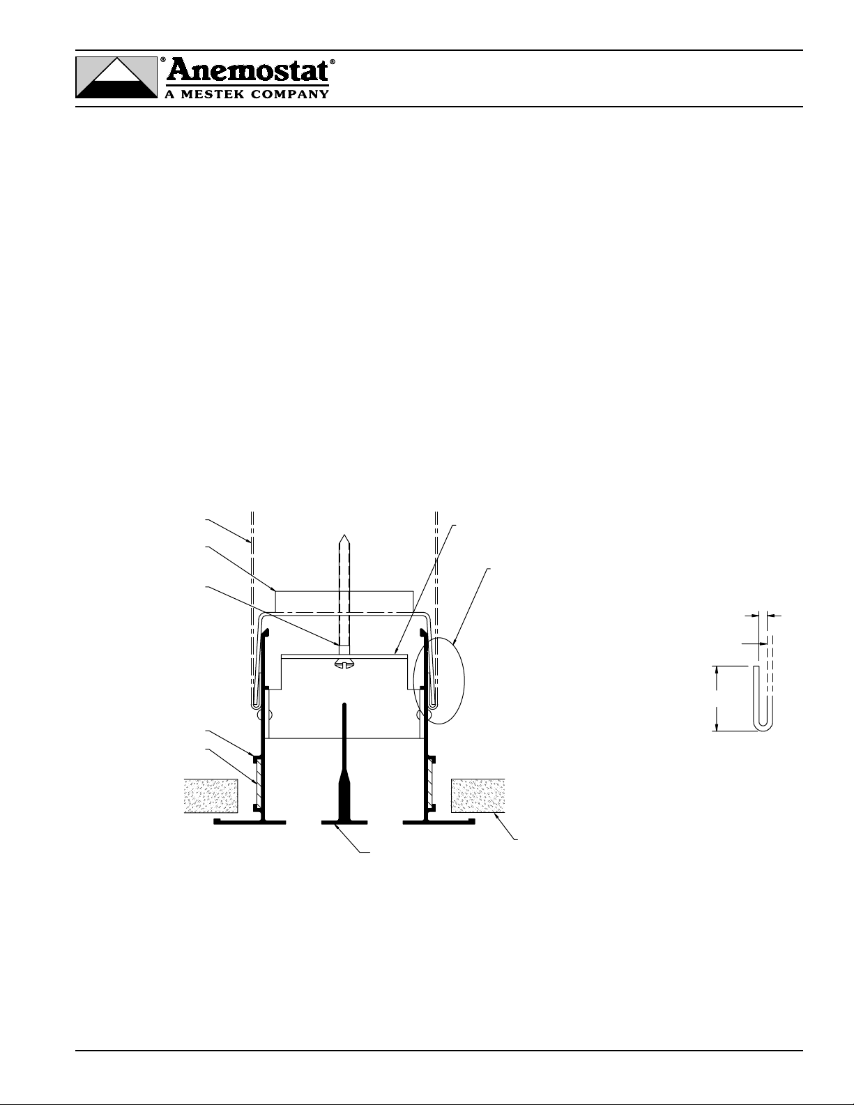
1. After plenum is securely fixed above the ceiling, position mounting brackets in the hem edge of the plenum so that they will line
up with the linear diffuser’s cross members (stays). The hem edge may be crimped into the hole of the mounting bracket with
pliers. This will retain the mounting bracket in position as the mounting screws are attached.
2. Before positioning the diffuser in the ceiling, remove the pattern control element/adjustment vane assembly from a
1-slot diffuser, or remove the inner vane(s) from a 2- or more-slot diffuser to expose the mounting holes in the diffuser cross
member (stay). Both the pattern control element/adjustment vane assembly and the inner vane(s) can be removed by pulling
them out of the friction clip from the face side of the diffuser. This is more easily done at the floor level.
3. Position the diffuser in the ceiling and push the No.8 x 1-3/4” screw through the diffuser cross member and screw into the
mounting bracket until the diffuser is pulled snug to the ceiling.
4. Re-attach the pattern control element/adjustment vanes assembly or vanes that were previously removed.
OUTER FRAME
ALIGNMENT STRIPS
No. 8 x 1-3/4" LONG
SHEET METAL SCREW
MOUNTING BRACKET
(FIELD INSTALLATION)
DUCT (BY OTHERS)
SEE HEM DETAIL
INNER VANE
(SNAP-IN)
CEILING
STAY
HEM DETAIL
Duct must be hemmed
as shown (On sides only)
3/8 TO 3/4
3/32
REF. DUCT
OPENING
Page 4

Free Flo / Pro Jet Installation Instructions
B. Ceiling Supported
• Installed prior to drywall installation
4
1220 Watson Center Road • Carson, CA 90745
Tel: (310) 835-7500 • Fax: (310) 835-0448
TAPE/JOINT COMPOUND
FOR FEATHERING FLUSH
TO FINISHED CEILING
DRYWALL
MOUNTING TAB
FOR 5/8" THICK
DRYWALL
FRAME
SERRATED DIFFUSER
OUTER FRAME FACE TO
PROVIDE BETTER ADHESIVE
SURFACE FOR JOINT COMPOUND
Models FFBF / PJBF Installation Detail
Outer Frame Detail
Outer Frame Detail
TAPE/JOINT COMPOUND
FOR FEATHERING FLUSH
TO FINISHED CEILING
DRYWALL
REVERSIBLE
MOUNTING TAB
FOR 5/8" OR 7/8"
THICK DRYWALL
FRAME
SERRATED DIFFUSER
OUTER FRAME FACE TO
PROVIDE BETTER ADHESIVE
SURFACE FOR JOINT COMPOUND
Models FFCM / PJCM Installation Detail
Diffuser Face Preparation Notes
• Diffuser face comes serrated for better adhesion of joint compound.
• Thoroughly remove any oil, dust, dirt, or residue from the entire diffuser face using a solvent or
degreaser.
• For increased adhesion, apply a bonding agent along the entire diffuser face. Be sure to allow
sufficient drying time before applying joint compound.
• Embed mesh or paper tape as standard practice across joints to prevent cracking.
Page 5

1220 Watson Center Road • Carson, CA 90745
Tel: (310) 835-7500 • Fax: (310) 835-0448
Free Flo / Pro Jet Installation Instructions
During Hard Ceiling Installation
5
BF/CM Frame Style Installation
• Slide mounting brackets into diffuser outer frame channels. Make sure brackets are appropriately
spaced to evenly distribute diffuser weight (approximately 20" - 24").
• Lift Free Flo/Pro Jet diffuser up to the framing members. Secure into place using mounting screws
appropriate for the framing material. Screws are field supplied.
• Position drywall between diffuser frame mounting brackets and flanged face of diffuser.
• Apply joint compound to face of diffuser and feather to drywall ceiling for a clean, finished look.
(See “Diffuser Face Preparation Notes”, page 4)
Continuous Runs
FRAMING MEMBER
FRAME MOUNTING
BRACKETS
DRYWALL
DRYWALL
MOUNTING
SCREW
FFBF/PJBF
DIFFUSER
FFCM/PJCM DIFFUSER
(NOTE: MOUNTING METHOD
IS SIMILAR TO FFBF/PJBF DIFFUSER)
STRIPS TO ALIGN
CONTINUOUS RUNS
Page 6
Expansion & Contraction (in inches) of
Linear Aluminum Diffusers
The expansion and contraction of aluminum linear diffusers, due to temperature differential, is shown below. In most normal
installations, the slight hairline crack that results when linear diffusers are butted together, will be sufficient to allow for normal
expansion.
6
1220 Watson Center Road • Carson, CA 90745
Tel: (310) 835-7500 • Fax: (310) 835-0448
GRILLE
LENGTH
(ft.)
5'
10'
20'
30'
40'
50'
60'
80'
100'
120'
140'
160'
180'
TEMPERATURE DIFFERENTIAL
5° 10° 15° 20° 30° 40° 50° 60° 70° 80° 90°
.004 .008 .012 .016 .024 .032.039 .048 .054 .062 .070
.008 .016 .024 .031 .048 .060 .078 .096 .110 .120 .160
.016 .031 .047 .062 .093 .130 .160 .190 .220 .250 .320
.024 .047 .070 .093 .140 .190 .230.280.330.380 .470
.031 .062 .093 .130 .190 .250 .310 .380 .440 .500 .630
.040 .080 .120 .160 .240 .310 .390 .470 .550 .620 .700
.047 .093 .140 .190 .280.380 .470 .560 .650 .750 .840
.060 .130 .190 .250 .380 .500 .620 .750 .870 1.000 1.120
.080 .160 .230.310 .470 .620 .780.930 1.090 1.250 1.400
.093 .190 .280.380 .560 .750 .940 1.120 1.310 1.490 1.680
.110 .220 .330 .440 .660 .880 1.090 1.310 1.530 1.750 1.970
.130 .250 .380 .500 .750 1.000 1.250 .150 1.750 2.000 2.250
.140 .280 .420 .560 .840 1.120 1.400 1.670 1.950 2.2302.520
200'
.160 .310 .470 .620 .930 1.250 1.560 1.870 2.170 2.500 2.810
Page 7
1220 Watson Center Road • Carson, CA 90745
Tel: (310) 835-7500 • Fax: (310) 835-0448
7
SLAD
How to use Adjustment Tool
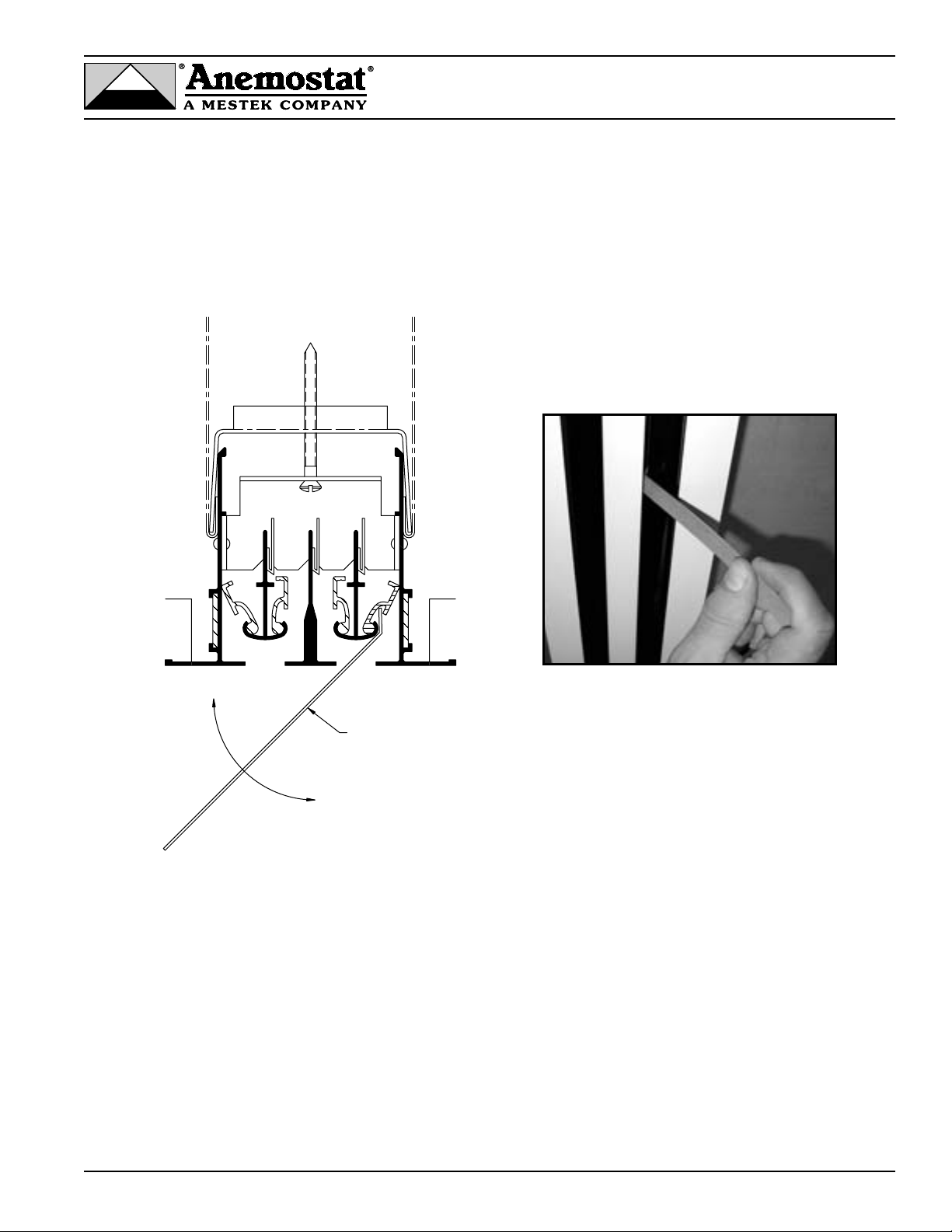
A deflector adjustment tool is provided with each SLAD shipment. The adjustable vanes include an integral slot to allow the tool to
engage the vane, and by rotating the tool as shown, position the vane as required for the pattern and air volume required for the
application.
DEFLECTOR
ADJUSTMENT TOOL
 Loading...