


EZT–IOM–001
3/08
A I R F L O W S O L U T I O N S
E Z T
I n s t a l l a t i o n , O p e r a t i o n , a n d M a i n t e n a n c e
S i n g l e D u c t
V a r i a b l e A i r Vo l u m e Te r m i n a l s

|
1220 Watson Center Road • Carson, CA 90745 |
|
Tel: (310) 835-7500 • Fax: (310) 835-0448 |
|
www.anemostat.com • airhelp@anemostat.com |
Contents |
|
Model Number Description............................................................................................................................................................. |
3 |
Unit Labeling.................................................................................................................................................................................... |
4 |
Receiving and Inspection Instructions............................................................................................................................................ |
5 |
Warnings.......................................................................................................................................................................................... |
5 |
Unit Placement and Installation...................................................................................................................................................... |
6 |
Shipping Weights............................................................................................................................................................................. |
7 |
Clearance Requirements................................................................................................................................................................. |
8 |
Duct Connections and Insulation.................................................................................................................................................... |
8 |
Hot Water Coil Connections............................................................................................................................................................ |
8 |
Electrical Connections..................................................................................................................................................................... |
9 |
Start-up Procedures......................................................................................................................................................................... |
9 |
Maintenance..................................................................................................................................................................................... |
9 |
Factory Mounted DDC Controls.................................................................................................................................................... |
9 |
Airflow Sensor P Versus Air Flow Chart – Pneumatic Controls................................................................................................ |
10 |
Minimum and Maximum Airflow Settings.................................................................................................................................. |
11 |
Altitude Correction Factors........................................................................................................................................................... |
11 |
VDC Signal Versus Airflow Charts – Electronic Analog Controls................................................................................................ |
12 |
2

1220 Watson Center Road • Carson, CA 90745 Tel: (310) 835-7500 • Fax: (310) 835-0448 www.anemostat.com • airhelp@anemostat.com
Model Number Description
Digit 1, 2, 3 – Model |
|
|
|||
EZT |
Single Duct |
|
|
||
Digit 4 – Unit Type |
|
|
|||
S |
Standard |
|
|
||
A |
With integral sound attenuator |
||||
E |
Extended unit for electric coil |
||||
Digit 5, 6 – Inlet Size |
|
|
|||
05 |
5 inch |
|
|
10 |
10 inch |
|
|||||
06 |
6 inch |
|
|
12 |
12 inch |
07 |
7 inch |
|
|
14 |
14 inch |
08 |
8 inch |
|
|
16 |
16 inch |
09 |
9 inch |
|
|
24 |
24 x 16 inch rectangular |
Digit 7 – Casing Construction
A22 gauge steel (standard)
B20 gauge steel
CFibre-Lok 22 gauge steel liner (metal covering insulation edges)
DFibre-Lok 20 gauge steel liner (metal covering insulation edges)
E22 gauge steel double wall (inner liner over 1/2 inch insulation)
F22 gauge steel low temperature casing
Digit 8 – Insulation and Treatment
0None
11/2 inch matte-faced glass fiber (standard)
21 inch matte-faced glass fiber (required with low temperature casing)
31/2 inch foil-faced glass fiber (tape covering insulation edges)
41 inch foil-faced glass fiber (tape covering insulation edges)
53/8 inch closed cell (fiber free)
Digit 9 – Control Type
0 |
None |
P |
Pneumatic - Pressure independent |
N |
Pneumatic - Pressure dependent |
A |
Electronic Analog - Pressure independent |
EElectric - Pressure dependent
FFactory mounted, provided by others
Digit 10, 11, 12, 13 – Control Package Number
0000 None
XXXX Refer to pages 314 thru 317
Digit 14 – Control Location (determined by facing the inlet)
R Right hand (standard) L Left hand
Digit 15, 16, 17, 18 – Minimum Airflow
0000 None specified
XXXXSpecify minimum airflow setting in CFM Refer to pages 314 and 316
Digit 19, 20, 21, 22 – Maximum Airflow
0000 None specified
XXXXSpecify maximum airflow setting in CFM Refer to pages 314 and 316
Digit 23 – Heating Coil and Connection Location (determined by facing the inlet)
0 None
AOne-row hot water - right hand connection
BOne-row hot water - left hand connection
CTwo-row hot water - right hand connection
DTwo-row hot water - left hand connection
GFour-row hot water - right hand connection
HFour-row hot water - left hand connection
JElectric Coil - right hand connection
KElectric Coil - left hand connection
Digit 24 – Line Voltage Transformer
0None
1120 Volt/ 1 phase/ 60 Hz
2208 Volt/ 1 phase/ 60 Hz
3240 Volt/ 1 phase/ 60 Hz
4277 Volt/ 1 phase/ 60 Hz
Digit 25 – Electric Coil Voltage and Steps (location same as controls)
0 None
A208 Volt/ 1 Phase/ 60 Hz 1 Step
B208 Volt/ 1 Phase/ 60 Hz 2 Step
C208 Volt/ 1 Phase/ 60 Hz 3 Step
D240 Volt/ 1 Phase/ 60 Hz 1 Step
E240 Volt/ 1 Phase/ 60 Hz 2 Step
F240 Volt/ 1 Phase/ 60 Hz 3 Step
G277 Volt/ 1 Phase/ 60 Hz 1 Step
H277 Volt/ 1 Phase/ 60 Hz 2 Step
J277 Volt/ 1 Phase/ 60 Hz 3 Step
K208 Volt/ 3 Phase/ 60 Hz 1 Step
L208 Volt/ 3 Phase/ 60 Hz 2 Step
M208 Volt/ 3 Phase/ 60 Hz 3 Step
N480 Volt/ 3 Phase/ 60 Hz 1 Step
P480 Volt/ 3 Phase/ 60 Hz 2 Step
R480 Volt/ 3 Phase/ 60 Hz 3 Step
S120 Volt/ 1 Phase/ 60 Hz 1 Step
T120 Volt/ 1 Phase/ 60 Hz 2 Step
U120 Volt/ 1 Phase/ 60 Hz 3 Step
V240 Volt/ 3 Phase/ 60 Hz 1 Step
W240 Volt/ 3 Phase/ 60 Hz 2 Step
X240 Volt/ 3 Phase/ 60 Hz 3 Step
Y480 Volt/ 1 Phase/ 60 Hz 1 Step
Z480 Volt/ 1 Phase/ 60 Hz 2 Step
1 480 Volt/ 1 Phase/ 60 Hz 3 Step
Digit 26, 27, 28 – Electric Coil KW
000 None
XXX (in 0.5 KW increments)
Digit 29 and over – Options & Accessories
Access options
A1 6” x 6” Bottom access plate (provided with same insulation as the casing)
A2 6” x 6” Bottom access door w/hinge and camlock A3 6” x 6” Bottom removable access door with 2
camlocks
B1 6” x 6” Side access plate (provided with same insulation as the casing on opposite side of controls)
B2 6” x 6” Side access door w/hinge and camlock (opposite side of controls)
B3 6” x 6” Side removable access door with 2 camlocks (opposite side of controls)
Casing options
C1 Unit mounting brackets – shipped loose
C2 Manual damper locking quadrant
C3 Standard Control Enclosure
C4 Universal (larger) control enclosure (must be opposite electric coil connection side)
C5 Hinged front panel for control enclosure
LLLo-Leakage casing (available with only A3 or B3 access doors.
Electric control options
D1 Low voltage control disconnect switch
D2 Low voltage fuse and fuse block
D3 Line voltage SPST disconnect switch (120/1, 277/1 line voltage)
D4 Line voltage DPST disconnect switch (208/1, 230/1, 240/1 line voltage)
D5 Line voltage power-fusing (fuse and fuse block for 120/1, 277/1 line voltage)
D6 Line voltage power-fusing (fuse and fuse block for 208/1, 230/1, 240/1 line voltage)
D9 24 VAC actuator (3 wire / tri-state / fail in place)
Electric heat options
E1 Door interlocking disconnect switch - non-fused
E2 Mercury de-energizing contactors
E3 Power-fusing (Fuses and fuse blocks)
E5 Primary fused transformer
Notes:
Z in any digit indicates a non-catalog special which requires authorization
3
1220 Watson Center Road • Carson, CA 90745 Tel: (310) 835-7500 • Fax: (310) 835-0448 www.anemostat.com • airhelp@anemostat.com
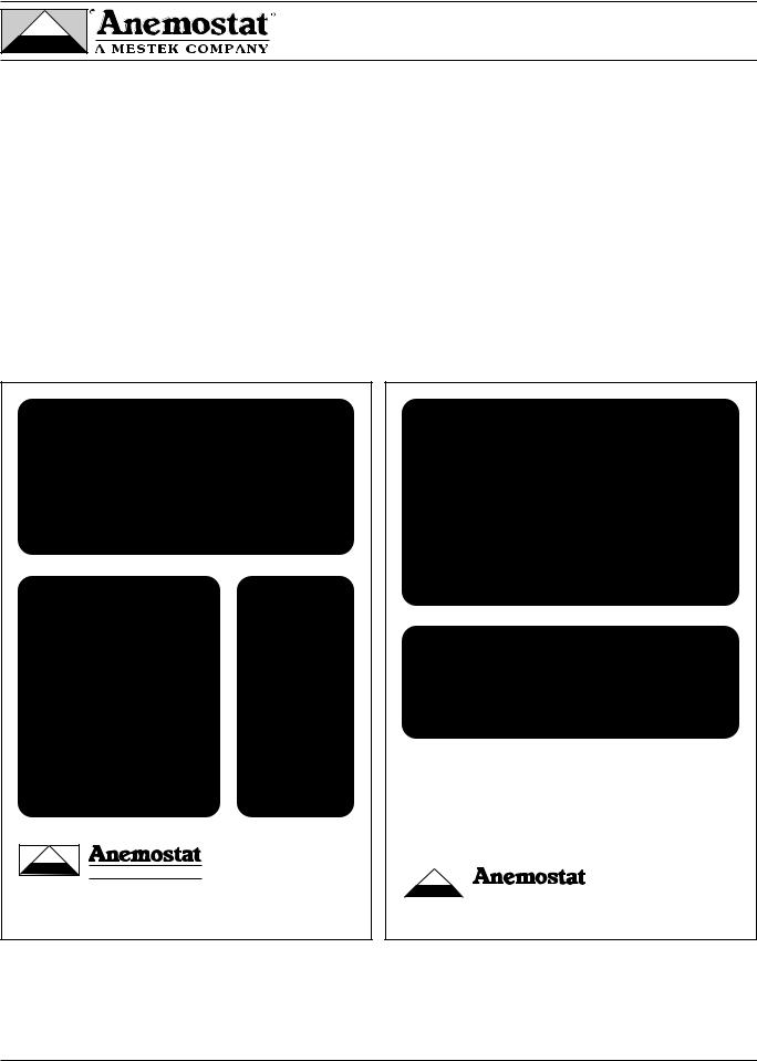
Unit Labeling
Labels are applied to each terminal as follows:
•Unit specific nameplate showing model number, manufactured date, and information regarding controls and heat provided as appropriate.
•The appropriate airflow calibration chart indicating the airflow at varying airflow sensor signals as shown on pages 10, 11, and 12.
•The appropriate wiring/piping diagram for controls provided by Anemostat. Refer to controls manual CM-1 for controls adjustment and troubleshooting procedures.
•Up arrow indicating the proper orientation of the unit for installation.
•Airflow direction arrow indicating the proper orientation of the duct connections.
•ARI logo indicating the units performance is ARI certified.
•Sheet Metal Workers Union logo indicating unit produced by members of The Sheet Metal Workers Union.
 WARNING
HAZARDOUS VOLTAGE!
RISK OF ELECTRIC SHOCK CAN CAUSE INJURY OR DEATH DISCONNECT ALL REMOTE POWER SUPPLIES BEFORE SERVICING
SINGLE DUCT AIR TERMINAL WITH ELECTRIC HEAT
Model: EZTE |
|
Size: XX |
|
Order: XXXXXX |
|
TAG: XXXXXX |
|
|
|
||
Mfg. Date: XX/XX/XX |
|
|
|
Control Package: XXXXX |
|
||
Location: XXXXXXXXXXXXX |
|
||
Heater Data: See heater name plate |
|||
Heater Min. Airflow Req’d: XXX CFM |
|||
DESIGN AIRFLOW RATES / SIGNAL |
|||
Min CFM: |
XXX |
/ |
XX VDC |
Max CFM: |
XXX |
/ |
XX VDC |
Aux CFM: |
XXX |
/ |
XX VDC |
Use copper power supply wiring only
® |
® |
Conforms to |
|
|
|
A MESTEK COMPANY |
|
UL STD 1996 |
|
UL STD 429 |
|
CARSON, CA 310-835-7500 |
|
|
3031533
L-27C1 |
Made in the USA |
Nameplate for terminals with electronic analog controls and/or electric heat
|
|
|
AIR TERMINALS |
Model: EZTS |
|
|
Size: XX |
Order: XXXXXX |
|
|
|
Mfg. Date: XX/XX/XX |
|
|
|
Control Package: XXXXX |
|
||
Location: XXXXXXXXXXXXX |
|||
DESIGN AIRFLOW RATES / SIGNAL |
|||
Min CFM: |
XXX |
/ |
XX VDC |
Max CFM: |
XXX |
/ |
XX VDC |
Aux CFM: |
XXX |
/ |
XX VDC |
TAG:
XXXXXX
|
® |
® |
|
|
|
|
|
A MESTEK COMPANY |
|
|
|
|
|
CARSON, CA 310-835-7500 |
L-54C1 |
|
Made in the USA |
Nameplate for terminals with pneumatic controls without electric heat.
4
 Loading...