

Page 1

AE02B-A3659 Rev -- FUNCTIONAL DESCRIPTION
CHAPTER 3
FUNCTIONAL DESCRIPTION
3.1 OVERVIEW
The SelectAmp Channe l ized Paging Rep eat er accepts inputs i n t he 928 – 9 42 pag ing ba nd, and se lec ti v el y
passes one discrete channel in each band while rejecting the others. In the forward channels this is
accomplished by downconverting the desired signals to a 45 MHz intermediate frequency and using
narrowband crystal filters to provide adjacent channel rejection. The reverse path is not channelized,
passing all frequencies in the 897 – 903 MHz band.
3.2 FUNCTIONAL DESCRIPTION
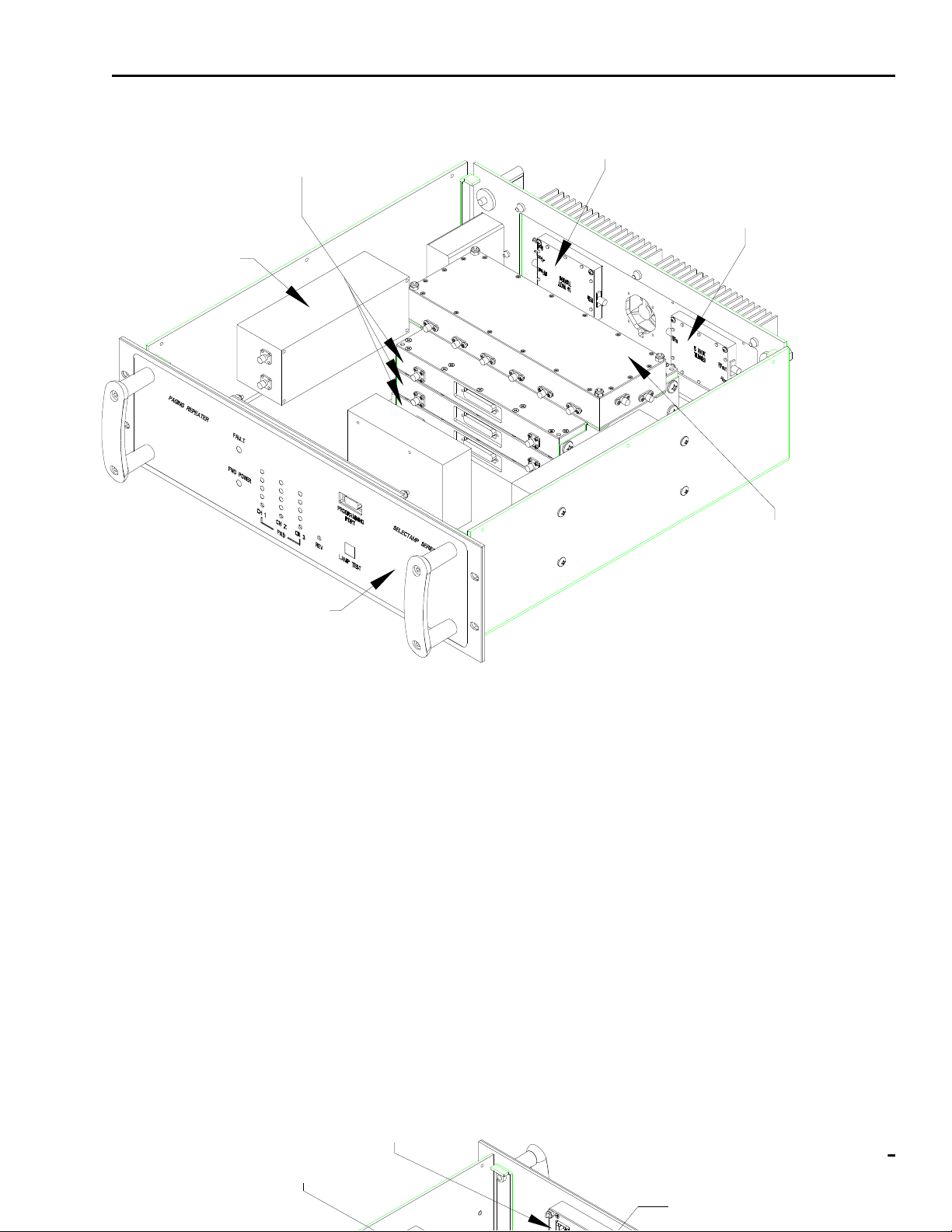
Refer to Figure 3-1. The amplifier contains two paths; forward for the base station to pager signal and
reverse fo r th e pa ge r t o bas e station si gnal. The forwar d pa t h inc lu de s a di pl exer, low no is e am pl i fi er an d
splitter, channelizer, combiner, and power amplifier. The channelizers determine the frequencies to be
amplified and provide the gain control. The reverse path includes a diplexer, broadband module (amplifier
and filters), and a power amplifier. Diplexing of the forward and reverse channels is accomplished by
diplexer filter s tuned to the appropriate frequenci es.
3.2.1 DIPLEXER
The diplexer module consists of dual filters with a common port on one end and two separate ports on the
other. One side of the diplexer is tuned for the forward channel, the other side for the reverse channel.
Insertion loss of each filter is 2 dB maximum and 65 dB minimum rejection t o the opposite band.
3.2.2 BROADBAND MODULE
The broadband mo dule conta in s thr ee boar ds , each mount ed in it s ow n comp art men t. The forw ar d chan nel
signals are routed through the LNA/Splitter and Combiner boards. The reverse channel signal is routed
through the 901 MHz board. Each board is described in more detail below.
3.2.2.1 LNA/SPLITTER
The LNA/Splitter module contains the first active devi ces in the forward channel pat h. It consis ts of a low
noise amplifier, 3-way power splitter, and a gain stage and filter per path. The amplifiers bias voltages are
monitored for a fault condition and reported to the control/distribution module.
3.2.2.2 COMBINER
The Combiner module consists of a 3-way power combiner, a gain stage and filter, and a level detector
circuit.
Document use is restricted to that described on cover 3-1
Page 2
AE02B-A3659 Rev -- FUNCTIONAL DESCRIPTION
REV CHANNEL PA (A10)
CHANNELIZERS (A4,A5,A6)
FWD CHANNEL PA (A12)
DIPLEXER (A8)
BROADBAND (A7)
FRONT PANEL (A13)
Figure 3-1. SelectAmp NBPCS-900-3 Outline Drawing, front view.
3.2.2.3 901 MHZ REVERSE CHANNEL
The 901 MHz reverse ch annel modul e prov ides four gain st ages, fi l t eri ng, and gai n adj ustm ent v ia t he front
panel.
3.2.3 CHANNELIZER
The channelizer module contains three boards, each mounted in their own compartment. These three
boards, which are described below, provide the channel selectivity. The channelizer module gain is
approximately 40 dB.
CONTROL/DISTRIBUTION (A1)
Document use is restricted to that described on cover 3-2
DIPLEXER (A9)
POWER SUPPLY (A2)
Page 3

AE02B-A3659 Rev -- FUNCTIONAL DESCRIPTION
Figure 3-2. SelectAmp NBPCS-900-3 Out line Drawing, rear v iew.
3.2.3.1 DOWNCONVERTER
The downconverter board consists of a mixer driven by a synthesizer, a crystal filter centered at 45 MHz
with either a 12.5 KHz (930 MHz channelizer), a 50 KHz (940 MHz ReFlex50 channelizer), or a 25 KHz
(940 MHz ReFlex25 channelizer) 1 dB bandwidth. It has one fixed gain stage, and a variable gain stage
to provide overall gain adjustment. A Receive Signal Strength Indicator (RSSI) circuit measures the
received signal strength and output s a dc voltage to the Control/Dist ribution board. The DC current draw
of each gain stage is monitored by a window comparator. The wind ow comparator indicates a fault, if the
gain stage has an open or short condition. The output of the down converter is fed to the upconverter
board.
Document use is restricted to that described on cover 3-3
Page 4

AE02B-A3659 Rev -- FUNCTIONAL DESCRIPTION
3.2.3.2 UPCONVERTER
The upconverter board mixes the filtered 45 MHz IF with a signal from the synthesizer and outputs the
same frequency that w as inp ut to t he dow nconver t er. The upconver te r consi sts o f a mix er, gain st age, and
filter. The DC current draw of each gain stage is monitored by a window comparator. The window
comparator indicates a fault, if the gain stage has an open or short condit ion.
3.2.3.3 SYNTHESIZER
The synthes iz er bo ard consis ts of a synthesiz e r cir cui t th at is driv en by a referen ce oscil la tor and dist r ibut ion
amplifiers. The synthesizer operati ng frequency is programmed from the Control/Distr ibuti on module. The
forward channel frequencies are set wit h a computer t hat has Andrew desi gned frequency control software
installed on it. This software is a Microsoft Windows 95/98/NT application that allows the operator to input
the desired channel frequency. The Control/Distribution module converts the operator's input to the
appropriate frequency command for the synthesizer. The output of the synthesizer is divided into a
downconverter path and an upconv erter path.
3.2.4 POWER SUPPLY
The power supply assembly consists of a Power Entry Module and switching power supply. The power
supply a ccept s a
Power is distribut ed to the active modules through the Control/Distribution board.
100 to 240 VAC, 3A, 50 /60 Hz i nput and outputs + 15 VDC fo r use by the res t of t he ampl ifi er .
3.2.5 CONTROL/DISTRIBUTION MODULE
The control/distribution module distributes power to the other modules, receives and processes status and
fault information, and provides forward channel frequency control. Power distribution consists of current
monitoring of both the forward and reverse channel PA’s, li nearly regulating the +15 VDC down to +12 and
+5 VDC for various modules. Status functions include monitoring RSSI voltages from the channelizers,
monitoring forward output power, and driving the appropriate front panel LED’s. Channel frequency
selection information is received via RS-232 from the front panel and is processed by an on board
microcontroller. This i nformation is also stored in ROM (Read Only Memor y), so that frequency settings
are not lost if AC input power is lost. The mic rocontroller sends the frequenc y information via a thr ee wire
interface to the appropriate channelizer. Various faults on the channelizers, broadband, and the
control/distribution module itself are monitored and displayed on the front panel. A rear panel contact
closure (closed when unit i s operating normally ) is provided for exter nal monitoring.
3.2.6 POWER AMPLIFIER MODULES
The power amplifier module provides the final gain and power stages for the amplifier. A 5 Watt Peak Class
A linear amplifier is used for the forward channel. This 5 Watt unit has approximately 27 dB gain. A 1.6
Watt Peak Class A linear amplifier is used for the rever se channel. The 1.6 Watt unit has approximately
30 dB gain. The DC current draw of each power amplifer is monitored by a window comparator.
Document use is restricted to that described on cover 3-4
Page 5

AE02B-A3659 Rev -- FUNCTIONAL DESCRIPTION
3.3 PROGRAMMING
The amplifier forward channels are set by connecting a laptop computer wi th t he suppli ed cable t o t he front
panel connector.
Details on setting the channels and software operation are provided in Appendix B.
Document use is restricted to that described on cover 3-5
 Loading...