


Installation, Operation and Maintenance
Type ES37( )
3.7-Meter ESA
Bulletin OM37
Revision C
3.7-Meter Earth Station Antenna
Andrew Corporation |
Telephone: 708-349-3300 |
Customer Service, 24 hours: U.S.A. • Canada • Mexico: 1-800-255-1479 |
|||
10500 West 153rd Street |
FAX (U.S.A.): 1-800-349-5444 |
U.K.: 0800 250055 • Republic of Ireland: 1 800 535358 |
Printed in U.S.A. 9/00 |
||
Orland Park, IL U.S.A. 60462 |
Internet: http://www.andrew.com |
Other Europe: +44 1592 782612 |
|
||
Copyright © 2000 by Andrew Corporation |
|||||
|
|
|
|||

Table of Contents
Introduction
How to Use This Manual Getting Started
Installation
Procedures
Operation
Preventive
Maintenance
Introduction . . . . . . . . . . . . . . . . . . . . . . . . . . . . . . . . . . . . . . . . . . . . . . . . . . . . . . . . . . . . . . . . . . . . . . . . . . 3 Proprietary Data . . . . . . . . . . . . . . . . . . . . . . . . . . . . . . . . . . . . . . . . . . . . . . . . . . . . . . . . . . . . . . . . . . 4 Information and Assistance . . . . . . . . . . . . . . . . . . . . . . . . . . . . . . . . . . . . . . . . . . . . . . . . . . . . . . . . . 4 Notice . . . . . . . . . . . . . . . . . . . . . . . . . . . . . . . . . . . . . . . . . . . . . . . . . . . . . . . . . . . . . . . . . . . . . . . . . . 4 Technical Assistance . . . . . . . . . . . . . . . . . . . . . . . . . . . . . . . . . . . . . . . . . . . . . . . . . . . . . . . . . . . . . . 4
Overview . . . . . . . . . . . . . . . . . . . . . . . . . . . . . . . . . . . . . . . . . . . . . . . . . . . . . . . . . . . . . . . . . . . . . . . . . . . . 5 Content . . . . . . . . . . . . . . . . . . . . . . . . . . . . . . . . . . . . . . . . . . . . . . . . . . . . . . . . . . . . . . . . . . . . . . . . . 5 Overview . . . . . . . . . . . . . . . . . . . . . . . . . . . . . . . . . . . . . . . . . . . . . . . . . . . . . . . . . . . . . . . . . . . . . . . . . . . . 6 Warnings . . . . . . . . . . . . . . . . . . . . . . . . . . . . . . . . . . . . . . . . . . . . . . . . . . . . . . . . . . . . . . . . . . . . . . . . 6 Recommended Tools . . . . . . . . . . . . . . . . . . . . . . . . . . . . . . . . . . . . . . . . . . . . . . . . . . . . . . . . . . . . . . 7 Parts Verification . . . . . . . . . . . . . . . . . . . . . . . . . . . . . . . . . . . . . . . . . . . . . . . . . . . . . . . . . . . . . . . . . . 8 Reporting Equipment Loss or Damage . . . . . . . . . . . . . . . . . . . . . . . . . . . . . . . . . . . . . . . . . . . . . . . . 8 Reporting Visible Loss or Damage. . . . . . . . . . . . . . . . . . . . . . . . . . . . . . . . . . . . . . . . . . . . . . . . . . . . 8 Reporting Concealed Damage. . . . . . . . . . . . . . . . . . . . . . . . . . . . . . . . . . . . . . . . . . . . . . . . . . . . . . . . 8 Inventory Equipment Received . . . . . . . . . . . . . . . . . . . . . . . . . . . . . . . . . . . . . . . . . . . . . . . . . . . . . . 8 Returning Equipment . . . . . . . . . . . . . . . . . . . . . . . . . . . . . . . . . . . . . . . . . . . . . . . . . . . . . . . . . . . . . . 9 Installation Sequence Checklist . . . . . . . . . . . . . . . . . . . . . . . . . . . . . . . . . . . . . . . . . . . . . . . . . . . . . . 10 Site Preparation. . . . . . . . . . . . . . . . . . . . . . . . . . . . . . . . . . . . . . . . . . . . . . . . . . . . . . . . . . . . . . . . . . . 10 Ground Mount Assembly. . . . . . . . . . . . . . . . . . . . . . . . . . . . . . . . . . . . . . . . . . . . . . . . . . . . . . . . . . . . 10 For MPK Types Only . . . . . . . . . . . . . . . . . . . . . . . . . . . . . . . . . . . . . . . . . . . . . . . . . . . . . . . . . . . . . . . 10 For MPJK Types Only . . . . . . . . . . . . . . . . . . . . . . . . . . . . . . . . . . . . . . . . . . . . . . . . . . . . . . . . . . . . . . 11 Main Reflector Assembly . . . . . . . . . . . . . . . . . . . . . . . . . . . . . . . . . . . . . . . . . . . . . . . . . . . . . . . . . . . 11 Enclosure Assembly . . . . . . . . . . . . . . . . . . . . . . . . . . . . . . . . . . . . . . . . . . . . . . . . . . . . . . . . . . . . . . . 12 Reflector-To-Mount Assembly . . . . . . . . . . . . . . . . . . . . . . . . . . . . . . . . . . . . . . . . . . . . . . . . . . . . . . . 12 Subreflector . . . . . . . . . . . . . . . . . . . . . . . . . . . . . . . . . . . . . . . . . . . . . . . . . . . . . . . . . . . . . . . . . . . . . 13 Feed System . . . . . . . . . . . . . . . . . . . . . . . . . . . . . . . . . . . . . . . . . . . . . . . . . . . . . . . . . . . . . . . . . . . . . 13
Overview . . . . . . . . . . . . . . . . . . . . . . . . . . . . . . . . . . . . . . . . . . . . . . . . . . . . . . . . . . . . . . . . . . . . . . . . . . . . 14 Foundation Preparation . . . . . . . . . . . . . . . . . . . . . . . . . . . . . . . . . . . . . . . . . . . . . . . . . . . . . . . . . . . . 14 A-325 Tensioning . . . . . . . . . . . . . . . . . . . . . . . . . . . . . . . . . . . . . . . . . . . . . . . . . . . . . . . . . . . . . . . . . 15 Mount . . . . . . . . . . . . . . . . . . . . . . . . . . . . . . . . . . . . . . . . . . . . . . . . . . . . . . . . . . . . . . . . . . . . . . . . . . 16 Unpacking . . . . . . . . . . . . . . . . . . . . . . . . . . . . . . . . . . . . . . . . . . . . . . . . . . . . . . . . . . . . . . . . . . . . . . . 16 Assembly (Using a Crane) . . . . . . . . . . . . . . . . . . . . . . . . . . . . . . . . . . . . . . . . . . . . . . . . . . . . . . . . . . 16 Assembly (Without a Crane) . . . . . . . . . . . . . . . . . . . . . . . . . . . . . . . . . . . . . . . . . . . . . . . . . . . . . . . . .19 Motorizable Pedestal Ground Mount Assembly . . . . . . . . . . . . . . . . . . . . . . . . . . . . . . . . . . . . . . . . . .22 Manual Pedestal Ground Mount Assembly. . . . . . . . . . . . . . . . . . . . . . . . . . . . . . . . . . . . . . . . . . . . . . 24 Manual Actuator Assembly . . . . . . . . . . . . . . . . . . . . . . . . . . . . . . . . . . . . . . . . . . . . . . . . . . . . . . . . . 32 Manual Actuator Assembly Removal. . . . . . . . . . . . . . . . . . . . . . . . . . . . . . . . . . . . . . . . . . . . . . . . . . 33 Motorizable Pedestal Ground Mount Assembly . . . . . . . . . . . . . . . . . . . . . . . . . . . . . . . . . . . . . . . . . .33 Embedded Pipe Ground Mount Assembly . . . . . . . . . . . . . . . . . . . . . . . . . . . . . . . . . . . . . . . . . . . . . . 38 Elevation/Azimuth Strut Assembly . . . . . . . . . . . . . . . . . . . . . . . . . . . . . . . . . . . . . . . . . . . . . . . . . . . .39 Reflector . . . . . . . . . . . . . . . . . . . . . . . . . . . . . . . . . . . . . . . . . . . . . . . . . . . . . . . . . . . . . . . . . . . . . . . . 43 Unpacking . . . . . . . . . . . . . . . . . . . . . . . . . . . . . . . . . . . . . . . . . . . . . . . . . . . . . . . . . . . . . . . . . . . . . . . 43 Assembly . . . . . . . . . . . . . . . . . . . . . . . . . . . . . . . . . . . . . . . . . . . . . . . . . . . . . . . . . . . . . . . . . . . . . . . 45 Alignment Test . . . . . . . . . . . . . . . . . . . . . . . . . . . . . . . . . . . . . . . . . . . . . . . . . . . . . . . . . . . . . . . . . . . 51 Enclosure (Pedestal Mount Only) . . . . . . . . . . . . . . . . . . . . . . . . . . . . . . . . . . . . . . . . . . . . . . . . . . . . .52 Reflector-to-Mount Assembly . . . . . . . . . . . . . . . . . . . . . . . . . . . . . . . . . . . . . . . . . . . . . . . . . . . . . . . .55 Using a Crane . . . . . . . . . . . . . . . . . . . . . . . . . . . . . . . . . . . . . . . . . . . . . . . . . . . . . . . . . . . . . . . . . . . . 55 Without a Crane . . . . . . . . . . . . . . . . . . . . . . . . . . . . . . . . . . . . . . . . . . . . . . . . . . . . . . . . . . . . . . . . . . 57 Reflector-to-Mount Assembly, Embedded Pipe Ground Mount . . . . . . . . . . . . . . . . . . . . . . . . . . . . . 62 Subreflector . . . . . . . . . . . . . . . . . . . . . . . . . . . . . . . . . . . . . . . . . . . . . . . . . . . . . . . . . . . . . . . . . . . . . 63 Subreflector Struts, Embedded Pipe Ground Mount . . . . . . . . . . . . . . . . . . . . . . . . . . . . . . . . . . . . . . 67 Subreflector Adjustment . . . . . . . . . . . . . . . . . . . . . . . . . . . . . . . . . . . . . . . . . . . . . . . . . . . . . . . . . . . .68 Feed System . . . . . . . . . . . . . . . . . . . . . . . . . . . . . . . . . . . . . . . . . . . . . . . . . . . . . . . . . . . . . . . . . . . . . 70
Overview . . . . . . . . . . . . . . . . . . . . . . . . . . . . . . . . . . . . . . . . . . . . . . . . . . . . . . . . . . . . . . . . . . . . . . . . . . . . 71 Acquiring A Satellite . . . . . . . . . . . . . . . . . . . . . . . . . . . . . . . . . . . . . . . . . . . . . . . . . . . . . . . . . . . . . . . 71 Manual Actuator Assembly Removal . . . . . . . . . . . . . . . . . . . . . . . . . . . . . . . . . . . . . . . . . . . . . . . . . . 75 Embedded Pipe Ground Mount Elevation Adjustment . . . . . . . . . . . . . . . . . . . . . . . . . . . . . . . . . . . . 75 Azimuth Adjustment . . . . . . . . . . . . . . . . . . . . . . . . . . . . . . . . . . . . . . . . . . . . . . . . . . . . . . . . . . . . . . . 75 Conclusion . . . . . . . . . . . . . . . . . . . . . . . . . . . . . . . . . . . . . . . . . . . . . . . . . . . . . . . . . . . . . . . . . . . . . . 75 Subreflector Adjustment . . . . . . . . . . . . . . . . . . . . . . . . . . . . . . . . . . . . . . . . . . . . . . . . . . . . . . . . . . . .76
Overview. . . . . . . . . . . . . . . . . . . . . . . . . . . . . . . . . . . . . . . . . . . . . . . . . . . . . . . . . . . . . . . . . . . . . . . . . . . . .77 General Cleaning . . . . . . . . . . . . . . . . . . . . . . . . . . . . . . . . . . . . . . . . . . . . . . . . . . . . . . . . . . . . . . . . . 77 Electrical Parts. . . . . . . . . . . . . . . . . . . . . . . . . . . . . . . . . . . . . . . . . . . . . . . . . . . . . . . . . . . . . . . . . . . .77 Mechanical Parts. . . . . . . . . . . . . . . . . . . . . . . . . . . . . . . . . . . . . . . . . . . . . . . . . . . . . . . . . . . . . . . . . . 78 Inspection . . . . . . . . . . . . . . . . . . . . . . . . . . . . . . . . . . . . . . . . . . . . . . . . . . . . . . . . . . . . . . . . . . . . . . . 78 Local Control/Motor Drive Controller. . . . . . . . . . . . . . . . . . . . . . . . . . . . . . . . . . . . . . . . . . . . . . . . . . 78 Antenna . . . . . . . . . . . . . . . . . . . . . . . . . . . . . . . . . . . . . . . . . . . . . . . . . . . . . . . . . . . . . . . . . . . . . . . . . 79 Drive System Voltage and Current Checks. . . . . . . . . . . . . . . . . . . . . . . . . . . . . . . . . . . . . . . . . . . . . .81 Pedestal Mount Bearing Pad Adjustment . . . . . . . . . . . . . . . . . . . . . . . . . . . . . . . . . . . . . . . . . . . . . . 82 Preservation of Component Parts. . . . . . . . . . . . . . . . . . . . . . . . . . . . . . . . . . . . . . . . . . . . . . . . . . . . . 83 Aluminum Parts . . . . . . . . . . . . . . . . . . . . . . . . . . . . . . . . . . . . . . . . . . . . . . . . . . . . . . . . . . . . . . . . . . 83 Galvanized Surfaces . . . . . . . . . . . . . . . . . . . . . . . . . . . . . . . . . . . . . . . . . . . . . . . . . . . . . . . . . . . . . . . 83 Lubrication . . . . . . . . . . . . . . . . . . . . . . . . . . . . . . . . . . . . . . . . . . . . . . . . . . . . . . . . . . . . . . . . . . . . . . 83 Jackscrews/Motors . . . . . . . . . . . . . . . . . . . . . . . . . . . . . . . . . . . . . . . . . . . . . . . . . . . . . . . . . . . . . . . . 84 Gear Motor/Housing Fill Drain Requirements. . . . . . . . . . . . . . . . . . . . . . . . . . . . . . . . . . . . . . . . . . . . 84
2 |
Table of Contents |

3.7-Meter Earth Station Antenna
Introduction |
|
Like all Andrew earth station antennas, the 3.7-Meter Earth Station Antenna provides |
|
||
|
|
high gain and exceptional pattern characteristics. The electrical performance and excep- |
|
|
tional versatility provides the ability to configure the antenna with your choice of linearly- |
|
|
polarized 2-port or 4-port combining network. That versatility is provided at the time of |
|
|
initial purchase, as well as in the future, as your satellite communication requirements |
|
|
evolve. |
|
|
The aluminum reflector is precision formed for accuracy and strength requiring minimal |
|
|
assembly. The versatile pedestal mount can be purchased with either manual or motor- |
|
|
izable capabilities. The pedestal mount features 180 degree azimuth coverage in three |
|
|
continuous 120 degree overlapping ranges and executes 90 degree continuous eleva- |
|
|
tion adjustment. This large adjustment range provides non-critical foundation orientation |
|
|
and the ability to view geostationary satellites from horizon-to-horizon, from any location |
|
|
worldwide. |
|
|
The motorizable pedestal mount features self-aligning bearings for the elevation pivots, |
|
|
resulting in "zero" backlash. This mount can be operated manually, but has the ability to |
|
|
be upgraded for motorized operation, including steptracking/Smartrack™ applications. |
|
|
The motorizable mount type is indicated by the ES37MPK or ES37MPJK letters within |
|
|
the antenna type number. The addition of the letter "J" within the antenna type number |
|
|
indicates that the mount includes azimuth/elevation machine jackscrews, instead of cor- |
|
|
responding azimuth/elevation strut assemblies. The azimuth/elevation jackscrews are |
|
|
equipped for integration with the optional motor drive systems. |
|
|
A manual pedestal mount is also available. It provides the same strong and versatile |
|
|
combination of mechanical features as the motorizable version; except that the elevation |
|
|
and azimuth axes are locking types, instead of bearing mounted types. This mount type |
|
|
is always equipped with manual struts and a fixed mount for the separately-ordered |
|
|
combining network. This mount has been designed for manual applications only and |
|
|
cannot be upgraded to a motorizable mount. |
|
|
The aluminum enclosure and hot-dipped galvanized steel mount maintain pointing accu- |
|
|
racy and ensures durability and reliability. The antenna and standard manual mount with |
|
|
enclosure will survive 125 mph (200 km/h) wind, in any position of operation, without |
|
|
damage or permanent deformation in moderate coastal/industrial areas. Severe condi- |
|
|
tions require additional protection. |
|
|
Andrew provides a complete line of available options, including field-installed electrical |
|
|
anti-icing heaters, motor drive systems (with power interfaces addressing domestic and |
|
|
international standards), remote microprocessor antenna control for motor drive sys- |
|
|
tems, pressurization equipment, and interconnecting HELIAX® cables and waveguide. |
|
|
|
3 |
Introduction |

Proprietary Data
Information and
Assistance
Notice
Technical
Assistance
The technical data contained herein is proprietary to Andrew Corporation. It is intended for use in operation and maintenance of Andrew supplied equipment. This data shall not be disclosed or duplicated in whole or in part without express written consent of Andrew Corporation.
Andrew Corporation provides a world-wide technical support network. Refer to the technical assistance portion of this this manual for the contact numbers appropriate to your location.
The installation, maintenance, or removal of antenna systems requires qualified, experienced personnel. Andrew installation instructions have been written for such personnel. Antenna systems should be inspected by qualified personnel to verify proper installation, maintenance and condition of equipment.
Andrew Corporation disclaims any liability or responsibility for the results of improper or unsafe installation and maintenance practices.
All designs, specifications, and availabilities of products and services presented in this manual are subject to change without notice.
Copyright © 1999, Andrew Corporation
24-hour Technical Assistance
For technical assistance, call the following numbers at anytime.
Call From |
Call To |
Telephone |
Fax |
|
|
|
|
North America (toll free) |
U. S. A. |
1-(800)-255-1479 |
(800)-349-5444 |
|
|
|
|
Any Location |
U. S. A. |
(708)-349-3300 |
(708)-349-5410 |
(International) |
|
|
|
Customer Service Center
The Andrew Customer Service Center gives you direct access to the information and personnel service you need, such as the following:
•Place or change orders
•Check price and delivery information
•Request technical literature
You can call from any of the following:
Call From |
Telephone |
Fax |
North America |
1-800-255-1479 (toll free) |
1-(800)-349-5444 (toll free) |
|
|
|
United Kingdom |
00-800-0-255-1479 (toll free) |
00-800-0-349-5444 (toll free) |
|
|
|
Australia |
0011-800-0-255-1479 (toll free) |
0011-800-0-349-5444 (toll free) |
|
|
|
China |
00-800-0-255-1479 (toll free) |
00-800-0-349-5444 (toll free) |
|
|
|
New Zealand |
00-800-0-255-1479 (toll free) |
00-800-0-349-5444 (toll free) |
|
|
|
Hong Kong |
001-800-0-255-1479 (toll free) |
001-800-0-349-5444 (toll free) |
|
|
|
|
4 |
Introduction |

How to Use This Manual
Overview
Content
The scope of this manual is intended to provide station personnel with the base installation, operation, and maintenance requirements necessary for a 3.7-Meter C- or Ku-Band Earth Station Antenna. This manual provides a convenient reference for authorized operator/service personnel requiring technical information on general system or specific subsystem equipment.
The tables and figures presented in this manual are used as communication aids for the installation, operation, and maintenance of the 3.7-Meter Earth Station Antenna. These tables and figures instantly convey messages, as well as make the procedures easier to understand. This manual uses tables and figures for the following references:
•Tables The tables allow you to locate information quickly and easily.
•Drawings The drawings supplement the installation instructions by using a combi-
nation of graphics and verbage to assist you in simplifying complex procedures and clarifying components.
• Photographs The photographs compliment the installation instructions by providing
actual examples of the steps being performed, which allow you to view the installation in concrete form.
The manual is divided into five distinct sections, each dealing with a specific technical topic relating to either system or component subsystem information. The sections contained in this manual are described and listed under the following technical headings:
• How to Use Describes the manual's purpose, content, and communication aids.
This Manual Additionally, this section lists the related documentation for the 3.7- Meter Earth Station Antenna.
• Getting Provides the preliminary information needed to perform a successful
Started installation. This section should be reviewed prior to the installation. The warnings, recommended tools, parts verification, instructions on reporting lost or damaged equipment, and installation checklist are located in this section.
• Installation Provides the procedures for the different phases of a 3.7-Meter Earth
Procedures Station Antenna base installation. This section will help you easily find requirements for an individual task, as well as displays the sequence for each task execution.
• Operation Describes the controls, functions, and general operating procedures
required for proper operation of the 3.7-Meter Andrew Earth Station Antenna.
• Preventive Describes preventive maintenance procedures that are required to
Maintenance maintain proper functional operation of your new Andrew Earth Station Antenna.
5 |
How to Use This Manual |

Getting Started
Overview |
|
The installation, operation, and maintenance of the 3.7-Meter Earth Station Antenna |
|
|
|||
|
|
requires qualified and experienced personnel. Andrew installation, operation, and main- |
|
|
|
tenance instructions are illustrated for such personnel. Additionally, the antenna should |
|
|
|
be inspected by qualified personnel to verify proper installation, maintenance, and con- |
|
|
|
dition of equipment as described in Preventive Maintenance. The basic equipment and |
|
|
|
accessories are either manufactured or design controlled by Andrew Corporation. |
|
|
|
The prerequisite information necessary for the 3.7-Meter Earth Station Antenna can be |
|
|
|
found in this section. Furthermore, this section should be reviewed BEFORE performing |
|
|
|
the installation, operation, or maintenance. Warnings, recommended tools, and the |
|
|
|
antenna parts can be verified and/or determined with such a review. |
|
Warnings |
|
When installing the 3.7-Meter Earth Station Antenna, be conscious of the warnings pre- |
|
|
|
sented below. For further information or clarification of this information, contact the |
|
|
|
Customer Service Center. The warnings are as follows: |
|
|
|
1. |
Electrical shock from voltages used in this antenna system may cause personal injury |
|
|
or death. Prior to making any electrical connections or performing maintenance or |
|
|
|
repair, ensure that the power is removed. Electrical connections should be made only by |
|
|
|
qualified personnel in accordance with local regulations. |
|
|
|
2. |
Installation of antennas may require persons to work at elevated work stations. |
|
|
Whenever persons are working at eight or more feet above the ground and not on a |
|
|
|
guarded platform, they should wear safety belts with at least one (preferably two) lan- |
|
|
|
yards. |
|
|
|
3. |
Never stand underneath any object while it is being lifted. |
|
|
4. |
Always wear a hard hat, especially if someone is above you. |
|
|
5. |
Make sure no person is in or under the reflector while it is being lifted or positioned; |
|
|
personal injury can result if the reflector assembly falls. |
|
|
|
6. |
Personnel should never be hoisted in or out of the reflector by the crane; personal |
|
|
injury may result. |
|
|
|
7. |
Andrew earth station antennas supplied to standard product specifications will survive |
|
|
125 mph winds in any operational position in moderate coastal/industrial areas. Severe |
|
|
|
conditions require additional protection. Should it be expected that winds will exceed |
|
|
|
125 mph, it is recommended that Andrew antennas be steered to specific azimuth and |
|
|
|
elevation orientations to minimize wind forces upon the structure and thereby increase |
|
|
|
the probability of survival. |
|
|
|
8. |
It is recommended that all cross-axis waveguide and coaxial cables are secure such |
|
|
that high winds will not cause excessive flexing. Position the antenna to an elevation of |
|
|
|
90 degrees. The azimuth jackscrew should be placed in the center of its travel. |
|
|
|
9. |
When the antenna is transmitting, severe eye injury or injury to other parts of the |
|
|
body can result from exposure to radio frequency (RF) energy. The antenna must be |
|
|
|
turned off before entering the area in front of the reflector and near the feed. |
|
|
|
|
|
6 |
Getting Started |

Recommended
Tools
NOTE: Failure to follow an installation procedure could result in damage to equipment or personal injury.
Additional warnings will be displayed throughout this manual for your awareness. These warnings can be identified in warning boxes as shown in the following sample.
Andrew disclaims any liability or responsibility for the results of improper or unsafe installation, operation, or maintenance practices.
Andrew supplies all appropriate hardware/parts required for the installation of your 3.7- Meter Earth Station Antenna. All tools necessary for the installation process should be provided by the installation crew. Andrew recommends the following tools to be used for a proper installation of the 3.7-Meter Earth Station Antenna.
Tool |
Size |
Quantity |
|
|
|
Open End or Combination Wrenches |
5/16 Inch |
2 |
|
7/16 Inch |
2 |
|
9/16 Inch |
2 |
|
7/8 Inch |
2 |
|
3/4 Inch |
2 |
|
1/2 Inch |
2 |
|
1-1/4 Inch |
1 |
Crane |
1 Ton Minimum Capacity, extended end |
1 |
Nylon Web Slings (2000 pound breaking strength) 3 Inch by 14 Foot |
2 |
|
Rope or Cord (2000 pound breaking strength) |
50 Foot |
1 |
Shackles |
5/8 Inch |
2 |
Ladder |
10 Foot Extension |
1 |
Drive Sockets |
1/16 Inch |
1 |
|
9/16 Inch |
1 |
|
7/8 Inch |
1 |
|
3/4 Inch |
1 |
|
1-1/4 Inch |
1 |
Breaker Bar |
1/2 Inch |
1 |
Spud Wrenches |
1-1/16 Inch |
1 |
|
1-1/4 Inch |
1 |
Screw Driver |
Standard |
1 |
|
Phillips |
1 |
Allen Wrench |
7/64 Inch |
1 |
|
3/16 Inch |
1 |
|
1/4 Inch |
1 |
Tape Measure (or other measuring device) |
Standard |
1 |
Felt-tip Marker (or other marking device) |
Standard |
1 |
Hammer |
Standard |
1 |
Rubber Mallet |
Standard |
1 |
Pry Bar |
Standard |
1 |
Tin Snips |
Standard |
1 |
Safety Gloves (each installer) |
Standard |
1 |
Table 2-1. Recommended Tools
7 |
Getting Started |

Parts Verification
Reporting Equipment Loss or Damage
Reporting Visible Loss or Damage
Reporting
Concealed
Damage
Inventory
Equipment
Received
Upon receipt of your order, the shipment should be verified to ensure that all parts have reached your site. This process should occur before the installation process begins.
Andrew Corporation thoroughly inspects and carefully packs all equipment before shipment. If you find that there are missing components, please refer to page 9 for step-by- step instructions on how to properly report the equipment loss.
When you have received your order, verify that all parts contained in the shipment correspond to the parts listed on your packing list.
If you find that there was damage caused to the equipment during the shipping process, a claim should be filed with the carrier. Follow the "Reporting Visible Loss or Damage" or "Reporting Concealed Damage" procedures when filing a claim with the carrier.
Make a note of any loss or evidence of external damage on the freight bill or receipt, and have it signed by the carrier's agent. Failure to adequately describe such external evidence of loss or damage may result in the carrier refusing to honor a damage claim. The form required to file such a claim will be supplied by the carrier.
Concealed damage means damage which does not become apparent until the unit has been unpacked. The contents may be damaged in transit due to rough handling, even though the carton may not show external damage. If you discover damage after unpacking the unit, make a written request for an inspection by the carrier's agent, then file a claim with the carrier since such damage is most likely the carrier's responsibility.
After opening your shipment, an inventory of the parts should occur immediately. Check each item received in your shipment against the packing slip included with the shipment. If any items are missing, please notify Andrew Corporation immediately by contacting the Customer Service Center.
8 |
Getting Started |

Returning
Equipment
Step 1
Step 2
Step 3
Step 4
Step 5
Andrew Corporation tries to ensure that all items arrive safe and in working order. Occasionally, despite these efforts, equipment is received which is not in working condition. When this occurs, and it is necessary to return the equipment to Andrew Corporation for either repair or replacement, return can be expedited by following the procedure listed below:
Call the Andrew Customer Service Center and request a Return Material Authorization (RM) number, as well as an address to forward the material to.
Tag or identify the defective equipment, noting the defect or circumstances. Also, be sure to write the RM number on the tag. It would be helpful to reference the sales order and purchase order, as well as the date the equipment was received.
Pack the equipment in its original container with protective packing material. If the original container and packing material are no longer available; pack the equipment in a sturdy corrugated box, and cushion it with appropriate packing material.
Be sure to include the following information when returning the equipment:
•Your Company Name
•Your Company Address
•City, State, and Zip Code
•Telephone Number
•RM Number
•Problem Description
•Contact Name
NOTE: Absence of the RM number will cause a delay in processing your equipment for repair. Be sure to include the RM number on all correspondence.
Ship the equipment to Andrew Corporation using UPS, U.S. Postal Service, or other appropriate carrier; freight prepaid and insured. The material should be forwarded to the address given by the Andrew contact in Step 1.
9 |
Getting Started |

Installation
Sequence
Checklist
Site Preparation
Ground Mount
Assembly
For MPK Types
Only
The 3.7-Meter Earth Station Antenna requires the installation team to perform the assembly in the sequence presented below. Moreover, this sequence should be reviewed to ensure a smooth installation. Use the following checklist to verify and/or determine the installation sequence.
Refer to Foundation Section for guidance in preparing location and installation of the 3.7-Meter Earth Station Antenna foundation.
Unpack ground mount assembly
Attach ground mount assembly to foundation
Organize ground mount hardware
Wax galvanized hardware in hardware kit
Tighten ground mount hardware to foundation
Attach azimuth strut weldment to ground mount assembly
Assemble azimuth strut
Mount azimuth strut to ground mount assembly
Bolt elevation strut brackets to elevation strut
Mount elevation strut to ground mount assembly
Assemble manual actuator
Remove manual actuator (after elevation/azimuth adjustment)
10 |
Getting Started |
For MPJK Types
Only
Main Reflector
Assembly
Mount azimuth pivot assembly to ground mount assembly
Bolt one jack to azimuth pivot assembly
Unscrew jack
Tighten galvanized hardware using A-325 tensioning procedure
Lubricate jackscrews
Pull protective boot over jackscrew
Bolt elevation pivot assembly brackets to ground mount assembly
Bolt second jack to elevation pivot assembly
Unscrew jack
Tighten galvanized hardware using A-325 tensioning procedure
Lubricate jackscrews
Pull boot over jackscrew
Remove protective covering from crate
Pry top crate panel off
Pry sides off crate
Pry front off crate
Unbolt reflector halves from bottom of crate
Prepare assembly area with blocks of wood to assemble reflector
Lay reflector halves on prepared assembly area
Align reflector halves
Insert all hardware as outlined in Installation Procedures
11 |
Getting Started |

Enclosure
Assembly
Reflector-To-
Mount Assembly
Add reflector-mounting ring
Mount front and back hub-mounting rings
Apply sealant to outside of reflector-mounting ring
Perform recommended string test
Remove rear and side covers from enclosure assembly
Attach enclosure to mounting ring
Apply sealant backing rod around enclosure/mounting ring mating surfaces
Apply RTV sealant
Route sling through upper holes of torsion box assembly
Route two rope tag lines through torsion box assembly to be used as guides
Place foam blocks on ground to avoid scraping reflector when lifted
Raise reflector
Bolt left bolt of enclosure bracket
Rotate reflector to align right bolt
Extend elevation strut or jackscrew, and attach to top of enclosure assembly
Tighten hardware using A-325 tensioning procedure
Carefully raise reflector to zenith position
Remove hoisting apparatus
12 |
Getting Started |

Subreflector |
|
Preassemble subreflector weldment |
|
||
|
|
Attach subreflector-mounting ring to strut assembly |
|
|
Attach angle clips |
|
|
Attach subreflector to reflector |
|
|
Adjust subreflector |
|
|
Tighten adjustment hardware |
Feed System |
|
Refer to installation instructions packaged with the individual feed systems |
|
|
|
13 |
Getting Started |
Installation Procedures
Overview
Foundation
Preparation
This section provides installation procedures for the 3.7-Meter Andrew Earth Station Antenna. The installation procedures include instructions on the following antenna components:
•Mount
•Reflector
•Enclosure
•Reflector-to-Mount Assembly
•Subreflector
•Feed System (Refer to installation instructions packaged with the individual feed systems)
Before beginning the installation process on the ground mount assembly, ensure that the foundation has been prepared. Foundation specifications are provided by Andrew and may be used as a reference by civil engineering personnel when preparing the foundation for local soil conditions. These specifications are available before the shipment arrives by contacting the Customer Service Center.
Sweep foundation clean of any dirt or debris.
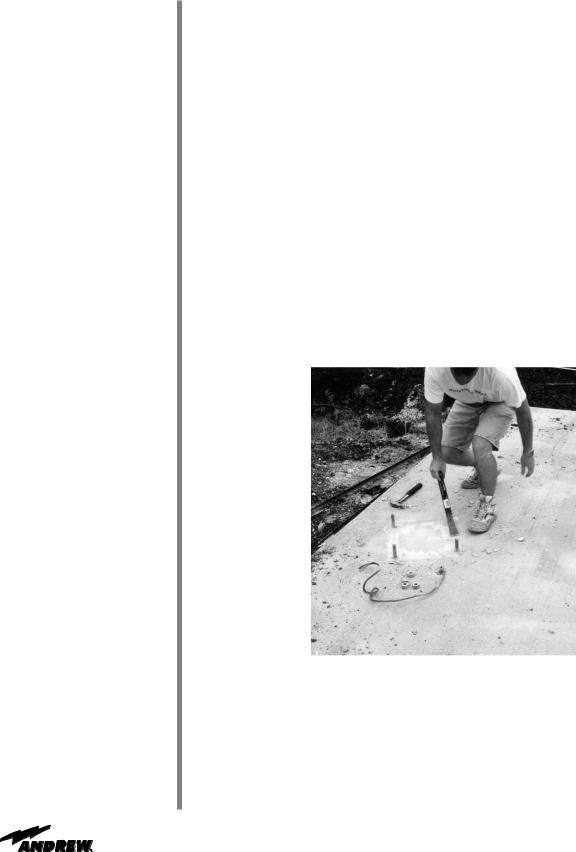
To ensure level, smooth surface for mount, remove excess concrete from shear caps and anchor bolts as shown in Figure 3-1.
Figure 3-1
14 |
Installation Procedures |

A-325 Tensioning
Step 1
Step 2
Step 3
Step 4
Step 5
Step 6
During the installation process, there are several references to the A-325 hardware tensioning procedure. The A-325 hardware must be properly tensioned to avoid slippage between bolted surfaces under high loads. Slippage can cause the corresponding assembly to move, causing antenna misalignment. When designated, the A-325 hardware should be tightened according to the following tensioning procedure.
NOTE: Tensioned bolts are for final connections only and should not be loosened for reuse.
Lubricate the bolt threads with the provided stick wax to reduce friction.
Insert the bolt, and add a flat washer—if required. Do not allow wax under the flat washer.
Add the nut, and finger tighten.
After the connections are complete, tighten the bolts until the surfaces are joined and the nuts are snug (for example, full effort of a person using an ordinary spud wrench). Do not proceed with Steps 5 and 6, unless the connection is final and is not intended to be loosened again.
Note: If the bolts are loosened after Steps 5 and 6, discard and replace with new hardware.
Using a felt-tip marker, mark the nuts and the ends of the bolts with a straight line as shown in Figure 3-1a and Figure 3-1b.
Tighten the nuts further with an extra long wrench until the nuts are moved 1/3 turn (120 degrees) as shown in Figure 3-1a for bolt lengths less than four diameters and 1/2 turn (180 degrees) as shown in Figure 3-1b for bolt lengths over four diameters.
Use Felt Marker
Before After
Tensioning Tensioning
Figure 3-1a: A-325 Tensioning Procedure For bolts less than 4 diameters
Use Felt Marker
Before After
Tensioning Tensioning
Figure 3-1b: A-325 Tensioning
For bolts over four diameters
15 |
Installation Procedures |

Mount
Unpacking
Assembly
(Using a Crane)
The elevation/azimuth mount design simplifies installation, minimizes foundation requirements, and enables horizon-to-horizon coverage from any worldwide location. The ground mount assembly enables 180 degree positioning for selected azimuth viewing. Azimuth range coverage is plus or minus 90 degrees, divided into three 120 degree continuous ranges with a 30 degree overlap. Elevation adjustment is continuous from 0 degrees to 90 degrees.
After ensuring that the foundation has been properly prepared, the ground mount assembly process may begin.
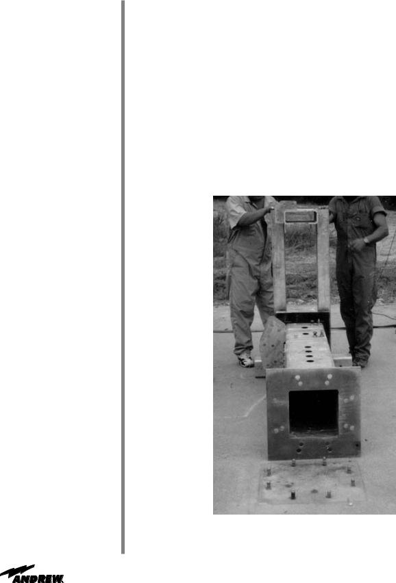
The pedestal ground mount assembly arrives in a packaged wooden crate as shown in Figure 3-2 below. The mount can be positioned manually or by using a crane; however, Andrew recommends that this procedure be performed using a crane to ensure speed and ease of installation.
Figure 3-2: Crate Unpacking
As stated previously, the pedestal ground mount installation process can be conducted manually or by using a crane. The following steps provide the necessary procedures for installing the ground mount assembly using a crane.
16 |
Installation Procedures |

Step 1
Step 2
Step 3
Step 4
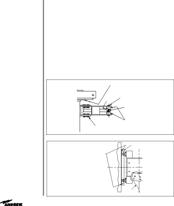
Carefully remove the ground mount assembly (P/N 208800 - motorizable or P/N 202680-2 manual) from the packing crate. Leave the steel strapping intact to avoid disengagement of the panning frame from the square-tube weldment during the ground mount installation.
Securely attach the crane to the ground mount assembly using a sling, and carefully raise the entire ground mount as shown in Figure 3-3.
Figure 3-3: Raising Ground Mount Assembly
Align the ground mount assembly directly over the anchor bolts (P/N 203314 - manual or P/N 203666 - motorizable), which should have been previously mounted in the foundation pad.
NOTE: Ground mount positioning on the foundation is dependent upon predetermined azimuth viewing requirements. The ground mount assembly arm should be positioned opposite the satellite requirement. If your site is in the Northern hemisphere, your satellite will be located in the South. If your site is in the Southern hemisphere, your satellite will be located in the North.
Lower the ground mount assembly onto the anchor bolts with the corresponding hole pattern.
17 |
Installation Procedures |
Step 5
Step 6
Step 7
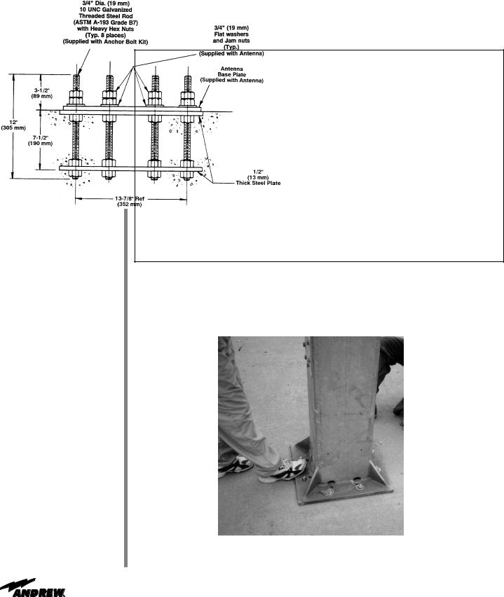
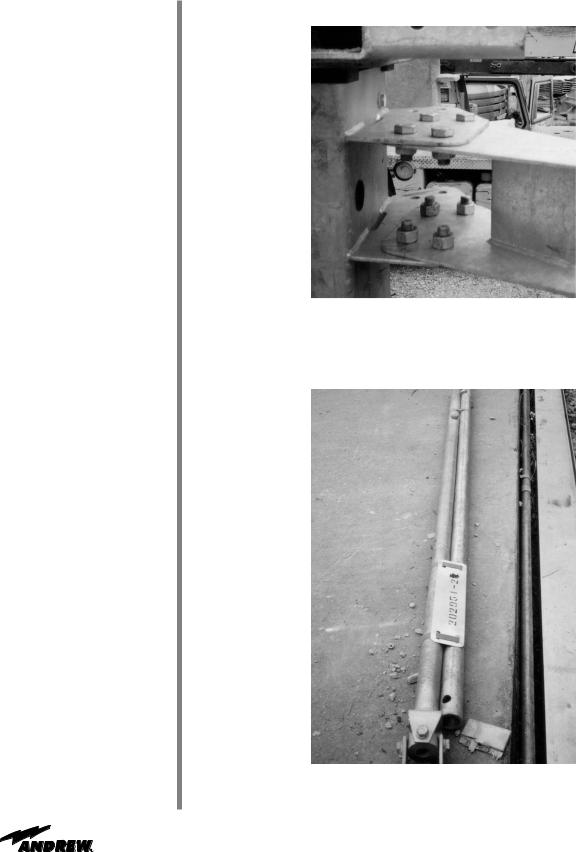
Attach the ground mount assembly to the eight corresponding anchor bolts using a 3/4 inch flat washer and 2-3/4 inch hex nuts as shown in Figure 3-4a. One 3/4 inch hex nut is supplied with the anchor bolt kit and the second 3/4 inch hex nut is supplied with the antenna.
Figure 3-4a: Ground Mount Assembly Base Hardware
Remove the steel strapping from the ground mount assembly.
Tighten the foundation hardware using the A-325 tensioning procedure.
Figure 3-4b shows the ground mount assembly attached to the foundation.
Figure 3-4b: Ground Mount Assembly Base Hardware
18 |
Installation Procedures |
Assembly
(Without a Crane)
Step 1
Step 2
As stated earlier, Andrew recommends the use of a crane during this installation process; however, we recognize that a crane may not always be available. If a crane is not available, the following steps provide the procedure for installing the ground mount assembly without a crane.
Carefully remove the ground mount assembly (P/N 208800-motorizable or P/N 202680- 2- manual) from the packing crate. Leave the steel strapping intact to avoid disengagement of the panning frame from the square-tube weldment during the ground mount installation.
Lay the ground mount assembly on its side, in line with the anchor bolts (P/N 203314manual or P/N 203666-motorizable) as shown in Figure 3-5.
NOTE: Ground mount positioning on the foundation is dependent upon predetermined azimuth viewing requirements. The ground mount assembly panning-frame arm should be opposite of the satellite requirement. If your site is in the Northern hemisphere, your satellite will be located in the South. If your site is in the Southern hemisphere, your satellite will be located in the North.
Figure 3-5: Ground Mount Assembly Alignment with Anchor Bolts
19 |
Installation Procedures |
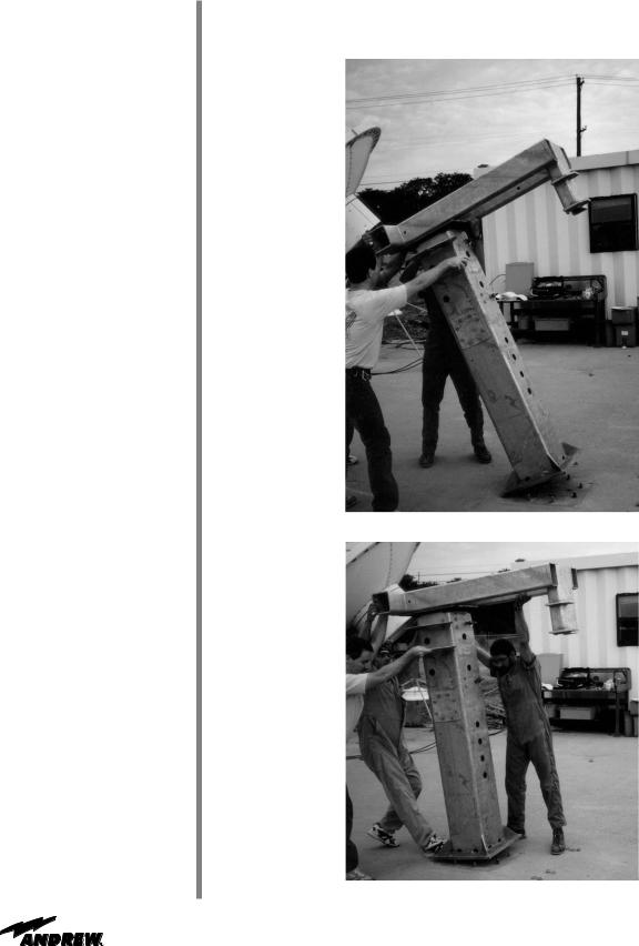
Step 3 Lift the ground mount assembly into an upright position. In the absence of a crane, it is recommended that a minimum of two people assist in the lifting of the mount assembly as shown in Figure 3-6a and Figure 3-6b.
Figure 3-6a: Manual Lift
Figure 3-6b: Manual Lift
20 |
Installation Procedures |
Step 4
Step 5
Step 6
Figure 3-7: Mount Alignment/Adjustment
NOTE: You may need to adjust the mount when lifting it to ensure that the anchor bolts are aligned directly underneath the base of the ground mount assembly as shown in Figure 3-7.
Attach the ground mount assembly to the eight corresponding anchor bolts using a 3/4 inch flat washer and 2-3/4 inch hex nuts as shown in Figure 3-3a.
NOTE: Ground mount positioning on the foundation is dependent upon predetermined azimuth viewing requirements. The ground mount assembly arm should be opposite the satellite requirement. If your site is in the Northern hemisphere, your satellite will be located in the South. If your site is in the Southern hemisphere, your satellite will be located in the North.
Remove the steel strapping from the ground mount assembly.
Tighten the foundation hardware using the A-325 tensioning procedure.
Figure 3-8a illustrates the ground mount assembly attached to the foundation.
Figure 3-8a: Ground Mount Assembly Base Hardware
21 |
Installation Procedures |
Motorizable
Pedestal Ground
Mount Assembly
Step 1
Step 2
Step 3
Step 4
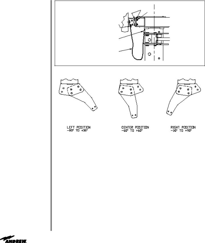
The ground mount assembly enables 180° positioning for selected azimuth viewing. Azimuth range coverage is ±90° divided into three 120° continuous ranges with 30° overlap. Elevation adjustment is continuous from 0 to 90°.
Position and mount 204737 azimuth tiller arm weldment to ground mount assembly as shown using 0.75 x 1.75 in. A-325 bolts and nuts. Tighten hardware per A-325 tensioning procedure. NOTE: Mounting position of azimuth tiller arm weldment is dependent upon predetermined azimuth range requirements as shown.
Apply supplied stick lubricant to set screw threads. Loosely install 0.50 x 1.0 in. set screws in azimuth and 0.50 x 1.50 in. set screws in elevation strut supports.
Position and mount 204754 elevation support angle assembly to ground mount as shown using 0.50 x 1.75 in. A-325 bolts, flat washers and nuts. Tighten hardware per A- 325 tensioning procedure.
Loosely install supplied 0.75 x 2.00 in. A-325 bolts, flat washers and nuts in elevation support angle assembly. This hardware along with the upper elevation strut hardware will be attached to the antenna and tightened to the A-325 tensioning procedure at the time of antenna installation.
Support Plate
1/2 x 1” Bolt and
3/4” Flat Flat Washer
Washer
3/4” Threaded
Rod
Pivot Block
3/4 x 1-3/4”
Bolt and Nut
Figure 3-8b: Ground Mount Assembly Tiller Arm Hardware
EL SPT Angle
Assembly
3/4 x 2” Bolt and Flat Washer
(2 Washers per Bolt, one each on Reflector and Mount Side)
AZ Tiller Arm
Weldment
Figure 3-8c: Ground Mount Assembly Elevation Support Angle
22 |
Installation Procedures |
1/2” Flat |
|
|
|
1/2 x 1-3/4” |
|
Washer |
|
|
|
Bolt and Nut |
|
|
|
|
|
|
|
Universal Terminal
5/16 x 3/4” Hex Head
Screw and Lock Washer
Grounding
Cable
Figure 3-8d: Ground Mount Assembly Tiller Arm Hardware
|
|
|
|
|
|
|
|
Left Position |
|
|
|
Right Position |
|
|
|
Center Position |
|
|||
|
-90° To +30° |
|
-60° To +60° |
|
-30° To +90° |
|
|
|
|
|
|
|
|
|
|
|
|
|
|
|
|
|
|
|
|
|
|
Figure 3-8e: Ground Mount Assembly Tiller Arm Hardware
23 |
Installation Procedures |
Manual Pedestal
Ground Mount
Assembly
Step 1
Step 2
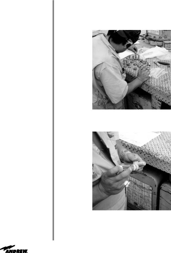
Prepare the ground mount hardware in the mount hardware kit by sorting all bolts, nuts, and flat washers into separate sections as shown in Figure 3-9.
Figure 3-9: Hardware Separation
Wax two sides of each galvanized bolt with the stick wax provided. This allows a smooth installation of each galvanized bolt as shown in Figure 3-10.
Figure 3-10: Waxing Bolts
24 |
Installation Procedures |
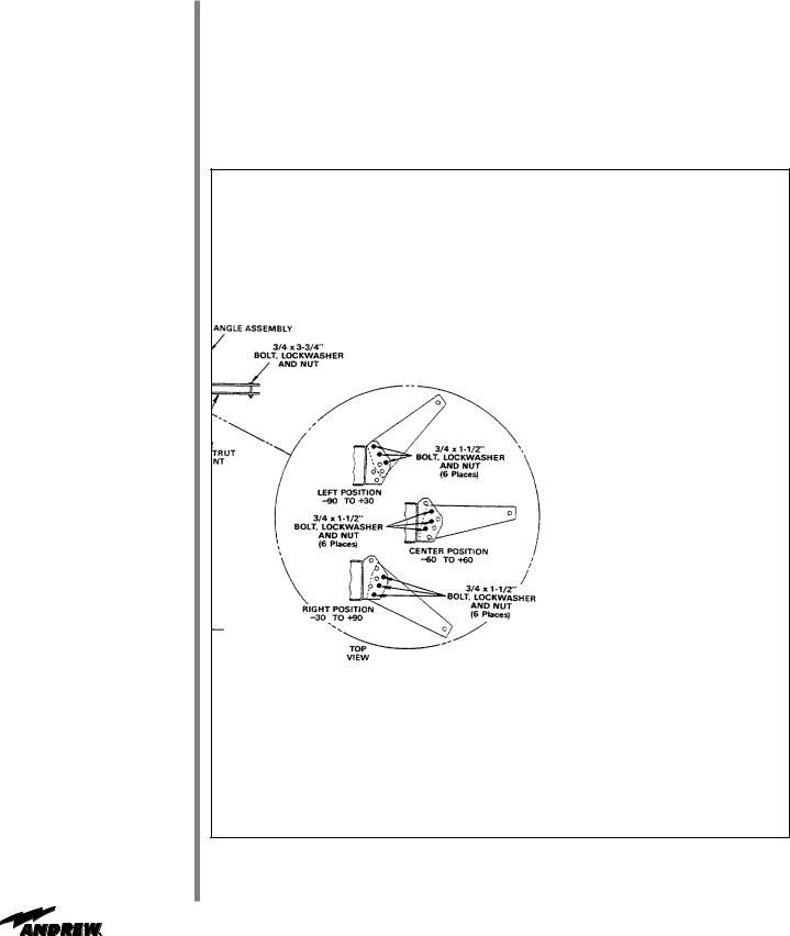
Step 3 Position and mount the azimuth tiller arm (P/N 203112) to the tiller-arm bracket on the left side (facing the satellite) of the ground mount assembly. This mounting position of the azimuth tiller arm is dependent upon pre-determined azimuth range requirements as shown in Figure 3-11.
NOTE: The ground mount assembly enables 180 degrees positioning for selected azimuth viewing. Azimuth range coverage is plus or minus 90 degrees, divided into three 120 degree continuous ranges with a 30 degrees overlap. Elevation adjustment is continuous from 0 degrees to 90 degrees.
Figure 3-11: Azimuth Tiller Arm
Step 4 Tighten the hardware using the A-325 tensioning procedure.
25 |
Installation Procedures |
An illustration of the final azimuth tiller arm is shown in Figure 3-12.
Figure 3-12: Azimuth Tiller Arm - Final Assembly
Step 5 Locate the elevation and azimuth struts (P/N 202951-2-manual) as shown in Figure 3-13.
NOTE: The azimuth strut is the strut on the right and the elevation strut is on the left.
Figure 3-13: Elevation and Azimuth Struts
26 |
Installation Procedures |
 Loading...