


ATC200-Lite Teletilt®
Remote Control Variable Electrical
Downtilt System
Installation and Operation
User Guide
Andrew Corporation
Base Station Antennas
2601 Telecom Parkway
Richardson, Texas 75082-3521 Tel: (214) 631-0310
Fax: (214) 631-4706 www.andrew.com
Bulletin 639510 • May 2005
NOTICE
The installation, maintenance, or removal of an antenna requires qualified, experienced personnel. Andrew installation instructions are written for such installation personnel. Antenna systems should be inspected once a year by qualified personnel to verify proper installation, maintenance, and condition of equipment.
Andrew disclaims any liability or responsibility for the results of improper or unsafe installation practices.
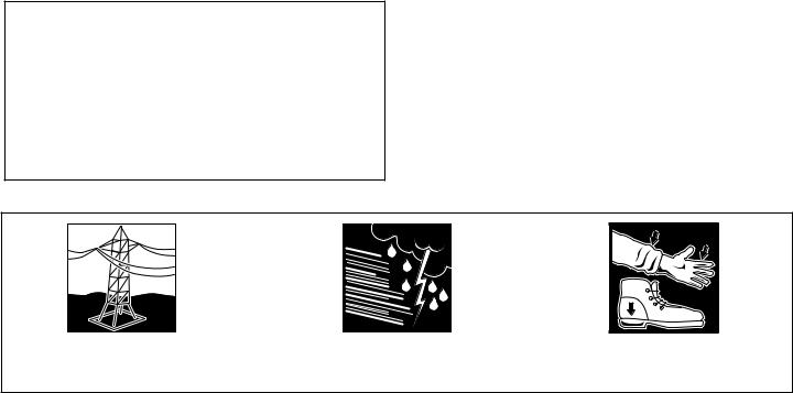
Do not install near power lines. Power lines, telephone lines, and guy wires look the same. Assume any wire or line can
Do not install on a wet or windy day or when lightning or thunder is in the area. Do not use metal ladder.
Wear shoes with rubber soles and heels. Wear protective clothing including a longsleeved shirt and rubber gloves.

Revision History
Revision No. |
Date |
Description of Changes |
|
|
|
None |
May 2005 |
Released. |
|
|
|
Bulletin 639510 |
May 2005 |
i |
ATC200-Lite Teletilt® Remote Control Downtilt System
ii |
May 2005 |
Bulletin 639510 |
ATC200-Lite Teletilt® Remote Control Downtilt System
Bulletin 639510 |
May 2005 |
iii |
ATC200-Lite Teletilt® Remote Control Downtilt System
WARNING
It is very important to disconnect the ATC200-Lite controller from the system after each use to prevent permanent damage to the system.
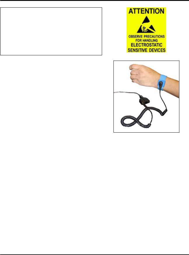
Electric Static Discharge (ESD) can damage or destroy the hardware equipment used for the
ATC200-Lite Teletilt® System. ESD can occur during handling of equipment without the user feeling a shock. The following precautions should be taken to prevent ESD.
1.Wear an ESD wrist strap (Figure 1) and/or use a test lead (ground), such as a single-wire conductor with a series resistance of 1 megohm equipped with alligator clips on each end. In using a ground, one end of the alligator clip is connected to a grounded equipment frame and the other end of the alligator clip is touched with
a bare hand. |
Figure 1. ESD Wrist Strap. |
|
2.Other precautions the user may take to reduce the risk of ESD are:
•avoid wearing clothing that conducts a lot of static electricity, such as wool.
•remove all jewelry.
•avoid handling equipment during an electrical storm.
3.Before opening a package containing an electrostatic unit or an electrostatic sensitive device/assembly, clip the free end of a test lead to the package. Leave the other end connected to the equipment frame or other ESD ground. This will cause any static electricity which may have built up on the package to discharge. Keep the unit package grounded during removal or placement of equipment in the package.
4.Minimize handling of ESDS (Electric Static Discharge Sensitive) equipment. Keep replacement equipment in the electrostatic-free packaging (with ground established between packaging and equipment frame) until needed. Repairable ESD equipment should be placed in the electrostatic-free packaging (with ground connecting package to equipment frame) upon removal from ATC200-Lite system. ESD equipment should only be transported and stored in ESD protective packaging.
iv |
May 2005 |
Bulletin 639510 |

ATC200-Lite Teletilt® Remote Control Downtilt System
5.Always avoid unnecessary movement of body, such as scuffing feet across flooring, when handling ESDS equipment. Such movement will generate additional charges of static electricity.
6.When removing or replacing ESDS equipment, hold the device or assembly through the electrostatic-free wrap, where possible. If this is not possible, lift the device or assembly by its body only. Do not touch component leads, connector pins, or any other electrical connections or paths, even though they are covered by conformal coating.
7.Do not allow ESDS equipment to come in contact with clothing or other ungrounded materials that may have an electrostatic charge. Charges on nonconductive material are not equal. For instance, a plastic storage bag may have a - 10,000 volt potential 1/2 inch from a +15,000 volt potential with many such charges all over the bag. Do not hand ESD equipment to another person until it is safely packaged for protection for ESD.
8.When moving ESDS equipment, always touch the surface on which it rests with bare skin for at least one second before lifting. Before setting it on any surface, touch the surface with your free hand for at least one second. Contact with the bare skin provides a safe discharge path for charges accumulated while you are moving around.
9.While servicing equipment containing ESD devices, do not handle or touch materials such as plastic, vinyl, synthetic textiles, polished wood, fiberglass, or similar items that can generate static charges; unless you repeat the grounding process with the bare hands after contacting these materials.
10.Where possible, avoid repairs that require soldering at the equipment level. Soldering irons must have heater/tips assemblies that are grounded to an electrical ground. Do not use standard plastic solder suckers (special antistatic solder suckers are commercially available).
11.Ground the leads of test equipment momentarily before you energize the test equipment and before you probe ESD devices or assemblies.
12.Work benches used for setting ESDS equipment should have ESD protective work surfaces. These work benches should also have personnel ground straps. These straps prevent discharge of static electricity from personnel handling ESDS items on the work bench surface. The work bench surface should be connected to ground through a ground cable. The resistance in the bench top ground cable should be located at or near the point of contact with the top of the work bench. The resistance should be high enough to limit any leakage current to 5 milliamperes or less. This takes into consideration the highest voltage source within reach of grounded people and all the parallel resistances to ground, such as wrist ground straps, table tops, and conductive flooring.
Bulletin 639510 |
May 2005 |
v |

ATC200-Lite Teletilt® Remote Control Downtilt System
This page intentionally left blank.
vi |
May 2005 |
Bulletin 639510 |

Table
of Contents
Revision History..................................................................................................... |
i |
||
Letter of Compliance............................................................................................. |
ii |
||
Declaration of Conformity.................................................................................... |
iii |
||
Important Notice and Electric Static Discharge Precautions................................. |
iv |
||
Section 1 |
Controller Setup................................................................................ |
1-1 |
|
1.1 |
System Description...................................................................................................... |
1-1 |
|
1.2 |
ATC200-Lite Series Controller Communication............................................................ |
1-1 |
|
1.3 |
ATC200-Lite Series Controller Setup........................................................................... |
1-1 |
|
Section 2 |
Program Installation........................................................................... |
2-1 |
|
2.1 |
Program Download and Installation............................................................................. |
2-1 |
|
2.2 |
Software Upgrades and Antenna Definition File Updates............................................ |
2-3 |
|
Section 3 |
Program Startup and Configuration................................................... |
3-1 |
|
3.1 |
Preparing for Program Startup ................................................................................... |
3-1 |
|
3.2 |
Serial Port Selection at Program Startup.................................................................... |
3-2 |
|
3.3 |
Beginning Program Operation.................................................................................... |
3-4 |
|
3.4 |
Antenna Definitions File Selection.............................................................................. |
3-4 |
|
Section 4 |
Device Discovery and Addressing...................................................... |
4-1 |
|
4.1 |
Device Search............................................................................................................. |
4-1 |
|
4.2 |
Addressing.................................................................................................................. |
4-4 |
|
Section 5 |
Device Configuration......................................................................... |
5-1 |
|
Section 6 |
Changing the Electrical Downtilt on a Single Antenna...................... |
6-1 |
|
Section 7 |
Changing the Electrical Downtilt on a Group of Antennas................ |
7-1 |
|
Section 8 |
Saving a Site Report or Site Configurations....................................... |
8-1 |
|
8.1 |
Saving/Viewing a Site Report Formatted to Open in Word......................................... |
8-1 |
|
8.2 |
Saving/Viewing a Site Report Formatted to Open in Excel......................................... |
8-5 |
|
8.3 |
Saving Configurations for Future Use......................................................................... |
8-8 |
|
Bulletin 639510 |
May 2005 |
v |

Table of Contents ATC200-Lite Teletilt® Remote Control Downtilt System
Section 9 Device Test, Alarm Status and Device Information............................ |
9-1 |
|
9.1 |
Obtaining Device Information...................................................................................... |
9-2 |
9.2 |
Retrieving Current Alarm Status................................................................................. |
9-2 |
9.3 |
Clearing All Alarms on a Device.................................................................................. |
9-3 |
9.4 |
Executing a Self Test Movement for a Device............................................................. |
9-3 |
Section 10 Part Numbering Scheme and Ordering Guide................................ |
10-1 |
|
10.1 |
Part Numbering Scheme........................................................................................... |
10-1 |
10.2 |
Ordering Guide......................................................................................................... |
10-2 |
Section 11 Control System Specifications........................................................ |
11-1 |
|
Appendix A Site Configuration Worksheet....................................................... |
A-1 |
|
Appendix B Antennas for ATC200-Lite Series System..................................... |
B-1 |
|
iivi |
May 2005 |
Bulletin 639510 |
Section 1
Controller Setup
1.1 System Description
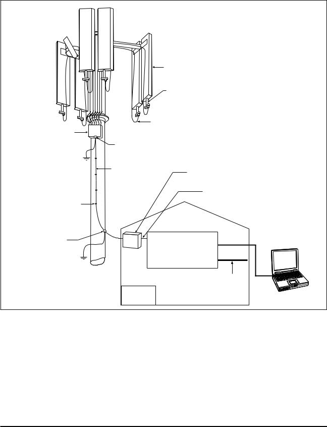
The ATC200-Lite series control system consists of an antenna system controller, actuators attached to the antennas (one for each variable tilt adjuster on an antenna), junction boxes/ splitters to daisy chain up to 32 actuators to a controller, and control cable assemblies. See Section 10 for details on component part numbers and ordering information. Follow the procedures described in the installation bulletins included with each component for successful installation for each device.
It is recommended that each actuator be connected to the controller while on the ground and tested for proper function. The serial number for each actuator, the antenna type the actuator will be installed on, and the location the antenna will be positioned at on the tower site should be recorded prior to installation on the tower. This will assist in configuring the controller to manage tilt operations successfully for each actuator.Asite configuration worksheet is provided with this manual to record the antenna/actuator information (see Appendix A).
1.2 ATC200-Lite Series Controller Communication
The ATC200-Lite controller serves as an interface between a local PC/laptop and the ATM200 RET actuator/antenna system. This controller provides signal level conversion from RS-232
(used on a PC) to RS-485 (used in ATM200-001 actuators), as well as power to the ATM200-
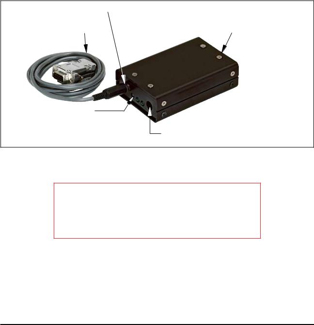
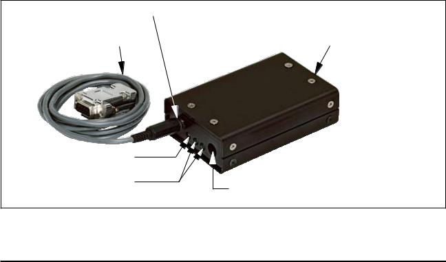
001 actuators that are attached to the antennas. LEDs, on the front panel of the controller, indicate power and data communication. The power LEDs, located nearest to the dc IN port, display green lights when power is supplied to the RET system. The data LED, located nearest to the RS-232 serial port, displays a green light when sending data to the RET system usually followed by an immediate red light when receiving data from the RET system.
1.3 ATC200-Lite Series Controller Setup
1.Connect the supplied 9-Pin RS-232 cable between the controller’s RS-232 serial port and an available RS-232 serial port on the PC or laptop. See Figures 1-1.
Note that the software program used to operate this controller is set at serial port 1 (COM1) as its default. If serial port 1 is unavailable, any functional serial port in the range of
1-8, not currently in use on the PC, is acceptable. A USB to RS-232 serial adapter cable can be used to connect the ATC200-Lite controller to a PC/laptop. Note that after installing the driver for the adapter, it may be necessary to change the ‘Port Mapping’ setting from
‘Geographic’ to ‘Dynamic’ to clear a certain conflict that may occur with the COM port.
Bulletin 639510 |
May 2005 |
1-1 |
Section 1–Controller Setup |
ATC200-Lite Teletilt® Remote Control Downtilt System |
2.Connect the supplied 24Vdc or 12Vdc power converter to the dc IN port on the controller (Figure 1-1). IMPORTANT NOTE: The power converter used will affect both the 12Vdc and 24Vdc connector pins. For example, if a 24Vdc power converter is used, both the 12Vdc and the 24Vdc connector pins will transmit 24Vdc power.
3.Connect the desired length RET control cable between the controller’s 8-Pin DIN connector
(RS-485 RET port, located on the back panel) and the first component in the RET system.
See Figures 1-1 and 1-2 and Section 10 for a brief description of system components.
RS-232 Serial Port |
|
|
|
RS-485 RET Port |
||
|
|
|||||
RS-232 Serial |
|
|
|
|
|
|
|
|
|||||
Cable, Supplied |
|
|
||||
LEDs on
Front Panel
dc IN Port
Figure 1-1. ATC200-Lite Controller with RS-232 Serial Cable Attached.
IMPORTANT
DISCONNECT THE ATC200-Lite CONTROLLER FROM THE
RET SYSTEM AT THE END OF EACH SESSION TO PREVENT
POSSIBLE DAMAGE TO RET DEVICES.
1- |
May 2005 |
Bulletin 639510 |
ATC200-Lite Teletilt® Remote Control Downtilt System |
Section 1–Controller Setup |
|
|
Antenna |
|
|
|
|
|
Field Installed |
|
|
|
|
|
Actuator |
|
|
|
|
|
ATM200-001 |
|
|
|
|
Cable Assembly |
|
|
||
Junction Box |
ATCB-B01-006 |
Additional Products: |
|||
ATJB200-A01-007 |
Cable Ground |
|
ATS-A01-002 Two-Way Splitter |
||
(Up to 32 antennas |
|
||||
|
ATS-B01-003 Three-Way Splitter |
||||
602299 |
|
||||
can be daisy-chained |
|
|
|
||
|
|
|
|
||
by using multiple |
Cable Assembly |
|
|
|
|
junction boxes.) |
Lightning Protection Unit |
||||
ATCB-B01-060 |
|||||
|
ATLP200-001 |
|
|||
|
|
|
|||
|
|
Cable Assembly |
|
||
Hanger Kit Accessories |
|
ATCB-B01-002 |
|
||
|
|
|
|
||
or Cable Ties (40417) |
|
Equipment |
|
|
|
|
|
Cabin |
|
|
|
Cable Ground |
|
|
|
Local Control Interface |
|
Antenna Control Unit |
RS-232 |
Not Supplied |
|||
602299 |
ATC200-1000-00XX |
|
|
||
|
|
|
|||
|
or ATC200-Lite-00XX |
|
|||
|
|
|
Ethernet |
|
|
Example Cable |
dc |
|
(10 Base T) |
|
|
|
|
|
|||
Lengths Shown |
Power |
|
|
|
|
Figure 1-2. Example of ATC200 System Diagram.
Bulletin 639510 |
May 2005 |
1- |

Section 1–Controller Setup |
ATC200-Lite Teletilt® Remote Control Downtilt System |
This page intentionally left blank.
1- |
May 2005 |
Bulletin 639510 |
Section 2
Program Installation
2.1 Program Download and Installation
1.Download the zip file containing the ATC200-Lite setup file from the Andrew Corporation web site (www.andrew.com). This zip file can be placed in any directory on the PC’s local C:\ drive.
2.Unzip the downloaded file to extract the ATC200-Lite setup file and its supporting installation documentation.
3.Double click on the setup file (eg. ATC200LiteSetup2_0.exe) to begin the installation process. Note that the number shown in the filename, following ‘Setup’ and preceding the file extension, represents the software release version.
During the program installation process, a single antenna definition file and additional support files will self-extract into the same directory with the program file, and a program icon will be placed on the PC’s desktop. The antenna definition file equips the program with a drop down list of antennas compatible with the ATC200-Lite controller (also see
Section 3–Program Startup and Configuration). Tilt parameters for each antenna are included in the antenna definition file to show the tilt range for each and to communicate instructions to the antenna/actuator when tilt adjustments are made from the controller.
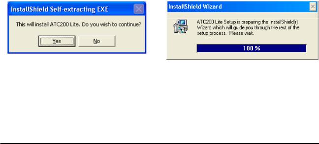
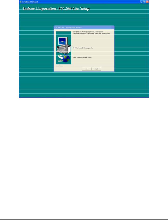
4.Follow the on-screen prompts, as shown in Figures 2-1 through 2-5, to complete the installation.
Figure 2-1. Install Shield Initializes.
Figure 2-2. Install Shield Prepares to Launch
Wizard.
Bulletin 639510 |
May 2005 |
2-1 |

Section 2–Program Installation |
ATC200-Lite Teletilt® Remote Control Downtilt System |
Figure 2-3. Setup Introduction Screen.
Figure 2-4. Installation Settings Screen.
2- |
May 2005 |
Bulletin 639510 |
ATC200-Lite Teletilt® Remote Control Downtilt System |
Section 2–Program Installation |
Figure 2-5. Completing Setup Screen.
2.2 Software Upgrades and Antenna Definition File Updates
Software upgrades containing updated antenna definition files will be available to download from Andrew’s web site. Follow the steps discussed in Section 2.1 to download, unzip, and install ATC200-Lite software upgrades. Note that registered users will receive e-mail notifications alerting them of new software releases. These notifications will include a link to download the upgraded software. New antenna definition files are stored with earlier versions on the PC at ‘C:\Program Files\Andrew Corporation\ATC200 Lite’.
During program startup, the ATC200-Lite controller will look in the directory noted above for the latest Andrew antenna definition file and automatically load it into the program (see Section 3–Program Startup and Configuration).
Bulletin 639510 |
May 2005 |
2- |

Section 2–Program Installation |
ATC200-Lite Teletilt® Remote Control Downtilt System |
This page intentionally left blank.
2- |
May 2005 |
Bulletin 639510 |
Section 3
Program Startup and Configuration
3.1 Preparing for Program Startup
This program is designed to configure and control Andrew’s ATC200-Lite Teletilt®, AISG1 compliant, RET antenna system through a controller connected to a local PC.
1.Verify that the ATC200-Lite controller is turned off/powered down, etc.
2.Verify that the actuator/antenna is properly connected to the ATC200-Lite controller.
3.Verify that the supplied RS-232 cable is connected between the ATC200-Lite controller and an active RS-232 serial port on the PC. Note a USB–to–serial port adapter may be used to connect the ATC200-Lite to the PC (see Section 1.3).
4.Turn on/power up the ATC200-Lite controller. After 2 - 3 seconds, the two power LEDs should display green lights on the front panel of the controller. The power LEDs are located nearest to the dc IN port shown in Figure 3-1.
5.When these two green lights are displayed, start the ATC200-Lite application installed in Section 2. DO NOT start the ATC200-Lite application until the power LEDs display two green lights.
RS-232 Serial Port |
|
|
|
RS-485 RET Port |
||
|
|
|||||
RS-232 Serial |
|
|
|
|
|
|
|
|
|||||
Cable, Supplied |
|
|
||||
Transmit/Recieve Signal
LED
Power LEDs
dc IN Port
Figure 3-1. ATC200-Lite Controller with RS-232 Serial Cable Attached.
Bulletin 639510 |
May 2005 |
3-1 |
Section 3–Program Startup and Configuration ATC200-Lite Teletilt® Remote Control Downtilt System
3.2 Serial Port Selection at Program Startup
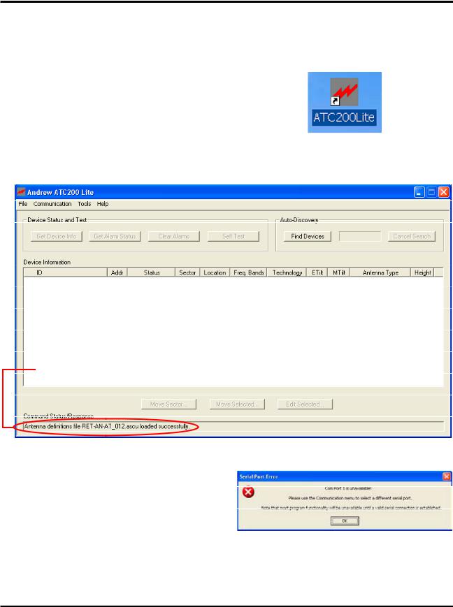
1. The install process places an icon for the program on the desktop (Figure 3-2).
2. Double click on the icon, shown in |
|
|
Figure 3-2, to start the program. If the |
|
|
PC is connected to the controller on |
|
|
serial port 1, and if serial port 1 has |
|
|
been made available to the program |
|
|
by the PC, the program will select |
|
|
that port by default. A successful |
Figure 3-2. ATC200-Lite Application Icon. |
|
connection will display the program’s |
||
|
||
main screen (Figure 3-3). |
|
Command Status/Response window displays program activity.
Figure 3-3. ATC200-Lite Main Screen.
3.If Serial Port 1 does not exist on the
PC, or if the PC is not allowing serial port 1 to be accessed by the program, the program will prompt the user to select a different serial port (Figure
3-4).
Figure 3-4. Prompt for Serial Port Selection.
3- |
May 2005 |
Bulletin 639510 |
 Loading...