

Page 1
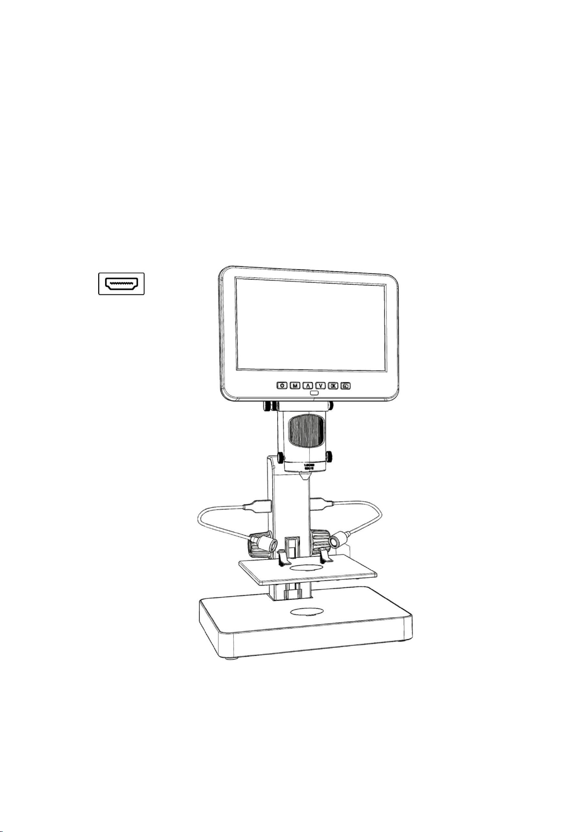
Digital Microscope 246S、249S
Users Manual
(plastic stand)
Page 2

CONTENTS
Safety and maintenance................................................................................................................................................ 1
Specifications .................................................................................................................................................................... 1
Package include ................................................................................................................................................................2
Video demonstration ...................................................................................................................................................... 2
Button&Connection ........................................................................................................................................................3
Bracket installation .......................................................................................................................................................... 3
Bracket instructions .........................................................................................................................................................4
Quick Start......................................................................................................................................................................... 4
How to choose lens .................................................................................................................................................5
Digital zoom ..............................................................................................................................................................8
Save files to micro SD card................................................................................................................................... 8
Remote........................................................................................................................................................................9
Settings ............................................................................................................................................................................. 10
Output to external devices ..........................................................................................................................................12
◆HDMI output .........................................................................................................................................................12
◆USB Output ........................................................................................................................................................... 12
Warranty........................................................................................................................................................................... 18
Page 3
1
Safety and maintenance
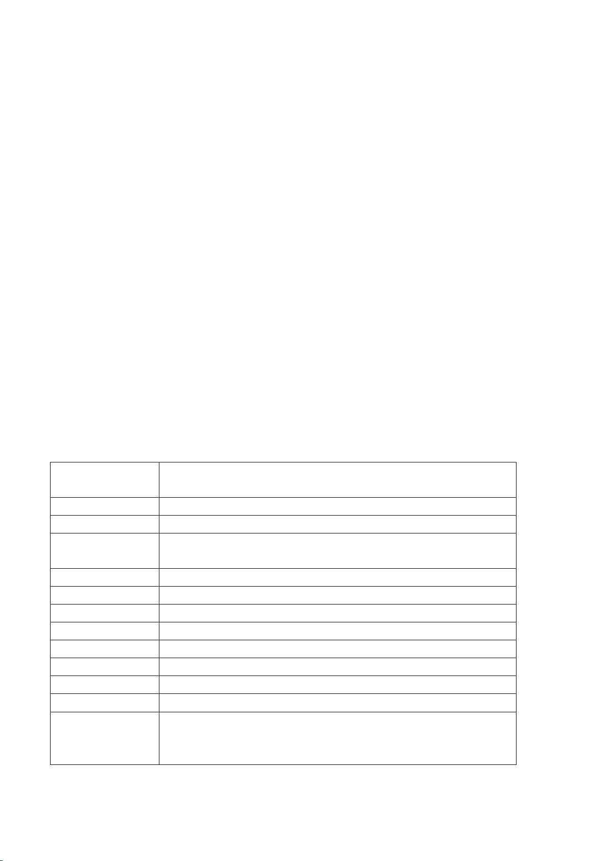
Video resolution
UHD 2880x2160 24fps; FHD 1920x1080 60fps/30fps ;
HD 1280x720 120fps
Video Format
MP4
Frame rate
Max 120fps (600 Lus illumination &HDP120)
Magnification ratio
Lens A: 18-720x; Lens B: 1560-2040x; Lens C: 2760-4080x
(with3 times digital zoom, output to 28inch HDMI monitor)
Focus range
Lens A: 12mm-320mm; Lens B: 7mm-8mm; Lens C: 3mm-4mm
Photo resolution
Max 5600*4200 (24M 5600*4200)
Photo Format
JPG
Storage
Micro-SD card, up to 32G (not included)
Video-output
HDMI
PC Support
Windows XP/7/8/10, PC software with measurement (gift)
Power supply
5V 2A and above
Stand size
20cm*19cm*30cm
Package include
Microscope, Metal stand, 3 Lenses(A,B&C), Remote, Dimmer cable,
HDMI cable, USB cable, Slides kit, Tweezers, Bug box, USB LED
lights*2, Backdrop board*3
1. Please read this users manual carefully before using the device. It may cause permanent damage to the
device to not follow the operation guide listed in this manual.
2. This product contains tiny parts and components that are NOT edible. Please let children and teens use this
device under proper guide and supervise by adults.Disables, patients and people with allergy should not use
this product.
3. We do not recommend using this product outdoor. It is not waterproof, and can not be placed in extreme
environment: heat, high pressure etc.. Please keep and use it in safe, clean and dry environment. Stay it away
from oil, gas, water and corrosive potions. Storage method refers to other electronic products, such as a
computer.
4. Clean the lens when image goes blurry: cut the power supply firstly, wipe the lens with a soft clean cloth
moistened with alcohol, make sure the whole device is dry before power it on again. Users should follow
these steps for daily cleaning as well, remember to ONLY wipe the INSULATED part of the monitor.
5. The screen of the monitor is very fragile, please use it with care. Do not drop, hard press or leave it with
sharp object. Hold the frame of the monitor to adjust its orientation. The monitor is not waterproof, please
clean it with soft and dry material.
6. Please be aware that this microscope is not for medical use.
Specifications
Page 4
2
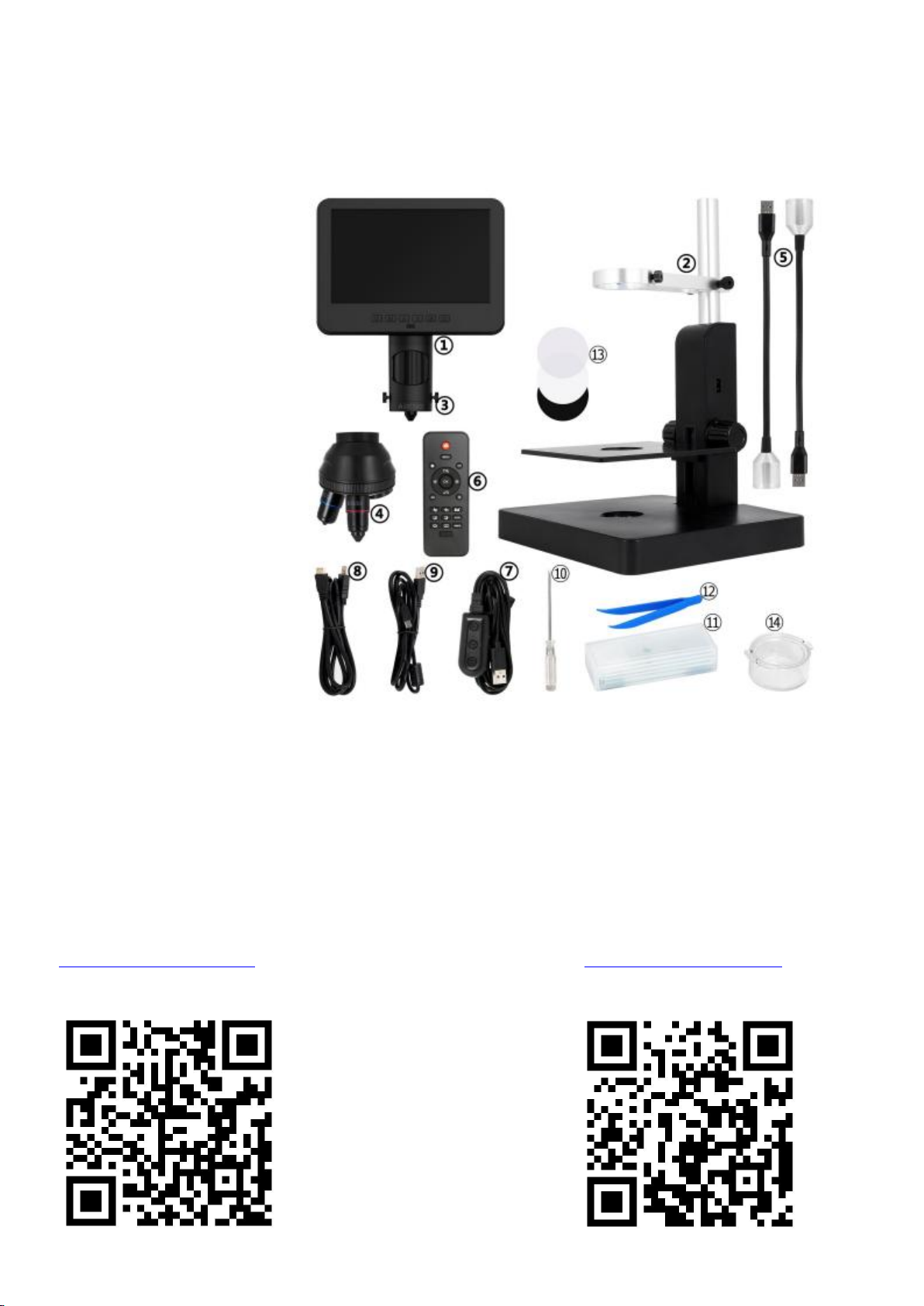
Package include
①Microscope
②Plastic Stand
③Lens A(has been fixed)
④Lens B&C
⑤USB spot lights*2
⑥Remote
⑦Dimmer cable
⑧HDMI cable
⑨USB cable
⑩Screw driver
⑪Slides kit
⑫
Tweezers
⑬Backdrop board*3
⑭Bug box
(P1 Package include)
Video demonstration:
Please find the video demo from the link(Please type all letters properly capitalized)/QR code below,
①Product installation: ②How to choose different lens:
https://bit.ly/377KDSc https://bit.ly/3DwPfgY
Page 5
3
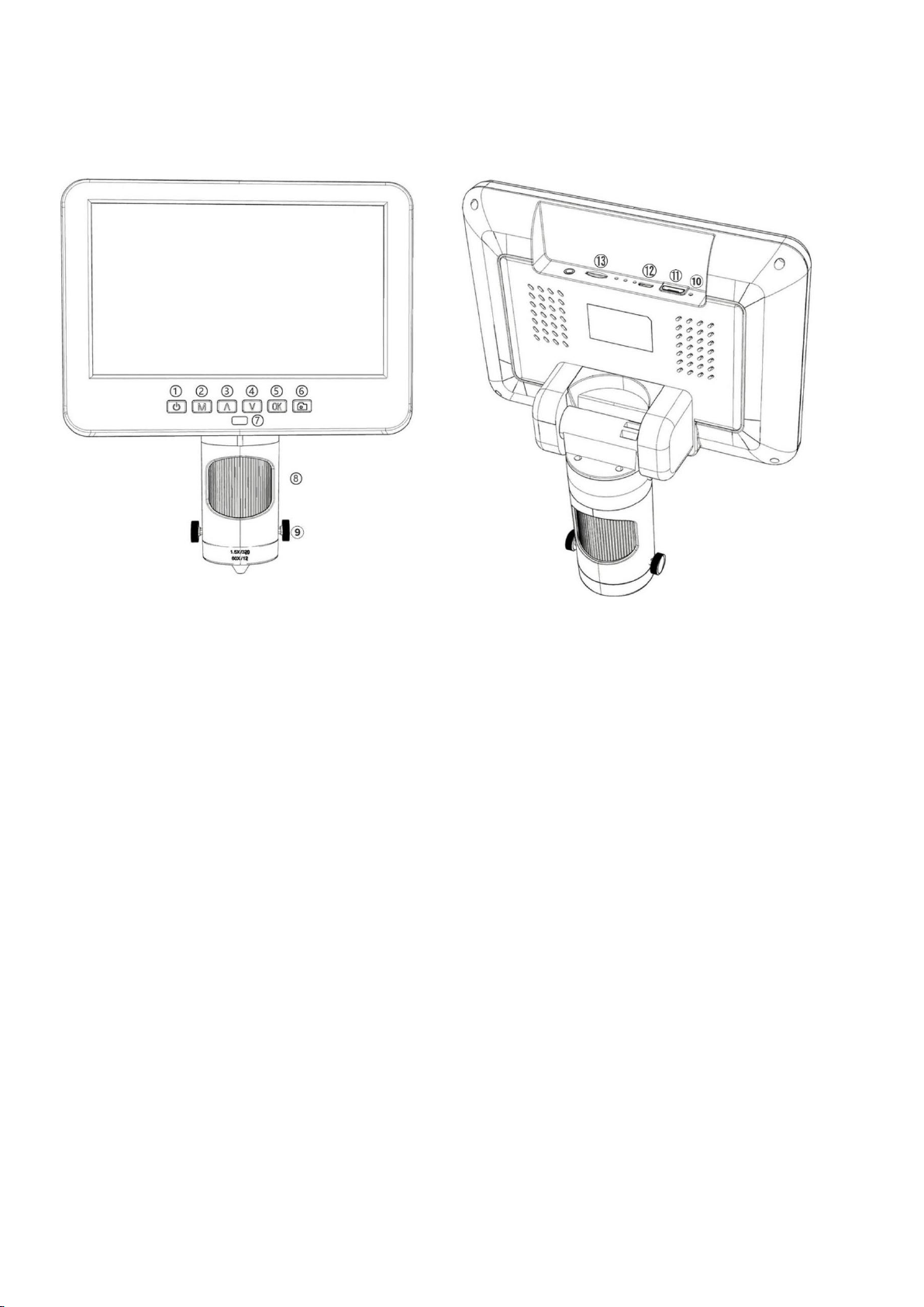
Button&Connection
①Power on/off
②Mode/Menu
③Up/Digital zoom in
④Down/Digital zoom out
⑤OK/Start recording
⑥Take pictures
(while the device is recording)
⑦Remote signal receiver
(where you aim remote to)
⑧Focusing tube
⑨Lens fixing screws
⑩Reset
⑪
HDMI port
⑫USB port
⑬SD card slot
(P2 Buttons&Connection)
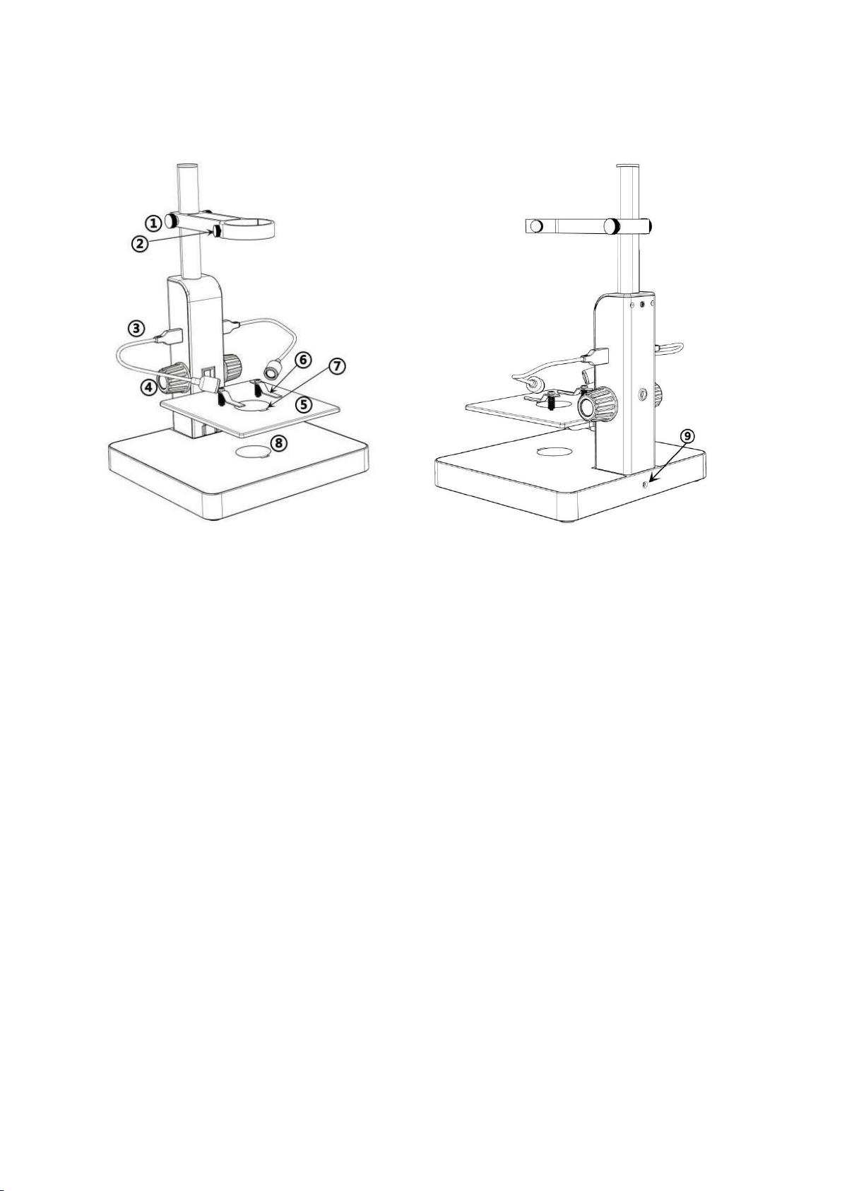
Bracket installation
Please see the attached installation diagram.
Page 6
4
Bracket instructions
①Arm locker
②Monitor Fixing Screws
③USB spot lights
④Stage height controller
⑤Mechanical stage
⑥Clips
⑦Loophole
⑧Bottom light
⑨light socket
(P3 Bracket instructions)
Quick Start
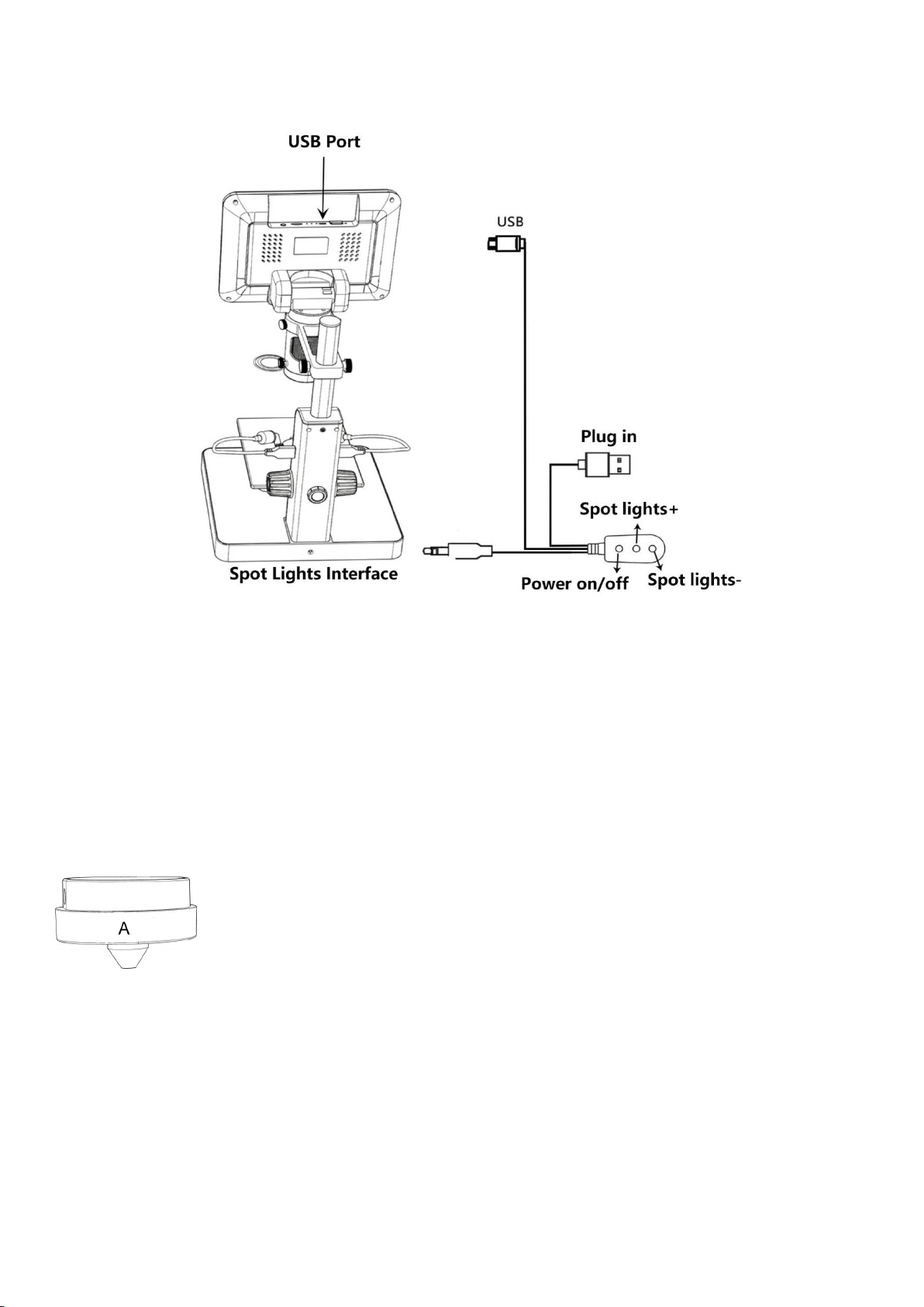
1. Connect the device to power supply as followed pic 4 to power on the microscope.
2. Press and hold the Power button (pic 2 # ① ) until the monitor lights up. (device may switch on
automatically when you power it on, and its totally normal)
*Trouble shooting
When the monitor image stops or froze, please pin the Reset hole (pic 2 #⑩) to reset the device first,
then power on the device again. (Reset hole is very tiny, located at the back of the monitor. You may
need to use the help of other tools with this process. All settings of the microscope will be back to
factory setting after this, but it won’t delete any files saved in memory card).
Page 7
5
(Pic 4 Connection)
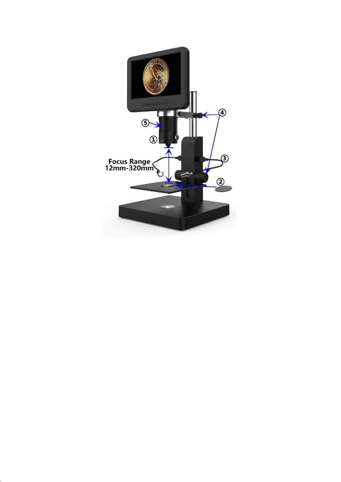
Focus range:12mm-320mm,Magnification:60-240x(with3 times digital zoom,
output to 28inch HDMI monitor)
Applications:observe whole size or part of coins, stones/stamps collect, circuit
board observe etc.
How to choose lens
Lens A:
Page 8
6
(Pic 5 Use lens A to see a coin)
Steps:In pic 5 it marked out which parts of the microscope are involved to each step.
①Install and fix lens A to the bottom of the focusing tube.
②Place the black or white backdrop board to the loophole on the stage, then place the coin on the
stage.
③Bend the two goose-neck spot lights, make sure the light shines on the coin.
④Loose the arm locker, located the whole monitor part to a desire height, meanwhile adjust the height
of the mechanical stage, make sure the final object distance is within 12mm to 320 mm. The shorter the
object distance is, the bigger magnification is.
⑤Turn the focusing tube to get a clear image. Turn it clockwise to zoom in and the other way to zoom
out.
*In order to observe part of the coin, please lower the arm height to shorten the object distance, then
turn the focusing tube, get a clear image.
*Steps above can also be applied to observe plants, stones etc.
Page 9
7
Lens B&C:
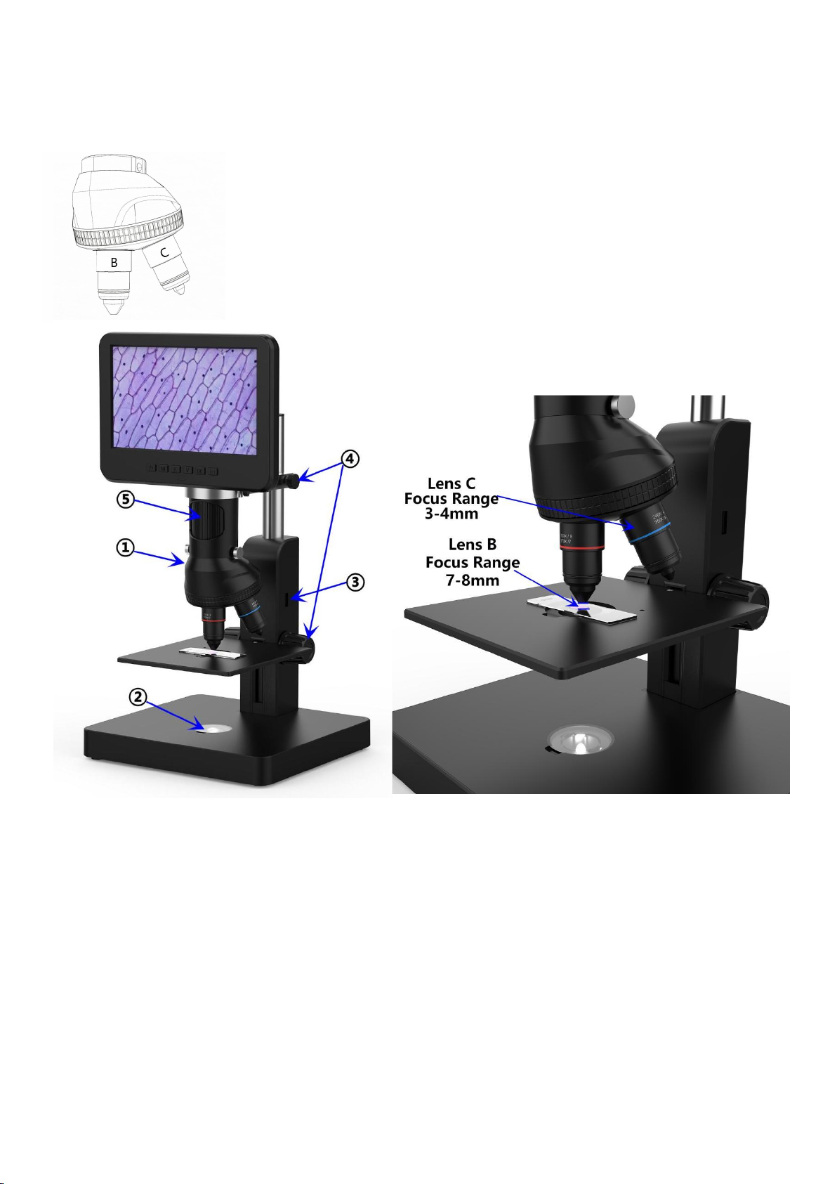
Lens B: Focus range: 7mm-8mm,Magnification: 1560-2040x (with3 times
digital zoom, output to 28 inch HDMI monitor)
Lens C: Focus range: 3mm-4mm,Magnification: 2760-4080x (with3 times
digital zoom, output to 28 inch HDMI monitor)
Applications: Microscope slides etc.
(Pic 6 go with Lens B&C)
Steps:In pic 6 it marked out which parts of the microscope are involved to each step.
①Install and fix the nosepiece set with Lens B&C to the bottom of the focusing tube.
②Place the translucent backdrop board to the loophole on the stage, and place slides on it.
③Remove the two USB spot lights.
④Loose the arm locker, located the whole monitor part to a desire height, meanwhile adjust the height
of the mechanical stage, make sure the final object distance is within 7-8mm(lens B). The shorter the
object distance is, the bigger magnification is. Or if you want to zoom in even more, revolve the
nosepiece to lens C and make the object distance within 3-4mm. The shorter the object distance is, the
bigger magnification is.
⑤Turn the focusing tube to get a clear image. Turn it clockwise to zoom in and the other way to zoom
Page 10
8
out. Or, we recommend users to gently adjust the stage height to get a clear image, this way causes
less shake.
*Lens B&C’s magnification is quite big, which requires a short object distance. Meanwhile, any
tiny movement or shake of specimen would be displayed as huge on the monitor, which requires
user to operate very carefully and patiently.
Digital zoom
Press “up” button on the monitor (pic 2 #③) to apply digital zoom in, and “down” to zoom out( pic
2#④)
Save files to micro SD card
To save images and videos to a memory card, please insert a card into the TF slot at the back of the
monitor before power on the device.
Attention:
1. TD card are not included in the standard package. Please purchase it from quality suppliers. We
recommend 10 grade high speed TF card.
2. Metal strip side of the card faces outward.
3. Push the card deeply into the card slot until you hear a click sound. Otherwise it would bounce back.
4. When the monitor shows “card error” or “card is full”, please format the card first before
take pics. Format steps are: Press and hold button “M” until it shows a menu →press “M”
button again to get into Setting menu→Press up or down button to select→choose”Format” and
confirm
5. Do not insert a card while microscope is working. If you do, the microscope would switch off
automatically. And you will have to turn it on again.
In order to take videos, pictures, or playback files we have taken, we need to get into different modes
firstly. MODE button(pic 4 #②,marked as“M”)can be used to selected among three modes, video( ),
photo( ) and playback( ).
Record videos
In video mode( ) and photo mode( ) press “OK” button to start recording. Press it again to
stop.
It works the same way with the “OK” button on the remote.
In video mode, on the right upper corner of the monitor shows time and “1080FHD”(white font).
Time here shows how long a video the memory card is capable to record, and “1080FHD” shows the
current video resolution.
Page 11
9
Take photos
In video mode( ), photo mode( ) and while the microscope is recording, press capture button( )
to take photos
The button marked as a camera on remote(pic 2 #⑥) works the same way.
* In playback mode the microscope can not take photos or videos
Playback & manage files
Use button “M” to get into Playback mode, press “up” or “down” to browse files.
In order to play videos, press “OK” to play it, “OK” to pause, “M” to stop.
Remote
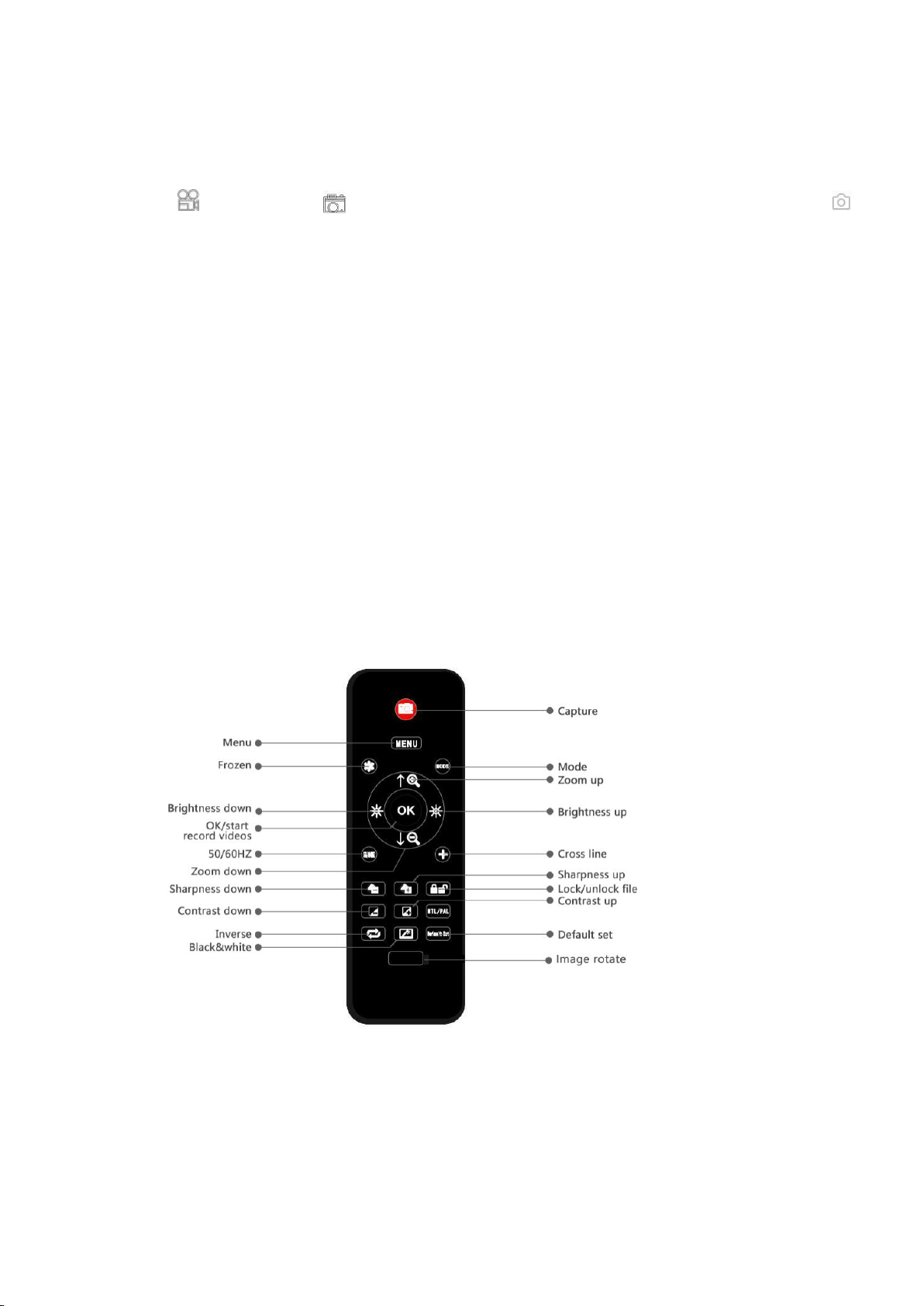
*Freeze: Stop the image on the display, works in video mode, photo mode and while recording.
*Illumination+ & -: exposure compensation from +2.0 to -2.0.
*Sharpness up&down: three levels of sharpness: Soft/Normal/Strong. Those two buttons are both used
to switch the levels, but in different orders.
*Contrast up&down: same principle as Sharpness
(Pic 7 Remote)
Page 12
10
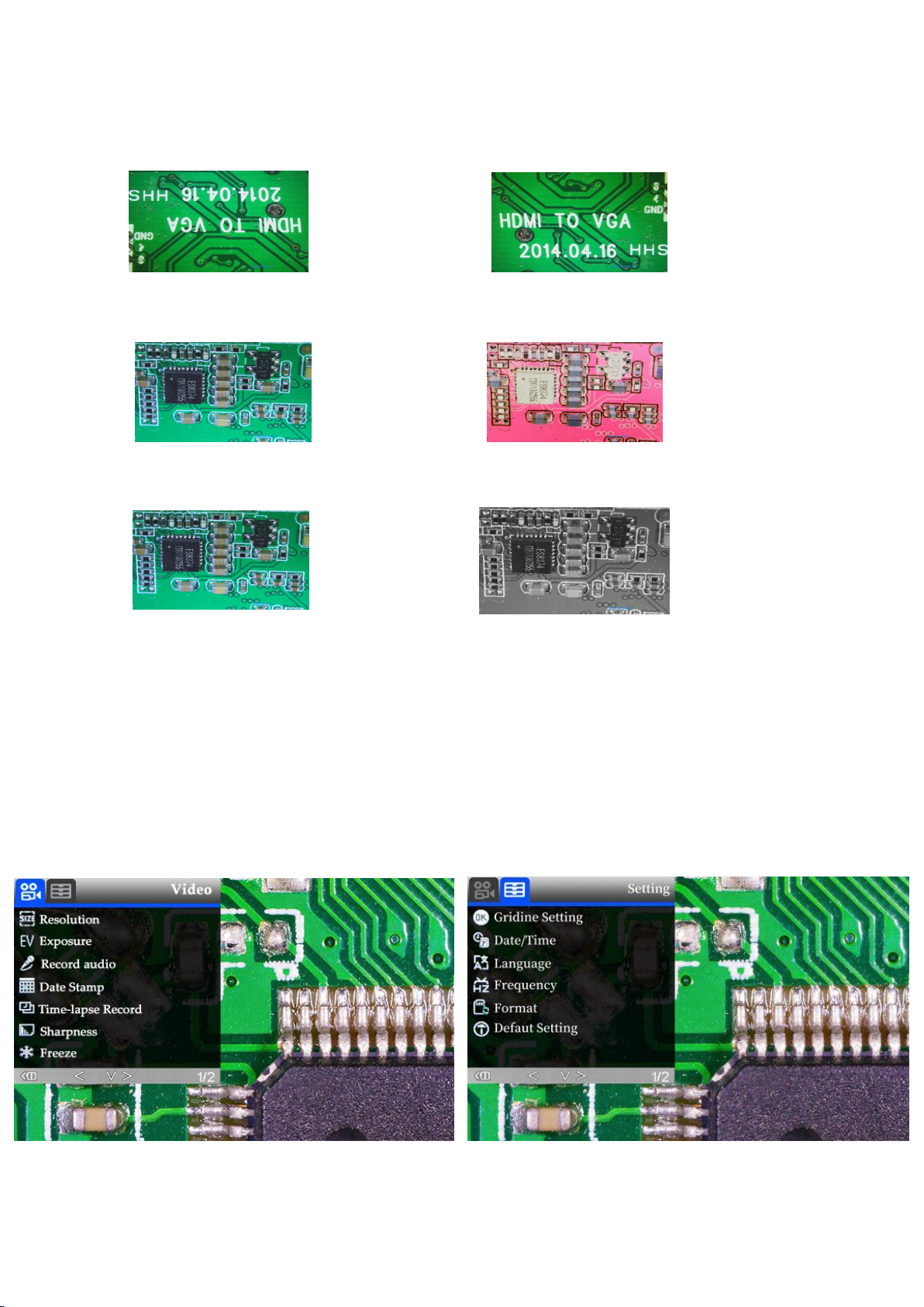
*Upside down:refer to pic as follow
Normal Upside down
*Inverse: refer to pic as follow
Normal Inverse
*Black&white: refer to pic as follow
Normal Black&white
Settings
In any mode, press and hold M button until it shows video/photo/playback menu, press M again, get
into Setting menu.
For example. In video mode, press and hold M button, it would show video menu as left below:
And then, press M again to get into settings menu,as right below:
(pic 8 video menu) (pic 9 setting menu)
Page 13
11
Gridline Settings (remote needed)
Use “Up” and “Down”to choose among “Cross Line” “Line” “Direction” “Location”
“Color”and “Wide”. Use “Left”and “Right”(marked as a brightness +&- in pic 8) to change
settings. The microscope can’t do this mission stand along, The remote is needed.
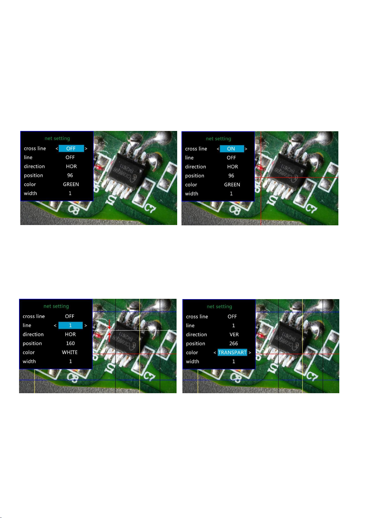
Cross line as its name says, it’s a pair of vertical and horizontal lines located in the very middle in the
image.
(Pic 10 Gridline Setting menu) (Pic 11 Cross line on)
When you turn on the function“Line”, there will be 8 lines showing up automatically(named as 1 to 8).
For each one, you could change its direction (“HOR”or“VER”, stand for “horizontal” and “vertical”),
position, color and width.
To delete unnecessary line from the view, change its color to “TRANSPARENT”see the following pic.
(Pic 13 Delete line 1, before & after)
Page 14

12
Date/Time Setting
Select “Date/Time” in setting menu, press OK button to get in time setting. Use “up”and “down”
button to select correct number, OK to confirm and jump to the next one. After it’s all done, press M to
back to setting menu.
Save Setting
In order to let the microscope memorize the setting changes, please turn off the microscope by
PRESSING THE POWER BUTTON ON THE MONITOR (press and hold until it switch off).
Setting changes won’t be saved if you switch off the device in other ways.
Output to external devices
◆HDMI output
•firstly, make sure the external device is actual real FHD 1080P HDMI monitor, otherwise the display
resolution can not reach to 1080P.
•Power on the microscope, and connect it to the HDMI monitor. The microscope has no built-in battery,
so please make sure the microscope stays powered on the whole time.
• Switch on the microscope, place the specimen on the base or the slide holder, adjust the object
distance and focus distance.
•When the microscope is connect to external devices, image data would transfer to the external device,
so the microscope monitor display no image.
•HDMI output supports photo capture, but not video recording.
◆USB Output
Software installation
Where to download the software:
https://bit.ly/3xCRDPL
Currently software“Microscope Measure”only supports Windows system.
System requires: Windows XP SP3、 Windows 7、Windows8、Windows10
Runtime:Microsoft.Net Framework 4.0
Microsoft Visual C++ 2010
If there isn’t complete either of the runtime mentions above in your computer system, it would report
wrong during the installation process.
If you couldn’t open the download link above, contact our customer service.
After done downloading, open the zip file and run it.
Page 15
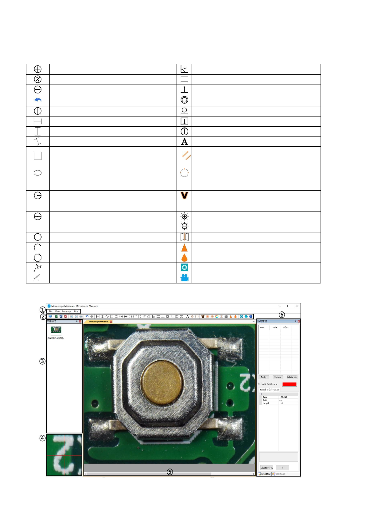
13
*Icons definitions
Zoom In
Measuring a 3-points-angle (degree)
Back to original size
Distance between parallel lines(Length)
Zoom out
Distance from a point to a line (Length)
Undoes the last action
Distance between 2 circles (Radius, length)
Cross hairs (crosier,4 grid, 8 grid)
Distance from a line to a circle(Radius, length)
Horizontal distance of 2 points
Add a square mark
Vertical distance of 2 points
Add a circle mark
distance of 2 points
Add text
Measure a rectangular (width,height,
circumference&area)
Distance between 2 lines(Length)
Measure an ellipse(Long-axis radius,
short-axis radius, circumference&area)
3 points circle (radius, circumference&area)
Measure a radius circle(radius,
circumference&area)
Edge detection
Measure a diameter circle (diameter,
circumference&area)
Brightness increase/decrease
Measure a 3 points circle(radius,
Flip horizontal
Measure a 3 points arc
Sharpen
Measure a polygon (circumference&area)
Smooth
Measure fold-lines (length)
Take a picture
Measure a 4 points angle (degree)
Take a video
*Interface Definitions and Functions
Page 16
14
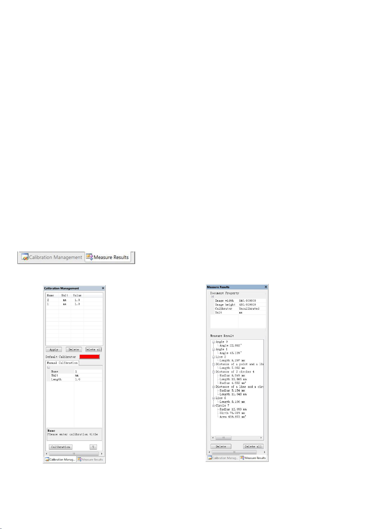
①Main menu:
→Shows the list of different → Shows the size of the
Calibrations. Users can choose whole view. Users Can
to apply or delete. change it in 'File→
Videosetting→Video
capture pin→(S)’.
→Where to set new → Shows all results of
Calibrators. (The details of how measuring.
to set calibrator would be
given in another chapter)
Where users to open different devices or import pictures to observe or edit, do video settings or save
settings, choose which windows to show or hide etc.
②toolbar:
Where show tools that are used to do measuring and image analysis. Definition and function of different
tools has been given in chapter “Icons definitions”. Users can choose to hide or show this toolbar
window following path: 'View→Toolbars and Docking Windows→Standard’.
③Pictures browser:
Where users review all pictures they’ve captured. Users can also edit the picture by right-clicking the
picture and open it in the main operating window. Choose 'View→Toolbars and Docking
Windows→Picture browser' to show or hide this window.
④Secondary operating window:
This window is to digital zoom in the area around cursor. With help of this window, the result of
measuring can be much more precisely.
⑤Main operating window:
This windows shows the full view from the microscope. And it is also the place where users do measuring
and image analysis.
⑥Calibration Management and Measuring Results:
These two windows shows at the same place, users can switch them by clicking.
◆Calibration Management ◆Measure Results
Page 17
15
*Operating Steps
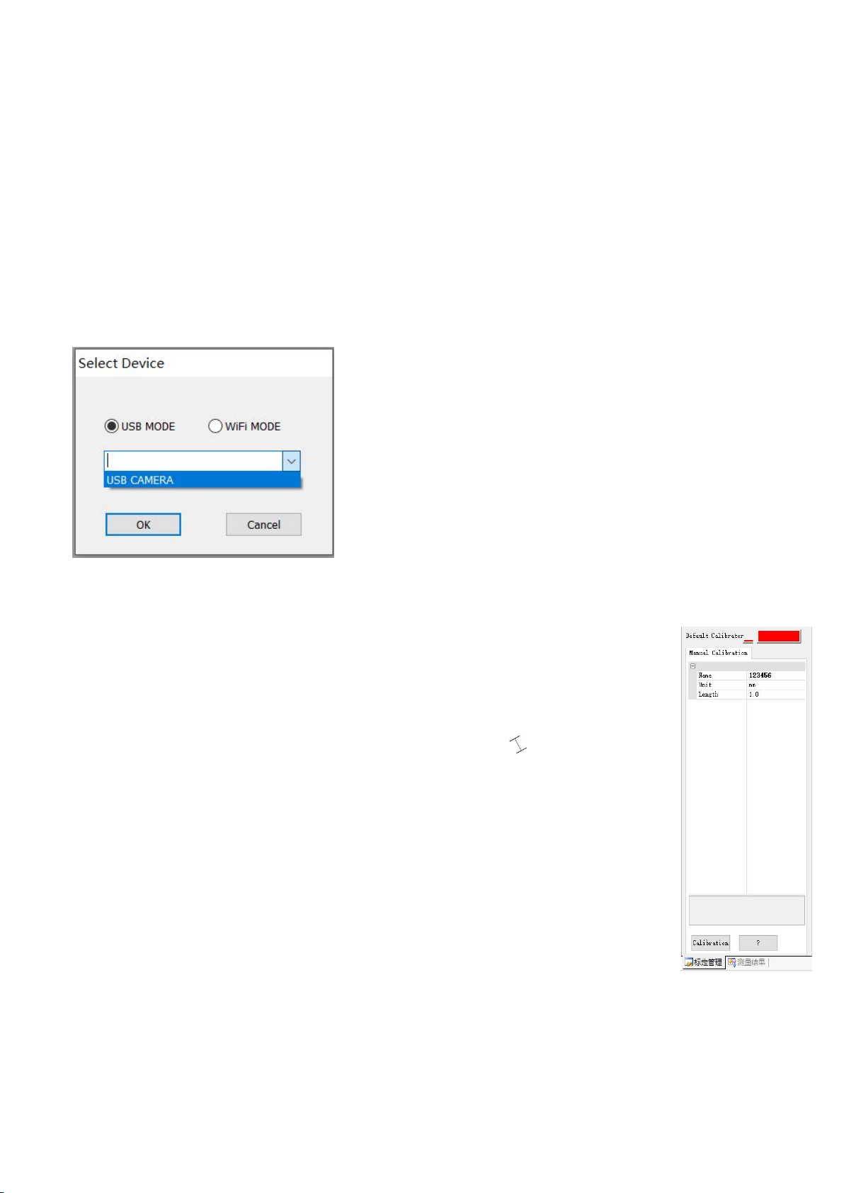
1)Material: A computer (Windows system, with software 'Microscope Measure’); USB microscope (device
name: 'USB CAMERA’), A ruler.
2)Steps
1,Connect the microscope to computer via the USB cable included. After the microscope monitor
displays few options, choose “USB camera”by pressing button “down”&”OK” or using remote.
2,Open software“Microscope Measure”.
3,Click “File”→ “Open”→ “Open Device”→ “USB MODE” → “USB CAMERA”.
*Functions
1)Calibration
1, Put the ruler under the digital microscope, adjust the focusing tube and the height of the
stand, to get the best clearance and desired magnification. (After its done, keep the object
distance for the rest steps)
2, In the 'Calibration management' set the name and unit length of the new calibration(refer
the picture on the right). Then, click 'Calibration', meanwhile, the ' ' in the toolbar should
have been chosen automatically. If no, please choose it yourselves.
3, Move the cursor to the main operation window, draw a unit length line with help of the
ruler(it doesn’t matter if the length result shows differently). After these, click the 'Finish'
button in the bottom of the 'Calibration Management' window.
4, Check. The length of the line you draw in step 3 should now appear as the unit length. The
name of the new calibration should have showed in the list of calibrations.
Page 18

16
3)
4)
2) Measuring
1, Choose the tool you need to do measuring in the toolbar.
2, Click dots or draw lines that you need to measure in the main operating window.
3, Place the results of measuring in a proper place around the target.
3) Special Effect
·Includes: Edge detection, Inverse color, Flip horizontal, Relief, Sharpen and Smooth.
·Steps:
1, Choose the special effect you need in the toolbar.。
2, Move your cursor to the main operating window, Left-click and hold to draw a rectangle to cover the whole
target area, release your mouse, get the special effect result.
3, Left click again, end the special effect.
Page 19
17
PS: Not like other special effect, “Flip horizontal” would apply to the whole view, instead of the target
rectangle.
4) Capture and Recording
·Capture
1, Click ' ' to capture.
2, The result of capture can be reviewed and deleted in the 'Picture browser' window.
3, Check and change the save path: “File→Save Setting→Path”.
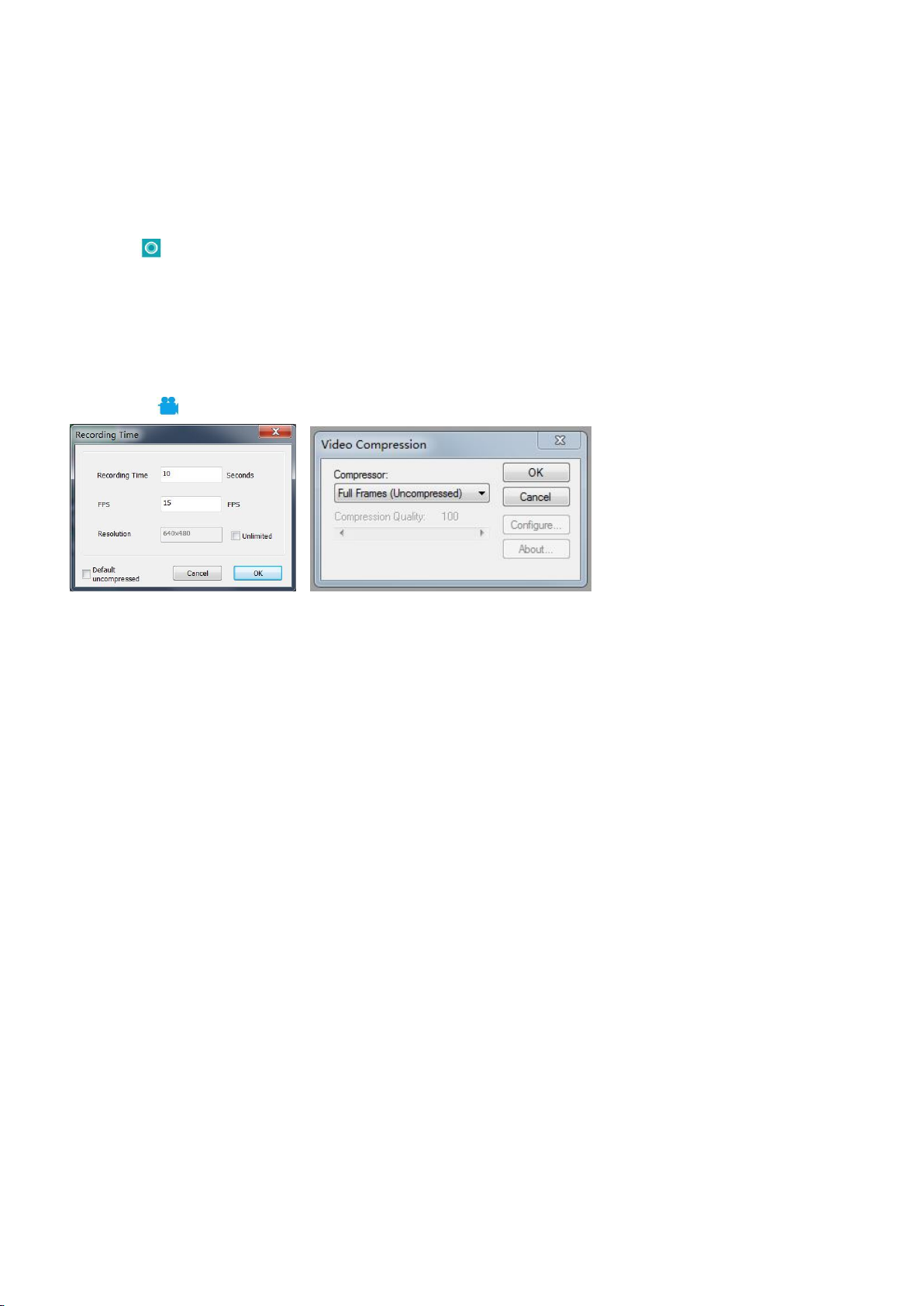
·Recording
1, Choose the video resolution as 640*480 following path “File→Video Setting→Video Capture Pin→Output
size(S)”
2, Click
“ ”,
finish the other settings and start to record.
3, Once it starts to record, it would show a timer on the upper left corner.
4, Check and change the save path: “File→Save Setting→Path”.
FAQ
1. Why it says ‘missing files' during installation or initiator procedure?
Please confirm that in the system there are Microsoft. Net Framework 4.0 and Microsoft Visual C++ 2010
runtime.
2. The software works fine, but the software can not recognize the microscope.
Firstly, please make sure that you have connected the microscope to the PC properly and have chosen ‘USB
camera' on the microscope monitor. Secondly, if there is still no image, please check the ‘Device Manager' of
your PC, delete the previous USB camera from “image devices”, then rescan device changes. Let the system
identifies again. After its done, in the ‘Imaging devices' there should have shown the current USB camera
device name, which is “USB Camera”. Then reboot the software.
3. Why there is a measurement error? In order to get a more precise measure result, you would need a more
precise calibration. And when you apply a calibrator to measure a length, you need to keep the magnification
still, which means you need to keep the object distance still as when you set the calibration.
Why the microscope can’t be switch on?Please connect the microscope properly as pic 4, and make
4.
Page 20
18
sure it has stable and strong 5V 2A power supply. If it doesn’t work, pin the reset hole at the back side of the
Warranty
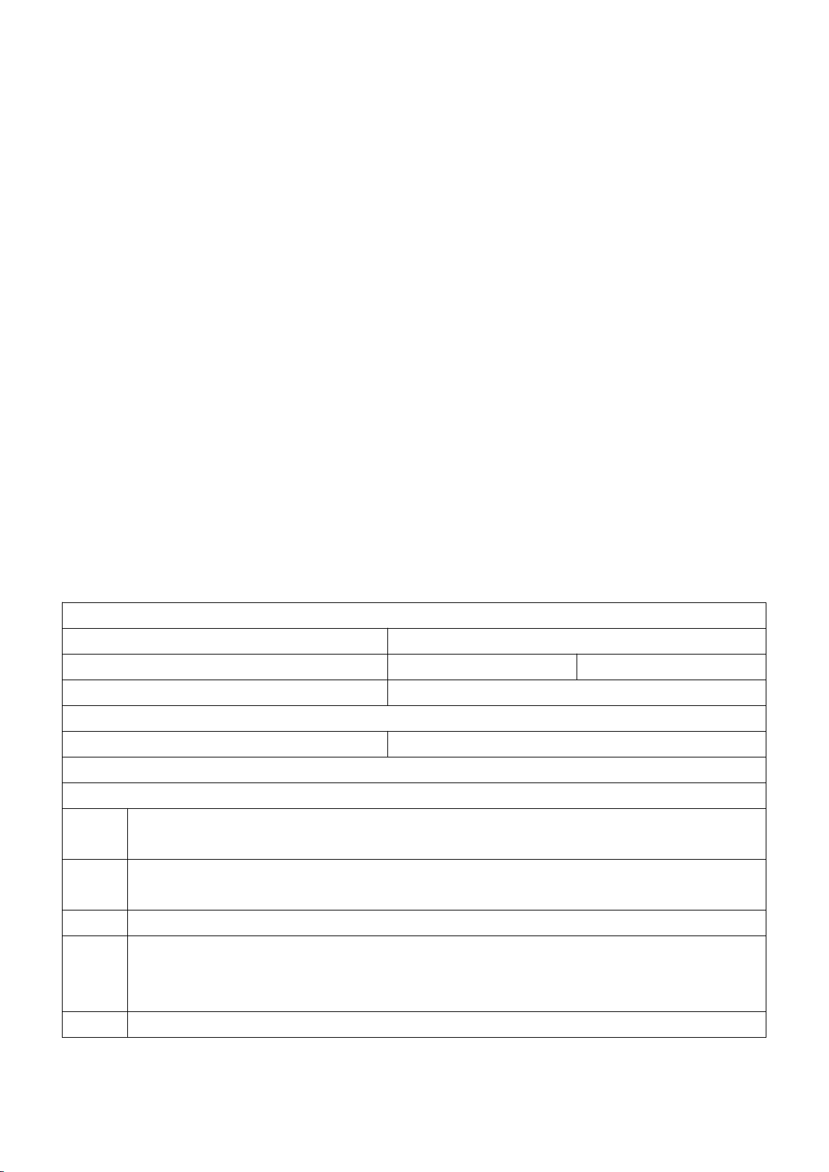
Name:
Address:
Phone number:
Post code:
Email:
Model name:
Purchase date:
Fault details:
Date:
Fault description:
Notice:
Our warranty does not cover:
1
If the purchaser can not provide a purchase proof, or it shows the product was bought as
second hand condition
2
If the product has been placed or used in an improper environment, such as heat, wet,
wrong power supply environment etc.
3
If the fault caused by accident, oversight, faulty operation or natural disasters etc.
4
If the fault caused by people who are not belong to authorized organizations of our
company during repacking, repair, dismantle, Or if users repack, repair or dismantle the
device not following our advice.
5
Out of warranty period.
monitor.
5. Why can’t I get a clear image?Please confirm the illumination work properly, and shine directly to the
surface of the specimen. Adjust the height of the boom arm, or the secondary bracket lift to change the
distance from the lens to the specimen, and turn the focusing tube properly. If the image is still blurry, please
clean the bottom of the lens use a piece of clean and soft cloth.
6. Why the setting changes can’t be memorized? After changing settings, press and hold the button on the
monitor to switch off the device. DO NOT cut off the power supply directly or use the dimmer cable to switch
off the device.
7. Why the microscope reboots repeatedly? Please check the if the cable connection is firm and if the
power supply is stable and strong enough. Please check your power adapter is high quality 5V 2A.
8. Why it shows “card error” or “card is full” after inserting memory card to the device. Please format the
card after insert it into the device.(Format steps refer to chapter “Save files to micro SD card”)
PS:If there are other questions or problems, please contact us as soon as possible, we will do
our best to help! Thanks for your support!
Warranty
 Loading...