

Page 1

W4.5
User’s Guide
Analog Devices, Inc.
One Technology Way
Norwood, Mass. 02062-9106
Revision 2.0, April 2006
Part Number:
82-000420-02
Page 2

Copyright Information
©2006 Analog Devices, Inc., ALL RIGHTS RESERVED. This document
may not be reproduced in any form without prior, express written consent
from Analog Devices, Inc.
Printed in the USA.
Disclaimer
Analog Devices, Inc. reserves the right to change this product without
prior notice. Information furnished by Analog Devices is believed to be
accurate and reliable. However, no responsibility is assumed by Analog
Devices for its use; nor for any infringement of patents or other rights of
third parties which may result from its use. No license is granted by implication or otherwise under the patent rights of Analog Devices, Inc.
Trademark and Service Mark Notice
The Analog Devices logo, the CROSSCORE logo, VisualDSP++,
SHARC, TigerSHARC, Blackfin, and EZ-KIT Lite are registered trademarks of Analog Devices, Inc.
All other brand and product names are trademarks or service marks of
their respective owners.
Page 3

CONTENTS
PREFACE
Purpose of This Manual .............................................................. xxiii
Intended Audience ...................................................................... xxiii
Manual Contents ......................................................................... xxiv
What’s New in This Manual .......................................................... xxv
Technical or Customer Support .................................................... xxvi
Supported Processors ................................................................... xxvii
Product Information .................................................................. xxviii
MyAnalog.com ..................................................................... xxviii
Processor Product Information ................................................ xxix
Related Documents ................................................................ xxix
Online Technical Documentation ............................................ xxx
Accessing Documentation From VisualDSP++ .................... xxxi
Accessing Documentation From Windows .......................... xxxi
Accessing Documentation From the Web ........................... xxxii
Embedded Processing & DSP Knowledge Base .................. xxxii
Printed Manuals ................................................................... xxxiii
VisualDSP++ 4.5 User’s Guide iii
Page 4

VisualDSP++ Documentation Set .................................... xxxiii
Hardware Tools Manuals ................................................. xxxiii
Processor Manuals ........................................................... xxxiii
Data Sheets ..................................................................... xxxiii
Notation Conventions ................................................................ xxxiv
INTRODUCTION TO VISUALDSP++
VisualDSP++ Features .................................................................. 1-2
Integrated Development and Debugging .................................. 1-2
Code Development Tools ........................................................ 1-2
Source File Editing Features .................................................... 1-3
Project Management Features .................................................. 1-4
Debugging Features ................................................................. 1-5
VDK Features ......................................................................... 1-6
VisualDSP++ 4.5 Features ....................................................... 1-7
License Management .................................................................. 1-10
Licensing Options ................................................................. 1-11
License Status ....................................................................... 1-12
Temporary Licenses .......................................................... 1-12
Valid Versus Expired Licenses ............................................ 1-12
Client Licenses ................................................................. 1-12
License Installation ............................................................... 1-13
VisualDSP++ Product Upgrades ............................................ 1-14
Product Serial Numbers ........................................................ 1-14
Project Development .................................................................. 1-15
iv VisualDSP++ 4.5 User’s Guide
Page 5

Overview of Programming With VisualDSP++ ....................... 1-15
Project Development Stages ................................................... 1-17
Targets .................................................................................. 1-19
Simulation Targets ............................................................ 1-19
EZ-KIT Lite Targets ......................................................... 1-20
Emulator Targets ............................................................... 1-20
Platforms .............................................................................. 1-20
Debugging Overview ............................................................. 1-23
VisualDSP++ Kernel .............................................................. 1-25
Program Development Steps .................................................. 1-25
Step 1: Create a Project ..................................................... 1-26
Step 2: Configure Project Options ..................................... 1-26
Step 3: Add and Edit Project Source Files .......................... 1-26
Adding Files to Your Project .......................................... 1-26
Creating Files to Add to Your Project ............................. 1-27
Editing Files .................................................................. 1-27
Managing Project Dependencies .................................... 1-27
Step 4: Specifying Project Build Options ........................... 1-27
Configuration ............................................................... 1-28
Project-Wide File and Tool Options .............................. 1-28
Individual File and Tool Options ................................... 1-28
Step 5: Build a Debug Version of the Project ...................... 1-29
Step 6: Create a Debug Session and Load the Executable .... 1-29
Step 7: Run and Debug the Program ................................. 1-29
VisualDSP++ 4.5 User’s Guide v
Page 6

Step 8: Build a Release Version of the Project .................... 1-29
Code Development Tools ............................................................ 1-30
Compiler .............................................................................. 1-31
C++ Run-Time Libraries ....................................................... 1-32
Dinkum Abridged C++ Library ......................................... 1-32
Assembler ............................................................................. 1-33
Linker ................................................................................... 1-34
Expert Linker ........................................................................ 1-37
Expert Linker Window ..................................................... 1-38
Memory Map Pane Right-Click Menu .............................. 1-39
Stack and Heap Usage ....................................................... 1-42
Archiver ................................................................................ 1-44
Splitter ................................................................................. 1-44
Loader .................................................................................. 1-45
Processor Projects ....................................................................... 1-47
Project Options ..................................................................... 1-48
Project Groups ...................................................................... 1-49
Project Group Files ........................................................... 1-50
Source Code Control (SCC) .................................................. 1-51
Makefiles .............................................................................. 1-52
Rules ................................................................................ 1-53
Output Window ............................................................... 1-54
Example Makefile ............................................................. 1-54
Project Configurations .......................................................... 1-56
vi VisualDSP++ 4.5 User’s Guide
Page 7

Customized Project Configurations ........................................ 1-57
Project Build ......................................................................... 1-57
Build Options ....................................................................... 1-58
File Building ......................................................................... 1-59
Batch Builds .......................................................................... 1-59
Pre-Build and Post-Build Options .......................................... 1-59
Command Syntax .................................................................. 1-60
Project Dependencies ............................................................ 1-60
Project Window Rules ........................................................... 1-60
VisualDSP++ Help System .......................................................... 1-62
ENVIRONMENT
Project Window ............................................................................ 2-2
Project View ............................................................................ 2-3
Project Dependencies .............................................................. 2-3
Project Nodes .......................................................................... 2-4
Project Folders .................................................................... 2-4
Project Files ........................................................................ 2-6
Project Window Icons for Source Code Control (SCC) ........ 2-7
Project Page Right-Click Menus ............................................... 2-8
Project Group Icon Right-Click Menu ................................. 2-8
Project Icon Right-Click Menu ............................................ 2-9
Folder Icon Right-Click Menu .......................................... 2-10
File Icon Right-Click Menu ............................................... 2-10
File Associations .................................................................... 2-11
VisualDSP++ 4.5 User’s Guide vii
Page 8

Automatic File Placement ...................................................... 2-12
File Placement Rules ......................................................... 2-12
Example ........................................................................... 2-13
Kernel Page ........................................................................... 2-13
Editor Windows ......................................................................... 2-13
Editor Window Symbols ....................................................... 2-16
Bookmarks ............................................................................ 2-17
Syntax Coloring .................................................................... 2-17
Viewing Modes: Source Mode vs. Mixed Mode ...................... 2-18
Source Mode .................................................................... 2-18
Mixed Mode ..................................................................... 2-18
Editor Tab Mode .................................................................. 2-19
Context-Sensitive Expression Evaluation ................................ 2-21
Viewing an Expression ...................................................... 2-22
Highlighting an Expression ............................................... 2-22
Right-Click Menu ................................................................. 2-23
Output Window ......................................................................... 2-24
Viewing Error Message Details .............................................. 2-24
Output Window Tabs ........................................................... 2-26
Build Page ........................................................................ 2-26
Console Page .................................................................... 2-26
Code Development Tools Batch Processing Messages ............. 2-27
Message Severity Hierarchy ............................................... 2-28
Syntax of Help for Error Messages ..................................... 2-28
viii VisualDSP++ 4.5 User’s Guide
Page 9

Promoting, Demoting, and Suppressing Error Messages ..... 2-29
Suppressing Compiler Warnings and Remarks ................ 2-33
Log File ................................................................................. 2-34
Output Window Customization ............................................. 2-34
Right-Click Menu ................................................................. 2-35
Script Command Output ....................................................... 2-36
Debugging Windows ................................................................... 2-39
Disassembly Windows ........................................................... 2-40
Other Disassembly Window Features ................................. 2-43
Right-Click Menu ............................................................. 2-43
Disassembly Window Symbols .......................................... 2-45
Expressions Window .............................................................. 2-46
Expressions Permitted in an Expression Window ................ 2-47
Trace Windows ...................................................................... 2-48
Locals Window ...................................................................... 2-50
Statistical/Linear Profiling Window ........................................ 2-51
Window Components ....................................................... 2-51
Left Pane ...................................................................... 2-51
Right Pane .................................................................... 2-53
Status Bar ..................................................................... 2-53
Right-Click Menu ......................................................... 2-53
Window Operations .......................................................... 2-54
Changing the Window View ......................................... 2-54
Displaying a Source File ................................................ 2-55
VisualDSP++ 4.5 User’s Guide ix
Page 10

Displaying Functions in Libraries .................................. 2-55
Working With Ranges ................................................... 2-56
Switching Display Modes .............................................. 2-56
Filtering PC Samples With No Debug Information ....... 2-56
Call Stack Window ............................................................... 2-59
Memory Windows ................................................................ 2-59
Number Formats in Memory Windows ............................. 2-60
Memory Window Right-Click Menu ................................. 2-62
Expression Tracking in a Memory Window ....................... 2-63
Memory Window Display Customization .......................... 2-65
Background Telemetry Channels (BTCs) ............................... 2-65
BTC Definitions in Your Program ..................................... 2-66
Enabling BTC on ADSP-2126x and ADSP-BF36x Processors 2-67
BTC Priority .................................................................... 2-68
BTC Memory Window ..................................................... 2-68
BTC Memory Window Right-Click Menu ........................ 2-70
Register Windows ................................................................. 2-71
Stack Windows ..................................................................... 2-74
Custom Registers Windows ................................................... 2-74
Multiprocessor Window ........................................................ 2-75
Multiprocessor Window Pages ........................................... 2-76
Status Page ................................................................... 2-76
Groups Page ................................................................. 2-77
Operating on Multiprocessor Groups ................................ 2-77
x VisualDSP++ 4.5 User’s Guide
Page 11

Focus ................................................................................ 2-78
Right-Click Menu ............................................................. 2-78
Pipeline Viewer Window ....................................................... 2-79
Right-Click Menu ............................................................. 2-80
Pipeline Viewer Properties Dialog Box ............................... 2-81
Pipeline Viewer Window Event Icons ................................ 2-82
Pipeline Instruction Event Details ..................................... 2-83
Cache Viewer Window .......................................................... 2-84
Configuration Page ........................................................... 2-87
Detailed View Page ........................................................... 2-88
History Page ..................................................................... 2-89
Performance Page .............................................................. 2-91
Histogram Page ................................................................. 2-92
Address View Page ............................................................ 2-93
VDK Status Window ............................................................. 2-94
VDK State History Window .................................................. 2-96
Thread Status and Event Colors ........................................ 2-97
Window Operations .......................................................... 2-98
Right-Click Menu ............................................................. 2-98
Target Load Window ............................................................. 2-99
Plot Windows ..................................................................... 2-100
Plot Window Features ..................................................... 2-101
Status Bar ................................................................... 2-101
Tool Bar ...................................................................... 2-102
VisualDSP++ 4.5 User’s Guide xi
Page 12

Right-Click Menu ...................................................... 2-103
Plot Window Statistics .................................................... 2-105
Plot Configuration ......................................................... 2-106
Plot Window Presentation .............................................. 2-107
Plot Presentation Options ............................................... 2-109
Image Viewer ...................................................................... 2-109
Automation Interface ...................................................... 2-111
Toolbar .......................................................................... 2-111
Status Bar ....................................................................... 2-112
Right-Click Menu .......................................................... 2-112
DEBUGGING
Debug Sessions ............................................................................. 3-2
Debug Session Management .................................................... 3-3
Simulation vs. Emulation ........................................................ 3-3
Breakpoints ........................................................................ 3-3
Watchpoints ....................................................................... 3-4
Multiprocessor (MP) System Debugging .................................. 3-4
Setting Up a Multiprocessor Debug Session ......................... 3-4
Debugging a Multiprocessor System .................................... 3-5
Focus and Pinning .......................................................... 3-6
Window Title Bar Information ........................................ 3-6
Additional Focus Indication ............................................ 3-7
Code Analysis Tools ...................................................................... 3-7
Statistical Profiles and Linear Profiles ....................................... 3-8
xii VisualDSP++ 4.5 User’s Guide
Page 13

Simulation: Linear Profiling ................................................ 3-8
Emulation: Statistical Profiling ............................................ 3-8
Traces ...................................................................................... 3-9
Program Execution Operations .................................................... 3-10
Selecting a New Debug Session at Startup .............................. 3-10
Loading the Executable Program ............................................ 3-11
Program Execution Commands .............................................. 3-11
Restarting the Program .......................................................... 3-12
Performing a Restart During Simulation ............................ 3-12
Performing a Restart During Emulation ............................. 3-13
Breakpoints ........................................................................... 3-13
Unconditional and Conditional Breakpoints .......................... 3-14
Automatic Breakpoints .......................................................... 3-14
Watchpoints .......................................................................... 3-15
Hardware Breakpoints ........................................................... 3-16
Latency ............................................................................. 3-16
Restrictions ....................................................................... 3-16
Simulation Tools ......................................................................... 3-16
Interrupts .............................................................................. 3-17
Input/Output Simulation (Data Streams) ............................... 3-17
Plots ........................................................................................... 3-19
Plot Types ............................................................................. 3-20
Line Plots .............................................................................. 3-21
X-Y Plots ............................................................................... 3-22
VisualDSP++ 4.5 User’s Guide xiii
Page 14

Constellation Plots ................................................................ 3-23
Eye Diagrams ........................................................................ 3-24
Waterfall Plots ...................................................................... 3-25
Spectrogram Plots ................................................................. 3-27
Flash Programmer ....................................................................... 3-28
Flash Devices ........................................................................ 3-29
Flash Programmer Functions ................................................. 3-29
Flash Driver .......................................................................... 3-30
Flash Programmer Window ................................................... 3-30
Energy-Aware Programming ........................................................ 3-31
Ranking ................................................................................ 3-31
Example ............................................................................... 3-31
REFERENCE INFORMATION
Support Information ..................................................................... A-2
IDDE Command-Line Parameters ................................................ A-7
Extensive Scripting ....................................................................... A-8
File Types ................................................................................... A-12
Parts of the User Interface ........................................................... A-15
Title Bar ............................................................................... A-16
Additional Information in Title Bars ................................. A-17
Title Bar Right-Click Menu .............................................. A-17
Control Menu ....................................................................... A-18
Program Icons .................................................................. A-18
Editor Windows ............................................................... A-18
xiv VisualDSP++ 4.5 User’s Guide
Page 15

Debugging Windows ........................................................ A-19
Menu Bar ............................................................................. A-19
Toolbars and User Tools ........................................................ A-19
Built-In Toolbars ............................................................. A-20
Toolbar Customization ..................................................... A-21
User Tools ....................................................................... A-22
Toolbar Buttons ............................................................... A-22
Toolbar Operation ........................................................... A-22
Toolbar Button Appearance .............................................. A-27
Toolbar Shape .................................................................. A-27
Toolbars: Docked vs. Floating .......................................... A-28
Toolbar Rules ................................................................... A-29
Status Bar ............................................................................. A-30
Keyboard Shortcuts .................................................................... A-32
Working With Files .............................................................. A-32
Moving Within a File ........................................................... A-33
Cutting, Copying, Pasting, Moving Text ............................... A-34
Selecting Text Within a File .................................................. A-34
Working With Bookmarks in an Editor Window ................... A-35
Building Projects .................................................................. A-36
Using Keyboard Shortcuts for Program Execution ................. A-36
Working With Breakpoints ................................................... A-37
Obtaining VisualDSP++ Help ............................................... A-37
Miscellaneous ....................................................................... A-37
VisualDSP++ 4.5 User’s Guide xv
Page 16

Window Operations ................................................................... A-39
Window Manipulation .......................................................... A-39
Right-Click Menu Options ................................................... A-40
Scroll Bars and Resize Pull-Tab .............................................. A-40
Windows: Docked vs. Floating .............................................. A-41
Docked Windows ............................................................. A-41
Floating Windows ............................................................ A-43
Window Position Rules ......................................................... A-43
Standard Windows Buttons ................................................... A-45
Text Operations .......................................................................... A-46
Regular Expressions vs. Normal Searches ............................... A-46
Specific Special Characters ................................................ A-47
Special Rules for Sequences ............................................... A-48
Repetition and Combination Characters ........................... A-48
Match Rules ..................................................................... A-49
Tagged Expressions in Replace Operations ............................. A-49
Comment Start and Stop Strings ........................................... A-50
Online Documentation ............................................................... A-51
Printing Online Documentation ............................................ A-52
Viewing Online Help ............................................................ A-53
Online Help ............................................................................... A-54
Help Window ....................................................................... A-54
Context-Sensitive Help ......................................................... A-55
Viewing Menu, Toolbar, or Window Help ......................... A-57
xvi VisualDSP++ 4.5 User’s Guide
Page 17

Viewing Dialog Box Help ................................................. A-57
Viewing Window Help ..................................................... A-58
Copying Example Code From Help ...................................... A-58
Printing Help ....................................................................... A-58
Bookmarking Frequently Used Help Topics ........................... A-59
Navigating in Online Help ................................................... A-60
Searching Help ..................................................................... A-61
Full-Text Searches ............................................................ A-61
Rules for Full-Text Searches .......................................... A-63
Advanced Search Techniques ............................................ A-64
Wildcard Expressions ................................................... A-64
Boolean Operators ....................................................... A-65
Nested Expressions ....................................................... A-66
Rules for Advanced Searches ......................................... A-66
Glossary ..................................................................................... A-67
SIMULATION OF SHARC PROCESSORS
Anomaly Options ......................................................................... B-2
ADSP-21x6x Processor Anomalies ........................................... B-2
Shadow Write FIFO Anomaly (ADSP-2116x Only) ................. B-2
SIMD Read from Internal Memory With Shadow Write FIFO Hit
Anomaly (ADSP-2116x Only) ............................................. B-3
Event Options .............................................................................. B-4
FP Denorm ............................................................................ B-4
Short Word Anomaly .............................................................. B-4
VisualDSP++ 4.5 User’s Guide xvii
Page 18

Access to ADSP-21065L Short-Word Internal Memory 9th Column at
Even Addresses ..................................................................... B-7
Recording a Simulator Anomaly or Event ...................................... B-7
Select Processor ID Options .......................................................... B-9
Simulator Options ...................................................................... B-10
No Boot Mode ...................................................................... B-10
Load Sim Loader Options ........................................................... B-11
SPI Simulation in Slave Mode ..................................................... B-13
SIMULATION OF TIGERSHARC PROCESSORS
ADSP-TS101 Processors ............................................................... C-1
Simulator Timing Analysis Overview ....................................... C-2
Pipeline Stages ........................................................................ C-2
Stalls ....................................................................................... C-3
Stalls Due to IALU Dependency ......................................... C-4
Stalls Due to Compute Block Dependency .......................... C-5
Aborts .................................................................................... C-6
Aborts Due to an Unpredicted Change of Flow ................... C-6
Abort Due to Mispredicted Change of Flow ........................ C-7
Branch Target Buffer Hits ................................................... C-8
Pipeline Viewer and Disassembly Window Operations ............. C-8
Current Program Counter Value ......................................... C-9
Stepping ........................................................................... C-11
Simulator Options ................................................................ C-12
ADSP-TS20x Processors ............................................................. C-13
xviii VisualDSP++ 4.5 User’s Guide
Page 19

Simulator Timing Analysis Overview .................................... C-13
Pipeline Stages ...................................................................... C-14
Stalls .................................................................................... C-15
Stalls Due to IALU Dependency ....................................... C-15
Stalls Due to Compute Block Dependency ........................ C-16
Stalls Due to a Cache Miss ............................................... C-17
Aborts .................................................................................. C-17
Aborts Due to an Unpredicted Change of Flow ................. C-18
Abort Due to Mispredicted Change of Flow ...................... C-19
Branch Target Buffer Hits ................................................ C-20
Pipeline Viewer and Disassembly Window Operations ........... C-20
Current Program Counter Value ....................................... C-21
Stepping .......................................................................... C-23
Simulator Options ........................................................... C-23
SIMULATION OF BLACKFIN PROCESSORS
Peripheral Support in Simulators .................................................. D-2
Special Considerations for Peripherals ........................................... D-7
Universal Asynchronous Receiver/Transmitter Peripheral ......... D-7
Timer (TMR) Peripheral ......................................................... D-7
Simulator Instruction Timing Analysis for ADSP-BF535 Processors D-9
Stall Reasons .......................................................................... D-9
Kill Reasons ......................................................................... D-10
Pipeline Viewer Window Examples ....................................... D-11
Pipeline Viewer Window Messages ........................................ D-12
VisualDSP++ 4.5 User’s Guide xix
Page 20

Pipeline Viewer Detail View Stall Event Messages ............. D-12
Kills Detected Messages ................................................... D-16
Multicycle Instructions .................................................... D-17
Abbreviations in Pipeline Viewer Messages ............................ D-17
Simulator Instruction Timing Analysis for ADSP-BF531, ADSP-BF532,
ADSP-BF533, and ADSP-BF561 Processors ............................ D-19
Stall Reasons ........................................................................ D-19
Kill Reasons ......................................................................... D-20
Pipeline Viewer Window Examples ....................................... D-20
Multicycle Instructions and Latencies ......................................... D-22
Multicycle Instructions ......................................................... D-22
Push Multiple or Pop Multiple ......................................... D-22
32-Bit Multiply (modulo 232) ......................................... D-23
Call and Jump ................................................................. D-23
Conditional Branch ......................................................... D-23
Return ............................................................................. D-24
Core and System Synchronization .................................... D-24
Linkage ........................................................................... D-25
Interrupts and Emulation ................................................ D-25
TESTSET ....................................................................... D-25
Instruction Latencies ............................................................ D-26
Accumulator to Data Register Latencies ........................... D-27
Register Move Latencies ................................................... D-28
Move Conditional and Move CC Latencies ...................... D-30
Loop Setup Latencies ....................................................... D-31
xx VisualDSP++ 4.5 User’s Guide
Page 21

Latencies Due to Instructions Within Hardware Loops ..... D-32
Instruction Alignment Unit Empty Latencies .................... D-33
L1 Data Memory Stalls ......................................................... D-34
Minibank Access Collision ............................................... D-35
SRAM Access (1-Cycle Stall) ........................................ D-35
Cache Access (1-Cycle Stall) ......................................... D-36
Memory-Mapped Register (MMR) Access ........................ D-39
System Minibank Access Collision .................................... D-39
Store Buffer Overflow ...................................................... D-39
Store Buffer Load Collision .............................................. D-40
Load/Store Size Mismatch ............................................ D-40
Store Data Not Ready .................................................. D-41
Instruction Groups ............................................................... D-41
Register Groups .................................................................... D-42
Compiled Simulation ................................................................. D-44
Specifying a Session for Compiled Simulation ....................... D-44
INDEX
VisualDSP++ 4.5 User’s Guide xxi
Page 22

xxii VisualDSP++ 4.5 User’s Guide
Page 23

PREFACE
Thank you for purchasing Analog Devices, Inc. development software for
digital signal processing (DSP) applications.
Purpose of This Manual
The VisualDSP++ 4.5 User’s Guide describes the features, components,
and functions of VisualDSP++. Use this guide as a reference for develop-
ing programs for SHARC®, TigerSHARC®, and Blackfin® processors.
This manual does not include detailed procedures for building and debugging projects. For how-to information, refer to VisualDSP++ online Help
and the VisualDSP++ 4.5 Getting Started Guide.
Intended Audience
The primary audience for this manual is a programmer who is familiar
with Analog Devices processors. This manual assumes that the audience
has a working knowledge of the appropriate processor architecture and
instruction set. Programmers who are unfamiliar with Analog Devices
processors can use this manual, but should supplement it with other texts
(such as the appropriate hardware reference and programming reference
manuals) that describe your target architecture.
VisualDSP++ 4.5 User’s Guide xxiii
Page 24

Manual Contents
Manual Contents
The manual consists of:
• Chapter 1, “Introduction to VisualDSP++”
Describes VisualDSP++ features, license management, project
development, code development tools, VCSE, and DSP projects
• Chapter 2, “Environment”
Focuses on window features, operations, and customization for the
main window and debugging windows.
• Chapter 3, “Debugging”
Describes debug sessions, code analysis tools, program execution
operations, simulation tools, and utilities.
• Appendix A, “Reference Information”
Describes file types, keyboard shortcuts, command-line parameters,
scripting, toolbar buttons, and text operations; also provides a
glossary and describes online Help features and operations.
• Appendix B, “Simulation of SHARC Processors”
Describes the simulator options available on the Anomalies,
Events, Simulator, Load Sim Loader, and Select Processor ID
submenus under Settings; also explains how to record simulator
anomalies and events, and describes SPI simulation in slave mode.
• Appendix C, “Simulation of TigerSHARC Processors”
Describes simulator instruction timing analysis, pipeline stages, the
Pipeline Viewer, stalls, aborts, the current program counter value,
stepping, and the Select Loader Program command on the Simu-
lator submenu under Settings.
• Appendix D, “Simulation of Blackfin Processors”
Provides an overview of peripheral support for Blackfin simulators
and describes limitations of the simulation software models, simulator instruction timing analysis, and compiled simulation.
xxiv VisualDSP++ 4.5 User’s Guide
Page 25

What’s New in This Manual
The VisualDSP++ 4.5 User’s Guide supports all Analog Devices, Inc.
processor families listed in “Supported Processors” on page -xxvii.
Refer to the list of new VisualDSP++ 4.5 user interface features in
“VisualDSP++ 4.5 Features” on page 1-7. Refer to the VisualDSP++ 4.5
Product Release Bulletin for information on new and updated
VisualDSP++ 4.5 features and other release information. Also refer to
VisualDSP++ Help for details.
Preface
VisualDSP++ 4.5 User’s Guide xxv
Page 26

Technical or Customer Support
Technical or Customer Support
You can reach Analog Devices, Inc. Customer Support in the following
ways:
• Visit the Embedded Processing and DSP products Web site at:
http://www.analog.com/processors/technicalSupport
• E-mail tools questions to:
processor.tools.support@analog.com
• E-mail processor questions to:
processor.support@analog.com
• Phone questions to 1-800-ANALOGD
• Contact your Analog Devices, Inc. local sales office or authorized
distributor
• Send questions by mail to:
Analog Devices, Inc.
One Technology Way
P.O. Box 9106
Norwood, MA 02062-9106
USA
xxvi VisualDSP++ 4.5 User’s Guide
Page 27

Preface
Supported Processors
The following is the list of Analog Devices, Inc. processors supported in
VisualDSP++ 4.5.
TigerSHARC (ADSP-TSxxx) Processors
The name “TigerSHARC” refers to a family of floating-point and
fixed-point [8-bit, 16-bit, and 32-bit] processors. VisualDSP++ currently
supports the following TigerSHARC processors:
ADSP-TS101 ADSP-TS201 ADSP-TS202 ADSP-TS203
SHARC (ADSP-21xxx) Processors
The name “SHARC” refers to a family of high-performance, 32-bit,
floating-point processors that can be used in speech, sound, graphics, and
imaging applications. VisualDSP++ currently supports the following
SHARC processors:
ADSP-21020 ADSP-21060 ADSP-21061 ADSP-21062
ADSP-21065L ADSP-21160 ADSP-21161 ADSP-21261
ADSP-21262 ADSP-21266 ADSP-21267 ADSP-21362
ADSP-21363 ADSP-21364 ADSP-21365 ADSP-21366
ADSP-21367 ADSP-21368 ADSP-21369 ADSP-21371
ADSP-21375
Blackfin (ADSP-BFxxx) Processors
The name “Blackfin” refers to a family of 16-bit, embedded processors.
VisualDSP++ currently supports the following Blackfin processors:
VisualDSP++ 4.5 User’s Guide xxvii
Page 28

Product Information
ADSP-BF531 ADSP-BF532
ADSP-BF533 ADSP-BF535
ADSP-BF561 AD6531, AD6532, AD6900, AD6901,
AD6902, and AD6903
ADSP-BF534 ADSP-BF536
ADSP-BF537 ADSP-BF566
ADSP-BF538 ADSP-BF539
Product Information
You can obtain product information from the Analog Devices Web site,
from the product CD-ROM, or from the printed publications (manuals).
Analog Devices is online at www.analog.com. Our Web site provides information about a broad range of products—analog integrated circuits,
amplifiers, converters, and digital signal processors.
MyAnalog.com
MyAnalog.com is a free feature of the Analog Devices Web site that allows
customization of a Web page to display only the latest information on
products you are interested in. You can also choose to receive weekly
e-mail notifications containing updates to the Web pages that meet your
interests. MyAnalog.com provides access to books, application notes, data
sheets, code examples, and more.
Registration
Visit www.myanalog.com to sign up. Click Register to use MyAnalog.com.
Registration takes about five minutes and serves as a means to select the
information you want to receive.
xxviii VisualDSP++ 4.5 User’s Guide
Page 29

Preface
If you are already a registered user, just log on. Your user name is your
e-mail address.
Processor Product Information
For information on embedded processors and DSPs, visit our Web site at
www.analog.com/processors, which provides access to technical publica-
tions, data sheets, application notes, product overviews, and product
announcements.
You may also obtain additional information about Analog Devices and its
products in any of the following ways.
• E-mail questions or requests for information to
processor.support@analog.com (World-wide support)
processor.europe@analog.com (Europe support)
processor.china@analog.com (China support)
• Fax questions or requests for information to
1-781-461-3010 (North America)
+49-89-76903-157 (Europe)
• Access the FTP Web site at
ftp ftp.analog.com or ftp 137.71.25.69
ftp://ftp.analog.com
Related Documents
For information on product related development software, see these
publications:
• VisualDSP++ 4.5 Getting Started Guide
• VisualDSP++ 4.5 Assembler and Preprocessor Manual
• VisualDSP++ 4.5 C/C++ Compiler and Library Manual for SHARC
Processors
VisualDSP++ 4.5 User’s Guide xxix
Page 30

Product Information
• VisualDSP++ 4.5 C/C++ Compiler and Library Manual for
TigerSHARC Processors
• VisualDSP++ 4.5 C/C++ Compiler and Library Manual for Blackfin
Processors
• VisualDSP++ 4.5 Linker and Utilities Manual
• VisualDSP++ 4.5 Loader and Utilities Manual
• VisualDSP++ 4.5 Product Release Bulletin
• VisualDSP++ 4.5 Kernel (VDK) User’s Guide
• VisualDSP++ 4.5 Installation Quick Reference Card
L
For hardware information, refer to your processors’s hardware reference,
instruction set reference (or programming reference), and data sheet. All
documentation is available online. Most documentation is available in
printed form.
Visit the Technical Library Web site to access all processor and tools manuals and data sheets:
http://www.analog.com/processors/resources/technicalLibrary
Throughout this manual and online Help, tools manuals are often
identified by their titles, but without their software version (that is,
the 4.5 is not shown).
Online Technical Documentation
Online documentation comprises the VisualDSP++ Help system, software
tools manuals, hardware tools manuals, processor manuals, the Dinkum
Abridged C++ library, and Flexible License Manager (FlexLM) network
license manager software documentation. You can easily search across the
entire VisualDSP++ documentation set for any topic of interest. For easy
printing, supplementary
.PDF files of most manuals are also provided.
xxx VisualDSP++ 4.5 User’s Guide
Page 31

Each documentation file type is described as follows.
File Description
.CHM Help system files and manuals in Help format
Preface
.HTM
or
.HTML
.PDF VisualDSP++ and processor manuals in Portable Documentation Format (PDF).
Dinkum Abridged C++ library and FlexLM network license manager software documentation. Viewing and printing the
Internet Explorer 5.01 (or higher).
Viewing and printing the .PDF files requires a PDF reader, such as Adobe Acrobat
Reader (4.0 or higher).
.HTML files requires a browser, such as
If documentation is not installed on your system as part of the software
installation, you can add it from the VisualDSP++ CD-ROM at any time
by running the Tools installation. Access the online documentation from
the VisualDSP++ environment, Windows
®
Explorer, or the Analog
Devices Web site.
Accessing Documentation From VisualDSP++
From the VisualDSP++ environment:
• Access VisualDSP++ online Help from the Help menu’s Contents,
Search, and Index commands.
• Open online Help from context-sensitive user interface items (toolbar buttons, menu commands, and windows).
Accessing Documentation From Windows
In addition to any shortcuts you may have constructed, there are many
ways to open VisualDSP++ online Help or the supplementary documentation from Windows.
VisualDSP++ 4.5 User’s Guide xxxi
Page 32

Product Information
Help system files (.
CHM) are located in the VisualDSP++ software installa-
tion’s Help folder, and .PDF files are located in the Docs folder of your
VisualDSP++ installation CD-ROM. The Docs folder also contains the
Dinkum Abridged C++ library and the FlexLM network license manager
software documentation.
Using Windows Explorer
• Double-click the vdsp-help.chm file, which is the master Help system, to access all the other .CHM files.
• Double-click any file that is part of the VisualDSP++ documentation set.
Using the Windows Start Button
• Access VisualDSP++ online Help by clicking the Start button and
choosing Programs, Analog Devices, VisualDSP++, and
VisualDSP++ Documentation.
Accessing Documentation From the Web
Download manuals at the following Web site:
http://www.analog.com/processors/resources/technicalLibrary/manuals
Select a processor family and book title. Download archive (.ZIP) files, one
for each manual. Use any archive management software, such as WinZip,
to decompress downloaded files.
Embedded Processing & DSP Knowledge Base
Search all our technical documents—everything from application notes,
data sheets, questions and answers, to code examples, manuals and more.
Point your browser to the following Analog Devices Web site:
http://search.analog.com/DSPKB/home.aspx
xxxii VisualDSP++ 4.5 User’s Guide
Page 33

Preface
Printed Manuals
For general questions regarding literature ordering, call the Literature
Center at 1-800-ANALOGD (1-800-262-5643) and follow the prompts.
VisualDSP++ Documentation Set
To purchase VisualDSP++ manuals, call 1-603-883-2430. The manuals
may be purchased only as a kit.
If you do not have an account with Analog Devices, you are referred to
Analog Devices distributors. For information on our distributors, log onto
http://www.analog.com/salesdir/continent.asp.
Hardware Tools Manuals
To purchase EZ-KIT Lite™ and In-Circuit Emulator (ICE) manuals, call
1-603-883-2430. The manuals may be ordered by title or by product
number located on the back cover of each manual.
Processor Manuals
Hardware reference and instruction set reference manuals may be ordered
through the Literature Center at 1-800-ANALOGD (1-800-262-5643),
or downloaded from the Analog Devices Web site. Manuals may be
ordered by title or by product number located on the back cover of each
manual.
Data Sheets
All data sheets (preliminary and production) may be downloaded from the
Analog Devices Web site. Only production (final) data sheets (Rev. 0, A,
B, C, and so on) can be obtained from the Literature Center at
1-800-ANALOGD (1-800-262-5643); they also can be downloaded from
the Web site.
VisualDSP++ 4.5 User’s Guide xxxiii
Page 34

Notation Conventions
To have a data sheet faxed to you, call the Analog Devices Faxback System
at 1-800-446-6212. Follow the prompts and a list of data sheet code
numbers will be faxed to you. If the data sheet you want is not listed,
check for it on the Web site.
Notation Conventions
Text conventions in this manual are identified and described as follows.
Example Description
Close command
(File menu)
{this | that} Alternative required items in syntax descriptions appear within curly
[this | that] Optional items in syntax descriptions appear within brackets and sepa-
[this,…] Optional item lists in syntax descriptions appear within brackets
.SECTION Commands, directives, keywords, and feature names are in text with
filename Non-keyword placeholders appear in text with italic style format.
Titles in reference sections indicate the location of an item within the
VisualDSP++ environment’s menu system (for example, the Close
command appears on the File menu).
brackets and separated by vertical bars; read the example as this or
that. One or the other is required.
rated by vertical bars; read the example as an optional this or that.
delimited by commas and terminated with an ellipse; read the example
as an optional comma-separated list of
letter gothic font.
this.
xxxiv VisualDSP++ 4.5 User’s Guide
Page 35

Example Description
Note: For correct operation, ... A Note provides supplementary infor-
L
a
[
mation on a related topic. In the online version of this book, the word
Note appears instead of this symbol.
Caution: Incorrect device operation may result if ...
Caution: Device damage may result if ...
A Caution identifies conditions or inappropriate usage of the product
that could lead to undesirable results or product damage. In the online
version of this book, the word Caution appears instead of this symbol.
Warning: Injury to device users may result if ...
A Warning identifies conditions or inappropriate usage of the product
that could lead to conditions that are potentially hazardous for devices
users. In the online version of this book, the word Wa rning appears
instead of this symbol.
Preface
VisualDSP++ 4.5 User’s Guide xxxv
Page 36

Notation Conventions
xxxvi VisualDSP++ 4.5 User’s Guide
Page 37

1 INTRODUCTION TO
VISUALDSP++
This manual describes VisualDSP++, a flexible management system that
provides a suite of tools for developing processor applications and
projects.
VisualDSP++ includes:
• Integrated Development and Debugging Environment (IDDE)
with VisualDSP++ Kernel (VDK) integration
• C/C++ optimizing compiler with run-time library
• Assembler and linker
• Simulator software
• Example programs
This chapter contains the following topics:
• “VisualDSP++ Features” on page 1-2
• “License Management” on page 1-10
• “Project Development” on page 1-15
• “Code Development Tools” on page 1-30
• “Processor Projects” on page 1-47
• “VisualDSP++ Help System” on page 1-62
VisualDSP++ 4.5 User’s Guide 1-1
Page 38

VisualDSP++ Features
VisualDSP++ Features
VisualDSP++ includes all the tools needed to build and manage processor
projects.
Integrated Development and Debugging
The VisualDSP++ IDDE provides complete graphical control of the edit,
build, and debug process. In this integrated environment, you can move
easily between editing, building, and debugging activities.
Code Development Tools
Depending on the code development tools purchased, VisualDSP++
includes one or more of the following components.
• C/C++ compiler with run-time library
• Assembler, linker, preprocessor, and archiver
• Loader and splitter
• Simulator
• EZ-KIT Lite™ evaluation system (must be purchased separately)
• Emulator (must be purchased separately)
VisualDSP++ supports ELF/DWARF-2 executable files. VisualDSP++
supports all executable file formats produced by the linker.
L
1-2 VisualDSP++ 4.5 User’s Guide
If your system is configured with third-party development tools,
you can select the compiler, assembler, linker, or loader to use for a
particular target build.
Page 39

Introduction to VisualDSP++
Source File Editing Features
VisualDSP++ simplifies tasks involving source files. All the activities
necessary to create, view, print, move within, and locate information are
easy to perform.
• Edit text files. Create and modify source files and view listing or
map files generated by the code development tools.
Source files are the C/C++ language or assembly language files that
make up your project. Processor projects can include additional
files such as data files and a Linker Description File (.LDF), which
contains command input for the linker. For more information
about .LDF files, see “Linker” on page 1-34.
• Editor windows. Open multiple editor windows (source windows)
to view and edit related files, or open multiple editor windows for a
single file. The VisualDSP++ editor is an integrated code-writing
tool that enables you to focus on code development.
• Specify syntax coloring. Configure options that specify the color of
text objects viewed in an editor window.
This feature enhances the view and helps locate portions of the
text, because keywords, quotes, and comments appear in distinct
colors.
• Context-sensitive expression evaluation. Move the mouse pointer
over a variable that is in the scope to view the variable’s value.
• Status icons. View icons that indicate breakpoints, bookmarks, and
the current PC position.
• View error details and offending code. From the Output window’s
Build view, display error details by highlighting the error code
(such as
cc0251) and pressing the F1 key. Double-click an error
line to jump to the offending code in an editor window.
VisualDSP++ 4.5 User’s Guide 1-3
Page 40

VisualDSP++ Features
Project Management Features
VisualDSP++ provides flexible project management for the development
of processor applications, including access to all the activities necessary to
create, define, and build processor projects.
• Define and manage projects. Identify files that the code develop-
ment tools process to build your project. Create this project
definition once, or modify it to meet changing development needs.
• Access and manage code development tools. Configure options to
specify how the code development tools process inputs and generate outputs. Tool settings correspond to command-line switches
for code development tools. Define these options once, or modify
them to meet your needs.
• View and respond to project build results. View project status
while a build progresses and, if necessary, halt the build.
Double-click on an error message in the Output window to view
the source code causing the error, or iterate through error messages.
• Manage source files. Manage source files and track file dependen-
cies in your project from the Project window to provide a display
of software file relationships. VisualDSP++ uses code development
tools to process your project and to produce a processor program.
It also provides a source code control (SCC) interface, which
enables you to access SCC applications without leaving the IDDE.
1-4 VisualDSP++ 4.5 User’s Guide
Page 41

Debugging Features
While debugging your project, you can:
• View and debug mixed C/C++ and assembly code. View C/C++
source code interspersed with assembly code. Line number and
symbol information help you to source-level debug assembly files.
• Run command-line scripts. Use scripts to customize key debug-
ging features.
• Use memory expressions. Use expressions that refer to memory.
• Use breakpoints to view registers and memory. Quickly add and
remove, and enable and disable breakpoints.
• Set simulated watchpoints. Set watchpoints on stacks, registers,
memory, or symbols to halt program execution.
Introduction to VisualDSP++
• Statistically profile the target processor’s PC (JTAG emulator
debug targets only). Take random samples and display them graphically to see where the program uses most of its time.
• Linearly profile the target processor’s PC (Simulation only).
Sample every executed PC and provide an accurate and complete
graphical display of what was executed in your program.
• Generate interrupts using streaming I/O. Set up serial port
(SPORT) or memory-mapped I/O.
• Create customized register windows. Configure a custom register
window to display a specified set of registers.
• Plot values from processor memory. Choose from multiple plot
styles, data processing options, and presentation options.
VisualDSP++ 4.5 User’s Guide 1-5
Page 42

VisualDSP++ Features
• Trace program execution history. Trace how your program arrives
at a certain point and show reads, writes, and symbolic names.
• View pipeline depth of assembly instructions. Display the pipeline
stage by querying the target processor(s) through the pipeline
interface.
For details, refer to the VisualDSP++ Getting Started Guide and
VisualDSP++ Help.
VDK Features
The VisualDSP++ Kernel (VDK) is a scalable software executive specially
developed for effective operations on Analog Devices processors. The
VDK is tightly integrated with VisualDSP++.
The kernel enables you to abstract the details of the hardware implementation from the software design. As a result, you can concentrate on the
processing algorithms.
The kernel provides all the basic building blocks required for application
development. Properties of the kernel can be characterized as follows.
• Automatic. VisualDSP++ automatically generates source code
framework for each user-requested object in the user-specified
language.
• Deterministic. VisualDSP++ specifies whether the execution time
of a VDK API is deterministic.
• Multitasking. Kernel tasks (threads) are independent of one
another. Each thread has its own stack.
• Modular. The kernel comprises various components. Future
releases may offer additional functionality.
1-6 VisualDSP++ 4.5 User’s Guide
Page 43

• Portable. Most of the kernel components can be written in ANSI
Standard C or C++ and are portable to other Analog Devices
processors.
• Pre-emptive. The kernel’s priority-based scheduler enables the
highest-priority thread not waiting for a signal to be run at any
time.
• Prototypical. The kernel and VisualDSP++ create an initial file set
based on a series of template files. The entire application is prototyped and ready to be tested.
• Reliable. The kernel provides run-time error checking.
• Scalable. If a project does not include a kernel feature, the support
code is not included in the target system.
VisualDSP++ 4.5 Features
Introduction to VisualDSP++
VisualDSP++ 4.5 includes the following new features and enhancements.
• New Processor Support. Refer to the processors listed in
“Supported Processors” on page -xxvii.
• Session Wizard. A new “wizard” has been added. The Session Wizard
simplifies the task of creating a new debug session. You first select a
processor family and the processor, then a connection type (EZ-KIT
Lite, Emulator, Simulator) and then a platform.
• LDF Generator. For Blackfin processor projects, the Project Wizard
allows you to add a customized
.LDF file. Available options include the
user heap, system stack, system heap, external memory, and so on. At a
later time, you can modify the .LDF file via the Project Options dialog box. There are special sections in the .LDF file in which you can
insert your own LDF commands, comments, and so on. These sections are preserved each time the .LDF is re-generated; this information
is stored in the
basiccrt.s file.
VisualDSP++ 4.5 User’s Guide 1-7
Page 44

VisualDSP++ Features
• Compiler Annotations. The compiler optimizer’s feedback is provided as annotations made to the assembly file generated by the
compiler. You can view compiler annotations in C/C++ files in editor
windows.
• Disconnect/connect from/to a Debug Target without Exiting
VisualDSP++. A new toolbar button (and menu command) allow you
to disconnect from a debug target and connect to another debug target
without exiting out of VisualDSP++. Use this when you change the
debug target (EZ-KIT Lite board or custom board) to a similar model
board or when you change to an entirely different board.
• Hardware Breakpoints. In an emulator session, type Shift+F9 to
insert hardware breakpoints in code in editor windows or the Disassembly window. New icons indicate whether a hardware
breakpoint is enabled or disabled.
• Control over Automatic Breakpoints. You can configure whether
automatic breakpoints are set after a program is loaded. You can
specify additional breakpoints to be set after a load and you can
specify each additional breakpoint as being a software breakpoint
or a hardware breakpoint.
• Enhancements to Expressions Window and Locals Window.
From these two windows, you can now set the display format on a
per-expression basis. Additional columns are available to display
the expression’s type, address, size, and format.
• Power Estimation Analysis. For ADSP-BF531, ADSP-BF532, and
ADSP-BF533 Blackfin processor projects, you can profile code in
simulation to decrease power consumption. Energy-aware programming involves viewing feedback in the Linear Profiling window and
specifying project options that enable the processor’s Power Management facilities.
1-8 VisualDSP++ 4.5 User’s Guide
Page 45

Introduction to VisualDSP++
• Loader Compression. (ADSP-2126x and ADSP-2136x SHARC
processors and ADSP-BF531/2/3/4/6/7 Blackfin processors) You can
use zLib compression via the Load : Compression page of the
Project Options dialog box.
• Enhancements to Flash Programmer Window. The Flash Pro-
grammer window was changed into a tabbed window to improve
usability. The revised window has a Message center to display
status messages.
• Project Options Dialog Box Enhancements. The Project Options
dialog box provides additional pages for various processors. Some
pages have undergone a re-layout.
• Enhancements to the About VisualDSP++ Dialog Box. Now the
Components page includes information about processor library,
platform, and silicon revision. The Tools page of previous releases
was replaced with a Versions page, which lists system binaries.
• Profile Data in .XML Format. Now you can save and load profile
data in .XML format, which is ideal for profile-guided optimization.
Consult VisualDSP++ Help for procedures relating to these new features.
VisualDSP++ 4.5 User’s Guide 1-9
Page 46

License Management
License Management
VisualDSP++ is a licensed software product. This section describes licensing options, license status, license installation, software registration,
validation codes, product updates, and product serial numbers.
VisualDSP++ and EZ-KIT Lite evaluation systems are licensed products.
They do not run unless a software license is installed. Three types of
licenses are available: TST (evaluation), KIT (evaluation), and ADI
(permanent).
• A “TST” (test drive) license provides unlimited (unrestricted)
access to VisualDSP++ for emulation and simulation. You must
register the software to receive a “TST” serial number, which
expires 90 days after installation. After the 90 days, the software is
inoperable.
• A “KIT” license grants 10 (ten) days to register and validate the
installation. Once validated, the KIT licence extends to 90 (ninety)
days of a full evaluation in total. At the end of the evaluation
period, unless you have upgraded the KIT license to permanent,
simulator and emulator connections become prohibited and the
size of the user program is limited.
• An “ADI” license grants 30 (thirty) days to register and validate the
installation for a permanent use. If you fail to register and validate
your installation during the 30-day evaluation period, your copy of
VisualDSP++ becomes inoperable.
L
1-10 VisualDSP++ 4.5 User’s Guide
“KIT” serial numbers impose restrictions on VisualDSP++. These
limitations do not prevent processor evaluation on the EZ-KIT
Lite evaluation board, but encourage the purchase of a full (unrestricted) VisualDSP++ license.
Page 47

Introduction to VisualDSP++
Licensing Options
Two licensing options are available: single-user and client. A server license
is required before you can install a client license (see Table 1-1).
Table 1-1. VisualDSP++ Licenses
License Description
Single-User Also called node-locked or per-user licenses, single-user licenses are locked to
the machine ID of the host computer. Once installed, tools run only on that
one machine. You may install and register the software up to three times
(for example, at work, at home, and on a laptop computer). Use, however, is
restricted to one installed software at a time.
Client Client licenses are a client/server-based application. The server manages a
pool of licenses installed on the server. One license is installed on the server
for each purchased copy of VisualDSP++. In this model, you can have as
many client installations as desired. When a client starts the software, it
checks out a license from the server. When the software exits, the license is
returned to the server. As long as licenses are available on the server, clients
can access VisualDSP++.
Example: Assume a license server has been set up with 10 licenses, and 20 client machines are installed in three labs. Ten simultaneous developers (any
combination) can use the software. When the 11th client tries to use VisualDSP++, a message appears, stating that no more licenses are available. This
allows sharing of the software resources in an environment that needs more
locations than developers.
Server Allows multiple users to access VisualDSP++ on computers sharing client
licenses across a network. A server license must be installed prior to installing
client licenses.
Server-based floating licenses consist of two parts: server and client. The
server manages the license pool that is stored on the server. The clients
“check out” licenses when the software is started and return licenses to the
server when developers exit VisualDSP++.
VisualDSP++ 4.5 User’s Guide 1-11
Page 48

License Management
License Status
The Licenses page (“Support Information” on page A-2) of the About
VisualDSP++ dialog box displays the status of all recognized licenses.
For complete details about licenses, refer to VisualDSP++ Help.
Temporary Licenses
A temporary license indicates the number of days remaining before the
product can no longer be used. Test drive versions of VisualDSP++
(serial number beginning with “TST”) carry temporary licenses.
An unrestricted version of VisualDSP++ includes its permanent license.
If you do not install the validation code after purchasing a full
(unrestricted) license, the status of the license is marked “Not Validated
(Expiring in X days)
“Permanent.”
”. Install the validation code to change the status to
Valid Versus Expired Licenses
An expired license is indicated by “Expired”. A valid license is indicated
by “Permanent” unless it is for an EZ-KIT Lite evaluation system. A valid
license for an EZ-KIT Lite is indicated by “Permanent, Restricted”.
Client Licenses
When a client license is installed, the “server_name” appears under Serial
Number, “
client” appears under Family, and “use_server” appears
under Status.
1-12 VisualDSP++ 4.5 User’s Guide
Page 49

Introduction to VisualDSP++
License Installation
After installing VisualDSP++, you must license the software. Licensing
involves these three tasks:
1. Installing a single-user or client serial number
Note that a server license must be installed before client licenses
can be installed.
2. Registering product(s)
3. Entering validation code(s)
Perform license management activities (except server licensing) within
VisualDSP++ by using the About VisualDSP++ dialog box. See the online
Help for detailed installation, registration, and validation procedures.
Test drives require online registration to receive a “TST” serial number,
which expires 90 days after installation. Test drives do not require a
validation code.
Installing a License Shipped With an EZ-KIT Lite Evaluation System
L
“
VisualDSP++ 4.5 User’s Guide 1-13
Versions of VisualDSP++ used on EZ-KIT Lite evaluation systems
require online registration and a validation code. The EZ-KIT Lite
evaluation system’s “KIT” serial number is located on the label
attached to the back of the CD wallet.
KIT” serial numbers impose these restrictions on VisualDSP++:
• The size of a user program is limited.
• No connections to simulator or emulator sessions are allowed.
Page 50

License Management
• Only one EZ-KIT Lite board can be connected to the host PC and
debugged at a time.
• The EZ-KIT Lite hardware must be connected and powered up to
use VisualDSP++ with a “
These limitations do not prevent processor evaluation on the EZ-KIT Lite
evaluation board, but they encourage the purchase of a full (unrestricted)
VisualDSP++ license.
KIT” license.
VisualDSP++ Product Upgrades
From time to time, Analog Devices releases new software versions.
The upgrade procedure does not change the previous version’s folder
structure or license file. The new installation process uses the previous
version’s path and license.
L
Check the Analog Devices Web site to ensure that you have the
latest software version.
Product Serial Numbers
Product serial numbers are located on product CD sleeves. A product’s
serial number can also be viewed from within VisualDSP++.
If you cannot locate a serial number, contact your local sales representative
or Analog Devices sales by:
• Sending e-mail to:
• Phoning 1-800-ANALOGD (1-800-262-5643)
Provide details about the exact products, versions, and operating system
being used.
Within VisualDSP++, view product serial numbers from the Licenses page
of the About VisualDSP++ dialog box, accessible from the Help menu.
1-14 VisualDSP++ 4.5 User’s Guide
processor.tools.support@analog.com
Page 51

Introduction to VisualDSP++
Project Development
During project development, VisualDSP++ helps you interactively observe
and alter the data in the processor and in memory.
Overview of Programming With VisualDSP++
Programming effectively with VisualDSP++ depends on how well you
master a four-step process. You must learn how to:
1. Work with VisualDSP++
2. Implement structured software design with VisualDSP++
3. Optimize performance with VisualDSP++
4. Test and debug your programs with VisualDSP++
Working With VisualDSP++:
You should have a working knowledge of VisualDSP++, the front end for
all available targets and platforms. You should know how and when to use
its various features and have a firm foundation in these project basics:
• Work with “property pages”. These pages of the Project Options
dialog box provide options analogous to command-line switches.
• Set up debug sessions. Know the distinctions between the three
development stages: simulation, evaluation (via an EZ-KIT Lite
evaluation system), and emulation.
• Understand how program sections and memory segments relate to
physical processor memory. Become familiar with Expert Linker.
• Access peripherals. This task includes setting up and handling
interrupts in both C and assembly.
VisualDSP++ 4.5 User’s Guide 1-15
Page 52

Project Development
Designing Structured Software With VisualDSP++:
Consider elements of software design, code reuse, and interoperability. If
you are new to embedded systems, try to acquire a clear understanding of:
• The role of and motivation behind component software
• The role of an RTOS
• How to use VDK to manage multiple threads of execution and the
communication between those threads
Optimizing Performance With VisualDSP++:
At this stage, you should understand how to access the features of the processor and how to use a structured approach to develop software. Next,
optimize your software to take full advantage of the processor’s computational power. This entails:
• Understanding the compiler optimizer
• Writing mixed C and assembly programs
• Accessing C/C++ data structures in assembly
• Harnessing the power of C++
• Setting up and using overlays
• Configuring emulation L1 memory for cache versus SRAM with
cache visualization
• Using statistical profiling
1-16 VisualDSP++ 4.5 User’s Guide
Page 53
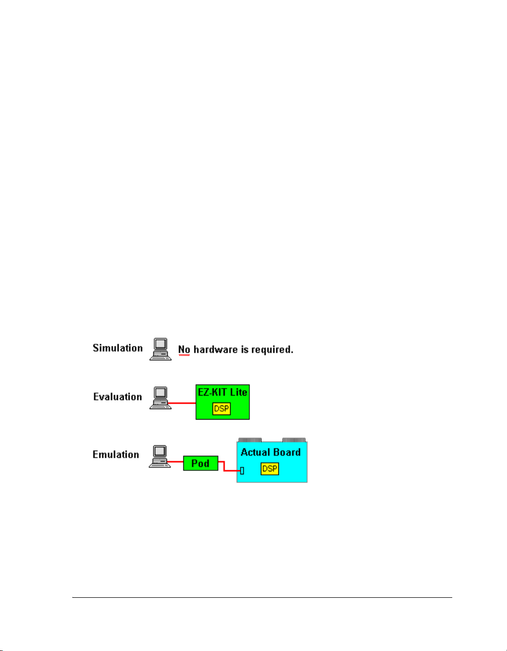
Introduction to VisualDSP++
Testing and Debugging With VisualDSP++:
At this stage, you should have a good understanding of the various facilities available for producing optimal software. The last step, applying
software testing and debugging techniques, includes:
• Collecting and viewing data using the advanced plot windows
• Using compiled simulation
• Using ActiveX and COM Automation to create regression test
environments and taking advantage of interoperability with other
applications
Project Development Stages
The typical project includes three phases: simulation, evaluation, and
emulation. These phases are shown in Figure 1-1.
Figure 1-1. Project Development Stages
VisualDSP++ provides debugging tools for each of these phases; refer to
Table 1-3 on page 1-23.
VisualDSP++ 4.5 User’s Guide 1-17
Page 54

Project Development
Simulation
Project development typically begins in a simulation environment while
hardware engineers are developing the new hardware (cell phone, computer, and so on). Simulation mimics system memory and I/O, which
allows portions of the target system hardware behavior to be viewed. A
simulator is software that mimics the behavior of a processor. Running
VisualDSP++ with a simulation target (without a physical processor)
enables you to build, edit, and debug your program, even before a processor is manufactured.
Evaluation
Use an EZ-KIT Lite evaluation system in your project’s early planning
stage to determine the processor that best fits your needs. Your PC connects to the EZ-KIT Lite board via a cable, enabling you to monitor
processor behavior.
Emulation
Once the hardware is ready, move directly to a JTAG emulator, which
connects your PC to the actual processor target board. Emulators provide
fast communications between the board and your PC. An emulator
enables application software to be downloaded and debugged from within
VisualDSP++. Emulator software performs the communications that
enable you to see how your code affects processor performance.
1-18 VisualDSP++ 4.5 User’s Guide
Page 55

Introduction to VisualDSP++
Targets
A target (or debug target) refers to the communication channel between
VisualDSP++ and a processor (or group of processors). A target can be a
simulator, EZ-KIT Lite evaluation board, or an emulator. Your system
can include multiple targets.
For example, the JTAG emulator communicates with one or more
physical devices over the host PC’s PCI bus, and the HPUSB-ICE
emulator communicates with a device via the PC’s USB port.
Simulation Targets
A simulation target, such as the ADSP-2106x Family Simulator, is a pure
software module and does not require the presence of a processor or any
related hardware for debugging.
During simulation, VisualDSP++ reads an executable (.DXE) file and executes it in software, similar to the way a processor executes a processor
image in hardware. VisualDSP++ simulates the memory and I/O devices
specified in an .LDF file. Some processors permit you to run a compiled
simulation. Refer to “Compiled Simulation” on page D-44.
Hardware Simulation
When connected to a simulation target in VisualDSP++, you can simulate
the following hardware conditions.
• Random interrupts that can occur during program execution
• Data transfer through the processor’s I/O pins
• Processor booting from a PROM or host processor
Setting up VisualDSP++ to generate random interrupts during program
execution enables you to exercise interrupt service routines (ISR) in your
code.
VisualDSP++ 4.5 User’s Guide 1-19
Page 56

Project Development
EZ-KIT Lite Targets
An EZ-KIT Lite target is a development board used to evaluate a particular
processor. Analog Devices provides EZ-KIT Lite evaluation systems (for each
processor family) and demonstration programs.
Emulator Targets
An emulator target is a module that controls a physical processor connected to a JTAG emulator system. For example, the USB-ICE emulator
communicates with one or more physical devices through the host USB
port.
Platforms
A platform refers to the configuration of processors with which a target
communicates. Several platforms may exist for a given debug target. For
example, if three emulators are installed on your system, you might select
emulator 2 as the platform that you want to use. The platform that you
use depends on your project development stage. (See Table 1-2.)
Table 1-2. Development Stages and Supported Platforms
Stage Platform
Simulation Typically one or more processors of the same type. By default, the plat-
form name is the identical simulator. Some processors support compiled
simulation; refer to “Compiled Simulation” on page D-44.
Evaluation An EZ-KIT Lite evaluation system
Emulation Any combination of devices. You configure the platform for a particular
target with the VisualDSP++ Configurator. When the debug target is a
JTAG emulator, “platform” refers to a JTAG chain of specific device types.
VisualDSP++ Configurator
Use the VisualDSP++ Configurator (Figure 1-2) to align the external
hardware target with an emulator so that the appropriate IDDE debug session can be established.
1-20 VisualDSP++ 4.5 User’s Guide
Page 57

Figure 1-2. VisualDSP++ Configurator
Introduction to VisualDSP++
After the EZ-KIT Lite evaluation system or emulator has been connected,
powered up, and recognized in the Windows Device Manager, you can
select or create the appropriate platform needed for configuring a debug
session. If the appropriate platform is not shown, you can create or configure one by specifying its name, type and JTAG chain (scan path).
You can also use the VisualDSP++ Configurator to run ICE Test, a utility
that checks the functionality of your emulator; refer to Figure 1-3.
Refer to VisualDSP++ Help for details about using the VisualDSP++
Configurator and the ICE Test utility.
VisualDSP++ 4.5 User’s Guide 1-21
Page 58
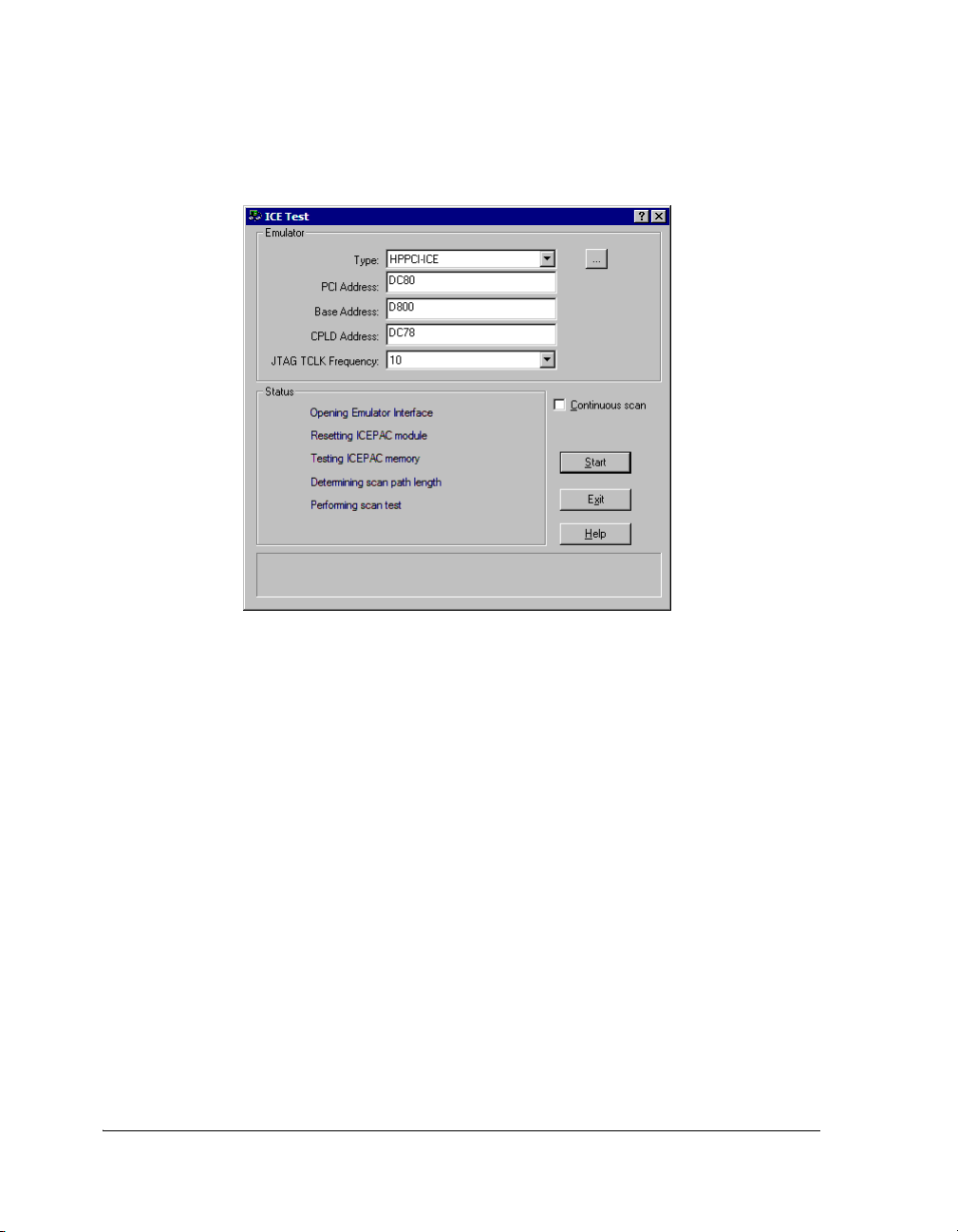
Project Development
Figure 1-3. ICE Test Utility
1-22 VisualDSP++ 4.5 User’s Guide
Page 59

Introduction to VisualDSP++
Debugging Overview
Once you have successfully built a processor project and generated an
executable file, you can debug the project. Projects developed in
VisualDSP++ are run as hardware and software debug sessions.
In Table 1-3, check marks (D) indicate the debugging tools that are
available during the process of building and debugging a program.
Table 1-3. Tools Available During Simulation, Evaluation, and Emulation
Tool Simulation Evaluation Emulation
Linear profiles on page 3-8
Interrupts on page 3-17
Streams on page 3-17
Traces (SHARC processors only)
on page 3-9
Pipeline Viewer (not SHARC processors)
on page C-2
Cache Viewer on page 2-84
Breakpoints on page 3-13
Watchp oi nt s on page 3-15
Hardware breakpoints on page 3-16
Plotting on page 3-20
Statistical profiles on page 3-8
D
D
D
D
D
D
DDD
D
D
DDD
D
VisualDSP++ 4.5 User’s Guide 1-23
Page 60

Project Development
You can attach to and control the operation of any Analog Devices
processors or simulator. Download your application code to the processor
and use VisualDSP++’s debugging facilities to ensure that your application
functions as desired.
VisualDSP++ is a window into the inner workings of the target processor
or simulator. From this user interface, you can:
• Run, step, and halt the program and set breakpoints and
watchpoints
• View the state of the processor’s memory, registers, and stacks
• Perform a cycle-accurate statistical profile or linear profile
• Perform integrated multiprocessor debugging (emulator sessions
only)
1-24 VisualDSP++ 4.5 User’s Guide
Page 61

Introduction to VisualDSP++
VisualDSP++ Kernel
A project can optionally include the VisualDSP++ Kernel (VDK), which is
a software executive between algorithms, peripherals, and control logic.
The Project window’s Kernel tab accesses a tree control for structuring
and scaling application development. From this tree control, you can add,
modify, and delete Kernel elements such as thread types, boot threads,
round-robin priorities, semaphores, events, event bits, interrupts, and
device drivers.
Two VDK-specific windows, VDK State History and Target Load, pro-
vide views of VDK information. Another VDK window, VDK Status,
provides thread status data when a VDK-enabled program is halted. Refer
to the VisualDSP++ Kernel (VDK) User’s Guide for details.
Program Development Steps
In the VisualDSP++ environment, program development consists of the
following steps.
1. Create a project.
2. Configure project options.
3. Add and edit project source files.
4. Specify project build options.
5. Build a debug version (executable file) of the project.
6. Create a debug session and load the executable.
7. Run and debug the program.
8. Build a release version of the project.
VisualDSP++ 4.5 User’s Guide 1-25
Page 62

Project Development
By following these steps, you can build projects consistently and accurately with minimal project management. This process reduces
development time and lets you concentrate on code development.
These steps, described below, are covered in detail in VisualDSP++ Help
and in the “Basic Tutorial” chapter of the VisualDSP++ Getting Started
Guide.
Step 1: Create a Project
All development in VisualDSP++ occurs within a project. The project
(
.DPJ) file stores your program’s build information: source files list and
development tools option settings.
VisualDSP++ includes a Project wizard that simplifies the creation of a
new project. Refer to the VisualDSP++ Getting Started Guide for a tutorial
or to VisualDSP++ Help.
Step 2: Configure Project Options
Define the target processor and set up your project options (or accept
default settings) before adding files to the project. The Project Options
dialog box provides access to project options (also called property pages),
which enable the corresponding build tools to process the project’s files
correctly.
Step 3: Add and Edit Project Source Files
A project normally contains one or more C, C++, or assembly language
source files. After creating a project and defining its target processor, add
new or existing files to the project by importing or writing them. Use the
VisualDSP++ editor to create new files or edit any existing text files.
Adding Files to Your Project
You can add any type of file to the project. The development tools selectively process only recognized file types when you build the project.
1-26 VisualDSP++ 4.5 User’s Guide
Page 63

Introduction to VisualDSP++
Creating Files to Add to Your Project
You can create new text files. The editor can read or write text files with
arbitrary names. Adding files to your project updates the project’s file tree
in the Project window.
Editing Files
You can edit the file(s) that you add to the project. To open a file for
editing, double-click on the file icon in the Project window.
The editor has a standard Windows-style user interface and supports
normal editing operations and multiple open windows. You can customize
language- and processor-specific syntax coloring, and create and search for
bookmarks.
Managing Project Dependencies
Project dependencies control how source files use information in other
files, and consequently determine the build order. VisualDSP++ maintains
a makefile, which stores dependency information for each file in the
project. VisualDSP++ updates dependency information when you change
the project’s build options, add a file to the project, or choose Update
Dependencies from the Project menu.
Step 4: Specifying Project Build Options
After creating a project, setting the target processor, and adding or editing
the project’s source files, configure your project’s build options. Specify
options or accept the default options in VisualDSP++ before using the
development tools that create your executable file. You can specify options
for a whole project or for individual files, or you can specify a custom
build.
L
VisualDSP++ 4.5 User’s Guide 1-27
VisualDSP++ retains your changes to the build options. Settings
reflect your last changes, not necessarily the original defaults.
Page 64

Project Development
Configuration
A project’s configuration setting controls its build. By default, the choices
are Debug or Release.
• Selecting Debug and leaving all other options at their default settings builds a project that can be debugged. The compiler generates
debug information.
• Selecting Release and leaving all other options at their default settings builds a project with limited or no debug capabilities. Release
builds are usually optimized for performance. Your test suite
should verify that the Release build operates correctly without
introducing significant bugs.
You can modify VisualDSP++’s default operation for either configuration
by changing the appropriate entries on the Compile, Assemble, and Link
pages. You can create custom configurations that include the build
options and source files that you want.
Project-Wide File and Tool Options
Next, you must decide whether to use project-wide option settings or
individual file settings.
For projects built entirely within VisualDSP++ with no pre-existing object
or archive (library) files, you typically use project-wide options. New files
added to the project inherit these settings.
Individual File and Tool Options
Occasionally, you may want to specify tool settings for individual files.
Each file is associated with two property pages: a General page, which lets
you choose output directories for intermediate and output files, and a
tool-specific property page (Compile, Assemble, Link, and so on), which
lets you choose options. For information about each tool’s options, see the
online Help or the manual for each tool.
1-28 VisualDSP++ 4.5 User’s Guide
Page 65

Introduction to VisualDSP++
Step 5: Build a Debug Version of the Project
Next, build a debug version of the project.
Status messages from each code development tool appear in the Output
window as the build progresses.
L
Step 6: Create a Debug Session and Load the Executable
After successfully building an executable file, set up a debug session. You
run projects that you develop as hardware or software sessions. After
specifying the processor, connection type, and platform, load your
project’s executable file. From the General page of the Preferences dialog
box, you can configure VisualDSP++ to load the file automatically and
advance to the main function of your code.
Step 7: Run and Debug the Program
After successfully creating a debug session and building and loading your
executable program, run and debug the program.
If the project is not current (has outdated source files or dependency
information), VisualDSP++ prompts you to build the project before
loading and debugging the executable file.
Step 8: Build a Release Version of the Project
The output file type must be an executable (.DXE) file to produce
debugger-compatible output.
After you finish debugging your application, build a Release version of
your project to run on the product’s processor.
VisualDSP++ 4.5 User’s Guide 1-29
Page 66

Code Development Tools
Code Development Tools
This section describes the following development tools.
• C/C++ compiler with run-time libraries
•Assembler
•Linker
• Expert Linker
• Preprocessor
• Archiver
• Splitter
•Loader
Available code development tools differ, depending on the processor.
The options available on the pages of the Project Options dialog box
enable you to specify tool preference.
VisualDSP++ supports ELF/DWARF-2 (Executable Linkable Format/
Debug With Arbitrary Records Format) executable files. VisualDSP++
supports all executable file formats produced by the linker.
If your system is configured with third-party development tools, you can
select the compiler, assembler, or linker to be used for a particular target
build.
1-30 VisualDSP++ 4.5 User’s Guide
Page 67

Introduction to VisualDSP++
Compiler
The compiler processes C/C++ programs into assembly code. The term
compiler refers to the compiler utility shipped with the VisualDSP++
software.
The compiler generates a linkable object file by compiling one or more
C/C++ source files. The compiler’s primary output is a linkable object file
with a .DOJ extension.
To specify compiler options for your build, choose Project -> Project
Options. From the tree control of the ensuing Project Options dialog
box, expand Compile and click a subpage.
Compiler options are grouped into the subpages described in Table 1-4.
Table 1-4. Compiler Option Subpages
Category Provides
General Optimization, compilation, and termination options
Source Language
Settings
Preprocessor Macro and directory search options
Processor Processor-specific options
Profile-guided
Optimization
Warning Warning and error reporting options
Settings related to the dialect of C or C++ accepted by the compiler
Options used while performing profile-guided optimization (PGO)
The available subpages and options depend on your target proces-
L
sor and your code development tools.
For more information about compile options, refer to your processor’s
VisualDSP++ C/C++ Compiler and Library manual and VisualDSP++
Help.
VisualDSP++ 4.5 User’s Guide 1-31
Page 68

Code Development Tools
C++ Run-Time Libraries
L
The C and C++ run-time libraries (RTLs) are collections of functions,
macros, and class templates that can be called from source programs.
Many functions are implemented in the processor assembly language.
C and C++ programs depend on library functions to perform operations
that are basic to the C and C++ programming languages. These operations
include memory allocations, character and string conversions, and math
calculations. The libraries also include multiple signal processing functions that ease processor code development. The RTL simplifies software
development by providing code for a variety of common needs.
The compiler provides a broad collection of C functions including those
required by the ANSI standard and additional Analog Devices-supplied
functions of value for processor programming. This release of the compiler
software includes both the Standard C Library and the Abridged Library, a
conforming subset of the Standard C++ Library. For more information
about the algorithms on which many of the C library’s math functions are
based, refer to the Cody and Waite text Software Manual for the Elemen-
tary Functions from Prentice Hall (1980).
You must be running VisualDSP++ to use the C++ run-time
libraries.
For more information about the C++ library portion of the ANSI/ ISO
Standard for C++, refer to the Plauger text Draft Standard C++ Library
from Prentice Hall (1994) (ISBN: 0131170031).
Dinkum Abridged C++ Library
The Dinkum Abridged C++ library software documentation is located on
the VisualDSP++ installation CD in the Docs\Reference folder. Viewing
or printing these files requires a browser, such as Internet Explorer 5.01
(or higher). You can copy these files from the installation CD onto
another disk.
1-32 VisualDSP++ 4.5 User’s Guide
Page 69

Introduction to VisualDSP++
Assembler
The assembler generates an object file by assembling source, header, and
data files. The assembler’s primary output is an object file with a .DOJ
extension.
To specify assembler options, choose Project -> Project Options, and
click Assemble (in the Project Options dialog box).
Assembler terms are defined as follows.
instruction set
Set of assembly instructions that pertain to a specific processor. For information about the instruction set, refer to your processor’s hardware documentation.
preprocessor commands
Commands that direct the preprocessor to include files, perform macro substitutions, and control conditional assembly
assembler directives
Directives that tell the assembler how to process source code and
set up processor features. Use directives to structure your program
into logical segments or sections that support the use of a Linker
Description File (.LDF) to construct an image suited to the target
system.
For detailed information, refer to the VisualDSP++ Assembler and
Preprocessor Manual or VisualDSP++ Help
VisualDSP++ 4.5 User’s Guide 1-33
Page 70

Code Development Tools
Linker
The linker links separately assembled files (object files and library files) to
produce executable (.DXE) files, shared memory (.SM) files, and overlay
(.OVL) files, which can be loaded onto the target.
The linker’s output files (
.DXE, .SM, .OVL) are binary, executable, and linkable
files (ELF). To make an executable file, the linker processes data from a
Linker Description File (
.LDF) and one or more object (.DOJ) files. The
executable files contain program code and debugging information. The linker
fully resolves addresses in executable files.
To specify linker options, choose Project -> Project Options, and click
Link tab (on the Project Options dialog box). From the Link page, select
a Category of options. Linker options are grouped into the following
subpages.
• General
• LDF Preprocessing
• Elimination
•Processor
Linker terms are defined as follows.
link against
Functionality that enables the linker to resolve symbols to which
multiple executables refer. For instance, shared memory (.SM)
executable files contain sections of code that other processor
executable (
.DXE) files link against. Through this process, a shared
item is available to multiple executable files without being
duplicated.
1-34 VisualDSP++ 4.5 User’s Guide
Page 71

link objects
Introduction to VisualDSP++
Object files (
executable (.DXE, .SM, .OVL) files, that are linked against
.LDF file
File that contains the commands, macros, and expressions that control how the linker arranges your program in memory
memory
Definitions that provide a description of your target processor system to the linker
overlays
Files that your overlay manager swaps in and out of run-time memory, depending on code operations. The linker produces overlay (.OVL) files.
sections
Declarations that identify the content for each executable file that the linker produces
.DOJ) that become linked and other items, such as
For detailed information, refer to the VisualDSP++ Linker and Utilities
Manual or VisualDSP++ Help.
Linker Description File (.LDF)
A Linker Description File (
.LDF) describes the target system and maps
your program code with the system memory and processors.
The .LDF file creates an executable file by using:
• The target system memory map
• Defined segments in your source files
VisualDSP++ 4.5 User’s Guide 1-35
Page 72

Code Development Tools
The parts of an
.LDF file, from the beginning to the end of the file, are
described as follows.
• Memory map – describes the processor’s physical memory (located
at the beginning of the .LDF file)
• SEARCH_DIR, $LIBRARIES, and $OBJECTS commands – define the
path names that the linker uses to search and resolve references in
the input files
• MEMORY command – defines the system’s physical memory and
assigns labels to logical segments within it. These logical segments
define program, memory, and stack memory types.
• SECTIONS command – defines the placement of code in physical
memory by mapping the sections specified in program files to the
sections declared in the MEMORY command. The INPUT_SECTIONS
statement specifies the object file that the linker uses to resolve the
mapping.
For details, refer to the VisualDSP++ Linker and Utilities Manual.
1-36 VisualDSP++ 4.5 User’s Guide
Page 73

Introduction to VisualDSP++
Expert Linker
Expert Linker is a graphical tool that enables you to:
• Define a target processor’s memory map
• Place a project’s object sections into that memory map
• View how much stack or heap has been used after you run a processor
program
This interactive tool speeds up the configuration of system memory. It uses
your application’s target memory description, object files, and libraries to create a memory map that you can manipulate to optimize your system’s use of
memory.
L
Expert Linker graphically displays the available project information in an .LDF
file as input. This information includes object files, LDF macros, libraries,
and target memory descriptions. Use the drag-and-drop function to arrange
the object files in a graphical memory-mapping representation. When you are
satisfied with the memory layout, generate the executable file (.DXE) via
VisualDSP++ project options.
L
When opened in a project that already includes an
parses the
map and the object mappings. The memory map appears in the Expert
Linker window (Figure 1-4 on page 1-39). Use this display to modify the
memory map or the object mappings. When the project is ready to be built,
Expert Linker saves the changes to the .LDF file.
Expert Linker works with the linker. For more information about
linking, refer to the VisualDSP++ Linker and Utilities Manual.
You can use default .LDF files that come with VisualDSP++ or the
Expert Linker wizard to create and customize a new
.LDF file, Expert Linker
.LDF file and graphically displays the target processor’s memory
.LDF file.
VisualDSP++ 4.5 User’s Guide 1-37
Page 74

Code Development Tools
Expert Linker can graphically display space allocated to program heap and
stack. After you load and run your program, Expert Linker indicates the used
portion of the heap and stack. You can then reduce the size of the heap or
stack to minimize the memory allocated for the heap and stack. Freeing up
memory in this way enables it to be used for storing other things like processor code or data.
You can launch the Expert Linker (see Figure 1-4) from VisualDSP++ in
three ways:
• Double-click the
.LDF file in the Project window.
• Right-click the .LDF file in the Project window to display a menu and
then choose Open in Expert Linker.
• From the VisualDSP++ main menu, choose Tools, Expert Linker,
and Create LDF.
Expert Linker Window
The Expert Linker window (Figure 1-4) enables you to modify the memory map or the object mappings. You can specify a color for each type of
object (internal memory, external memory, unused memory, reserved
memory, output sections, object sections, overlays in live space, and overlays in run space). The objects are displayed in color when you view the
Memory Map pane in graphical memory map mode. When the project is
ready to be built, Expert Linker saves the changes to the .LDF file.
The Expert Linker window contains two main panes:
• The Input Sections pane displays a tree structure of the input
sections.
• The Memory Map pane displays each memory map in a tree or
graphical representation.
1-38 VisualDSP++ 4.5 User’s Guide
Page 75

Introduction to VisualDSP++
Figure 1-4. Expert Linker Window
You can dock or float the Expert Linker window in the VisualDSP++
main window.
Memory Map Pane Right-Click Menu
Table 1-5 describes the commands on the Memory Map right-click menu.
Table 1-5. Memory Map Pane Right-Click Menu
Command Purpose
View ModevMemory Map Tree Displays the memory map in tree mode
View ModevGraphical
Memory Map
ViewvMapping Strategy
(Pre-Link)
ViewvLink Results (Post-Link) Displays the memory map, which shows where the object sections
NewvMemory Segment Opens the Memory Segment Properties dialog box, from which
Displays the memory map in graphical blocks
Displays the memory map, which shows where you intended to
place object sections
are actually placed
you specify the name, address range, type, width, and so on of the
memory segment that you want to add
VisualDSP++ 4.5 User’s Guide 1-39
Page 76

Code Development Tools
Table 1-5. Memory Map Pane Right-Click Menu (Cont’d)
Command Purpose
NewvOutput Section Adds an output section to the selected memory segment
Note: Right-click on a memory segment to access this command.
NewvShared Memory Opens the Shared Memory Properties dialog box, from which
you specify the name of the shared memory output file and processors that share the memory
This command is not available on single-processor systems.
NewvOverlay Opens the Overlay Properties dialog box, from which you add a
new overlay to the selected output section or memory segment
Note: The new overlay’s run space is in the selected output section.
Delete Deletes the selected object
Pin-to-Output Section Pins an object section to an output section to prevent it from over-
flowing to another output section
This command is available only after you right-click on an object
section that is part of an output section set to overflow to another
section.
View Section Contents Opens the Section Contents dialog box, which displays the con-
tents of the input or output section
This command is available only after you link or build the project
and then right-click on an input or object section.
1-40 VisualDSP++ 4.5 User’s Guide
Page 77

Introduction to VisualDSP++
Table 1-5. Memory Map Pane Right-Click Menu (Cont’d)
Command Purpose
Add Hardware Page Overlay
Support
View Symbols Opens the View Symbols dialog box and displays the symbols for
Expand All Expands all items in the memory map tree to make their contents
View Legend Opens the Legend dialog box, which shows all possible icons in the
Sets up hardware overlay live and run spaces for all available hardware pages by:
a) Checking if memory segments are currently defined in all hardware pages. If memory segments are located, you are queried about
whether to delete those segments.
b) Creating a memory segment containing an overlay (live space) in
each hardware page
c) Creating a memory segment containing all overlay run spaces in
hardware page 0
d) Creating a default mapping for each overlay. The default mapping maps objects containing the section, “
ware overlay on PM page 0, “pmpage1” to PM page 1, “dmpage0”
to DM page 0, and so on.
the project, overlay, or input section
This command is available after you link the project and then
right-click on the Memory Map pane for a processor, memory segment, output section, or input section.
visible
tree window, with a brief description of each icon.
The Colors page displays a list of colors used in the graphical
memory map. You can specify each object’s color.
pmpage0” to the hard-
View Global Properties Opens the Global Properties dialog box for the selected object.
The dialog box’s title and content depend on the selected object.
VisualDSP++ 4.5 User’s Guide 1-41
Page 78

Code Development Tools
Stack and Heap Usage
Expert Linker enables you to adjust the size of the stack and heap, and make
better use of memory.
Expert Linker can:
• Locate stacks and heaps and fill them with a marker value
This operation occurs after you load the program into a processor
target. The stacks and heaps are located by their memory segment
names, which may vary across processor families.
• Search the heap and stack for the highest memory locations written to
by the processor program
This operation occurs when the target halts after you run the program.
Assume that these values are the start of the unused portion of the
stack or heap. Expert Linker updates the memory map to show how
much of the stack and heap are unused.
Be aware of the following stack and heap restrictions.
• The heap, stack, and system stack must be defined in output sections
named
HEAP, STACK, and SYSSTACK, respectively.
• The heap, stack, and system stack must be the only items in those output sections. You cannot place other objects in those output sections.
For other processor families, the restrictions on memory segment names differ
according to what is used in the default
.LDF files. If you do not heed these
restrictions, you cannot view stack and heap usage after running your
program.
1-42 VisualDSP++ 4.5 User’s Guide
Page 79
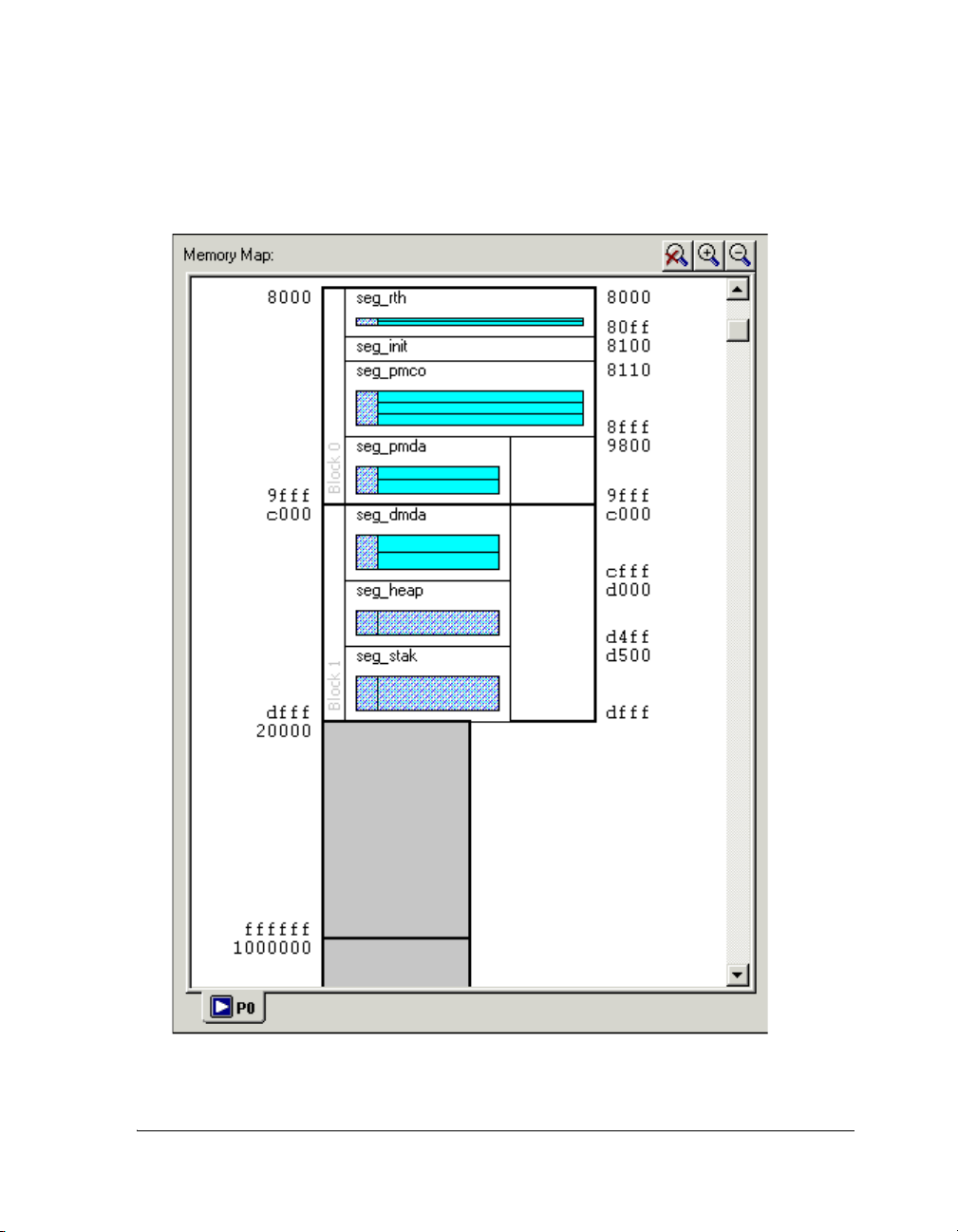
Introduction to VisualDSP++
Figure 1-5 shows an example memory map after you run a SHARC program.
Figure 1-5. Memory Map Example After Running a SHARC Program
VisualDSP++ 4.5 User’s Guide 1-43
Page 80

Code Development Tools
Archiver
The VisualDSP++ archiver (elfar.exe) combines object (.DOJ) files into
library (.DLB) files, which serve as reusable resources for project development. The linker searches library files for routines (library members)
referred to by other objects and links them in your executable program.
Run the archiver from within VisualDSP++ or from the command line.
From VisualDSP++, create a library file as your project’s output.
To modify or list the contents of a library file (or perform other operations
on it), you must run the archiver from a command line. For details, refer
to the VisualDSP++ Linker and Utilities Manual.
Splitter
The splitter (elfspl21k.exe) processes executable files to prepare
non-bootable programmable read-only memory (PROM) image files.
These files are executed from the processor’s external memory.
The splitter’s primary output is a PROM file with these extensions:
• .S_# (SHARC processors)
• .H_# (SHARC processors)
.STK (SHARC processors)
•
• .LDR (Blackfin and TigerSHARC processors)
For TigerSHARC processors, output from the splitter is 32 bit. For SHARC
processors, output from the splitter is 32 bit, 40 bit, 48 bit, or 64 bit.
To specify splitter options, choose Project > Project Options, and in the
tree control, click the Split page (or the Splitter subpage).
1-44 VisualDSP++ 4.5 User’s Guide
Page 81

Splitter terms are defined as follows.
non-bootable PROM-image files
The splitter’s output, which consists of PROM files that cannot be used to boot-load a system
splitter
Introduction to VisualDSP++
The splitter application, such as
software release
For more information about the splitter and options used to generate
loader files, refer to the VisualDSP++ Loader and Utilities Manual or
VisualDSP++ Help
elfspl21k.exe, contained in the
Loader
The loader (elfloader.exe) generates boot-loadable files by processing
executable files in addition to a loader kernel. The loader output (.LDR)
file enables the processor to boot from an external device (host or ROM).
L
To specify loader options, choose Project > Project Options, and open
the Load pages.
Loader terms are defined as follows:
boot kernel
The loader creates programs that execute from internal memory.
The splitter generates programs that execute from external
memory.
The executable file that performs memory initialization on the target
VisualDSP++ 4.5 User’s Guide 1-45
Page 82

Code Development Tools
boot-loadable file
The loader’s output (
.LDR), which contains the boot loader and the
formatted system configurations. This is a bootable image file.
boot loading
The process of loading the boot loader, initializing system memory, and starting the application on the target
loader
The loader application, such as elfloader.exe, contained in the software release
For more information about the loader, refer to the VisualDSP++ Loader
and Utilities Manual or VisualDSP++ Help.
1-46 VisualDSP++ 4.5 User’s Guide
Page 83

Introduction to VisualDSP++
Processor Projects
Your goal is to create a program that runs on a single-processor
(or multiprocessor) system. A project is the structure where programs are
built. All development in VisualDSP++ occurs within a project.
A project refers to the collection of source files and tool configurations
used to create a processor program. The project file (.DPJ) stores program
build information.
VisualDSP++ provides flexibility for setting up projects. You configure
settings for code development tools and configurations, and you specify
build settings for the project and for individual files. You can set up folders that contain your source files. A project can include VDK support.
Use the Project window to manage projects from start to finish. Within
the context of a project, you can:
• Specify code development tools
• Specify project-wide and individual-file options for Debug or
Release configurations of project builds
• Create source files
VisualDSP++ facilitates movement among editing, building, and debugging activities.
VisualDSP++ 4.5 User’s Guide 1-47
Page 84

Processor Projects
Project Options
Project options apply to the entire project. Specify project options in the
Project Options dialog box. Figure 1-6 shows an example of this
multi-paged dialog box.
Figure 1-6. Project Options Dialog Box Showing Project Page
For each code development tool (compiler, assembler, linker, splitter, and
loader), one or more pages provide options that control how each tool
processes inputs and generates outputs. The available pages depend on your
target. Options correspond to tool command-line switches. You can define
these options once or modify them to meet changing development needs.
L
1-48 VisualDSP++ 4.5 User’s Guide
Tools can also be accessed from the operating system’s command
line.
Page 85

Introduction to VisualDSP++
Project options also specify the following information.
• Project target
• Tool chain
• Output file directories
• Pre- and post-build options
Project Groups
A project group enables you to work with a number of projects at once. A
project group can be empty or contain any number of projects. Opening a
project adds it to the project group. Closing a project removes it from the
project group. Similar functionality is found in Microsoft Visual Studio.
The Project window (Figure 1-7) displays the project group icon and the
projects opened in that workspace.
Figure 1-7. Project Window
VisualDSP++ 4.5 User’s Guide 1-49
Page 86

Processor Projects
Each workspace has one project group. When you switch among workspaces, the project group is loaded and the same set of projects are opened
just as when you last closed the workspace.
One project is active at a time. The active project responds to commands and
messages from menus and toolbars. The Project window displays the active
project with bold typeface. A Project box, located by default with the toolbar
buttons, displays the name of the active project (see Figure 1-8).
Figure 1-8. Project Box Showing the Active Project
Though commands are sent to the active project, they may also be carried
out by a project on which the active project depends. For example, assume
that project A is active and depends on project B. Executing a Rebuild All
command on project A builds project B first. The same logic applies to the
Clean command, which deletes intermediate and target files.
Exporting a makefile exports one makefile for each open project. In the
makefile of a project depending on another project, one sub-target is created for each project on which it depends. Thus, building a project builds
all dependent projects first.
Project Group Files
You can save project group information to a file so you can restore that
project group and share it conveniently.
1-50 VisualDSP++ 4.5 User’s Guide
Page 87

Introduction to VisualDSP++
The project group file (
.DPG), which is in XML format, contains a list of
project entries. Each project entry corresponds to a project in the group
and contains project information, including the path to the project file
(.DPJ) and its dependent projects. Batch build specifications are saved in
the .DPG file for later use (so you can load and execute them without
re-specifying the same build targets). In the Project window, the root
node shows the project group’s file name without an extension.
Source Code Control (SCC)
VisualDSP++ includes Source Code Control (SCC), which enables you to
use the Microsoft Common Source Code Control (MCSCC) interface to
connect the VisualDSP++ IDDE to SCC applications installed on your
machine.
Various SCC products (such as Microsoft Visual SourceSafe or PVCS
Version Manager) support the MCSCC interface. From VisualDSP++
interface, you can access the commonly used features of these applications
without leaving the IDDE. You can launch the SCC application from the
plug-in menu to use non-supported features.
When you create a project, you are prompted to add the project to SCC.
When you open a project in the IDDE, the SCC plug-in connects to the
selected SCC application and locates a controlled copy of the project and
its source files. If a controlled copy is not located, the SCC application
must locate it. Typically, you are queried to browse for it. If the controlled
copy is successfully found or added, the plug-in keeps its application-specific path in the project file and reconnects with this path in the future.
You can subsequently reconnect to the controlled copy without having to
browse for it.
Operations executed on large numbers of files tend to take longer to finish. A message box provides status information by displaying the operation
currently executing. A button on the message box cancels the operation.
VisualDSP++ 4.5 User’s Guide 1-51
Page 88

Processor Projects
The Output window’s Console view displays finished operations. Messages indicate what has been done. Warnings and error messages may also
appear in the Output window.
SCC applications provide dialog boxes and GUI displays for some file
operations such as show history, show difference, and show properties.
These operations can be run from VisualDSP++.
For complete details, refer to VisualDSP++ Help.
Makefiles
Use a makefile (.MAK or .MK) to automate builds within VisualDSP++.
The output make rule is compatible with the gnumake utility (GNU
Make V3.77 or higher) or other make utilities. VisualDSP++ generates a
project makefile that controls the orderly sequence of code generation in
the target. You can also export a makefile for use outside of VisualDSP++.
For more information about makefiles, go to:
http://www.gnu.org/manual/make/
A project can have multiple makefiles, but only one makefile can be
enabled (active).
The project in Figure 1-9 includes an active makefile (indicated by ).
The active makefile, with its explicit
gmake command line, builds the
project. When no makefile is enabled for a project, VisualDSP++ uses
specifications configured in the Project Options dialog box.
1-52 VisualDSP++ 4.5 User’s Guide
Page 89

Introduction to VisualDSP++
Figure 1-9. Makefile in Project Window
You can view a makefile’s command line. To change the makefile’s target,
use the Configuration box, shown in Figure 1-10.
Figure 1-10. Makefile in Configuration Box
When you close a project, the Make commands and the target list associated with each makefile are serialized in the project (
.DPJ) file.
Rules
You can enable only one makefile when building a project. If you enable
more than one makefile, VisualDSP++ generates an error message. After
you build your project with an external makefile, the executable file is not
automatically loaded (even when this option is configured).
VisualDSP++ 4.5 User’s Guide 1-53
Page 90

Processor Projects
Output Window
Make command error messages and standard output appear in the Output
window. Double-clicking on an error-message position opens the makefile in
an editor window to the line of code causing the error.
Keywords in the makefile are syntax-colored.
Note: The error message format of
gmake is parsed correctly when you dou-
ble-click on an error message. If you use another make utility, the double-click
feature does not function.
Example Makefile
An example of a makefile appears below.
# Generated by the VisualDSP++ IDDE
# Note: Any changes made to this Makefile will be lost the next
# time the matching project file is loaded into the IDDE. If you
# wish to preserve changes, rename this file and run it
# externally to the IDDE.
# The syntax of this Makefile is such that GNU Make v3.77 or
# higher is required.
# The current working directory should be the directory in which
# this Makefile resides.
# Supported targets:
# Debug
# Debug_clean
# Release
# Release_clean
# Define ADI_DSP if it is not already defined. Define this
# variable if you wish to run this Makefile on a host other than
# the host that created it and VisualDSP++ may be installed in a
# different directory.
ifndef ADI_DSP
ADI_DSP=C:\Program Files\Analog Devices\VisualDSP
endif
# $VDSP is a gmake-friendly version of ADI_DIR
empty:=
1-54 VisualDSP++ 4.5 User’s Guide
Page 91

Introduction to VisualDSP++
space:= $(empty) $(empty)
VDSP_INTERMEDIATE=$(subst \,/,$(ADI_DSP))
VDSP=$(subst $(space),\$(space),$(VDSP_INTERMEDIATE))
# Define the command to use to delete files (which is different
# on Win95/98 and Windows NT/2000)
ifeq ($(OS),Windows_NT)
RM=cmd /C del /F /Q
else
RM=command /C del
endif
#
# Begin "Debug" configuration
#
ifeq ($(MAKECMDGOALS),Debug)
Debug : ./debug/mean.dxe
./debug/mean.doj :./mean.c ../../../include/stdio.h
$(VDSP)/cc21k -c .\Mean.c -g -proc ADSP-21062 -o
.\Debug\Mean.doj
./debug/benchmark.doj :./benchmark.asm
../../../include/asm_sprt.h ../../../include/def21060.h
$(VDSP)/easm21k.exe -proc ADSP-21062 -o .\Debug\benchmark.doj -g
.\benchmark.asm
./debug/mean.dxe :./debug/mean.doj ./debug/benchmark.doj
$(VDSP)/cc21k.exe .\Debug\Mean.doj .\Debug\benchmark.doj -proc
ADSP-21062 -L .\Debug -flags-link -od,.\Debug -o .\Debug\Mean.dxe
endif
ifeq ($(MAKECMDGOALS),Debug_clean)
Debug_clean:$(RM) ".\Debug\Mean.doj"
$(RM) ".\Debug\benchmark.doj"
$(RM) ".\Debug\Mean.dxe"
$(RM) ".\Debug\*.ipa"
$(RM) ".\Debug\*.opa"
$(RM) ".\Debug\*.ti"
endif
# Begin "Release" configuration
#
ifeq ($(MAKECMDGOALS),Release)
Release : ./release/mean.dxe
./release/mean.doj :./mean.c
VisualDSP++ 4.5 User’s Guide 1-55
Page 92

Processor Projects
$(VDSP)/cc21k -c .\Mean.c -O1 -proc ADSP-21062 -o
.\Release\Mean.doj
./release/benchmark.doj :./benchmark.asm
$(VDSP)/easm21k.exe -proc ADSP-21062 -o .\Release\benchmark.doj
.\benchmark.asm
./release/mean.dxe :./release/mean.doj ./release/benchmark.doj
$(VDSP)/cc21k.exe .\Release\Mean.doj .\Release\benchmark.doj
-proc ADSP-21062 -L .\Release -flags-link -od,.\Release -o
.\Release\Mean.dxe
endif
ifeq ($(MAKECMDGOALS),Release_clean)
Release_clean:
$(RM) ".\Release\Mean.doj"
$(RM) ".\Release\benchmark.doj"
$(RM) ".\Release\Mean.dxe"
$(RM) ".\Release\*.ipa"
$(RM) ".\Release\*.opa"
$(RM) ".\Release\*.ti"
endif
Project Configurations
By default, a project includes two configurations, Debug and Release,
described in Table 1-6. In previous software releases, the term configura-
tion was called “build type.”
Table 1-6. Default Project Configurations
Configuration Description
Debug Builds a project that enables the use of VisualDSP++
debugging capabilities
Release Builds a project with optimization enabled
Available configurations appear in the configuration box, which, by
default, is located in the Project toolbar, as shown in Figure 1-11.
You cannot delete the Release or Debug configuration.
L
1-56 VisualDSP++ 4.5 User’s Guide
Page 93
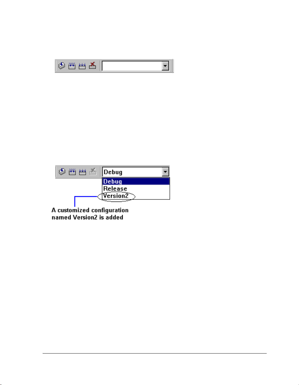
Introduction to VisualDSP++
Figure 1-11. Configuration Box
Customized Project Configurations
You can add a configuration to your project. A customized project configuration can include various project options and build options to help you
develop your project. Figure 1-12 shows a customized configuration
(Version2) listed in the configuration box.
Figure 1-12. Selecting a Project Configuration
Project Build
The term build refers to the process of performing operations (such as
preprocessing, assembling, and linking) on projects and files. During a
build, VisualDSP++ processes project files that have been modified since
the previous build as well as project files that include modified files.
A build differs from a rebuild all. When you execute the Rebuild All
command, VisualDSP++ processes all the files in the project, regardless of
whether they have been modified.
VisualDSP++ 4.5 User’s Guide 1-57
Page 94

Processor Projects
Building a project builds all outdated files in the project and enables you
to make your program. An outdated file is a file that has been modified
since the last time it was built or a file that includes (
#include) a modified
file. For example, if a C file that has not been modified includes a header
file that has been modified, the C file is out of date.
VisualDSP++ uses dependency information to determine which files,
if any, must be updated during a build.
L
Note the following:
• A file with an unrecognized file extension is ignored at build
time.
• If an included header file is modified, VisualDSP++ builds
the source files that include (#include) the header file,
regardless of whether the source files have been modified
since the previous build.
• File icons in the Project window indicate file status (such as
excluded files or files with specific options that override
project settings).
Build Options
You can specify options for the entire project and for individual files.
Table 1-7 describes these build options.
Table 1-7. Build Options
Options Description
Project Specify these options from a tabbed page (for example, Compile or
Link) for each of the code development tools.
Individual file These settings override project-wide settings.
Custom build For maximal flexibility, edit the command line(s) issued to build a
particular file. For example, you might call a third-party utility.
1-58 VisualDSP++ 4.5 User’s Guide
Page 95

Introduction to VisualDSP++
File Building
Building a file compiles or assembles the file and locates and removes errors.
You can build a single file or multiple files that you select.
The build process updates the selected source file’s output (.OBJ) file and
the output file’s debug information. Building a single file is very fast.
Large projects, however, may require hours to build.
If you change a common header file that requires a full build, you can build
only the current file to ensure that your change fixes the error in the current
file.
Batch Builds
Performing a batch build builds one or more build targets in the open
project group. You must configure the batch build before you can build it.
A build target in a project group is formed by the combination of a project
and a project configuration (such as a Release configuration). Refer to
VisualDSP++ Help for details on configuring and running a batch build.
Pre-Build and Post-Build Options
Pre-build and post-build options are typically DOS commands that are
executed before building a project and after a successful project build.
These commands invoke external tools. You can configure these options
via the Project Options dialog box.
For example, you can use a post-build command to copy the final output
file to another location on the hard drive or to invoke an application
automatically.
Automatically copying files and cleaning up intermediate files after a successful build can be very useful.
VisualDSP++ 4.5 User’s Guide 1-59
Page 96

Processor Projects
Command Syntax
Place “c:\windows\command.com /C” at the beginning of each DOS
command line. For example, to execute “copy a.txt b.txt”, type:
c:\windows\command.com /C copy a.txt b.txt
L
The letter “C” after the slash character must be uppercase.
Project Dependencies
Dependency data determines which files must be updated during a build. The
following are examples of dependency information.
..\.\.\include\cplus\cstddef
..\.\.\include\cplus\exception
..\.\.\include\cplus\new
..\.\.\include\cplus\xstddef
..\.\.\include\def21060.h
..\.\.\include\limits.h
..\.\.\include\cplus\stddef
..\.\.\include\stdio.h
..\.\.\include\string.h
..\.\.\include\VDK_Internals.h
..\.\.\include\VDK_Public.h
..\.\.\include\yvals.h
Project Window Rules
The Project window displays a project’s files, as shown in Figure 1-13.
1-60 VisualDSP++ 4.5 User’s Guide
Page 97

Introduction to VisualDSP++
Figure 1-13. Example of Project Files
The following rules dictate how files and subfolders behave in the Project
window’s file tree.
• You can include any file in a project.
• Only one
.LDF file is permitted.
• You cannot add the same file into the same project more than once.
• Only one project (project node) is permitted.
• A file with an unrecognized file extension is ignored at build time.
• When you add a file to a project, the file is placed in the first folder
configured with the same extension. If no such folders are present,
an added file goes to the project level.
VisualDSP++ 4.5 User’s Guide 1-61
Page 98

VisualDSP++ Help System
VisualDSP++ Help System
The VisualDSP++ Help system is designed to help you obtain information
quickly. Use the Help system’s table of contents, index, full-text search
function, and extensive hyperlinks to jump to topics. Bookmark topics
that you plan to revisit.
VisualDSP++ Help is comprised of multiple Help systems (.CHM files).
Each file is identified with a book icon in the software installation’s
Help folder.
The majority of the Help system files are VisualDSP++ manuals and hardware documentation. These manuals are also available in PDF format (on
the installation disk) for printing. Manuals are also available from Analog
Devices as printed books.
Each window, toolbar button, and menu-bar command in VisualDSP++ is
linked to a topic in Help. Other portions of the VisualDSP++ Help system
provide procedures for configuring and using tools.
Some .CHM files support pop-up messages for dialog box controls (buttons,
fields, and so on). These messages, which appear in little yellow boxes,
comprise part of the context-sensitive Help in VisualDSP++.
For more information about the Help system, refer to “Online Help” on
page A-54 and to “Using this Help System” in VisualDSP++ Help.
1-62 VisualDSP++ 4.5 User’s Guide
Page 99

2 ENVIRONMENT
VisualDSP++ is an intuitive, easy-to-use user interface for programming
Analog Devices processors. This chapter introduces the VisualDSP++
work environment, including the main window and debugging windows.
Graphics are used to illustrate concepts and available window options.
From the application’s main window, you can open the Project window,
editor windows, the Output window, and various debugging windows.
Customize VisualDSP++ to meet your needs. Refer to VisualDSP++ Help
for “how to” information. This chapter is organized as follows.
• “Project Window” on page 2-2
The Project window provides a project hierarchy.
• “Editor Windows” on page 2-13
Editor windows allow you to view and edit files.
• “Output Window” on page 2-24
This window provides I/O messages and a scripting input.
• “Debugging Windows” on page 2-39
This section focuses on each debugging window, presenting its
purpose, features, and benefits.
For information about the VisualDSP++ title bar, control menu, menu
bars, toolbars and user tools, and status bars, refer to“Parts of the User
Interface” on page A-15
VisualDSP++ 4.5 User’s Guide 2-1
Page 100

Project Window
Project Window
To open a Project window, choose View and Project Window. Figure 2-1
shows a Project window with VDK enabled.
Figure 2-1. Example Project Window With Kernel Tab
An additional folder, titled Generated Files, may be present when a
project includes startup files.
The Project window can include two sub-tabs:
• The Project tab , which is always available, displays a
hierarchal representation of a debug session’s projects, folders, files,
and dependencies.
• The Kernel tab appears when VDK is enabled for a
project. It displays VDK-related information.
2-2 VisualDSP++ 4.5 User’s Guide
 Loading...