

Page 1

W4.0
Linker and Utilities Manual
Analog Devices, Inc.
One Technology Way
Norwood, Mass. 02062-9106
Revision 1.0, January 2005
Part Number
82-000420-03
a
Page 2

Copyright Information
© 2005 Analog Devices, Inc., ALL RIGHTS RESERVED. This document may not be reproduced in any form without prior, express written
consent from Analog Devices, Inc.
Printed in the USA.
Disclaimer
Analog Devices, Inc. reserves the right to change this product without
prior notice. Information furnished by Analog Devices is believed to be
accurate and reliable. However, no responsibility is assumed by Analog
Devices for its use; nor for any infringement of patents or other rights of
third parties which may result from its use. No license is granted by implication or otherwise under the patent rights of Analog Devices, Inc.
Trademark and Service Mark Notice
The Analog Devices logo, the CROSSCORE logo, VisualDSP++,
Blackfin, SHARC, TigerSHARC, and EZ-KIT Lite are registered trademarks of Analog Devices, Inc.
All other brand and product names are trademarks or service marks of
their respective owners.
Page 3

CONTENTS
PREFACE
Purpose of This Manual ................................................................. xix
Intended Audience ......................................................................... xix
Manual Contents ............................................................................ xx
What’s New in This Manual ........................................................... xxi
Technical or Customer Support ..................................................... xxii
Supported Processors ................................................................... xxiii
Product Information .................................................................... xxiv
MyAnalog.com ....................................................................... xxiv
Processor Product Information ................................................. xxv
Related Documents ................................................................ xxvi
Online Technical Documentation .......................................... xxvii
Accessing Documentation From VisualDSP++ ................... xxvii
Accessing Documentation From Windows ........................ xxviii
Accessing Documentation From the Web .......................... xxviii
Printed Manuals ..................................................................... xxix
VisualDSP++ Documentation Set ....................................... xxix
Hardware Tools Manuals .................................................... xxix
Processor Manuals .............................................................. xxix
VisualDSP++ 4.0 Linker and Utilities Manual iii
Page 4

CONTENTS
Data Sheets ....................................................................... xxix
Notation Conventions .................................................................. xxx
INTRODUCTION
Software Development Flow ......................................................... 1-2
Compiling and Assembling ........................................................... 1-3
Inputs – C/C++ and Assembly Sources .................................... 1-3
Input Section Directives in Assembly Code .............................. 1-4
Input Section Directives in C/C++ Source Files ........................ 1-5
Linking ........................................................................................ 1-7
Linker and Assembler Preprocessor .......................................... 1-8
Loading and Splitting ................................................................. 1-10
LINKER
Linker Operation .......................................................................... 2-2
Directing Linker Operation ..................................................... 2-3
Linking Process Rules .............................................................. 2-4
Linker Description File Overview ............................................ 2-5
Linking Environment ................................................................... 2-6
Project Builds ......................................................................... 2-6
Expert Linker ........................................................................ 2-14
Linker Warning and Error Messages ...................................... 2-15
Link Target Description .............................................................. 2-16
Representing Memory Architecture ........................................ 2-17
Specifying the Memory Map ................................................. 2-17
iv VisualDSP++ 4.0 Linker and Utilities Manual
Page 5

CONTENTS
Memory Usage and Default Memory Sections .................... 2-18
Default Memory Sections for SHARC Processors ............... 2-19
seg_rth .......................................................................... 2-19
seg_init ......................................................................... 2-20
seg_int_code ................................................................. 2-20
seg_pmco ...................................................................... 2-20
seg_pmda ...................................................................... 2-20
seg_argv ........................................................................ 2-20
seg_ctdm ...................................................................... 2-20
seg_dmda ...................................................................... 2-21
seg_heap ....................................................................... 2-21
seg_stak ........................................................................ 2-21
seg_vtbl ........................................................................ 2-21
Other Memory Sections ................................................ 2-21
Default Memory Sections for TigerSHARC Processors ....... 2-22
program ........................................................................ 2-23
data1 ............................................................................ 2-23
data2 ............................................................................ 2-23
mem_argv ..................................................................... 2-23
ctor ............................................................................... 2-23
heaptab ......................................................................... 2-24
bsz ................................................................................ 2-24
bsz_init ......................................................................... 2-24
M1Stack ....................................................................... 2-24
VisualDSP++ 4.0 Linker and Utilities Manual v
Page 6

CONTENTS
Default Memory Sections for Blackfin Processors .............. 2-25
M2Stack ....................................................................... 2-24
M1Heap ....................................................................... 2-24
vtbl .............................................................................. 2-25
program ....................................................................... 2-26
data1 ............................................................................ 2-26
cplb_code ..................................................................... 2-26
constdata ...................................................................... 2-27
cplb_data ..................................................................... 2-27
L1_DATA_A ................................................................ 2-27
L1_DATA_B ................................................................ 2-27
voldata ......................................................................... 2-27
argv .............................................................................. 2-28
ctor .............................................................................. 2-28
bsz ............................................................................... 2-28
bsz_init ........................................................................ 2-28
stack ............................................................................. 2-29
heap ............................................................................. 2-29
noncache_code ............................................................. 2-29
sdram0 ......................................................................... 2-29
vtbl .............................................................................. 2-29
Other Memory Sections ................................................ 2-30
Special “Table” Memory Sections ...................................... 2-30
.gdt .............................................................................. 2-30
vi VisualDSP++ 4.0 Linker and Utilities Manual
Page 7

CONTENTS
.gdtl .............................................................................. 2-30
.edt ............................................................................... 2-30
.edtl .............................................................................. 2-31
.cht ............................................................................... 2-31
.chtl .............................................................................. 2-31
.frt ................................................................................ 2-31
.frtl ............................................................................... 2-31
Memory Characteristics Overview ..................................... 2-31
SHARC Memory Characteristics ................................... 2-32
TigerSHARC Memory Characteristics ........................... 2-34
Blackfin Processor Memory Characteristics .................... 2-36
Linker MEMORY{} Command in .LDF File ...................... 2-38
Placing Code on the Target .................................................... 2-40
Specifying Two Buffers in Different Memory Segments ...... 2-44
Profile-Guided Optimization Support .................................... 2-45
Passing Arguments for Simulation or Emulation ..................... 2-46
Linker Command-Line Reference ................................................ 2-47
Linker Command-Line Syntax ............................................... 2-47
Command-Line Object Files ............................................. 2-48
Command-Line File Names ............................................... 2-49
Object File Types .............................................................. 2-51
Linker Command-Line Switches ............................................ 2-51
Linker Switch Summary and Descriptions .......................... 2-53
@filename ......................................................................... 2-55
VisualDSP++ 4.0 Linker and Utilities Manual vii
Page 8

CONTENTS
-Dprocessor ...................................................................... 2-55
-L path ............................................................................. 2-56
-M ................................................................................... 2-56
-MM ................................................................................ 2-56
-Map filename .................................................................. 2-56
-MDmacro[=def] .............................................................. 2-57
-MUDmacro .................................................................... 2-57
-S ..................................................................................... 2-57
-T filename ...................................................................... 2-58
-Wwarn [number] ............................................................ 2-58
-Wnumber[,number] ........................................................ 2-58
-e ..................................................................................... 2-59
-ek sectionName ............................................................... 2-59
-es sectionName ............................................................... 2-59
-ev ................................................................................... 2-59
-flags-meminit -opt1[,-opt2... .......................................... 2-60
-flags-pp-opt1[,-opt2...] ................................................... 2-60
-h[elp] .............................................................................. 2-60
-i|I directory ..................................................................... 2-60
-ip .................................................................................... 2-60
-jcs2l ................................................................................ 2-61
-jcs2l+ .............................................................................. 2-62
-keep symbolName ........................................................... 2-62
-meminit .......................................................................... 2-62
viii VisualDSP++ 4.0 Linker and Utilities Manual
Page 9

CONTENTS
-nonmemcheck ................................................................. 2-62
-o filename ....................................................................... 2-63
-od directory ..................................................................... 2-63
-pp ................................................................................... 2-63
-proc processor .................................................................. 2-63
-s ...................................................................................... 2-64
-save-temps ....................................................................... 2-64
-si-revision version ............................................................ 2-64
-sp .................................................................................... 2-65
-t ...................................................................................... 2-65
-v[erbose] ......................................................................... 2-65
-version ............................................................................ 2-66
-warnonce ......................................................................... 2-66
-xref filename .................................................................... 2-66
LINKER DESCRIPTION FILE
LDF File Overview ....................................................................... 3-3
Default LDFs .......................................................................... 3-3
Example 1 – Basic .LDF File for Blackfin Processors ................. 3-6
Memory Usage in Blackfin Processors .................................. 3-8
Example 2 – Basic .LDF File for TigerSHARC Processors ......... 3-9
Example 3 – Basic .LDF File for SHARC Processors ............... 3-10
Notes on Basic .LDF File Examples ........................................ 3-11
LDF Structure ............................................................................ 3-16
Command Scoping ................................................................ 3-17
VisualDSP++ 4.0 Linker and Utilities Manual ix
Page 10

CONTENTS
LDF Expressions ........................................................................ 3-18
LDF Keywords, Commands, and Operators ................................ 3-19
Miscellaneous LDF Keywords ................................................ 3-20
LDF Operators ........................................................................... 3-21
ABSOLUTE() Operator ........................................................ 3-21
ADDR() Operator ................................................................ 3-22
DEFINED() Operator .......................................................... 3-23
MEMORY_SIZEOF() Operator ............................................ 3-24
SIZEOF() Operator .............................................................. 3-24
Location Counter (.) ............................................................. 3-25
LDF Macros ............................................................................... 3-26
Built-In LDF Macros ............................................................ 3-27
User-Declared Macros ........................................................... 3-28
LDF Macros and Command-Line Interaction ........................ 3-28
LDF Commands ........................................................................ 3-29
ALIGN() .............................................................................. 3-30
ARCHITECTURE() ............................................................. 3-30
ELIMINATE() ...................................................................... 3-31
ELIMINATE_SECTIONS() ................................................. 3-32
INCLUDE() ......................................................................... 3-32
INPUT_SECTION_ALIGN() .............................................. 3-32
KEEP() ................................................................................. 3-33
KEEP_SECTIONS() ............................................................ 3-34
LINK_AGAINST() ............................................................... 3-34
x VisualDSP++ 4.0 Linker and Utilities Manual
Page 11

CONTENTS
MAP() .................................................................................. 3-35
MEMORY{} .......................................................................... 3-35
Segment Declarations ........................................................ 3-37
MPMEMORY{} .................................................................... 3-38
OVERLAY_GROUP{} ........................................................... 3-39
PACKING() .......................................................................... 3-39
Packing in SHARC Processors ........................................... 3-41
Overlay Packing Formats in SHARC Processors ............. 3-42
External Execution Packing in SHARC Processors .......... 3-43
PLIT{} .................................................................................. 3-45
PROCESSOR{} ..................................................................... 3-45
RESOLVE() .......................................................................... 3-47
SEARCH_DIR() ................................................................... 3-47
SECTIONS{} ........................................................................ 3-48
INPUT_SECTIONS() ...................................................... 3-51
expression ......................................................................... 3-52
FILL(hex number) ............................................................ 3-52
PLIT{plit_commands} ...................................................... 3-52
OVERLAY_INPUT{overlay_commands} ........................... 3-53
SHARED_MEMORY{} ......................................................... 3-55
EXPERT LINKER
Expert Linker Overview ................................................................ 4-2
Launching the Create LDF Wizard ................................................ 4-4
Step 1: Specifying Project Information ..................................... 4-5
VisualDSP++ 4.0 Linker and Utilities Manual xi
Page 12

CONTENTS
Step 2: Specifying System Information ..................................... 4-6
Step 3: Completing the LDF Wizard ....................................... 4-9
Expert Linker Window Overview ................................................ 4-10
Input Sections Pane .................................................................... 4-12
Input Sections Menu ............................................................. 4-12
Mapping an Input Section to an Output Section .................... 4-14
Viewing Icons and Colors ...................................................... 4-15
Sorting Objects ..................................................................... 4-17
Memory Map Pane ..................................................................... 4-19
Context Menu ...................................................................... 4-22
Tree View Memory Map Representation ................................ 4-24
Graphical View Memory Map Representation ........................ 4-25
Specifying Pre- and Post-Link Memory Map View ................. 4-31
Zooming In and Out on the Memory Map ............................ 4-32
Adding a Memory Segment ................................................... 4-33
Inserting a Gap Into a Memory Segment ............................... 4-35
Working With Overlays ........................................................ 4-36
Viewing Section Contents ..................................................... 4-38
Viewing Symbols .................................................................. 4-41
Profiling Object Sections ....................................................... 4-42
Adding Shared Memory Segments and Linking Object Files ... 4-46
Managing Object Properties ........................................................ 4-51
Managing General Global Properties ..................................... 4-52
Managing Processor Properties .............................................. 4-53
xii VisualDSP++ 4.0 Linker and Utilities Manual
Page 13

Managing PLIT Properties for Overlays ................................. 4-55
Managing Elimination Properties ........................................... 4-56
Managing Symbols Properties ................................................ 4-58
Managing Memory Segment Properties .................................. 4-61
Managing Output Section Properties ..................................... 4-62
Managing Packing Properties ................................................. 4-65
Managing Alignment and Fill Properties ................................ 4-67
Managing Overlay Properties ................................................. 4-69
Managing Stack and Heap in Processor Memory .................... 4-71
Managing Shared Memory Properties ..................................... 4-74
MEMORY OVERLAYS AND ADVANCED LDF
COMMANDS
Overview ...................................................................................... 5-2
Memory Management Using Overlays ........................................... 5-4
Introduction to Memory Overlays ............................................ 5-5
Overlay Managers .................................................................... 5-7
Breakpoints on Overlays ...................................................... 5-7
Memory Overlay Support ........................................................ 5-8
Example – Managing Two Overlays ....................................... 5-13
Linker-Generated Constants .................................................. 5-16
Overlay Word Sizes ................................................................ 5-16
Storing Overlay ID ................................................................ 5-19
Overlay Manager Function Summary ..................................... 5-20
Reducing Overlay Manager Overhead .................................... 5-20
VisualDSP++ 4.0 Linker and Utilities Manual xiii
Page 14

Using PLIT{} and Overlay Manager ....................................... 5-25
Inter-Overlay Calls ........................................................... 5-27
Inter-Processor Calls ......................................................... 5-27
Advanced LDF Commands ......................................................... 5-30
MPMEMORY{} .................................................................... 5-30
OVERLAY_GROUP{} .......................................................... 5-32
Ungrouped Overlay Execution .......................................... 5-33
Grouped Overlay Execution .............................................. 5-35
PLIT{} .................................................................................. 5-36
PLIT Syntax ..................................................................... 5-36
Command Evaluation and Setup ................................... 5-37
Overlay PLIT Requirements and PLIT Examples ............... 5-38
PLIT – Summary .............................................................. 5-40
SHARED_MEMORY{} ........................................................ 5-40
ARCHIVER
Archiver Guide ............................................................................. 6-2
Creating a Library From VisualDSP++ ..................................... 6-3
Making Archived Functions Usable ......................................... 6-3
Writing Archive Routines: Creating Entry Points ................. 6-4
Accessing Archived Functions From Your Code ................... 6-5
Archiver File Searches ......................................................... 6-6
Tagging an Archive With Version Information ..................... 6-6
Basic Version Information ............................................... 6-6
User-Defined Version Information .................................. 6-7
xiv VisualDSP++ 4.0 Linker and Utilities Manual
Page 15

Printing Version Information ........................................... 6-8
Removing Version Information From an Archive .............. 6-9
Checking Version Number .............................................. 6-9
Adding Text to Version Information .............................. 6-10
Archiver Command-Line Reference ............................................. 6-11
elfar Command Syntax .......................................................... 6-11
Archiver Parameters and Switches .......................................... 6-12
Command-Line Constraints .................................................. 6-14
Archiver Symbol Name Encryption ........................................ 6-15
MEMORY INITIALIZER
Memory Initializer Overview ......................................................... 7-2
Basic Operation of Memory Initializer ........................................... 7-3
Input and Output Files ............................................................ 7-3
Initialization Stream Structure ....................................................... 7-5
Run-Time Library Routine Basic Operation ................................... 7-6
Using the Memory Initializer ......................................................... 7-7
Preparing the Linker Description File (.LDF) ........................... 7-7
Preparing the Source Files ........................................................ 7-8
Invoking the Memory Initializer ............................................ 7-10
Invoking Memory Initializer from the VisualDSP++ IDDE 7-10
Invoking Memory Initializer from Command Line ............. 7-11
Invoking Memory Initializer from Linker’s Command Line 7-11
Invoking Memory Initializer from Compiler’s Command Line 7-11
Invoking Memory Initializer with Callback Executables ..... 7-11
VisualDSP++ 4.0 Linker and Utilities Manual xv
Page 16

Memory Initializer Command-Line Switches ............................... 7-13
-BeginInit Initsymbol ............................................................ 7-14
-h ......................................................................................... 7-15
-IgnoreSection Sectionname .................................................. 7-15
-Init Initcode.dxe .................................................................. 7-15
InputFile.dxe ........................................................................ 7-16
-NoAuto ............................................................................... 7-16
-NoErase ............................................................................... 7-16
-o Outputfile.dxe .................................................................. 7-17
-Section Sectionname ............................................................ 7-17
-SectDestination Sectionname ............................................... 7-17
-v ......................................................................................... 7-18
FILE FORMATS
Source Files .................................................................................. A-2
C/C++ Source Files ................................................................. A-2
Assembly Source Files (.ASM) ................................................. A-3
Assembly Initialization Data Files (.DAT) ................................ A-3
Header Files (.H) .................................................................... A-4
Linker Description Files (.LDF) .............................................. A-4
Linker Command-Line Files (.TXT) ........................................ A-5
Build Files .................................................................................... A-5
Assembler Object Files (.DOJ) ................................................ A-5
Library Files (.DLB) ................................................................ A-5
Linker Output Files (.DXE, .SM, and .OVL) ........................... A-6
xvi VisualDSP++ 4.0 Linker and Utilities Manual
Page 17

Memory Map Files (.XML) ..................................................... A-6
Loader Output Files in Intel Hex-32 Format (.LDR) ............... A-6
Splitter Output Files in ASCII Format (.LDR) ........................ A-8
Debugger Files ............................................................................. A-9
Format References ...................................................................... A-10
UTILITIES
elfdump – ELF File Dumper ........................................................ B-1
Disassembling a Library Member ............................................ B-3
Dumping Overlay Library Files ............................................... B-4
LDF PROGRAMMING EXAMPLES FOR TIGERSHARC
PROCESSORS
Linking a Single-Processor System ................................................ C-2
Linking Large Uninitialized or Zero-InitializedVariables ................ C-4
Linking an ADSP-TS101 MP Shared Memory System .................. C-6
Linking for Overlay Memory ...................................................... C-12
LDF PROGRAMMING EXAMPLES FOR SHARC
PROCESSORS
Linking a Single-Processor SHARC System ................................... D-2
Linking Large Uninitialized Variables ........................................... D-4
Linking for MP and Shared Memory ............................................ D-6
Reflective Semaphores .......................................................... D-11
Linking for Overlay Memory ...................................................... D-13
LDF PROGRAMMING EXAMPLES FOR BLACKFIN
VisualDSP++ 4.0 Linker and Utilities Manual xvii
Page 18

PROCESSORS
Linking for a Single-Processor System ........................................... E-2
Linking Large Uninitialized or Zero-initialized Variables ................ E-4
Linking for Assembly Source File .................................................. E-6
Linking for C Source File – Example 1 .......................................... E-8
Linking for Complex C Source File – Example 2 ......................... E-11
Linking for Overlay Memory ...................................................... E-17
INDEX
xviii VisualDSP++ 4.0 Linker and Utilities Manual
Page 19

PREFACE
Thank you for purchasing Analog Devices development software for digital signal processors (DSPs).
Purpose of This Manual
The VisualDSP++ 4.0 Linker and Utilities Manual contains information
about the linker and utilities programs for 16-bit fixed-point Blackfin®
(ADSP-BFxxx) processors, and 32-bit (floating-point and fixed-point)
TigerSHARC® (ADSP-TSxxx) and SHARC® (ADSP-21xxx) processors
which set a new standard of performance for digital signal processors,
combining multiple computation units for floating-point and fixed-point
processing as well as wide word width.
This manual provides information on the linking process and describes
the syntax for the linker’s command language—a scripting language that
the linker reads from the linker description file. The manual leads you
through using the linker, archiver, and utilities to produce DSP programs
and provides reference information on the file utility software.
Intended Audience
The primary audience for this manual is a programmer who is familiar
with Analog Devices processors. This manual assumes that the audience
has a working knowledge of the appropriate processor architecture and
instruction set. Programmers who are unfamiliar with Analog Devices
VisualDSP++ 4.0 Linker and Utilities Manual xix
Page 20

Manual Contents
processors can use this manual, but should supplement it with other texts
(such as the appropriate hardware reference and programming reference
manuals) that describe your target architecture.
Manual Contents
The manual contains:
• Chapter 1, “Introduction”
This chapter provides an overview of the linker and utilities.
• Chapter 2, “Linker”
This chapter describes how to combine object files into reusable
library files to link routines referenced by other object files.
• Chapter 3, “Linker Description File”
This chapter describes how to write an .LDF file to define the
target.
• Chapter 4, “Expert Linker”
This chapter describes Expert Linker, which is an interactive
graphical tool to set up and map processor memory.
• Chapter 5, “Memory Overlays and Advanced LDF Commands”
This chapter describes how overlays and advanced LDF commands
are used for memory management.
• Chapter 6 “Archiver”
This chapter describes the
object files into library files, which serve as reusable resources for
code development.
• Chapter 7 “Memory Initializer”
This chapter describes the Memory Initializer utility that is used to
generate a single initialization stream and save it in a section in the
output executable file.
xx VisualDSP++ 4.0 Linker and Utilities Manual
elfar archiver utility used to combine
Page 21

Preface
• Appendix A, “File Formats”
This appendix lists and describes the file formats that the development tools use as inputs or produce as outputs.
• Appendix B, “Utilities”
This appendix describes the utilities that provide legacy and file
conversion support.
• Appendix C, “LDF Programming Examples for TigerSHARC Pro-
cessors”
This appendix provides code examples of .LDF files used with
TigerSHARC processors.
• Appendix D, “LDF Programming Examples for SHARC Proces-
sors”
This appendix provides code examples of .LDF files used with
SHARC processors.
• Appendix E, “LDF Programming Examples for Blackfin Proces-
sors”
This appendix provides code examples of .LDF files used with
Blackfin processors.
What’s New in This Manual
This is a new manual that documents linking support for all currently
available Analog Devices 32-bit floating-point and fixed-point SHARC
and TigerSHARC
processors.
Loader/splitter information is now available in a separate Loader manual.
Refer to VisualDSP++ 4.0 Product Bulletin for information on all new and
updated features and other release information.
VisualDSP++ 4.0 Linker and Utilities Manual xxi
processors, as well as 16-bit fixed-point Blackfin
Page 22

Technical or Customer Support
Technical or Customer Support
You can reach Analog Devices, Inc. Customer Support in the following
ways:
• Visit the Embedded Processing and DSP products Web site at
http://www.analog.com/processors/technicalSupport
• E-mail tools questions to
dsptools.support@analog.com
• E-mail processor questions to
dsp.support@analog.com
• Phone questions to 1-800-ANALOGD
• Contact your Analog Devices, Inc. local sales office or authorized
distributor
• Send questions by mail to:
Analog Devices, Inc.
One Technology Way
P.O. Box 9106
Norwood, MA 02062-9106
USA
xxii VisualDSP++ 4.0 Linker and Utilities Manual
Page 23

Preface
Supported Processors
The following is the list of Analog Devices, Inc. processors supported in
VisualDSP++ 4.0.
TigerSHARC (ADSP-TSxxx) Processors
The name “TigerSHARC” refers to a family of floating-point and
fixed-point [8-bit, 16-bit, and 32-bit] processors. VisualDSP++ currently
supports the following TigerSHARC processors:
ADSP-TS101 ADSP-TS201 ADSP-TS202 ADSP-TS203
SHARC (ADSP-21xxx) Processors
The name “SHARC” refers to a family of high-performance, 32-bit,
floating-point processors that can be used in speech, sound, graphics, and
imaging applications. VisualDSP++ currently supports the following
SHARC processors:
ADSP-21020 ADSP-21060 ADSP-21061 ADSP-21062
ADSP-21065L ADSP-21160 ADSP-21161 ADSP-21261
ADSP-21262 ADSP-21266 ADSP-21267 ADSP-21363
ADSP-21364 ADSP-21365 ADSP-21366 ADSP-21367
ADSP-21368 ADSP-21369
VisualDSP++ 4.0 Linker and Utilities Manual xxiii
Page 24

Product Information
Blackfin (ADSP-BFxxx) Processors
The name “Blackfin” refers to a family of 16-bit, embedded processors.
VisualDSP++ currently supports the following Blackfin processors:
ADSP-BF531 ADSP-BF532 (formerly ADSP-21532)
ADSP-BF533 ADSP-BF535 (formerly ADSP-21535)
ADSP-BF536 ADSP-BF537
ADSP-BF538 ADSP-BF539
ADSP-BF561 ADSP-BF566
AD6532
Product Information
You can obtain product information from the Analog Devices Web site,
from the product CD-ROM, or from the printed publications (manuals).
Analog Devices is online at www.analog.com. Our Web site provides information about a broad range of products—analog integrated circuits,
amplifiers, converters, and digital signal processors.
MyAnalog.com
MyAnalog.com is a free feature of the Analog Devices Web site that allows
customization of a Web page to display only the latest information on
products you are interested in. You can also choose to receive weekly
e-mail notifications containing updates to the Web pages that meet your
interests. MyAnalog.com provides access to books, application notes, data
sheets, code examples, and more.
xxiv VisualDSP++ 4.0 Linker and Utilities Manual
Page 25

Preface
Registration
Visit www.myanalog.com to sign up. Click Register to use MyAnalog.com.
Registration takes about five minutes and serves as a means to select the
information you want to receive.
If you are already a registered user, just log on. Your user name is your
e-mail address.
Processor Product Information
For information on embedded processors and DSPs, visit our Web site at
www.analog.com/processors, which provides access to technical publica-
tions, data sheets, application notes, product overviews, and product
announcements.
You may also obtain additional information about Analog Devices and its
products in any of the following ways.
• E-mail questions or requests for information to
dsp.support@analog.com
• Fax questions or requests for information to
1-781-461-3010 (North America)
089/76 903-557 (Europe)
• Access the FTP Web site at
ftp ftp.analog.com or ftp 137.71.23.21
ftp://ftp.analog.com
VisualDSP++ 4.0 Linker and Utilities Manual xxv
Page 26

Product Information
Related Documents
For information on product related development software, see these
publications:
• VisualDSP++ 4.0 Getting Started Guide
• VisualDSP++ 4.0 User’s Guide
• VisualDSP++ 4.0 C/C++ Compiler and Library Manual for SHARC
Processors
• VisualDSP++ 4.0 C/C++ Compiler and Library Manual for
TigerSHARC Processors
• VisualDSP++ 4.0 C/C++ Compiler and Library Manual for Blackfin
Processors
• VisualDSP++ 4.0 Assembler and Preprocessor Manual
• VisualDSP++ 4.0 Linker and Utilities Manual
• VisualDSP++ 4.0 Product Release Bulletin
• VisualDSP++ Kernel (VDK) User’s Guide
• Quick Installation Reference Card
For hardware information, refer to your processors’s hardware reference,
programming reference, or data sheet. All documentation is available
online. Most documentation is available in printed form.
Visit the Technical Library Web site to access all processor and tools manuals and data sheets:
http://www.analog.com/processors/resources/technicalLibrary
xxvi VisualDSP++ 4.0 Linker and Utilities Manual
Page 27
Preface
Online Technical Documentation
Online documentation includes the VisualDSP++ Help system, software
tools manuals, hardware tools manuals, processor manuals, Dinkum
Abridged C++ library, and Flexible License Manager (FlexLM) network
license manager software documentation. You can easily search across the
entire VisualDSP++ documentation set for any topic of interest using the
Search function of VisualDSP++ Help system. For easy printing, supplementary .PDF files of most manuals are also provided.
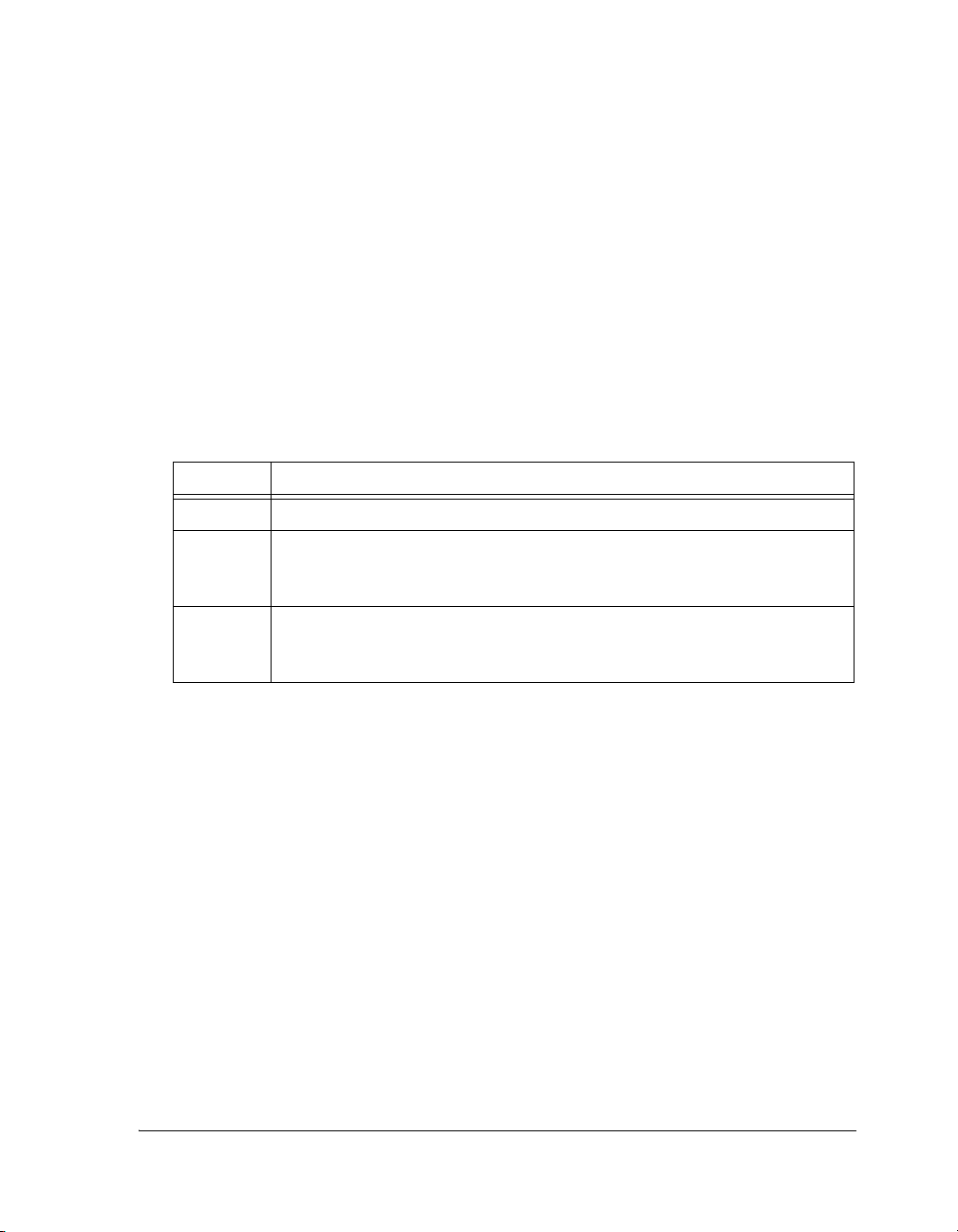
Each documentation file type is described as follows.
File Description
.CHM Help system files and manuals in Help format
.HTM or
.HTML
.PDF VisualDSP++ and processor manuals in Portable Documentation Format (PDF).
Dinkum Abridged C++ library and FlexLM network license manager software documentation. Viewing and printing the .HTML files requires a browser, such as
Internet Explorer 4.0 (or higher).
Viewing and printing the .PDF files requires a PDF reader, such as Adobe Acrobat
Reader (4.0 or higher).
Access the online documentation from the VisualDSP++ environment,
Windows® Explorer, or the Analog Devices Web site.
Accessing Documentation From VisualDSP++
From the VisualDSP++ environment:
• Access VisualDSP++ online Help from the Help menu’s Contents,
Search, and Index commands.
• Open online Help from context-sensitive user interface items (toolbar buttons, menu commands, and windows).
VisualDSP++ 4.0 Linker and Utilities Manual xxvii
Page 28

Product Information
Accessing Documentation From Windows
In addition to any shortcuts you may have constructed, there are many
ways to open VisualDSP++ online Help or the supplementary documentation from Windows.
Help system files (.CHM) are located in the Help folder of VisualDSP++
environment. The .PDF files are located in the Docs folder of your
VisualDSP++ installation CD-ROM. The Docs folder also contains the
Dinkum Abridged C++ library and the FlexLM network license manager
software documentation.
Using Windows Explorer
• Double-click the vdsp-help.chm file, which is the master Help system, to access all the other .CHM files.
• Open your VisualDSP++ installation CD-ROM and double-click
any file that is part of the VisualDSP++ documentation set.
Using the Windows Start Button
• Access VisualDSP++ online Help by clicking the Start button and
choosing Programs, Analog Devices, VisualDSP++, and
VisualDSP++ Documentation.
Accessing Documentation From the Web
Download manuals in PDF format at the following Web site:
http://www.analog.com/processors/resources/technicalLibrary/manuals
Select a processor family and book title. Download archive (.ZIP) files, one
for each manual. Use any archive management software, such as WinZip,
to decompress downloaded files.
xxviii VisualDSP++ 4.0 Linker and Utilities Manual
Page 29

Preface
Printed Manuals
For general questions regarding literature ordering, call the Literature
Center at 1-800-ANALOGD (1-800-262-5643) and follow the prompts.
VisualDSP++ Documentation Set
To purchase VisualDSP++ manuals, call 1-603-883-2430. The manuals
may be purchased only as a kit.
If you do not have an account with Analog Devices, you are referred to
Analog Devices distributors. For information on our distributors, log onto
http://www.analog.com/salesdir/continent.asp.
Hardware Tools Manuals
To purchase EZ-KIT Lite® and In-Circuit Emulator (ICE) manuals, call
1-603-883-2430. The manuals may be ordered by title or by product
number located on the back cover of each manual.
Processor Manuals
Hardware reference and instruction set reference manuals may be ordered
through the Literature Center at 1-800-ANALOGD (1-800-262-5643),
or downloaded from the Analog Devices Web site. Manuals may be
ordered by title or by product number located on the back cover of each
manual.
Data Sheets
All data sheets (preliminary and production) may be downloaded from the
Analog Devices Web site. Only production (final) data sheets (Rev. 0, A,
B, C, and so on) can be obtained from the Literature Center at
1-800-ANALOGD (1-800-262-5643); they also can be downloaded from
the Web site.
VisualDSP++ 4.0 Linker and Utilities Manual xxix
Page 30
Notation Conventions
To have a data sheet faxed to you, call the Analog Devices Faxback System
at 1-800-446-6212. Follow the prompts and a list of data sheet code
numbers will be faxed to you. If the data sheet you want is not listed,
check for it on the Web site.
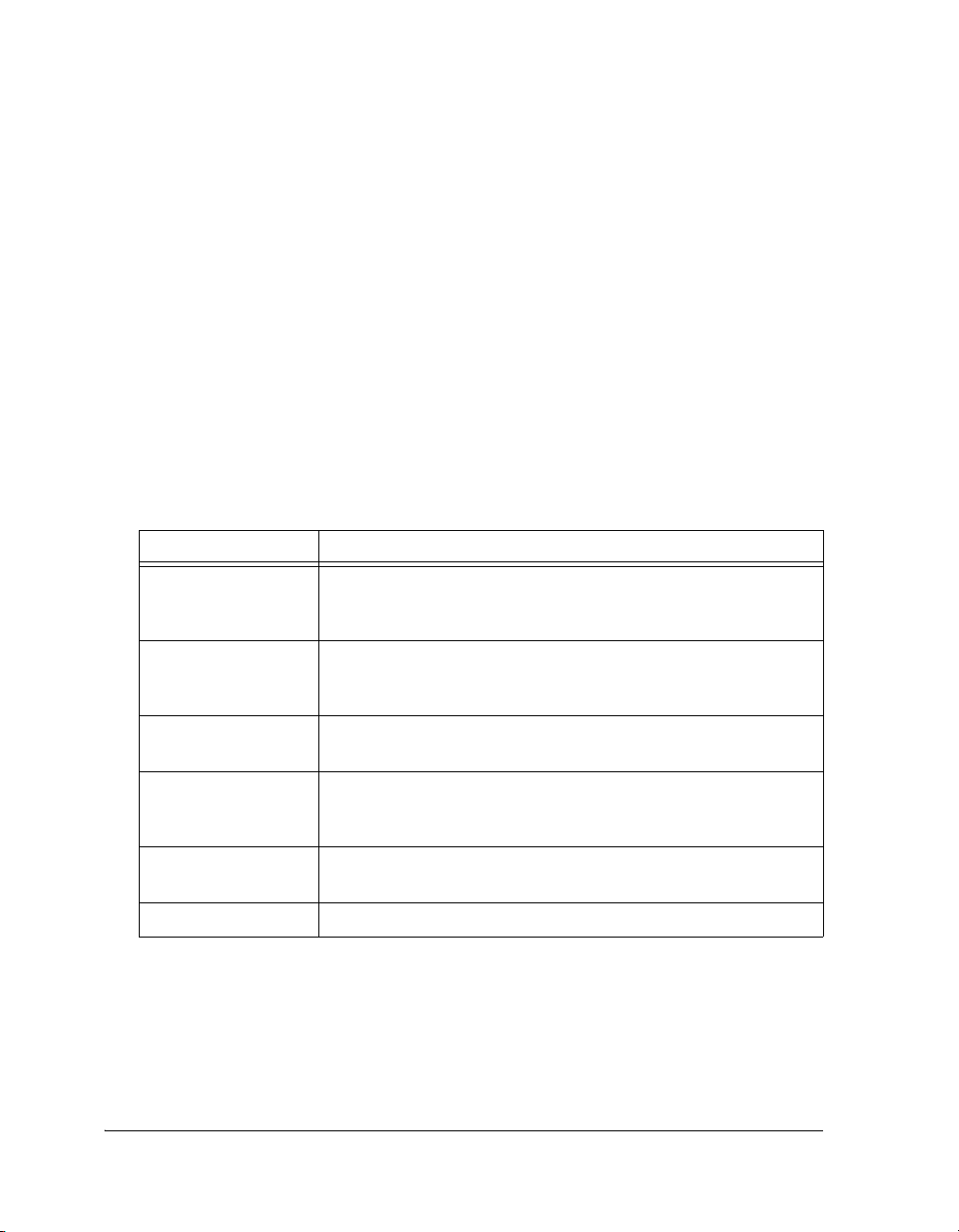
Notation Conventions
Text conventions used in this manual are identified and described as
follows.
L
Example Description
Close command
(File menu)
{this | that} Alternative required items in syntax descriptions appear within curly
[this | that] Optional items in syntax descriptions appear within brackets and sepa-
[this,…] Optional item lists in syntax descriptions appear within brackets
.SECTION Commands, directives, keywords, and feature names are in text with
filename Non-keyword placeholders appear in text with italic style format.
appear throughout this document.
Titles in reference sections indicate the location of an item within the
VisualDSP++ environment’s menu system (for example, the Close
command appears on the File menu).
brackets and separated by vertical bars; read the example as this or
that. One or the other is required.
rated by vertical bars; read the example as an optional this or that.
delimited by commas and terminated with an ellipse; read the example
as an optional comma-separated list of
letter gothic font.
this.
Additional conventions, which apply only to specific chapters, may
xxx VisualDSP++ 4.0 Linker and Utilities Manual
Page 31

Example Description
Note: For correct operation, ...
A Note provides supplementary information on a related topic. In the
L
a
[
online version of this book, the word Note appears instead of this
symbol.
Caution: Incorrect device operation may result if ...
Caution: Device damage may result if ...
A Caution identifies conditions or inappropriate usage of the product
that could lead to undesirable results or product damage. In the online
version of this book, the word Caution appears instead of this symbol.
Warn in g: Injury to device users may result if ...
A Warning identifies conditions or inappropriate usage of the product
that could lead to conditions that are potentially hazardous for devices
users. In the online version of this book, the word Wa rnin g appears
instead of this symbol.
Preface
VisualDSP++ 4.0 Linker and Utilities Manual xxxi
Page 32

Notation Conventions
xxxii VisualDSP++ 4.0 Linker and Utilities Manual
Page 33

1 INTRODUCTION
This chapter provides an overview of VisualDSP++ development tools and
their use in the [DSP] project development process.
L
This chapter includes:
The code examples in this manual have been compiled using
VisualDSP++ 4.0. The examples compiled with other versions of
VisualDSP++ may result in build errors or different output
although the highlighted algorithms stand and should continue to
stand in future releases of VisualDSP++.
• “Software Development Flow” on page 1-2
Shows how linking, loading, and splitting fit into the project development process.
• “Compiling and Assembling” on page 1-3
Shows how compiling and assembling the code fits into the project
development process.
• “Linking” on page 1-7
Shows how linking fits into the project development process.
• “Loading and Splitting” on page 1-10
Shows how loading and splitting fit into the project development
process.
VisualDSP++ 4.0 Linker and Utilities Manual 1-1
Page 34

Software Development Flow
Software Development Flow
The majority of this manual describes linking, a critical stage in the
program development process for embedded applications.
The linker tool (linker.exe) consumes object and library files to produce
executable files, which can be loaded onto a simulator or target processor.
The linker also produces map files and other output that contain information used by the debugger. Debug information is embedded in the
executable file.
After running the linker, you test the output with a simulator or emulator.
Refer to the VisualDSP++ 4.0 User’s Guide and online Help for information about debugging.
Finally, you process the debugged executable file(s) through the loader or
splitter to create output for use on the actual processor. The output file
may reside on another processor (host) or may be burned into a PROM.
The VisualDSP++ 4.0 Loader Manual describes loader/splitter functionality for the target processors.
The processor software development flow can be split into three phases:
1. Compiling and Assembling – Input source files C (.C), C++ (.CPP),
and assembly (.ASM) yield object files (.DOJ)
2. Linking – Under the direction of the Linker Description File
.LDF), a linker command line, and VisualDSP++ Project Options
(
dialog box settings, the linker utility consumes object files (.DOJ)
to yield an executable (.DXE) file. If specified, shared memory (.SM)
and overlay (
3. Loading or Splitting – The executable (.DXE) file, as well as shared
memory (.SM) and overlay (.OVL) files, are processed to yield
output file(s). For TigerSHARC and Blackfin processors, these are
boot-loadable (LDR) files or non-bootable PROM image files, which
execute from the processor’s external memory.
1-2 VisualDSP++ 4.0 Linker and Utilities Manual
.OVL) files are also produced.
Page 35

Introduction
Compiling and Assembling
The process starts with source files written in C, C++, or assembly. The
compiler (or a code developer who writes assembly code) organizes each
distinct sequence of instructions or data into named sections, which
become the main components acted upon by the linker.
Inputs – C/C++ and Assembly Sources
The first step towards producing an executable file is to compile or assemble C, C++, or assembly source files into object files. The VisualDSP++
development software assigns a .DOJ extension to object files (Figure 1-1).
Figure 1-1. Compiling and Assembling
Object files produced by the compiler (via the assembler) and by the
assembler itself consist of input sections. Each input section contains
a particular type of compiled/assembled source code. For example, an
input section may consist of program opcodes or data, such as variables
of various widths.
Some input sections may contain information to enable source-level
debugging and other VisualDSP++ features. The linker maps each input
section (via a corresponding output section in the executable) to a memory
segment, a contiguous range of memory addresses on the target system.
VisualDSP++ 4.0 Linker and Utilities Manual 1-3
Page 36

Compiling and Assembling
Each input section in the .LDF file requires a unique name, as specified in
the source code. Depending on whether the source is C, C++, or assembly,
different conventions are used to name an input section (see Chapter 3,
“Linker Description File”).
Input Section Directives in Assembly Code
A .SECTION directive defines a section in assembly source. This directive
must precede its code or data.
SHARC Code Example
.SECTION/DM asmdata; // Declares section asmdata
.VAR input[3]; // Declares data buffer in asmdata
.SECTION/PM asmcode; // Declares section asmcode
R0 = 0x1234; // Three lines of code in asmcode
R1 = 0x4567;
R3 = R1 + R2;
In this example, the /dm asmdata input section contains the array input,
and the /pm asmcode input section contains the three line of code.
Blackfin Code Example
.SECTION Library_Code_Space; /* Section Directive */
.global _abs;
_abs:
R0 = ABS R0; /* Take absolute value of input */
RTS;
_abc.end
In this example, the assembler places the global symbol/label _abs and the
code after the label into the input section Library_Code_Space, as it processes this file into object code.
1-4 VisualDSP++ 4.0 Linker and Utilities Manual
Page 37

Introduction
Input Section Directives in C/C++ Source Files
Typically, C/C++ code does not specify an input section name, so the
compiler uses a default name. By default, the input section names program
(for code) and data1 (for data) are used. Additional input section names
are defined in .LDF files (see “Specifying the Memory Map” on page 2-17
for more information on memory mapping).
In C/C++ source files, you can use the optional section(“name”) C language extension to define sections.
Example 1
While processing the following code, the compiler stores the temp variable
in the ext_data input section of the .DOJ file and also stores the code generated from func1 in an input section named extern.
...
section ("ext_data") int temp; /* Section directive */
section ("extern") void func1(void) { int x = 1; }
...
Example 2
In the following example, section ("extern") is optional. Note the new
function (funct2) does not require section ("extern"). For more information on LDF sections, refer to “Specifying the Memory Map” on
page 2-17.
section ("ext_data") int temp;
section ("extern") void func1(void) { int x = 1; }
int func2(void) { return 13; } /* New */
VisualDSP++ 4.0 Linker and Utilities Manual 1-5
Page 38

Compiling and Assembling
For information on compiler default section names, refer to the
VisualDSP++ 4.0 C/C++ Compiler and Library Manual for appropriate
target processors and “Placing Code on the Target” on page 2-40.
L
Identify the difference between input section names, output section names, and memory segment names because these types of
names appear in the .LDF file. Usually, default names are used.
However, in some situations you may want to use non-default
names. One such situation is when various functions or variables
(in the same source file) are to be placed into different memory
segments.
1-6 VisualDSP++ 4.0 Linker and Utilities Manual
Page 39

Introduction
Linking
After you have (compiled and) assembled source files into object files, use
the linker to combine the object files into an executable file. By default,
the development software gives executable files a .DXE extension
(Figure 1-2).
Figure 1-2. Linking Diagram
Linking enables your code to run efficiently in the target environment.
Linking is described in detail in Chapter 2, “Linker”.
L
VisualDSP++ 4.0 Linker and Utilities Manual 1-7
When developing a new project, use the Expert Linker to generate
the project’s
information.
.LDF file. See Chapter 4, “Expert Linker” for more
Page 40

Linking
Linker and Assembler Preprocessor
The linker and assembler preprocessor program (pp.exe) evaluates and
processes preprocessor commands in source files. With these commands,
you direct the preprocessor to define macros and symbolic constants,
include header files, test for errors, and control conditional assembly and
compilation.
The pp preprocessor is run by the assembler or linker from the operating
system’s command line or within the VisualDSP++ environment. These
tools accept and pass this command information to the preprocessor. The
preprocessor can also operate from the command line using its own command-line switches.
Assembler/Linker Preprocessor treats the character “.” as part of an
identifier
The preprocessor matches the assembler which uses “.” as part of assembler directives and as a legal character in labels. This behavior does create a
possible problem for users that have written preprocessor macros that rely
on identifiers to break when encountering the “.” character, usually seen
when processing register names. For example,
#define Loadd(reg, val) \
reg.l = val;\
reg.h = val;
The above example would not work in VisualDSP++ 4.0 becauseVisualDSP++ 4.0 does not provide any replacement since
reg is not parsed as a
separate identifier. The macro has to be rewritten using the operator ##
such as:
#define Loadd(reg, val)\
reg ## .l = val;\
reg ## .h = val;
1-8 VisualDSP++ 4.0 Linker and Utilities Manual
Page 41

Introduction
L
L
The preprocessor supports ANSI C standard preprocessing with
extensions but differs from the ANSI C standard preprocessor in
several ways. For more information on the pp preprocessor, see the
VisualDSP++ 4.0 Assembler and Preprocessor Manual.
The compiler has it own preprocessor that allows you to use preprocessor commands within your C/C++ source. The compiler
preprocessor automatically runs before the compiler. For more
information, see the VisualDSP++ 4.0 C/C++ Compiler and Library
Manual for the appropriate target archtecture.
VisualDSP++ 4.0 Linker and Utilities Manual 1-9
Page 42

Loading and Splitting
Loading and Splitting
After debugging the .DXE file, you process it through a loader or splitter to
create output files used by the actual processor. The file(s) may reside on
another processor (host) or may be burned into a PROM.
For more information, refer to the VisualDSP++ 4.0 Loader Manual
which provides detailed descriptions of the processes and options used to
generate boot-loadable .LDR (loader) files for the approprate target processors. This manual also describes the splitting utility, which (when used)
creates the non-bootloadable files that execute from the processor’s external memory.
In general:
• The SHARC ADSP-2106x/ADSP-21160 processors use the loader
(elfloader.exe) to yield a boot-loadable image (.LDR file), which
resides in memory external to the processor (PROM or host processor). Use the splitter utility (elfspl21k.exe) to generate
non-bootable PROM image files, which execute from the processor’s external memory (often used with the ADSP-21065L
processors).
• The SHARC ADSP-2116x/2126x/2136x processors use the loader
(elfloader.exe) to yield a boot-loadable image (.LDR file), which
transported to (and run from) processor memory. To make a loadable file, the loader processes data from a boot-kernel file (.
and one or more other executable files (.
DXE).
DXE)
• The TigerSHARC processors use the loader (elfloader.exe) to
yield a boot-loadable image (
.LDR file), which transported to (and
run from) processor memory. To make a loadable file, the loader
processes data from a boot-kernel file (.
executable files (.
DXE).
DXE) and one or more other
1-10 VisualDSP++ 4.0 Linker and Utilities Manual
Page 43

Introduction
• Both TigerSHARC and SHARC processors use the splitter utility
(elfspl21k.exe) to generate non-bootable PROM image files,
which execute from the processor’s external memory.
• The Blackfin processors use the loader (elfloader.exe) to yield a
boot-loadable image (.LDR file), which resides in memory external
to the processor (PROM or host processor. To make a loadable file,
the loader processes data from a boot-kernel file (.DXE) and one or
more other executable files (.DXE).
Figure 1-3 shows a simple application of the loader. In this example, the
loader’s input is a single executable (.DXE) file. The loader can accommodate up to two .DXE files as input plus one boot kernel file (.DXE).
Figure 1-3. Loading Diagram
VisualDSP++ 4.0 Linker and Utilities Manual 1-11
Page 44

Loading and Splitting
For example, when a TigerSHARC processor is reset, the boot kernel portion of the image is transferred to the processor’s core. Then, the
instruction and data portion of the image are loaded into the processor’s
internal RAM (as shown in Figure 1-4) by the boot kernel.
Figure 1-4. Booting from a Bootloadable (.LDR) File
VisualDSP++ includes boot kernel files (.DXE), which are automatically
used when you run the loader. You can also customize boot kernel source
files (included with VisualDSP++) by modifying and rebuilding them.
Figure 1-5 shows how multiple input files—in this case, two executable
(.DXE) files, a shared memory (.SM) file, and overlay (.OVL) files—are
consumed by the loader to create a single image file (
illustrate the generation of a loader file for a multiprocessor architecture.
L
This example has two executable files that share memory. Overlays are also
included. The resulting output is a compilation of all the inputs.
1-12 VisualDSP++ 4.0 Linker and Utilities Manual
The .SM and .OVL files must reside in the same directory that contains the input
your system does not use shared memory or overlays, .SM and .OVL
files are not required.
.DXE file(s) or in the current working directory. If
.LDR). This example
Page 45

Introduction
Figure 1-5. Input Files for a Multiprocessor System
VisualDSP++ 4.0 Linker and Utilities Manual 1-13
Page 46

Loading and Splitting
1-14 VisualDSP++ 4.0 Linker and Utilities Manual
Page 47

2LINKER
Linking assigns code and data to processor memory. For a simple single
processor architecture, a single .DXE file is generated. A single invocation
of the linker may create multiple executable (.DXE) files for multiprocessor
(MP) architectures. Linking can also produce a shared memory (.SM) file
for an MP system. A large executable file can be split into a smaller executable file and overlays (.OVL) files, which contain code that is called in
(swapped into internal processor memory) as needed. The linker
(linker.exe) performs this task.
You can run the linker from a command line or from the VisualDSP++
Integrated Development and Debugging Environment (IDDE).
You can load the link output into the VisualDSP++ debugger for simulation, testing, and profiling.
This chapter includes:
• “Linker Operation” on page 2-2
• “Linking Environment” on page 2-6
• “Link Target Description” on page 2-16
• “Linker Command-Line Reference” on page 2-47
VisualDSP++ 4.0 Linker and Utilities Manual 2-1
Page 48

Linker Operation
Linker Operation
Figure 2-1 illustrates a basic linking operation. The figure shows several
object (.DOJ) files being linked into a single executable (.DXE) file. The
Linker Description File (.LDF) directs the linking process.
Figure 2-1. Linking Object Files to Produce an Executable File
L
In a multiprocessor system, a .DXE file for each processor is generated. For
example, for a two-processor system, you must generate two
The processors in a multiprocessor architecture may share memory. When
directed by statements in the
ory (.SM) executable file, whose code is used by multiple processors.
Overlay files, another linker output, support applications that require
more program instructions and data than the processor’s internal memory
can accommodate. Refer to “Memory Management Using Overlays” on
page 5-4 for more information.
2-2 VisualDSP++ 4.0 Linker and Utilities Manual
When developing a new project, use the Expert Linker to generate
the project’s .LDF file. See Chapter 4, “Expert Linker” for more
information.
.DXE files.
.LDF file, the linker produce a shared mem-
Page 49

Linker
Similar to object files, executable files are partitioned into output sections
with unique names. Output sections are defined by the Executable and
Linking Format (ELF) file standard to which VisualDSP++ conforms.
L
The executable file(s) (.DXE) and auxiliary files (.SM and .OVL) are not
loaded into the processor or burned onto an EPROM. These files are used
to debug the system.
The executable’s input section names and output section names
occupy different namespaces. Because the namespaces are independent, the same section names may be used. The linker uses input
section names as labels to locate corresponding input sections
within object files.
Directing Linker Operation
Linker operations are directed by these options and commands:
• Linker (linker.exe) command-line switches (options). Refer to
“Linker Command-Line Reference” on page 2-47.
• Settings (options) on the Link page of the Project Options dialog
box. See “Project Builds” on page 2-6.
• LDF commands. Refer to “LDF Commands” on page 3-29 for a
detailed description.
Linker options control how the linker processes object files and library
files. These options specify various criteria such as search directories, map
file output, and dead code elimination. You select linker options via linker
command-line switches or by settings on the Link page of the Project
Options dialog box within the VisualDSP++ environment.
LDF commands in a Linker Description File (.LDF) define the target
memory map and the placement of program sections within processor
memory. The text of these commands provides the information needed to
link your code.
VisualDSP++ 4.0 Linker and Utilities Manual 2-3
Page 50

Linker Operation
L
Using directives in the .LDF file, the linker:
The VisualDSP++ Project window displays the .LDF file as a source
file, though the file provides linker command input.
• Reads input sections in the object files and maps them to output
sections in the executable file. More than one input section may be
placed in an output section.
• Maps each output section in the executable to a memory segment,
a contiguous range of memory addresses on the target processor.
More than one output section may be placed in a single memory
segment.
Linking Process Rules
The linking process observes these rules:
• Each source file produces one object file.
• Source files may specify one or more input sections as destinations
for compiled/assembled object(s).
• The compiler and assembler produce object code with labels that
direct one or more portions to particular output sections.
• As directed by the .LDF file, the linker maps each input section
in the object code to an output section in the
• As directed by the .LDF file, the linker maps each output section
to a memory segment.
• Each input section may contain multiple code items, but a code
item may appear in one input section only.
• More than one input section may be placed in an output section.
• Each memory segment must have a specified width.
2-4 VisualDSP++ 4.0 Linker and Utilities Manual
.DXE file.
Page 51

• Contiguous addresses on different-width hardware must reside in
different memory segments.
• More than one output section may map to a memory segment if
the output sections fit completely within the memory segment.
Linker Description File Overview
Whether you are linking C/C++ functions or assembly routines, the mechanism is the same. After converting the source files into object files, the
linker uses directives in an
able (.DXE) file, which may be loaded into a simulator for testing.
.LDF file to combine the objects into an execut-
Linker
L
Each project must include one .LDF file that specifies the linking process
by defining the target memory and mapping the code and data into that
memory. You can write your own .LDF file, or you can modify an existing
file; modification is often the easier alternative when there are few changes
in your system’s hardware or software. VisualDSP++ provides an .LDF file
that supports the default mapping of each processor type.
L
Similar to an object (.DOJ) file, an executable (.DXE) file consists of
different segments, called output sections. Input section names are independent of output section names. Because they exist in different
namespaces, input section names can be the same as output section names.
Refer to Chapter 3, “Linker Description File” for further information.
Executable file structure conforms to the Executable and Linkable
Format (ELF) standard.
When developing a new project, use the Expert Linker to generate
the project’s .LDF file, as described in Chapter 4, “Expert Linker”.
VisualDSP++ 4.0 Linker and Utilities Manual 2-5
Page 52

Linking Environment
Linking Environment
The linking environment refers to Windows command-prompt windows
and the VisualDSP++ IDDE. At a minimum, run development tools (such
as the linker) via a command line and view output in standard output.
VisualDSP++ provides an environment that simplifies the processor program build process. From VisualDSP++, you specify build options from
the Project Options dialog box and modify files, including the Linker
Description File (.LDF). The Project Options dialog box’s Type option
allows you to choose whether to build a library (.DLB) file, an executable
(.DXE) file, or an image file (.LDR or others). Error and warning messages
appear in the Output window.
Project Builds
The linker runs from an operating system command line, issued from the
VisualDSP++ IDDE, or a command prompt window. Figure 2-2 shows
the VisualDSP++ environment with the Project window and an .LDF file
open in an Editor window.
The VisualDSP++ IDDE provides an intuitive interface for processor programming. When you open VisualDSP++, a work area contains everything
needed to build, manage, and debug a DSP project. You can easily create
or edit an .
on the target.
L
2-6 VisualDSP++ 4.0 Linker and Utilities Manual
LDF file, which maps code or data to specific memory segments
For information about the VisualDSP++ environment, refer to the
VisualDSP++ User’s Guide for the appropriate target architecture or
online Help. Online Help provides powerful search capabilities. To
obtain information on a code item, parameter, or error, select text
in an VisualDSP++ IDDE Editor window or Output window and
press the keyboard’s F1 key.
Page 53

Linker
Figure 2-2. VisualDSP++ Environment
Within VisualDSP++, specify tool settings for project builds. Use the
Project menu to open Project Options dialog box.
Figure 2-3, Figure 2-4, and Figure 2-5 show the project option selections
for SHARC, TigerSHARC, and Blackfin processors, respectively.
These dialog boxes allow you to select the target processor, type and and
name of the executable file, as well as VisualDSP++ tools available for use
with the selected processor.
When using the VisualDSP++ IDDE, use the Link option from the
Project Options dialog box (Figure 2-6) to select and/or set linker func-
tional options.
VisualDSP++ 4.0 Linker and Utilities Manual 2-7
Page 54

Linking Environment
Figure 2-3. Project Options Dialog Box (SHARC Processors)
Figure 2-4. Project Options Dialog Box (TigerSHARC Processors)
2-8 VisualDSP++ 4.0 Linker and Utilities Manual
Page 55

Linker
Figure 2-5. Project Options Dialog Box (Blackfin Processors)
There are four subpages you can access—General, LDF Preprocessing,
Elimination, and Processor. Almost every setting option has a corresponding compiler command-line switch described in “Linker
Command-Line Switches” on page 2-51.
The Additional options field in each sub-page is used to enter the appropriate file names and options that do not have corresponding controls on
the Link sub-page but are available as compiler switches.
Due to different processor architectures, the processors may provide different Link tab selection options. For example, Figure 2-7 shows Blackfin
processor options page.
Figure 2-8 shows SHARC processor options page.
VisualDSP++ 4.0 Linker and Utilities Manual 2-9
Page 56

Linking Environment
Figure 2-6. Project Options – Link Page
2-10 VisualDSP++ 4.0 Linker and Utilities Manual
Page 57

Linker
Figure 2-7. Project Options – Link (Processor) Blackfin Page
VisualDSP++ 4.0 Linker and Utilities Manual 2-11
Page 58

Linking Environment
Figure 2-8. Project Options – Link (Processor) SHARC Page
2-12 VisualDSP++ 4.0 Linker and Utilities Manual
Page 59

Figure 2-9 shows TigerSHARC processor options page.
Linker
Figure 2-9. Project Options – Link (Processor) TigerSHARC Page
Use the VisualDSP++ context-sensitive online Help for each target architecture to obtain information on linker options you can specify in
VisualDSP++. To do that, click on the ? button and then click in a field or
box you need information about.
VisualDSP++ 4.0 Linker and Utilities Manual 2-13
Page 60

Linking Environment
Expert Linker
The VisualDSP++ IDDE features an interactive tool, Expert Linker,
to map code or data to specific memory segments. When developing
a new project, use the Expert Linker to generate the .LDF file.
Expert Linker graphically displays the .LDF information (object files, LDF
macros, libraries, and a target memory description). With Expert Linker,
use drag-and-drop operations to arrange the object files in a graphical
memory mapping representation. When you are satisfied with the memory
layout, generate the executable (
Figure 2-10 shows the Expert Linker window, which comprises two panes:
Input Sections and Memory Map (output sections). Refer to Chapter 4,
“Expert Linker”, for detailed information.
.DXE) file.
Figure 2-10. Expert Linker Window
2-14 VisualDSP++ 4.0 Linker and Utilities Manual
Page 61

Linker Warning and Error Messages
Linker messages are written to the VisualDSP++ Output window
(standard output when the linker is run from a command line). Messages
describe problems the linker encountered while processing the .LDF file.
Warnings indicate processing errors that do not prevent the linker from
producing a valid output file, such as unused symbols in your code. Errors
are issued when the linker encounters situations that prevent the production of a valid output file.
Typically, these messages include the name of the .LDF file, the line number containing the message, a six-character code, and a brief description of
the condition.
Example
>linker -proc ADSP-unknown a.doj
Linker
[Error li1010] The processor ‘ADSP-unknown’ is
unknown or unsuppported.
Interpreting Linker Messages
Within VisualDSP++, the Output window’s Build tab displays project
build status and error messages. In most cases, double-clicking a message
displays the line in the source file causing the problem. You can access
descriptions of linker messages from VisualDSP++ online Help by selecting a six-character code (for example, li1010) and pressing the F1 key.
Some build errors, such as a reference to an undefined symbol, do not correlate directly to source files. These errors often stem from omissions in
the .LDF file.
For example, if an input section from the object file is not placed by the
.
LDF file, a cross-reference error occurs at every object that refers to labels
in the missing section. Fix this problem by reviewing the .
LDF file and
specifying all sections that need placement. For more information, refer to
the VisualDSP++ 4.0 User’s Manual or online Help.
VisualDSP++ 4.0 Linker and Utilities Manual 2-15
Page 62

Link Target Description
Link Target Description
Before defining the system’s memory and program placement with linker
commands, analyze the target system to ensure you can describe the target
in terms the linker can process. Then, produce an .LDF file for your project
to specify these system attributes:
• Physical memory map
• Program placement within the system’s memory map
L
Be sure to understand the processor’s memory architecture, which is
described in the appropriate processor’s hardware reference manual and in
its data sheet.
This section contains:
If the project does not include an .LDF file, the linker uses a default
.LDF file for the processor that matches the -proc <processor>
switch on the linker’s command line (or the Processor selection
specified on the Project page of the Project Options dialog box in
the VisualDSP++ IDDE).
• “Representing Memory Architecture” on page 2-17
• “Specifying the Memory Map” on page 2-17
• “Placing Code on the Target” on page 2-40
• “Profile-Guided Optimization Support” on page 2-45
• “Passing Arguments for Simulation or Emulation” on page 2-46
2-16 VisualDSP++ 4.0 Linker and Utilities Manual
Page 63

Representing Memory Architecture
The .LDF file’s MEMORY{} command is used to represent the memory architecture of your processor system. The linker uses this information to place
the executable file into the system’s memory.
Perform the following tasks to write a MEMORY{} command:
• Memory Usage. List the ways your program uses memory in your
system. Typical uses for memory segments include interrupt tables,
initialization data, program code, data, heap space, and stack space.
Refer to “Specifying the Memory Map” on page 2-17.
• Memory Characteristics. List the types of memory in your processor system and the address ranges and word width associated with
each memory type. Memory type is defined as RAM or ROM.
• MEMORY{} Command. Construct a MEMORY{} command to combine the information from the previous two lists and to declare
your system’s memory segments.
Linker
For complete information, refer to “MEMORY{}” on page 3-35.
Specifying the Memory Map
A DSP program must conform to the constraints imposed by the processor’s data path (bus) widths and addressing capabilities. The following
information describes an
specifies several memory segments that support the
as shown in “SECTIONS{}” on page 3-48.
The three topics are important when allocating memory:
• “Memory Usage and Default Memory Sections” on page 2-18
• “Memory Characteristics Overview” on page 2-31
• “Linker MEMORY{} Command in .LDF File” on page 2-38
VisualDSP++ 4.0 Linker and Utilities Manual 2-17
.LDF file for a hypothetical project. This file
SECTIONS{} command,
Page 64

Link Target Description
Memory Usage and Default Memory Sections
Input section names are generated automatically by the compiler or are
specified in the assembly source code. The .LDF file defines memory section names and output section names. The default .LDF file handles all
compiler-generated input sections (refer to the “Input Section” column in
Table 2-1, Table 2-2, and Table 2-3). The produced .DXE file has a corre-
sponding output section for each input section. Although programmers
typically do not use output section labels, the labels are used by downstream tools.
Use the ELF file dumper utility (elfdump.exe) to dump contents of an
output section (for example, data1) of an executable file. See “elfdump –
ELF File Dumper” on page B-1 for information about this utility.
The following sections show how input sections, output sections, and
memory segments correspond in the default .LDF files for appropriate target processor architectures.
L
Typical uses for memory segments include interrupt tables, initialization
data, program code, data, heap space, and stack space, etc. For detailed
processor-specific information, refer to:
2-18 VisualDSP++ 4.0 Linker and Utilities Manual
Refer to your processor’s default .LDF file and to the hardware reference manual for details.
• “Default Memory Sections for SHARC Processors”
• “Default Memory Sections for TigerSHARC Processors”
• “Default Memory Sections for Blackfin Processors”
• “Special “Table” Memory Sections”
Page 65

Default Memory Sections for SHARC Processors
Table 2-1 shows section mapping in the default .LDF file for ADSP-21161
processor (as an example for SHARC processors)
Table 2-1. Section Mapping in the Default SHARC LDF
Input Section Output Section Memory Section
seg_pmco dxe_pmco seg_pmco
seg_dmda dxe_dmda seg_dmda
seg_pmda dxe_pmda seg_pmda
heap dxe_heap seg_heap
seg_stak dxe_stak seg_stak
sec_rth dxe_rth seg_rth
seg_init seg_init seg_init
Linker
seg_init_code seg_init_code seg_init_code
seg_argv seg_argv seg_argv
seg_ctdm seg_ctdm seg_ctdm
seg_vtbl seg_vtbl seg_vtbl
There are several input/memory sections used in the default .LDF files for
ADSP-210xx/211xx/212xx/213xx processors, which must be present in
user’s own
.LDF files. These sections are described in detail below.
seg_rth
This section contains the interrupt vector table (by default, this is located
in the start-up file (for example, 060_hdr.doj).
VisualDSP++ 4.0 Linker and Utilities Manual 2-19
Page 66

Link Target Description
seg_init
This section contains location and size information about the stack and
heap; also contains compressed data created by the memory initialization
tool (see “-meminit” on page 2-62 for more information).
seg_int_code
Code that modifies interrupt latch registers must not be executed from
external memory. To minimize the impact of this restriction, the library
functions that modify the latch registers are located in the seg_init_code
section, which should be located in internal memory.
seg_pmco
This section is the default location for program code.
seg_pmda
This section is the default location for global program data that is qualified with the “pm” keyword. For example,
int pm xyz[100]; // Located in seg_pmda
seg_argv
This section contains the command-line arguments that are used as part of
Profile-Guided Optimization (PGO).
seg_ctdm
This section (see also seg_ctdml on page 2-21) contains the addresses of
constructors that are called before the start of a C++ program (such as constructors for global and static objects). This section must be terminated
with the symbol “___ctor_NULL_marker” (the default .ldf files ensure
this). It is required if compiling with C++ code.
2-20 VisualDSP++ 4.0 Linker and Utilities Manual
Page 67

seg_dmda
This section is the default location for global data, and also for data that is
qualified with the “dm” keyword. For example,
int abc[100]; // Located in seg_dmda
int dm def[100]; // Located in seg_dmda
seg_heap
This section is the area from which memory allocation functions and
operators (new, malloc(), and so on) allocate memory.
seg_stak
This section is the area where the run-time stack is located. Local variables, function parameters, and so on are stored here.
Linker
seg_vtbl
This section contains C++ virtual function tables. The default .LDF files
place the virtual function tables into the default data memory area but this
can be re-mapped as required. You can also direct the compiler to use a
different section for C+ virtual function tables, by using the -section
compiler switch.
Other Memory Sections
The compiler and libraries also use other data sections that are linked into
one of the above memory sections. These data sections include:
seg_ctdml
The symbol “___ctor_NULL_marker” (located in the C++ run-time library)
marks the end of the list of global and static constructors and is placed in
this data section. The linker ensures that the contents of this data section
are the last items in
seg_ctdm.
VisualDSP++ 4.0 Linker and Utilities Manual 2-21
Page 68

Link Target Description
.gdt .gdtl .frt .frtl .cht .chtl .edt .edtl
These data sections are used to hold data used during the handling of
exceptions. The linker places the contents of these data sections in
seg_dmda. See “Special “Table” Memory Sections” on page 2-30.
Default Memory Sections for TigerSHARC Processors
Table 2-2 shows section mapping in the default .LDF file for ADSP-TS101
processor (as an example for TigerSHARC processors)
Table 2-2. Section Mapping in the Default TigerSHARC LDF
Input Section Output Section Memory Section
program code M0Code
data1 data1 M1Data
data2 data2 M2Data
heaptab heaptab M1Data
mem_argv mem_argv M1Data
bsz_init bsz M1Data
bsz bsz_init M1Data
jstackseg M1Stack
kstackseg M2Stack
defheapseg M1Heap
ctor ctor M1Data
ctor0 ctor M1Data
ctor1 ctor M1Data
ctor2 ctor M1Data
ctor3 ctor M1Data
2-22 VisualDSP++ 4.0 Linker and Utilities Manual
Page 69

Table 2-2. Section Mapping in the Default TigerSHARC LDF (Cont’d)
Input Section Output Section Memory Section
ctor4 ctor M1Data
vtbl vtbl vtbl
There are several input/memory sections used in the default .LDF files for
ADSP-TSxxx processors, which must be present in user’s own .LDF files.
These sections are described in detail below.
program
This section is the default location for program code.
data1
This section is the default location for global program data.
Linker
data2
This section is the default location for global program data specified with
the pm memory qualifier.
mem_argv
This section contains the command-line arguments that are used as part of
Profile-Guided Optimization (PGO).
ctor
This section contains the addresses of constructors that are called before
the start of a C++ program (such as constructors for global and static
objects). This section must be terminated with the symbol
“___ctor_NULL_marker” (the default .ldf files ensure this). It is required if
compiling with C++ code.
VisualDSP++ 4.0 Linker and Utilities Manual 2-23
Page 70

Link Target Description
When all ctor sections are merged, they form a table containing a list of
all constructors for all global C++ objects. The table is only used at startup
and can be placed in ROM. When linking, it is important that all ctor
sections are merged in sequence (no other sections in between) and the
run-time library or the VDK run-time library is placed with the first ctor
section. Note that the default LDF’s “___ctor_NULL_marker” symbol is
placed in a section named “ctorl” which must the the last of the ctor sections to be used as input. The final letter in this name is a lower-case “L”.
heaptab
This section is the area from which memory allocation functions and
operators (new, malloc(), etc.) allocate memory.
bsz
This section is a BSS-style section for global zero-initialized data.
bsz_init
This section contains run-time initialization data (see “-meminit” on
page 2-62 for more information).
M1Stack
This section is the area where the run-time stack is located. Local variables, function parameters, and so on are stored here.
M2Stack
This section is the second area where the run-time stack is located.
M1Heap
This section is the area where the heap is located. Dynamically allocated
data is placed here.
2-24 VisualDSP++ 4.0 Linker and Utilities Manual
Page 71

vtbl
This section contains C++ virtual function tables. The default .LDF files
place the virtual function tables into the default data memory area but this
can be re-mapped as required. You can also direct the compiler to use a
different section for C+ virtual function tables, by using the -section
compiler switch.
Default Memory Sections for Blackfin Processors
Table 2-2 shows section mapping in the default .LDF file for ADSP-BF535
processor (as an example for Blackfin processors)
Table 2-3. Section Mapping in the Default ADSP-BF535 LDF
Input Section Output Section Memory Section
program program MEM_PROGRAM
Linker
data1 data1 MEM_PROGRAM
cplb_code cplb_code MEM_PROGRAM
L1_code L1_code MEM_L1_CODE
constdata constdata MEM_PROGRAM
cplb_data cplb_data MEM_PROGRAM
L1_DATA_A L1_DATA_A MEM_L1_DATA_A
L1_DATA_B L1_DATA_B MEM_L1_DATA_A
voldata voldata MEM_PROGRAM
bsz bsz MEM_L1_CODE
bsz_init bsz_init MEM_PROGRAM
heap heap MEM_HEAP
stack stack MEM_STACK
ctor program MEM_PROGRAM
argv argv MEM_ARGV
VisualDSP++ 4.0 Linker and Utilities Manual 2-25
Page 72

Link Target Description
Table 2-3. Section Mapping in the Default ADSP-BF535 LDF (Cont’d)
Input Section Output Section Memory Section
noncache_code noncache_code noncache_code
sdram sdram MEM_SDRAM
vtbl sdram vtbl
L
There are several input/memory sections used in the default .LDF files for
ADSP-BFxxx processors, which must be present in user’s own .LDF files.
These sections are described in detail below.
program
This section is the default location for program code. Code in this section
is mapped into L1 Instruction memory if possible, but will spill into
slower memory if there is not enough space.
data1
This section is the default location for global program data.
cplb_code
This section stores the run-time library’s CPLB management routines. It
is usually mapped into L1 Instruction SRAM. In particular, if
CPLB-replacement is a possibility, this section must be mapped to memory that is guaranteed to always available; this means that it must be
addressed by a locked CPLB.
For Blackfin processors, you can modify your .LDF file to place
objects into L1 memories when they are configured as SRAM.
2-26 VisualDSP++ 4.0 Linker and Utilities Manual
Page 73

constdata
This section is used for global data which is declared as constant, and for
literal constants such as strings and array initializers. The compiler’s
default behavior is to assume that “const” data remains constant, and
therefore can be mapped into read-only memory (although the default
LDFs do not do this). Refer to the -const-read-write switch in the
VisualDSP++ 4.0 C/C++ Compiler and Library Manual for Blackfin Processors for more details.
cplb_data
This section stores CPLB configuration tables In particular, the cplbtabx.doj files (where x indicates the target) mapped by the LDFs are
placed into this section. It must be mapped to a data area that is always
available. If CPLB replacement is a possibility, this section must be
mapped into memory that is covered by a locked CPLB.
Linker
L1_DATA_A
This section is used to allow data to be mapped explicitly into L1 Data A
SRAM using the SECTION directive. By default, the compiler does not generate data here. This section is analogous to L1_code.
L1_DATA_B
This section is similar to L1_DATA_A, except that it is used to map data into
L1 Data B SRAM.
voldata
This section is used for data that may change due to external influences
(such as DMA), and should not be placed into cached data areas.
VisualDSP++ 4.0 Linker and Utilities Manual 2-27
Page 74

Link Target Description
argv
This section contains the command-line arguments that are used as part of
Profile-Guided Optimization (PGO).
ctor
This section contains the addresses of constructors that are called before
the start of a C++ program (such as constructors for global and static
objects). This section must be terminated with the symbol
“___ctor_NULL_marker” (default .LDF files ensure this). It is required if
compiling with C++ code.
When all ctor sections are merged, they form a table containing a list of
all constructors for all global C++ objects. The table is only used at startup
and can be placed in ROM. When linking, it is important that all ctor
sections are merged in sequence (no other sections in between) and the
run-time library or the VDK run-time library is placed with the first ctor
section. Note that the default LDF’s “___ctor_NULL_marker” symbol is
placed in a section named “ctorl” which must the the last of the ctor sections to be used as input. The final letter in this name is a lower-case “L”.
bsz
This section is a BSS-style section for global zero-initialized data. This section does not actually contain data; it is zero-filled upon loading via the
VisualDSP++ IDDE, or when processed by the loader.
bsz_init
This section contains run-time initialization data (see “-meminit” on
page 2-62 for more information). It is expected that this section is mapped
into read-only memory. When a .DXE file has been processed by the Memory Initializer utility and the program starts running, other data sections
(such as
data1 and constdata) are initialized by data copied from this
section.
2-28 VisualDSP++ 4.0 Linker and Utilities Manual
Page 75

stack
This section is the area where the run-time stack is located. Local variables, function parameters, and so on are stored here.
heap
This section is the area where the heap is located. Dynamically allocated
data is placed here.
noncache_code
This section is mapped to areas of memory that cannot be cache and take
program code. This section would be used if you have a function that
turns on the cache to ensure that the function itself does not reside in
cache (as executing code from a cache memory address causes a hardware
exception).
Linker
sdram0
This section allows code or data to be mapped explicitly into external
memory by using the SECTION directive. This can be used to place large,
infrequently-used data or functions into external memory to free up valuable internal memory.
vtbl
This section contains C++ virtual function tables. The default .LDF files
place the virtual function tables into the default data memory area but this
can be re-mapped as required. You can also direct the compiler to use a
different section for C+ virtual function tables, by using the
-section
compiler switch.
VisualDSP++ 4.0 Linker and Utilities Manual 2-29
Page 76

Link Target Description
Other Memory Sections
The compiler and libraries also use other data sections that are linked into
one of the above memory sections. These data sections include:
ctorl
This section contains the terminator for the ctor table section. It must be
mapped immediately after the ctor section.
.gdt .gdtl .frt .frtl .cht .chtl .edt .edtl
These data sections are used to hold data used during the handling of
exceptions. See “Special “Table” Memory Sections” on page 2-30.
Special “Table” Memory Sections
The following “table” data sections are used to hold data used during the
handling of exceptions. The linker is generally mapping these sections into
read-only memory.
.gdt
This section (Global Dispatch Table) is used by the C++ Exception
Library to determine which area of code to which a particular address
belongs. This section must be contiguous in memory.
.gdtl
This section contains the terminator for the .gdt table section. It must be
mapped immediately after the
.gdt section.
.edt
This section (Exception Dispatch Table) is used by the C++ Exception
Library to map from try blocks to catch blocks.
2-30 VisualDSP++ 4.0 Linker and Utilities Manual
Page 77

.edtl
This section contains the terminator for the .edt table section. It must be
mapped immediately after the .edt section.
.cht
This section (Catch Handler Types Table) is used to map to the RTTI
type information. The C++ Exception Library uses it to determine the
types that correspond to catch entries for a try block.
.chtl
This section contains the terminator for the .cht table section. It must be
mapped immediately after the .cht section.
.frt
Linker
This section (Function Range Table) is used by the C++ Exception
Library during exception processing to unwind the stack of active
functions.
.frtl
This section contains the terminator for the .frt table section. It must be
mapped immediately after the
Memory Characteristics Overview
This section provides an overview of basic memory information (including
addresses and ranges) for sample target architectures.
L
VisualDSP++ 4.0 Linker and Utilities Manual 2-31
Some portions of the processor memory are reserved. Refer to the
hardware reference manual for target processor for more
information.
.frt section.
Page 78

Link Target Description
SHARC Memory Characteristics
As an example of the SHARC memory architecture, the ADSP-21161
processor contains a large, dual-ported internal memory for single-cycle,
simultaneous, independent accesses by the core processor and I/O processor. The dual-ported memory in combination with three separate on-chip
buses allow two data transfers from the core and one transfer from the I/O
processor in a single cycle. Using the IO bus, the I/O processor provides
data transfers between internal memory and the processor’s communication ports (link ports, serial ports, and external port) without hindering
the processor core’s access to memory. The processor provides access to
external memory through the processor’s external port.
The processor contains one megabit of on-chip SRAM, organized as two
blocks of 0.5 Mbits. Each block can be configured for different combinations of code and data storage. All of the memory can be accessed as
16-bit, 32-bit, 48-bit, or 64-bit words. The memory can be configured in
each block as a maximum of 16 Kwords of 32-bit data, 8 Kwords of 64-bit
data, 32K words of 16-bit data, 10.67 Kwords of 48-bit instructions (or
40-bit data), or combinations of different word sizes up to 0.5 Mbit. This
gives a total for the complete internal memory: a maximum of 32 Kwords
of 32-bit data, 16 Kwords of 64-bit data, 64 Kwords of 16-bit data, and
21 Kwords of 48-bit instructions (or 40-bit data).
The processor features a 16-bit floating-point storage format that effectively doubles the amount of data that may be stored on-chip. A single
instruction converts the format from 32-bit floating-point to 16-bit
floating-point.
While each memory block can store combinations of code and data,
accesses are most efficient when one block stores data using the DM bus,
(typically, Block 1) for transfers, and the other block (typically, Block 0)
stores instructions and data using the PM bus. Using the DM bus and PM
bus with one dedicated to each memory block assures single-cycle execution with two data transfers. In this case, the instruction must be available
in the cache.
2-32 VisualDSP++ 4.0 Linker and Utilities Manual
Page 79

Linker
Internal Memory
The ADSP-21161 processor has 2 MBits of internal memory space; 1
Mbit is addressable. The 1 Mbit of memory is divided into two 0.5 Mbit
blocks: Block 0 and Block 1. The additional 1 MBit of the memory space
is reserved on the ADSP-21161 processor. Table 2-4 shows the maximum
number of data or instruction words that can fit in each 0.5 MBit internal
memory block.
Table 2-4. Words Per 0.5 MBit Internal Memory Block
Word Type Bits Per Word Maximum Number of
Words Per 0.5 Mbit Block
Instruction 48-bits 10.67 Kwords
Long Word Data 64-bits 8 Kwords
Extended Precision Normal Word Data 40-bits 10.67 Kwords
Normal Word Data 32-bits 16 Kwords
Short Word Data 16-bits 32 Kwords
External Memory
While the processor’s internal memory is divided into blocks, the processor’s external memory spaces are divided into banks. The internal memory
blocks and the external memory spaces may be addressed by either data
address generator. External memory banks are fixed sizes that can be configured for various waitstate and access configurations.
There are 254 Mwords of external memory space that the processor can
address. External memory connects to the processor’s external port, which
extends the processor’s 24-bit address and 32-bit data buses off the processor. The processor can make 8, 16, 32, or 48-bit accesses to external
memory for instructions and 8,16, or 32-bit accesses for data. Table 2-5
shows the access types and words for processor’s external memory accesses.
The processor’s DMA controller automatically packs external data into
the appropriate word width during data transfer.
VisualDSP++ 4.0 Linker and Utilities Manual 2-33
Page 80

Link Target Description
L
Table 2-5. Internal-to-External Memory Word Transfers
Word Ty p e Tr a ns fe r Typ e
Packed Instruction 32, 16, or 8- to 48-bit packing
Normal Word Data 32-bit word in 32-bit transfer
Short Word Data Not supported
The total addressable space for the fixed external memory bank sizes
depends on whether SDRAM or Non-SDRAM (such as SRAM,
SBSRAM) is used. Each external memory bank for SDRAM can address
64 Mwords. For Non-SDRAM memory, each bank can address up to 16
Mwords. The remaining 48 Mwords are reserved. These reserved
addresses for non-SDRAM accesses are aliased to the first 16 Mspaces
within the bank.
The external data bus can be expanded to 48-bits if the link ports
are disabled and the corresponding full width instruction packing
mode (IPACK) is enabled in the SYSCON register. Ensure that link
ports are disabled when executing code from external 48-bit
memory.
TigerSHARC Memory Characteristics
As an example of the TigerSHARC memory architecture, the
ADSP-TS101 processor has three internal memory blocks: M0, M1, and
M2. Each memory block consists of 2 Mbits of memory space, and is configured as 64 kwords each 32 bits in width. There are three separate
internal 128-bit data buses, each connected to one of the memory blocks.
Memory blocks can store instructions and data interchangeably, with one
access per memory block per cycle. If the programmer ensures that program and data are in different memory blocks, then data access can occur
at the same time as program fetch. Therefore, in one cycle, up to three
128-bit transfers can occur within the core (two data transfers and one
program instruction transfer).
2-34 VisualDSP++ 4.0 Linker and Utilities Manual
Page 81

Linker
The I/O Processor can use only one internal bus at a time, and the I/O
Processor competes with the core for use of the internal bus. Therefore, in
one cycle, the processor can fetch four 32-bit instructions, and load or
store 256 bits of data (four 64-bit words or eight 32-bit words or sixteen
16-bit words or thirty-two 8-bit words).
The TigerSHARC processor 32-bit address bus provides an address space
of four gigawords. This address space is common to a cluster of TigerSHARC processors that share the same cluster bus.
The zones in the memory space are made up of the following regions.
• External memory bank space—the region for standard addressing
of off-chip memory (including SDRAM, MB0, MB1, and Host)
• External multiprocessor space—the on-chip memory of all other
TigerSHARC processors connected in a multiprocessor system
• Internal address space—the region for standard internal addressing
In the example system, the ADSP-TS101 processor has internal memory
addresses from 0x0 to 0x17FFFF. Refer to Table 2-6.
Table 2-6. ADSP-TS101 Processor Memory Structure
Block Range Wor d Si z e
M0 memory block 0x0000 0000 - 0x0000 FFFF 32-bit instructions
0x0001 0000 - 0x0007 FFFF Reserved
M1 memory block 0x0008 0000 - 0x0008 FFFF 32-bit instructions
0x0009 0000 - 0x0009 FFFF Reserved
M2 memory block 0x0010 0000 - 0x0010 FFFF 32-bit instructions
0x0011 0000 - 0x0017 FFFF Reserved
VisualDSP++ 4.0 Linker and Utilities Manual 2-35
Page 82

Link Target Description
Table 2-6. ADSP-TS101 Processor Memory Structure (Cont’d)
Block Range Word Size
Internal registers 0x0018 0000 - 0x0018 07FF Control, status, and I/O registers.
This cannot be used in .LDF files.
Internal registers are memory
accessible in MP space only.
0x0018 0800 - 0x01BF FFFF Reserved
0x01C0 0000 - 0x03FF FFFF Broadcast and multiprocessor (not
used in .LDF file)
SDRAM 0x0400 0000 - 0x07FF FFFF 32-bit instructions
Blackfin Processor Memory Characteristics
As an example, this section describes the Blackfin ADSP-BF535 memory
architecture and memory map organization.
L
ADSP-BF532, ADSP-BF533 and ADSP-BF561 processors) have
very different memory architectures. Refer to hardware reference
manuals of target processors for appropriate information.
The ADSP-BF535 processor includes the L1 memory subsystem with a
16Kbyte instruction SRAM/cache, a dedicated 4Kbyte data scratchpad,
and a 32Kbyte data SRAM/cache configured as two independent 16Kbyte
banks (memories). Each independent bank can be configured as SRAM or
cache.
The ADSP-BF535 processor also has an L2 SRAM memory that provides
2 Mbits (256 Kbytes) of memory. The L2 memory is unified; that is, it is
directly accessible by the instruction and data ports of the ADSP-BF535
processor. The L2 memory is organized as a multi-bank architecture of
single-ported SRAMs (there are eight sub-banks in L2), such that simultaneous accesses by the core and the DMA controller to different banks can
occur in parallel.
2-36 VisualDSP++ 4.0 Linker and Utilities Manual
Other processors in the Blackfin processor family (ADSP-BF531,
Page 83

Linker
The device has two ports to the L2 memory: one dedicated to core
requests, and the other dedicated to system DMA and PCI requests. The
processor units can process 8-, 16-, 32-, or 40-bit data, depending on the
type of function being performed.
Table 2-7 lists memory ranges for the ADSP-BF535 processors. Blackfin
processors have a 32-bit address range to support memory addresses from
0x0 to 0xFFFF FFFF. Address ranges that are not listed are reserved.
Table 2-7. ADSP-BF535 Processor Memory Map Addresses
Memory Range Range Description
0xFFE00000 –0xFFFFFFFF Core MMR registers (2MB)
0xFFC00000 –0xFFDFFFFF System MMR registers (2MB)
0xFFB00000 –0xFFB00FFF Scratchpad SRAM (4K)
0xFFA00000 –0xFFA03FFF Instruction SRAM (16K)
0xFF900000 –0xFF903FFF Data Memory Bank 2 SRAM (16K)
0xFF800000 –0xFF803FFF Data Memory Bank 1 SRAM (16K)
0xF0040000 –0xFF7FFFFF Reserved
0xF0000000 –0xF003FFFF L2 Memory Bank SRAM (256K)
0xEF000400 –0xEFFFFFFF Reserved
0xEF000000 –0xEF0003FF Boot ROM (1K)
0x00000000 –0xEEFFFFFF External memory
The MEMORY section in Listing 2-1 on page 2-38 assumes that only L1 and
L2 SRAMs are available and that L1 is unused. Refer to the VisualDSP++
C/C++ Compiler and Library Manual for Blackfin Processors and the appropriate hardware reference for information about cache configuration.
See the Memory chapter in an appropriate hardware reference for
L
information about your target processor’s memory organization.
VisualDSP++ 4.0 Linker and Utilities Manual 2-37
Page 84

Link Target Description
Linker MEMORY{} Command in .LDF File
Referring to information in sections “Memory Usage and Default Mem-
ory Sections” and “Memory Characteristics Overview”, you can specify
the target’s memory with the MEMORY{} command for any of target processor architectures (Listing 2-1, Listing 2-2, and Listing 2-3 provide code
examples for specific processors).
Listing 2-1. ADSP-21161 MEMORY{} Command Code
MEMORY
{
seg_rth { TYPE(PM RAM) START(0x00040000) END(0x000400ff)
WIDTH(48) }
seg_init { TYPE(PM RAM) START(0x00040100) END(0x000401ff)
WIDTH(48) }
seg_int_code { TYPE(PM RAM) START(0x00040200) END(0x00040287)
WIDTH(48) }
seg_pmco { TYPE(PM RAM) START(0x00040288) END(0x000419ff)
WIDTH(48) }
seg_pmda { TYPE(PM RAM) START(0x00042700) END(0x00043fff)
WIDTH(32) }
seg_dmda { TYPE(DM RAM) START(0x00050000) END(0x00051fff)
WIDTH(32) }
seg_heap { TYPE(DM RAM) START(0x00052000) END(0x00052fff)
WIDTH(32) }
seg_stak { TYPE(DM RAM) START(0x00053000) END(0x00053fff)
WIDTH(32) }
Listing 2-2. ADSP-TS101 MEMORY{} Command
MEMORY
{
/* Internal memory blocks are 0x10000 (64K bytes) */
/* Start of TS101_memory.ldf */
M0Code {TYPE(RAM) START(0x00000000) END(0x0000FFFF) WIDTH(32)}
M1Data {TYPE(RAM) START(0x00080000) END(0x0008BFFF) WIDTH(32)}
M1Stack {TYPE(RAM) START(0x0008C000) END(0x0008FFFF) WIDTH(32)}
2-38 VisualDSP++ 4.0 Linker and Utilities Manual
Page 85

Linker
M2Data {TYPE(RAM) START(0x00100000) END(0x0010BFFF) WIDTH(32)}
M2Heap {TYPE(RAM) START(0x0010C000) END(0x0010C7FF) WIDTH(32)}
M2Stack {TYPE(RAM) START(0x0010C800) END(0x0010FFFF) WIDTH(32)}
SDRAM {TYPE(RAM) START(0x04000000) END(0x07FFFFFF) WIDTH(32)}
MS0 {TYPE(RAM) START(0x08000000) END(0x0BFFFFFF) WIDTH(32)}
MS1 {TYPE(RAM) START(0x0C000000) END(0x0FFFFFFF) WIDTH(32)}
/* end of TS101_memory.ldf file */
}
Listing 2-3. ADSP-BF533 MEMORY{} Command Code
MEMORY /* Define/label system memory */
{ /* List of global Memory Segments */
MEM_L2_CODE
{ TYPE(RAM) START(0xF0000000) END(0xF002FFFF) WIDTH(8) }
MEM_L1_DATA_A
{ TYPE(RAM) START(0xFF800000) END(0xFF803FFF) WIDTH(8) }
MEM_L1_DATA_B
{ TYPE(RAM) START(0xFF900000) END(0xFF903FFF) WIDTH(8) }
MEM_HEAP
{ TYPE(RAM) START(0xF0030000) END(0xF0037FFF) WIDTH(8) }
MEM_STACK
{ TYPE(RAM) START(0xF0038000) END(0xF003DFFF) WIDTH(8) }
MEM_ARGV
{ TYPE(RAM) START(0xF003FE00) END(0xF003FFFF) WIDTH(8) }
MEM_SDRAM0
{ TYPE(RAM) START(0x00000004) END(0x07FFFFFF) WIDTH(8) }
}
L
write a MEMORY{} command and to the following discussion of the
SECTIONS{} command. The SECTIONS{} command is not atomic; it
can be interspersed with other directives, including location
The above examples apply to the preceding discussion of how to
counter information. You can define new symbols within the
.LDF
file. These examples define the starting stack address, the highest
possible stack address, and the heap’s starting location and size.
These newly-created symbols are entered in the executable’s symbol
table.
VisualDSP++ 4.0 Linker and Utilities Manual 2-39
Page 86

Link Target Description
Placing Code on the Target
Use the SECTIONS{} command to map code and data to the physical memory of a processor in a processor system.
To write a SECTIONS{} command:
1. List all input sections defined in the source files.
• Assembly files. List each assembly code .SECTION directive,
identify its memory type (PM or CODE, or DM or DATA), and note
when location is critical to its operation. These .SECTIONS portions include interrupt tables, data buffers, and on-chip code or
data. (see “Specifying Two Buffers in Different Memory Seg-
ments” on page 2-44 for TigerSHARC-specific information.)
• C/C++ source files. The compiler generates sections with the
name “program” or “code” for code, and the names “data1” and
“data2” for data. These sections correspond to your source
when you do not specify a section by means of the optional
section() extension.
2. Compare the input sections list to the memory segments specified
in the MEMORY{} command. Identify the memory segment into
which each .SECTION must be placed.
3. Combine the information from these two lists to write one or more
SECTIONS{} commands in the .LDF file.
L
Listing 2-4 presents a SECTIONS{} command that would work with the
MEMORY{} command in Listing 2-1.
2-40 VisualDSP++ 4.0 Linker and Utilities Manual
SECTIONS{} commands must appear within the context of
the PROCESSOR{} or SHARED_MEMORY() command.
Page 87

Linker
Listing 2-4. ADSP-21161 SECTIONS{} Command in the .LDF File
SECTIONS
{
/* Begin output sections */
seg_rth { // run-time header and interrupt table
INPUT_SECTIONS( $OBJS(seg_rth) $LIBS(seg_rth))
} >seg_rth
seg_init { // Initialization
ldf_seginit_space = . ;
INPUT_SECTIONS( $OBJS(seg_init) $LIBS(seg_init))
} >seg_init
seg_init_code { // Initialization data
INPUT_SECTIONS( $OBJS(seg_init_code) $LIBS(seg_init_code))
} >seg_init_code
seg_pmco { // PM code
INPUT_SECTIONS( $OBJS(seg_pmco) $LIBS(seg_pmco))
} >seg_pmco
seg_pmda { // PM data
INPUT_SECTIONS( $OBJS(seg_pmda) $LIBS(seg_pmda))
} >seg_pmda
.bss ZERO_INIT {
INPUT_SECTIONS( $OBJS(.bss) $LIBS(.bss))
} >seg_dmda
seg_dmda { // DM data
INPUT_SECTIONS( $OBJS(seg_dmda) $LIBS(seg_dmda))
} >seg_dmda
heap {
// allocate a heap for the application
ldf_heap_space = .;
ldf_heap_length = MEMORY_SIZEOF(seg_heap);
ldf_heap_end = ldf_heap_space + ldf_heap_length - 1;
} > seg_heap;
} // end sections
Listing 2-5 presents a SECTIONS{} command that would work with the
MEMORY{} command in Listing 2-2.
VisualDSP++ 4.0 Linker and Utilities Manual 2-41
Page 88

Link Target Description
Listing 2-5. ADSP-TS101 SECTIONS{} Command in the .LDF File
SECTIONS
{ /* List of sections for processor P0 */
sec_rth {INPUT_SECTIONS ( $OBJECTS(rth))} > seg_rth
sec_code {INPUT_SECTIONS ( $OBJECTS(code)} > seg_code
sec_code2 {INPUT_SECTIONS ( $OBJECTS(y_input)} > seg_code
sec_data1 {INPUT_SECTIONS ( $OBJECTS(data1))} > seg_data1
}
}
Listing 2-6 presents a SECTIONS{} command that would work with the
MEMORY{} command in Listing 2-3.
Listing 2-6. ADSP-BF535 SECTIONS{} Command in the .LDF File
SECTIONS
{ /* List of sections for processor P0 */
L1_code
{
INPUT_SECTION_ALIGN(2)
/* Align all code sections on 2 byte boundary */
INPUT_SECTIONS( $OBJECTS(program) $LIBRARIES(program))
INPUT_SECTION_ALIGN(1)
INPUT_SECTIONS( $OBJECTS(data1) $LIBRARIES(data1))
INPUT_SECTION_ALIGN(1)
INPUT_SECTIONS(
INPUT_SECTION_ALIGN(1)
INPUT_SECTIONS( $OBJECTS(ctor) $LIBRARIES(ctor) )
} >MEM_L2_CODE
program
{
// Align all code sections on 2 byte boundary
INPUT_SECTION_ALIGN(4)
INPUT_SECTIONS( $OBJECTS(program) $LIBRARIES(program))
INPUT_SECTIONS( $OBJECTS(data1) $LIBRARIES(data1))
INPUT_SECTIONS( $OBJECTS(cplb) $LIBRARIES(cplb))
$OBJECTS(constdata) $LIBRARIES(constdata)
)
2-42 VisualDSP++ 4.0 Linker and Utilities Manual
Page 89

Linker
INPUT_SECTIONS(
INPUT_SECTIONS(
INPUT_SECTIONS(
INPUT_SECTIONS( $OBJECTS(voldata) $LIBRARIES(voldata))
} >MEM_PROGRAM
stack
{
ldf_stack_space = .;
ldf_stack_end =
ldf_stack_space + MEMORY_SIZEOF(MEM_STACK) - 4;
} >MEM_STACK
heap
{ /* Allocate a heap for the application */
ldf_heap_space = .;
ldf_heap_end =
ldf_heap_space + MEMORY_SIZEOF(MEM_HEAP) - 1;
ldf_heap_length = ldf_heap_end - ldf_heap_space;
} >MEM_HEAP
argv
{ /* Allocate argv space for the application */
ldf_argv_space = .;
ldf_argv_end =
ldf_argv_space + MEMORY_SIZEOF(MEM_ARGV) - 1;
ldf_argv_length =
ldf_argv_end - ldf_argv_space;
} >MEM_ARGV
$OBJECTS(cplb_code) $LIBRARIES(cplb_code)
$OBJECTS(cplb_data) $LIBRARIES(cplb_data)
$OBJECTS(constdata) $LIBRARIES(constdata))
)
)
} /* end SECTIONS */
VisualDSP++ 4.0 Linker and Utilities Manual 2-43
Page 90

Link Target Description
Specifying Two Buffers in Different Memory Segments
On TigerSHARC processors, the linker is enhanced to support efficient
programming using the .SEPARATE_MEM_SEGMENTS assembler directive.
• The .SEPARATE_MEM_SEGMENTS assembler directive (or the compiler
pragma #pragma separate_mem_segments) specifies two buffers
directing the linker to place the buffers into different memory segments. For example,
.SECTION data1;
.VAR buf1;
.VAR buf2;
.EXTERN buf3;
.SEPARATE_MEM_SEGMENTS(buf1, buf2)
.SEPARATE_MEM_SEGMENTS(buf1, buf3)
• The set of available memory segments for each buffer is defined by
using the linker’s “one-to-many” feature—mapping the input section(s) that contain the buffer into multiple memory segments. For
example,
data2 {
INPUT_SECTIONS( $OBJECTS(data1) )
} >M2DataA
data4 {
INPUT_SECTIONS( $OBJECTS(data1) )
} >M4DataA
• Linker tries to satisfy placement constraint requirements by allocating the buffers to different memory segments.
a. If the linker fails to satisfy some or all of the requirements,
the linker produces a warning.
b. All symbols mentioned in .SEPARATE_MEM_SEGMENTS are
mapped before anything else by the linker (with the exception of absolute placement).
2-44 VisualDSP++ 4.0 Linker and Utilities Manual
Page 91

Linker
c. Reference to symbol in .SEPARATE_MEM_SEGMENTS is a weak
reference. If such symbol is defined in a library, linker does
NOT bring the symbol from the library (unless the symbol
is referenced directly or indirectly from an object file.
d. The linker ignores the cases where the symbol is mentioned
in .SEPARATE_MEM_SEGMENTS assembler directive is undefined or is not defined in an input section (for example, as
an LDF symbol).
L
See “Pragmas” in Chapter 1 of the VisualDSP++ 4.0 C/C++ Compiler and Library Manual for TigerSHARC Processors for more
information.
Profile-Guided Optimization Support
The SHARC, TigerSHARC and Blackfin processor architectures support
Profile-Guided Optimization (PGO). PGO is the process of gathering
information about a running application over many invocations of the
executable with different input data, and then re-optimizing it using that
gathered information.
The process relies upon the same application being run with different data
sets, which often means that the application acts upon sample data sets
stored in files. More specifically, it means that the application is instructed
to process each file via command-line options passed to
The .LDF files and the VisualDSP++ IDDE collaborate to provide support
for command-line arguments. Under normal circumstances, a typical
embedded program is not interested in command-line arguments, and
receives none. In these normal cases, the run-time header invokes a function to parse a global string __argv_string[] and finds it empty.
main().
To support PGO, the LDF option IDDE_ARGS can be used to define a
memory section called
to the start of this section. The VisualDSP++ IDDE follows the conven-
VisualDSP++ 4.0 Linker and Utilities Manual 2-45
MEM_ARGV, and __argv_string[] is mapped directly
Page 92

Link Target Description
tion that command-line arguments can be passed to an application by
writing the argument string into memory starting at the beginning of
MEM_ARGV.
L
Refer to VisualDSP++ 4.0 C/C++ Compiler and Library Manual for
the appropriate processor architecture for more information on
Profile-Guided Optimization.
Passing Arguments for Simulation or Emulation
L
This feature applies to Blackfin processors ONLY.
To support simulation and emulation in Blackfin processors, the linker
should obtain the start address and buffer length of the argument list from
the ARGV memory segment of the .LDF file (refer to “Example 1 – Basic
.LDF File for Blackfin Processors” on page 3-6).
To set the address:
1. In the MEMORY{} section, add a line to define the MEM_ARGV section.
2. Add a command to define the ARGV section and the values for
ldf_argv_space, ldf_argv_length, and ldf_argv_end.
Refer to the VisualDSP++ 4.0 User's Manual or the online Help for infor-
mation about the simulator and command-line arguments.
L
2-46 VisualDSP++ 4.0 Linker and Utilities Manual
Do not use command-line arguments for linked programs without
first modifying the .LDF file to allocate a buffer suitable for your
application.
Page 93

Linker Command-Line Reference
This section provides reference information, including:
• “Linker Command-Line Syntax” on page 2-47
• “Linker Command-Line Switches” on page 2-51
Linker
L
When you use the linker via the VisualDSP++ IDDE, the settings
on the Link tab of the Project Options dialog box correspond
to linker command-line switches. VisualDSP++ calls the linker
with these switches when linking your code. For more information,
refer to the VisualDSP++ 4.0 User’s Manual and the VisualDSP++
online Help.
Linker Command-Line Syntax
Run the linker by using one of the following normalized formats of the
linker command line.
linker -proc processor -switch [-switch …] object [object …]
linker -T target.ldf -switch [-switch …] object [object …]
L
The linker command requires -proc processor or a -T <ldf name>
for the link to proceed. If the command line does not include
-proc processor, the .LDF file following the -T switch must con-
tain a
Use
the command line to select the target processor. See Table 2-9 on
page 2-53 for more information.
-Darchitecture command.
-proc processor instead of the deprecated -Darchitecture on
The command line must have at least one object (an object file name).
Other switches are optional, and some commands are mutually exclusive.
VisualDSP++ 4.0 Linker and Utilities Manual 2-47
Page 94

Linker Command-Line Reference
The following are the example linker commands.
linker -proc ADSP-21161 p0.doj -T target.ldf -t -o program.dxe
linker -proc ADSP-TS201 p0.doj -T target.ldf -t -o program.dxe
linker -proc ADSP-BF535 p0.doj -T target.ldf -t -o program.dxe
L
When using the linker’s command line, be familiar with the following
topics:
Command-Line Object Files
The command line must list at least one (typically more) object file(s)
to be linked together. These files may be of several different types.
The linker command line (except for file names) is case sensitive.
For example, linker -t differs from linker -T.
• “Command-Line Object Files” on page 2-48
• “Command-Line File Names” on page 2-49
• “Object File Types” on page 2-51
• Standard object (.DOJ) files produced by the assembler
• One or more libraries (archives), each with a .DLB extension.
Examples include the C run-time libraries and math libraries
included with VisualDSP++. You may create libraries of common
or specialized objects. Special libraries are available from DSP algorithm vendors. For more information, see Chapter 6, “Archiver”.
• An executable (.DXE) file to be linked against. Refer to
$COMMAND_LINE_LINK_AGAINST in “Built-In LDF Macros” on
page 3-27.
2-48 VisualDSP++ 4.0 Linker and Utilities Manual
Page 95

Object File Names
Object file names are not case sensitive. An object file name may include:
• The drive, directory path, file name, and file extension
• The directory path may be an absolute path or a path relative to the
directory where the linker is invoked
• Long file names enclosed within straight quotes
If the file exists before the link begins, the linker opens the file to verify its
type before processing the file. Table 2-8 lists valid file extensions used by
the linker.
Command-Line File Names
Some linker switches take a file name as a parameter. Table 2-8 lists the
types of files, names, and extensions that the linker expects on file name
arguments. The linker follows the conventions for file extensions in
Table 2-8.
Linker
Table 2-8. File Extension Conventions
Extension File Description
.DLB Library (archive) file
.DOJ Object file
.DXE Executable file
.LDF Linker Description File
.OVL Overlay file
.SM Shared memory file
VisualDSP++ 4.0 Linker and Utilities Manual 2-49
Page 96

Linker Command-Line Reference
The linker supports relative and absolute directory names, default directories, and user-selected directories for file search paths. File searches occur
in the following order.
1. Specified path – If the command line includes relative or absolute
path information, the linker searches that location for the file.
2. Specified directories – If you do not include path information
on the command line and the file is not in the default directory,
the linker searches for the file in the search directories specified
with the -L (path) command-line switch, and then searches directories specified by SEARCH_DIR commands in the .LDF file.
Directories are searched in order of appearance on the command
line or in the .LDF file.
3. Default directory – If you do not include path information in the
.LDF file named by the -T switch, the linker searches for the .LDF
file in the current working directory. If you use a default .LDF file
(by omitting LDF information in the command line and instead
specifying -proc <processor>), the linker searches in the processor-specific LDF directory; for example, ...\$ADI_DSP\21161\ldf.
For more information on file searches, see “Built-In LDF Macros” on
page 3-27.
When providing input or output file names as command-line parameters:
• Use a space to delimit file names in a list of input files.
• Enclose file names that contain spaces within straight quotes; for
example, “
long file name”.
• Include the appropriate extension to each file. The linker opens
existing files and verifies their type before processing. When the
linker creates a file, it uses the file extension to determine the type
of file to create.
2-50 VisualDSP++ 4.0 Linker and Utilities Manual
Page 97

Object File Types
The linker handles an object (file) by its file type. File type is determined
by the following rules.
• Existing files are opened and examined to determine their type.
Their names can be anything.
• Files created during the link are named with an appropriate extension and are formatted accordingly. A map file is generated in XML
format only and is given an .XML extension. An executable is written in the ELF format and is given a .DXE extension.
The linker treats object (.DOJ) and library (.DLB) files that appear on the
command line as object files to be linked. The linker treats executable
(.DXE) and shared memory (.SM) files on the command line as executables
to be linked against.
Linker
For more information on objects, see the $COMMAND_LINE_OBJECTS macro.
For information on executables, see the $COMMAND_LINE_LINK_AGAINST
macro. Both are described in “Built-In LDF Macros” on page 3-27.
If link objects are not specified on the command line or in the .LDF file,
the linker generates appropriate informational or error messages.
Linker Command-Line Switches
This section describes the linker’s command-line switches. Table 2-9 on
page 2-53 briefly describes each switch with regard to case sensitivity,
equivalent switches, switches overridden or contradicted by the one
described, and naming and spacing constraints for parameters.
The linker provides switches to select operations and modes. The standard
switch syntax is:
-switch [argument]
VisualDSP++ 4.0 Linker and Utilities Manual 2-51
Page 98

Linker Command-Line Reference
Rules
• Switches may be used in any order on the command line. Items in
brackets [] are optional. Items in italics are user-definable and are
described with each switch.
• Path names may be relative or absolute.
• File names containing white space or colons must be enclosed by
double quotation marks, though relative path names such as
..\..\test.dxe do not require double quotation marks.
L
Example
linker -proc ADSP-BF535 p0.doj p1.doj p2.doj -T target.ldf -t -o program.dxe
Note the difference between the -T and the -t switches. The command
calls the linker as follows:
Different switches require (or prohibit) white space between the
switch and its parameter.
• -proc ADSP-BF535
Specifies the processor.
• p0.doj, p1.doj, and p2.doj
Links three object files into an executable file.
• -T target.ldf
Uses a secondary .LDF file to specify executable program
placement.
• -t
Turns on trace information, echoing each link object’s name to
stdout as it is processed.
• -o program.dxe
Specifies a name of the linked executable file.
2-52 VisualDSP++ 4.0 Linker and Utilities Manual
Page 99

Typing linker without any switches displays a summary of command-line
options. Using no switches is the same as typing linker -help.
Linker Switch Summary and Descriptions
Table 2-9 briefly describes each linker switch. Each individual switch is
described in detail following this table. See “Project Builds” on page 2-6
for information on the VisualDSP++ Project Options dialog box.
Table 2-9. Linker Command-Line Switches – Summary
Switch Description More Info
@file Uses the specified file as input on the command line on page 2-55
Linker
-DprocessorID Specifies the target processor ID. The use of
-proc processorID is recommended.
-L path Adds the path name to search libraries for objects on page 2-56
-M Produces dependencies on page 2-56
-MM Builds and produces dependencies on page 2-56
-Map file Outputs a map of link symbol information to a file on page 2-56
-MDmacro[=def] Defines and assigns value def to a preprocessor
macro
-MUDmacro Undefines the preprocessor macro on page 2-57
-S Omits debugging symbols from the output file on page 2-57
-T filename Names the LDF on page 2-58
-Wwarn number Demotes the specified error message to a warning on page 2-58
-Wnumber Selectively disables warnings by one or more mes-
sage numbers. For example,
ing message
-e Eliminates unused symbols from the executable on page 2-59
-ek secName Specifies a section name in which elimination
should not take place
li1010.
-W1010 disables warn-
on page 2-55
on page 2-57
on page 2-58
on page 2-59
VisualDSP++ 4.0 Linker and Utilities Manual 2-53
Page 100

Linker Command-Line Reference
Table 2-9. Linker Command-Line Switches – Summary (Cont’d)
Switch Description More Info
-es secName Names input sections (secName list) to which elim-
on page 2-59
ination algorithm is applied
-ev Eliminates unused symbols verbosely on page 2-59
-flag-meminit Passes each comma-separated option to the
on page 2-60
Memory Initializer utility
-flag-pp Passes each comma-separated option to the prepro-
on page 2-60
cessor
-h
-help
-i path Includes search directory for preprocessor include
Outputs the list of command-line switches and exits on page 2-60
on page 2-60
files
-ip Fills fragmented memory with individual data
on page 2-60
objects that fit.
Note: Not used with Blackfin processors.
-jcs21 Converts out-of-range short calls and jumps to the
on page 2-61
longer form.
Note: Blackfin processors only.
-jcs21+ Enables -jcs21 and allows the linker to convert
on page 2-62
out-of-range branches to indirect calls and jumps
sequences
Note: Blackfin processors only.
-keep symName Keeps symbols from being eliminated on page 2-62
-meminit Causes post-processing of the executable file on page 2-62
-nonmemcheck Turns off LDF memory checking on page 2-62
-o filename Outputs the named executable file on page 2-63
-od filename Specifies the output directory on page 2-63
-pp Stops after preprocessing on page 2-63
-proc processor Selects a target processor on page 2-63
-s Strips symbol information from the output file on page 2-64
2-54 VisualDSP++ 4.0 Linker and Utilities Manual
 Loading...