

Page 1

W3.5
Assembler and Preprocessor
Manual for ADSP-218x and ADSP-219x DSPs
Analog Devices, Inc.
One Technology Way
Norwood, Mass. 02062-9106
Revision 1.2, October 2003
Part Number:
82-000349-08
Page 2

Copyright Information
© 2003 Analog Devices, Inc., ALL RIGHTS RESERVED. This document may not be reproduced in any form without prior, express written
consent from Analog Devices, Inc.
Disclaimer
Analog Devices, Inc. reserves the right to change this product without
prior notice. Information furnished by Analog Devices is believed to be
accurate and reliable. However, no responsibility is assumed by Analog
Devices for its use; nor for any infringement of patents or other rights of
third parties which may result from its use. No license is granted by implication or otherwise under the patent rights of Analog Devices, Inc.
Trademark and Service Mark Notice
The Analog Devices logo, VisualDSP++, and the VisualDSP++ logo are
registered trademarks of Analog Devices, Inc.
All other brand and product names are trademarks or service marks of
their respective owners.
Page 3

CONTENTS
PREFACE
Purpose ........................................................................................... ix
Intended Audience .......................................................................... ix
Manual Contents ............................................................................. x
What’s New in this Manual .............................................................. x
Technical or Customer Support ....................................................... xi
Supported Processors ....................................................................... xi
Product Information ...................................................................... xii
MyAnalog.com ......................................................................... xii
DSP Product Information ......................................................... xii
Related Documents ................................................................. xiii
Online Technical Documentation ............................................. xiv
From VisualDSP++ .............................................................. xiv
From Windows ..................................................................... xv
From the Web ....................................................................... xv
Printed Manuals ....................................................................... xvi
VisualDSP++ Documentation Set ......................................... xvi
Hardware Manuals ............................................................... xvi
Data Sheets .......................................................................... xvi
VisualDSP++ 3.5 Assembler and Preprocessor Manual iii
for ADSP-218x and ADSP-219x DSPs
Page 4

CONTENTS
Contacting DSP Publications .................................................. xvii
Notation Conventions .................................................................. xvii
ASSEMBLER
Assembler Guide .......................................................................... 1-2
Assembler Overview ................................................................ 1-3
Writing Assembly Programs ..................................................... 1-3
Program Content ................................................................ 1-6
Program Structure .............................................................. 1-7
Program Interfacing Requirements .................................... 1-12
Using Assembler Support for C Structs .................................. 1-13
Preprocessing a Program ........................................................ 1-14
Using Assembler Feature Macros ........................................... 1-15
Make Dependencies .............................................................. 1-17
Reading a Listing File ............................................................ 1-18
Assembler Syntax Reference ........................................................ 1-19
Assembler Keywords and Symbols ......................................... 1-19
Assembler Expressions ........................................................... 1-27
Assembler Operators ............................................................. 1-28
Numeric Formats .................................................................. 1-30
Fractional Type Support .................................................... 1-31
1.15 Fracts ................................................................... 1-31
1.0r Special Case .......................................................... 1-32
Fractional Arithmetic .................................................... 1-32
Mixed Type Arithmetic ................................................. 1-33
iv VisualDSP++ 3.5 Assembler and Preprocessor Manual
for ADSP-218x and ADSP-219x DSPs
Page 5

CONTENTS
Comment Conventions ......................................................... 1-33
Conditional Assembly Directives ............................................ 1-34
C Struct Support in Assembly Built-in Functions ................... 1-36
OFFSETOF() Built-In ...................................................... 1-36
SIZEOF() Built-In ............................................................ 1-37
-> Struct References ............................................................... 1-38
Assembler Directives .............................................................. 1-40
.ALIGN, Specify an Address Alignment ............................. 1-44
.EXTERN, Refer to a Globally Available Symbol ............... 1-46
.EXTERN STRUCT, Refer to a Struct Defined Elsewhere . 1-47
.FILE, Override the Name of a Source File ........................ 1-49
.GLOBAL, Make a Symbol Globally Available ................... 1-50
.IMPORT, Provide Structure Layout Information .............. 1-51
.LEFTMARGIN, Set the Margin Width of a Listing File .... 1-53
.LIST/.NOLIST, Listing Source Lines and Opcodes ........... 1-54
.LIST_DATA/.NOLIST_DATA, Listing Data Opcodes ..... 1-55
.LIST_DATFILE/.NOLIST_DATFILE, Listing Data Initialization
Files ............................................................................... 1-56
.LIST_DEFTAB, Set the Default Tab Width for Listings ... 1-57
.LIST_LOCTAB, Set the Local Tab Width for Listings ...... 1-58
.LIST_WRAPDATA/.NOLIST_WRAPDATA ................... 1-59
.NEWPAGE, Insert a Page Break in a Listing File .............. 1-60
.PAGELENGTH, Set the Page Length of a Listing File ...... 1-61
.PAGEWIDTH, Set the Page Width of a Listing File ......... 1-62
.PREVIOUS, Revert to the Previously Defined Section ...... 1-63
VisualDSP++ 3.5 Assembler and Preprocessor Manual v
for ADSP-218x and ADSP-219x DSPs
Page 6

CONTENTS
.REPEAT()/.END_REPEAT, Repeat an Instruction Sequence 1-65
.SECTION, Declare a Memory Section ............................ 1-67
.STRUCT, Create a Struct Variable ................................... 1-69
.TYPE, Change Default Symbol Type ............................... 1-74
.VAR, Declare a Data Variable or Buffer ............................ 1-75
File Initializers .............................................................. 1-78
.VAR and ASCII String Initialization Support ............... 1-78
.VAR/CIRC Qualifier ................................................... 1-79
.VAR/INIT24 Directive ................................................ 1-79
.VCSE Optimization Directives ........................................ 1-80
.WEAK, Support a Weak Symbol Definition and Reference 1-81
Assembler Command-Line Reference .......................................... 1-82
Running the Assembler ......................................................... 1-83
Command-Line Switch Summary and Descriptions ............... 1-85
-Ao filename ..................................................................... 1-87
-c ..................................................................................... 1-87
-Dmacro[=definition] ....................................................... 1-88
-flags-compiler .................................................................. 1-88
User-Specified Defines Options ..................................... 1-89
Include Options ........................................................... 1-89
-flags-pp -opt1 [,-opt2...] ................................................. 1-90
-g ..................................................................................... 1-90
-h[elp] .............................................................................. 1-91
-i|I directory ..................................................................... 1-91
vi VisualDSP++ 3.5 Assembler and Preprocessor Manual
for ADSP-218x and ADSP-219x DSPs
Page 7

CONTENTS
-l filename ........................................................................ 1-92
-li filename ....................................................................... 1-92
-legacy .............................................................................. 1-92
-M .................................................................................... 1-93
-MM ................................................................................ 1-93
-Mo filename .................................................................... 1-94
-Mt filename ..................................................................... 1-94
-o filename ....................................................................... 1-94
-pp ................................................................................... 1-95
-proc processor .................................................................. 1-95
-si-revision version ............................................................ 1-96
-sp .................................................................................... 1-97
-v[erbose] ......................................................................... 1-97
-version ............................................................................ 1-97
-w ..................................................................................... 1-98
-Wnumber[,number] ......................................................... 1-98
Specifying Assembler Options in VisualDSP++ ....................... 1-99
PREPROCESSOR
Preprocessor Guide ....................................................................... 2-2
Writing Preprocessor Commands ............................................. 2-3
Header Files and #include Command ....................................... 2-4
Writing Macros ....................................................................... 2-6
Using Predefined Macros ......................................................... 2-8
Specifying Preprocessor Options ............................................ 2-10
VisualDSP++ 3.5 Assembler and Preprocessor Manual vii
for ADSP-218x and ADSP-219x DSPs
Page 8

CONTENTS
Preprocessor Command Reference ............................................... 2-11
Preprocessor Commands and Operators ................................. 2-11
#define ............................................................................. 2-13
Variable Length Argument Definitions .......................... 2-14
#elif ................................................................................. 2-16
#else ................................................................................. 2-17
#endif .............................................................................. 2-18
#error ............................................................................... 2-19
#if .................................................................................... 2-20
#ifdef ............................................................................... 2-21
#ifndef ............................................................................. 2-22
#include ........................................................................... 2-23
#line ................................................................................ 2-25
#pragma ........................................................................... 2-26
#undef ............................................................................. 2-27
#warning .......................................................................... 2-28
# (Argument) ................................................................... 2-29
## (Concatenate) .............................................................. 2-30
? (Generate a Unique Label) .............................................. 2-32
Preprocessor Command-Line Reference ....................................... 2-34
Running the Preprocessor ...................................................... 2-34
Preprocessor Command-Line Switches ................................... 2-35
-cstring ............................................................................. 2-37
-cs! ................................................................................... 2-38
viii VisualDSP++ 3.5 Assembler and Preprocessor Manual
for ADSP-218x and ADSP-219x DSPs
Page 9

CONTENTS
-cs/* .................................................................................. 2-38
-cs// .................................................................................. 2-38
-cs{ ................................................................................... 2-38
-csall ................................................................................. 2-38
-Dmacro[=def] .................................................................. 2-39
-h[elp] .............................................................................. 2-39
-i|I directory ..................................................................... 2-39
Using the -I- Switch ...................................................... 2-40
-M .................................................................................... 2-41
-MM ................................................................................ 2-41
-Mo filename .................................................................... 2-41
-Mt filename ..................................................................... 2-42
-o filename ....................................................................... 2-42
-stringize ........................................................................... 2-42
-tokenize-dot .................................................................... 2-42
-v[erbose] ......................................................................... 2-43
-version ............................................................................ 2-43
-w ..................................................................................... 2-43
-Wnumber ........................................................................ 2-43
-warn ................................................................................ 2-43
ASSEMBLER ENHANCEMENTS AND LEGACY SUPPORT
Legacy Command Switches ........................................................... 3-3
Legacy Directives .......................................................................... 3-4
.CONST, Declare a Constant .................................................. 3-6
VisualDSP++ 3.5 Assembler and Preprocessor Manual ix
for ADSP-218x and ADSP-219x DSPs
Page 10

CONTENTS
.DMSEG and .PMSEG, Place Data and Code in Memory Sections 3-7
.ENTRY, Make a Program Label Globally Available ................. 3-9
.EXTERNAL, Refer to a Globally Available Symbol ............... 3-10
.INCLUDE, Include Other Source File ................................. 3-11
.INDENT, Indent a Listing File ............................................ 3-13
.INIT, Initialize a Variable or Buffer ...................................... 3-14
.INIT and ASCII String Initialization Support ....................... 3-16
.LOCAL, Create a Unique Version of the Label ...................... 3-17
.MACRO and ENDMACRO, Define a Macro ....................... 3-19
.MODULE and .ENDMOD, Declare a Program Module ...... 3-21
.PORT, Declare a Memory Mapped Port ............................... 3-24
.VAR/ABS, Place a Variable at the Specified Address .............. 3-25
.VAR/CIRC, Declare a Circular Buffer .................................. 3-25
Syntax Conventions .................................................................... 3-28
Modified Operators .............................................................. 3-28
Modified Numeric Conventions ............................................ 3-29
Comment Conventions ......................................................... 3-29
Debugging Capabilities and File Format ...................................... 3-30
ELF File Format .................................................................... 3-30
Debug Information ............................................................... 3-31
UTILITIES
Comment Converter ..................................................................... A-1
INDEX
x VisualDSP++ 3.5 Assembler and Preprocessor Manual
for ADSP-218x and ADSP-219x DSPs
Page 11

PREFACE
Thank you for purchasing Analog Devices development software for digital signal processors (DSPs).
Purpose
The VisualDSP++ 3.5 Assembler and Preprocessor Manual for ADSP-218x
and ADSP-219x DSPs contains information about the assembler program
for ADSP-218x and ADSP-219x DSPs. These are 16-bit, fixed-point processors from Analog Devices for use in computing, communications, and
consumer applications.
The manual provides information on how to write assembly programs for
ADSP-218x and ADSP-219x DSPs and reference information about
related development software. It also provides information on new and
legacy syntax for assembler and preprocessor directives and comments, as
well as command-line switches.
Intended Audience
The primary audience for this manual is a programmers who are familiar
with Analog Devices DSPs. This manual assumes that the audience has a
working knowledge of the appropriate DSP architecture and instruction
set. Programmers who are unfamiliar with Analog Devices DSPs can use
this manual but should supplement it with other texts (such as Hardware
Reference and Instruction Set Reference manuals that describe your target
architecture).
VisualDSP++ 3.5 Assembler and Preprocessor Manual ix
for ADSP-218x and ADSP-219x DSPs
Page 12

Manual Contents
Manual Contents
The manual consists of:
• Chapter 1, “Assembler”
Provides an overview of the process of writing and building assembly programs. It also provides information about the assembler’s
switches, expressions, keywords, and directives.
• Chapter 2, “Preprocessor”
Provides procedures for using preprocessor commands within
assembly source files as well as the preprocessor’s command-line
interface options and command sets.
• Chapter 3, “Assembler Enhancements and Legacy Support”
Compares Release 6.1 assembler and preprocessor features to new
features added in latest VisualDSP++ releases.
•Appendix A, “Utilities”
Describes the comment conversion utility that runs from a command line only. This utility provides support for converting legacy
code developed under Release 6.1.
What’s New in this Manual
This edition of the manual supports ADSP-218x and ADSP-219x
processors.
Refer to VisualDSP++ 3.5 Product Bulletin for 16-Bit Processors for information on all new and updated features and other release information.
x VisualDSP++ 3.5 Assembler and Preprocessor Manual
for ADSP-218x and ADSP-219x DSPs
Page 13

Technical or Customer Support
You can reach DSP Tools Support in the following ways:
• Visit the DSP Development Tools website at
www.analog.com/technology/dsp/developmentTools/index.html
• Email questions to
dsptools.support@analog.com
• Phone questions to 1-800-ANALOGD
• Contact your ADI local sales office or authorized distributor
• Send questions by mail to:
Analog Devices, Inc.
One Technology Way
P.O. Box 9106
Norwood, MA 02062-9106
USA
Preface
Supported Processors
The names “ADSP-218x” and “ADSP-219x” refer to a family of Analog
Devices 16-bit, fixed-point processors. VisualDSP++ currently supports
the following ADSP-218x and ADSP-219x processors:
• ADSP-2191, ADSP-2192-12, ADSP-2195, ADSP-2196,
ADSP-21990, ADSP-21991, and ADSP-21992 DSPs
• ADSP-2181, ADSP-2183, ADSP-2184/84L/84N,
ADSP-2185/85L/85M/85N, ADSP-2186/86L/86M/86N,
ADSP-2187L/84L/87N, ADSP-2188L/88N, and
ADSP-2189M/89N DSPs
VisualDSP++ 3.5 Assembler and Preprocessor Manual xi
for ADSP-218x and ADSP-219x DSPs
Page 14

Product Information
Product Information
You can obtain product information from the Analog Devices website,
from the product CD-ROM, or from the printed publications (manuals).
Analog Devices is online at www.analog.com. Our website provides information about a broad range of products—analog integrated circuits,
amplifiers, converters, and digital signal processors.
MyAnalog.com
MyAnalog.com is a free feature of the Analog Devices website that allows
customization of a webpage to display only the latest information on
products you are interested in. You can also choose to receive weekly email
notification containing updates to the webpages that meet your interests.
MyAnalog.com provides access to books, application notes, data sheets,
code examples, and more.
Registration:
Visit www.myanalog.com to sign up. Click Register to use MyAnalog.com.
Registration takes about five minutes and serves as means for you to select
the information you want to receive.
If you are already a registered user, just log on. Your user name is your
email address.
DSP Product Information
For information on digital signal processors, visit our website at
www.analog.com/dsp, which provides access to technical publications,
datasheets, application notes, product overviews, and product
announcements.
xii VisualDSP++ 3.5 Assembler and Preprocessor Manual
for ADSP-218x and ADSP-219x DSPs
Page 15

Preface
You may also obtain additional information about Analog Devices and its
products in any of the following ways.
• Email questions or requests for information to
dsp.support@analog.com
• Fax questions or requests for information to
1-781-461-3010 (North America)
089/76 903-557 (Europe)
• Access the Digital Signal Processing Division’s FTP website at
ftp ftp.analog.com or ftp 137.71.23.21
ftp://ftp.analog.com
Related Documents
For information on product related development software, see the following publications:
VisualDSP++ 3.5 Getting Started Guide for 16-Bit Processors
VisualDSP++ 3.5 User’s Guide for 16-Bit Processors
VisualDSP++ 3.5 C/C++ Compiler and Library Manual for ADSP-218x DSPs
VisualDSP++ 3.5 C/C++ Compiler and Library Manual for ADSP-219x DSPs
VisualDSP++ 3.5 Linker and Utilities Manual for 16-Bit DSPs
VisualDSP++ 3.5 Loader Manual for 16-Bit Processors
VisualDSP++ 3.5 Product Bulletin for 16-Bit Processors
VisualDSP++ Kernel (VDK) User’s Guide
VisualDSP++ Component Software Engineering User’s Guide
Quick Installation Reference Card
VisualDSP++ 3.5 Assembler and Preprocessor Manual xiii
for ADSP-218x and ADSP-219x DSPs
Page 16

Product Information
Online Technical Documentation
Online documentation comprises VisualDSP++ Help system and tools
manuals, Dinkum Abridged C++ library and FlexLM network license
manager software documentation. You can easily search across the entire
VisualDSP++ documentation set for any topic of interest. For easy printing, supplementary
A description of each documentation file type is as follows.
File Description
.CHM Help system files and VisualDSP++ tools manuals.
.PDF files for the tools manuals are also provided.
.HTM or
.HTML
.PDF VisualDSP++ tools manuals in Portable Documentation Format, one .PDF file for
Dinkum Abridged C++ library and FlexLM network license manager software documentation. Viewing and printing the
net Explorer 4.0 (or higher).
each manual. Viewing and printing the
Adobe Acrobat Reader (4.0 or higher).
.HTML files require a browser, such as Inter-
.PDF files require a PDF reader, such as
If documentation is not installed on your system as part of the software
installation, you can add it from the VisualDSP++ CD-ROM at any time.
Access the online documentation from the VisualDSP++ environment,
Windows Explorer, or Analog Devices website.
From VisualDSP++
• Access VisualDSP++ online Help from the Help menu’s Contents,
Search, and Index commands.
• Open online Help from context-sensitive user interface items (toolbar buttons, menu commands, and windows).
xiv VisualDSP++ 3.5 Assembler and Preprocessor Manual
for ADSP-218x and ADSP-219x DSPs
Page 17

Preface
From Windows
In addition to any shortcuts you may have constructed, there are many
ways to open VisualDSP++ online Help or the supplementary documentation from Windows.
Help system files (
.CHM files) are located in the Help folder, and .PDF files
are located in the Docs folder of your VisualDSP++ installation. The Docs
folder also contains the FlexLM network license manager software
documentation.
Using Windows Explorer
• Double-click any file that is part of the VisualDSP++ documentation set.
• Double-click the vdsp-help.chm file, which is the master Help system, to access all the other .CHM files.
Using the Windows Start Button
• Access the VisualDSP++ online Help by clicking the Start button
and choosing Programs, Analog Devices, VisualDSP++, and
VisualDSP++ Documentation.
• Access the .PDF files by clicking the Start button and choosing
Programs, Analog Devices, VisualDSP++, Documentation for
Printing, and the name of the book.
From the Web
To download the tools manuals, point your browser at
http://www.analog.com/technology/dsp/developmentTools/gen_purpose.html
Select a DSP family and book title. Download archive (.ZIP) files, one for
each manual. Use any archive management software, such as WinZip, to
decompress downloaded files.
VisualDSP++ 3.5 Assembler and Preprocessor Manual xv
for ADSP-218x and ADSP-219x DSPs
Page 18

Product Information
Printed Manuals
For general questions regarding literature ordering, call the Literature
Center at 1-800-ANALOGD (1-800-262-5643) and follow the prompts.
VisualDSP++ Documentation Set
VisualDSP++ manuals may be purchased through Analog Devices Customer Service at 1-781-329-4700; ask for a Customer Service
representative. The manuals can be purchased only as a kit. For additional
information, call 1-603-883-2430.
If you do not have an account with Analog Devices, you will be referred to
Analog Devices distributors. To get information on our distributors, log
onto
http://www.analog.com/salesdir/continent.asp.
Hardware Manuals
Hardware reference and instruction set reference manuals can be ordered
through the Literature Center or downloaded from the Analog Devices
website. The phone number is 1-800-ANALOGD (1-800-262-5643).
The manuals can be ordered by a title or by product number located on
the back cover of each manual.
Data Sheets
All data sheets can be downloaded from the Analog Devices website. As a
general rule, any data sheet with a letter suffix (L, M, N) can be obtained
from the Literature Center at 1-800-ANALOGD (1-800-262-5643) or
downloaded from the website. data sheets without the suffix can be downloaded from the website only—no hard copies are available. You can ask
for the data sheet by a part name or by product number.
xvi VisualDSP++ 3.5 Assembler and Preprocessor Manual
for ADSP-218x and ADSP-219x DSPs
Page 19

Preface
If you want to have a data sheet faxed to you, the fax number for that
service is 1-800-446-6212. Follow the prompts and a list of data sheet
code numbers will be faxed to you. Call the Literature Center first to find
out if requested data sheets are available.
Contacting DSP Publications
Please send your comments and recommendation on how to improve our
manuals and online Help. You can contact us @
dsp.techpubs@analog.com
Notation Conventions
The following table identifies and describes text conventions used in this
manual.
.
Example Description
Close command
(File menu)
{this | that} Alternative required items in syntax descriptions appear within curly
[this | that] Optional items in syntax descriptions appear within brackets and sepa-
[this,…] Optional item lists in syntax descriptions appear within brackets
.SECTION Commands, directives, keywords, and feature names are in text with
filename Non-keyword placeholders appear in text with italic style format.
appear throughout this document.
Tex t in bold style indicates the location of an item within the
VisualDSP++ environment’s menu system. For example, the Close
command appears on the File menu.
brackets and separated by vertical bars; read the example as
that.
rated by vertical bars; read the example as an optional
delimited by commas and terminated with an ellipsis; read the example
as an optional comma-separated list of
letter gothic font.
this or
this or that.
this.
Additional conventions, which apply only to specific chapters, may
VisualDSP++ 3.5 Assembler and Preprocessor Manual xvii
for ADSP-218x and ADSP-219x DSPs
Page 20
Notation Conventions
Example Description
A note, providing information of special interest or identifying a
related topic. In the online version of this book, the word Note appears
instead of this symbol.
A caution, providing information about critical design or programming issues that influence operation of a product. In the online version
of this book, the word Caution appears instead of this symbol.
xviii VisualDSP++ 3.5 Assembler and Preprocessor Manual
for ADSP-218x and ADSP-219x DSPs
Page 21

1 ASSEMBLER
This chapter provides information on how to use the assembler for developing and assembling programs with ADSP-218x and ADSP-219x DSPs.
The chapter contains:
• “Assembler Guide” on page 1-2
Describes the process of developing new programs in the
ADSP-218x and ADSP-219x DSP assembly language.
• “Assembler Syntax Reference” on page 1-19
Provides the assembler rules and conventions of syntax which is
used to define symbols (identifiers), expressions, and to describe
different numeric and comment formats.
• “Assembler Command-Line Reference” on page 1-82
Provides reference information on the assembler’s switches and
conventions.
VisualDSP++ 3.5 Assembler and Preprocessor Manual 1-1
for ADSP-218x and ADSP-219x DSPs
Page 22

Assembler Guide
Assembler Guide
The easm218x.exe and easm219x.exe assemblers run from the
VisualDSP++ Integrated Debugging and Development Environment
(IDDE) or from an operating system command line. Each assembler processes assembly source, data, header files, and produces an object file.
Assembler operations depend on two types of controls: assembler directives and assembler switches.
This section describes the process of developing new programs in the
ADSP-218x and ADSP-219x DSPs assembly language. It provides information on how assemble your programs from the operating system’s
command line.
Software developers using the assembler should be familiar with:
• “Writing Assembly Programs” on page 1-3
• “Using Assembler Support for C Structs” on page 1-13
• “Preprocessing a Program” on page 1-14
• “Reading a Listing File” on page 1-18
• “Make Dependencies” on page 1-17
• “Specifying Assembler Options in VisualDSP++” on page 1-99
For information about the DSP architecture, including the DSP instruction set used when writing the assembly programs, see the Hardware
Reference Manual and Instruction Set Manual for an appropriate DSP.
1-2 VisualDSP++ 3.5 Assembler and Preprocessor Manual
for ADSP-218x and ADSP-219x DSPs
Page 23

Assembler
Assembler Overview
The assembler processes data from assembly source (.ASM), data (.DAT),
and include header (
Linkable Format (ELF), an industry-standard format for binary object
files. The object file name has a.DOJ extension.
In addition to the object file, the assembler can produce a listing file,
which shows the correspondence between the binary code and the source.
Assembler switches are specified from the VisualDSP++ or in the command used to invoke the assembler. These switches allow you to control
the assembly process of source, data, and header files. Use these switches
to enable and configure assembly features, such as search paths, output file
names, and macro preprocessing. See “Assembler Command-Line Refer-
ence” on page 1-82.
You can also set assembler options via the Assemble tab of the
VisualDSP++ Project Options dialog box (see “Specifying Assembler
Options in VisualDSP++” on page 1-99).
.H) files to generate object files in Executable and
Writing Assembly Programs
Assembler directives are coded in your assembly source file. The directives
allow you to define variables, set up some hardware features, and identify
program’s sections for placement within DSP memory. The assembler uses
directives for guidance as it translates a source program into object code.
Write assembly language programs using the VisualDSP++ editor or any
editor that produces text files. Do not use a word processor that embeds
special control codes in the text. Use an
names to identify them as assembly source files.
VisualDSP++ 3.5 Assembler and Preprocessor Manual 1-3
for ADSP-218x and ADSP-219x DSPs
.ASM extension to source file
Page 24

Assembler Guide
Assemble your source files from the VisualDSP++ environment or using
any mechanism, such as a batch file or makefile, that will support invoking the assembler driver
command-line command. By default, the assembler processes an input file
to produce a binary object file (.DOJ) and an optional listing file (.LST).
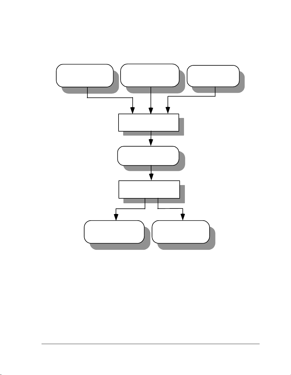
Figure 1-1 shows a graphical overview of the assembly process. The figure
shows the preprocessor processing the assembly source (.ASM) and initialization data (.DAT) files.
Object files produced by the ADSP-218x and ADSP-219x DSP assemblers
may be used as input to the linker and archiver. You can archive the output of an assembly process into a library file (.DLB), which can then be
linked with other objects into an executable. Use the linker to combine
separately assembled object files and objects from library files to produce
an executable file.
For more information on the linker and archiver, see the VisualDSP++ 3.5
Linker and Utilities Manual for ADSP-218x and ADSP-219x DSPs.
easm218x.exe and easm219x.exe with a specified
A binary object file (.DOJ) and an optional listing (.LST) file are final
results of the successful assembly.
The assembler listing files are text files read for information on the results
of the assembly process. The listing file also provides information about
the imported C data structures. It tells which imports were used within
the program, followed by a more detailed section (see .
on page 1-51). It shows the name, total size and layout with offset for the
members. The information appears at the end of the listing. You must
specify the -l listname.lst option (on page 1-92) to get the
information.
1-4 VisualDSP++ 3.5 Assembler and Preprocessor Manual
VisualDSP++ 3.5 assembler can process your source programs
developed previous VDSP releases including Release 6.1. The
assembly of these programs requires an additional processing steps
described in Chapter 3, “Assembler Enhancements and Legacy
Support” .
for ADSP-218x and ADSP-219x DSPs
IMPORT directive
Page 25
Assembler
Data initialization file
(.DAT)
Object file
(.DOJ)
Assembly source file
(.ASM, .DSP)
Preprocessor
Intermediate
preprocessed file (.IS)
Assembler
Listing file
Header file
(.H)
(.LST)
Figure 1-1. Assembler Input and Output Files
The assembly source file may contain preprocessor commands, such as
#include
, that cause the preprocessor to include header files (.H) into the
source program. The preprocessor’s only output, an intermediate source
.IS), is the assembler’s primary input.
file (
VisualDSP++ 3.5 Assembler and Preprocessor Manual 1-5
for ADSP-218x and ADSP-219x DSPs
Page 26

Assembler Guide
Program Content
Assembly source file statements include assembly instructions, assembler
directives, and preprocessor commands.
Assembly Instructions
Instructions adhere to the DSP’s instruction set syntax documented in the
DSP’s Instruction Set manual. Terminate each instruction with a semicolon (
;). Figure 1-2 on page 1-9 shows an example assembly source file.
To mark the location of an instruction, place an address label at the beginning of an instruction line or on the preceding line. End the label with a
colon (:) before beginning the instruction. Your program then refer to this
memory location using the label instead of an absolute address. The
assembler places no restriction on the number of characters in a label.
Labels are case sensitive. The assembler treats “outer” and “Outer” as
unique labels. For example,
outer: AR = AR-1;
Outer: I1 = AR;
jump outer; //jumps back 2 instructions
Assembler Directives
Directives begin with a period (.) and end with a semicolon (;). The
assembler does not differentiate between directives in lowercase or
uppercase.
For example,
.SECTION/data data1;
.VAR sqrt_coeff[2] = 0x5D1D, 0xA9ED;
For a complete description of the easm218x.exe and easm219x.exe assembler’s directive set, see “Assembler Directives” on page 1-40.
1-6 VisualDSP++ 3.5 Assembler and Preprocessor Manual
This manual prints directives in uppercase to distinguish them
from other assembly statements.
for ADSP-218x and ADSP-219x DSPs
Page 27

Assembler
Preprocessor Commands
Preprocessor commands begin with a pound sign (
#) and end with a car-
riage return. The pound sign must be the first non-white space character
on the line containing the command. If the command is longer than one
line, use a backslash (\) and a carriage return to continue the command
onto the next line.
Do not put any characters between the backslash and the carriage return.
Unlike assembler directives, preprocessor commands are case sensitive and
must be lowercase. For example,
#include "string.h"
#define MAXIMUM 100
For more information, see “Writing Preprocessor Commands” on
page 2-3. For a list of the preprocessor commands, see “Preprocessor
Command Reference” on page 2-11.
Program Structure
An assembly source file defines code (instructions) and data, and organizes
the instructions and data to allow use of the Linker Description File
(LDF) to describe how code and data are mapped into the memory on
your target DSP. The way you structure your code and data into memory
should follow the memory architecture of the target DSP.
Use the
source files. The
.SECTION directive to organize the code and data in assembly
.SECTION directive defines a grouping of instructions and
data that will occupy contiguous memory addresses in the DSP. The name
given in a section directive corresponds to an input section name in the
Linker Description File.
Suggested input section names that you could use in your assembly source
appear in Table 1-1 on page 1-8. Using these predefined names in your
sources makes it easier to take advantage of the default .
LDF file included
in your DSP system.
VisualDSP++ 3.5 Assembler and Preprocessor Manual 1-7
for ADSP-218x and ADSP-219x DSPs
Page 28
Assembler Guide
For more information on the .
LDF files, see the VisualDSP++ 3.5 Linker
and Utilities Manual for 16-Bit Processors.
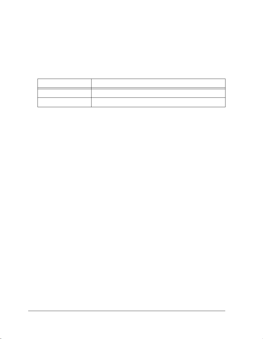
Table 1-1. Suggested Input Section Names
.SECTION Name Description
data1 A section that holds data.
program A section that holds code.
You can use sections in a program to group elements to meet hardware
constraints.
To group the code that reside in off-chip memory, declare a section for
that code and place that section in the selected memory with the linker.
Figure 1-2 on page 1-9 shows how a program divides into sections that
match the memory segmentation of a DSP system.
The example assembly program defines four sections; each section begins
with a .SECTION directive and ends with the occurrence of the next
.SECTION directive or end-of-file. The source program contains two data
and two program sections:
• Data Sections—data1 and constdata. Variables and buffers are
declared and can be initialized.
• Program Sections—
seg_rth and program. Data, instructions, and
statements for conditional assembly are coded.
Looking at Figure 1-2, notice that an assembly source may contain pre-
processor commands, such as #include to include other files in your
source code, #ifdef for conditional assembly, or #define to define
macros.
Assembler directives, such as .VAR, appear within sections to declare and
initialize variables.
1-8 VisualDSP++ 3.5 Assembler and Preprocessor Manual
for ADSP-218x and ADSP-219x DSPs
Page 29

Assembler
Data Section
Data Section
Data Section
Code S ecti on
Assembler
Directive
Co de S ecti on
Assembler
Label and
Instructions
Co de S ecti on
Assembler
Label
Preprocessor
Commands for
Conditional
Assembly
Assembly
Instructions
.SECTION/DATAint_dm1;
.VAR buffer1[0x100] = "text2.txt";
.SECTION/DATA dummy;
.VAR buffer2[0x100];
.SECTION/DATA int_dm3;
.VAR buffer3;
.SECTION/PM seg_1;
.VAR/INIT24 pm_buffer1 = 0x123456;
.SECTION/CODE seg_rth;
JUMP start; RTI;RTI;RTI; // begin execution
RTI;RTI;RTI;RTI;
RTI;RTI;RTI;RTI;
RTI;RTI;RTI;RTI;
RTI;RTI;RTI;RTI;
RTI;RTI;RTI;RTI;
RTI;RTI;RTI;RTI;
RTI;RTI;RTI;RTI;
RTI;RTI;RTI;RTI;
RTI;RTI;RTI;RTI;
RTI;RTI;RTI;RTI;
RTI;RTI;RTI;RTI;
.SECTION/CODE kernel;
start:
#ifndef AR_SET_TO_2
AR = 0x0001;
#endif
#ifdef AR_SET_TO_2
AR = 0x0002;
#endif
I1 = buffer1;
L1=0;
M2=1;
CNTR = 0x100;
DO this_loop UNTIL CE;
this_loop: DM(I1,M2) = AR;
Figure 1-2. Assembly Source File Structure
Listing 1-1 shows a sample user-defined Linker Description File. Looking
at the LDF’s SECTIONS{} command, notice that the INPUT_SECTION commands map to sections
LDF’s
SECTIONS{} command defines the .SECTION placements in the sys-
sec_code, data1, sec_itab, , and seg_rth. The
tem’s physical memory as defined by the linker’s Memory{} command.
VisualDSP++ 3.5 Assembler and Preprocessor Manual 1-9
for ADSP-218x and ADSP-219x DSPs
Page 30

Assembler Guide
Listing 1-1. Example Linker Description File
ARCHITECTURE(ADSP-219x)
SEARCH_DIR($ADI_DSP\ADSP-219x\lib)
LIBS libc.dlb, libdsp.dlb
$LIBRARIES = LIBS, librt.dlb
$OBJECTS = $COMMAND_LINE_OBJECTS;
MEMORY
{
seg_reset { TYPE(PM RAM) START(0x000000) END(0x000001F) WIDTH(24) }
seg_itab { TYPE(PM RAM) START(0x000020) END(0x0002ff) WIDTH(24) }
seg_code { TYPE(PM RAM) START(0x000300) END(0x007fff) WIDTH(24) }
seg_data1 { TYPE(DM RAM) START(0x08000) END(0x00ffff) WIDTH(16) }
}
PROCESSOR p0 /* The processor in the system */
{
LINK_AGAINST( $COMMAND_LINE_LINK_AGAINST)
OUTPUT($COMMAND_LINE_OUTPUT_FILE)
SECTIONS
{ /* List of sections for processor P0 */
sec_reset
{
IVreset_addr = .;
INPUT_SECTIONS( $OBJECTS(IVreset))
} > seg_reset
sec_itab
{
intvectoffset = 32;
IVpwrdwn_addr = .;
INPUT_SECTIONS( $OBJECTS(IVpwrdwn))
IVsinglestep_addr = IVpwrdwn_addr + intvectoffset;
. = IVsinglestep_addr;
INPUT_SECTIONS( $OBJECTS(IVsinglestep))
IVstackint_addr = IVsinglestep_addr + intvectoffset;
. = IVstackint_addr;
INPUT_SECTIONS( $OBJECTS(IVstackint))
IVint4_addr = IVstackint_addr + intvectoffset;
. = IVint4_addr;
INPUT_SECTIONS( $OBJECTS(IVint4))
IVint5_addr = IVint4_addr + intvectoffset;
. = IVint5_addr;
INPUT_SECTIONS( $OBJECTS(IVint5))
IVint6_addr = IVint5_addr + intvectoffset;
. = IVint6_addr;
INPUT_SECTIONS( $OBJECTS(IVint6))
1-10 VisualDSP++ 3.5 Assembler and Preprocessor Manual
for ADSP-218x and ADSP-219x DSPs
Page 31

Assembler
IVint7_addr = IVint6_addr + intvectoffset;
. = IVint7_addr;
INPUT_SECTIONS( $OBJECTS(IVint7))
IVint8_addr = IVint7_addr + intvectoffset;
. = IVint8_addr;
INPUT_SECTIONS( $OBJECTS(IVint8))
IVint9_addr = IVint8_addr + intvectoffset;
. = IVint9_addr;INPUT_SECTIONS( $OBJECTS(IVint9))
IVint10_addr = IVint9_addr + intvectoffset;
. = IVint10_addr;
INPUT_SECTIONS( $OBJECTS(IVint10))
IVint11_addr = IVint10_addr + intvectoffset;
. = IVint11_addr;
INPUT_SECTIONS( $OBJECTS(IVint11))
IVint12_addr = IVint11_addr + intvectoffset;
. = IVint12_addr;
INPUT_SECTIONS( $OBJECTS(IVint12))
IVint13_addr = IVint12_addr + intvectoffset;
. = IVint13_addr;
INPUT_SECTIONS( $OBJECTS(IVint13))
IVint14_addr = IVint13_addr + intvectoffset;
. = IVint14_addr;
INPUT_SECTIONS( $OBJECTS(IVint14))
IVint15_addr = IVint14_addr + intvectoffset;
. = IVint15_addr;
INPUT_SECTIONS( $OBJECTS(IVint15))
. = .+31;
} > seg_itab
seg_code
{
} > seg_code
sec_data1
{
} > seg_data1
}
}
INPUT_SECTIONS( $OBJECTS(program) )
INPUT_SECTIONS( $OBJECTS(data1) )
VisualDSP++ 3.5 Assembler and Preprocessor Manual 1-11
for ADSP-218x and ADSP-219x DSPs
Page 32

Assembler Guide
Program Interfacing Requirements
You can interface your assembly program with a C or C++ program. The
C/C++ compiler supports two methods for mixing C/C++ and assembly
language:
• Embedding assembly code in C or C++ programs
• Linking together C or C++ and assembly routines
To embed (inline) assembly code in your C or C++ program, use the
asm() construct. To link together programs that contain C/C++ and
assembly routines, use assembly interface macros. These macros facilitate
the assembly of mixed routines. For more information about these methods, see the VisualDSP++ 3.5 C/C++ Compiler and Library Manuals for
the target DSPs.
When writing a C or C++ program that interfaces with assembly, observe
the same rules that the compiler follows as it produces code to run on the
DSP. These rules for compiled code define the compiler’s run-time environment. Complying with a run-time environment means following rules
for memory usage, register usage, and variable names.
The definition of the run-time environment for the ADSP-218x and
ADSP-219x DSP’s C/C++ compiler is provided in the VisualDSP++ 3.5
C/C++ Compiler and Library Manuals for the target DSPs, which also
includes a series of examples to demonstrate how to mix C/C++ and
assembly code.
1-12 VisualDSP++ 3.5 Assembler and Preprocessor Manual
for ADSP-218x and ADSP-219x DSPs
Page 33

Assembler
Using Assembler Support for C Structs
The assembler supports C typedef/struct declarations within assembly
source. These are the assembler data directives and built-ins that provide
high-level programming features with C structs in the assembler:
• Data Directives:
.
IMPORT (see on page 1-51)
.EXTERN STRUCT (see on page 1-47)
.STRUCT (see on page 1-69)
• C Struct in Assembly Built-ins:
offsetof(struct/typedef,field) (see on page 1-36)
sizeof(struct/typedef) (see on page 1-37)
• Struct References:
struct->field (nesting supported) (see on page 1-38)
For more information on C struct support, refer to the “-flags-compiler”
command-line switch on page 1-88 and to “Reading a Listing File” on
page 1-18.
C structs in assembly features accept the full set of legal C symbol names,
including those that are otherwise reserved in ADSP-218x and
ADSP-219x assemblers. For example, l1, l2 and l3 are reserved keywords
in the DSP assembler, but it is legal to reference them in the context of the
C struct in assembly features. For example:
.IMPORT "Samples.h";
// typedef struct Samples {
// int I1;
// int I2;
// int I3;
// }Samples;
.SECTION/DATA data1;
VisualDSP++ 3.5 Assembler and Preprocessor Manual 1-13
for ADSP-218x and ADSP-219x DSPs
Page 34

Assembler Guide
.STRUCT Samples Sample1 ={
I1 =0x1000,
I2 =0x2000,
I3 =0x3000
};
.SECTION/CODE program;
doubleMe:
// The code may look confusing, but I2 can be used both
// as a register and a struct member name
I2 = Sample1;
AR = DM(I2+OFFSETOF(Sample1,I2));
AR = AR+AR;
DM(I2+OFFSETOF(Sample1,I2)) = AR;
the same spelling as assembler keywords. This may not always be
possible if your application needs to use an existing set of C header
files.
Preprocessing a Program
The assembler includes a preprocessor that allows the use of C-style preprocessor commands in your assembly source files. The preprocessor
automatically runs before the assembler unless you use the assembler’s
-sp (skip preprocessor) switch. Table 2-3 on page 2-12 lists preprocessor
commands and provides a brief description of each command.
Preprocessor commands are useful for modifying assembly code. For
example, you can use the #include command to fill memory, load config-
For better code readability, avoid .STRUCT member names that have
uration registers, and set up DSP parameters. You can use the
command to define constants and aliases for frequently used instruction
sequences. The preprocessor replaces each occurrence of the macro reference with the corresponding value or series of instructions.
#define
1-14 VisualDSP++ 3.5 Assembler and Preprocessor Manual
for ADSP-218x and ADSP-219x DSPs
Page 35

Assembler
For example, the macro
MAXIMUM in the example on page 1-7 is replaced
with the number 100 during preprocessing.
For more information on the preprocessor command set, see “Preproces-
sor Command Reference” on page 2-11. For more information on
preprocessor usage, see “-flags-pp -opt1 [,-opt2...]” on page 1-90.
Using Assembler Feature Macros
The assembler includes the command to invoke preprocessor macros to
define the context, such as the source language, the architecture, and the
specific processor. These “feature macros” allow the programmer to use
preprocessor conditional commands to configure the source for assembly
based on the context.
The set of feature macros include:
-D_LANGUAGE_ASM =1
-D__ADSP21XX__ =1
-D__ADSP218X__ =1
Always present
Always present
Always defined by easm218x
-D__ADSP219X__ =1
-D__ADSP2181__ =1
-D__ADSP2191__ =1
Always defined by easm219x
Present when running easm218x -proc
ADSP-2181
(for ADSP-218x DSPs)
Present when running easm219x -proc
ADSP-2191
(for ADSP-219x DSPs)
The -proc <processor> switch allows you to specify the processor
and the corresponding macro. For example, using
ADSP-2189 provides you with the -D__ADSP2189__ =1 macro, while
easm219x -proc ADSP-2195 provides you with the
using
-D__ADSP2195__ =1 macro. This is true for all ADSP-218x and
easm218x -proc
ADSP-219x processors.
VisualDSP++ 3.5 Assembler and Preprocessor Manual 1-15
for ADSP-218x and ADSP-219x DSPs
Page 36

Assembler Guide
These are two macro examples.
Example 1:
#ifndef __ADSP218X__
#warning Code optimized for ADSP-218x DSPs
#endif
Example 2:
#if defined(__ADSP2191__)\
|| defined(__ADSP2195__)\
|| defined(__ADSP2196__)
#define NUM_OF_DSP_CORES 1
#elif defined(__ADSP2192_12__)\
#define NUM_OF_DSP_CORES 2
#else
#error Unsupported ADSP processor
#endif
For the .IMPORT headers, the assembler calls the compiler driver with the
appropriate processor option and the compiler sets the machine constants
accordingly (and defines -D_LANGUAGE_C = 1 ). This macro is present when
used for C compiler calls to specify headers. It replaces -D_LANGUAGE_ASM.
For example,
easm218x -2189 assembly --> cc218x -2189
easm219x -2191 assembly --> cc219x -2191
Use the -verbose option to verify what macro is default-defined.
Refer to Chapter 1 in the VisualDSP++ 3.5 C/C++ Compiler and
Library Manuals for target DSPs for more information.
1-16 VisualDSP++ 3.5 Assembler and Preprocessor Manual
for ADSP-218x and ADSP-219x DSPs
Page 37

Assembler
Make Dependencies
The assembler can generate “make dependencies” for a file to allow
VisualDSP++ and other makefile-based build environments to determine
when to rebuild an object file due to changes in the input files. The assembler source file and any files mentioned in the
.IMPORT directives, or buffer initializations (in .VAR and .STRUCT directives)
constitute the “make dependencies” for an object file.
When VisualDSP++ requests make dependencies for the assembly, the
assembler produces the dependencies from buffer initializations and
invokes
• The preprocessor to determine the make dependency from
#include commands, and
• The compiler to determine the make dependencies from the
.IMPORT headers.
#include commands,
The following example shows make dependencies for VCSE_IBase.h which
includes vcse.h. Note that the same header VCSE_IBase.h when called
from the assembler (with assembler #defines) also includes VCSE_asm.h,
but this was not the case when called for compiling .IMPORT.
easm219x -M -l main.lst main.asm
// dependency from the assembler
main.doj": "main.asm"
// dependencies from the assembler preprocessor PP for the
// #include headers
"main.doj": "ACME_Impulse_factory.h"
"main.doj": "ACME_Impulse_types.h"
"main.doj": "VCSE_IBase.h"
"main.doj": "VCSE_asm.h"
"main.doj": "vcse.h"
VisualDSP++ 3.5 Assembler and Preprocessor Manual 1-17
for ADSP-218x and ADSP-219x DSPs
Page 38

Assembler Guide
// dependencies from the compiler for the .IMPORT headers
main.doj: .\ACME_IFir.h
main.doj: .\ADI_IAlg.h
main.doj: .\VCSE_IBase.h
main.doj: .\vcse.h
Reading a Listing File
A listing file (.LST) is an optional output text file that lists the results of
the assembly process. Listing files provide the following information:
• Address — The first column contains the offset from the .SEC-
TION’s base address.
• Opcode — The second column contains the hexadecimal opcode
that the assembler generates for the line of assembly source.
• Line — The third column contains the line number in the assembly source file.
• Assembly Source — The fourth column contains the assembly
source line from the file.
The assembler listing file provides information about the imported C data
structures. It tells which imports were used within the program, followed
by a more detailed section. It shows the name, total size and layout with
offset for the members. The information appears at the end of the listing.
You must specify the -l listname.lst option (as shown on page 1-92) to
get a listing file.
1-18 VisualDSP++ 3.5 Assembler and Preprocessor Manual
for ADSP-218x and ADSP-219x DSPs
Page 39

Assembler
Assembler Syntax Reference
When you develop a source program in assembly language, include preprocessor commands and assembler directives to control the program’s
processing and assembly. You must follow the assembler rules and conventions of syntax to define symbols (identifiers), expressions, and use
different numeric and comment formats.
Software developers who write assembly programs should be familiar with:
• “Assembler Keywords and Symbols” on page 1-19
• “Assembler Expressions” on page 1-27
• “Assembler Operators” on page 1-28
• “Numeric Formats” on page 1-30
• “Comment Conventions” on page 1-33
• “Conditional Assembly Directives” on page 1-34
• “C Struct Support in Assembly Built-in Functions” on page 1-36
• “-> Struct References” on page 1-38
• “Assembler Directives” on page 1-40
Assembler Keywords and Symbols
The assembler supports predefined keywords that include register and bitfield names, assembly instructions, and assembler directives. Table 1-2
lists the assembler keywords for ADSP-218x DSPs. Table 1-3 lists the
assembler keywords for ADSP-219x DSPs. Although the keywords in the
listings appear in uppercase, the keywords are case insensitive in the
assembler’s syntax. For example, the assembler does not differentiate
between “DATA” and “data”.
VisualDSP++ 3.5 Assembler and Preprocessor Manual 1-19
for ADSP-218x and ADSP-219x DSPs
Page 40

Assembler Syntax Reference
Table 1-2. ADSP-218x DSP Assembler Keywords
.ALIGN .ASM_ASSERT .BYTE .DMSEG .ELIF
.ELSE .END_REPEAT .ENDIF .ENDINCLUDE .ENDMACRO
.ENDMOD .ENTRY .EXPORT .EXTERN .EXTERNAL
.FILE .GLOBAL .IF .IMPORT .INCLUDE
.INDENT .INIT .INIT24 .LEFTMARGIN .LIST
.LIST_DATA .LIST_DATFILE .LIST_DEFTAB .LIST_LOCTAB
.LOCAL .MACRO .MODULE .NEWPAGE .NOLIST
.NOLIST_DATA
.PAGELENGTH .PAGEWIDTH .PMSEG .PORT .PRECISION
.PREVIOUS .REPEAT .ROUND_MINUS .ROUND_NEAREST .ROUND_PLUS
.ROUND_ZERO .SECTION .SETDATA .SIZE .STRUCT
.TYPE .VAR
.WEAK
__DATE__ __FILE__ __LINE__ __STDC__ __TIME__
ABS AC ADDRESS AF AND
AR AR_SAT AS ASHIFT ASTAT
AV AV_LATCH AX0 AX1 AYO
AY1
BIT_REV BOOT BR BY
.NOLIST_DATFILE
.NOLIST_WRAPDATA
.VCSE_METHODCALL
_END
.ORG .PAGE
.VCSE_METHODCALL
_START
.LIST_WRAPDATA
.VCSE_METHODCALL
_RETURNS
C CALL CE CIRC CLRBIT
CLRBIT CLRINT CNTR CODE CONST
DATA DIS DIVQ DIVS DM
DMOVLAY D0
1-20 VisualDSP++ 3.5 Assembler and Preprocessor Manual
for ADSP-218x and ADSP-219x DSPs
Page 41

Assembler
Table 1-2. ADSP-218x DSP Assembler Keywords (Cont’d)
E_MODE EMUIDLE ENDINCLUDE ENDMACRO E0
EXP EXPADJ
FI FL0 FL1 FL2 FLAG_IN
FLAG_OUT FLUSH FO FOREVER
G_MODE GE GM GT
HI HIX
I0 I1 I2 I3 I4
I5 I6 I7 ICNTL IDLE
IF IFC IMASK INCLUDE INIT24
INT INTS IO ISTAT
JUMP
L0 L1 L2 L3 L4
L5 L6 L7 LE LENGTH
LINE LO LOOP LSHIFT LT
M0 M1 M2 M3 M4
M5 M6 M7 M_MODE MACRO
MF MODIFY MR MR0 MR1
MR2 MSTAT MV MX0 MX1
MY0 MY1
NE NEG NONE NOP NORM
NOT
OF OFFSET OL OR OWRCNTR
PAGE PAGEID PASS PC PM
PMCODE PMDATA PMOVLAY POP POS
PUSH PX
VisualDSP++ 3.5 Assembler and Preprocessor Manual 1-21
for ADSP-218x and ADSP-219x DSPs
Page 42

Assembler Syntax Reference
Table 1-2. ADSP-218x DSP Assembler Keywords (Cont’d)
RAM RESET RND ROM RTI
RTS RX0 RX1
SAT SB SE SEC_REG SEG
SET SETBIT SETINT SHIFT SHT_DEBUGINFO
SHT_DM SHT_DYNAMIC SHT_DYNSYM SHT_HASH SHT_LDF
SHT_NOBITS SHT_NOTE SHT_NULL SHT_PMCODE SHT_PMDATA
SHT_PROCESSORTYPE
SHT_SHLIB SHT_STRTAB SHT_SYMTAB SI SIMIDLE
SIZEOF SR SR0 SR1 SS
SSTAT STATIC STRUCT STS STT_FUNC
STT_OBJECT SU
TGLBIT TI TIMER TOGGLE TOPLOOPSTACKH
TOPLOOPSTACKL TOPPCSTACK TRAP TRUE TSTBIT
TX0 TX1
UNTIL US UU
XOR
SHT_PROGBITS SHT_REL SHT_RELA
SHT_SEGMENINFO
Table 1-3. ADSP-219x DSP Assembler Keywords
.ALIGN .ASM_ASSERT .BYTE .DATA .DMBSS
.DMSEG .DW .ELIF .ELSE .END_REPEAT
.ENDIF .ENDINCLUDE .ENDMACRO .ENDMOD .ENTRY
.EXPORT .EXTERN .EXTERNAL .FILE .GENLABEL
.GLOBAL .IF
.IMPORT .INCLUDE .INDENT
.INIT .INIT24 .LEFTMARGIN .LIST .LIST_DATA
.LIST_DATFILE .LIST_DEFTAB .LIST_LOCTAB .LIST_WRAPDATA .LOCAL
1-22 VisualDSP++ 3.5 Assembler and Preprocessor Manual
for ADSP-218x and ADSP-219x DSPs
Page 43

Assembler
Table 1-3. ADSP-219x DSP Assembler Keywords (Cont’d)
.MACRO .MODULE .NEWPAGE .NOLIST .NOLIST_DATA
.NOLIST_DATFILE
.PAGEWIDTH .PMBSS .PMSEG .PORT .PRECISION
.PREVIOUS .REPEAT .ROUND_MINUS .ROUND_NEAREST .ROUND_PLUS
.ROUND_ZERO .SECTION .SETDATA .SIZE .STRUCT
.TYPE .VAR .WEAK
__DATE__ __FILE__ __LINE__ __STDC__ __TIME__
ABS AC ADDRESS AF AND
AR AR_SAT AS ASHIFT ASTAT
AV AV_LATCH AX0 AX1 AYO
AY1
B0 B1 B2 B3 B4
B5 B6 B7 BIT_REV BOOT
BR BY
C CACHE CACTL CALL CCODE
CE CIRC CLRBIT CLRINT CNTR
.NOLIST_WRAPDATA
.ORG .PAGE .PAGELENGTH
CODE
DATA DB DIS DIVQ DIVS
DM DMPG1 DMPG2 D0 DW
DX
E_MODE EMUIDLE ENA ENDINCLUDE ENDMACRO
EQ ETRAP EXP EXPADJ
FL0 FL1 FL2 FLAG_OUT FLUSH
VisualDSP++ 3.5 Assembler and Preprocessor Manual 1-23
for ADSP-218x and ADSP-219x DSPs
Page 44

Assembler Syntax Reference
Table 1-3. ADSP-219x DSP Assembler Keywords (Cont’d)
FOREVER
GE GT
HI HIX
I0 I1 I2 I3 I4
I5 I6 I7 INCTL IDLE
IF IJPG IMASK INCLUDE INIT24
INT IO IOPG IRPTL
JUMP KTRAP
L0 L1 L2 L3 L4
L5 L6 L7 LCALL LE
LENGTH LINE LJUMP LO LOOP
LPSTACKA LPSTACKP LSHIFT LT
M0 M1 M2 M3 M4
M5 M6 M7 M_MODE MACRO
MF MM MODIFY MR MR0
MR1 MR2 MSTAT MV MXO
MX1 MYO MY1
NE NEG NONE NOP NORM
NOT
OF OFFSETOF OL OR
PAGE PAGEID PASS PC PM
PMCODE PMDATA POP POS PUSH
PX
RAM REG RESET RND ROM
RTI RTS
1-24 VisualDSP++ 3.5 Assembler and Preprocessor Manual
for ADSP-218x and ADSP-219x DSPs
Page 45

Assembler
Table 1-3. ADSP-219x DSP Assembler Keywords (Cont’d)
SAT SB SD SE SEC_DAG
SEC_REG SEG SET SETBIT SETINT
SHIFT SHT_DEBUGINFO SHT_DM SHT_DYNAMIC SHT_DYNSYM
SH_HASH SHT_LDF SHT_NOBITS SHT_NOTE SHT_NULL
SHT_PMCODE SHT_PMDATA
SHT_RELA
SI SIMIDLE SIZEOF SR SR0
SR1 SR2 SS SSTAT STACKA
STACKP STATIC STEP STRUCT STS
STT_FUNC STT_OBJECT SU SV SWCOND
SYSCTL
TGLBIT TI TIMER TOGGLE TRAP
TRUE TSTBIT TX0 TX1
UNTIL US UU
XOR
WAIT WARNING WRITE WEAK
XOR
SHT_SEGMENTINFO
SHT_PROCESSORTYPE
SHT_SHLIB SHT_STRTAB SHT_SYMTAB
SHT_PROGBITS SHT_REL
Extend these sets of keywords with symbols that declare sections, variables, constants, and address labels. When defining symbols in assembly
source code, follow these conventions:
• Define symbols that are unique within the file in which they are
declared. If you use a symbol in more than one file, use the .GLOBAL
assembly directive to export the symbol from the file in which it is
defined. Then use the
.EXTERN assembly directive to import the
symbol into other files.
VisualDSP++ 3.5 Assembler and Preprocessor Manual 1-25
for ADSP-218x and ADSP-219x DSPs
Page 46

Assembler Syntax Reference
• Begin symbols with alphabetic characters.
Symbols can use alphabetic characters (
A—Z and a—z), digits (0—9),
and special characters $ and _ (dollar sign and underscore) as well
as . (dot).
Symbols are case sensitive; so input_addr and INPUT_ADDR define
unique variables.
The dot, point, or period, '.' as the first character of a symbol triggers special behavior in the VisualDSP++ environment. Such
symbols will not appear in the symbol table accessible in the debugger. A symbol name in which the first two characters are points will
not appear even in the symbol table of the object.
The compiler and runtimes prepend '_' to avoid using symbols in
the user name space that begin with an alphabetic character.
• Do not use a reserved keyword to define a symbol.
• Match source and LDF sections’ symbols.
Ensure that .SECTION name symbols do not conflict with the
linker’s keywords in the LDF. The linker uses sections’ name symbols to place code and data in DSP memory. For more details, see
the VisualDSP++ 3.5 Linker and Utilities Manual for 16-Bit Proces-
sors.
Ensure that .
SECTION name symbols do not begin with the ‘.’ (dot).
• Terminate address label symbols with a colon (:).
• The reserved word list for ADSP-218x and ADSP-219x DSPs
includes some keywords with commonly used spellings; therefore,
ensure correct syntax spelling.
1-26 VisualDSP++ 3.5 Assembler and Preprocessor Manual
for ADSP-218x and ADSP-219x DSPs
Page 47

Assembler
Address label symbols may appear at the beginning of an instruction line
or stand alone on the preceding line. The following disassociated lines of
code demonstrate symbol usage.
.VAR xoperand; // xoperand is a 16-bit variable
.VAR/INIT24 input_array[10]; // input_array is a 24-bit wide
// data buffer in PM
sub_routine_1: // sub_routine_1 is a label
.SECTION/PM kernel; // kernel is a section in PM
Assembler Expressions
The assembler can evaluate simple expressions in source code. The assembler supports two types of expressions: constant and symbolic.
Constant expressions
A constant expression is acceptable where a numeric value is expected in
an assembly instruction or in a preprocessor command. Constant expressions contain an arithmetic or logical operation on two or more numeric
constants. For example,
2.9e-5 + 1.29
(128-48)/3
0x55&0x0f
7.6r
– .8r
For information about fraction type support, refer to “Fractional Type
Support” on page 1-31.
Symbolic expressions
Symbolic expressions contain symbols, whose values may not be known
until link time:
data/8
(data_buffer1 + data_buffer2) & 0xF
strtup + 2
data_buffer1 + LENGTH(data_buffer2)*2
VisualDSP++ 3.5 Assembler and Preprocessor Manual 1-27
for ADSP-218x and ADSP-219x DSPs
Page 48

Assembler Syntax Reference
Symbols in this type of expression are data variables, data buffers, and program labels. In the first three examples above, the symbol name represents
the address of the symbol. The fourth combines that meaning of a symbol
with a use of the length operator (see Table 1-5).
Assembler Operators
Table 1-4 lists the assembler’s numeric and bitwise operators used in con-
stant expressions and address expressions. These operators are listed in the
order they are processed while the assembler evaluates your expressions.
Relational operators are only supported in relational expressions in conditional assembly, as described in “Conditional Assembly Directives” on
page 1-34.
Table 1-4. Operator Precedence
Operator Usage Description Designation
(expression) expression in parentheses evaluates first
~
-
*
/
%
+
–
<<
>>
& Bitwise AND (preprocessor only)
| Bitwise inclusive OR
^ Bitwise exclusive OR (preprocessor only)
Ones complement
Unary minus
Multiply
Divide
Modulus
Addition
Subtraction.
Shift left
Shift right
Tilde
Minus
Asterisk
Slash
Percentage
Plus
Minus
1-28 VisualDSP++ 3.5 Assembler and Preprocessor Manual
for ADSP-218x and ADSP-219x DSPs
Page 49

Assembler
The assembler also supports special “symbol” and “length of” operators.
Table 1-5 lists and describes these operators used in constant and address
expressions.
Table 1-5. Special Assembler Operators
Operator Usage Description
ADDRESS(symbol) Least significant 16 address bits of symbol
symbol
LENGTH(symbol)
PAGE(symbol) Most significant 8 address bits associated with symbol.
Address pointer to symbol
Length of symbol in words
The “length of” operator can be used with external symbols—apply it to
symbols that are defined in other sections as
.GLOBAL symbols.
The following example demonstrates how the assembler operators are used
to load the length and address information into registers (when setting up
circular buffers in ADSP-219x processors).
.SECTION/DATA data1; // data section
.VAR real_data [n]; // n=number of input sample
.SECTION/CODE program; // code section
I5=real_data; // buffer’s base address
L5=length(real_data); // buffer’s length
AR=I5; // load address to data register
REG(B5)=AR;
M=1; // post-modify I5 by 1
CNTR=DO loop1 UNTIL CE;
AX0=DM(I5,M4); // get next sample
…
loop1: …
VisualDSP++ 3.5 Assembler and Preprocessor Manual 1-29
for ADSP-218x and ADSP-219x DSPs
Page 50

Assembler Syntax Reference
This code fragment initializes
I5 and L5 to the base address and length,
respectively, of the circular buffer real_data. The buffer length value
contained in L5 determines when addressing wraps around the top of the
buffer. For further information on circular buffers, refer to the target processor’s Hardware Reference Manual.
The following example illustrates how the PAGE() operator can be used to
handle overlays on ADSP-218x processors.
.SECTION/PM IVreset;
jump start;
.SECTION/PM program;
start:
pmovlay = PAGE(func4);
call func4;
ar = ay0;
dmovlay = PAGE(dmovl3var);
ay0 = dm(dmovl3var);
ar = ar + ay0;
idle;
.SECTION/PM pmovl4;
func4:
ay0 = 0x0004;
rts;
.SECTION/DM dmovl3;
.VAR dmovl3var = 0x0104;
Numeric Formats
The assembler supports binary, decimal, hexadecimal, and fractional
numeric formats (bases) within expressions and assembly instructions.
Table 1-6 describes the conventions of notation the assembler uses to dis-
tinguish between numeric formats.
1-30 VisualDSP++ 3.5 Assembler and Preprocessor Manual
for ADSP-218x and ADSP-219x DSPs
Page 51

Table 1-6. Numeric Formats
Convention Description
0xnumber “0x” prefix indicates a hexadecimal number
Assembler
B#number
b#number
number No prefix indicates a decimal number
numberr “r” suffix indicates a fractional number
“
B#” or “b#” prefix indicates a binary number
Fractional Type Support
Fractional (fract) constants are specially marked floating-point constants
to be represented in fixed-point. A fract constant uses the floating-point
representation with a trailing “
r”, where r stands for fract.
The legal range is [– 1…1). Fracts are represented as signed values, which
means the values must be greater than or equal – 1 and less than 1.
For example,
.VAR myFracts[] = 0.5r, -0.5e-4r, -0.25e-3r, 0.875r;
/* Constants are examples of legal fracts */
.VAR OutOfRangeFract = 1.5r;
/* [Error ea1036] "fractErr.asm":3 Fract constant '1.5r'
is out of range. Fract constants must be greater than
or equal to -1 and less than 1.
Constants .5r and .2r are examples of legal fracts in
assembly source */
1.15 Fracts
The ADSP-218x and ADSP-219x DSs support fracts that use 1.15 format,
meaning a sign bit and “15 bits of fraction”. This is
example, 1.15 maps the constant
0.5r to 2**14.
–1 to +1–2**15. For
VisualDSP++ 3.5 Assembler and Preprocessor Manual 1-31
for ADSP-218x and ADSP-219x DSPs
Page 52

Assembler Syntax Reference
The conversion formula used by a ADSP-218x or ADSP-219x DSP to
convert from the floating-point format to fixed-point format uses a scale
factor of 15:
fractValue = (short) (doubleValue * (1 << 15))
For example:
.VAR myFract = 0.5r;
// Fract output for 0.5r is 0x4000
// sign bit + 15 bits
// 0100 0000 0000 0000
// 4 0 0 0 = 0x4000 = .5r
VAR myFract = -1.0r;
// Fract output for -1.0r is 0x8000
// sign bit + 15 bits
// 1000 0000 0000 0000
// 8 0 0 0 = 0x8000 = -1.0r
1.0r Special Case
1.0r is out of the range fract. Specify 0x7FFF for the closest approximation
of 1.0r within the 1.15 representation.
Fractional Arithmetic
The assembler provides supports for arithmetic expressions using operations on fractional constants, consistent with the support for other
numeric types in constant expressions, as described in “Assembler Expres-
sions” on page 1-27.
The internal (intermediate) representation for expression evaluation is a
double floating-point value. Fract range checking is deferred until the
expression is evaluated. For example,
#define fromSomewhereElse 0.875r
.SECTION/dm data1;
1-32 VisualDSP++ 3.5 Assembler and Preprocessor Manual
for ADSP-218x and ADSP-219x DSPs
Page 53

Assembler
.VAR localOne = fromSomewhereElse + 0.005r;
// Result .88r is within the legal range
.VAR xyz = 1.5r -0.9r;
// Result .6r is within the legal range
.VAR abc = 1.5r; // Error: 1.5r out of range
Mixed Type Arithmetic
The assembler does not support arithmetic between fracts and integers.
For example,
.SECTION/code program;
.VAR myFract = 1 - 0.5r;
[Error ea1998] "fract.asm":2 Assembler Error: Illegal
mixing of types in expression.
Comment Conventions
The assembler supports C and C++ style formats for inserting comments
in assembly sources. The easm218x and easm219x assemblers do not support nested comments. Table 1-7 lists and describes assembler comment
conventions.
Table 1-7. Comment Conventions
Convention Description
/* comment */ A “/* */” string encloses a multiple-line comment.
comment A pair of slashes “//” begin a single-line comment.
//
VisualDSP++ 3.5 Assembler and Preprocessor Manual 1-33
for ADSP-218x and ADSP-219x DSPs
Page 54

Assembler Syntax Reference
Conditional Assembly Directives
Conditional assembly directives are used for evaluation of assembly-time
constants using relational expressions. The expressions may include relational and logical operations. In addition to integer arithmetic, the
operands may be the C struct in assembly built-in functions
OFFSETOF() that return integers.
The conditional assembly directives are:
• .IF constant-relational-expression;
• .ELIF constant-relational-expression;
• .ELSE;
• .ENDIF;
All conditional assembly blocks begin with an .IF directive and end with a
.ENDIF directive. Table 1-8 shows examples of conditional directives.
SIZEOF()and
Table 1-8. Relational Operators for Conditional Assembly
Relational Operators Conditional Directive Examples
not ! .if !0;
greater than > .if ( sizeof(myStruct) > 16 );
greater than equal >= .if ( sizeof(myStruct) >= 16 );
less than < .if ( sizeof(myStruct) < 16 );
less than equal <=
equality == .if ( 8 == sizeof(myStruct) );
not equal != .if ( 8 != sizeof(myStruct) );
logical or || .if (2 !=4 ) || (5 == 5);
logical and && .if (sizeof(char) == 2 && sizeof(int) == 4);
.if ( sizeof(myStruct) <= 16 );
1-34 VisualDSP++ 3.5 Assembler and Preprocessor Manual
for ADSP-218x and ADSP-219x DSPs
Page 55

Assembler
Optionally, any number of
within the .IF and .ENDIF. The conditional directives are each terminated
with a semi-colon ";" just like all existing assembler directives. Conditional directives do not have to appear alone on a line. These directives are
in addition to the C-style preprocessing directives #if, #elif, #else, and
#endif.
The .IF conditional assembly directives must be used to query about C
structs in assembly using the SIZEOF() and/or OFFSETOF() built-ins. These
built-ins are evaluated at assembly time, so they cannot appear in expressions in the #if preprocessor directives.
In addition, the SIZEOF() and OFFSETOF() built-in functions (see “C
Struct Support in Assembly Built-in Functions” on page 1-36) can be used
in relational expressions. Different code sequences can be included based
on the result of the expression.
For example, a SIZEOF(struct/typedef/C base type) is permitted.
The assembler supports nested conditional directives. The outer conditional result propagates to the inner condition, just as it does in C
preprocessing.
The ".IF", ".ELSE", ".ELIF “ and ".ENDIF" directives (in any case)
are reserved keywords.
.ELIF and a final .ELSE directive may appear
Assembler directives are distinct from preprocessor directives:
• The # directives are evaluated during preprocessing by the
processor. Therefore, preprocessor #IF directives cannot use the
assembler built-in functions (see “C Struct Support in Assembly
Built-in Functions”).
• The conditional assembly directives are processed by the assembler
in a later pass. Therefore, you would be able to write a relational or
logical expression whose value will depend on the value of a
#define:. For example,
VisualDSP++ 3.5 Assembler and Preprocessor Manual 1-35
for ADSP-218x and ADSP-219x DSPs
PP pre-
Page 56

Assembler Syntax Reference
.
IF tryit == 2
<some code>
.ELIF tryit >= 3
<some more code>
If you have "#define tryit 2", then the code <some code> will be
assembled, <some more code> will not be.
• There are no parallel assembler directives for C-style directives
#define, #include, #ifdef, #if defined(name), #ifndef, etc.
C Struct Support in Assembly Built-in Functions
The assembler supports built-in functions that enable you to pass information obtained from the imported C struct layouts. The supported
built-in functions are OFFSETOF() and SIZEOF().
OFFSETOF() Built-In
The OFFSETOF() built-in function is used to calculate the offset of a specified member from the beginning of its parent data structure. For
ADSP-218x and ADSP-219x DSPs, OFFSETOF() units are in words.
OFFSETOF( struct/typedef, memberName )
where:
struct/typedef—struct VAR or a typedef can be supplied as the
first argument
memberName—a member name within the struct or typedef (sec-
ond argument)
1-36 VisualDSP++ 3.5 Assembler and Preprocessor Manual
for ADSP-218x and ADSP-219x DSPs
Page 57

Assembler
SIZEOF() Built-In
The
SIZEOF() built-in function returns the amount of storage associated
with an imported C struct or data member. It provides functionality similar to its C counterpart.
SIZEOF(struct/typedef/C base type);
where:
SIZEOF() takes a symbolic reference as its single argument. A sym-
bolic reference is a name followed by zero or more qualifiers to
members. The SIZEOF() built-in function gives the amount of storage associated with:
• An aggregate type (structure)
• A C base type (int, char, etc.)
• A member of a structure (any type)
For example,
.IMPORT "Celebrity.h";
.EXTERN STRUCT Celebrity StNick;
.SECTION/CODE program;
l3 = SIZEOF(Celebrity); // typedef
l3 = SIZEOF(StNick); // struct var of typedef Celebrity
l3 = SIZEOF(char); // C built-in type
l3 = SIZEOF(StNick->Town); // member of a struct var
l3 = SIZEOF(Celebrity->Town); // member of a struct typedef
The SIZEOF() built-in function returns the size in the units appro-
priate for its processor. For ADSP-218x and ADSP-219x DSPs,
units are in words.
VisualDSP++ 3.5 Assembler and Preprocessor Manual 1-37
for ADSP-218x and ADSP-219x DSPs
Page 58

Assembler Syntax Reference
When applied to a structure type or variable,
sizeof() returns the actual
size, which may include padding bytes inserted for alignment. When
applied to a statically dimensioned array, sizeof() returns the size of the
entire array.
-> Struct References
A reference to a struct VAR provides an absolute address. For a fully qualified reference to a member, the address is offset to the correct location
within the struct. The assembler syntax for
For example,
myStruct->Member5
references the address of Member5 located within myStruct. If the struct
layout changes, there is no need to change the reference. The assembler
re-calculates the offset when the source is re-assembled with the updated
header. Nested struct references are supported.
For example,
myStruct->nestedRef->AnotherMember
struct references is “->”.
always referenced with “->” (and not “.”) because “."“is a legal
character in identifiers in assembly and not available as a struct
reference.
References within nested structures are permitted. A nested struct definition can be provided in a single reference in assembly code while a nested
Unlike struct members in C, struct members in the assembler are
struct via a pointer type requires more than one instruction. Make use of
OFFSETOF() built-in function to avoid hard-coded offsets that could
the
become invalid if the struct layout changes in the future.
Following are two nested
struct examples for .IMPORT
"CHeaderFile.h";
1-38 VisualDSP++ 3.5 Assembler and Preprocessor Manual
for ADSP-218x and ADSP-219x DSPs
.
Page 59

Assembler
Example 1: Nested Reference Within the Struct Definition with Appropriate C Declarations
C code
struct Location {
char Town[16];
char State[16];
};
struct myStructTag
int field1;
struct Location NestedOne;
};
Assembly Code
.EXTERN STRUCT myStructTag _myStruct;
AR = _myStruct->NestedOne->State;
Example 2: Nested Reference When Nested via a Pointer with Appropriate C Declarations
When nested via a pointer myStructTagWithPtr, which has pNestedOne,
use pointer register offset instructions.
C Code
// from C header
struct Location {
char Town[16];
char State[16];
};
struct myStructTagWithPtr {
int field1;
struct Location *pNestedOne;
};
VisualDSP++ 3.5 Assembler and Preprocessor Manual 1-39
for ADSP-218x and ADSP-219x DSPs
Page 60

Assembler Syntax Reference
Assembly Code
// in assembly file
.EXTERN STRUCT myStructTagWithPtr _myStructWithPtr;
AR = _myStructWithPtr->pNestedOne;
AR = AR+OFFSETOF(Location,State);
Assembler Directives
Directives in an assembly source file control the assembly process. Unlike
assembly instructions, directives do not produce opcodes during assembly.
Use the following general syntax for assembler directives
.directive [/qualifiers |arguments];
Each assembler directive starts with a period (.) and ends with a semicolon (;). Some directives take qualifiers and arguments. A directive’s
qualifier immediately follows the directive and is separated by a slash (/);
arguments follow qualifiers. Assembler directives can be uppercase or lowercase; uppercase distinguishes directives from other symbols in your
source code.
The ADSP-218x and ADSP-219x DSP assemblers support the directives
shown in Table 1-9. A description of each directive appears in the following sections.
Table 1-9. Assembler Directive Summary
Directive Description
.ALIGN
(see on page 1-44)
.ELSE
(see on page 1-34)
.ENDIF
(see on page 1-34)
Specifies a byte alignment requirement
Conditional assembly directive
Conditional assembly directive
1-40 VisualDSP++ 3.5 Assembler and Preprocessor Manual
for ADSP-218x and ADSP-219x DSPs
Page 61

Table 1-9. Assembler Directive Summary (Cont’d)
Directive Description
Assembler
.EXTERN
(see on page 1-46)
.EXTERN STRUCT
(see on page 1-47)
.FILE
(see on page 1-49)
.GLOBAL
(see on page 1-50)
.IF
(see on page 1-34)
.IMPORT
(see on page 1-50)
.LEFTMARGIN
(see on page 1-53)
.LIST
(see on page 1-54)
.LIST_DATA
(
see on page 1-55)
.LIST_DATFILE
(see on page 1-56)
Allows reference to a global symbol
Allows reference to a global symbol (struct) that was
defined in another file
Overrides filename given on the command line. Used by C
compiler
Changes a symbol’s scope from local to global
Conditional assembly directive
Provides the assembler with the structure layout (C struct)
information
Defines the width of the left margin of a listing
Starts listing of source lines
Starts listing of data opcodes
Starts listing of data initialization files
.LIST_DEFTAB
Sets the default tab width for listings
(see on page 1-57)
.LIST_LOCTAB
Sets the local tab width for listings
(see on page 1-58)
.LIST_WRAPDATA
Starts wrapping opcodes that don’t fit listing column
(see on page 1-59)
.NEWPAGE
Inserts a page break in a listing
(see on page 1-60)
.NOLIST
Stops listing of source lines
(see on page 1-54)
VisualDSP++ 3.5 Assembler and Preprocessor Manual 1-41
for ADSP-218x and ADSP-219x DSPs
Page 62

Assembler Syntax Reference
Table 1-9. Assembler Directive Summary (Cont’d)
Directive Description
.NOLIST_DATA
(see on page 1-55)
.NOLIST_DATFILE
(see on page 1-56)
.NOLIST_WRAPDATA
(see on page 1-59)
.PAGELENGTH
(see on page 1-61)
.PAGEWIDTH
(see on page 1-62)
.PREVIOUS
(see on page 1-63)
.R
EPEAT/.END_REPEAT
(see on page 1-65)
.SECTION
(see on page 1-67)
.STRUCT
(see on page 1-69)
.TYPE
(see on page 1-74)
Stops listing of data opcodes
Stops listing of data initialization files
Stops wrapping opcodes that don't fit listing column
Defines the length of a listing page
Defines the width of a listing page
Reverts to a previously described
Provides an automated way for loop unrolling.
.SECTION
Marks the beginning of a section
Defines and initializes data objects based on C
typedefs from .IMPORT C header files
Changes the default data type of a symbol.
Used by C compiler
.VAR
Defines and initializes 32-bit data objects
(see on page 1-75)
.VCSE_
Used as optimization directives for VCSE components
(see on page 1-80)
.WEAK
Creates a weak definition or reference
(see on page 1-81)
The ADSP-218x and ADSP-219x DSP assemblers also support Release
6.1 directives shown in Table 3-2 on page 3-4. To re-assemble a program
that uses any of these directives with easm218x or easm219x assemblers,
1-42 VisualDSP++ 3.5 Assembler and Preprocessor Manual
for ADSP-218x and ADSP-219x DSPs
Page 63

Assembler
use the
and syntax conventions, see Chapter 3, “Assembler Enhancements and
Legacy Support”.
-legacy switch. For more information about the legacy directives
Current (and future) DSP development tools may not support legacy directives or conventions of syntax. Analog Devices strongly
recommends to revise source programs developed under Release
6.1 for use with VisualDSP++ tools.
VisualDSP++ 3.5 Assembler and Preprocessor Manual 1-43
for ADSP-218x and ADSP-219x DSPs
Page 64

Assembler Syntax Reference
.ALIGN, Specify an Address Alignment
The
.ALIGN directive forces the address alignment of an instruction or
data item. Use it to ensure section alignments in the .LDF file. You may use
.ALIGN to ensure the alignment of the first element of a section, therefore
providing the alignment of the object section (“input section” to the
linker). You may also use the INPUT_SECTION_ALIGN(#number) linker command in the .LDF file to force all the following input sections to the
specified alignment.
Refer to Chapter 2 “Linker” in the VisualDSP++ 3.5 Linker and Utilities
Manual for 16-Bit Processors for more information on section alignment.
Syntax:
.ALIGN expression;
where
expression — evaluates to an integer. It specifies the byte align-
ment requirement; its value must be a power of 2. When aligning a
data item or instruction, the assembler adjusts the address of the
current location counter to the next address that can be evenly
divided by the value of expression. The expression set to 0 or 1
signifies no address alignment requirement.
In the absence of the .ALIGN directive, the default address align-
ment is 1.
Example
.ALIGN 0; /* no alignment requirement */
…
.ALIGN 1; /* no alignment requirement */
…
.SECTION/DM data1;
1-44 VisualDSP++ 3.5 Assembler and Preprocessor Manual
for ADSP-218x and ADSP-219x DSPs
Page 65

.ALIGN 2;
.VAR single;
/* aligns the data item in DM on the word boundary,
at the location with the address value that can be
evenly divided by 2 */
.ALIGN 4;
.VAR samples1[100]=”data1.dat”;
/* aligns the first data item in DM on the double-word
boundary at the location with the address value that
can be evenly divided by 4; advances other data items
consequently */
Assembler
VisualDSP++ 3.5 Assembler and Preprocessor Manual 1-45
for ADSP-218x and ADSP-219x DSPs
Page 66

Assembler Syntax Reference
.EXTERN, Refer to a Globally Available Symbol
The
.EXTERN directive allows a code module to reference global data struc-
tures, symbols, etc. that are declared as .GLOBAL in other files. For
additional information, see the .GLOBAL directive on page 1-50.
Syntax:
.EXTERN symbolName1[, symbolName2, …];
where
symbolName — the name of a global symbol to import. A single
.EXTERN directive can reference any number of symbols on one line,
separated by commas.
Example:
.EXTERN coeffs;
// This code declares an external symbol to reference
// the global symbol coeffs declared in the example code
// in the .GLOBAL
directive description.
1-46 VisualDSP++ 3.5 Assembler and Preprocessor Manual
for ADSP-218x and ADSP-219x DSPs
Page 67

Assembler
.EXTERN STRUCT, Refer to a Struct Defined Elsewhere
The
.EXTERN STRUCT directive allows a code module to reference a struct
that was defined in another file. Code in the assembly file can then reference the data members by name, just as if they were declared locally.
Syntax:
.EXTERN STRUCT typedef structvarName;
where
typedef — the type definition for a struct VAR
structvarName — a struct VAR name
The .EXTERN STRUCT directive specifies a struct symbol name that was
declared in another file. The naming conventions are the same for structs
as for variables and arrays:
• If a struct was declared in a C file, refer to it with a leading _.
• If a struct was declared in an .asm file, use the name “as is”, no leading _ is necessary.
The .EXTERN STRUCT directive optionally accepts a list, such as
.EXTERN STRUCT typedef structvarName [,STRUCT
...]
typedef structvarName
The key to the assembler knowing the layout is the .IMPORT directive and
.EXTERN STRUCT directive associating the typedef with the struct VAR.
the
To reference a data structure that was declared in another file, use the
.IMPORT directive with the .EXTERN directive. This mechanism can be used
for structures defined in assembly source files as well as in C files.
VisualDSP++ 3.5 Assembler and Preprocessor Manual 1-47
for ADSP-218x and ADSP-219x DSPs
Page 68

Assembler Syntax Reference
The
.EXTERN directive supports variables in the assembler. If the program
does reference struct members, .EXTERN STRUCT must be used because the
assembler must consult the struct layout to calculate the offset of the
struct members. If the program does not reference struct members, you
can use .EXTERN for struct VARs.
Example:
.IMPORT "MyCelebrities.h";
// 'Celebrity' is the typedef for struct var 'StNick'
// .EXTERN means that '_StNick' is referenced within this
// file, but not locally defined. This example assumes
// StNick was declared in a C file and it must be
// referenced with a leading underscore.
.EXTERN STRUCT Celebrity _StNick;
// 'isSeniorCitizen' is one of the members of the 'Celebrity'
// type
AR = _StNick->isSeniorCitizen;
1-48 VisualDSP++ 3.5 Assembler and Preprocessor Manual
for ADSP-218x and ADSP-219x DSPs
Page 69

Assembler
.FILE, Override the Name of a Source File
The
.FILE directive overrides the name of the source file. This directive
may appear in the C/C++ compiler-generated assembly source file (.S).
The .FILE directive is used to ensure that the debugger has the correct file
name for the source file that had generated the object file.
Syntax:
.FILE “filename.ext”;
where
filename — the name of the source file to associate with the object
file. The argument is enclosed in double quotes.
Example:
.FILE “vect.c”; // the argument may be a *.c file
.SECTION/DM data1;
…
…
VisualDSP++ 3.5 Assembler and Preprocessor Manual 1-49
for ADSP-218x and ADSP-219x DSPs
Page 70

Assembler Syntax Reference
.GLOBAL, Make a Symbol Globally Available
The
.GLOBAL directive changes the scope of a symbol from local to global,
making the symbol available for reference in object files that are linked to
the current one.
By default, a symbol has local binding, meaning the linker can resolve references to it only from the local file, that is, the same file in which it is
defined. It is visible only in the file in which it is declared. Local symbols
in different files can have the same name, and the linker considers them to
be independent entities. Global symbols are recognizable from other files;
all references from other files to an external symbol by the same name will
resolve to the same address and value, corresponding to the single global
definition of the symbol.
You change the scope of one or more symbols with the .GLOBAL directive.
Once the symbol is declared global, other files may refer to it with
.EXTERN. For more information, refer to the .EXTERN directive
on page 1-46. Note that .GLOBAL (or .WEAK) scope is required for symbols
that appear in the RESOLVE commands in the .LDF file.
Syntax:
.GLOBAL symbolName1[, symbolName2,…];
where
symbolName — the name of a global symbol. A single .GLOBAL
directive may define the global scope of any number of symbols on
one line, separated by commas.
Example:
.VAR coeffs[10]; // declares a buffer
.VAR taps=100; // declares a variable
.GLOBAL coeffs, taps; // makes the buffer and the variable
// visible to other files
1-50 VisualDSP++ 3.5 Assembler and Preprocessor Manual
for ADSP-218x and ADSP-219x DSPs
Page 71

Assembler
.IMPORT, Provide Structure Layout Information
The
.IMPORT directive makes struct layouts visible inside an assembler
program. The .IMPORT directive provides the assembler with the following
structure layout information:
• The names of typedefs and structs available
• The name of each data member
• The sequence and offset of the data members
• Information as provided by the C compiler for the size of C base
types (alternatively, for the SIZEOF() C base types).
Syntax:
.IMPORT “headerfilename1“ [, “headerfilename2” …];
where
headerfilename —one or more comma-separated C header files
enclosed in double quotes.
The .IMPORT directive does not allocate space for a variable of this type—
that requires the .STRUCT directive.
The assembler takes advantage of knowing the struct layouts. The assembly programmer may reference struct data members by name in assembler
source, as one would do in C. The assembler calculates the offsets within
the structure based on the size and sequence of the data members.
If the structure layout changes, the assembly code need not change. It just
needs to get the new layout from the header file, via the compiler. The
make dependencies track the
re-build is needed. Use the
on page 1-88) to pass options to the C compiler for the
.IMPORT header files and know when a
-flags-compiler assembler switch option (see
.IMPORT header
file compilations.
VisualDSP++ 3.5 Assembler and Preprocessor Manual 1-51
for ADSP-218x and ADSP-219x DSPs
Page 72

Assembler Syntax Reference
The .IMPORT directive with one or more .STRUCT directives declares and
initializes variables of that structure type within the assembler section in
which it appears.
For more information, refer to the .EXTERN directive on page 1-46
and the .STRUCT directive on page 1-46.
Example:
.IMPORT "CHeaderFile.h";
.IMPORT "ACME_IIir.h","ACME_IFir.h";
.SECTION/CODE program;
The .IMPORT directive with one or more .EXTERN directives allows
code in the module to refer to a struct variable that was declared
and initialized elsewhere. The C struct can either be declared in C
compiled code or another assembly file.
// ... code that uses CHeaderFile, ACME_IIir, and
// ACME_IFir C structs
1-52 VisualDSP++ 3.5 Assembler and Preprocessor Manual
for ADSP-218x and ADSP-219x DSPs
Page 73

Assembler
.LEFTMARGIN, Set the Margin Width of a Listing File
The
.LEFTMARGIN directive sets the margin width of a listing page. It spec-
ifies the number of empty spaces at the left margin of the listing file
(.LST), which the assembler produces when you use the -l switch. In the
absence of the .LEFTMARGIN directive, the assembler leaves no empty spaces
for the left margin.
The assembler checks the .LEFTMARGIN and .PAGEWIDTH values against one
another. If the specified values do not allow enough room for a properly
formatted listing page, the assembler issues a warning and adjusts the
directive that was specified last to allow an acceptable line width.
Syntax:
.LEFTMARGIN expression;
where
expression — evaluates to an integer from 0 to 100. Default is 0.
Therefore, the minimum left margin value is 0 and maximum left
margin value is 100. To change the default setting for the entire
listing, place the .LEFTMARGIN directive at the beginning of your
assembly source file.
Example:
.LEFTMARGIN 9; /* the listing line begins at column 10. */
VisualDSP++ 3.5 Assembler and Preprocessor Manual 1-53
for ADSP-218x and ADSP-219x DSPs
You can set the margin width only once per source file. If the
assembler encounters multiple occurrences of the
directive, it ignores all of them except the last directive.
.LEFTMARGIN
Page 74

Assembler Syntax Reference
.LIST/.NOLIST, Listing Source Lines and Opcodes
The
.LIST/.NOLIST directives (on by default) turn on and off the listing of
source lines and opcodes.
If .NOLIST is in effect, no lines in the current source, or any nested source,
will be listed until a .LISTdirective is encountered in the same source, at
the same nesting level. The .NOLIST directive operates on the next source
line, so that the line containing a .NOLIST will appear in the listing (and
thus account for the missing lines).
Syntax:
.LIST;
.NOLIST;
These directives can appear multiple times anywhere in a source file, and
their effect depends on their location in the source file.
1-54 VisualDSP++ 3.5 Assembler and Preprocessor Manual
for ADSP-218x and ADSP-219x DSPs
Page 75

Assembler
.LIST_DATA/.NOLIST_DATA, Listing Data Opcodes
The
.LIST_DATA/.NOLIST_DATA directives (off by default) turn the listing
of data opcodes on or off. If .NOLIST_DATA is in effect, opcodes corresponding to variable declarations will not be shown in the opcode column.
Nested source files inherit the current setting of this directive pair, but a
change to the setting made in a nested source file will not affect the parent
source file.
Syntax:
.LIST_DATA;
.NOLIST_DATA;
These directives can appear multiple times anywhere in a source file, and
their effect depends on their location in the source file.
VisualDSP++ 3.5 Assembler and Preprocessor Manual 1-55
for ADSP-218x and ADSP-219x DSPs
Page 76

Assembler Syntax Reference
.LIST_DATFILE/.NOLIST_DATFILE, Listing Data Initialization Files
The
.LIST_DATFILE/.NOLIST_DATFILE directives (off by default) turn the
listing of data initialization files on or off. Nested source files inherit the
current setting of this directive pair, but a change to the setting made in a
nested source file will not affect the parent source file.
Syntax:
.LIST_DATFILE;
.NOLIST_DATFILE;
These directives can appear multiple times anywhere in a source file, and
their effect depends on their location in the source file. They are used in
assembly source files, but not in data initialization files.
1-56 VisualDSP++ 3.5 Assembler and Preprocessor Manual
for ADSP-218x and ADSP-219x DSPs
Page 77

Assembler
.LIST_DEFTAB, Set the Default Tab Width for Listings
Tab characters in source files are expanded to blanks in listing files under
the control of two internal assembler parameters that set the tab expansion
width. The default tab width is normally in control, but it can be overridden if the local tab width is explicitly set with a directive.
The
.LIST_DEFTAB directive sets the default tab width while the
.LIST_LOCTAB directive sets the local tab width (see on page 1-58).
Both the default tab width and the local tab width can be changed any
number of times via the .LIST_DEFTAB and .LIST_LOCTAB directives. The
default tab width is inherited by nested source files, but the local tab
width only affects the current source file.
Syntax:
.LIST_DEFTAB expression;
where
expression — evaluates to an integer greater than or equal to 0.
In the absence of a .LIST_DEFTAB directive, the default tab width
defaults to 4. A value of 0 sets the default tab width.
Example:
// Tabs here are expanded to the default of 4 columns
.LIST_DEFTAB 8;
// Tabs here are expanded to 8 columns
.LIST_LOCTAB 2;
// Tabs here are expanded to 2 columns
// But tabs in "include_1.h" will be expanded to 8 columns
#include "include_1.h"
.LIST_DEFTAB 4;
// Tabs here are still expanded to 2 columns
// But tabs in "include_2.h" will be expanded to 4 columns
#include "include_2.h"
VisualDSP++ 3.5 Assembler and Preprocessor Manual 1-57
for ADSP-218x and ADSP-219x DSPs
Page 78

Assembler Syntax Reference
.LIST_LOCTAB, Set the Local Tab Width for Listings
Tab characters in source files are expanded to blanks in listing files under
the control of two internal assembler parameters that set the tab expansion
width. The default tab width is normally in control, but it can be overridden if the local tab width is explicitly set with a directive.
The
.LIST_LOCTAB directive sets the local tab width, and the .LIST_DEFTAB
directive sets the default tab width (see on page 1-57).
Both the default tab width and the local tab width can be changed any
number of times via the .LIST_DEFTAB and .LIST_LOCTAB directives. The
default tab width is inherited by nested source files, but the local tab
width only affects the current source file.
Syntax:
.LIST_LOCTAB expression;
where
expression — evaluates to an integer greater than or equal to 0.
A value of 0 sets the local tab width to the current setting of the
default tab width.
In the absence of a .LIST_LOCTAB directive, the local tab width defaults to
the current setting for the default tab width.
Example: See the .
LIST_DEFTAB example on page 1-57.
1-58 VisualDSP++ 3.5 Assembler and Preprocessor Manual
for ADSP-218x and ADSP-219x DSPs
Page 79

Assembler
.LIST_WRAPDATA/.NOLIST_WRAPDATA
The
.LIST_WRAPDATA/.NOLIST_WRAPDATA directives control the listing of
opcodes that are too big to fit in the opcode column. By default, the
.NOLIST_WRAPDATA directive is in effect.
This directive pair applies to any opcode that would not fit, but in practice, such a value will almost always be data (alignment directives can also
result in large opcodes).
•If .LIST_WRAPDATA is in effect, the opcode value is wrapped so that
it fits in the opcode column (resulting in multiple listing lines).
•If .NOLIST_WRAPDATA is in effect, the printout is what fits in the
opcode column.
Nested source files inherit the current setting of this directive pair, but a
change to the setting made in a nested source file will not affect the parent
source file.
Syntax:
.LIST_WRAPDATA;
.NOLIST_WRAPDATA;
These directives can appear multiple times anywhere in a source file, and
their effect depends on their location in the source file.
VisualDSP++ 3.5 Assembler and Preprocessor Manual 1-59
for ADSP-218x and ADSP-219x DSPs
Page 80

Assembler Syntax Reference
.NEWPAGE, Insert a Page Break in a Listing File
The
.NEWPAGE directive inserts a page break in the printed listing file
(.LST), which the assembler produces when you use the -l switch. The
assembler inserts a page break at the location of the .NEWPAGE directive.
Syntax:
.NEWPAGE;
This directive may appear anywhere in your source file. In the absence of
the .NEWPAGE directive, the assembler generates a page break after 66 lines
from the previous page break.
1-60 VisualDSP++ 3.5 Assembler and Preprocessor Manual
for ADSP-218x and ADSP-219x DSPs
Page 81

Assembler
.PAGELENGTH, Set the Page Length of a Listing File
The
.PAGELENGTH directive controls the page length of the listing file pro-
duced by the assembler when you use the -l switch.
Syntax:
.PAGELENGTH expression;
where
expression — evaluates to an integer from 0 to 66.
It specifies the number of text lines per printed page. The default
page length is now 0, which means the listing will have no page
breaks.
To format the entire listing, place the .PAGELENGTH directive at the beginning of your assembly source file. If a page length value greater than 0 is
too small to allow a properly formatted listing page, the assembler will
issue a warning and use its internal minimum page length (approximately
10 lines).
Example:
.PAGELENGTH 50; // starts a new page after printing 50 lines
VisualDSP++ 3.5 Assembler and Preprocessor Manual 1-61
for ADSP-218x and ADSP-219x DSPs
You can set the page length only once per source file. If the assembler encounters multiple occurrences of the directive, it ignores all
of them except the last directive.
Page 82

Assembler Syntax Reference
.PAGEWIDTH, Set the Page Width of a Listing File
The
.PAGEWIDTH directive sets the page width of the listing file produced
by the assembler when you use the -l switch (see on page 1-92).
Syntax:
.PAGEWIDTH expression;
where
expression—evaluates to an integer. Depending on setting of the
.LEFTMARGIN directive, this integer should be at least equal to the
LEFTMARGIN value plus 51.
The expression value can be any integer over 51. You cannot set
this integer to be less than 51. There is no upper limit.
If LEFTMARGIN = 0 and the .PAGEWIDTH value is not specified, the
actual page width is set to 51.
To change the default number of characters per line in the entire listing,
place the .PAGEWIDTH directive at the beginning of the assembly source file.
Example:
.PAGEWIDTH 72; // starts a new line after 72 characters
// are printed on one line, assuming
// the .LEFTMARGIN setting is 0.
You can set the page width only once per source file. If the assem-
bler encounters multiple occurrences of the directive, it ignores all
of them except the last directive.
1-62 VisualDSP++ 3.5 Assembler and Preprocessor Manual
for ADSP-218x and ADSP-219x DSPs
Page 83

Assembler
.PREVIOUS, Revert to the Previously Defined Section
The
.PREVIOUS directive instructs the assembler to set the current section
in memory to the section that has been described immediately before the
current one. The .PREVIOUS directive operates on a stack.
Syntax:
.PREVIOUS;
The following examples provide illegal and legal cases of the use of the
consecutive .PREVIOUS directives.
Example of Illegal Directive Use
.SECTION/DATA data1; // data
.SECTION/CODE program; // instructions
.PREVIOUS; // previous section ends, back to data1
.PREVIOUS; // no previous section to set to
Example of Legal Directive Use
#define MACRO1
.SECTION/DATA data1;
.VAR vd = 4;
.PREVIOUS;
.SECTION/DATA data1; // data
.VAR va = 1;
.SECTION/CODE program; // instructions
.VAR vb = 2;
// MACRO1
MACRO1
.PREVIOUS;
.VAR vc = 3;
VisualDSP++ 3.5 Assembler and Preprocessor Manual 1-63
for ADSP-218x and ADSP-219x DSPs
Page 84

Assembler Syntax Reference
evaluates as:
.SECTION/DATA data1; // data
.VAR va = 1;
.SECTION/CODE program; // instructions
.VAR vb = 2;
// MACRO1
.SECTION/DATA data2;
.VAR vd = 4;
.PREVIOUS; // end data2, section program
.PREVIOUS; // end program, start data1
.VAR vc = 3;
1-64 VisualDSP++ 3.5 Assembler and Preprocessor Manual
for ADSP-218x and ADSP-219x DSPs
Page 85

Assembler
.REPEAT()/.END_REPEAT, Repeat an Instruction Sequence
The .REPEAT()/.END_REPEAT directive pair provides an automated way for
loop unrolling. The .REPEAT() directive marks the beginning of a code
block to be generated by the assembler specified number of times. Statements between .REPEAT() and the following .END_REPEAT directive
comprise the contents of the code block, which is a single instruction or a
multiple instruction sequence. The instruction(s) within the REPEAT block
are inlined by the assembler.
Repeat directives must not span section boundaries and are applicable to
code sequences only, not data. Ensure that each .REPEAT() directive has a
terminating .END_REPEAT; likewise, each closing .END_REPEAT has a begin-
ning .REPEAT(). Repeat code blocks can not contain local labels to avoid
the duplication of a code block with a local label. Nested repeat blocks are
not supported.
The syntax for the .REPEAT() directive is:
The .REPEAT()/.END_REPEAT directive pair is implemented only for
ADSP-219x DSPs.
.REPEAT(expression);
/* sequence of one or more instructions */
.END_REPEAT;
where
expression — evaluates to a constant at assembly time. The
expression is the total number of times the instruction sequence
repeats. The lowest meaningful number is 1; therefore,
.REPEAT(1); is valid.
VisualDSP++ 3.5 Assembler and Preprocessor Manual 1-65
for ADSP-218x and ADSP-219x DSPs
Page 86

Assembler Syntax Reference
For example,
/* The following assembler REPEAT directive example: */
#define NUM_REPEAT 3
.SECTION/CODE program;
.REPEAT(NUM_REPEAT);
nop;
nop;
.END_REPEAT;
/* assemles to: */
nop;
nop;
nop;
nop;
nop;
nop;
1-66 VisualDSP++ 3.5 Assembler and Preprocessor Manual
for ADSP-218x and ADSP-219x DSPs
Page 87

Assembler
.SECTION, Declare a Memory Section
The
.SECTION directive marks the beginning of a logical section mirroring
an array of contiguous locations in your processor memory. Statements
between one .SECTION and the following .SECTION directive, or the
end-of-file, comprise the content of the section.
Syntax:
.SECTION/ type sectionName [sectionType];
where
• /type keyword — maps a section into the DSP memory. This
mapping should follow from the chip’s memory architecture. The
type must match the memory type of the input section of the same
name used by the Linker Description File (LDF) to place the section. The .SECTION directive types are:
Memory/Section Type Description
PM or CODE
DM or DATA ADSP-218x DSPs: 16-bit DM Memory or Section that
sectionName — section name symbol which is not limited in
•
ADSP-218x DSPs: 24-bit PM Memory or Section that
contains instructions and possibly data
ADSP-219x DSPs: 24-bit Memory or Section that contains instructions and possibly 24-bit data
contains data
ADSP-219x DSPs: Memory or Section that contains
16-bit data
length and is case-sensitive. Section names must match the corresponding input section names used by the .
section. Use the default .
and ADSP-219x\ldf
LDF file included in the ...\ADSP-218x
subdirectory of the VisualDSP++ installation
LDF file to place the
directory, or write your own LDF.
VisualDSP++ 3.5 Assembler and Preprocessor Manual 1-67
for ADSP-218x and ADSP-219x DSPs
Page 88

Assembler Syntax Reference
Note: Some section names starting with “.” have certain meaning
within the linker. The dot (.) should not be used as the initial character in
sectionName.
• sectionType — an optional ELF section type identifier. The
assembler uses the default SHT_PROGBITS when this identifier is
absent. Valid sectionTypes are described in the ELF.h header file,
which is available from third-party software development kits.
For more information on the ELF file format, see the
VisualDSP++ 3.5 Linker and Utilities Manual for 16-Bit Processors.
Example:
/* Declared below memory sections correspond to the
default LDF’s input sections. */
.SECTION/DM data1; // memory section
.SECTION/CODE code; // memory section
...
1-68 VisualDSP++ 3.5 Assembler and Preprocessor Manual
for ADSP-218x and ADSP-219x DSPs
Page 89

Assembler
.STRUCT, Create a Struct Variable
The
.STRUCT directive allows you to define and initialize high-level data
objects within the assembly code. The .STRUCT directive creates a struct
variable using a C-style typedef as its guide from .IMPORT C header files.
Syntax:
.STRUCT typedef structName;
.STRUCT typedef structName = {};
.STRUCT typedef structName = { struct-member-initializers
[ ,struct-member-initializers... ] };
.STRUCT
typedef ArrayOfStructs[] =
{ struct-member-initializers
[ ,struct-member-initializers... ] };
where
typedef — the type definition for a struct VAR
structName — a struct name
struct-member-initializers — per struct member initializers
The { } curly braces are used for consistency with the C initializer syntax.
Initialization can be in “long” or “short” form where data member names
are not included. The short form corresponds to the syntax in C compiler
struct initialization with these changes:
• Change C compiler keyword “
• Change C compiler constant string syntax “
MyString'
'
struct” to “.struct”
MyString” to
VisualDSP++ 3.5 Assembler and Preprocessor Manual 1-69
for ADSP-218x and ADSP-219x DSPs
Page 90

Assembler Syntax Reference
The long form is assembler specific and provides the following benefits:
• Provides better error checking
• Supports self-documenting code
• Protects from possible future changes to the layout of the
struct.
If an additional member is added before the member is initialized,
the assembler will continue to offset to the correct location for the
specified initialization and zero-initialize the new member.
Any members that are not present in a long-form initialization are initialized to zero. For example, if struct StructThree has three members
(member1, member2, and member3)
.STRUCT StructThree myThree {
member1 = 0xaa,
member3 = 0xff
};
then member2 will be initialized to 0 because no initializer was present for
it. If no initializers are present, the entire struct is zero-initialized.
If data member names are present, the assembler validates that the assembler and compiler are in agreement about these names. The initialization
of data struct members declared via the assembly .STRUCT directive is
processor-specific.
Example 1. Long-Form .STRUCT Directive
#define NTSC 1
// contains layouts for playback and capture_hdr
.IMPORT "comdat.h";
.STRUCT capture_hdr myLastCapture = {
captureInt = 0,
captureString = ‘InitialState’
};
.STRUCT myPlayback playback = {
theSize = 0,
1-70 VisualDSP++ 3.5 Assembler and Preprocessor Manual
for ADSP-218x and ADSP-219x DSPs
Page 91

Assembler
ready = 1,
stat_debug = 0,
last_capture = myLastCapture,
watchdog = 0,
vidtype = NTSC
};
Example 2. Short-Form .STRUCT Directive
#define NTSC 1
// contains layouts for playback and capture_hdr
.IMPORT "comdat.h";
.STRUCT capture_hdr myLastCapture = { 0, ‘InitialState’ };
.STRUCT playback myPlayback = { 0, 1, 0, myLastCapture, 0, NTSC };
Example 3. Long-Form .STRUCT Directive to Initialize an Array
.STRUCT structWithArrays XXX = {
scalar = 5,
array1 = { 1,2,3,4,5 },
array2 = { "file1.dat" },
array3 = "WithBraces.dat" // must have { } within dat
};
In the short-form, nested braces can be used to perform partial initializations as in C. In Example 4 below, if the second member of the struct is an
array with more than four elements, the remaining elements will be initialized to zero.
Example 4. Short-Form .STRUCT Directive to Initialize an Array
.STRUCT structWithArrays XXX = { 5, { 1,2,3,4 }, 1, 2 };
Example 5. Initializing a Pointer
A struct may contain a pointer. Initialize pointers with symbolic
references.
.EXTERN outThere;
.VAR myString[] = 'abcde',0;
.STRUCT structWithPointer PPP = {
VisualDSP++ 3.5 Assembler and Preprocessor Manual 1-71
for ADSP-218x and ADSP-219x DSPs
Page 92

Assembler Syntax Reference
scalar = 5,
myPtr1 = myString,
myPtr2 = outThere
};
Example 6. Initializing a Nested Structure
A struct may contain a struct. Use fully qualified references to initialize
nested struct members. The struct name is implied.
For example, the reference “scalar” (“nestedOne->scalar” implied) and
“nested->scalar1” (“nestedOne->nested->scalar1” implied).
.STRUCT NestedStruct nestedOne = {
scalar = 10,
nested->scalar1 = 5,
nested->array = { 0x1000, 0x1010, 0x1020 }
};
Example 7. Array of Structs
The following is an example of an array of structs.
// C file ovl_struct.h
//
// typedef struct {
// int run_addr;
// int live_addr;
// int run_size;
// int live_size;
// int run_page;
// int live_page;
// } ovl_struct;
.IMPORT "ovl_struct.h";
.SECTION/DATA data1;
.EXTERN _ov_word_size_live_1, _ov_word_size_live_2,
_ov_word_size_live_3;
.EXTERN _ov_word_size_run_1, _ov_word_size_run_2,
1-72 VisualDSP++ 3.5 Assembler and Preprocessor Manual
for ADSP-218x and ADSP-219x DSPs
Page 93

Assembler
_ov_word_size_run_3;
.EXTERN _ov_startaddress_1, _ov_startaddress_2,
_ov_startaddress_3;
.EXTERN _ov_runtimestartaddress_1, _ov_runtimestartaddress_2,
__ov_runtimestartaddress_3;
.STRUCT ovl_struct _ovl_tab[] = {
{
PAGE (_ov_startaddress_1),
_ov_startaddress_1, ov_word_size_live_1,
PAGE (_ov_runtimestartaddress_1),
_ov_runtimestartaddress_1, ov_word_size_run_1
},
{
PAGE (_ov_startaddress_2),
_ov_startaddress_2, ov_word_size_live_2,
PAGE (_ov_runtimestartaddress_2),
_ov_runtimestartaddress_2, ov_word_size_run_2
},
{
PAGE (_ov_startaddress_3),
_ov_startaddress_3, ov_word_size_live_3,
PAGE (_ov_runtimestartaddress_3),
_ov_runtimestartaddress_3, ov_word_size_run_3
},
};
VisualDSP++ 3.5 Assembler and Preprocessor Manual 1-73
for ADSP-218x and ADSP-219x DSPs
Page 94

Assembler Syntax Reference
.TYPE, Change Default Symbol Type
The
.TYPE directive directs the assembler to change the default symbol
type of an object.
Syntax:
.TYPE symbolName, symbolType;
where
• symbolName — the name of the object to which the symbolType
should be applied.
• symbolType — an ELF symbol type STT_*. Valid ELF symbol types
are listed in the ELF.h header file. By default, a label has an
STT_FUNC symbol type, and a variable or buffer name defined in a
storage directive has an STT_OBJECT symbol type.
This directive may appear in the compiler-generated assembly source file
(.S).
1-74 VisualDSP++ 3.5 Assembler and Preprocessor Manual
for ADSP-218x and ADSP-219x DSPs
Page 95

Assembler
.VAR, Declare a Data Variable or Buffer
The
.VAR directive declares and optionally initializes 16-bit or 24-bit vari-
ables and data buffers. A variable uses a single memory location, and a
data buffer uses an array of memory locations.
When declaring or initializing variables:
•A .VAR directive may appear only within a section. The assembler
associates the variable with the memory type of the section in
which the .VAR appears.
•A single .VAR directive can declare any number of variables or buffers, separated by commas, on one line.
Unless the absolute placement for a variable is specified with
the RESOLVE() command (from an .LDF file), the linker places
variables in consecutive memory locations.
For example, .VAR d,f,k[50]; sequentially places symbols x, y
and 50 elements of the buffer z in the DSP memory. Therefore,
code example may look as:
.VAR d;
.VAR f;
.VAR k[50];
An optional initializer can specify the default value after
boot time. By default, initializer values are 16-bit wide (in
24-bit section left aligned). For example,
.VAR myhex = 0x1234;
.VAR myint = -25;
.VAR myfract = 0.25r;
.VAR myarray[4] = 0x0, 0x1, 0x2, 0x3;
VisualDSP++ 3.5 Assembler and Preprocessor Manual 1-75
for ADSP-218x and ADSP-219x DSPs
Page 96

Assembler Syntax Reference
• The number of initializer values may not exceed the number of
variables or buffer locations that you declare.
.SECTION/DATA data1;
.VAR buffer [] = {1,2,3,4};
.SECTION/CODE program;
LO = LENGTH( buffer ); // Returns 4
Syntax:
The.VAR directive takes one of the following forms:
.VAR varName1[,varName2,…];
.VAR =
.VAR varName1 = initexpression1 [,varName2 = initexpression2,…];
.VAR bufferName[] = initExpression1, initExpression2,…;
.VAR
.VAR bufferName[length] = "fileName";
.VAR bufferName1[length] [,bufferName2[length],…];
.VAR
initExpression1, initExpression2,…;
bufferName[] = "fileName";
bufferName[length] = initExpression1,initExpression2,…;
where:
• varName —represents user-defined symbols that identify variables.
• bufferName —represents user-defined symbols that identify
buffers.
fileName parameter—indicates that the elements of a buffer get
•
their initial values from the
fileName data file. <fileName> can
consist of the actual name and path specification for the data file. If
the initialization file is in current directory of your operating system, only the
fileName need be given inside brackets.
Initializing from files is useful for loading buffers with data, such as
filter coefficients or FFT phase rotation factors that are generated
by other programs. The assembler determines how the values are
stored in memory when it reads the data files.
1-76 VisualDSP++ 3.5 Assembler and Preprocessor Manual
for ADSP-218x and ADSP-219x DSPs
Page 97

Assembler
• Ellipsis (…)—represents a comma-delimited list of parameters.
•
[length]—optional parameter that defines the length (in words) of
the associated buffer. When length is not provided, the buffer size
is determined by the number of initializers.
•Brackets ([])—enclosing the optional [length] is required. For
more information, see the following .VAR examples.
• initExpressions parameters—set initial values for variables and
buffer elements.
The following lines of code demonstrate some .VAR directives:
.VAR samples[] = 10, 11, 12, 13, 14;
// declare and initialize an implicit-length buffer
// since there are five values, this has the same effect
// as samples[5]
.VAR Ins, Outs, Remains;
// declare three uninitialized variables
.VAR samples[100] = "inits.dat";
// declare a 100-location buffer and initialize it
// with the contents of the inits.dat file;
.VAR taps=100;
// declare a variable and initialize the variable
// to 100
.VAR twiddles[10] = "phase.dat";
// declare a 10-location buffer and load the buffer
// with the contents of the phase.dat file
VisualDSP++ 3.5 Assembler and Preprocessor Manual 1-77
for ADSP-218x and ADSP-219x DSPs
Page 98

Assembler Syntax Reference
File Initializers
Arrays often store coefficients that have been calculated by third-party
tools. In such cases, the file initialization is helpful. For example,
.VAR twididdles[16] = "phase.dat";
// declare a 10-location buffer and load the buffer
// with the contents of the phase.dat file
The VisualDSP++ assembler opens the file and reads word by word. Hexadecimal values require a leading '0x' and fractional values a trailing 'r'.
The individual values are separated by either commas, blanks, tabs or line
breaks (carriage return).
In case the file is located in a different directory, use the -I switch (see
on page 1-92) to specify an additional include path.
.VAR and ASCII String Initialization Support
The easm218x and easm219x assemblers support ASCII string initialization. This allows the full use of the ASCII character set, including digits,
and special characters. The characters are stored in the lower byte of
16-bit words. The MSBs are cleared.
String initialization takes one of the following forms:
.VAR symbolString[length] = ‘initString’,0;
symbolString[] = ‘initString’, 0;
.VAR
The trailing zero character is optional. It simulates ANSI-C string representation. Note that the number of initialization characters defines length
of a string (implicit-size initialization ). For example,
.VAR x[13] = ‘Hello world!’, 0;
.VAR x[] = ‘Hello world!’, 0;
1-78 VisualDSP++ 3.5 Assembler and Preprocessor Manual
for ADSP-218x and ADSP-219x DSPs
Page 99

Assembler
The assembler also accepts ASCII characters within comments. Please
note special characters handling:
.VAR s1[] = '1st line',13,10,'2nd line',13,10,0;
// carriage return
.VAR s2[] = 'say:"hello"',13,10,0; // quotation marks
.VAR s2[] = 'say:',39,'hello',39,13,10,0;
// simple quotation marks
.VAR/CIRC Qualifier
The VisualDSP++ 3.5 assembler supports circular buffer declaration and
addressing. This is accomplished with the .VAR/CIRC qualifier. For more
information about the /CIRC qualifier and circular buffers, refer to
“.VAR/CIRC, Declare a Circular Buffer” on page 3-25.
L
The .VAR/CIRC qualifier is used only with ADSP-218x DSPs.
.VAR/INIT24 Directive
A special case of the .VAR directive, .VAR/INIT24, allows declaration and
and initialization of 24-bit wide data structures in program memory sections. The .VAR/INIT24 directive takes this form:
.VAR/INIT24 varName, … = initExpression, …;
Example:
.SECTION/PM program;
.VAR/INIT24 myPMdata = 0x157001;
// declare a 24-bit variable in program memory
Note that the following variables are initialized in the same way.
.VAR x = 1;
.VAR/INIT24 y = 256;
.VAR/INIT24 z = 0x100;
VisualDSP++ 3.5 Assembler and Preprocessor Manual 1-79
for ADSP-218x and ADSP-219x DSPs
Page 100

Assembler Syntax Reference
.VCSE Optimization Directives
The
.VCSE_ directives are the optimization directives for VCSE compo-
nents. You will be able to see them generated in the VCSE assembler code
for the purposes of providing the linker with sufficient information to
enable space efficient and speed optimizations that would otherwise be
missed.
The .VCSE_METHODCALL_START and .VCSE_METHODCALL_END directives mark
VCSE methods for linker code/data elimination. The linker is provided
the interface name and actual offset of the corresponding entry in the
method table.
The .VCSE_RETURNS directive is used for marking VCSE constant methods.
1-80 VisualDSP++ 3.5 Assembler and Preprocessor Manual
for ADSP-218x and ADSP-219x DSPs
 Loading...