

Page 1

W3.5
Kernel (VDK) User’s Guide
for 16-Bit Processors
Analog Devices, Inc.
Digital Signal Processor Division
One Technology Way
Norwood, Mass. 02062-9106
Revision 1.0, October 2003
Part Number
82-000035-03
a
Page 2

Copyright Information
© 2003 Analog Devices, Inc., ALL RIGHTS RESERVED. This document may not be reproduced in any form without prior, express written
consent from Analog Devices, Inc.
Printed in the USA.
Disclaimer
Analog Devices, Inc. reserves the right to change this product without
prior notice. Information furnished by Analog Devices is believed to be
accurate and reliable. However, no responsibility is assumed by Analog
Devices for its use; nor for any infringement of patents or other rights of
third parties which may result from its use. No license is granted by implication or otherwise under the patent rights of Analog Devices, Inc.
Trademark and Service Mark Notice
The Analog Devices logo, VisualDSP, the VisualDSP logo,
CROSS-CORE, the CROSSCORE logo, and EZ-KIT Lite are registered
trademarks of Analog Devices, Inc.
VisualDSP++ and the VisualDSP++ logo are trademarks of Analog
Devices, Inc.
Trademarks and registered trademarks are the property of their respective
owners.
Page 3

CONTENTS
PREFACE
Purpose of this Manual ................................................................. xvii
Intended Audience ....................................................................... xviii
Manual Contents ......................................................................... xviii
What’s New in this Manual ............................................................ xix
Technical or Customer Support ....................................................... xx
Supported Processors ....................................................................... xx
Product Information ...................................................................... xxi
MyAnalog.com ......................................................................... xxi
DSP Product Information ......................................................... xxi
Related Documents ................................................................. xxii
Online Documentation ......................................................... xxiii
From VisualDSP++ ........................................................... xxiii
From Windows .................................................................. xxiv
From the Web .................................................................... xxiv
Printed Manuals ..................................................................... xxiv
VisualDSP++ Documentation Set ........................................ xxv
Hardware Manuals .............................................................. xxv
Data Sheets ......................................................................... xxv
VisualDSP++ 3.5 Kernel (VDK) User’s Guide iii
for 16-bit Processors
Page 4

CONTENTS
Contacting DSP Publications ................................................. xxvi
Notation Conventions ................................................................. xxvi
INTRODUCTION TO VDK
Motivation ................................................................................... 1-1
Rapid Application Development .............................................. 1-2
Debugged Control Structures .................................................. 1-2
Code Reuse ............................................................................. 1-3
Hardware Abstraction ............................................................. 1-3
Partitioning an Application ........................................................... 1-4
Scheduling ................................................................................... 1-5
Priorities ................................................................................. 1-5
Preemption ............................................................................. 1-7
Protected Regions ......................................................................... 1-7
Disabling Scheduling .............................................................. 1-7
Disabling Interrupts ................................................................ 1-8
Thread and Hardware Interaction ................................................. 1-8
Thread Domain with Software Scheduling ............................... 1-9
Interrupt Domain with Hardware Scheduling ........................ 1-10
Device Drivers ...................................................................... 1-10
CONFIGURATION AND DEBUGGING OF VDK
PROJECTS
Configuring VDK Projects ............................................................ 2-1
Linker Description File ........................................................... 2-2
iv VisualDSP++ 3.5 Kernel (VDK) User’s Guide
for 16-bit Processors
Page 5

CONTENTS
Thread Safe Libraries ............................................................... 2-2
Header Files for the VDK API ................................................. 2-2
Debugging VDK Projects .............................................................. 2-3
Instrumented Build Information .............................................. 2-3
VDK State History Window .................................................... 2-3
Target Load Graph Window .................................................... 2-4
VDK Status Window ............................................................... 2-4
General Tips ........................................................................... 2-5
Kernel Panic ............................................................................ 2-5
USING VDK
Threads ........................................................................................ 3-1
Thread Types .......................................................................... 3-2
Thread Parameters .............................................................. 3-2
Stack Size ........................................................................ 3-2
Priority ........................................................................... 3-3
Required Thread Functionality ............................................ 3-3
Run Function ................................................................. 3-3
Error Function ................................................................ 3-4
Create Function .............................................................. 3-4
Init Function/Constructor ............................................... 3-5
Destructor ...................................................................... 3-5
Writing Threads in Different Languages .............................. 3-6
C++ Threads ................................................................... 3-6
C and Assembly Threads ................................................. 3-7
VisualDSP++ 3.5 Kernel (VDK) User’s Guide v
for 16-bit Processors
Page 6

CONTENTS
Global Variables ................................................................. 3-8
Error Handling Facilities ..................................................... 3-8
Scheduling ................................................................................... 3-9
Ready Queue .......................................................................... 3-9
Scheduling Methodologies ..................................................... 3-10
Cooperative Scheduling .................................................... 3-10
Round-robin Scheduling ................................................... 3-11
Preemptive Scheduling ...................................................... 3-11
Disabling Scheduling ............................................................ 3-12
Entering the Scheduler From API Calls .................................. 3-13
Entering the Scheduler From Interrupts ................................. 3-13
Idle Thread ........................................................................... 3-14
Signals ........................................................................................ 3-15
Semaphores ........................................................................... 3-16
Behavior of Semaphores .................................................... 3-16
Thread’s Interaction With Semaphores .............................. 3-17
Pending on a Semaphore ............................................... 3-17
Posting a Semaphore ..................................................... 3-18
Periodic Semaphores ..................................................... 3-21
Messages ............................................................................... 3-21
Behavior of Messages ........................................................ 3-22
Thread’s Interaction With Messages .................................. 3-23
Pending on a Message ................................................... 3-23
Posting a Message ......................................................... 3-24
vi VisualDSP++ 3.5 Kernel (VDK) User’s Guide
for 16-bit Processors
Page 7

CONTENTS
Multiprocessor Messaging ...................................................... 3-26
Routing Threads (RThreads) ............................................. 3-27
Data Transfer (Payload Marshalling) .................................. 3-33
Device Drivers for Messaging ............................................ 3-36
Routing Topology ............................................................. 3-37
Events and Event Bits ............................................................ 3-38
Behavior of Events ............................................................ 3-38
Global State of Event Bits .............................................. 3-39
Event Calculation .......................................................... 3-39
Effect of Unscheduled Regions on Event Calculation ..... 3-41
Thread’s Interaction With Events ...................................... 3-41
Pending on an Event ..................................................... 3-42
Setting or Clearing of Event Bits .................................... 3-42
Loading New Event Data into an Event ......................... 3-44
Device Flags .......................................................................... 3-45
Behavior of Device Flags ................................................... 3-45
Thread’s Interaction With Device Flags ............................. 3-45
Interrupt Service Routines ........................................................... 3-46
Enabling and Disabling Interrupts ......................................... 3-46
Interrupt Architecture ............................................................ 3-47
Vector Table ...................................................................... 3-47
Global Data ...................................................................... 3-48
Communication with the Thread Domain ......................... 3-49
Timer ISR ............................................................................. 3-50
VisualDSP++ 3.5 Kernel (VDK) User’s Guide vii
for 16-bit Processors
Page 8

CONTENTS
Reschedule ISR ..................................................................... 3-50
I/O Interface .............................................................................. 3-51
I/O Templates ....................................................................... 3-51
Device Drivers ...................................................................... 3-51
Execution ......................................................................... 3-52
Parallel Scheduling Domains ............................................. 3-53
Using Device Drivers ........................................................ 3-55
Dispatch Function ........................................................ 3-56
Device Flags ..................................................................... 3-64
Pending on a Device Flag .............................................. 3-65
Posting a Device Flag .................................................... 3-66
General Notes .................................................................. 3-67
Variables ....................................................................... 3-67
Critical/Unscheduled Regions ....................................... 3-67
Memory Pools ............................................................................ 3-68
Memory Pool Functionality ................................................... 3-68
Multiple Heaps ........................................................................... 3-69
Thread Local Storage .................................................................. 3-70
VDK DATA TYPES
Data Type Summary ..................................................................... 4-1
Bitfield ......................................................................................... 4-4
DeviceDescriptor .......................................................................... 4-5
DeviceFlagID ............................................................................... 4-6
DeviceInfoBlock ........................................................................... 4-7
viii VisualDSP++ 3.5 Kernel (VDK) User’s Guide
for 16-bit Processors
Page 9

CONTENTS
DispatchID ................................................................................... 4-8
DispatchUnion ............................................................................. 4-9
DSP_Family ............................................................................... 4-11
DSP_Product .............................................................................. 4-12
EventBitID ................................................................................. 4-14
EventID ...................................................................................... 4-15
EventData ................................................................................... 4-16
HeapID ...................................................................................... 4-17
HistoryEnum .............................................................................. 4-18
IMASKStruct .............................................................................. 4-20
IOID .......................................................................................... 4-21
IOTemplateID ............................................................................ 4-22
MarshallingCode ......................................................................... 4-23
MarshallingEntry ........................................................................ 4-25
MessageDetails ............................................................................ 4-26
MessageID .................................................................................. 4-27
MsgChannel ............................................................................... 4-28
MsgWireFormat .......................................................................... 4-30
PanicCode .................................................................................. 4-32
PayloadDetails ............................................................................ 4-33
PFMarshaller .............................................................................. 4-34
PoolID ....................................................................................... 4-36
Priority ....................................................................................... 4-37
RoutingDirection ........................................................................ 4-38
VisualDSP++ 3.5 Kernel (VDK) User’s Guide ix
for 16-bit Processors
Page 10

CONTENTS
SemaphoreID ............................................................................. 4-39
SystemError ............................................................................... 4-40
ThreadCreationBlock ................................................................. 4-44
ThreadID ................................................................................... 4-46
ThreadStatus .............................................................................. 4-47
ThreadType ................................................................................ 4-49
Ticks .......................................................................................... 4-50
VersionStruct .............................................................................. 4-51
VDK API REFERENCE
Calling Library Functions ............................................................. 5-2
Linking Library Functions ............................................................ 5-2
Working With VDK Library Header ............................................. 5-3
Passing Function Parameters ......................................................... 5-3
Library Naming Conventions ........................................................ 5-3
API Summary ............................................................................... 5-5
API Functions ............................................................................ 5-10
AllocateThreadSlot() ............................................................. 5-11
AllocateThreadSlotEx() ......................................................... 5-13
ClearEventBit() ..................................................................... 5-15
ClearInterruptMaskBits() ...................................................... 5-17
ClearThreadError() ............................................................... 5-18
CloseDevice() ....................................................................... 5-19
CreateDeviceFlag() ................................................................ 5-21
CreateMessage() .................................................................... 5-22
x VisualDSP++ 3.5 Kernel (VDK) User’s Guide
for 16-bit Processors
Page 11

CONTENTS
CreatePool() .......................................................................... 5-24
CreatePoolEx() ...................................................................... 5-26
CreateSemaphore() ................................................................ 5-28
CreateThread() ...................................................................... 5-30
CreateThreadEx() .................................................................. 5-32
DestroyDeviceFlag() .............................................................. 5-34
DestroyMessage() .................................................................. 5-35
DestroyMessageAndFreePayload() .......................................... 5-37
DestroyPool() ........................................................................ 5-39
DestroySemaphore() .............................................................. 5-41
DestroyThread() .................................................................... 5-43
DeviceIOCtl() ....................................................................... 5-45
DispatchThreadError() .......................................................... 5-47
ForwardMessage() .................................................................. 5-49
FreeBlock() ............................................................................ 5-52
FreeDestroyedThreads() ......................................................... 5-54
FreeMessagePayload () ........................................................... 5-55
FreeThreadSlot() ................................................................... 5-57
GetClockFrequency() ............................................................ 5-59
GetEventBitValue() ............................................................... 5-60
GetEventData() ..................................................................... 5-61
GetEventValue() .................................................................... 5-62
GetHeapIndex() .................................................................... 5-63
GetInterruptMask() ............................................................... 5-65
VisualDSP++ 3.5 Kernel (VDK) User’s Guide xi
for 16-bit Processors
Page 12

CONTENTS
GetLastThreadError() ........................................................... 5-66
GetLastThreadErrorValue() ................................................... 5-67
GetMessageDetails () ............................................................ 5-68
GetMessagePayload() ............................................................ 5-70
GetMessageReceiveInfo() ...................................................... 5-72
GetNumAllocatedBlocks() ..................................................... 5-74
GetNumFreeBlocks() ............................................................ 5-75
GetPriority() ......................................................................... 5-76
GetSemaphoreValue() ........................................................... 5-77
GetThreadHandle() .............................................................. 5-78
GetThreadID() ..................................................................... 5-79
GetThreadSlotValue() ........................................................... 5-80
GetThreadStackUsage() ......................................................... 5-81
GetThreadStatus() ................................................................ 5-83
GetThreadType() .................................................................. 5-84
GetTickPeriod() .................................................................... 5-85
GetUptime() ......................................................................... 5-86
GetVersion() ......................................................................... 5-87
InstallMessageControlSemaphore () ....................................... 5-88
InstrumentStack() ................................................................. 5-90
LoadEvent() .......................................................................... 5-92
LocateAndFreeBlock() ........................................................... 5-94
LogHistoryEvent() ................................................................ 5-95
MakePeriodic() ..................................................................... 5-96
xii VisualDSP++ 3.5 Kernel (VDK) User’s Guide
for 16-bit Processors
Page 13

CONTENTS
MallocBlock() ....................................................................... 5-98
MessageAvailable() ............................................................... 5-100
OpenDevice() ...................................................................... 5-102
PendDeviceFlag() ................................................................ 5-104
PendEvent() ........................................................................ 5-106
PendMessage() ..................................................................... 5-108
PendSemaphore() ................................................................ 5-111
PopCriticalRegion() ............................................................. 5-113
PopNestedCriticalRegions() ................................................. 5-115
PopNestedUnscheduledRegions() ......................................... 5-117
PopUnscheduledRegion() ..................................................... 5-118
PostDeviceFlag() .................................................................. 5-120
PostMessage() ...................................................................... 5-121
PostSemaphore() .................................................................. 5-124
PushCriticalRegion() ........................................................... 5-126
PushUnscheduledRegion() ................................................... 5-127
RemovePeriodic() ................................................................ 5-128
ResetPriority() ..................................................................... 5-130
SetClockFrequency() ........................................................... 5-132
SetEventBit() ....................................................................... 5-133
SetInterruptMaskBits() ........................................................ 5-135
SetMessagePayload() ............................................................ 5-136
SetPriority() ........................................................................ 5-138
SetThreadError() ................................................................. 5-140
VisualDSP++ 3.5 Kernel (VDK) User’s Guide xiii
for 16-bit Processors
Page 14

CONTENTS
SetThreadSlotValue() .......................................................... 5-141
SetTickPeriod() ................................................................... 5-142
Sleep() ................................................................................ 5-143
SyncRead() ......................................................................... 5-145
SyncWrite() ........................................................................ 5-147
Yield() ................................................................................ 5-149
Assembly Macros ...................................................................... 5-151
VDK_ISR_ACTIVATE_DEVICE_() .................................. 5-152
VDK_ISR_CLEAR_EVENTBIT_() .................................... 5-153
VDK_ISR_LOG_HISTORY_EVENT_() ............................ 5-154
VDK_ISR_POST_SEMAPHORE_() .................................. 5-155
VDK_ISR_SET_EVENTBIT_() ......................................... 5-156
PROCESSOR-SPECIFIC NOTES
VDK for Blackfin Processors
(AD6532, ADSP-BF531, ADSP-BF532, ADSP-BF533, ADSP-BF535,
and ADSP-BF561) ..................................................................... A-1
User and Supervisor Modes ..................................................... A-1
Thread, Kernel, and Interrupt Execution Levels ....................... A-2
Critical and Unscheduled Regions ........................................... A-3
Exceptions .............................................................................. A-3
ISR APIs ................................................................................. A-3
Interrupts ............................................................................... A-4
Timer ..................................................................................... A-5
ADSP-BF531, ADSP-BF532 and ADSP-BF533 Processor Memory A-5
xiv VisualDSP++ 3.5 Kernel (VDK) User’s Guide
for 16-bit Processors
Page 15

CONTENTS
ADSP-BF535 and AD6532 Processor Memory ........................ A-6
ADSP-BF561 Processor Memory ............................................ A-6
Interrupt Nesting ................................................................... A-7
Thread Stack Usage by Interrupts ........................................... A-7
Interrupt Latency ................................................................... A-8
Multiprocessor Messaging ....................................................... A-8
VDK for ADSP-219x DSPs
(ADSP-2191, ADSP-2192-12, ADSP-2195, and ADSP-2196) ... A-9
Thread, Kernel, and Interrupt Execution Levels ....................... A-9
Critical and Unscheduled Regions ......................................... A-10
Interrupts on ADSP-2192 DSPs ........................................... A-10
Interrupts on ADSP-2191 DSPs ........................................... A-11
Timer ................................................................................... A-11
Memory ............................................................................... A-12
Interrupt Nesting ................................................................. A-12
Interrupt Latency ................................................................. A-13
Multiprocessor Messaging ..................................................... A-13
MIGRATING DEVICE DRIVERS
Step 1: Saving Existing Sources ..................................................... B-1
Step 2: Revising Properties ........................................................... B-2
Step 3: Revising Sources ............................................................... B-3
Step 4: Creating Boot Objects ...................................................... B-4
INDEX
VisualDSP++ 3.5 Kernel (VDK) User’s Guide xv
for 16-bit Processors
Page 16

CONTENTS
xvi VisualDSP++ 3.5 Kernel (VDK) User’s Guide
for 16-bit Processors
Page 17

PREFACE
Thank you for purchasing Analog Devices (ADI) development software
for digital signal processor (DSP) applications.
Purpose of this Manual
The VisualDSP++ Kernel (VDK) User's Guide contains information about
VisualDSP++™ Kernel, a Real Time Operating System kernel integrated
with the rest of the VisualDSP++ 3.5 development tools. The VDK incorporates state-of-art scheduling and resource allocation techniques tailored
specially for the memory and timing constraints of DSP programming.
The kernel facilitates development of fast performance structured applications using frameworks of template files.
The kernel is specially designed for effective operations on Analog Devices
DSP architectures: ADSP-219x, ADSP-BF53x Blackfin®, ADSP-21xxx
SHARC®, and ADSP-TSxxx TigerSHARC® processors.
The majority of the information in this manual is generic. Information
applicable to only a particular target processor, or to a particular processor
family, is provided in Appendix A, “Processor-Specific Notes”.
This manual is designed so that you can quickly learn about the kernel
internal structure and operation.
VisualDSP++ 3.5 Kernel (VDK) User’s Guide xvii
for 16-bit Processors
Page 18

Intended Audience
Intended Audience
The primary audience for this manual is programmers who are familiar
with Analog Devices DSPs. This manual assumes the audience has a working knowledge of the appropriate processor architecture and instruction
set. Programmers who are unfamiliar with Analog Devices DSPs can use
this manual but should supplement it with other texts, such as Hardware
Reference and Instruction Set Reference manuals, that describe your target
architecture.
Manual Contents
The manual consists of:
• Chapter 1, “Introduction to VDK”
Concentrates on concepts, motivation, and general architectural principles of the VDK software.
• Chapter 2, “Configuration and Debugging of VDK Projects”
Describes the Integrated Development and Debugging
Environment (IDDE) support for configuring and debugging a VDK enabled project. For specific procedures on
how to create, modify, and manage the kernel’s components, refer to the VisualDSP++ online Help.
• Chapter 3, “Using VDK”
Describes the kernel’s internal structure and components.
• Chapter 4, “VDK Data Types”
Describes built-in data types supported in the current
release of the VDK.
xviii VisualDSP++ 3.5 Kernel (VDK) User’s Guide
for 16-bit Processors
Page 19

• Chapter 5, “VDK API Reference”
Describes library functions and macros included in the current release of the VDK.
• Appendix A, “Processor-Specific Notes”
Provides processor-specific information for Blackfin and
ADSP-219x processor architectures.
• Appendix B, “Migrating Device Drivers”
Describes how to convert the device driver components created with VisualDSP++ 2.0 for use in projects built with
VisualDSP++ 3.5.
What’s New in this Manual
Preface
This first revision of the VisualDSP++ 3.5 Kernel (VDK) User’s Guide documents VDK support for the new Blackfin processor ADSP-BF561 in
addition to the existing processors in the Blackfin and ADSP-219x families that were supported in previous releases. This manual documents
VDK functionality that is new for VisualDSP++ 3.5, including the following: multiprocessor messaging, kernel panic, the option not to throw
errors on timeout, runtime access/setting of timing parameters, and
increased configurability (choice of timer interrupt and use of multiple
heaps to specify allocations for VDK components).
The Blackfin processors are embedded processors that sport a Media
Instruction Set Computing (MISC) architecture. This architecture is the
natural merging of RISC, media functions, and digital signal processing
characteristics towards delivering signal processing performance in a
microprocessor-like environment.
The manual documents VisualDSP++ Kernel version 3.5.00.
VisualDSP++ 3.5 Kernel (VDK) User’s Guide xix
for 16-bit Processors
Page 20

Technical or Customer Support
Technical or Customer Support
You can reach DSP Tools Support in the following ways.
• Visit the DSP Development Tools website at
www.analog.com/technology/dsp/developmentTools/index.html
• Email questions to
dsptools.support@analog.com
• Phone questions to 1-800-ANALOGD
• Contact your ADI local sales office or authorized distributor
• Send questions by mail to
Analog Devices, Inc.
DSP Division
One Technology Way
P.O. Box 9106
Norwood, MA 02062-9106
USA
Supported Processors
VisualDSP++ 3.5 Kernel currently supports the following Analog Devices
DSPs.
• AD6532, ADSP-BF531, ADSP-BF532, ADSP-BF533,
ADSP-BF535, and ADSP-BF561
• ADSP-2191, ADSP-2192-12, ADSP-2195, and ADSP-2196
xx VisualDSP++ 3.5 Kernel (VDK) User’s Guide
for 16-bit Processors
Page 21

Preface
Product Information
You can obtain product information from the Analog Devices website,
from the product CD-ROM, or from the printed publications (manuals).
Analog Devices is online at www.analog.com. Our website provides information about a broad range of products—analog integrated circuits,
amplifiers, converters, and digital signal processors.
MyAnalog.com
MyAnalog.com is a free feature of the Analog Devices website that allows
customization of a webpage to display only the latest information on
products you are interested in. You can also choose to receive weekly email
notification containing updates to the webpages that meet your interests.
MyAnalog.com provides access to books, application notes, data sheets,
code examples, and more.
Registration:
Visit www.myanalog.com to sign up. Click Register to use MyAnalog.com.
Registration takes about five minutes and serves as means for you to select
the information you want to receive.
If you are already a registered user, just log on. Your user name is your
email address.
DSP Product Information
For information on digital signal processors, visit our website at
www.analog.com/dsp, which provides access to technical publications, data
sheets, application notes, product overviews, and product announcements.
VisualDSP++ 3.5 Kernel (VDK) User’s Guide xxi
for 16-bit Processors
Page 22

Product Information
You may also obtain additional information about Analog Devices and its
products in any of the following ways.
• Email questions or requests for information to
dsp.support@analog.com
• Fax questions or requests for information to 1-781-461-3010
(North America) or +49 (0) 89 76903-157 (Europe)
• Access the Digital Signal Processing Division’s FTP website at
ftp.analog.com or ftp 137.71.23.21 or ftp://ftp.analog.com
Related Documents
For information on product related development software, see the following publications for the appropriate processor family.
VisualDSP++ 3.5 Getting Started Guide
VisualDSP++ 3.5 User’s Guide
VisualDSP++ 3.5 C/C++ Compiler and Library Manual
VisualDSP++ 3.5 Assembler and Preprocessor Manual
VisualDSP++ 3.5 Linker and Utilities Manual
VisualDSP++ 3.5 Kernel (VDK) User’s Guide
Quick Installation Reference Card
For hardware information, refer to your DSP Hardware Reference,
Programming Reference, and data sheet.
All documentation is available online. Most documentation is available in
printed form.
xxii VisualDSP++ 3.5 Kernel (VDK) User’s Guide
for 16-bit Processors
Page 23

Online Documentation
Online documentation comprises Microsoft HTML Help (.CHM), Adobe
Portable Documentation Format (.PDF), and HTML (.HTM and .HTML)
files. A description of each file type is as follows.
File Description
.CHM VisualDSP++ online Help system files and VisualDSP++ manuals are provided in
Microsoft HTML Help format. Installing VisualDSP++ automatically copies these
files to the
tools manual set. Invoke Help from the VisualDSP++ Help menu or via the
Windows Start button.
.PDF Manuals and data sheets in Portable Documentation Format are located in the
installation CD’s
reader, such as Adobe Acrobat Reader (4.0 or higher). Running setup.exe on the
installation CD provides easy access to these documents. You can also copy .PDF
files from the installation CD onto another disk.
VisualDSP\Help folder. Online Help is ideal for searching the entire
Docs folder. Viewing and printing a .PDF file requires a PDF
Preface
.HTM
or
.HTML
Dinkum Abridged C++ library and FlexLM network license manager software
documentation is located on the installation CD in the Docs\Reference folder.
Viewing or printing these files requires a browser, such as Internet Explorer 4.0 (or
higher). You can copy these files from the installation CD onto another disk.
Access the online documentation from the VisualDSP++ environment,
Windows Explorer, or Analog Devices website.
From VisualDSP++
VisualDSP++ provides access to online Help. It does not provide access to
.PDF files or the supplemental reference documentation (Dinkum
Abridged C++ library and FlexLM network licence). Access Help by:
• Choosing Contents, Search, or Index from the VisualDSP++ Help
menu
• Invoking context-sensitive Help on a user interface item
(toolbar button, menu command, or window)
VisualDSP++ 3.5 Kernel (VDK) User’s Guide xxiii
for 16-bit Processors
Page 24

Product Information
From Windows
In addition to shortcuts you may construct, Windows provides many ways
to open VisualDSP++ online Help or the supplementary documentation.
Help system files (
.CHM) are located in the VisualDSP 3.5 16-Bit\Help
folder. Manuals and data sheets in PDF format are located in the Docs
folder of the installation CD. The installation CD also contains the Dinkum Abridged C++ library and FlexLM network license manager software
documentation in the \Reference folder.
Using Windows Explorer
• Double-click any file that is part of the VisualDSP++ documentation set.
• Double-click vdsp-help.chm, the master Help system, to access all
the other .CHM files.
From the Web
To download the tools manuals, point your browser at
www.analog.com/technology/dsp/developmentTools/gen_purpose.html.
Select a DSP family and book title. Download archive (.ZIP) files, one for
each manual. Use any archive management software, such as WinZip, to
decompress downloaded files.
Printed Manuals
For general questions regarding literature ordering, call the Literature
Center at 1-800-ANALOGD (1-800-262-5643) and follow the prompts.
xxiv VisualDSP++ 3.5 Kernel (VDK) User’s Guide
for 16-bit Processors
Page 25

Preface
VisualDSP++ Documentation Set
Printed copies of VisualDSP++ manuals may be purchased through Analog Devices Customer Service at 1-781-329-4700; ask for a Customer
Service representative. The manuals can be purchased only as a kit. For
additional information, call 1-603-883-2430.
If you do not have an account with Analog Devices, you will be referred to
Analog Devices distributors. To get information on our distributors, log
onto
www.analog.com/salesdir/continent.asp.
Hardware Manuals
Printed copies of hardware reference and instruction set reference manuals
can be ordered through the Literature Center or downloaded from the
Analog Devices website. The phone number is 1-800-ANALOGD
(1-800-262-5643). The manuals can be ordered by a title or by product
number located on the back cover of each manual.
Data Sheets
All data sheets can be downloaded from the Analog Devices website. As a
general rule, printed copies of data sheets with a letter suffix (L, M, N, S)
can be obtained from the Literature Center at 1-800-ANALOGD
(1-800-262-5643) or downloaded from the website. Data sheets without
the suffix can be downloaded from the website only—no hard copies are
available. You can ask for the data sheet by part name or by product
number.
If you want to have a data sheet faxed to you, the phone number for that
service is 1-800-446-6212. Follow the prompts and a list of data sheet
code numbers will be faxed to you. Call the Literature Center first to find
out if requested data sheets are available.
VisualDSP++ 3.5 Kernel (VDK) User’s Guide xxv
for 16-bit Processors
Page 26

Notation Conventions
Contacting DSP Publications
Please send your comments and recommendations on how to improve our
manuals and online Help. You can contact us by:
• Emailing dsp.techpubs@analog.com
• Filling in and returning the attached Reader’s Comments Card
found in our manuals
Notation Conventions
The following table identifies and describes text conventions used in this
manual.
L
Example Description
Close command
(File menu) or OK
{this | that} Alternative required items in syntax descriptions appear within curly
[this | that] Optional items in syntax descriptions appear within brackets and sepa-
[this,…] Optional item lists in syntax descriptions appear within brackets
.SECTION Commands, directives, keywords, code examples, and feature names
filename Non-keyword placeholders appear in text with italic style format.
appear throughout this document.
Tex t in bold style indicates the location of an item within the
VisualDSP++ environment’s menu system and user interface items.
brackets separated by vertical bars; read the example as this or that.
rated by vertical bars; read the example as an optional
delimited by commas and terminated with an ellipsis; read the example
as an optional comma-separated list of
are in text with
letter gothic font.
this or that.
this.
Additional conventions, which apply only to specific chapters, may
xxvi VisualDSP++ 3.5 Kernel (VDK) User’s Guide
for 16-bit Processors
Page 27
Example Description
A note providing information of special interest or identifying a
related topic. In the online version of this book, the word Note appears
instead of this symbol.
A caution providing information about critical design or programming
issues that influence operation of a product. In the online version of
this book, the word Caution appears instead of this symbol.
Preface
VisualDSP++ 3.5 Kernel (VDK) User’s Guide xxvii
for 16-bit Processors
Page 28

Notation Conventions
xxviii VisualDSP++ 3.5 Kernel (VDK) User’s Guide
for 16-bit Processors
Page 29

1 INTRODUCTION TO VDK
This chapter concentrates on concepts, motivation, and general architectural principles of the operating system kernel. It also provides
information on how to partition a VDK application into independent,
reusable functional units that are easy to maintain and debug.
The following sections provide information about the operating system
kernel concepts.
• “Motivation” on page 1-1
• “Partitioning an Application” on page 1-4
• “Scheduling” on page 1-5
• “Protected Regions” on page 1-7
• “Thread and Hardware Interaction” on page 1-8
Motivation
All applications require control code as support for the algorithms that are
often thought of as the “real” program. The algorithms require data to be
moved to and/or from peripherals, and many algorithms consist of more
than one functional block. For some systems, this control code may be as
simple as a “superloop” blindly processing data that arrives at a constant
rate. However, as processors become more powerful, considerably more
sophisticated control may be needed to realize the processor’s potential, to
allow the DSP to absorb the required functionality of previously sup-
VisualDSP++ 3.5 Kernel (VDK) User’s Guide 1-1
for 16-bit Processors
Page 30

Motivation
ported chips, and to allow a single DSP to do the work of many. The
following sections provide an overview of some of the benefits of using a
kernel on a DSP.
Rapid Application Development
The tight integration between the VisualDSP++ environment and the
VDK allows rapid development of applications compared to creating all of
the control code required by hand. The use of automatic code generation
and file templates, as well as a standard programming interface to device
drivers, allows you to concentrate on the algorithms and the desired control flow rather than on the implementation details. VDK supports the use
of C, C++, and assembly language. You are encouraged to develop code
that is highly readable and maintainable, yet to retain the option of hand
optimizing if necessary.
Debugged Control Structures
Debugging a traditional DSP application can be laborious because development tools (compiler, assembler, and linker among others) are not
aware of the architecture of the target application and the flow of control
that results. Debugging complex applications is much easier when instantaneous snapshots of the system state and statistical run-time data are
clearly presented by the tools. To help offset the difficulties in debugging
software, VisualDSP++ includes three versions of the VDK libraries containing full instrumentation (including error checking), only error
checking, and neither instrumentation nor error checking.
In the instrumented mode, the kernel maintains statistical information
and logging of all significant events into a history buffer. When the execution is paused, the debugger can traverse this buffer and present a
graphical trace of the program’s execution including context switches,
pending and posting of signals, changes in a thread’s status, and more.
Statistics are presented for each thread in a tabular view and show the total
1-2 VisualDSP++ 3.5 Kernel (VDK) User’s Guide
for 16-bit Processors
Page 31

Introduction to VDK
amount of time the thread has executed, the number of times it has been
run, the signal it is currently blocked on, and other data. For more information, see “Debugging VDK Projects” on page 2-3 and the online Help.
Code Reuse
Many programmers begin a new project by writing the infrastructure portions that transfers data to, from, and between algorithms. This necessary
control logic usually is created from scratch by each design team and infrequently reused on subsequent projects. The VDK provides much of this
functionality in a standard, portable and reusable library. Furthermore,
the kernel and its tight integration with the VisualDSP++ environment are
designed to promote good coding practice and organization by partitioning large applications into maintainable and comprehensible blocks. By
isolating the functionality of subsystems, the kernel helps to prevent the
morass all too commonly found in systems programming.
The kernel is designed specifically to take advantage of commonality in
user applications and to encourage code reuse. Each thread of execution is
created from a user defined template, either at boot time or dynamically
by another thread. Multiple threads can be created from the same template, but the state associated with each created instance of the thread
remains unique. Each thread template represents a complete encapsulation
of an algorithm that is unaware of other threads in the system unless it has
a direct dependency.
Hardware Abstraction
In addition to a structured model for algorithms, the VDK provides a
hardware abstraction layer. Presented programming interfaces allow you
to write most of the application in a platform independent, high level language (C or C++). The VDK API is identical for all Analog Devices
processors, allowing code to be easily ported to a different DSP core.
VisualDSP++ 3.5 Kernel (VDK) User’s Guide 1-3
for 16-bit Processors
Page 32

Partitioning an Application
When porting an application to a new platform, programmers must
address the two areas necessarily specific to a particular processor: interrupt service routines and device drivers. The VDK architecture identifies a
crisp boundary around these subsystems and supports the traditionally difficult development with a clear programming framework and code
generation. Both interrupts and device drivers are declared with a graphical user interface in the IDDE, which generates well commented code that
can be compiled without further effort.
Partitioning an Application
A VDK thread is an encapsulation of an algorithm and its associated data.
When beginning a new project, use this notion of a thread to leverage the
kernel architecture and to reduce the complexity of your system. Since
many algorithms may be thought of as being composed of “subalgorithm”
building blocks, an application can be partitioned into smaller functional
units that can be individually coded and tested. These building blocks
then become reusable components in more robust and scalable systems.
You define the behavior of VDK threads by creating thread types. Types
are templates that define the behavior and data associated with all threads
of that type. Like data types in C or C++, thread types are not used
directly until an instance of the type is created. Many threads of the same
thread type can be created, but for each thread type, only one copy of the
code is linked into the executable code. Each thread has its own private set
of variables defined for the thread type, its own stack, and its own C
run-time context.
When partitioning an application into threads, identify portions of your
design in which a similar algorithm is applied to multiple sets of data.
These are, in general, good candidates for thread types. When data is
present in the system in sequential blocks, only one instance of the thread
type is required. If the same operation is performed on separate sets of
1-4 VisualDSP++ 3.5 Kernel (VDK) User’s Guide
for 16-bit Processors
Page 33

Introduction to VDK
data simultaneously, multiple threads of the same type can coexist and be
scheduled for prioritized execution (based on when the results are
needed).
Scheduling
The VDK is a preemptive multitasking kernel. Each thread begins execu-
tion at its entry point. Then, it either runs to completion or performs its
primary function repeatedly in an infinite loop. It is the role of the scheduler to preempt execution of a thread and to resume its execution when
appropriate. Each thread is given a priority to assist the scheduler in determining precedence of threads (see Figure 1-1 on page 1-6).
The scheduler gives processor time to the thread with the highest priority
that is in the ready state (see Figure 3-2 on page 3-14). A thread is in the
ready state when it is not waiting for any system resources it has requested.
A reference to each ready thread is stored in a structure that is internal to
the kernel and known as the ready queue. For more information, see
“Scheduling” on page 3-9.
Priorities
Each thread is assigned a dynamically modifiable priority based on the
default for its thread type declared in VisualDSP++ environment’s Project
window. An application is limited to either fourteen or thirty priority levels, depending on the processor’s architecture. However, the number of
threads at each priority is limited, in practice, only by system memory.
Priority level one is the highest priority, and priority fourteen (or thirty) is
the lowest. The system maintains an idle thread that is set to a priority
lower than that of the lowest user thread.
Assigning priorities is one of the most difficult tasks of designing a real
time preemptive system. Although there has been research in the area of
rigorous algorithms for assigning priorities based on deadlines (e.g., rate
VisualDSP++ 3.5 Kernel (VDK) User’s Guide 1-5
for 16-bit Processors
Page 34

Scheduling
Request or
free
resources
Executing
All ISRs serviced &
no scheduling state
has changed
Interrupt
Done
ISR
Push/pop
nested
interrupts
All ISRs serviced &
scheduling state
has changed
Highest priority
thre ad is
thre a d las t
executed
Context Switch
Highest p riority
thread has
changed
Resources Reallocation
& Priorities Assessment
Figure 1-1. VDK State Diagram
monotonic scheduling), most systems are designed by considering the
interrupts and signals that are triggering the execution, while balancing
the deadlines imposed by the system’s input and output streams. For more
information, see “Thread Parameters” on page 3-2.
1-6 VisualDSP++ 3.5 Kernel (VDK) User’s Guide
for 16-bit Processors
Page 35

Introduction to VDK
Preemption
A running thread continues execution unless it requests a system resource
using a kernel API. When a thread requests a signal (semaphore, event,
device flag, or message) and the signal is available, the thread resumes execution. If the signal is not available, the thread is removed from the ready
queue—the thread is blocked (see Figure 3-2 on page 3-14). The kernel
does not perform a context switch as long as the running thread maintains
the highest priority in the ready queue, even if the thread frees a resource
and enables other threads to move to the ready queue at the same or lower
priority. A thread can also be interrupted. When an interrupt occurs, the
kernel yields to the hardware interrupt controller. When the ISR completes, the highest priority thread resumes execution. For more
information, see “Preemptive Scheduling” on page 3-11.
Protected Regions
Frequently, system resources must be accessed atomically. The kernel provides two levels of protection for code that needs to execute sequentially—
unscheduled regions and critical regions.
Critical and unscheduled regions can be intertwined. You can enter critical regions from within unscheduled regions, or enter unscheduled regions
from within critical regions. For example, if you are in an unscheduled
region and call a function that pushes and pops a critical region, the system is still in an unscheduled region when the function returns.
Disabling Scheduling
The VDK scheduler can be disabled by entering an unscheduled region.
The ability to disable scheduling is necessary when you need to free multiple system resources without being switched out, or access global variables
that are modified by other threads without preventing interrupts from
being serviced. While in an unscheduled region, interrupts are still
VisualDSP++ 3.5 Kernel (VDK) User’s Guide 1-7
for 16-bit Processors
Page 36

Thread and Hardware Interaction
enabled and ISRs execute. However, the kernel does not perform a thread
context switch even if a higher priority thread becomes ready. Unscheduled regions are implemented using a stack style interface. This enables
you to begin and end an unscheduled region within a function without
concern for whether or not the calling code is already in an unscheduled
region.
Disabling Interrupts
On occasions, disabling the scheduler does not provide enough protection
to keep a block of thread code reentrant. A critical region disables both
scheduling and interrupts. Critical regions are necessary when a thread is
modifying global variables that may also be modified by an Interrupt Service Routine. Similar to unscheduled regions, critical regions are
implemented as a stack. Developers can enter and exit critical regions in a
function without being concerned about the critical region state of the
calling code. Care should be taken to keep critical regions as short as possible as they may increase interrupt latency.
Thread and Hardware Interaction
Threads should have minimal knowledge of hardware; rather, they should
use device drivers for hardware control. A thread can control and interact
with a device in a portable and hardware abstracted manner through a
standard set of APIs.
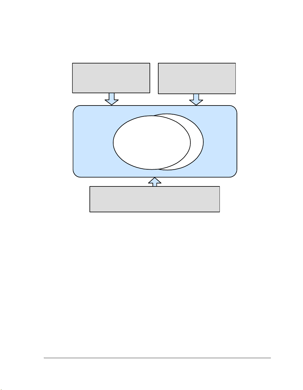
The VDK Interrupt Service Routine framework encourages you to remove
specific knowledge of hardware from the algorithms encapsulated in
threads (see Figure 1-2). Interrupts relay information to threads through
signals to device drivers or directly to threads. Using signals to connect
hardware to the algorithms allows the kernel to schedule threads based on
asynchronous events.
1-8 VisualDSP++ 3.5 Kernel (VDK) User’s Guide
for 16-bit Processors
Page 37
Introduction to VDK
Kernel
• init()
Function at Boot Time
Communication Manager
MyDevice::DispatchFunction()
Dispatc h ID:
Interrupt Service Routine
•
VDK_ISR_ACTIVATE_DEVICE_()
Application Algorithm
Device Driver
•kIO_Init
•kIO_Activate
• kIO_Ope n
•kIO_Close
• kIO_SyncRead
• kIO_SyncWrite
•kIO_IOCtl
Macr o
• OpenDevice()
APIs:
• CloseDevice( )
• SyncRead()
•
•
SyncWrite()
DeviceIO Ctl()
(Thread)
Figure 1-2. Device Drivers Entry Points
The VDK run-time environment can be thought of as a bridge between
two domains, the thread domain and the interrupt domain. The interrupt
domain services the hardware with minimal knowledge of the algorithms,
and the thread domain is abstracted from the details of the hardware.
Device drivers and signals bridge the two domains. For more information,
see “Threads” on page 3-1.
Thread Domain with Software Scheduling
The thread domain runs under a C/C++ run-time model. The prioritized
execution is maintained by a software scheduler with full context switching. Threads should have little or no direct knowledge of the hardware;
VisualDSP++ 3.5 Kernel (VDK) User’s Guide 1-9
for 16-bit Processors
Page 38

Thread and Hardware Interaction
rather, threads should request resources and then wait for them to become
available. Threads are granted processor time based on their priority and
requested resources. Threads should minimize time spent in critical and
unscheduled regions to avoid short-circuiting the scheduler and interrupt
controller.
Interrupt Domain with Hardware Scheduling
The interrupt domain runs outside the C/C++ run-time model. The prioritized execution is maintained by the hardware interrupt controller. ISRs
should be as small as possible. They should only do as much work as is
necessary to acknowledge asynchronous external events and to allow
peripherals to continue operations in parallel with the processor. ISRs
should only signal that more processing can occur and leave the processing
to threads. For more information, see “Interrupt Service Routines” on
page 3-46.
Device Drivers
Interrupt Service Routines can communicate with threads directly using
signals. Alternatively, an interVisualDSP++ 3.5 Kernel (VDK) User’s
Guidecomplex device-specific functionality that is abstracted from the
algorithm. A device driver is a single function with multiple entry conditions and domains of execution. For more information, see “Device
Drivers” on page 3-51.
1-10 VisualDSP++ 3.5 Kernel (VDK) User’s Guide
for 16-bit Processors
Page 39

2 CONFIGURATION AND
DEBUGGING OF VDK
PROJECTS
This chapter contains information about the VisualDSP++ Integrated
Development and Debugging Environment (IDDE) support for VDK
enabled projects. You can access VDK components and services through
the set of menus, commands, and windows in the IDDE.
If you are new to VisualDSP++ application development software, we recommend that you start with the VisualDSP++ 3.5 Getting Started Guide
for your target processor family.
The IDDE support for the VDK can be broken into two areas:
• “Configuring VDK Projects” on page 2-1
• “Debugging VDK Projects” on page 2-3
Configuring VDK Projects
VisualDSP++ is extended to manage all of the VDK components. You
start developing a VDK based application by creating a set of source files.
The IDDE automatically generates a source code framework for each user
requested kernel object. Use the interface to supply the required information for these objects.
For specific procedures on how to set up VDK system parameters or how
to create, modify, or delete a VDK component, refer to the VisualDSP++
online Help. Following the online procedures ensures your VDK projects
VisualDSP++ 3.5 Kernel (VDK) User’s Guide 2-1
for 16-bit Processors
Page 40

Configuring VDK Projects
build consistently and accurately with minimal project management. The
process reduces development time and allows you to concentrate on algorithm development.
Linker Description File
When a new project makes use of the kernel, a reference to a VDK-specific
default Linker Description File (
will be copied to your project directory to allow you to modify it to suit
your individual hardware configurations.
.LDF) is added to the project. This file
Thread Safe Libraries
Just as user threads must be reentrant, special “thread safe” versions of the
standard C and C++ libraries are included for use with the VDK. The
default .LDF included in VDK projects links with these libraries. If you
modify your Linker Description File, ensure that the file links with the
thread safe libraries. Your project’s LDF resides in the Linker Files folder
and is accessible via the Project tab of the Project window in
VisualDSP++.
Header Files for the VDK API
When a VDK project is created in the development environment, one of
the automatically generated files in the project directory is
header file contains enumerations for every user defined object in the
development environment and all VDK API declarations. Your source
files must include vdk.h to access any kernel services.
2-2 VisualDSP++ 3.5 Kernel (VDK) User’s Guide
vdk.h. This
for 16-bit Processors
Page 41

Configuration and Debugging of VDK Projects
Debugging VDK Projects
Debugging embedded software is a difficult task. To help offset the initial
difficulties present in debugging VDK enabled projects, the kernel offers
special instrumented builds.
Instrumented Build Information
When building a VDK project, you have an option to include instrumentation in your executable by choosing Full Instrumentation as the
instrumentation level in the Kernel tab of the Project window. An instrumented build differs from a release or non-instrumented build because the
build includes extra code for thread statistic logging. In addition, an
instrumented build creates a circular buffer of important system events.
The extra logging introduces slight overhead in thread switches and certain API calls but helps you to trace system activities.
VDK State History Window
The VDK logs user defined events and certain system state changes in a
circular buffer. An event is logged in the history buffer with a call to
LogHistoryEvent(). The call to LogHistoryEvent() logs four data values:
the ThreadID of the calling thread, the tick when the call happened, the
enumeration, and a value that is specific to the enumeration. Enumerations less than zero are reserved for use by the VDK. For more
information about the history enumeration type, see HistoryEnum
on page 4-18.
Using the history log, the IDDE displays a graph of running threads and
system state changes in the State History window. Note that the data displayed in this window is only updated at halt. The State History window,
the Thread Status and Thread Event legends are described in detail in the
online Help.
VisualDSP++ 3.5 Kernel (VDK) User’s Guide 2-3
for 16-bit Processors
Page 42

Debugging VDK Projects
Target Load Graph Window
Instrumented VDK builds allow you to analyze the average load of the
processor over a period of time. The calculated load is displayed in the
Target Load graph window. Although the calculation is not exact, the
graph helps you to estimate the utilization level of the processor. Note
that the information is updated at halt.
The Target Load graph shows the percent of time the target spent in the
idle thread. A load of 0% means the VDK spent all of its time in the idle
thread. A load of 100% means the target did not spend any time in the
idle thread. Load data is processed using a moving window average. The
load percentage is calculated for every clock tick, and all the ticks are averaged. The following formula is used to calculate the percentage of
utilization for every clock tick.
Load = 1 – (# of times idle thread ran this tick) / (# of threads
run this tick)
For more information about the Target Load graph, refer to the online
Help.
VDK Status Window
Besides history and processor load information, an instrumented build
collects statistics for relevant VDK components, such as when a thread
was created, last run, the number of times run, etc. This data is displayed
in the Status window and is updated at halt.
For more information about the VDK Status window, refer to the online
Help.
2-4 VisualDSP++ 3.5 Kernel (VDK) User’s Guide
for 16-bit Processors
Page 43

Configuration and Debugging of VDK Projects
General Tips
Even with the data collection features built into the VDK, debugging
thread code is a difficult task. Due to the fact that multiple threads in a
system are interacting asynchronously with device drivers, interrupts, and
the idle thread, it can become difficult to track down the source of an
error.
Unfortunately, one of the oldest and easiest debugging methods—inserting breakpoints—can have uncommon side effects in VDK projects. Since
multiple threads (either multiple instantiations of the same thread type or
different threads of different thread types) can execute the same function
with completely different contexts, the utilization of non-thread-aware
breakpoints is diminished. One possible workaround involves inserting
some ‘thread-specific’ breakpoints:
if (VDK_GetThreadID() == <thread_with_bug>)
{
<some statement>; /* Insert breakpoint */
}
Kernel Panic
When VDK detects an error that cannot be handled by dispatching a
thread error, it calls an internal function called KernelPanic(). By default,
this function loops forever so that users can determine that a problem has
occurred and to provide information to facilitate debugging.
Panic()
intended location.
disables interrupts on entry to ensure that execution loops in the
KernelPanic() can be overridden by users in order to
handle these types of errors differently, for example resetting the
hardware.
To allow users to determine the cause of the panic VDK sets up the following variables.
VDK::PanicCode VDK::g_KernelPanicCode
VisualDSP++ 3.5 Kernel (VDK) User’s Guide 2-5
for 16-bit Processors
Kernel-
Page 44

Debugging VDK Projects
VDK::SystemError VDK::g_KernelPanicError
int VDK::g_KernelPanicValue
int VDK::g_KernelPanicPC
• g_KernelPanicCode indicates the reason why VDK needed to raise
a Kernel Panic. For more information on the possible values of this
variable see “PanicCode” on page 4-32.
• g_KernelPanicError indicates in more detail the cause of the error.
For example, if g_KernelPanicCode indicates a boot error,
g_KernelPanicError specifies if the boot problem is in a sema-
phore, device flag, and so on. For more information, see
“SystemError” on page 4-40.
• g_KernelPanicValue is a value whose meaning is determined by the
error enumeration. For example, if the problem is creating the boot
thread with ID 4, g_KernelPanicValue is 4.
• g_KernelPanicPC provides the address that produced the Kernel
Panic.
2-6 VisualDSP++ 3.5 Kernel (VDK) User’s Guide
for 16-bit Processors
Page 45

3 USING VDK
This chapter describes how the VDK implements the general concepts
described in Chapter 2, “Introduction to VDK”. For information about
the kernel library, see Chapter 5, “VDK API Reference”.
The following sections provide information about the operating system
kernel components and operations.
• “Threads” on page 3-1
• “Scheduling” on page 3-9
• “Signals” on page 3-15
• “Interrupt Service Routines” on page 3-46
• “I/O Interface” on page 3-51
• “Memory Pools” on page 3-68
• “Multiple Heaps” on page 3-69
• “Thread Local Storage” on page 3-70
Threads
When designing an application, you partition it into threads, where each
thread is responsible for a piece of the work. Each thread operates independently of the others. A thread performs its duty as if it has its own
processor but can communicate with other threads.
VisualDSP++ 3.5 Kernel (VDK) User’s Guide 3-1
for 16-bit Processors
Page 46

Threads
Thread Types
You do not directly define threads; instead, you define thread types. A
thread is an instance of a thread type and is similar to any other user
defined type.
You can create multiple instantiations of the same thread type. Each
instantiation of the thread type has its own stack, state, priority, and other
local variables. In order to distinguish between different instances of the
same thread type an 'initializer' value can be passed to a boot thread (see
online Help for further information). Each thread is individually identified by its ThreadID, a handle that can be used to reference that thread in
kernel API calls. A thread can gain access to its ThreadID by calling
GetThreadID(). A ThreadID is valid for the life of the thread—once a
thread is destroyed, the ThreadID becomes invalid.
Old ThreadIDs are eventually reused, but there is significant time
between a thread’s destruction and the ThreadID reuse: other threads
have to recognize that the original thread is destroyed.
Thread Parameters
When a thread is created, the system allocates space in the heap to store a
data structure that holds the thread-specific parameters. The data structure contains internal information required by the kernel and the thread
type specifications provided by the user.
Stack Size
Each thread has its own stack. The full C/C++ run-time model, as specified in the appropriate VisualDSP++ 3.5 C/C++ Compiler and Library
Manual, is maintained on a per thread basis. It is your responsibility to
assure that each thread has enough room on its stack for all function calls’
return addresses and passed parameters appropriate to the particular
3-2 VisualDSP++ 3.5 Kernel (VDK) User’s Guide
for 16-bit Processors
Page 47

Using VDK
run-time model, user code structure, use of libraries, etc. Stack overflows
do not generate an exception, so an undersized stack has the potential to
cause difficulties when reproducing bugs in your system.
Priority
Each thread type specifies a default priority. Threads may change their
own (or another thread’s) priority dynamically using the SetPriority() or
ResetPriority() functions. Priorities are predefined by the kernel as an enu-
meration of type Priority with a value of
kPriority1 being the highest
priority (or the first to be scheduled) in the system. The priority enumeration is set up such that kPriority1 > kPriority2 > …. The number of
priorities is limited to the processor’s word size minus two.
Required Thread Functionality
Each thread type requires five particular functions to be declared and
implemented. Default null implementations of all five functions are provided in the templates generated by the VisualDSP++ development
environment. The thread’s run function is the entry point for the thread.
For many thread types, the thread’s run and error functions are the only
ones in the template you need to modify. The other functions allocate and
free up system resources at appropriate times during the creation and
destruction of a thread.
Run Function
The run function—called Run() in C++ and RunFunction() in C/assembly
implemented threads—is the entry point for a fully constructed thread;
Run() is roughly equivalent to main() in a C program. When a thread’s
run function returns, the thread is moved to the queue of threads waiting
to free their resources. If the run function never returns, the thread
remains running until destroyed.
VisualDSP++ 3.5 Kernel (VDK) User’s Guide 3-3
for 16-bit Processors
Page 48

Threads
Error Function
The thread’s error function is called by the kernel when an error occurs in
an API call made by the thread. The error function passes a description of
the error in the form of an enumeration (see SystemError on page 4-40 for
more details). It also can pass an additional piece of information whose
exact definition depends on the error enumeration. A thread’s default
error-handling behavior makes VDK go into Kernel Panic. See “Error
Handling Facilities” on page 3-8 for more information about error han-
dling in the VDK.
Create Function
The create function is similar to the C++ constructor. The function provides an abstraction used by the kernel APIs CreateThread() and
CreateThreadEx() to enable dynamic thread creation. The create function
is the first function called in the process of constructing a thread; it is also
responsible for calling the thread’s init function/constructor. Similar to
the constructor, the create function executes in the context of the thread
that is spawning a new thread by calling CreateThread() or CreateTh-
readEx(). The thread being constructed does not have a run-time context
fully established until after these functions complete.
A create function calls the constructor for the thread and ensures that all
of the allocations that the thread type required have taken place correctly.
If any of the allocations failed, the create function deletes the partially created thread instantiation and returns a null pointer. If the thread has been
constructed successfully, the create function returns the pointer to the
thread. A create function should not call DispatchThreadError() because
CreateThread() and CreateThreadEx() handle error reporting to the call-
ing thread when the create function returns a null pointer.
3-4 VisualDSP++ 3.5 Kernel (VDK) User’s Guide
for 16-bit Processors
Page 49

Using VDK
The create function is exposed completely in C++ source templates. For C
or assembly threads, the create function appears only in the thread’s
header file. If the thread allocates data in
InitFunction(), you need to
modify the create function in the thread’s header to verify that the allocations are successful and delete the thread if not.
A thread of a certain thread type can be created at boot time by specifying
a boot thread of the given thread type in the development environment.
Additionally, if the number of threads in the system is known at build
time, all the threads can be boot threads.
Init Function/Constructor
The InitFunction() (in C/assembly) and the constructor (in C++) provide a place for a thread to allocate system resources during the dynamic
thread creation. A thread uses malloc (or new) when allocating the thread’s
local variables. A thread’s init function/constructor cannot call any VDK
APIs since the function is called from within a different thread’s context.
Destructor
The destructor is called by the system when the thread is destroyed. A
thread can do this explicitly with a call to DestroyThread(). The thread
can also be destroyed if it runs to completion by reaching the end of its
run function and falling out of scope. In all cases, you are responsible for
freeing the memory and other system resources that the thread has
claimed. Any memory allocated with
malloc or new in the constructor
should be released with a corresponding call to free or delete in the
destructor.
A thread is not necessarily destroyed immediately when DestroyThread()
is called. DestroyThread() takes a parameter that provides a choice of priority as to when the thread’s destructor is called. If the second parameter,
inDestroyNow, is FALSE, the thread is placed in a queue of threads to be
cleaned up by the idle thread, and the destructor is called at a priority
lower than that of any user threads. While this scheme has many advan-
VisualDSP++ 3.5 Kernel (VDK) User’s Guide 3-5
for 16-bit Processors
Page 50

Threads
tages, it works as, in essence, the background garbage collection. This is
not deterministic and presents no guarantees of when the freed resources
are available to other threads.
If the
inDestroyNow argument is passed to DestroyThread() with a value
of TRUE, the destructor is called immediately. This assures the resources are
freed when the function returns, but the destructor is effectively called at
the priority of the currently running thread even if a lower priority thread
is being destroyed. It should be noted that DestroyThread() runs on the
stack of the calling thread. Therefore, if a thread calls DestroyThread() in
order to destroy itself, even if inDestroyNow is set to TRUE, the freeing of
the thread’s resources needs to be performed by the Idle Thread.
Writing Threads in Different Languages
The code to implement different thread types may be written in C, C++,
or assembly. The choice of language is transparent to the kernel. The
development environment generates well commented skeleton code for all
three choices.
One of the key properties of threads is that they are separate instances of
the thread type templates—each with a unique local state. The mechanism
for allocating, managing, and freeing thread local variables varies from
language to language.
C++ Threads
C++ threads have the simplest template code of the three supported languages. User threads are derived classes of the abstract base class
VDK::Thread. C++ threads have slightly different function names and
include a
Create() function as well a constructor.
3-6 VisualDSP++ 3.5 Kernel (VDK) User’s Guide
for 16-bit Processors
Page 51

Using VDK
Since user thread types are derived classes of the abstract base class
VDK::Thread, member variables may be added to user thread classes in the
header as with any other C++ class. The normal C++ rules for object scope
apply so that threads may make use of public, private, and static members. All member variables are thread-specific (or instantiation-specific).
Additionally, calls to VDK APIs in C++ are different from C and assembly
calls. All VDK APIs are in the VDK namespace. For example, a call to Cre-
ateThread() in C++ is VDK::CreateThread(). We do not recommend
exposing the entire VDK namespace in your C++ threads with the using
keyword.
C and Assembly Threads
Threads written in C rely on a C++ wrapper in their generated header file
but are otherwise ordinary C functions. C thread function implementations are compiled without the C++ compiler extensions.
In C and assembly programming, the state local to the thread is accessed
through a handle (a pointer to a pointer) that is passed as an argument to
each of the four user thread functions. When more than a single word of
state is needed, a block of memory is allocated with malloc() in the thread
type’s InitFunction(), and the handle is set to point to the new structure.
Each instance of the thread type allocates a unique block of memory, and
when a thread of that type is executing, the handle references the correct
memory reference. Note that, in addition to being available as an argument to all functions of the thread type, the handle can be obtained at any
time for the currently running thread using the API GetThreadHandle().
InitFunction() and DestroyFunction() implementations for a
The
thread should not call GetThreadHandle() but should instead use the
parameter passed to these functions, as they do not execute in the context
of the thread being initialized or destroyed.
VisualDSP++ 3.5 Kernel (VDK) User’s Guide 3-7
for 16-bit Processors
Page 52

Threads
Global Variables
VDK applications can use global variables as normal variables. In C or
C++, a variable defined in exactly one source file is declared as
extern in
other files in which that variable is used. In assembly, the .GLOBAL declaration exposes a variable outside a source file, and the .EXTERN declaration
resolves a reference to a symbol at link time.
You need to plan carefully how global variables are to be used in a multithreaded system. Limit access to a single thread (a single instantiation of a
thread type) whenever possible to avoid reentrancy problems. Critical
and/or unscheduled regions should be used to protect operations on global
entities that can potentially leave the system in an undefined state if not
completed atomically.
Error Handling Facilities
The VDK includes an error-handling mechanism that allows you to define
behavior independently for each thread type. Each function call in Chapter 5, “VDK API Reference”, lists the error codes that may result. For
information on the specific error code, refer to SystemError on page 4-40.
The assumption underlying the error-handling mechanism in VDK is that
all function calls normally succeed and, therefore, do not require an
explicit error code to be returned and verified by the calling code. The
VDK’s method differs from common C programming convention in
which the return value of every function call must be checked to assure
that the call has succeeded without an error. While that model is widely
used in conventional systems programming, real time embedded system
function calls rarely, if ever, fail. When an error does occur, the system
calls the user implemented
ErrorFunction(). You can call GetLastThread-
Error() to obtain an enumeration that describes the error condition. You
can also call GetLastThreadErrorValue() to obtain an additional descriptive value whose definition depends on the enumeration. The thread’s
ErrorFunction() should check if the value returned by GetLastThreadEr-
ror() is one that can be handled intelligently and can perform the
3-8 VisualDSP++ 3.5 Kernel (VDK) User’s Guide
for 16-bit Processors
Page 53

Using VDK
appropriate operations. Any enumerated errors that the thread cannot
handle must be passed to the default thread error function, which then
raises Kernel Panic. For instructions on how to pass an error to the error
function, see comments included in the generated thread code.
Scheduling
The scheduler’s role is to ensure that the highest priority ready thread is
allowed to run at the earliest possible time. The scheduler is never invoked
directly by a thread but is executed whenever a kernel API—called from
either a thread or an ISR—changes the highest priority thread. The scheduler is not invoked during critical or unscheduled regions, but can be
invoked immediately at the close of either type of protected region.
Ready Queue
The scheduler relies on an internal data structure known as the ready
queue. The queue holds references to all threads that are not blocked or
sleeping. All threads in the ready queue have all resources needed to run;
they are only waiting for processor time. The exception is the currently
running thread, which remains in the ready queue during execution.
The ready queue is called a queue because it is arranged as a prioritized
FIFO buffer. That is, when a thread is moved to the ready queue, it is
added as the last entry at its priority. For example, there are four threads
in the ready queue at the priorities
kPriority7, and an additional thread is made ready with a priority of
kPriority5 (see Figure 3-1).
kPriority3, kPriority5, and
The additional thread is inserted after the old thread with the priority of
kPriority5 but before the thread with the priority of kPriority7.
Threads are added to and removed from the ready queue in a fixed number of cycles regardless of the size of the queue.
VisualDSP++ 3.5 Kernel (VDK) User’s Guide 3-9
for 16-bit Processors
Page 54
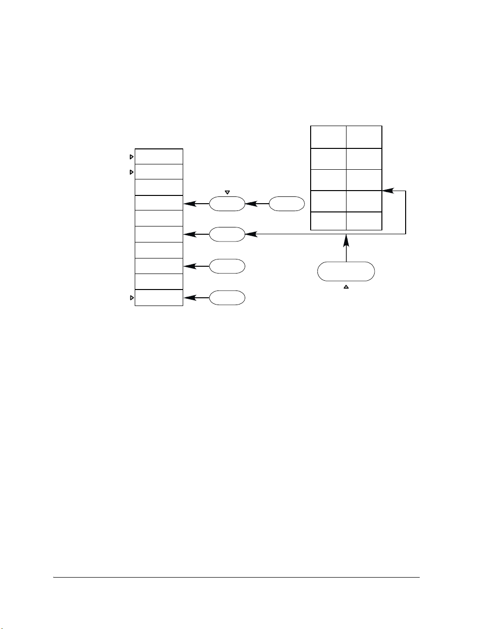
Scheduling
Priority List
(Listof Pointers)
reserved
highest
lowest, where
nisdataword
size-2
kPriority0
kPriority1
kPriority2
kPriority3
kPriority4
kPriority5
kPriority6
kPriority7
.
.
.
kPriorityN
Running Thread
Thread 1
Thread 2
Thread 3
IDLE
Figure 3-1. Ready Queue
Scheduling Methodologies
Ready Queue
(ordered by priority,then FIFO)
Thread 1
Thread 4
Thread 2
Thread 4
Thread 3
IDLE
(priority kPriority5)
new thread
of ready status
kPriority3
kPriority3
kPriority5
kPriority7
kPriorityN
Thread 5
The VDK always operates as a preemptive kernel. However, you can take
advantage of a number of modes to expand the options for simpler or
more complex scheduling in your applications.
Cooperative Scheduling
Multiple threads may be created at the same priority level. In the simplest
scheduling scheme, all threads in the system are given the same priority,
and each thread has access to the processor until it manually yields control. This arrangement is called cooperative multithreading. When a thread
is ready to defer to the next thread at the same priority level, the thread
can do so by calling the Yield() function, placing the currently running
thread at the end of the list. In addition, any system call that causes the
3-10 VisualDSP++ 3.5 Kernel (VDK) User’s Guide
for 16-bit Processors
Page 55

Using VDK
currently running thread to block would have a similar result. For example, if a thread pends on a signal that is not currently available, the next
thread in the queue at that priority starts running.
Round-robin Scheduling
Round-robin scheduling, also called time slicing, allows multiple threads
with the same priority to be given processor time automatically in fixed
duration allotments. In the VDK, priority levels may be designated as
round-robin mode at build time and their period specified in system ticks.
Threads at that priority are run for that duration, as measured by the
number of VDK Ticks. If the thread is preempted by a higher priority
thread for a significant amount of time, the time is not subtracted from
the time slice. When a thread’s round-robin period completes, it is moved
to the end of the list of threads at its priority in the ready queue. Note that
the round-robin period is subject to jitter when threads at that priority are
preempted.
Preemptive Scheduling
Full preemptive scheduling, in which a thread gets processor time as soon as
it is placed in the ready queue if it has a higher priority than the running
thread, provides more power and flexibility than pure cooperative or
round-robin scheduling.
The VDK allows the use of all three paradigms without any modal configuration. For example, multiple non-time-critical threads can be set to a
low priority in the round-robin mode, ensuring that each thread gets processor time without interfering with time critical threads. Furthermore, a
thread can yield the processor at any time, allowing another thread to run.
A thread does not need to wait for a timer event to swap the thread out
when it has completed the assigned task.
VisualDSP++ 3.5 Kernel (VDK) User’s Guide 3-11
for 16-bit Processors
Page 56

Scheduling
Disabling Scheduling
Sometimes it is necessary to disable the scheduler when manipulating global entities. For example, when a thread tries to change the state of more
than one signal at a time, the thread can enter an unscheduled region to
ensure that all updates occur atomically. Unscheduled regions are sections
of code that execute without being preempted by a higher priority thread.
Note that interrupts are serviced in an unscheduled region, but the same
thread runs on return to the thread domain. Unscheduled regions are
entered through a call to PushUnscheduledRegion(). To exit an unscheduled region, a thread calls PopUnscheduledRegion().
Unscheduled regions (in the same way as critical regions, covered in
“Enabling and Disabling Interrupts” on page 3-46) are implemented with
a stack. Using nested critical and unscheduled regions allows you to write
code that activates a region without being concerned about the region
context when a function is called. For example:
void My_UnscheduledFunction()
{
VDK_PushUnscheduledRegion();
/* In at least one unscheduled region, but
this function can be used from any number
of unscheduled or critical regions */
/* ... */
VDK_PopUnscheduledRegion();
}
void MyOtherFunction()
{
VDK_PushUnscheduledRegion();
/* ... */
/* This call adds and removes one unscheduled region */
My_UnscheduledFunction();
/* The unscheduled regions are restored here */
/* ... */
3-12 VisualDSP++ 3.5 Kernel (VDK) User’s Guide
for 16-bit Processors
Page 57

Using VDK
VDK_PopUnscheduledRegion();
}
An additional function for controlling unscheduled regions is PopNeste-
dUnscheduledRegions(). This function completely pops the stack of all
unscheduled regions. Although the VDK includes PopNestedUnschedule-
dRegions(), applications should use the function infrequently and balance
regions correctly.
Entering the Scheduler From API Calls
Since the highest priority ready thread is the running thread, the scheduler
needs to be called only when a higher priority thread becomes ready.
Because a thread interacts with the system through a series of API calls,
the points at which the highest priority ready thread may change are well
defined. Therefore, a thread invokes the scheduler only at these times, or
whenever it leaves an unscheduled region.
Entering the Scheduler From Interrupts
ISRs communicate with the thread domain through a set of APIs that do
not assume any context. Depending on the system state, an ISR API call
may require the scheduler to be executed. The VDK reserves the lowest
priority software interrupt to handle the reschedule process.
If an ISR API call affects the system state, the API raises the lowest priority software interrupt. When the lowest priority software interrupt is
scheduled to run by the hardware interrupt dispatcher, the interrupt
reduces to subroutine and enters the scheduler. If the interrupted thread is
not in an unscheduled region and a higher priority thread has become
ready, the scheduler swaps out the interrupted thread and swaps in the
new highest priority ready thread. The lowest priority software interrupt
respects any unscheduled regions the running thread is in. However, interrupts can still service device drivers, post semaphores, etc. On leaving the
VisualDSP++ 3.5 Kernel (VDK) User’s Guide 3-13
for 16-bit Processors
Page 58

Scheduling
unscheduled region, the scheduler is run again, and the highest priority
ready thread will become the running thread (see Figure 3-2 on
page 3-14).
CreateThread()
Thread is Instantiated
- PostSemaphore()
Return from Interrupt
(no longer Highest
Priority Ready Thread)
DestroyThread()
Thread is Destroyed
INTERRUPTED
Nested Interrupts
- PostD eviceFlag()
- PostMessage()
-Sleep()ends
- T hread pends on the
event th at becomes
- Round-robin period
(remains Highest Priority Ready Thread)
Figure 3-2. Thread State Diagram
READY
TRUE
starts
BLOCKED
- PendSemaphore()
- PendDeviceFla g()
-PendEvent()
- PendMessage()
-Sleep()
- Round-robin peri od ends
Interrupt
Return from Inte rrupt
Highest Priority
Ready Thread
RUNNING
Idle Thread
The idle thread is a predefined, automatically created thread that has a priority lower than that of any user threads. Thus, when there are no user
threads in the ready queue, the idle thread runs. The only substantial work
performed by the idle thread is the freeing of resources of threads that
3-14 VisualDSP++ 3.5 Kernel (VDK) User’s Guide
for 16-bit Processors
Page 59

Using VDK
have been destroyed. In other words, the idle thread handles destruction
of threads that were passed to DestroyThread() with a value of
inDestroyNow. Depending on the platform, it may be possible to custom-
ize certain properties of the Idle thread, such as its stack size and the heap
from which all its memory requirements (including the Idle thread stack)
are allocated (see online Help for further details). On Blackfin it is necessary to ensure that the Idle thread's stack is a sufficient size to allow for the
requirements of any Interrupt Service Routines (see “Thread Stack Usage
by Interrupts” on page A-7 for further information).
The time spent in threads other than the idle thread is shown plotted as a
percentage over time on the Target Load tab of the State History window
in VisualDSP++. See “VDK State History Window” on page 2-3 and
online Help for more information about the State History window.
FALSE for
Signals
Threads have four different methods for communication and
synchronization:
• “Semaphores” on page 3-16
• “Messages” on page 3-21
• “Events and Event Bits” on page 3-38
• “Device Flags” on page 3-45
Each communication method has a different behavior and use. A thread
pends on any of the four types of signals, and if a signal is unavailable, the
thread blocks until the signal becomes available or (optionally) a timeout
is reached.
VisualDSP++ 3.5 Kernel (VDK) User’s Guide 3-15
for 16-bit Processors
Page 60

Signals
Semaphores
Semaphores are protocol mechanisms offered by most operating systems.
Semaphores are used to:
• Control access to a shared resource
• Signal a certain system occurrence
• Allow threads to synchronize
• Schedule periodic execution of threads
The maximum number of active semaphores and initial state of the semaphores enabled at boot time are set up when your project is built.
Behavior of Semaphores
A semaphore is a token that a thread acquires so that the thread can continue execution. If the thread pends on the semaphore and it is available
(the count value associated with the semaphore is greater than zero), the
semaphore is acquired, its count value is decremented by one and the
thread continues normal execution. If the semaphore is not available (its
count is zero), the thread trying to acquire (pend on) the semaphore
blocks until the semaphore is available, or the specified timeout occurs. If
the semaphore does not become available in the time specified, the thread
continues execution in its error function.
Semaphores are global resources accessible to all threads in the system.
Threads of different types and priorities can pend on a semaphore. When
the semaphore is posted, the thread with the highest priority that has been
waiting the longest is moved to the ready queue. If there are no threads
pending on the semaphore, its count value is incremented by one. The
count value is limited by the maximum value specified at the time of the
semaphore creation. Additionally, unlike many operating systems, VDK
semaphores are not owned. In other words, any thread is allowed to post a
3-16 VisualDSP++ 3.5 Kernel (VDK) User’s Guide
for 16-bit Processors
Page 61

Using VDK
semaphore (make it available). If a thread has requested (pended on) and
acquired a semaphore, and the thread is subsequently destroyed, the semaphore is not automatically posted by the kernel.
Besides operating as a flag between threads, a semaphore can be set up to
be periodic. A periodic semaphore is posted by the kernel every n ticks,
where n is the period of the semaphore. Periodic semaphores can be used
to ensure that a thread is run at regular intervals.
Thread’s Interaction With Semaphores
Threads interact with semaphores through the set of semaphore APIs.
These functions allow a thread to create a semaphore, destroy a semaphore, pend on a semaphore, post a semaphore, get a semaphore’s value,
and add or remove a semaphore from the periodic queue.
Pending on a Semaphore
Figure 3-3 illustrates the process of pending on a semaphore.
Thread 1continues execution
PendSemaphore()
Thread 1
Is
Semaphore
available?
(count >0)
No
Thread1 addsitself to
FIFO
Decrease
semaphore's
count
Yes
Sema phore' s List of
Pending Threads
Order by priority, then
No
Is
therea
timeout before
semaphore
becameavail-
able?
Yes
kNoTimeoutError
Yes
No
Is
set?
Thread 1's
ErrorFunction ()
iscalled
Figure 3-3. Pending on a Semaphore
VisualDSP++ 3.5 Kernel (VDK) User’s Guide 3-17
for 16-bit Processors
Page 62

Signals
Threads can pend on a semaphore with a call to PendSemaphore(). When
a thread calls PendSemaphore(), it performs one of the following:
• Acquires the semaphore, decrements its count by one, and continues execution.
• Blocks until the semaphore is available or the specified timeout
occurs.
If the semaphore becomes available before the timeout occurs or a timeout
occurs and the
kNoTimeoutError bit has been specified in the timeout
parameter, the thread continues execution; otherwise, the thread’s error
function is called and the thread continues execution. You should not call
PendSemaphore() within an unscheduled or critical region because if the
semaphore is not available, then the thread will block, but with the scheduler disabled, execution cannot be switched to another thread. Pending
with a timeout of zero on a semaphore pends without timeout.
Posting a Semaphore
Semaphores can be posted from two different scheduling domains: the
thread domain and the interrupt domain. If there are threads pending on
the semaphore, posting it moves the highest priority thread from the
semaphore’s list of pending threads to the ready queue. All other threads
are left blocked on the semaphore until their timeout occurs, or the semaphore becomes available for them. If there are no threads pending on the
semaphore, posting it increments the count value by one. If the maximum
count, which is specified when the semaphore is created, is reached, posting the semaphore has no effect.
Posting from the Thread Domain. Figure 3-4 and Figure 3-5 illustrate
the process of posting semaphores from the thread domain.
A thread can post a semaphore with a call to the PostSemaphore() API. If
a thread calls PostSemaphore() from within a scheduled region (see
Figure 3-4), and a higher priority thread is moved to the ready queue, the
thread calling PostSemaphore() is context switched out.
3-18 VisualDSP++ 3.5 Kernel (VDK) User’s Guide
for 16-bit Processors
Page 63

PostSemaphore()
Thread 1
Is
Semaphore
available?
(count>0)
Yes
No
Semaphore's List
of Pending
Threads
Order
threads
by priority,
then FIFO
Next Thread
Ready Queue
Order threads
by priority,
then FIFO
Using VDK
1). Invoke Scheduler
2). Switch out the
currentthread
3).Switch in the highest
priority pending thread
Thread 1of the
Is
highest
priority?
No
Yes
Is
Semaphore's
count <
its maximum
count?
No
Yes
Increase Semaphore's
count
Thread 1 runs
Figure 3-4. Thread Domain/Scheduled Region: Posting a Semaphore
If a thread calls PostSemaphore() from within an unscheduled region,
where the scheduler is disabled, the highest priority thread pending on the
semaphore is moved to the ready queue, but no context switch occurs (see
Figure 3-5).
Posting from the Interrupt Domain. Interrupt subroutines can also post
semaphores. Figure 3-6 on page 3-20 illustrates the process of posting a
semaphore from the interrupt domain.
An ISR posts a semaphore by calling the
VDK_ISR_POST_SEMAPHORE_() macro. The macro moves the high-
est priority thread to the ready queue and latches the low priority software
interrupt if a call to the scheduler is required. When the ISR completes
execution, and the low priority software interrupt is run, the scheduler is
VisualDSP++ 3.5 Kernel (VDK) User’s Guide 3-19
for 16-bit Processors
Page 64

Signals
PostSemaphore()
Thread 1
Is
Semaphore
available?
(count>0)
Yes
Is
Semaphore's
count <
its maximum
count?
No
No
Yes
Semaphore's List
of PendingThreads
Order
threads
by priority,
then FIFO
IncreaseSemaphore's
Next Th read
count
Ready Queue
Order threads
by priority,
then FIFO
Thread1 runs
Figure 3-5. Thread Domain/Unscheduled Region: Posting a Semaphore
VDK_ISR_POST_SEMAPH ORE_()
2). RTI
3).The lowpriority
ISR runs
4).Kernel runs
Semaphore's List
of PendingThreads
Order
threads
by pri ority,
then FIFO
5).Decrease
Semaphore‘s count
Next Thread
Ready Queue
Order threads
by priority,
then FIFO
2).Switch into the highest
priority pending thread
1).Switch out the
ISR 1
ISR 2
ISR 3
Are
therethreads
pending?
No
Is
Semaphore's
count <
its maximum
count?
No
Yes
Yes
Increase Semaphore's
count
1).Set the low priorityISR
Increase Semaphore's
Count
interruptedthread
No
Is the
interrupted
thread of the
highest
priority?
Yes
The interruptedtread runs
Figure 3-6. Interrupt Domain: Posting a Semaphore
3-20 VisualDSP++ 3.5 Kernel (VDK) User’s Guide
for 16-bit Processors
Page 65

Using VDK
run. If the interrupted thread is in a scheduled region, and a higher priority thread becomes ready, the interrupted thread is switched out and the
new thread is switched in.
Periodic Semaphores
Semaphores can also be used to schedule periodic threads. The semaphore
is posted every n ticks (where n is the semaphore’s period). A thread can
then pend on the semaphore and be scheduled to run every time the semaphore is posted. A periodic semaphore does not guarantee that the thread
pending on the semaphore is the highest priority scheduled to run, or that
scheduling is enabled. All that is guaranteed is that the semaphore is
posted, and the highest priority thread pending on that semaphore moves
to the ready queue.
Periodic semaphores are posted by the kernel during the timer interrupt at
system tick boundaries. Periodic semaphores can also be posted at any
time with a call to PostSemaphore() or
VDK_ISR_POST_SEMAPHORE_(). Calls to these functions do not
affect the periodic posting of the semaphore.
Messages
Messages are an inter-thread communication mechanism offered by many
operating systems. Messages can be used to:
• Communicate information between two threads
• Control access to a shared resource
• Signal a certain occurrence and communicate information about
the occurrence
• Allow two threads to synchronize
VisualDSP++ 3.5 Kernel (VDK) User’s Guide 3-21
for 16-bit Processors
Page 66

Signals
The maximum number of messages supported in the system is set up when
the project is built.When the maximum number of messages is non-zero, a
system-owned memory pool is created to support messaging. The properties of this memory pool should not be altered. Further information on
memory pools is given in “Memory Pools” on page 3-68.
Behavior of Messages
Messages allow two threads to communicate over logically separate channels. A message is sent on one of 15 possible channels,
kMsgChannel15. Messages are retrieved from these channels in priority
kMsgChannel1 to
order: kMsgChannel1, kMsgChannel2, ... kMsgChannel15. Each message can
pass a reference to a data buffer, in the form of a message payload, from
the sending thread to the receiving thread.
A thread creates a message (optionally associating a payload) and then
posts (sends) the message to another thread. The posting thread continues
normal execution unless the posting of the message activates a higher priority thread which is pending on (waiting to receive) the message.
A thread can pend on the receipt of a message on one or more of its channels. If a message is already queued for the thread, it receives the message
and continues normal execution. If no suitable message is already queued,
the thread blocks until a suitable message is posted to the thread, or until
the specified timeout occurs. If a suitable message is not posted to the
thread in the time specified, the thread continues execution in its error
function.
Unlike semaphores, each message always has a defined owner at any given
time, and only the owning thread can perform operations on the message.
When a thread creates a message, it owns the message until it posts the
message to another thread. The message ownership changes to the receiving thread following the post, when it is queued on one of the receiving
message’s channels. The receiving thread is now the owner of the message.
3-22 VisualDSP++ 3.5 Kernel (VDK) User’s Guide
for 16-bit Processors
Page 67

Using VDK
The only operation that can be performed on the message at this time is
pending on the message, making the message and its contents available to
the receiving thread.
A message can only be destroyed by its owner; therefore, a thread that
receives a message is responsible for either destroying or reusing a message.
Ownership of the associated payload also belongs to the thread that owns
the message. The owner of the message is responsible for the control of
any memory allocation associated with the payload.
Each thread is responsible for destroying any messages it owns before it
destroys itself. If there are any messages left queued on a thread’s receiving
channels when it is destroyed, then the system destroys the queued messages. As the system has no knowledge of the contents of the payload, the
system does not free any resources used by the payload.
Thread’s Interaction With Messages
Threads interact with messages through the set of message APIs. The
functions allow a thread to create a message, pend on a message, post a
message, get and set information associated with a message, and destroy a
message.
Pending on a Message
Figure 3-7 illustrates the process of pending on a message.
Threads can pend on a message with a call to PendMessage(), specifying
one or more channels that a message is to be received on. When a thread
calls PendMessage(), it does one of the following:
• Receives a message and continues execution
• Blocks until a message is available on the specified channel(s) or
the specified timeout occurs
VisualDSP++ 3.5 Kernel (VDK) User’s Guide 3-23
for 16-bit Processors
Page 68
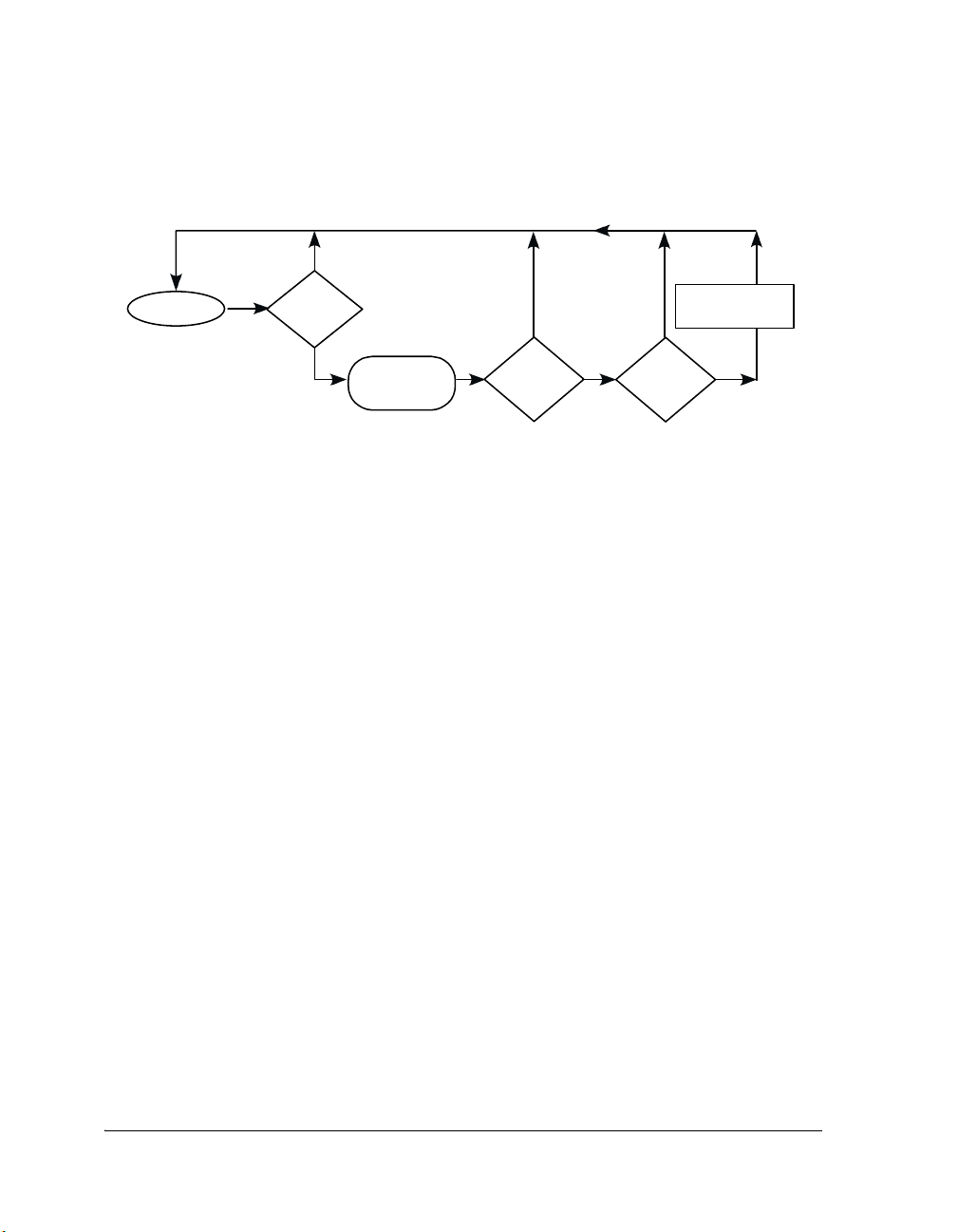
Signals
Thread 1 continues execution
Yes
PendMessage()
Thread 1
Message
available?
No
Is
Thread is removed
from Ready Queue
No
Is
there a
timeout before
Message became
available?
Yes
Yes
Function() is called
Is
kNoTimeoutError
set?
Thread 1‘s Error
No
Figure 3-7. Pending on a Message
If messages are queued on the specified channels before the timeout occurs
or a timeout occurs and the
kNoTimeoutError bit has been specified in the
timeout parameter, the thread continues normal execution; otherwise, the
thread continues execution in its error function.
Once a message has been received, you can obtain the identity of the sending thread and the channel the message was received on by calling
GetMessageReceiveInfo(). You can also obtain information about the pay-
load by calling GetMessagePayload(), which returns the type and length of
the payload in addition to its location. You should not call PendMessage()
within an unscheduled or critical region because if a message is not available, then the thread will block, but with the scheduler disabled, execution
cannot be switched to another thread. Pending with a timeout of zero on a
message pends without timeout.
Posting a Message
Posting a message sends the specified message and the reference to its payload to the specified thread and transfers ownership of the message to the
receiving thread. The details of the message payload can be specified by a
call on the SetMessagePayload() function, which allows the thread to spec-
ify the payload type, length, and location before posting the message. A
3-24 VisualDSP++ 3.5 Kernel (VDK) User’s Guide
for 16-bit Processors
Page 69
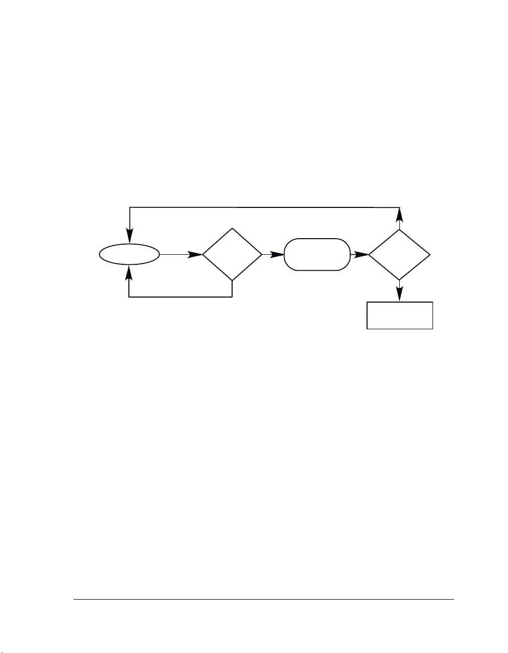
Using VDK
thread can send a message it currently owns with a call to PostMessage(),
specifying the destination thread and the channel the message is to be sent
on.
Figure 3-8 illustrates the process of posting a message from a scheduled
region.
Thread 1 continues execution
Yes
Thread 1
PostMessage()
Is the
destination
thread
unblocked by
this Message?
Yes
Destination thread
moved to
Ready Queue
Is
Thread 1
of thehighest
priority?
No
No
Invoke
Scheduler
Figure 3-8. Posting a Message From a Scheduled Region
If a thread calls PostMessage() from within a scheduled region, and a
higher priority thread is moved to the ready queue on receiving the message, then the thread calling PostMessage() is context switched out.
Figure 3-9 illustrates the process of posting a message from an unsched-
uled region.
If a thread calls PostMessage() from within an unscheduled region, even if
a higher priority thread is moved to the ready queue to receive the message, the thread that calls PostMessage() continues to execute.
VisualDSP++ 3.5 Kernel (VDK) User’s Guide 3-25
for 16-bit Processors
Page 70
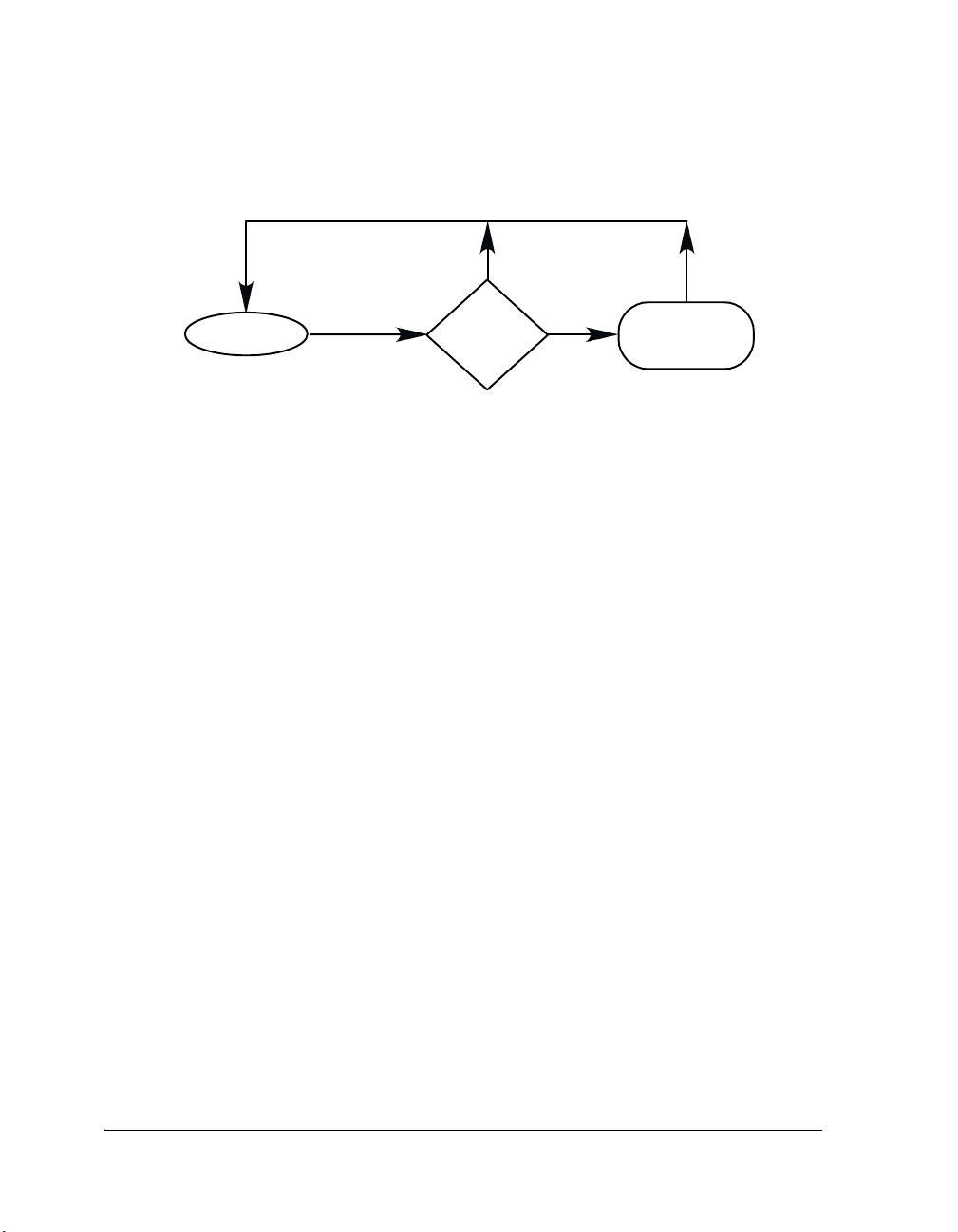
Signals
Thread 1 continues execution
No
PostMessage()
Thread 1
Is the
destination thread
unblocked by this
Message?
Yes
Destination thread
moved to
Ready Queue
Figure 3-9. Posting a Message From an Unscheduled Region
Multiprocessor Messaging
The VDK messaging functionality has been extended in VisualDSP++ 3.5
to allow messages to be passed between the processors in a multiprocessor
configuration. The APIs and corresponding behaviors are, as much as possible, the same as for intra-processor messaging, but with extensions.
Each DSP in a multiprocessor configuration is referred to as a Node and
must have its own VisualDSP++ project. This means that each node runs
its own instance of the VDK kernel and all VDK entities (such as semaphores, event bits, events, and so on, but excepting threads) are private to
that node. Each node has a unique numeric node ID, which is set in the
project's kernel tab.
Threads are uniquely identified across the multiprocessor system by
embedding the node ID as a 5-bit field within the ThreadID. The size of
this field limits the maximum number of nodes in the system to 32.
Threads are permanently located on the node where they are created —
there is no “migration” of threads between nodes.
In order for threads to be referenced on other nodes, each project in a
multiprocessor system uses the kernel tab's Import list to import the
project files for all the other nodes in the system. This makes the boot
ThreadIDs for all the projects visible and usable across the system.
3-26 VisualDSP++ 3.5 Kernel (VDK) User’s Guide
for 16-bit Processors
Page 71

Using VDK
Threads located on other nodes may then be used as destinations for the
VDK::PostMessage() and VDK::ForwardMessage() functions, though not
for any other thread-related API function.
Boot threads serve as “anchor points” for node-to-node communications,
as their identities are known at build time. In order to communicate with
dynamically-created threads on other nodes it is necessary to pass the
ThreadIDs as data between the nodes (that is, in a message payload). A
reply to an incoming message can always be sent, regardless of the identity
of the sending thread, as the sender's ID is carried in the message itself.
Boot threads can therefore be used to provide information about dynamically-created threads, but such arrangements are application-specific and
must form part of the system design.
Routing Threads (RThreads)
When a message is posted by a thread, the destination node ID (embedded
in the destination ThreadID) is examined. If it matches the node ID of
the node on which the thread is running, then the message is placed
directly into the message queue of the destination thread, exactly as in single-processor messaging. If the node IDs do not match, then the message
is passed to one of a set of Routing Threads (RThreads), which is responsible for the next stage in the process of moving the message to its
destination.
RThread takes one of two roles - Incoming or Outgoing - which is
Each
fixed at the time of its creation.
Each RThread employs a device driver, which manages the physical details
of moving messages between nodes. An Outgoing
open for writing, while an Incoming
RThread has its device open for
RThread has its device
reading.
VisualDSP++ 3.5 Kernel (VDK) User’s Guide 3-27
for 16-bit Processors
Page 72

Signals
Outgoing
RThreads are referenced via a Routing Table, which is con-
structed by VisualDSP++ at build time. When a message must be sent to a
different node, the destination node ID is used as an index into this table
to select which outgoing RThread will handle transmission of the message.
Each node must contain at least one incoming and one outgoing Rthread,
together with their corresponding device drivers. More RThreads may be
included, depending on the number of physical connections to other
nodes. However, the number of outgoing RThreads may be less than the
number of nodes in the system, so that more than one entry in the routing
table may map to the same RThread. This means that the topology of the
multiprocessor system may require that a message make more than one
“hop” to reach its final destination.
An outgoing RThread, when idle, waits for messages to be placed on any
channel of its message queue, and then transmits that message (as a Message Packet) by making one or more SyncWrite() calls to its associated
device driver. These SyncWrite() calls may block waiting I/O completion.
An incoming RThread, when idle, blocks in a SyncRead() call to its device
driver awaiting reception of a message packet. Once the packet has been
received, and expanded into a message object, the RThread forwards it to
its destination. This may involve passing the message to an outgoing
rthread if the current node is not the message's final destination.
3-28 VisualDSP++ 3.5 Kernel (VDK) User’s Guide
for 16-bit Processors
Page 73

Using VDK
The actual message objects, as referenced by particular
MessageIDs, are
each local to a particular node. When a message is transmitted between
two nodes it is only the message contents that are passed over (as a Message Packet), the message object itself is destroyed on the sending side and
recreated on the receiving side. This has a number of consequences:
• The message will usually have a different ID on the receiving side
than it did on the sending.
• Message objects that are passed to an outgoing RThread are
destroyed after transmission, and hence returned to the pool of free
messages.
• When a message packet is received by an incoming RThread, a message object must be created (from the pool of free messages).
VisualDSP++ 3.5 Kernel (VDK) User’s Guide 3-29
for 16-bit Processors
Page 74

Signals
Figure 3-10 shows the path taken by a message being sent between two
threads on different nodes (A and B), where a direct connection exists
between the two nodes.
Sending
Thread
PostMessage()
SyncWrite() SyncRead()
NODE A NODE B
CreateMessage()
Transfer
Outgoing
Rthread
DestroyMessage()
DEVICE
DRIVER
Physical Connection
(Link Port, Cluster Bus,
Internal Memory DMA)
DEVICE
DRIVER
PostMessage()
Figure 3-10. Sending Messages Between Adjacent Nodes
Incoming
RThread
Receving
Thread
3-30 VisualDSP++ 3.5 Kernel (VDK) User’s Guide
for 16-bit Processors
Page 75

Using VDK
Figure 3-11 shows a scenario where node Y was an intermediate "hop" on
the way to a third node, Z. The message is posted by Y's incoming
RThread, directly into the message queue of the routing thread for the out-
going connection.
Node X
CreateMessage()
SyncRead()
Incoming
RThread
Outgoing
RThread
Node Y
SyncWrite()
DEVICE
DRIVER
Node Z
Physical Connection
(Link Port, Cluster Bus)
DEVICE
DRIVER
PostMessage()
DestroyMessage()
Physical Connection
(Link Port, Cluster Bus)
Figure 3-11. Sending Messages between Non-adjacent Nodes via an Intermediate Node
VisualDSP++ 3.5 Kernel (VDK) User’s Guide 3-31
for 16-bit Processors
Page 76

Signals
If the message allocation by the incoming
RThread fails then a system error
is raised and execution stops on that node. This is necessary because the
alternative of “dropping” the message is unacceptable (message delivery is
defined as being reliable in VDK). There are a number of ways of avoiding
this problem:
1. Careful design of the message flow in the application, and careful
choice of priorities for the RThreads. The use of loopback (that is,
returning messages to sender rather than destroying them) may
assist with this.
2. Preallocate all messages during initialization and use loopback so
that they never need to be explicitly destroyed. The maximum messages setting (in the kernel tab) for each node must be set equal to
the total number of messages in the overall system. This ensures
that there will be no failure even in the worst case of all messages
being sent to the same node at once.
3. A counting semaphore may be installed to regulate the flow of messages into the node, using the
VDK::InstallMessageControlSemaphore() API function. The ini-
tial count of this semaphore should be set to less than or equal to
the number of free messages which are reserved for use by the
rthreads. This semaphore will be pended on prior to each message
allocation by an incoming rthread, and posted after each deallocation by an outgoing rthread. Provided that the semaphore's count
is never less than the number of free messages on the node then the
allocations will never fail. However, message flow into the node
may stall if the semaphore count falls to zero.
Option 1 requires a thorough understanding of application behavior.
Option 2 carries a memory space overhead, as more space may be reserved
for messages than is actually needed at runtime, but is the simplest solution if this is not problem. Option 3 carries a performance overhead due
3-32 VisualDSP++ 3.5 Kernel (VDK) User’s Guide
for 16-bit Processors
Page 77

Using VDK
to the semaphore pend and post operations. Additionally, if message flow
stalls, which may occur with Option 3, it may have other consequences for
the system.
Data Transfer (Payload Marshalling)
Very simple messages can be sent between nodes without interpretation,
that is, if the message information is entirely conveyed by the three words
of message data (internal payload). However, if the message actually has
an in-memory (external) payload, then the address of this payload may not
be meaningful once the message arrives on another node. In these cases
the payload must be transferred along with the message. This is done via
Payload Marshalling.
Any message type that has the MSB (sign bit) set (that is, a negative value)
is considered to be a Marshalled Type, meaning that the system expects to
allocate, deallocate and transfer the payload automatically from node to
node.
Since the organization of the payload for a particular message type is
entirely the choice of the application designer (it might be a linked-list or
a tree, rather than a plain memory block), the allocation, deallocation and
transfer of the payload is the responsibility of a Marshalling Function.
Pointers to these functions are held in a static Marshalling Table, which is
indexed using the low-order bits of the message type.
The marshalling function implements (at least) the following operations:
• Allocate and receive
• Transmit and release
Note that it is not compulsory for the marshalling function to transfer the
payload via the device driver. It may, for example, only be necessary for it
to translate the payload address from a local value to a cluster bus address,
so as to permit in-place access to the payload from another DSP. When
the payloads for a particular message type are always stored in a memory
VisualDSP++ 3.5 Kernel (VDK) User’s Guide 3-33
for 16-bit Processors
Page 78

Signals
(for example, SDRAM), which is visible to all nodes and mapped to the
same address range on each, then no marshalling is needed. The message
type can be given a non-marshalled value (that is, the sign bit is zero).
Since the most common form of marshalled payload is likely to be a plain
memory block allocated either from a heap or from a VDK memory pool,
VDK provides built-in Standard Marshalling functions to handle these
cases. The more complex cases (linked data structures, shared memory,
and so on) require user-written Custom Marshalling functions.
Marshalling functions are called from the routing threads, and are passed
these arguments:
• Marshalling code — indicates which operation is to be performed
• A pointer to the formatted message packet, which includes payload
type, size and address — for input and output
• Device descriptor — identifies the VDK device driver for the
connection
• Heap index or PoolID — used by standard marshalling
• I/O timeout duration (usually set to zero, for indefinite wait)
For transmission, the marshalling function is also responsible for first
transmitting the message packet. This is to give the opportunity for the
marshalling function to modify the payload attributes prior to transmission. For example, if the payload is to be accessed in-place across the
cluster bus (on TigerSHARC) then node-specific addresses must be translated to the global address space and back.
The marshalling functions execute in the context of the routing threads.
SyncRead() or SyncWrite() calls made by the marshalling functions will
(or may) cause the threads to block awaiting I/O completion, however the
original sending thread(s) will not be blocked. In this way the routing
threads act as a buffer between user threads and the interprocessor message
transfer mechanism.
3-34 VisualDSP++ 3.5 Kernel (VDK) User’s Guide
for 16-bit Processors
Page 79

Using VDK
Note that it is not strictly necessary for the marshalling function to actually transfer the data, in certain circumstances it may be sufficient for it
merely to perform the allocations and deallocations. An example of where
this may be useful is when using message loopback. The message may be
returned to the sender after changing its payload type to one whose marshalling function simply frees the payload when the message is transmitted
and allocates a payload when the message is received. This avoids the overhead of transferring data which is no longer of interest but allows the
payload to still be automatically managed by the system. The only added
complexity is the need for two marshalled types instead of one, and for the
user threads to change the payload type between the two according to
whether the message is “full” or “empty”.
When defining a marshalled payload type in the kernel tab, the user can
select either standard or custom marshalling. For standard marshalling the
choice must also be made between heap or pool marshalling, according to
whether the payloads will be allocated from a C/C++ heap (using the
VisualDSP++ multiple heap API extensions) or a VDK memory pool. The
heap or PoolID must also be specified. For custom marshalling the name
of the marshalling function must be supplied, and a source module containing a skeleton of the marshalling function is automatically created. It
is then the user's task to add the code that allocates and deallocates, and
reads and writes, the actual payload
VisualDSP++ 3.5 Kernel (VDK) User’s Guide 3-35
for 16-bit Processors
Page 80

Signals
Device Drivers for Messaging
Device drivers employed in message transfer must provide certain properties which are assumed in the design of the routing threads:
• Synchronous operation - once a write call returns, the caller knows
that the data has been sent.
• Flow control - no data will be lost if a write (by the sender) is initiated before the corresponding read (by the receiver).
• Reliable delivery - all data sent (written) will be received (read) at
the other side.
As mentioned above, the contents of messages are written to and read
from the device driver as Message Packets. These packets are 16 bytes (128
bits) in size and are always read and written by a single operation of that
size. Device drivers can therefore be optimized for these transfers, as they
will be the most frequent case, although other sizes must still be
supported.
As well as the message packets the device driver must also transfer the message payloads which are written and read by the marshalling functions. It
is the responsibility of the application designer to ensure that the marshalling functions and the device drivers operate together correctly, that is that
any transfer size or alignment restrictions imposed by the drivers are met
by the payloads. This is also true of marshalled payload types using standard marshalling, the sizes and alignments of the heap or memory pool
blocks must be acceptable to the messaging device drivers.
Where a bidirectional hardware device (such as a link port on SHARC or
TigerSHARC) is managed by a single device driver instance on each of the
two nodes that it connects, then it is necessary for the device driver to permit itself to be opened by both an incoming and an outgoing routing
thread. A generalized multiple-open capability is not required, the ability
to be simultaneously open once for reading and once for writing (some-
3-36 VisualDSP++ 3.5 Kernel (VDK) User’s Guide
for 16-bit Processors
Page 81

Using VDK
times known as a “split open”) is sufficient. Alternatively, for some devices
it may be preferable to create two device driver instances on each node, so
that the hardware appears as two unidirectional connections.
Routing Topology
Application designers must choose the routing structure for a particular
application. This choice is closely linked to the organization of the target
hardware.
At one extreme, the ideal situation is to have a direct connection between
each node. In such a configuration no through-routing is be required, that
is each message post requires only one “hop”. This can be achieved for a
small numbers of nodes (between two and five), however, the number of
connections quickly becomes prohibitive as the number of nodes
increases.
At the other extreme, the minimum number of connections required is
one incoming and one outgoing per node. This is sufficient to allow the
nodes to be connected in a simple “ring” configuration. However, a message post may require many “hops” if the sender and receiver are widely
separated on the ring. If the connections are bidirectional (for example,
link ports) and each node has two, then a bidirectional ring – with messages circulating in both directions – is possible.
Between these two extremes many configurations are possible, including
grids, cubes and hypercubes (if sufficient links are available per node).
Where a host system forms part of the design, and is participating in messaging, then it must also be included in the routing topology.
The design of the routing network is best begun “on paper”, as a Directed
Graph of bubbles (nodes) and arrowed lines (connections). Designers
should consider how to assign threads to nodes so that as much message
communication as possible is over direct connections. Once the topology
has been established, within the constraints of the available hardware, then
VisualDSP++ 3.5 Kernel (VDK) User’s Guide 3-37
for 16-bit Processors
Page 82

Signals
a system can be described in terms of node IDs, device drivers and routing
threads. This information can then be entered into the kernel tab of the
per-node projects for the application.
Example projects are supplied with VisualDSP++ for certain EZ-Kit
boards which have more than one DSP core, such as ADSP-BF561. These
examples have appropriate device drivers and routing threads already in
place (for fully-connected topologies, since the numbers of nodes will be
small) and may be used as a starting point for new applications.
Events and Event Bits
Events and event bits are signals used to regulate thread execution based
on the state of the system. An event bit is used to signal that a certain system element is in a specified state. An event is a Boolean operation
performed on the state of all event bits. When the Boolean combination of
event bits is such that the event evaluates to TRUE, all threads that are
pending on the event are moved to the ready queue and the event remains
TRUE. Any thread that pends on an event that evaluates as true does not
block, but when event bits have changed causing the event to evaluate as
FALSE, any thread that pends on that event blocks.
The number of events and event bits is limited to a processor’s word size
minus one. For example, on a 16-bit architecture, there can only be 15
events and event bits; and on a 32-bit architecture, there can be 31of each.
Behavior of Events
Each event maintains the
VDK_EventData data structure that encapsulates
all the information used to calculate an event’s value:
typedef struct
{
bool matchAll;
VDK_Bitfield values;
3-38 VisualDSP++ 3.5 Kernel (VDK) User’s Guide
for 16-bit Processors
Page 83

Using VDK
VDK_Bitfield mask;
} VDK_EventData;
When setting up an event, you configure a flag describing how to treat a
mask and target value:
• matchAll: TRUE when an event must have an exact match on all of
the masked bits. FALSE if a match on any of the masked bits results
in the event recalculating to TRUE.
• values: The target values for the event bits masked with the mask
field of the VDK_EventData structure.
• mask: The event bits that the event calculation is based on.
Unlike semaphores, events are TRUE whenever their conditions are TRUE,
and all threads pending on the event are moved to the ready queue. If a
thread pends on an event that is already TRUE, the thread continues to run,
and the scheduler is not called. Like a semaphore, a thread pending on an
event that is not TRUE blocks until the event becomes true, or the thread’s
timeout is reached. Pending with a timeout of zero on an event pends
without timeout.
Global State of Event Bits
The state of all the event bits is stored in a global variable. When a user
sets or clears an event bit, the corresponding bit number in the global
word is changed. If toggling the event bit affects any events, that event is
recalculated. This happens either during the call to SetEventBit() or
ClearEventBit() (if called within a scheduled region), or the next time the
scheduler is enabled (with a call to PopUnscheduledRegion()).
Event Calculation
To understand how events use event bits, see the following examples.
Example 1: Calculation for an All Event
VisualDSP++ 3.5 Kernel (VDK) User’s Guide 3-39
for 16-bit Processors
Page 84

Signals
43210 event bit number
0 1 0 1 0 <— bit value
01101<— mask
0 1 1 0 0 <— target value
Event is
FALSE because the global event bit 2 is not the target value.
Example 2: Calculation for an All Event
43210 event bit number
0 1 1 1 0 <— bit value
01101<— mask
0 1 1 0 0 <— target value
Event is TRUE.
Example 3: Calculation for an Any Event
43210 event bit number
0 1 0 1 0 <— bit value
01101<— mask
0 1 1 0 0 <— target value
Event is
TRUE since bits 0 and 3 of the target and global match.
Example 4: Calculation for an Any Event
43210 event bit number
0 1 0 1 1 <— bit value
01101<— mask
0 0 1 0 0 <— target value
Event is FALSE since bits 0, 2, and 3 do not match.
3-40 VisualDSP++ 3.5 Kernel (VDK) User’s Guide
for 16-bit Processors
Page 85

Using VDK
Effect of Unscheduled Regions on Event Calculation
Each time an event bit is set or cleared, the scheduler is entered to recalculate all dependent event values. By entering an unscheduled region, you
can toggle multiple event bits without triggering spurious event calculations that could result in erroneous system conditions. Consider the
following code.
/* Code that accidentally triggers Event1 trying to set up
Event2. Assume the prior event bit state = 0x00. */
VDK_EventData data1 = { true, 0x1, 0x3 };
VDK_EventData data2 = { true, 0x3, 0x3 };
VDK_LoadEvent(kEvent1, data1);
VDK_LoadEvent(kEvent2, data2);
VDK_SetEventBit(kEventBit1); /*
VDK_SetEventBit(kEventBit2); /*
will trigger Event1 by accident */
Event1 is FALSE, Event2 is TRUE */
Whenever you toggle multiple event bits, you should enter an unscheduled region to avoid the above loopholes. For example, to fix the above
accidental triggering of Event1 in the above code, use the following code:
VDK_PushUnscheduledRegion();
VDK_SetEventBit(kEventBit1); /* Event1 has not been triggered */
VDK_SetEventBit(kEventBit2); /* Event1 is FALSE, Event2 is TRUE
*/
VDK_PopUnscheduledRegion();
Thread’s Interaction With Events
Threads interact with events by pending on events, setting or clearing
event bits, and by loading a new VDK_EventData into a given event.
VisualDSP++ 3.5 Kernel (VDK) User’s Guide 3-41
for 16-bit Processors
Page 86
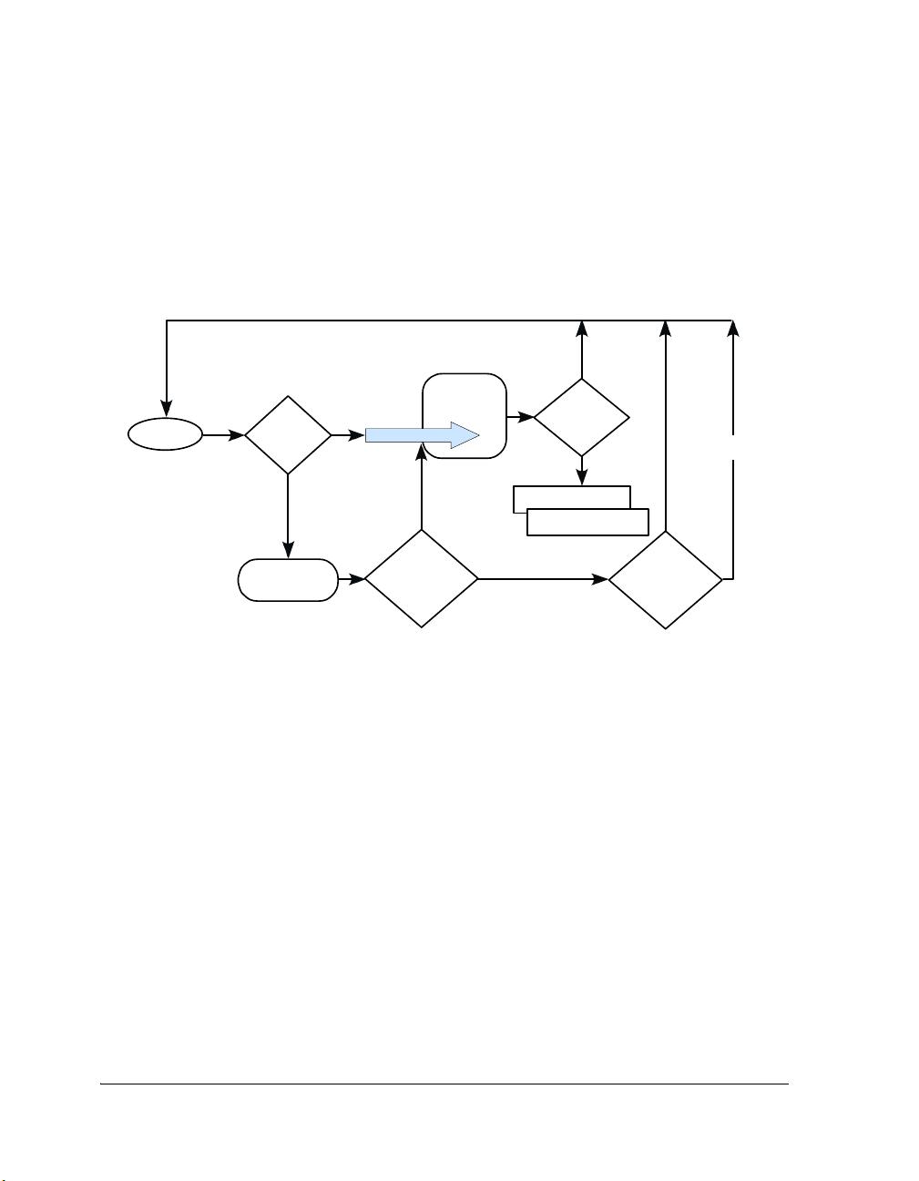
Signals
Pending on an Event
Like semaphores, threads can pend on an event’s condition becoming
TRUE
with a timeout. Figure 3-12 illustrates the process of pending on an event.
Thread 1continues execution
Yes
Thread 1
PendEvent()
Does
Event evaluate
as T RUE?
No
Thread 1 blocks until
Eventis TRUE
Yes
Ready Queue
Order threads
by pr iority, then
All pending threads
No
Is there
a timeout beforethe
Event became
available?
FIFO
1). Invoke Scheduler
Yes
Is
Thread 1
of the
highest
priority?
No
1). Invoke Scheduler
2). Switch outThread 1
2). Switch out Thread 1
Thread 1'serror
function is called
Yes
Is
kNoTimeoutError
set?
No
Figure 3-12. Pending on an Event
A thread calls PendEvent() and specifies the timeout. If the event becomes
TRUE before the timeout is reached, the thread (and all other threads pend-
ing on the event) is moved to the ready queue. Calling PendEvent() with a
timeout of zero means that the thread is willing to wait indefinitely.
Setting or Clearing of Event Bits
Changing the status of the event bits can be accomplished in both the
interrupt domain and the thread domain. Each domain results in slightly
different results.
From the Thread Domain. Figure 3-13 illustrates the process of setting or
clearing of an event bit from the thread domain.
3-42 VisualDSP++ 3.5 Kernel (VDK) User’s Guide
for 16-bit Processors
Page 87
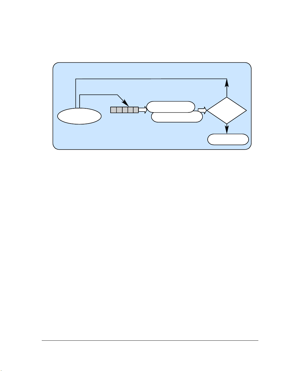
Using VDK
Thread Domain/Scheduled Region
Thread 1 continues execution
SetEventBit()
ClearEventBit()
Thread 1
1). Invoke Scheduler
2). Recalculatedependent bits
Switch out Thread 1
Yes
Is
Thread 1 of
the highest
priority?
No
Figure 3-13. Thread Domain: Setting or Clearing an Event Bit
A thread can set an event bit by calling SetEventBit() and clear it by calling ClearEventBit(). Calling either from within a scheduled region
recalculates all events that depend on the event bit and can result in a
higher priority thread being context switched in.
From the Interrupt Domain. Figure 3-14 on page 3-44 illustrates the pro-
cess of setting or clearing of an event bit from the interrupt domain.
An Interrupt Service Routine can call VDK_ISR_SET_EVENTBIT_()
and VDK_ISR_CLEAR_EVENTBIT_() to change an event bit values
and, possibly, free a new thread to run. Calling these macros does not
result in a recalculation of the events, but the low priority software interrupt is set and the scheduler entered. If the interrupted thread is in a
scheduled region, an event recalculation takes place, and can cause a
higher priority thread to be context switched in. If an ISR sets or clears
VisualDSP++ 3.5 Kernel (VDK) User’s Guide 3-43
for 16-bit Processors
Page 88
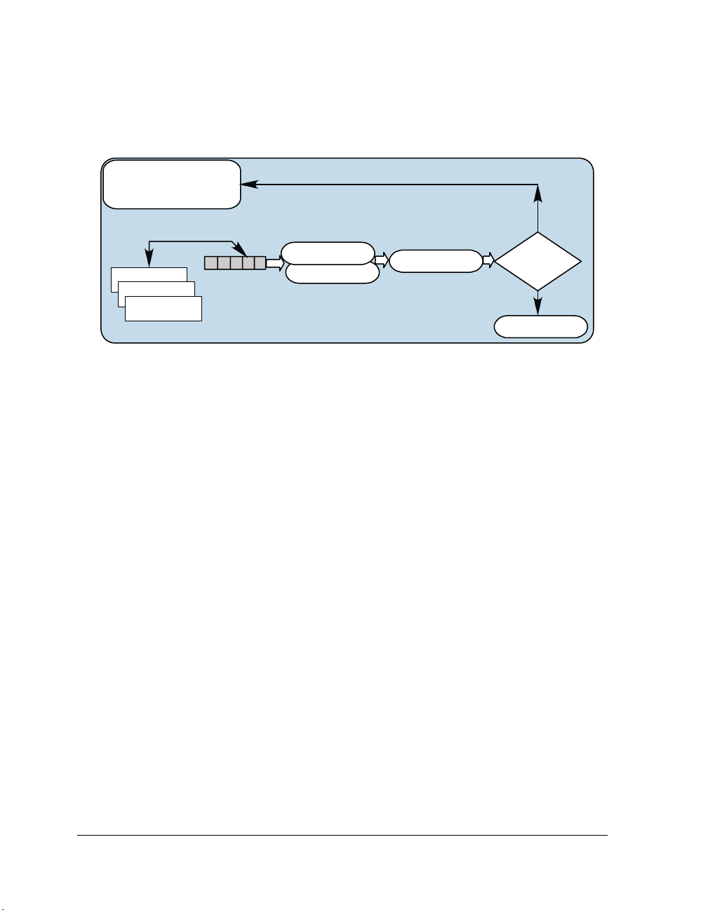
Signals
Thread Domain
VDK_ISR_SET_EVENT BIT _ ()
VDK_ISR_CLEAR_EVENTBIT _ ()
ISR 1
ISR 2
ISR 3
RTI returns to the interrupted thread
1). SetReschedule ISR
2).Invoke Scheduler
Interrupt Domain/Scheduled Region
Recalculate dependent bits
Yes
Is the
interrupted
thread
of the highest
priority?
No
Switch out the
interrupted thread
Figure 3-14. Interrupt Domain: Setting or Clearing an Event Bit
multiple event bits, the calls do not need to be protected with an unscheduled region (since there is no thread scheduling in the interrupt domain);
for example:
/* The following two ISR calls do not need to be protected: */
VDK_ISR_SET_EVENTBIT_(kEventBit1);
VDK_ISR_SET_EVENTBIT_(kEventBit2);
Loading New Event Data into an Event
From the thread scheduling domain, a thread can get the
VDK_EventData
associated with an event with the GetEventData() API. Additionally, a
thread can change the VDK_EventData with the LoadEvent() API. A call to
LoadEvent() causes a recalculation of the event’s value. If a higher priority
thread becomes ready because of the call, it starts running if the scheduler
is enabled.
3-44 VisualDSP++ 3.5 Kernel (VDK) User’s Guide
for 16-bit Processors
Page 89

Using VDK
Device Flags
Because of the special nature of device drivers, most require synchronization methods that are similar to those provided by events and semaphores,
but with different operation. Device flags are created to satisfy the specific
circumstances device drivers might require. Much of their behavior cannot
be fully explained without an introduction to device drivers, which are
covered extensively in“Device Drivers” on page 3-51.
Behavior of Device Flags
Like events and semaphores, a thread can pend on a device flag, but unlike
semaphores and events, a device flag is always FALSE. A thread pending on
a device flag immediately blocks. When a device flag is posted, all threads
pending on it are moved to the ready queue.
Device flags are used to communicate to any number of threads that a
device has entered a particular state. For example, assume that multiple
threads are waiting for a new data buffer to become available from an A/D
converter device. While neither a semaphore nor an event can correctly
represent this state, a device flag’s behavior can encapsulate this system
state.
Thread’s Interaction With Device Flags
A thread accesses a device flag through two APIs: PendDeviceFlag() and
PostDeviceFlag(). Unlike most APIs that can cause a thread to block,
PendDeviceFlag() must be called from within a critical region.
PendDeviceFlag() is set up this way because of the nature of device driv-
ers. See section “Device Drivers” on page 3-51 for a more information
about device flags and device drivers.
VisualDSP++ 3.5 Kernel (VDK) User’s Guide 3-45
for 16-bit Processors
Page 90

Interrupt Service Routines
Interrupt Service Routines
Unlike the Analog Devices standard C implementation of interrupts
(using signal.h), all VDK interrupts are written in assembly. The VDK
encourages users to write interrupts in assembly by giving hand optimized
macros to communicate between the interrupt domain and the thread
domain. All calculations should take place in the thread domain, and
interrupts should be short routines that post semaphores, change event bit
values, activate device drivers, and drop tags in the history buffer.
Enabling and Disabling Interrupts
Each processor architecture has a slightly different mechanism for masking
and unmasking interrupts. Some architectures require that the state of the
interrupt mask be saved to memory before servicing an interrupt or an
exception, and the mask be manually restored before returning. Since the
kernel installs interrupts (and exception handlers on some architectures),
directly writing to the interrupt mask register may produce unintended
results. Therefore, VDK provides a simple and platform independent API
to simplify access to the interrupt mask.
A call to GetInterruptMask() returns the actual value of the interrupt
mask, even if it has been saved temporarily by the kernel in private storage. Likewise, SetInterruptMaskBits() and ClearInterruptMaskBits() set
and clear bits in the interrupt mask in a robust and safe manner. Interrupt
levels with their corresponding bits set in the interrupt mask are enabled
when interrupts are globally enabled. See the Hardware Reference manual
for your target processor for more information about the interrupt mask.
VDK also presents a standard way of turning interrupts on and off globally. Like unscheduled regions (in which the scheduler is disabled) the
VDK supports critical regions where interrupts are disabled. A call to
PushCriticalRegion() disables interrupts, and a call to PopCriticalRegion() reenables interrupts. These API calls implement a stack style
3-46 VisualDSP++ 3.5 Kernel (VDK) User’s Guide
for 16-bit Processors
Page 91

Using VDK
interface, as described in “Protected Regions” on page 1-7. Users are discouraged from turning interrupts off for long sections of code since this
increases interrupt latency.
Interrupt Architecture
Interrupt handling can be set up in two ways: support C functions and
install them as handlers, or support small assembly ISRs that set flags that
are handled in threads or device drivers (which are written in a high level
language). Analog Devices standard C model for interrupts uses signal.h
to install and remove signal (interrupt) handlers that can be written in C.
The problem with this method is that the interrupt space requires a C
run-time context, and any time an interrupt occurs, the system must perform a complete context save/restore.
VDK’s interrupt architecture does not support the signal.h strategy for
handling interrupts. VDK interrupts should be written in assembly, and
their body should set some signal (semaphore, event bit or device flag)
that communicates back to the thread or device driver domain. This architecture reduces the number of context saves/restores required, decreases
interrupt latency, and still keeps as much code as possible in a high-level
language.
The lightweight nature of ISRs also encourages the use of interrupt nesting to further reduce latency. VDK enables interrupt nesting by default on
processors that support it.
Vector Table
VDK installs a common header in every entry in the interrupt table. The
header disables interrupts and jumps to the interrupt handler. Interrupts
are disabled in the header so that you can depend on having access to global data structures at the beginning of their handler. You must remember
to reenable interrupts before executing an RTI.
VisualDSP++ 3.5 Kernel (VDK) User’s Guide 3-47
for 16-bit Processors
Page 92

Interrupt Service Routines
The VDK reserves (at least) two interrupts: the timer interrupt and the
lowest priority software interrupt. For a discussion about the timer interrupt, see “Timer ISR” on page 3-50. For information about the lowest
priority software interrupt, see “Reschedule ISR” on page 3-50. For information on any additional interrupts reserved by the VDK for particular
processors, see “Processor-Specific Notes” on page A-1.
Global Data
Often ISRs need to communicate data back and forth to the thread
domain besides semaphores, event bits, and device driver activations. ISRs
can use global variables to get data to the thread domain, but you must
remember to wrap any access to or from that global data in a critical
region and to declare the variable as
volatile (in C/C++). For example,
consider the following:
/* MY_ISR.asm */
.EXTERN _my_global_integer;
<REG> = data;
DM(_my_global_integer) = <REG>;
/* finish up the ISR, enable interrupts, and RTI. */
And in the thread domain:
/* My_C_Thread.c */
volatile int my_global_integer;
/* Access the global ISR data */
VDK_PushCriticalRegion();
if (my_global_integer == 2)
my_global_integer = 3;
VDK_PopCriticalRegion();
3-48 VisualDSP++ 3.5 Kernel (VDK) User’s Guide
for 16-bit Processors
Page 93

Using VDK
Communication with the Thread Domain
The VDK supplies a set of macros that can be used to communicate system state to the thread domain. Since these macros are called from the
interrupt domain, they make no assumptions about processor state, available registers, or parameters. In other words, the ISR macros can be called
without consideration of saving state or having processor state trampled
during a call.
Take for example, the following three equivalent
VDK_ISR_POST_SEMAPHORE_() calls:
.VAR/DATA semaphore_id;
/* Pass the value directly */
VDK_ISR_POST_SEMAPHORE_(kSemaphore1);
/* Pass the value in a register */
<REG> = kSemaphore1;
VDK_ISR_POST_SEMAPHORE_(<REG>);
/* <REG> was not trampled */
/* Post the semaphore one last time using a DM
DM(semaphore_id) = <REG>;
VDK_ISR_POST_SEMAPHORE_(DM(semaphore_id));
*/
Additionally, no condition codes are affected by the ISR macros, no
assumptions are made about having space on any hardware stacks (e.g. PC
or status), and all VDK internal data structures are maintained.
Most ISR macros raise the low priority software interrupt if thread
domain scheduling is required after all other interrupts are serviced. For a
discussion of the low priority software interrupt, see section “Reschedule
ISR” on page 3-50. Refer to “Processor-Specific Notes” on page A-1 for
additional information about ISR APIs.
VisualDSP++ 3.5 Kernel (VDK) User’s Guide 3-49
for 16-bit Processors
Page 94

Interrupt Service Routines
Within the interrupt domain, every effort should be made to enable interrupt nesting. Nesting is always disabled when an ISR begins. However,
leaving it disabled is analogous to staying in an unscheduled region in the
thread domain; other ISRs are prevented from executing, even if they have
higher priority. Allowing nested interrupts potentially lowers interrupt
latency for high priority interrupts.
Timer ISR
The VDK reserves a timer interrupt. The timer is used to calculate
round-robin times, sleeping threads’ time to keep sleeping, and periodic
semaphores. One VDK tick is defined as the time between timer interrupts and is the finest resolution measure of time in the kernel. The timer
interrupt can cause a low priority software interrupt (see “Reschedule ISR”
on page 3-50). In VisualDSP++ 3.5 it is possible to change the interrupt
used for the VDK timer interrupt from the default (see online Help for
further information).
Reschedule ISR
The VDK designates the lowest priority interrupt that is not tied to a
hardware device as the reschedule ISR. This ISR handles housekeeping
when an interrupt causes a system state change that can result in a new
high priority thread becoming ready. If a new thread is ready and the system is in a scheduled region, the software ISR saves off the context of the
current thread and switches to the new thread. If an interrupt has activated a device driver, the low priority software interrupt calls the dispatch
function for the device driver. For more information, see “Dispatch Func-
tion” on page 3-56.
On systems where the lowest priority non-hardware-tied interrupt is not
the lowest priority interrupt, all lower priority interrupts must run with
interrupts turned off for their entire duration. Failure to do so may result
in undefined behavior.
3-50 VisualDSP++ 3.5 Kernel (VDK) User’s Guide
for 16-bit Processors
Page 95

Using VDK
I/O Interface
The I/O interface provides the mechanism for creating an interface
between the external environment and VDK applications.
In VisualDSP++ 3.5, only device driver objects can be used to construct
the I/O interface.
I/O Templates
I/O templates are analogous to thread types. I/O templates are used to
instantiate I/O objects. In VisualDSP++ 3.5, the only types of I/O templates available, and therefore the only classes of I/O objects, are for device
drivers. In order to create an instance of a device driver, a boot I/O object
must be added to the VDK project using the device driver template. In
order to distinguish between different instances of the same I/O template
an 'initializer' value can be passed to an I/O object (see online Help for
further information).
Device Drivers
The role of a device driver is to abstract the details of the hardware implementation from the software designer. For example, a software engineer
designing a finite impulse response (FIR) filter does not need to understand the intricacies of the converters, and is able to concentrate on the
FIR algorithm. The software can then be reused on different platforms,
where the hardware interface differs.
VisualDSP++ 3.5 Kernel (VDK) User’s Guide 3-51
for 16-bit Processors
Page 96

I/O Interface
The Communication Manager controls device drivers in the VDK. Using
the Communication Manager APIs, you can maintain the abstraction layers between device drivers, interrupt service routines, and executing
threads. This section details how the Communication Manager is
organized.
L
Execution
Device drivers and interrupt service routines are tied very closely together.
Typically, DSP developers prefer to keep as much time critical code in
assembly as possible. The Communication Manager is designed such that
you can keep interrupt routines in assembly (the time critical pieces), and
interface and resource management for the device in a high level language
without sacrificing speed. The Communication Manager attempts to keep
the number of context switches to a minimum, to execute management
code at reasonable times, and to preserve the order of priorities of running
threads when a thread uses a device. However, you need to thoroughly
understand the architecture of the Communication Manager to write your
device driver.
There is only one interface to a device driver—through a dispatch function. The dispatch function is called when the device is initialized, when a
thread uses a device (open/close, read/write, control), or when an interrupt service routine transfers data to or from the device. The dispatch
function handles the request and returns. Device drivers should not block
(pend) when servicing an initialize request or a request for more data by
an interrupt service routine. However, a device driver can block when servicing a thread request and the relevant resource is not ready or available.
In VisualDSP++ 3.5, device drivers are a part of the I/O interface.
Device drivers are added to a VDK project as I/O objects. VisualDSP++ 2.0 device drivers are not compatible with VisualDSP++
3.5 device drivers. See “Migrating Device Drivers” on page B-1 for
a description of how to convert existing VisualDSP++ 2.0 device
drivers for use in VisualDSP++ 3.5 projects.
3-52 VisualDSP++ 3.5 Kernel (VDK) User’s Guide
for 16-bit Processors
Page 97

Using VDK
Device driver initialization and ISR requests are handled within critical
regions enforced by the kernel, so their execution does not have to be
reentrant, but a thread level request must protect global variables within
critical or unscheduled regions.
Parallel Scheduling Domains
This section focuses on a unique role of device drivers in the VDK architecture. Understanding device drivers requires some understanding of the
time and method by which device driver code is invoked. VDK applications may be factored into two domains, referred to as the thread domain
and the ISR domain (see Figure 3-15). This distinction is not an arbitrary
or unnecessary abstraction. The hardware architecture of the processor as
well as the software architecture of the kernel reinforces this notion. You
should consider this distinction when you are designing your application
and apportioning your code.
Threads are scheduled based on their priority and the order in which they
are placed in the ready queue. The scheduling portion of the kernel is
responsible for selecting the thread to run. However, the scheduler does
not have complete control over the processor. It may be preempted by a
parallel and higher priority scheduler: the interrupt and exception hardware. While interrupts or exceptions are being serviced, thread priorities
are temporarily moot. The position of threads in the ready queue becomes
significant again only when the hardware relinquishes control back to the
software based scheduler.
Each of the domains has strengths and weaknesses that dictate the type of
code suitable to be executed in that environment. The scheduler in the
thread domain is invoked when threads are moved to or from the ready
queue. Threads each have their own stack and may be written in a high
level language. Threads always execute in “supervisor” or “kernel mode”
(if the processor makes this distinction). Threads implement algorithms
and are allotted processor time based on the completion of higher priority
activity.
VisualDSP++ 3.5 Kernel (VDK) User’s Guide 3-53
for 16-bit Processors
Page 98
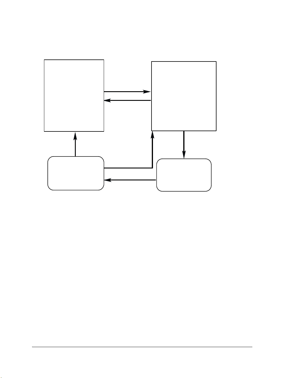
I/O Interface
Thread Domain ISR Domain
software/kernel
scheduling is
based on
thread priority
Thread
selected
Scheduler
Interru p t
All ISRs
complete and
no change
of state
All ISRs
complete and
state changed
hardware
scheduling is
based on
interrupt priority
All ISRs complete
and DD activated
Device
Drivers
Device Flags
Figure 3-15. Parallel Scheduling Domains
In contrast, scheduling in the interrupt domain has the highest system
wide priority. Any “ready” ISR takes precedence over any ready thread
(outside critical regions), and this form of scheduling is implemented in
hardware. ISRs are always written in assembly and must manually restore
any registers they use. ISRs execute in “supervisor” or “kernel mode” (if
the processor makes this distinction). ISRs respond to asynchronous
peripherals at the lowest level only. The routine should perform only
activities that are so time critical that data would be lost if the code were
not executed as soon as possible. All other activity should occur under the
control of the kernel's scheduler based on priority.
Transferring from the thread domain to the interrupt domain is simple
and automatic, but returning to the thread domain can be much more
laborious. If the ready queue is not changed while in the interrupt
domain, then the scheduler need not run when it regains control of the
3-54 VisualDSP++ 3.5 Kernel (VDK) User’s Guide
for 16-bit Processors
Page 99

Using VDK
system. The interrupted thread resumes execution immediately. If the
ready queue has changed, the scheduler must further determine whether
the highest priority thread has changed. If it has changed, the scheduler
must initiate a context switch.
Device drivers fill the gap between the two scheduling domains. They are
neither thread code nor ISR code, and they are not directly scheduled by
either the kernel or the interrupt controller. Device drivers are implemented as C++ objects and run on the stack of the currently running
thread. However, they are not “owned” by any thread, and may be used by
many threads concurrently.
Using Device Drivers
From the point of view of a thread, there are five functional interfaces to
device drivers: OpenDevice(), CloseDevice(), SyncRead(), SyncWrite(),
and DeviceIOCtl(). The names of the APIs are self explanatory since
threads mostly treat device drivers as black boxes. Figure 3-16 illustrates
the device drivers’ interface. A thread uses a device by opening it, reading
and/or writing to it, and closing it. The DeviceIOCtl() function is used
for sending device-specific control information messages. Each API is a
standard C/C++ function call that runs on the stack of the calling thread
and returns when the function completes. However, when the device
driver does not have a needed resource, one of these functions may cause
the thread to be removed from the ready queue and block on a signal, similar to a semaphore or an event, called a device flag.
Interrupt service routines have only one API call relating to device drivers:
VDK_ISR_ACTIVATE_DEVICE_(). This macro is not a function call,
and program flow does not transfer from the ISR to the device driver and
back. Rather, the macro sets a flag indicating that the device driver's “activate” routine should execute after all interrupts have been serviced.
The remaining two API functions, PendDeviceFlag() and PostDevice-
Flag(), can be called only from within the device driver itself. For example,
a call from a thread to SyncRead() might cause the device driver to call
VisualDSP++ 3.5 Kernel (VDK) User’s Guide 3-55
for 16-bit Processors
Page 100

I/O Interface
MyThread::Run()
(interrupt)
Open Device( )
CloseDevice()
SyncRead ()
SyncWri te()
DeviceIOCtl()
(return)
ISR
V DK_ ISR _ACTI VA TE_ DEVIC E_
Device Driver
PendDeviceFlag()
PostDeviceFlag()
Device Flag
Figure 3-16. Device Driver APIs
PendDeviceFlag() if there is no data currently available. This would cause
the thread to block until the device flag is posted by another code fragment within the device driver that is providing the data.
As another example, when an interrupt occurs because an incoming data
buffer is full, the ISR might move a pointer so that the device begins filling an empty buffer before calling VDK_ISR_ACTIVATE_DEVICE_().
The device driver's activate routine may respond by posting a device flag
and moving a thread to the ready queue so that it can be scheduled to process the new data.
Dispatch Function
The dispatch function is the core of any device driver. It takes two parameters and returns a
void* (the return value depends on the input values). A
dispatch function declaration for a device driver is as follows:
3-56 VisualDSP++ 3.5 Kernel (VDK) User’s Guide
for 16-bit Processors
 Loading...