

Page 1

W 3.5
Linker and Utilities Manual
for 16-Bit Processors
Analog Devices, Inc.
One Technology Way
Norwood, Mass. 02062-9106
Revision 1.0, October 2003
Part Number
82-000035-07
a
Page 2

Copyright Information
© 2003 Analog Devices, Inc., ALL RIGHTS RESERVED. This document may not be reproduced in any form without prior, express written
consent from Analog Devices, Inc.
Printed in the USA.
Disclaimer
Analog Devices, Inc. reserves the right to change this product without
prior notice. Information furnished by Analog Devices is believed to be
accurate and reliable. However, no responsibility is assumed by Analog
Devices for its use; nor for any infringement of patents or other rights of
third parties which may result from its use. No license is granted by implication or otherwise under the patent rights of Analog Devices, Inc.
Trademark and Service Mark Notice
The Analog Devices logo, VisualDSP++, the VisualDSP++ logo, Blackfin,
and the Blackfin logo are registered trademarks of Analog Devices, Inc.
All other brand and product names are trademarks or service marks of
their respective owners.
Page 3

CONTENTS
PREFACE
Purpose of This Manual .................................................................. xv
Intended Audience ......................................................................... xvi
Manual Contents ........................................................................... xvi
What’s New in This Manual .......................................................... xvii
Technical or Customer Support .................................................... xviii
Supported Processors ...................................................................... xix
Product Information ....................................................................... xx
MyAnalog.com .......................................................................... xx
DSP Product Information .......................................................... xx
Related Documents .................................................................. xxi
Online Technical Documentation ............................................ xxii
From VisualDSP++ ............................................................. xxii
From Windows ................................................................. xxiii
From the Web ................................................................... xxiii
Printed Manuals ..................................................................... xxiv
VisualDSP++ Documentation Set ....................................... xxiv
Hardware Manuals ............................................................. xxiv
Data Sheets ........................................................................ xxiv
VisualDSP++ 3.5 Linker and Utilities Manual iii
for 16-Bit Processors
Page 4

CONTENTS
Contacting DSP Publications .................................................. xxv
Notation Conventions .................................................................. xxv
INTRODUCTION
Software Development Flow ......................................................... 1-2
Compiling and Assembling ........................................................... 1-3
Inputs – C/C++ and Assembly Sources .................................... 1-3
Input Section Directives in Assembly Code .............................. 1-4
Input Section Directives in C/C++ Source Files ........................ 1-4
Linking ........................................................................................ 1-6
Linker and Assembler Preprocessor .......................................... 1-7
Loading and Splitting ................................................................... 1-8
LINKER
Linker Operation .......................................................................... 2-2
Directing Linker Operation ..................................................... 2-3
Linking Process Rules .............................................................. 2-4
Linker Description File — Overview ....................................... 2-5
Linking Environment ................................................................... 2-6
Project Builds ......................................................................... 2-6
Expert Linker .......................................................................... 2-9
Linker Warning and Error Messages ...................................... 2-10
Link Target Description .............................................................. 2-11
Representing Memory Architecture ........................................ 2-11
ADSP-BF535 Processor Memory Architecture Overview .... 2-12
iv VisualDSP++ 3.5 Linker and Utilities Manual
for 16-Bit Processors
Page 5

CONTENTS
ADSP-218x DSP Core Architecture Overview ................... 2-15
ADSP-219x DSP Architecture Overview ............................ 2-17
Specifying the Memory Map .................................................. 2-18
Memory Usage .................................................................. 2-18
Memory Characteristics ..................................................... 2-20
Linker MEMORY{} Command in .LDF File ...................... 2-24
Placing Code on the Target .................................................... 2-26
Passing Arguments for Simulation or Emulation: Blackfin Processors ONLY
2-29
Linker Command-Line Reference ................................................ 2-30
Linker Command-Line Syntax ............................................... 2-30
Command-Line Object Files ............................................. 2-31
Command-Line File Names ............................................... 2-32
Object File Types .............................................................. 2-34
Linker Command-Line Switches ............................................ 2-34
Linker Switch Summary .................................................... 2-36
@filename ......................................................................... 2-38
-Dprocessor ...................................................................... 2-38
-L path ............................................................................. 2-39
-M .................................................................................... 2-39
-MM ................................................................................ 2-39
-Map filename .................................................................. 2-39
-MDmacro[=def] .............................................................. 2-39
-Ovcse .............................................................................. 2-40
-S ..................................................................................... 2-40
VisualDSP++ 3.5 Linker and Utilities Manual v
for 16-Bit Processors
Page 6

CONTENTS
-T filename ...................................................................... 2-40
-Wwarn [number] ............................................................ 2-40
-e ..................................................................................... 2-41
-es sectionName ............................................................... 2-41
-ev ................................................................................... 2-41
-flags-meminit -opt1[,-opt2... .......................................... 2-41
-flags-pp -opt1[,-opt2...] .................................................. 2-42
-h[elp] .............................................................................. 2-42
-i|I directory ..................................................................... 2-42
-ip .................................................................................... 2-42
-jcs2l ................................................................................ 2-43
-jcs2l+ .............................................................................. 2-44
-keep symbolName ........................................................... 2-44
-meminit .......................................................................... 2-44
-o filename ....................................................................... 2-44
-od directory .................................................................... 2-45
-pp ................................................................................... 2-45
-proc processor ................................................................. 2-45
-s ..................................................................................... 2-46
-save-temps ...................................................................... 2-46
-si-revision version ............................................................ 2-46
-sp ................................................................................... 2-48
-t ..................................................................................... 2-48
-v[erbose] ......................................................................... 2-48
vi VisualDSP++ 3.5 Linker and Utilities Manual
for 16-Bit Processors
Page 7

CONTENTS
-version ............................................................................ 2-48
-warnonce ......................................................................... 2-48
-xref filename .................................................................... 2-49
LINKER DESCRIPTION FILE
LDF File Overview ....................................................................... 3-3
Example 1 – Basic .LDF File for Blackfin Processors ................. 3-4
Example 2 - Basic .LDF File for ADSP-218/9x DSPs ................ 3-6
Notes on Basic .LDF File Examples .......................................... 3-7
LDF Structure ............................................................................ 3-11
Command Scoping ................................................................ 3-12
LDF Expressions ......................................................................... 3-13
LDF Keywords, Commands, and Operators ................................. 3-14
Miscellaneous LDF Keywords ................................................ 3-15
LDF Operators ........................................................................... 3-16
ABSOLUTE() Operator ........................................................ 3-16
ADDR() Operator ................................................................. 3-17
DEFINED() Operator ........................................................... 3-18
MEMORY_SIZEOF() Operator ............................................ 3-18
SIZEOF() Operator ............................................................... 3-19
Location Counter (.) .............................................................. 3-19
LDF Macros ............................................................................... 3-20
Built-In LDF Macros ............................................................. 3-21
User-Declared Macros ........................................................... 3-22
LDF Macros and Command-Line Interaction ......................... 3-22
VisualDSP++ 3.5 Linker and Utilities Manual vii
for 16-Bit Processors
Page 8

CONTENTS
LDF Commands ........................................................................ 3-23
ALIGN() .............................................................................. 3-24
ARCHITECTURE() ............................................................. 3-24
ELIMINATE() ...................................................................... 3-25
ELIMINATE_SECTIONS() ................................................. 3-26
INCLUDE() ......................................................................... 3-26
INPUT_SECTION_ALIGN() .............................................. 3-26
KEEP() ................................................................................. 3-27
LINK_AGAINST() ............................................................... 3-28
MAP() .................................................................................. 3-29
MEMORY{} ......................................................................... 3-29
Segment Declarations ....................................................... 3-30
MPMEMORY{} .................................................................... 3-32
OVERLAY_GROUP{} .......................................................... 3-33
PACKING() ......................................................................... 3-33
Packing in ADSP-218x and ADSP-219x DSPs ................. 3-34
Efficient Packing ........................................................... 3-35
Inefficient Packing: Null Bytes ...................................... 3-36
Overlay Packing Formats .............................................. 3-37
Trivial Packing: No Reordering ..................................... 3-37
PAGE_INPUT() ................................................................... 3-37
PAGE_OUTPUT() ............................................................... 3-38
PLIT{} .................................................................................. 3-38
PROCESSOR{} .................................................................... 3-39
viii VisualDSP++ 3.5 Linker and Utilities Manual
for 16-Bit Processors
Page 9

CONTENTS
RESOLVE() .......................................................................... 3-40
SEARCH_DIR() ................................................................... 3-41
SECTIONS{} ........................................................................ 3-42
INPUT_SECTIONS() ...................................................... 3-45
expression ......................................................................... 3-45
FILL(hex number) ............................................................ 3-46
PLIT{plit_commands} ...................................................... 3-46
OVERLAY_INPUT{overlay_commands} ........................... 3-46
SHARED_MEMORY{} ......................................................... 3-48
EXPERT LINKER
Expert Linker Overview ................................................................ 4-2
Launching the Create LDF Wizard ................................................ 4-4
Step 1: Specifying Project Information ..................................... 4-5
Step 2: Specifying System Information ..................................... 4-6
Step 3: Completing the LDF Wizard ........................................ 4-9
Expert Linker Window Overview ................................................ 4-10
Input Sections Pane ..................................................................... 4-12
Input Sections Menu ............................................................. 4-12
Mapping an Input Section to an Output Section .................... 4-14
Viewing Icons and Colors ...................................................... 4-14
Sorting Objects ..................................................................... 4-17
Memory Map Pane ...................................................................... 4-18
Context Menu ....................................................................... 4-20
Tree View Memory Map Representation ................................. 4-22
VisualDSP++ 3.5 Linker and Utilities Manual ix
for 16-Bit Processors
Page 10

CONTENTS
Graphical View Memory Map Representation ........................ 4-23
Specifying Pre- and Post-Link Memory Map View ................. 4-27
Zooming In and Out on the Memory Map ............................ 4-28
Inserting a Gap into a Memory Segment ................................ 4-31
Working With Overlays ........................................................ 4-33
Viewing Section Contents ..................................................... 4-35
Viewing Symbols .................................................................. 4-39
Profiling Object Sections ....................................................... 4-40
Adding Shared Memory Segments and Linking Object Files ... 4-45
Managing Object Properties ........................................................ 4-50
Managing Global Properties .................................................. 4-51
Managing Processor Properties .............................................. 4-52
Managing PLIT Properties for Overlays ................................. 4-54
Managing Elimination Properties .......................................... 4-55
Managing Symbols Properties ................................................ 4-57
Managing Memory Segment Properties .................................. 4-61
Managing Output Section Properties ..................................... 4-62
Managing Packing Properties ................................................. 4-64
Managing Alignment and Fill Properties ................................ 4-65
Managing Overlay Properties ................................................. 4-67
Managing Stack and Heap in Processor Memory .................... 4-69
MEMORY OVERLAYS AND ADVANCED LDF
COMMANDS
Overview ...................................................................................... 5-2
x VisualDSP++ 3.5 Linker and Utilities Manual
for 16-Bit Processors
Page 11

CONTENTS
Memory Management Using Overlays ........................................... 5-4
Introduction to Memory Overlays ............................................ 5-5
Overlay Managers .................................................................... 5-7
Breakpoints on Overlays ...................................................... 5-7
Memory Overlay Support ........................................................ 5-8
Example – Managing Two Overlays ....................................... 5-12
Linker-Generated Constants .................................................. 5-15
Overlay Word Sizes ................................................................ 5-15
Storing Overlay ID ................................................................ 5-16
Overlay Manager Function Summary ..................................... 5-17
Reducing Overlay Manager Overhead .................................... 5-17
Using PLIT{} and Overlay Manager ....................................... 5-22
Inter-Overlay Calls ............................................................ 5-24
Inter-Processor Calls ......................................................... 5-24
Advanced LDF Commands ......................................................... 5-27
MPMEMORY{} .................................................................... 5-28
OVERLAY_GROUP{} ........................................................... 5-29
Ungrouped Overlay Execution ........................................... 5-31
Grouped Overlay Execution .............................................. 5-33
PLIT{} .................................................................................. 5-34
PLIT Syntax ..................................................................... 5-34
Command Evaluation and Setup ................................... 5-35
Allocating Space for PLITs ................................................ 5-36
PLIT Example .................................................................. 5-37
VisualDSP++ 3.5 Linker and Utilities Manual xi
for 16-Bit Processors
Page 12

CONTENTS
PLIT – Summary .............................................................. 5-37
SHARED_MEMORY{} ........................................................ 5-38
ARCHIVER
Archiver Guide ............................................................................. 6-2
Creating a Library From VisualDSP++ ..................................... 6-3
Making Archived Functions Usable ......................................... 6-3
Writing Archive Routines: Creating Entry Points ................. 6-4
Accessing Archived Functions From Your Code ................... 6-5
Archiver File Searches ......................................................... 6-6
Tagging an Archive with Version Information ...................... 6-6
Basic Version Information ............................................... 6-6
User-Defined Version Information .................................. 6-7
Printing Version Information .......................................... 6-8
Removing Version Information from an Archive .............. 6-9
Checking Version Number .............................................. 6-9
Adding Text to Version Information .............................. 6-10
Archiver Command-Line Reference ............................................. 6-11
elfar Command Syntax .......................................................... 6-11
Archiver Parameters and Switches .......................................... 6-12
Command-Line Constraints .................................................. 6-14
Archiver Symbol Name Encryption ....................................... 6-15
FILE FORMATS
Source Files .................................................................................. A-2
xii VisualDSP++ 3.5 Linker and Utilities Manual
for 16-Bit Processors
Page 13

C/C++ Source Files ................................................................. A-2
Assembly Source Files (.ASM) ................................................. A-3
Assembly Initialization Data Files (.DAT) ............................... A-3
Header Files (.H) .................................................................... A-4
Linker Description Files (.LDF) .............................................. A-4
Linker Command-Line Files (.TXT) ....................................... A-5
Build Files ................................................................................... A-5
Assembler Object Files (.DOJ) ................................................ A-5
Library Files (.DLB) ............................................................... A-6
Linker Output Files (.DXE, .SM, and .OVL) .......................... A-6
Memory Map Files (.XML) ..................................................... A-6
Loader Output Files in Intel Hex-32 Format (.LDR) ............... A-6
Splitter Output Files in ASCII Format (.LDR) ........................ A-8
Debugger Files ............................................................................. A-9
Format References ...................................................................... A-10
UTILITIES
elfdump – ELF File Dumper ........................................................ B-1
Disassembling a Library Member ............................................ B-3
Dumping Overlay Library Files ............................................... B-4
LDF PROGRAMMING EXAMPLES FOR BLACKFIN
PROCESSORS
Linking for a Single-Processor System ........................................... C-2
Linking Large Uninitialized or Zero-initialized Variables ............... C-4
VisualDSP++ 3.5 Linker and Utilities Manual xiii
for 16-Bit Processors
Page 14

Linking for Assembly Source File .................................................. C-6
Linking for C Source File – Example 1 .......................................... C-8
Linking for Complex C Source File – Example 2 ......................... C-11
Linking for Overlay Memory ...................................................... C-17
LDF PROGRAMMING EXAMPLES FOR ADSP-21XX DSPS
Linking for a Single-Processor ADSP-219x System ....................... D-3
Linking Large Uninitialized or Zero-initialized Variables ............... D-5
Linking an Assembly Source File .................................................. D-7
Linking a Simple C-Based Source File .......................................... D-9
Linking Overlay Memory for an ADSP-2191 System .................. D-16
Linking an ADSP-219x MP System With Shared Memory .......... D-19
Overlays Used With ADSP-218x DSPs ...................................... D-23
INDEX
xiv VisualDSP++ 3.5 Linker and Utilities Manual
for 16-Bit Processors
Page 15

PREFACE
Thank you for purchasing Analog Devices development software for digital signal processors (DSPs).
Purpose of This Manual
The VisualDSP++ 3.5 Linker and Utilities Manual for 16-Bit Processors
contains information about the linker and utilities programs for 16-bit
fixed-point Blackfin® processors and ADSP-21xx DSPs.
The Blackfin processors are 16-bit fixed-point embedded processors that
support a Media Instruction Set Computing (MISC) architecture. This
architecture is the natural merging of RISC, media functions, and digital
signal processing (DSP) characteristics towards delivering signal processing performance in a microprocessor-like environment.
The ADSP-218x and ADSP-219x DSPs are low-cost 16-bit fixed-point
DSPs for use in computing, communications, and consumer applications.
This manual provides information on the linking process and describes
the syntax for the linker’s command language—a scripting language that
the linker reads from the linker description file. The manual leads you
through using the linker, archiver, and loader to produce DSP programs
and provides reference information on the file utility software.
VisualDSP++ 3.5 Linker and Utilities Manual xv
for 16-Bit Processors
Page 16

Intended Audience
Intended Audience
The manual is primarily intended for programmers who are familiar with
Analog Devices embedded processors and DSPs. This manual assumes
that the audience has a working knowledge of the appropriate device
architecture and instruction set. Programmers who are unfamiliar with
Analog Devices DSPs can use this manual but should supplement it with
other texts, such as Hardware Reference and Instruction Set Reference manuals, that describe your target architecture.
Manual Contents
The manual contains:
• Chapter 1, “Introduction”
This chapter provides an overview of the linker and utilities.
• Chapter 2, “Linker”
This chapter describes how to combine object files into reusable
library files to link routines referenced by other object files.
• Chapter 3, “Linker Description File”
This chapter describes how to write an .LDF file to define the
target.
• Chapter 4, “Expert Linker”
This chapter describes Expert Linker, which is an interactive
graphical tool to set up and map DSP memory.
• Chapter 5, “Memory Overlays and Advanced LDF Commands”
This chapter describes how overlays and advanced LDF commands
are used for memory management.
xvi VisualDSP++ 3.5 Linker and Utilities Manual
for 16-Bit Processors
Page 17

Preface
• Chapter 6 “Archiver”
This chapter describes the elfar archiver utility used to combine
object files into library files, which serve as reusable resources for
code development.
•Appendix A, “File Formats”
This appendix lists and describes the file formats that the development tools use as inputs or produce as outputs.
•Appendix B, “Utilities”
This appendix describes the utilities that provide legacy and file
conversion support.
• Appendix C, “LDF Programming Examples for Blackfin
Processors”
This appendix provides code examples of .LDF files used with
Blackfin processors.
• Appendix D, “LDF Programming Examples for ADSP-21xx
DSPs”
This appendix provides code examples of .LDF files used with
ADSP-21xx DSPs.
What’s New in This Manual
This is a new manual that documents support for 16-bit fixed-point
Blackfin processors and ADSP-21xx DSPs.
This manual now combines linker-related information for all ADI 16-bit
fixed-point processors. The manual provides information for Blackfin
processors, ADSP-218x DSPs and ADSP-219x DSPs.
Loader/splitter information is now available in separate Loader manuals
for appropriate target processor families.
Refer to VisualDSP++ 3.5 Product Bulletin for 16-Bit Processors for information on all new and updated features and other release information.
VisualDSP++ 3.5 Linker and Utilities Manual xvii
for 16-Bit Processors
Page 18

Technical or Customer Support
Technical or Customer Support
You can reach DSP Tools Support in the following ways:
• Visit the DSP Development Tools website at
http://www.analog.com/technology/dsp/developmentTools/index.html
• E-mail questions to
dsptools.support@analog.com
• Phone questions to 1-800-ANALOGD
• Contact your ADI local sales office or authorized distributor
• Send questions by mail to:
Analog Devices, Inc.
One Technology Way
P.O. Box 9106
Norwood, MA 02062-9106
USA
xviii VisualDSP++ 3.5 Linker and Utilities Manual
for 16-Bit Processors
Page 19

Preface
Supported Processors
Blackfin Processors
The name “Blackfin” refers to a family of Analog Devices 16-bit,
fixed-point embedded processors. VisualDSP++ currently supports the
following processors:
• ADSP-BF532 (formerly ADSP-21532)
• ADSP-BF535 (formerly ADSP-21535)
• ADSP-BF531
• ADSP-BF533
• ADSP-BF561
• AD6532
• AD90747
The ADSP-BF531 and ADSP-BF533 processors are memory variants of
the ADSP-BF532 processor as well as a dual-core ADSP-BF561 processor.
ADSP-218x and ADSP-219x DSPs
The name “ADSP-21xx” refers to two families of Analog Devices 16-bit,
fixed-point processors. VisualDSP++ currently supports the following
processors:
• ADSP-218x DSPs: ADSP-2181, ADSP-2183,
ADSP-2184/84L/84N, ADSP-2185/85L/85M/85N,
ADSP-2186/86L/86M/86N, ADSP-2187L/87N,
ADSP-2188L/88N, and ADSP-2189M/89N
• ADSP-219x DSPs: ADSP-2191, ADSP-2192-12, ADSP-2195,
ADSP-2196, ADSP-21990, ADSP-21991, and ADSP-21992
VisualDSP++ 3.5 Linker and Utilities Manual xix
for 16-Bit Processors
Page 20

Product Information
Product Information
You can obtain product information from the Analog Devices website,
from the product CD-ROM, or from the printed publications (manuals).
Analog Devices is online at www.analog.com. Our website provides information about a broad range of products—analog integrated circuits,
amplifiers, converters, and digital signal processors.
MyAnalog.com
MyAnalog.com is a free feature of the Analog Devices website that allows
customization of a webpage to display only the latest information on
products you are interested in. You can also choose to receive weekly
e-mail notification containing updates to the webpages that meet your
interests. MyAnalog.com provides access to books, application notes, data
sheets, code examples, and more.
Registration:
Visit www.myanalog.com to sign up. Click Register to use MyAnalog.com.
Registration takes about five minutes and serves as means for you to select
the information you want to receive.
If you are already a registered user, simply log on. Your user name is your
e-mail address.
DSP Product Information
For information on digital signal processors, visit our website at
www.analog.com/dsp, which provides access to technical publications, data
sheets, application notes, product overviews, and product announcements.
You may also obtain additional information about Analog Devices and its
products in any of the following ways.
xx VisualDSP++ 3.5 Linker and Utilities Manual
for 16-Bit Processors
Page 21

Preface
• Email questions or requests for information to
dsp.support@analog.com
• Fax questions or requests for information to
1-781-461-3010 (North America)
089/76 903-557 (Europe)
• Access the Digital Signal Processing Division’s FTP website at
ftp ftp.analog.com or ftp 137.71.23.21
ftp://ftp.analog.com
Related Documents
For information on product related development software, see the following publications:
VisualDSP++ 3.5 Getting Started Guide for 16-Bit Processors
VisualDSP++ 3.5 User’s Guide for 16-Bit Processors
VisualDSP++ 3.5 Assembler and Preprocessor Manual for Blackfin Processors
VisualDSP++ 3.5 C Compiler and Library Manual for Blackfin Processors
VisualDSP++ 3.5 Product Bulletin for 16-Bit Processors
VisualDSP++ 3.5 Assembler and Preprocessor Manual for ADSP-21xx DSPs
VisualDSP++ 3.5 C Compiler and Library Manual for ADSP-218x DSPs
VisualDSP++ 3.5 C/C++ Compiler and Library Manual for ADSP-219x DSPs
VisualDSP++ 3.5 Loader Manual for 16-Bit Processors
VisualDSP++ Kernel (VDK) User’s Guide
VisualDSP++ Component Software Engineering User’s Guide
Quick Installation Reference Card
For hardware information, refer to your DSP’s Hardware Reference manual
and datasheet.
VisualDSP++ 3.5 Linker and Utilities Manual xxi
for 16-Bit Processors
Page 22
Product Information
Online Technical Documentation
Online documentation comprises VisualDSP++ Help system and tools
manuals, Dinkum Abridged C++ library and FlexLM network license
manager software documentation. You can easily search across the entire
VisualDSP++ documentation set for any topic of interest. For easy printing, supplementary
A description of each documentation file type is as follows.
File Description
.CHM Help system files and VisualDSP++ tools manuals.
.HTML Dinkum Abridged C++ library and FlexLM network license manager software doc-
umentation. Viewing and printing the
net Explorer 4.0 (or higher).
.PDF VisualDSP++ tools manuals in Portable Documentation Format, one .PDF file for
each manual. Viewing and printing the
Adobe Acrobat Reader (4.0 or higher).
.PDF files for the tools manuals are also provided.
.HTML files require a browser, such as Inter-
.PDF files require a PDF reader, such as
If documentation is not installed on your system as part of the software
installation, you can add it from the VisualDSP++ CD-ROM at any time.
Access the online documentation from the VisualDSP++ environment,
Windows® Explorer, or Analog Devices website.
From VisualDSP++
• Access VisualDSP++ online Help from the Help menu’s Contents,
Search, and Index commands.
• Open online Help from context-sensitive user interface items (toolbar buttons, menu commands, and windows).
xxii VisualDSP++ 3.5 Linker and Utilities Manual
for 16-Bit Processors
Page 23

Preface
From Windows
In addition to any shortcuts you may have constructed, there are many
ways to open VisualDSP++ online Help or the supplementary documentation from Windows.
Help system files (.CHM files) are located in the Help folder, and .PDF files
are located in the Docs folder of your VisualDSP++ installation. The Docs
folder also contains the Dinkum Abridged C++ library and FlexLM network license manager software documentation.
Using Windows Explorer
• Double-click any file that is part of the VisualDSP++ documentation set.
• Double-click the vdsp-help.chm file, which is the master Help system, to access all the other .CHM files.
Using the Windows Start Button
• Access the VisualDSP++ online Help by clicking the Start button
and choosing Programs, Analog Devices, VisualDSP++, and
VisualDSP++ Documentation.
• Access the .PDF files by clicking the Start button and choosing
Programs, Analog Devices,, VisualDSP++, Documentation for
Printing, and the name of the book.
From the Web
To download the tools manuals, point your browser at
http://www.analog.com/technology/dsp/developmentTools/
gen_purpose.html
.
Select a DSP family and book title. Download archive (.ZIP) files, one for
each manual. Use any archive management software, such as WinZip, to
decompress downloaded files.
VisualDSP++ 3.5 Linker and Utilities Manual xxiii
for 16-Bit Processors
Page 24

Product Information
Printed Manuals
For general questions regarding literature ordering, call the Literature
Center at 1-800-ANALOGD (1-800-262-5643) and follow the prompts.
VisualDSP++ Documentation Set
VisualDSP++ manuals may be purchased through Analog Devices Customer Service at 1-781-329-4700; ask for a Customer Service
representative. The manuals can be purchased only as a kit. For additional
information, call 1-603-883-2430.
If you do not have an account with Analog Devices, you will be referred to
Analog Devices distributors. To get information on our distributors, log
onto http://www.analog.com/salesdir/continent.asp.
Hardware Manuals
Hardware reference and instruction set reference manuals can be ordered
through the Literature Center or downloaded from the Analog Devices
website. The phone number is 1-800-ANALOGD (1-800-262-5643).
The manuals can be ordered by a title or by product number located on
the back cover of each manual.
Data Sheets
All data sheets can be downloaded from the Analog Devices website. As a
general rule, any data sheet with a letter suffix (L, M, N) can be obtained
from the Literature Center at 1-800-ANALOGD (1-800-262-5643) or
downloaded from the website. Data sheets without the suffix can be
downloaded from the website only—no hard copies are available. You can
ask for the data sheet by a part name or by product number.
xxiv VisualDSP++ 3.5 Linker and Utilities Manual
for 16-Bit Processors
Page 25
Preface
If you want to have a data sheet faxed to you, the fax number for that
service is 1-800-446-6212. Follow the prompts and a list of data sheet
code numbers will be faxed to you. Call the Literature Center first to find
out if requested data sheets are available.
Contacting DSP Publications
Please send your comments and recommendation on how to improve our
manuals and online Help. You can contact us @
dsp.techpubs@analog.com
Notation Conventions
The following table identifies and describes text conventions used in this
manual.
.
Example Description
Close command
(File menu)
{this | that} Alternative required items in syntax descriptions appear within curly
[this | that] Optional items in syntax descriptions appear within brackets and sepa-
[this,…] Optional item lists in syntax descriptions appear within brackets
.SECTION Commands, directives, keywords, and feature names are in text with
filename Non-keyword placeholders appear in text with italic style format.
appear throughout this document.
Tex t in bold style indicates the location of an item within the
VisualDSP++ environment’s menu system. For example, the Close
command appears on the File menu.
brackets and separated by vertical bars; read the example as
that.
rated by vertical bars; read the example as an optional
delimited by commas and terminated with an ellipsis; read the example
as an optional comma-separated list of
letter gothic font.
this or
this or that.
this.
Additional conventions, which apply only to specific chapters, may
VisualDSP++ 3.5 Linker and Utilities Manual xxv
for 16-Bit Processors
Page 26
Notation Conventions
Example Description
A note, providing information of special interest or identifying a
related topic. In the online version of this book, the word Note appears
instead of this symbol.
A caution, providing information about critical design or programming issues that influence operation of a product. In the online version
of this book, the word Caution appears instead of this symbol.
xxvi VisualDSP++ 3.5 Linker and Utilities Manual
for 16-Bit Processors
Page 27

1 INTRODUCTION
This chapter provides an overview of VisualDSP++ development tools and
their use in DSP project development process.
This chapter includes:
• “Software Development Flow” on page 1-2
Shows how linking, loading, and splitting fit into the DSP project
development process.
• “Compiling and Assembling” on page 1-3
Shows how compiling and assembling the code fits into the DSP
project development process.
• “Linking” on page 1-6
Shows how linking fits into the DSP project development process.
• “Loading and Splitting” on page 1-8
Shows how loading and splitting fit into the DSP project development process.
VisualDSP++ 3.5 Linker and Utilities Manual 1-1
for 16-Bit Processors
Page 28

Software Development Flow
Software Development Flow
The majority of this manual describes linking, a critical stage in the
program development process for embedded applications.
The linker tool (linker.exe) consumes object and library files to produce
executable files, which can be loaded onto a simulator or target processor.
The linker also produces map files and other output that contain information used by the debugger. Debug information is embedded in the
executable file.
After running the linker, you test the output with a simulator or emulator.
Refer to the VisualDSP++ User’s Guide of your target processors and
online Help for information about debugging.
Finally, you process the debugged executable file(s) through the loader or
splitter to create output for use on the actual processor. The output file
may reside on another processor (host) or may be burned into a PROM.
Separate Loader Manual for 16-Bit Processors describes loader/splitter functionality for the target processors.
The processor software development flow can be split into three phases:
1. Compiling and Assembling – Input source files C (.C), C++ (.CPP),
and assembly (.ASM) yield object files (.DOJ)
2. Linking – Under the direction of the Linker Description File
.LDF), a linker command line, and VisualDSP++ Project Options
(
dialog box settings, the linker utility consumes object files (.DOJ)
to yield an executable (.DXE) file. If specified, shared memory (.SM)
and overlay (
3. Loading or splitting – The executable (.DXE), as well as shared
memory (.SM) and overlay (.OVL) files, are processed to yield
output file(s). For Blackfin processors, these are boot-loadable
(LDR) files or non-bootable PROM image files, which execute from
the processor’s external memory.
1-2 VisualDSP++ 3.5 Linker and Utilities Manual
.OVL) files are also produced.
for 16-Bit Processors
Page 29
Introduction
Compiling and Assembling
The process starts with source files written in C, C++, or assembly. The
compiler (or a code developer who writes assembly code) organizes each
distinct sequence of instructions or data into named sections, which
become the main components acted upon by the linker.
Inputs – C/C++ and Assembly Sources
The first step towards producing an executable file is to compile or assemble C, C++, or assembly source files into object files. The VisualDSP++
development software assigns a .DOJ extension to object files (Figure 1-1).
Source Files
(.C, .CPP, .ASM)
Compiler and
Assembler
Object Files
(.DOJ)
Figure 1-1. Compiling and Assembling
Object files produced by the compiler (via the assembler) and by the
assembler itself consist of input sections. Each input section contains
a particular type of compiled/assembled source code. For example, an
input section may consist of program opcodes or data, such as variables
of various widths.
Some input sections may contain information to enable source-level
debugging and other VisualDSP++ features. The linker maps each input
section (via a corresponding output section in the executable) to a memory
segment, a contiguous range of memory addresses on the target system.
VisualDSP++ 3.5 Linker and Utilities Manual 1-3
for 16-Bit Processors
Page 30

Compiling and Assembling
Each input section in the .LDF file requires a unique name, as specified in
the source code. Depending on whether the source is C, C++, or assembly,
different conventions are used to name an input section (see Chapter 3,
“Linker Description File”).
Input Section Directives in Assembly Code
A .SECTION directive defines a section in assembly source. This directive
must precede its code or data.
Example (for Blackfin processors)
.SECTION Library_Code_Space; /* Section Directive */
.global _abs;
_abs:
R0 = ABS R0; /* Take absolute value of input */
RTS;
_abc.end
In this example, the assembler places the global symbol/label _abs and the
code after the label into the input section Library_Code_Space, as it processes this file into object code.
Input Section Directives in C/C++ Source Files
Typically, C/C++ code does not specify an input section name, so the
compiler uses a default name. By default, the input section names program
(for code) and
are defined in
In C/C++ source files, you can use the optional section(“name”) C lan-
guage extension to define sections.
Example 1
While processing the following code, the compiler stores the temp variable
in the ext_data input section of the .DOJ file and also stores the code generated from
1-4 VisualDSP++ 3.5 Linker and Utilities Manual
data1 (for data) are used. Additional input section names
.LDF files.
func1 in an input section named extern.
for 16-Bit Processors
Page 31

Introduction
...
section ("ext_data") int temp; /* Section directive */
section ("extern") void func1(void) { int x = 1; }
...
Example 2
In the following example, section ("extern") is optional. Note the new
function (funct2) does not require section ("extern"). For more information on LDF sections, refer to “Specifying the Memory Map” on
page 2-18.
section ("ext_data") int temp;
section ("extern") void func1(void) { int x = 1; }
int func2(void) { return 13; } /* New */
For information on compiler default section names, refer to the
VisualDSP++ 3.5 C/C++ Compiler and Library Manual for appropriate
target processors and “Placing Code on the Target” on page 2-26.
tion names, and memory segment names because these types of
names appear in the .LDF file. Usually, default names are used.
However, in some situations you may want to use non-default
names. One such situation is when various functions or variables
(in the same source file) are to be placed into different memory
segments.
VisualDSP++ 3.5 Linker and Utilities Manual 1-5
for 16-Bit Processors
Identify the difference between input section names, output sec-
Page 32

Linking
Linking
After you have (compiled and) assembled source files into object files, use
the linker to combine the object files into an executable file. By default,
the development software gives executable files a .DXE extension
(Figure 1-2).
Library Files
(.DLB)
Object Files
(.DOJ)
Linker Description
File (.LDF)
Linker
Project Options
Dialog Box Settings
Executables
(.DXE, .SM, .OVL)
Figure 1-2. Linking Diagram
Linking enables your code to run efficiently in the target environment.
Linking is described in detail in Chapter 2, “Linker”.
When developing a new project, use the Expert Linker to generate
the project’s .LDF file. See Chapter 4, “Expert Linker”.
1-6 VisualDSP++ 3.5 Linker and Utilities Manual
for 16-Bit Processors
Page 33

Introduction
Linker and Assembler Preprocessor
The linker and assembler preprocessor program (pp.exe) evaluates and
processes preprocessor commands in source files. With these commands,
you direct the preprocessor to define macros and symbolic constants,
include header files, test for errors, and control conditional assembly and
compilation.
The pp preprocessor is run by the assembler or linker from the operating
system’s command line or within the VisualDSP++ environment. These
tools accept and pass this command information to the preprocessor. The
preprocessor can also operate from the command line using its own command-line switches.
The preprocessor supports ANSI C standard preprocessing with
extensions but differs from the ANSI C standard preprocessor in
several ways. For more information on rhe pp preprocessor, see the
VisualDSP++ 3.5 Assembler & Preprocessor Manual for appropriate
target archtecture.
The compiler has it own preprocessor that allows you to use preprocessor commands within your C/C++ source. The compiler
preprocessor automatically runs before the compiler. For more
information, see the VisualDSP++ 3.5 C/C++ Compiler and Library
Manual for the target processors.
VisualDSP++ 3.5 Linker and Utilities Manual 1-7
for 16-Bit Processors
Page 34

Loading and Splitting
Loading and Splitting
After debugging the .DXE file, you process it through a loader or splitter to
create output files used by the actual processor. The file(s) may reside on
another processor (host) or may be burned into a PROM.
The VisualDSP++ 3.5 Loader Manual for 16-Bit Processors provides
detailed descriptions of the processes and options to generate boot-loadable .LDR (loader) files for the approprate target processors. This manual
also describes splitting (when used), which creates non-bootloadable files
that execute from the processor’s external memory.
In general:
• The Blackfin processors use the loader (elfloader.exe) to yield a
bootloadable image (.LDR file), which resides in memory external
to the processor (PROM or host processor).
• The ADSP-218x loader/splitter (elfspl21.exe) is used to convert
executable files into boot-loadable (or non-bootable) files for
ADSP-218x DSPs.
• The ADSP-219x loader/splitter (elfloader.exe) is used to create
bootstream, non-boot-stream, or combinational output for
ADSP-219x DSPs (ADSP-2191/2195/2196 DSPs as well as
ADSP-21990/21991/21992 DSPs).
• The ADSP-2192 loader utility (elfloader.exe) is used to convert
executable files (.DXE) into a boot-loadable file (.H) for the
ADSP-2192-12 DSP.
Figure 1-3 shows a simple application of the loader. In this example, the
loader’s input is a single executable (
up to two .DXE files as input plus one boot kernel file (.DXE).
1-8 VisualDSP++ 3.5 Linker and Utilities Manual
.DXE). The loader can accommodate
for 16-Bit Processors
Page 35

Introduction
Executables
(.DXE, .SM, .OVL)
(Simulator, ICE, or EZ-KIT Lite)
Loader
Boot Kernel
(.DXE)
Debugger
Boot Image
(.LDR)
Figure 1-3. Loading Diagram
For example, when a Blackfin processor is reset, the boot kernel portion of
the image is transferred to the processor’s core. Then, the instruction and
data portion of the image are loaded into the processor’s internal RAM (as
shown in Figure 1-4) by the boot kernel.
EPROM
EPROM
Boot Kernel
Boot Kernel
Instructions
Instructions
and
and
Data
Data
1
1
2
2
ADSP-21
DSP
Processor
Internal
Internal
Memory
Memory
Figure 1-4. Booting from a Bootloadable (.LDR) File
VisualDSP++ 3.5 Linker and Utilities Manual 1-9
for 16-Bit Processors
Page 36

Loading and Splitting
VisualDSP++ includes boot kernel files (.DXE), which are automatically
used when you run the loader. You can also customize boot kernel source
files (included with VisualDSP++) by modifying and rebuilding them.
Figure 1-5 shows how multiple input files—in this case, two executable
(.DXE) files, a shared memory (.SM) file, and overlay files (.OVL)—are
consumed by the loader to create a single image file (.LDR). This example
illustrate the generation of a loader file for a multiprocessor architecture.
The .SM and .OVL files must reside in the same directory that contains the input .DXE file(s) or in the current working directory. If
your system does not use shared memory or overlays, .SM and .OVL
files are not required.
1.OVL
2.OVL
1.DXE
1.SM
2.DXE
2.SM
Loader
.LDR
N.OVL
Figure 1-5. Input Files for a Multiprocessor System
This example has two executables that share memory. Overlays are also
included. The resulting output is a compilation of all the inputs.
1-10 VisualDSP++ 3.5 Linker and Utilities Manual
for 16-Bit Processors
Page 37

2LINKER
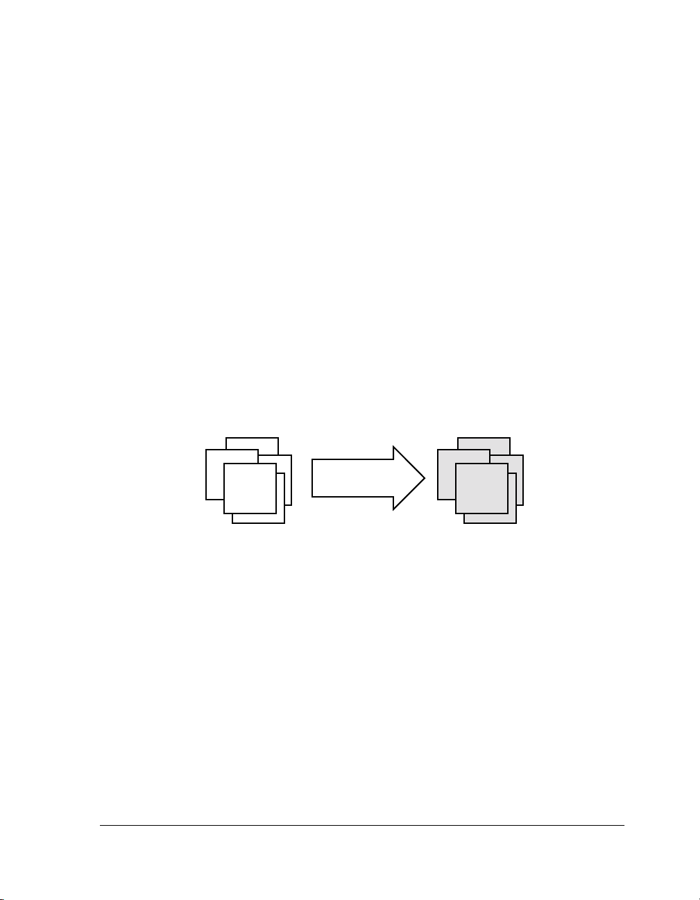
Linking assigns code and data to processor memory. For a simple single-processor architecture, a single .DXE file is generated. A single
invocation of the linker may create multiple executable files (.DXE) for
multiprocessor (MP) architectures. Linking can also produce a shared
memory (.SM) file for an MP system. A large executable can be split into a
smaller executable and overlays (.OVL files), which contain code that is
called in (swapped into internal processor memory) as needed. The linker
(linker.exe) performs this task.
You can run the linker from a command line or from the VisualDSP++
Integrated Development and Debugging Environment (IDDE).
You can load the link output into the VisualDSP++ debugger for simulation, testing, and profiling.
This chapter includes:
• “Linker Operation” on page 2-2
• “Linking Environment” on page 2-6
• “Link Target Description” on page 2-11
• “Passing Arguments for Simulation or Emulation: Blackfin Proces-
sors ONLY” on page 2-29
• “Linker Command-Line Reference” on page 2-30
VisualDSP++ 3.5 Linker and Utilities Manual 2-1
for 16-Bit Processors
Page 38

Linker Operation
Linker Operation
Figure 2-1 illustrates a basic linking operation. The figure shows several
object files (.DOJ) being linked into a single executable file (.DXE). The
Linker Description File (.LDF) directs the linking process.
1.DOJ
2.DOJ
Linker
.DXE
N.DOJ
.LDF
Figure 2-1. Linking Object Files to Produce an Executable File
When developing a new project, use the Expert Linker to generate
the project’s LDF. See Chapter 4, “Expert Linker” for more
information.
In a multiprocessor system, a .DXE file for each processor is generated. For
example, for a two-processor system, you must generate two
.DXE files.
The processors in a multiprocessor architecture may share memory. When
directed by statements in the
.LDF file, the linker produce a shared mem-
ory executable (.SM) file, whose code is used by multiple processors.
Overlay files (.OVL), another linker output, support applications that
require more program instructions and data than the processor’s internal
memory can accommodate. Refer to “Memory Management Using Over-
lays” on page 5-4 for more information.
2-2 VisualDSP++ 3.5 Linker and Utilities Manual
for 16-Bit Processors
Page 39

Linker
Similar to object files, executable files are partitioned into output sections
with unique names. Output sections are defined by the Executable and
Linking Format (ELF) file standard to which VisualDSP++ conforms.
The executable file(s) (.DXE) and auxiliary files (.SM and .OVL) are not
loaded into the processor or burned onto an EPROM. These files are used
to debug the system.
The executable’s input section names and output section names
occupy different namespaces. Because the namespaces are independent, the same section names may be used. The linker uses input
section names as labels to locate corresponding input sections
within object files.
Directing Linker Operation
Linker operations are directed by these options and commands:
• Linker (linker.exe) command-line switches (options). Refer to
“Linker Command-Line Reference” on page 2-30.
• Settings (options) on the Link page of the Project Options dialog
box. See “Project Builds” on page 2-6.
• LDF commands. Refer to “LDF Commands” on page 3-23 for a
detailed description of the LDF commands.
Linker options control how the linker processes object files and library
files. These options specify various criteria such as search directories, map
file output, and dead code elimination. You select linker options via linker
command-line switches or by settings on the Link page of the Project
Options dialog box within the VisualDSP++ environment.
LDF commands in a Linker Description File (.LDF) define the target
memory map and the placement of program sections within processor
memory. The text of these commands provides the information needed to
link your code.
VisualDSP++ 3.5 Linker and Utilities Manual 2-3
for 16-Bit Processors
Page 40

Linker Operation
Using directives in the .LDF file, the linker:
The VisualDSP++ Project window displays the .LDF file as a source
file, though the file provides linker command input.
• Reads input sections in the object files and maps them to output
sections in the executable file. More than one input section may be
placed in an output section.
• Maps each output section in the executable to a memory segment,
a contiguous range of memory addresses on the target processor.
More than one output section may be placed in a single memory
segment.
Linking Process Rules
The linking process observes these rules:
• Each source file produces one object file.
• Source files may specify one or more input sections as destinations
for compiled/assembled object(s).
• The compiler and assembler produce object code with labels that
direct one or more portions to particular output sections.
• As directed by the .LDF file, the linker maps each input section
in the object code to an output section in the
• As directed by the .LDF file, the linker maps each output section
to a memory segment.
• Each input section may contain multiple code items, but a code
item may appear in one input section only.
• More than one input section may be placed in an output section.
• Each memory segment must have a specified width.
2-4 VisualDSP++ 3.5 Linker and Utilities Manual
.DXE file.
for 16-Bit Processors
Page 41

• Contiguous addresses on different-width hardware must reside in
different memory segments.
• More than one output section may map to a memory segment if
the output sections fit completely within the memory segment.
Linker Description File — Overview
Whether you are linking C/C++ functions or assembly routines,
the mechanism is the same. After converting the source files into object
files, the linker uses directives in an
an executable file (.DXE), which may be loaded into a simulator for testing.
.LDF file to combine the objects into
Linker
Each project must include one .LDF file that specifies the linking process
by defining the target memory and mapping the code and data into that
memory. You can write your own .LDF file, or you can modify an existing
file; modification is often the easier alternative when there are few changes
in your system’s hardware or software. VisualDSP++ provides an .LDF file
that supports the default mapping of each processor type.
Similar to an object (.DOJ) file, an executable (.DXE) file consists of
different segments, called output sections. Input section names are
independent of output section names. Because they exist in different
namespaces, input section names can be the same as output section names.
Refer to Chapter 3, “Linker Description File” for further information.
Executable file structure conforms to the Executable and Linkable
Format (ELF) standard.
When developing a new project, use the Expert Linker to generate
the project’s .LDF file, as described in Chapter 4, “Expert Linker”.
VisualDSP++ 3.5 Linker and Utilities Manual 2-5
for 16-Bit Processors
Page 42

Linking Environment
Linking Environment
The linking environment refers to Windows command-prompt windows
and the VisualDSP++ IDDE. At a minimum, run development tools (such
as the linker) via a command line and view output in standard output.
VisualDSP++ provides an environment that simplifies the processor program build process. From VisualDSP++, you specify build options from
the Project Options dialog box and modify files, including the Linker
Description File (.LDF). The Project Options dialog box’s Type option
allows you to choose whether to build a library (.DLB) file, an executable
(.DXE) file, or an image file (.LDR or others). Error and warning messages
appear in the Output window.
Project Builds
The linker runs from an operating system command line, issued from the
VisualDSP++ IDDE or a command prompt window. Figure 2-2 shows the
VisualDSP++ environment with the Project window and an .LDF file open
in an editor window.
The VisualDSP++ IDDE provides an intuitive interface for processor programming. When you open VisualDSP++, a work area contains everything
needed to build, manage, and debug a DSP project. You can easily create
or edit an .LDF file, which maps code or data to specific memory segments
on the target.
2-6 VisualDSP++ 3.5 Linker and Utilities Manual
For information about the VisualDSP++ environment, refer to the
VisualDSP++ User’s Guide for the appropriate target architecture or
online Help. Online Help provides powerful search capabilities. To
obtain information on a code item, parameter, or error, select text
in an VisualDSP++ IDDE editor window or Output window and
press the keyboard’s F1 key.
for 16-Bit Processors
Page 43

Linker
Figure 2-2. VisualDSP++ Environment
Within VisualDSP++, specify tool settings for project builds. Modify
linker options via the Link tab of the Project Options dialog box
(Figure 2-3). Choosing a Category from the pull-down list at the top of
the Link tab presents different panes of options.
There are four sub-pages you can access—General, LDF Preprocessing,
Elimination, and Processor. Almost every setting option has a corresponding compiler command-line switch described in “Linker
Command-Line Switches” on page 2-34. The Additional options field in
VisualDSP++ 3.5 Linker and Utilities Manual 2-7
for 16-Bit Processors
Page 44

Linking Environment
Figure 2-3. Main Link Tab with Category Selections
each sub-page is used to enter the appropriate file names and options that
do not have corresponding controls on the Link sub-page but are available
as compiler switches.
Due to different processor architectures, Blackfin processors, ADSP-218x
DSPs and ADSP-219x DSPs provide different Link tab selection options.
Use the VisualDSP++ context-sensitive online Help for each target architecture to select information on linker options you can specify in
VisualDSP++.
2-8 VisualDSP++ 3.5 Linker and Utilities Manual
for 16-Bit Processors
Page 45

Expert Linker
The VisualDSP++ IDDE features an interactive tool, Expert Linker,
to map code or data to specific memory segments. When developing
a new project, use the Expert Linker to generate the
Expert Linker graphically displays the .LDF information (object files, LDF
macros, libraries, and a target memory description). With Expert Linker,
use drag-and-drop operations to arrange the object files in a graphical
memory mapping representation. When you are satisfied with the memory
layout, generate the executable file (
.DXE).
Figure 2-4 shows the Expert Linker window (for Blackfin processors),
which comprises two panes: Input Sections and Memory Map (output
sections). Refer to Chapter 4, “Expert Linker”, for detailed information.
.LDF file.
Linker
Figure 2-4. Expert Linker Window
VisualDSP++ 3.5 Linker and Utilities Manual 2-9
for 16-Bit Processors
Page 46

Linking Environment
Linker Warning and Error Messages
Linker messages are written to the VisualDSP++ Output window
(standard output when the linker is run from a command line). Messages
describe problems the linker encountered while processing the
Warnings indicate processing errors that do not prevent the linker from
producing a valid output file, such as unused symbols in your code. Errors
are issued when the linker encounters situations that prevent the production of a valid output file.
Typically, these messages include the name of the .LDF file, the line number containing the message, a six-character code, and a brief description of
the condition.
Example
>linker -T nofile.ldf
[Error li1002] The linker description file 'NOFILE.LDF'
could not be found
Linker finished with 1 error(s) 0 warning(s)
.LDF file.
Interpreting Linker Messages
Within VisualDSP++, the Output window’s Build tab displays project
build status and error messages. In most cases, double-click a message displays the line in the source file causing the problem. You can access
descriptions of linker messages from VisualDSP++ online Help by selecting a six-character code (for example, li1002) and pressing the F1 key.
Some build errors, such as a reference to an undefined symbol, do not correlate directly to source files. These errors often stem from omissions in
the .LDF file.
For example, if an input section from the object file is not placed by the
.
LDF file, a cross-reference error occurs at every object that refers to labels
in the missing section. Fix this problem by reviewing the .LDF file and
specifying all sections that need placement. For more information, refer to
the VisualDSP++ 3.5 User’s Manual for 16-Bit Processors or online Help.
2-10 VisualDSP++ 3.5 Linker and Utilities Manual
for 16-Bit Processors
Page 47

Link Target Description
Before defining the system’s memory and program placement with linker
commands, analyze the target system to ensure you can describe the target
in terms the linker can process. Then, produce an .LDF file for your project
to specify these system attributes:
• Physical memory map
• Program placement within the system’s memory map
Linker
Be sure to understand the processor’s memory architecture, which is
described in the processor’s Hardware Reference manual and in its data
sheet.
If the project does not include an .LDF file, the linker uses a default
.LDF file for the processor that matches the -proc <processor>
switch on the linker’s command line (or the Processor selection
specified on the Project page of the Project Options dialog box in
the VisualDSP++ IDDE). The examples in this manual are for
ADSP-BF535 processors.
Representing Memory Architecture
The .LDF file’s MEMORY{} command is used to represent the memory
architecture of your DSP system. The linker uses this information to place
the executable file into the system’s memory.
Perform the following tasks to write a MEMORY{} command:
• Memory Usage. List the ways your program uses memory in your
system. Typical uses for memory segments include interrupt tables,
initialization data, program code, data, heap space, and stack space.
Refer to “Specifying the Memory Map” on page 2-18.
VisualDSP++ 3.5 Linker and Utilities Manual 2-11
for 16-Bit Processors
Page 48

Link Target Description
• Memory Characteristics. List the types of memory in your DSP
system and the address ranges and word width associated with each
memory type. Memory type is defined as RAM or ROM.
• MEMORY{} Command. Construct a MEMORY{} command to combine the information from the previous two lists and to declare
your system’s memory segments.
For complete information, refer to “MEMORY{}” on page 3-29.
ADSP-BF535 Processor Memory Architecture Overview
As an example, this section describes the Blackfin ADSP-BF535 memory
architecture and memory map organization.
The ADSP-BF535 processor includes the L1 memory subsystem with a
16Kbyte instruction SRAM/cache, a dedicated 4Kbyte data scratchpad,
and a 32Kbyte data SRAM/cache configured as two independent 16Kbyte
banks (memories). Each independent bank can be configured as SRAM or
cache.
The ADSP-BF535 processor also has an L2 SRAM memory that provides
2 Mbits (256 Kbytes) of memory. The L2 memory is unified; that is, it is
directly accessible by the instruction and data ports of the ADSP-BF535
processor. The L2 memory is organized as a multi-bank architecture of
single-ported SRAMs (there are eight sub-banks in L2), such that simultaneous accesses by the core and the DMA controller to different banks can
occur in parallel.
Figure 2-5 shows the ADSP-BF535 system block diagram.
Other processors in the Blackfin family (ADSP-BF531/2/3 and
ADSP-561) have very different memory architectures. Refer to
Hardware Reference manuals of target processors for appropriate
information.
2-12 VisualDSP++ 3.5 Linker and Utilities Manual
for 16-Bit Processors
Page 49

PROC ES SOR
Linker
0
1
D
D
L
32 K B
BLOCK 7
SRAM
MEMORY
L
2
2
3
3
4K S RAM
L1 DATA MEMORY
CORED0 BUS CORE D1 BUS CORE I BUS
CORE L2 BUS SYS L2 BUS
256 KBL2 SRAM
32 KB
BLOCK 0
SRA M
ME MOR Y
DCACHE/SRAM
...
0
1
B
D
A
S
2
3
SYSTEM BUS INTERFACE UNIT (SBIU)
A
D
D
2
2
3
3
MEMORY
MANAGE MENT
UNI T
CONTROL
EBIU
B
A
D
I
I
4
2
6
3
ICACHE/SRAM
L1 INS TRUCTION MEMORY
SY SL1 BUS
PER I P HE RA L A CC E SS B U S
DMA ACCES S BUS (DAB)
EXTE RNA L ACC ESS B US
EXTERNAL MASTERED BUS
PCI
(PAB)
(EAB)
(E MB)
AS YN CHR O N OU S
AND
SYNCHRONOUS
MEMORY
PCI MEMOR Y
AND I/O
Figure 2-5. ADSP-BF535 System Block Diagram
VisualDSP++ 3.5 Linker and Utilities Manual 2-13
for 16-Bit Processors
Page 50

Link Target Description
The device has two ports to the L2 memory: one dedicated to core
requests, and the other dedicated to system DMA and PCI requests. The
processor units can process 8-, 16-, 32-, or 40-bit data, depending on the
type of function being performed.
Memory ranges are listed in Table 2-1. Address ranges that are not listed
are reserved.
Table 2-1. ADSP-BF535 Processor Memory Map Addresses
Memory Range Range Description
0xFFE00000 –0xFFFFFFFF
0xFFC00000 –0xFFDFFFFF
0xFFB00000 –0xFFB00FFF
0xFFA00000 –0xFFA03FFF
0xFF900000 –0xFF903FFF
0xFF800000 –0xFF803FFF
0xF0040000 –0xFF7FFFFF
0xF0000000 –0xF003FFFF
0xEF000400 –0xEFFFFFFF
0xEF000000 –0xEF0003FF
0x00000000 –0xEEFFFFFF
Core MMR registers (2MB)
System MMR registers (2MB)
Scratchpad SRAM (4K)
Instruction SRAM (16K)
Data Memory Bank 2 SRAM (16K)
Data Memory Bank 1 SRAM (16K)
Reserved
L2 Memory Bank SRAM (256K)
Reserved
Boot ROM (1K)
External memory
The MEMORY section in Listing 2-1 on page 2-24 assumes that only L1 and
L2 SRAMs are available and that L1 is unused. Refer to the VisualDSP++
C/C++ Compiler and Library Manual for Blackfin Processors and the appropriate Hardware Reference for information about cache configuration.
information about your target processor’s memory organization.
2-14 VisualDSP++ 3.5 Linker and Utilities Manual
for 16-Bit Processors
See the Memory chapter in an appropriate Hardware Reference for
Page 51

ADSP-218x DSP Core Architecture Overview
Figure 2-6 shows the ADSP-218x DSP core architecture.
POW ER-DO WN
CONTRO L
DATA ADDRESS
GENERA TORS
DAG1
DAG2
ARITHMETIC UNITS
ALU
ADSP-2100 BASE
ARCHITECTURE
PROGRAM
SEQUENCER
SHIFTERMAC
MEMORY
PROGRAM
MEMORY
UP TO
48K 24-BIT
PROGRAM MEMORY ADDRESS
DATA MEMORY ADDRESS
PROGRAM MEMORY DATA
DATA MEM ORY DATA
SPORT0
MEMORY
56K
SERIAL PORTS
SPORT1
DATA
UP TO
16-BIT
PROGRAMMABLE
I/O
AND
FLAG S
TIMER
Linker
FULL MEMORY MODE
EXTERNAL
ADDRESS
BUS
EXTERNAL
DATA
BUS
BYTE DMA
CONTROLLER
OR
EXTERNAL
DATA
BUS
INTERNAL
DMA
PORT
HOST MODE
Figure 2-6. ADSP-218x DSP Functional Block Diagram
ADSP-218x DSPs use a modified Harvard architecture in which Data
Memory stores data and Program Memory stores both instructions and
data. All ADSP-218x processors contain on-chip RAM that comprises a
portion of the Program Memory space and Data Memory space. (Program
Memory and Data Memory are directly addressable off-chip.) The speed
of the on-chip memory allows the processor to fetch two operands (one
from Data Memory and one from Program Memory) and an instruction
(from Program Memory) in a single cycle. In each ADSP-218x processor,
five on-chip buses connect internal memory with the other functional
units. A single external address bus (14 bits) and a single external data bus
(24 bits) are extended off-chip; these buses can be used for either Program
or Data Memory accesses.
VisualDSP++ 3.5 Linker and Utilities Manual 2-15
for 16-Bit Processors
Page 52

Link Target Description
All ADSP-218x DSPs (except for the ADSP-2181 and ADSP-2183 DSPs)
can be configured in either a Host Mode or a Full Memory Mode. In Host
Mode, each processor has an Internal DMA (IDMA) port for connection
to external host systems. The IDMA port provides transparent, direct
access to the DSP’s on-chip Program and Data RAM. Since the
ADSP-2181 and ADSP-2183 DSPs have complete address, data, and
IDMA busses, these two processors provide both IDMA and BDMA functionality concurrently to provide greater system functionality without
additional external logic.
In Full Memory Mode, ADSP-218x processors have complete use of the
external address and data buses. In this mode, the processors behave as
ADSP-2181 and ADSP-2183 processors with the IDMA port removed.
Program Memory (Full Memory Mode) is a 24-bit-wide space for storing
instruction opcodes and data. The ADSP-218x DSPs have up to 48K
words of Program Memory RAM on chip, and the capability of accessing
up to two 8K external memory overlay spaces by means of the external
data bus. Program Memory (Host Mode) allows access to all internal
memory. External overlay access is limited by a single external address line
(A0). External program execution is not available in the host mode
because of a restricted data bus that is only 16 bits wide.
Data Memory (Full Memory Mode) is a 16-bit-wide space used for storing data variables and memory-mapped control registers. For example,
ADSP-218xN DSPs have up to 56K words of Data Memory RAM
on-chip. Part of this space is used by 32 memory-mapped registers. Support also exists for up to two 8K external memory overlay spaces through
the external data bus. All internal accesses complete in one cycle. Data
Memory (Host Mode) allows access to all internal memory. External overlay access is limited by a single external address line (A0).
The ADSP-218x processors support memory-mapped peripherals with
programmable wait state generation through a dedicated 2048 location
I/O Memory space.
2-16 VisualDSP++ 3.5 Linker and Utilities Manual
for 16-Bit Processors
Page 53

ADSP-219x DSP Architecture Overview
Figure 2-7 shows the ADSP-219x DSP core architecture. The ADSP-219x
architecture is code-compatible with ADSP-218x DSPs. However, the
ADSP-219x architecture has several enhancements over the ADSP-218x
architecture, including single or dual-core architecture, three computational units, two data address generators, a program sequencer, a JTAG
port, a 24-bit address reach, and an instruction cache. These enhancements make ADSP-219x DSPs more flexible and easier to program.
Linker
Figure 2-7. ADSP-219x DSP Basic Functional Block Diagram
For example, the ADSP-2191M DSP has a single-core architecture that
integrates 64K words of on-chip memory configured as 32K words
(24-bit) of program RAM, and 32K words (16-bit) of data RAM.
Power-down circuitry is also provided to reduce power consumption.
VisualDSP++ 3.5 Linker and Utilities Manual 2-17
for 16-Bit Processors
Page 54

Link Target Description
The two address buses (PMA and DMA) share a single external address
bus to allow memory to be expanded off-chip, and the two data buses
(PMD and DMD) share a single external data bus. Boot memory space
and I/O memory space also share the external buses. Program memory can
store both instructions and data to enable the ADSP-2191M DSP to fetch
two operands in a single cycle, one from program memory and one from
data memory. The DSP’s dual memory buses also let the ADSP-219x core
fetch an operand from data memory and the next instruction from program memory in a single cycle.
Specifying the Memory Map
A DSP program must conform to the constraints imposed by the processor’s data path (bus) widths and addressing capabilities. The following
steps show an .LDF file for a hypothetical project. This file specifies several
memory segments that support the SECTIONS{} command, as shown in
“SECTIONS{}” on page 3-42.
The three steps involved in allocating memory are:
• “Memory Usage” on page 2-18
• “Memory Characteristics” on page 2-20
• “Linker MEMORY{} Command in .LDF File” on page 2-24
Memory Usage
Input section names are generated automatically by the compiler or are
specified in the assembly source code. The
.LDF file defines memory seg-
ment names and output section names. The default .LDF file handles all
compiler-generated input sections (refer to the “Input Section” column in
tables below). The produced .DXE file has a corresponding output section
for each input section. Although programmers typically do not use output
section labels, the labels are used by downstream tools.
2-18 VisualDSP++ 3.5 Linker and Utilities Manual
for 16-Bit Processors
Page 55

Linker
Use the ELF file dumper utility (elfdump.exe) to dump contents of an
output section (for example, data1) of an executable file. See “elfdump –
ELF File Dumper” on page B-1 for information about this utility.
The following tables show how input sections, output sections, and memory segments correspond in the default LDFs for appropriate target
processor architectures.
• Table 2-2 shows section mapping in the default .LDF file for
ADSP-2191 DSPs (as an example for the ADSP-218x/9x DSPs)
• Table 2-3 shows section mapping in the default .LDF file for
ADSP-BF535 processor (as an example for Blackfin processors)
erence for details.
Typical uses for memory segments include interrupt tables, initialization
data, program code, data, heap space, and stack space.
Table 2-2. Section Mapping in the Default ADSP-2191 LDF
Input Section Output Section Memory Segment
program program_dxe mem_code
data1 data1_dxe mem_data1
data2 data2_dxe mem_data2
N/A sec_stack mem_stack
N/A sec_heap mem_heap
Refer to your processor’s default .LDF file and to the Hardware Ref-
VisualDSP++ 3.5 Linker and Utilities Manual 2-19
for 16-Bit Processors
Page 56

Link Target Description
Table 2-3. Section Mapping in the Default ADSP-BF535 LDF
Input Section Output Section Memory Section
program dxe_program MEM_PROGRAM
data1 dxe_program MEM_PROGRAM
constdata dxe_program MEM_PROGRAM
heap dxe_heap MEM_HEAP
stack dxe_stack MEM_STACK
sysstack dxe_sysstack MEM_SYSSTACK
bootup dxe_bootup MEM_BOOTUP
ctor dxe_program MEM_PROGRAM
argv dxe_argv MEM_ARGV
objects into L1 memories when they are configured as SRAM.
Memory Characteristics
This section provides an overview of basic memory information (including
addresses and ranges) for target architectures.
Blackfin Processors
Table 2-4 lists memory ranges for the ADSP-BF535 processors. Address
ranges that are not listed are reserved. Blackfin processors have a 32-bit
For Blackfin processors, you can modify your .LDF file to place
address range to support memory addresses from
0x0 to 0xFFFF FFFF.
Figure 2-8 on page 2-22 shows the ADSP-BF535 processor memory archi-
tecture. Other Blackfin processors have different memory architectures.
Refer to Hardware References of target processors for appropriate
information.
2-20 VisualDSP++ 3.5 Linker and Utilities Manual
for 16-Bit Processors
Page 57

Table 2-4. ADSP-BF535 Processor Memory Map Addresses
Memory Range Range Description
Linker
0xFFE00000 –0xFFFFFFFF
0xFFC00000 –0xFFDFFFFF
0xFFB00000 –0xFFB00FFF
0xFFA00000 –0xFFA03FFF
0xFF900000 –0xFF903FFF
0xFF800000 –0xFF803FFF
0xF0040000 –0xFF7FFFFF
0xF0000000 –0xF003FFFF
0xEF000400 –0xEFFFFFFF
0xEF000000 –0xEF0003FF
0x00000000 –0xEEFFFFFF
Core MMR registers (2MB)
System MMR registers (2MB)
Scratchpad SRAM (4K)
Instruction SRAM (16K)
Data Memory Bank 2 SRAM (16K)
Data Memory Bank 1 SRAM (16K)
Reserved
L2 Memory Bank SRAM (256K)
Reserved
Boot ROM (1K)
Unpopulated
The MEMORY section in Listing 2-1 on page 2-24 assumes that only L1 and
L2 SRAMs are available and that L1 is unused. Refer to the VisualDSP++
C/C++ Compiler and Library Manual for Blackfin Processors and the appropriate Hardware Reference for information about cache configuration.
ADSP-218x and ADSP-219x DSPs
ADSP-218x and ADSP-219x DSPs have a 24-bit address range to support
memory addresses from 0x0 to 0xFFFFFF. Memory type is defined by two
characteristics:
PM or DM, and RAM or ROM. Some portions of the DSP mem-
ory are reserved. Refer to your DSP’s Hardware Reference for details.
VisualDSP++ 3.5 Linker and Utilities Manual 2-21
for 16-Bit Processors
Page 58

Link Target Description
Figure 2-8. ADSP-BF535 Processor Memory Architecture
2-22 VisualDSP++ 3.5 Linker and Utilities Manual
for 16-Bit Processors
Page 59

Linker
ADSP-218x DSPs provide a variety of memory and peripheral interface
options. The key functional groups are Program Memory, Data Memory,
Byte Memory, and I/O. Refer to Figure 2-9 for PM and DM memory
allocations in the ADSP-2186 DSP.
0X3FFF
0X2000
0X1FFF
0X0000
PROGRAM MEMORY
MODEB = 1
RE SERV ED
EXTERNAL PM
0X3FFF
0X2000
0X1FFF
0X0000
PROGRAM MEMORY
MODEB = 0
PM OVERLAY 1, 2
(EXTERNAL PM)
PM OVERLA Y 0
(RESERVED)
INTERNAL PM
0X3FFF
0X3FE0
0X3FDF
0X2000
0X1FFF
0X0000
DATA MEMORY
32 MEMORY-MAPPED
CONTROL REGIST ERS
INTERNAL DM
DM OVERLAY 1,2
(EXTERNAL DM)
DM OVERLAY 0
(RESERVED)
Figure 2-9. ADSP-2186 DSP Memory Architecture
ADSP-2191x DSPs provide various memory allocations. Refer to
Figure 2-10 for PM and DM memory allocations in the ADSP-2191M
DSP. It provides 64K words of on-chip SRAM memory. This memory is
divided into four 16K blocks located on memory Page 0 in the DSP’s
memory map. In addition to addressing internal and external memory
space, ADSP-2191M DSPs can address two additional and separate
off-chip memory spaces: I/O space and boot space.
As shown, the DSP’s two internal memory blocks populate all of Page 0.
The entire DSP memory map consists of 256 pages (Pages 0–255), and
each page is 64K words long. External memory space consists of four
memory banks (banks 0–3) and supports a wide variety of SRAM memory
devices. Each bank is selectable with the memory select pins (MS3–0) and
has configurable page boundaries, wait states, and wait state modes. The
1K word of on-chip boot ROM populates the top of Page 255 while the
VisualDSP++ 3.5 Linker and Utilities Manual 2-23
for 16-Bit Processors
Page 60

Link Target Description
MEMORY SELECTS (MS)
FOR PORTIONS OF THE
MEMORY MAP APPEAR
WITH THE SELECTED
MEMORY.
I/O MEMORY
16- BIT
1K W ORD
PAG ES 8–255
1K W ORD
PAGES 0–7
EXTERNAL
(IO MS )
INTERNAL
ADDRESS
0x03 FFFF
0x00 2000
0x00 0000
INTERNAL
MEMORY
EXTER NAL
MEMORY
(16- B IT)
INTERNAL
MEMORY
MEMORY
PAGES
PAGE 255
PAG ES 192–254
PAG ES 128–191
PAG ES 64–127
PAG ES 1–63
PAGE 0
RESERVED
BOOT ROM, 24-BIT
BANK3
(M S3)
BANK2
(M S2)
BANK1
(M S1)
BANK0
(M S0)
BLOCK1, 16-BIT
BLOCK0, 24-BIT
ADDRESS64K W ORD
0xFF FFFF
0xFF F400
0xFF 0000
0xC0 0000
0x80 0000
0x40 0000
0x01 0000
0x00 8000
0x00 0000
LOWER PAGE BOUNDARIES
ARE CONFIGURABLE FOR
BANKS OF EX TE RNAL MEMORY.
BOUNDARIES SHOWN ARE
BANK SIZES AT RESET.
ADDRESS
0xFE FFFF
BOOT
MEMORY
16- BIT
(BM S)
64K W ORD
PAG ES 1–254
0x01 0000
Figure 2-10. ADSP-2191M DSP Memory Architecture
remaining 254 pages are addressable off-chip. I/O memory pages differ
from external memory pages in that I/O pages are 1K word long, and the
external I/O pages have their own select pin (IOMS). Pages 0–7 of I/O
memory space reside on-chip and contain the configuration registers for
the peripherals. Both the core and DMA-capable peripherals can access
the DSP’s entire memory map.
Linker MEMORY{} Command in .LDF File
Referring to information in sections “Memory Usage” and “Memory
Characteristics”, you can specify the target’s memory with the MEMORY{}
command for any of the four target processor architectures (Listing 2-1).
Listing 2-1. Blackfin Processors -- MEMORY{} Command Code
MEMORY /* Define/label system memory */
{ /* List of global Memory Segments */
MEM_L2
2-24 VisualDSP++ 3.5 Linker and Utilities Manual
for 16-Bit Processors
Page 61

Linker
{ TYPE(RAM) START(0xF0000000) END(0xF002FFFF) WIDTH(8) }
MEM_HEAP
{ TYPE(RAM) START(0xF0030000) END(0xF0037FFF) WIDTH(8) }
MEM_STACK
{ TYPE(RAM) START(0xF0038000) END(0xF003DFFF) WIDTH(8) }
MEM_SYSSTACK
{ TYPE(RAM) START(0xF003E000) END(0xF003FDFF) WIDTH(8) }
MEM_ARGV
{ TYPE(RAM) START(0xF003FE00) END(0xF003FFFF) WIDTH(8) }
}
Listing 2-2. ADSP-2191 DSPs -- MEMORY{} Command
MEMORY /* Define and label system memory */
{ /* List of global memory segments */
seg_rth {TYPE(PM RAM) START(0x000000) END(0x000241) WIDTH(24)}
seg_code {TYPE(PM RAM) START(0x000242) END(0x007fff) WIDTH(24)}
seg_data1 {TYPE(DM RAM) START(0x008000) END(0x00ffff) WIDTH(16)}
}
write a MEMORY{} command and to the following discussion of the
SECTIONS{} command. The SECTIONS{} command is not atomic; it
can be interspersed with other directives, including location
counter information. You can define new symbols within the .LDF
file.
These example define the starting stack address, the highest possible stack address, and the heap’s starting location and size. These
newly created symbols are entered in the executable’s symbol table.
VisualDSP++ 3.5 Linker and Utilities Manual 2-25
for 16-Bit Processors
The above examples apply to the preceding discussion of how to
Page 62

Link Target Description
Placing Code on the Target
Use the SECTIONS{} command to map code and data to the physical memory of a processor in a DSP system.
To write a SECTIONS{} command:
1. List all input sections defined in the source files.
• Assembly files. List each assembly code .SECTION directive,
identify its memory type (PM or CODE, or DM or DATA), and note
when location is critical to its operation. These .SECTIONS portions include interrupt tables, data buffers, and on-chip code or
data.
• C/C++ source files. The compiler generates sections with the
name “program” or “code” for code, and the names “data1” and
“data2” for data. These sections correspond to your source
when you do not specify a section by means of the optional
section() extension.
2. Compare the input sections list to the memory segments specified
in the MEMORY{} command. Identify the memory segment into
which each .SECTION must be placed.
3. Combine the information from these two lists to write one or more
SECTIONS{} commands in the .LDF file.
Listing 2-3 presents a SECTIONS{} command that would work with the
MEMORY{} command in Listing 2-1.
2-26 VisualDSP++ 3.5 Linker and Utilities Manual
SECTIONS{} commands must appear within the context of
PROCESSOR{} or SHARED_MEMORY() command.
the
for 16-Bit Processors
Page 63

Listing 2-3. Blackfin SECTIONS{} Command in the .LDF File
SECTIONS
{ /* List of sections for processor P0 */
dxe_L2
{
INPUT_SECTION_ALIGN(2)
/* Align all code sections on 2 byte boundary */
INPUT_SECTIONS( $OBJECTS(program) $LIBRARIES(program))
INPUT_SECTION_ALIGN(1)
INPUT_SECTIONS( $OBJECTS(data1) $LIBRARIES(data1))
INPUT_SECTION_ALIGN(1)
INPUT_SECTIONS( $OBJECTS(constdata)
$LIBRARIES(constdata))
INPUT_SECTION_ALIGN(1)
INPUT_SECTIONS( $OBJECTS(ctor) $LIBRARIES(ctor) )
} >MEM_L2
Linker
stack
{
ldf_stack_space = .;
ldf_stack_end =
ldf_stack_space + MEMORY_SIZEOF(MEM_STACK) - 4;
} >MEM_STACK
sysstack
{
ldf_sysstack_space = .;
ldf_stack_end =
ldf_stack_space + MEMORY_SIZEOF(MEM_STACK) - 4;
} >MEM_SYSSTACK
heap
{ /* Allocate a heap for the application */
ldf_heap_space = .;
ldf_heap_end =
ldf_heap_space + MEMORY_SIZEOF(MEM_HEAP) - 1;
ldf_heap_length = ldf_heap_end - ldf_heap_space;
} >MEM_HEAP
VisualDSP++ 3.5 Linker and Utilities Manual 2-27
for 16-Bit Processors
Page 64

Link Target Description
argv
{ /* Allocate argv space for the application */
ldf_argv_space = .;
ldf_argv_end =
ldf_argv_space + MEMORY_SIZEOF(MEM_ARGV) - 1;
ldf_argv_length =
ldf_argv_end - ldf_argv_space;
} >MEM_ARGV
} /* end SECTIONS */
Listing 2-4. ADSP-218x/9x SECTIONS{} Command in the .LDF File
SECTIONS
{ /* List of sections for processor P0 */
sec_rth {INPUT_SECTIONS ( $OBJECTS(rth))} > seg_rth
sec_code {INPUT_SECTIONS ( $OBJECTS(code)} > seg_code
sec_code2 {INPUT_SECTIONS ( $OBJECTS(y_input)} > seg_code
sec_data1 {INPUT_SECTIONS ( $OBJECTS(data1))} > seg_data1
}
}
2-28 VisualDSP++ 3.5 Linker and Utilities Manual
for 16-Bit Processors
Page 65

Passing Arguments for Simulation or Emulation: Blackfin Processors ONLY
To support simulation and emulation in Blackfin processors, the linker
should obtain the start address and buffer length of the argument list from
the ARGV memory segment of the .LDF file (refer to “Example 1 – Basic
.LDF File for Blackfin Processors” on page 3-4).
To set the address:
1. In the MEMORY{} section, add a line to define the MEM_ARGV section.
2. Add a command to define the ARGV section and the values for
ldf_argv_space, ldf_argv_length, and ldf_argv_end.
Refer to the VisualDSP++ 3.5 User's Manual for 16-Bit Processors or online
Help for information about the simulator and command-line arguments.
Linker
VisualDSP++ 3.5 Linker and Utilities Manual 2-29
for 16-Bit Processors
Do not use command-line arguments for linked programs without
first modifying the .LDF file to allocate a buffer suitable for your
application.
Page 66

Linker Command-Line Reference
Linker Command-Line Reference
This section provides reference information, including:
• “Linker Command-Line Syntax” on page 2-30
• “Linker Command-Line Switches” on page 2-34
When you use the linker via the VisualDSP++ IDDE, the settings
on the Link tab of the Project Options dialog box correspond
to linker command-line switches. VisualDSP++ calls the linker
with these switches when linking your code. For more information,
refer to the VisualDSP++ 3.5 User's Manual for 16-Bit Processors
and VisualDSP++ online Help.
Linker Command-Line Syntax
Run the linker by using one of the following normalized formats of the
linker command line.
linker -proc processor -switch [-switch …] object [object …]
linker -T target.ldf -switch [-switch …] object [object …]
The command line must have at least one object (an object file name).
Other switches are optional, and some commands are mutually exclusive.
The linker command requires -proc processor or a -T <ldf name>
for the link to proceed. If the command line does not include
-proc processor, the .LDF file following the -T switch must con-
tain a
-Darchitecture command.
Example
The following is an example linker command.
linker -proc ADSP-BF535 p0.doj -T target.ldf -t -o program.dxe
2-30 VisualDSP++ 3.5 Linker and Utilities Manual
for 16-Bit Processors
Page 67

Linker
When using the linker’s command line, you should be familiar with the
following topics:
Command-Line Object Files
The command line must list at least one (typically more) object file(s)
to be linked together. These files may be of several different types.
Use -proc processor instead of the deprecated -Darchitecture on
the command line to select the target processor. See Table 2-6 on
page 2-36 for more information.
The linker command line (except for file names) is case sensitive.
For example, linker -t differs from linker -T.
• “Command-Line Object Files” on page 2-31
• “Command-Line File Names” on page 2-32
• “Object File Types” on page 2-34
• Standard object files (.DOJ) produced by the assembler
• One or more libraries (archives), each with a .DLB extension.
Examples include the C run-time libraries and math libraries
included with VisualDSP++. You may create libraries of common
or specialized objects. Special libraries are available from DSP
algorithm vendors. For more information, see Chapter 6,
“Archiver”.
• An executable (.DXE) file to be linked against. Refer to
$COMMAND_LINE_LINK_AGAINST in “Built-In LDF Macros” on
page 3-21.
VisualDSP++ 3.5 Linker and Utilities Manual 2-31
for 16-Bit Processors
Page 68

Linker Command-Line Reference
Object File Names
Object file names are not case sensitive. An object file name may include:
• The drive, directory path, file name, and file extension
• The directory path may be an absolute path or a path relative to the
directory where the linker is invoked
• Long file names enclosed within straight quotes
If the file exists before the link begins, the linker opens the file to verify its
type before processing the file. Table 2-5 lists valid file extensions used by
the linker.
Command-Line File Names
Some linker switches take a file name as a parameter. Table 2-5 lists the
types of files, names, and extensions that the linker expects on file name
arguments. The linker follows the conventions for file extensions in
Table 2-5.
Table 2-5. File Extension Conventions
Extension File Description
.DLB Library (archive) file
.DOJ Object file
.DXE Executable file
.LDF Linker Description File
.OVL Overlay file
.SM Shared memory file
2-32 VisualDSP++ 3.5 Linker and Utilities Manual
for 16-Bit Processors
Page 69

Linker
The linker supports relative and absolute directory names, default directories, and user-selected directories for file search paths. File searches occur
in the following order.
1. Specified path – If the command line includes relative or absolute
path information on the command line, the linker searches that
location for the file.
2. Specified directories – If you do not include path information
on the command line and the file is not in the default directory,
the linker searches for the file in the search directories specified
with the -L (path) command-line switch, and then searches directories specified by SEARCH_DIR commands in the .LDF file.
Directories are searched in order of appearance on the command
line or in the .LDF file.
3. Default directory – If you do not include path information in the
.LDF file named by the -T switch, the linker searches for the .LDF
file in the current working directory. If you use a default .LDF file
(by omitting LDF information in the command line and instead
specifying -proc <processor>), the linker searches in the processor-specific LDF directory; for example, ...\$ADI_DSP\Blackfin\ldf.
For more information on file searches, see “Built-In LDF Macros” on
page 3-21.
When providing input or output file names as command-line parameters:
• Use a space to delimit file names in a list of input files.
• Enclose file names that contain spaces within straight quotes; for
example, “
long file name”.
• Include the appropriate extension to each file. The linker opens
existing files and verifies their type before processing. When the
linker creates a file, it uses the file extension to determine the type
of file to create.
VisualDSP++ 3.5 Linker and Utilities Manual 2-33
for 16-Bit Processors
Page 70

Linker Command-Line Reference
Object File Types
The linker handles an object (file) by its file type. File type is determined
by the following rules.
• Existing files are opened and examined to determine their type.
Their names can be anything.
• Files created during the link are named with an appropriate extension and are formatted accordingly. A map file is formatted as text
and is given an .XML extension. An executable is written in the ELF
format and is given a .DXE extension.
The linker treats object (.DOJ) and library (.DLB) files that appear on the
command line as object files to be linked. The linker treats executable
(.DXE) and shared memory (.SM) files on the command line as executables
to be linked against.
For more information on objects, see the $COMMAND_LINE_OBJECTS macro.
For information on executables, see the $COMMAND_LINE_LINK_AGAINST
macro. Both are described in “Built-In LDF Macros” on page 3-21.
If link objects are not specified on the command line or in the .LDF file,
the linker generates appropriate informational or error messages.
Linker Command-Line Switches
This section describes the linker’s command-line switches. Table 2-6 on
page 2-36 briefly describes each switch with regard to case sensitivity,
equivalent switches, switches overridden or contradicted by the one
described, and naming and spacing constraints for parameters.
The linker provides switches to select operations and modes. The standard
switch syntax is:
-switch [argument]
2-34 VisualDSP++ 3.5 Linker and Utilities Manual
for 16-Bit Processors
Page 71

Rules
• Switches may be used in any order on the command line. Items in
brackets [] are optional. Items in italics are user-definable and are
described with each switch.
• Path names may be relative or absolute.
• File names containing white space or colons must be enclosed by
double quotation marks, though relative path names such as
..\..\test.dxe do not require double quotation marks.
Linker
Example
linker p0.doj p1.doj p2.doj -T target.ldf -t -o program.dxe
Note the difference between the -T and the -t switches. The command
calls the linker as follows:
Different switches require (or prohibit) white space between the
switch and its parameter.
• p0.doj, p1.doj, and p2.doj
Links three object files into an executable.
• -T target.ldf
Uses a secondary .LDF file to specify executable program
placement.
• -t
Turns on trace information, echoing each link object’s name to
stdout as it is processed.
• -o program.dxe
Specifies a name of the linked executable.
Typing linker without any switches displays a summary of command-line
options. Using no switches is the same as typing linker -help.
VisualDSP++ 3.5 Linker and Utilities Manual 2-35
for 16-Bit Processors
Page 72

Linker Command-Line Reference
Linker Switch Summary
Table 2-6 briefly describes each linker switch. Each individual switch is
described in detail following this table. See “Project Builds” on page 2-6
for information on the VisualDSP++ Project Options dialog box.
Table 2-6. Linker Command-Line Switches – Summary
Switch Description More Info
@file Uses the specified file as input on the command
on page 2-38
line.
-DprocessorID Specifies the target processor ID. The use of
-proc processorID is recommended.
-L path Adds the path name to search libraries for objects on page 2-39
-M Produces dependencies. on page 2-39
-MM Builds and produces dependencies. on page 2-39
-Map file Outputs a map of link symbol information to a file on page 2-39
-MDmacro[=def] Defines and assigns value def to a preprocessor
on page 2-38
on page 2-39
macro.
-Ovcse Enables VCSE method call optimization on page 2-40
-S Omits debugging symbols from the output file. on page 2-40
-T filename Names the LDF on page 2-40
-Wwarn number Demotes the specified error message to a warning on page 2-40
-e Eliminates unused symbols from the executable. on page 2-41
-es secName Names input sections (secName list) to which elim-
on page 2-41
ination algorithm is being applied.
-ev Eliminates unused symbols verbosely. on page 2-41
-flag-meminit Passes each comma-separated option to the Memi-
on page 2-42
nit utility.
-flag-pp Passes each comma-separated option to the prepro-
on page 2-42
cessor.
2-36 VisualDSP++ 3.5 Linker and Utilities Manual
for 16-Bit Processors
Page 73

Linker
Table 2-6. Linker Command-Line Switches – Summary (Cont’d)
Switch Description More Info
-h
-help
-i path Includes search directory for preprocessor include
Outputs the list of command-line switches and
exits.
on page 2-42
on page 2-42
files.
-ip Fills fragmented memory with individual data
on page 2-42
objects that fit and requires that objects have been
assembled with the assembler’s -ip switch.
Note: ADSP-21xx DSPs only.
-jcs21 Converts out-of-range short calls and jumps to the
on page 2-43
longer form.
Note: Blackfin processors and ADSP-219x DSPs
only.
-jcs21+ Enables -jcs21 and allows the linker to convert
on page 2-44
out-of-range branches to indirect calls and jumps
sequences
Note: Blackfin processors only.
-keep symName Retains unused symbols. on page 2-44
-meminit Cause post-processing of the executable file. on page 2-44
-o filename Outputs the named executable file. on page 2-44
-od filename Specifies the output directory. on page 2-45
-pp Stops after preprocessing. on page 2-45
-proc processor Selects a target processor. on page 2-45
-s Strips symbol information from the output file on page 2-46
-save-temps Saves temporary output files on page 2-46
-si-revision version Specifies silicon revision of the specified processor. on page 2-46
-sp Skips preprocessing. on page 2-48
-t Outputs the names of link objects. on page 2-48
-v
-verbose
Verb os e—Outputs status information.
on page 2-48
VisualDSP++ 3.5 Linker and Utilities Manual 2-37
for 16-Bit Processors
Page 74

Linker Command-Line Reference
Table 2-6. Linker Command-Line Switches – Summary (Cont’d)
Switch Description More Info
-version Outputs version information and exits. on page 2-48
-warnonce Warns only once for each undefined symbol. on page 2-48
-xref filename Produces a cross reference (ProjectName.xrf file) on page 2-49
The following sections provide the detailed descriptions of the linker’s
command-line switches.
@filename
Uses filemname as input to the linker command line. The @ switch
circumvents environmental command-line length restrictions. filename
may not start with “linker” (that is, it cannot be a linker command line).
White space (including “newline”) in filename serves to separate tokens.
-Dprocessor
The -Dprocessor (define processor) switch specifies the target processor
(architecture); for example, -DADSP-BF535 or -DADSP-2191.
The -proc processor command is recommended as a
replacement for the -Dprocessor command line to specify the target processor.
White space is not permitted between -D and processor. The architecture
entry is case sensitive and must be available in your VisualDSP++ installation. This switch must be used if no
line (see
-T). This switch must be used if the specified .LDF file does not
.LDF file is specified on the command
specify ARCHITECTURE(). Architectural inconsistency between this switch
and the
.LDF file causes an error.
2-38 VisualDSP++ 3.5 Linker and Utilities Manual
for 16-Bit Processors
Page 75

-L path
The -Lpath (search directory) switch adds path name to search libraries
and objects. This switch is case sensitive and spacing is unimportant. The
path parameter enables searching for any file, including the LDF itself.
Repeat this switch to add multiple search paths. The paths named with
this switch are searched before arguments in the SEARCH_DIR{} command.
-M
The -M (generate make rule only) switch directs the linker to check a
dependency and to output the result to stdout.
-MM
The -MM (generate make rule and build) switch directs the linker to output
a rule, which is suitable for the make utility, describing the dependencies
of the source file. The linker check for a dependency, outputs the result
to stdout, and performs the build. The only difference between -MM and
-M actions is that the linking continues with -MM. See “-M” for more
information.
Linker
-Map filename
The -map filename (generate a memory map) switch directs the linker to
output a memory map of all symbols. The map file name corresponds to
the
filename argument. For example, if the file name argument is test,
the map file name is
test.xml. The.xml extension is added where
necessary.
-MDmacro[=def]
The -MDmacro[=def] (define macro) switch declares and assigns value def
to the preprocessor macro named
cutes the code following
#ifdef TEST==BAR in the .LDF file (but not the
macro. For example, -MDTEST=BAR exe-
code following #ifdef TEST==XXX).
VisualDSP++ 3.5 Linker and Utilities Manual 2-39
for 16-Bit Processors
Page 76

Linker Command-Line Reference
If =def is not included, macro is declared and set to “1” to ensure the code
following #ifdef TEST is executed. This switch may be repeated.
-Ovcse
The -Ovcse (VCSE optimization) switch directs the linker to optimize
VCSE method calls.
-S
The -S (strip debug symbol) switch directs the linker to omit debugging
symbol information (not all symbol information) from the output file.
Compare this switch with the -s switch on page 2-46.
-T filename
The -T filename (linker description file) switch directs the linker to use
filename to name an .LDF file. The .LDF file specified following the -T
switch must contain an ARCHITECTURE() command if the command line
does not have -proc <processor>. The linker requires the -T switch when
linking for a processor for which no VisualDSP++ support has been
installed. In such cases, the processor ID does not appear in the Target
processor field of the Project Options dialog box.
The filename must exist and be found (for example, via the -L option).
White space must appear before filename. A file’s name is unconstrained,
but must be valid. For example,
LDF is a valid extension but not a requirement.
.
a.b works if it is a valid .LDF file, where
-Wwarn [number]
The -Wwarn (override error message) switch directs the linker to demote
the specified error message to a warning. The number argument specifies
the message to demote.
2-40 VisualDSP++ 3.5 Linker and Utilities Manual
for 16-Bit Processors
Page 77

-e
The -e (eliminate unused symbols) switch directs the linker to eliminate
unused symbols from the executable.
Linker
-es sectionName
The -es sectionName (eliminate listed section) switch specifies a section to
which the elimination algorithm is to be applied. This switch restricts
elimination to the named input sections. The -es switch may be used on a
command line more than once. Both this switch and the
ELIMINATE_SECTIONS() LDF command (see on page 3-26) may be used to
specify sections from which unreferenced code and data are to be
eliminated.
-ev
In order for the C and C++ run-time libraries to work properly, the
following symbols should be retained with “KEEP()” (described
on page 3-27):
___ctor_NULL_marker and ___lib_end_of_heap_descriptions
In order for the C and C++ run-time libraries to work properly, the
following symbols should be retained with “KEEP()” (described
on page 3-27):
___ctor_NULL_marker and ___lib_end_of_heap_descriptions
The -ev switch directs the linker to eliminate unused symbols and verbose, and provides reports on each eliminated symbol.
-flags-meminit -opt1[,-opt2...
The -flags-meminit switch passes each comma-separated option to the
MemInit (Memory Initializer) utility.
VisualDSP++ 3.5 Linker and Utilities Manual 2-41
for 16-Bit Processors
Page 78

Linker Command-Line Reference
-flags-pp -opt1[,-opt2...]
The -flags-pp switch passes each comma-separated option to the
preprocessor.
-h[elp]
The -h or -help switch directs the assembler to output to <stdout> a list
of command-line switches with a syntax summary.
-i|I directory
The -idirectory or -Idirectory (include directory) switch directs the
linker to append the specified directory or a list of directories separated by
semicolons (;) to the search path for included files.
-ip
Use -flags-pp with caution. For example, if the pp legacy comment syntax is enabled, the comment characters become
unavailable for non-comment syntax.
ADSP-21xx DSPs only
The -ip (individual placement) switch directs the linker to fill in fragmented memory with individual data objects that fit. When the -ip
switch is specified on the linker’s command line or via the VisualDSP++
IDDE, the default behavior of the linker—placing data blocks in consecutive memory addresses—is overridden. The
placement of a grouping of data in DSP memory to provide more efficient
memory packing.
-ip switch allows individual
2-42 VisualDSP++ 3.5 Linker and Utilities Manual
The -ip switch works only with objects assembled using the assembler’s
-ip switch.
for 16-Bit Processors
Page 79

Linker
Absolute placements take precedence over data/program section placements in contiguous memory locations. When remaining memory space is
not sufficient for the entire section placement, the link fails. The -ip
switch allows the linker to extract a block of data for individual placement
and fill in fragmented memory spaces.
-jcs2l
The assembler’s -noip option turns off individual placement
option. See the VDSP++ 3.5 Assembler and Preprocessor Manual for
target processors.
Blackfin processors and ADSP-219x DSPs only
The -jcs2l switch directs the linker to convert out-of-range short calls
and jumps to the longer or indirect form. Refer to Branch expansion
instruction on the Link page. Any jump/call is subject to expansion to
indirect if the linker is invoked with the -jcs2l switch (default for C
programs).
The following table shows how the Blackfin linker handles jump/call
conversions.
Instruction Without -jcs2l With -jcs2l
JUMP.S short short
JUMP short or long short or long
JUMP.L long long
JUMP.X short or long short, long or indirect
CALL CALL CALL
CALL.X CALL CALL or indirect
Refer to the Instruction Set Reference for target architecture for more information on jump and call instructions.
VisualDSP++ 3.5 Linker and Utilities Manual 2-43
for 16-Bit Processors
Page 80

Linker Command-Line Reference
-jcs2l+
The -jcs2l+ switch enables the -jcs2l switch and allows the linker to
convert out-of-range branches (0x800000 to 0x7FFFFF) to indirect
calls/jumps sequences using the P1 register. This is used, for example,
when a call from a function in L2 memory is made to a function in L1
memory.
-keep symbolName
The -keep sectionName (keep unused symbols) switch directs the linker to
retain unused symbols. It directs the linker (when -e or -ev is enabled)
to retain listed symbols in the executable even if they are unused.
-meminit
The -meminit (post-processing executable file) switch directs the linker to
post-process the .DXE file through the MemInit (Memory Initializer) utility. This will cause the sections specified in the .LDF file to be “run-time”
initialized by the C run-time library. By default, if this flag is not specified, all sections are initialized at “load” time (for example, via the
VisualDSP++ IDDE or the boot loader).
Blackfin processors only.
This is a deprecated switch equivalent to the -jcs2l switch.
-o filename
The -o filename (output file) switch directs the linker to output the executable file with the specified name. If
outputs a .DXE file in the project’s current directory. Alternatively, use the
OUTPUT() command in the .LDF file to name the output file.
2-44 VisualDSP++ 3.5 Linker and Utilities Manual
filename is not specified, the linker
for 16-Bit Processors
Page 81

-od directory
The -od directory switch directs the linker to specify the value of the
$COMMAND_LINE_OUTPUT_DIRECTORY LDF macro. This switch allows you to
make a command-line change that propagates to many places without
changing the .LDF file. Refer to “Built-In LDF Macros” on page 3-21.
-pp
The -pp (end after preprocessing) switch directs the linker to stop after the
preprocessor runs without linking. The output (preprocessed LDF) prints
to standard output.
-proc processor
The -proc processor (target processor) switch specifies that the linker
should produce code suitable for the specified processor.
Linker
For example,
linker -proc ADSP-BF535 p0.doj p1.doj p2.doj -o program.dxe
If the processor identifier is unknown to the linker, it attempts to read
required switches for code generation from the file <processor>.ini.
The linker searches for the .ini file in the VisualDSP ++ System folder.
For custom processors, the linker searches the section “
<processor>.ini for key “architecture”. The custom processor must be
proc” in the
based on an architecture key that is one of the known processors. There-
-proc Custom-xxx searches the Custom-xxx.ini file. For example,
fore,
[proc]
Architecture: ADSP-BF535
See also “-si-revision version” on page 2-46 for more information
on silicon revision of the specified processor.
VisualDSP++ 3.5 Linker and Utilities Manual 2-45
for 16-Bit Processors
Page 82

Linker Command-Line Reference
-s
The -s (strips all symbols) switch directs the linker to omit all symbol
information from the output file.
-save-temps
The -save-temps switch directs the linker to save temporary (intermediate) output files and place them in the /temp directory.
-si-revision version
The -si-revision version (silicon revision) switch directs the linker to
provides a silicon revision of the specified processor. For example,
The parameter version represents a silicon revision of the processor specified by the -proc switch (on page 2-45).
The revision version takes one of two forms:
Some debugger functionality (including “run to main”), all stdio
functions, and the ability to stop at the end of program execution
rely on the debugger’s ability to locate certain symbols in the executable file. This switch removes these symbols.
linker -proc ADSP- BF535 -si-revision 0.1
• One or more decimal digits, followed by a point, followed by one
or two decimal digits. Examples of revisions are: 0.0; 0.1; 1.12;
23.1. Version 0.1 is distinct from and “lower” than version 0.10.
The digits to the left of the point specify the chip tapeout number;
the digits to the right of the point identify the metal mask revision
number. The number to the right of the point cannot exceed decimal 255.
• A version value of none is also supported to indicate that the linker
should not concern itself with silicon errata.
2-46 VisualDSP++ 3.5 Linker and Utilities Manual
for 16-Bit Processors
Page 83

Linker
This switch enables the linker to:
The linker defines a macro, __SILICON_REVISION__, prior to preprocessing. The value assigned to this macro corresponds to the chip tapeout
number converted to hexadecimal value and shifted left eight bits plus the
metal mask revision number. Thus, revision 0.0 is 0x0, 0.1 is 0x1, 1.0 is
0x100, and 10.21 is 0xa15, etc. If the silicon revision is specified as “none”,
the macro is not defined.
When the silicon revision number specified is greater than the largest
number known to the linker, it will perform revision processing for the
greatest known revision, and then emits a warning that it is defaulting to
the earlier revision.
The -si-revision switch without a valid version value—that is,
-si-revision alone or with an invalid parameter—generates an
error.
• Generate a warning about any “potential” anomalous conditions
• Generate errors if any anomalous conditions are detected
In the absence of silicon revision, the linker selects the largest silicon revision it “knows” about, if any.
When a linker has no embedded support for silicon revisions of a processor, no warning is generated when the silicon revision is specified. When
no silicon revision is specified, no warning is generated and the
__SILICON_REVISION__ macro is not set.
A linker “passes along” the appropriate -si-revision switch setting when
invoking another VisualDSP++ tool; for example, when the linker invokes
the assembler to process PLITs. When no switch was specified, the invoking tool passes no switch parameters. When the input is larger than the
latest known parameter, the linker passes along the input value. These
pass-through rules apply to all situations in which one tool that accepts
this switch invokes another that also accepts the switch.
VisualDSP++ 3.5 Linker and Utilities Manual 2-47
for 16-Bit Processors
Page 84

Linker Command-Line Reference
Example:
The Blackfin linker invoked as
linker -proc ADSP-BF535 -si-revision 0.1 …
invokes the assembler with
easmbkfn -proc ADSP-BF535 -si-revision 0.1
-sp
The -sp (skip preprocessing) switch directs the linker to link without preprocessing the .LDF file.
-t
The -t (trace) switch directs the linker to output the names of link objects
to standard output as the linker processes them.
-v[erbose]
The -v or -verbose (verbose) switch directs the linker to display version
and command-line information for each phase of linking.
-version
The -version (display version) switch directs the linker to display version
information for the linker and preprocessor programs.
-warnonce
The -warnonce (single symbol warning) switch directs the linker to warn
only once for each undefined symbol, rather than once for each
reference to that symbol.
2-48 VisualDSP++ 3.5 Linker and Utilities Manual
for 16-Bit Processors
Page 85

-xref filename
The -xref filename (external reference file) switch directs the linker to
produce a cross-reference file (ProjectName.xrf file).
Linker
VisualDSP++ 3.5 Linker and Utilities Manual 2-49
for 16-Bit Processors
Page 86

Linker Command-Line Reference
2-50 VisualDSP++ 3.5 Linker and Utilities Manual
for 16-Bit Processors
Page 87

3 LINKER DESCRIPTION FILE
Every DSP project requires one Linker Description File (.LDF). The .LDF
file specifies precisely how to link projects. Chapter 2, “Linker”, describes
the linking process and how the .LDF file ties into the linking process.
The .LDF file allows development of code for any processor system. It
defines your system to the linker and specifies how the linker creates executable code for your system. This chapter describes .LDF file syntax,
structure and components. Refer to Appendix C, “LDF Programming
Examples for Blackfin Processors” and Appendix D, “LDF Programming
Examples for ADSP-21xx DSPs” for the LDF examples for typical
systems.
This chapter contains:
When generating a new .LDF file, use the Expert Linker to generate
an .LDF file. Refer to Chapter 4, “Expert Linker” for details.
• “LDF File Overview” on page 3-3
• “LDF Structure” on page 3-11
• “LDF Expressions” on page 3-13
• “LDF Keywords, Commands, and Operators” on page 3-14
• “LDF Operators” on page 3-16
• “LDF Macros” on page 3-20
• “LDF Commands” on page 3-23
VisualDSP++ 3.5 Linker and Utilities Manual 3-1
for 16-Bit Processors
Page 88

The linker runs the preprocessor on the .LDF file, so you can use
preprocessor commands (such as #defines) within the file. For
information about preprocessor commands, refer to a VisualDSP++
3.5 Assembler and Preprocessor Manual for an appropriate target
processor architecture.
Assembler section declarations in this document correspond to the
Blackfin assembler’s .SECTION directive.
Refer to example DSP programs shipped with VisualDSP++ for
sample .LDF files supporting typical system models.
3-2 VisualDSP++ 3.5 Linker and Utilities Manual
for 16-Bit Processors
Page 89

Linker Description File
LDF File Overview
The .LDF file directs the linker by mapping code or data to specific memory segments. The linker maps program code (and data) within the system
memory and processor(s), and assigns an address to every symbol, where:
symbol = label
symbol = function_name
symbol = variable_name
If you neither write an .LDF file nor import an .LDF file into your project,
VisualDSP++ links the code using a default .LDF file. The chosen default
.LDF file is determined by the processor specified in the VisualDSP++ environment’s Project Options dialog box. Default .LDF files are packaged
with your processor tool distribution kit in a subdirectory specific to your
target processor’s family. One default .LDF file is provided for each processor supported by your VisualDSP++ installation.
You can use an .LDF file written from scratch. However, modifying an
existing LDF (or a default .LDF file) is often the easier alternative when
there are no large changes in your system’s hardware or software. See
“Example 1 – Basic .LDF File for Blackfin Processors”, “Example 2 - Basic
.LDF File for ADSP-218/9x DSPs”, and “Notes on Basic .LDF File
Examples”for basic information on LDF structure.
The .LDF file combines information, directing the linker to place input
sections in an executable file according to the memory available in the
DSP system.
VisualDSP++ 3.5 Linker and Utilities Manual 3-3
for 16-Bit Processors
The linker may output warning messages and error messages. You
must resolve the error messages to enable the linker to produce
valid output. See “Linker Warning and Error Messages” on
page 2-10 for more information.
Page 90

LDF File Overview
Example 1 – Basic .LDF File for Blackfin Processors
Listing 3-1 is an example of a basic .LDF file for ADSP-BF535 processors
(formatted for readability). Note the
and refer to “Notes on Basic .LDF File Examples”. Other .LDF file examples are provided in “LDF Programming Examples for Blackfin
Processors” and “LDF Programming Examples for ADSP-21xx DSPs”.
Listing 3-1. Example .LDF File for ADSP-BF535 Processor
ARCHITECTURE(ADSP-BF535)
SEARCH_DIR($ADI_DSP\Blackfin\lib)
$OBJECTS = CRT, $COMMAND_LINE_OBJECTS ENDCRT;
MEMORY /* Define/label system memory */
{ /* List of global Memory Segments */
MEM_L2
{ TYPE(RAM) START(0xF0000000) END(0xF002FFFF) WIDTH(8) }
MEM_HEAP
{ TYPE(RAM) START(0xF0030000) END(0xF0037FFF) WIDTH(8) }
MEM_STACK
{ TYPE(RAM) START(0xF0038000) END(0xF003DFFF) WIDTH(8) }
MEM_SYSSTACK
{ TYPE(RAM) START(0xF003E000) END(0xF003FDFF) WIDTH(8) }
MEM_ARGV
{ TYPE(RAM) START(0xF003FE00) END(0xF003FFFF) WIDTH(8) }
}
SECTIONS
{ /* List of sections for processor P0 */
MEMORY{} and SECTIONS{} commands
dxe_L2
{
INPUT_SECTION_ALIGN(2)
/* Align all code sections on 2 byte boundary */
INPUT_SECTIONS( $OBJECTS(program) $LIBRARIES(program))
INPUT_SECTION_ALIGN(1)
INPUT_SECTIONS( $OBJECTS(data1) $LIBRARIES(data1))
INPUT_SECTION_ALIGN(1)
3-4 VisualDSP++ 3.5 Linker and Utilities Manual
for 16-Bit Processors
Page 91

INPUT_SECTIONS( $OBJECTS(constdata)
$LIBRARIES(constdata))
INPUT_SECTION_ALIGN(1)
INPUT_SECTIONS( $OBJECTS(ctor) $LIBRARIES(ctor) )
} >MEM_L2
stack
{
ldf_stack_space = .;
ldf_stack_end =
ldf_stack_space + MEMORY_SIZEOF(MEM_STACK) - 4;
} >MEM_STACK
sysstack
{
ldf_sysstack_space = .;
ldf_sysstack_end =
ldf_sysstack_space + MEMORY_SIZEOF(MEM_SYSSTACK) - 4;
} >MEM_SYSSTACK
Linker Description File
heap
{ /* Allocate a heap for the application */
ldf_heap_space = .;
ldf_heap_end =
ldf_heap_space + MEMORY_SIZEOF(MEM_HEAP) - 1;
ldf_heap_length = ldf_heap_end - ldf_heap_space;
} >MEM_HEAP
argv
{ /* Allocate argv space for the application */
ldf_argv_space = .;
ldf_argv_end =
ldf_argv_space + MEMORY_SIZEOF(MEM_ARGV) - 1;
ldf_argv_length =
ldf_argv_end - ldf_argv_space;
} >MEM_ARGV
} /* end SECTIONS */
} /* end PROCESSOR p0 */
VisualDSP++ 3.5 Linker and Utilities Manual 3-5
for 16-Bit Processors
Page 92

LDF File Overview
Example 2 - Basic .LDF File for ADSP-218/9x DSPs
Listing 3-1 is an example of a basic .LDF file for ADSP-2191 DSPs (for-
matted for readability). Note the MEMORY{} and SECTIONS{}
commands and refer to “Notes on Basic .LDF File Examples” on page 3-7.
Other examples for assembly and C source files are in “LDF Programming
Examples for Blackfin Processors” and “LDF Programming Examples for
ADSP-21xx DSPs”.
Listing 3-2. Example .LDF File for ADSP-2191 DSP
ARCHITECTURE(ADSP-2191)
SEARCH_DIR($ADI_DSP\219x\lib)
$OBJECTS = $COMMAND_LINE_OBJECTS;
MEMORY /* Define and label system memory */
{ /* List of global memory segments */
seg_rth {TYPE(PM RAM) START(0x000000) END(0x000241) WIDTH(24)}
seg_code {TYPE(PM RAM) START(0x000242) END(0x007fff) WIDTH(24)}
seg_data1 {TYPE(DM RAM) START(0x008000) END(0x00ffff) WIDTH(16)}
}
PROCESSOR p0 /* the first (only?) processor in the system */
{
LINK_AGAINST ( $COMMAND_LINE_LINK_AGAINST )
OUTPUT ( $COMMAND_LINE_OUTPUT_FILE )
SECTIONS
{ /* List of sections for processor P0 */
sec_rth {INPUT_SECTIONS ( $OBJECTS(rth))} > seg_rth
sec_code {INPUT_SECTIONS ( $OBJECTS(code)} > seg_code
sec_code2 {INPUT_SECTIONS ( $OBJECTS(y_input)} > seg_code
sec_data1 {INPUT_SECTIONS ( $OBJECTS(data1))} > seg_data1
}
}
3-6 VisualDSP++ 3.5 Linker and Utilities Manual
for 16-Bit Processors
Page 93

Linker Description File
Notes on Basic .LDF File Examples
In the following description, the MEMORY{} and SECTIONS{} commands
connect the program to the target DSP. For complete syntax information
on LDF commands, see “LDF Commands” on page 3-23.
These notes describe features of the .LDF file presented in Listing 3-1.
• ARCHITECTURE(ADSP-BF535) specifies the target architecture (processor). This architecture dictates possible memory widths and
address ranges, the register set, and other structural information for
use by the debugger, linker, and loader. The target architecture
must be installed in VisualDSP++.
• SEARCH_DIR() specifies directory paths to be searched for libraries
and object files (on page 3-41). This example’s argument
($ADI_DSP\Blackfin\lib) specifies one search directory.
The linker supports a sequence of search directories presented as an
argument list (directory1, directory2, ...). The linker follows this
sequence and stops at the first match.
• $OBJECTS is an example of a user-definable macro, which expands to
a comma-delimited list of filenames. Macros improve readability
by replacing long strings of text. Conceptually similar to preprocessor macro support (
macros are independent. In this example,
#defines) also available in the .LDF file, string
$OBJECTS expands to a
comma-delimited list of the input files to be linked.
Note: In this example and in the default .LDF files that accompany
VisualDSP++,
$OBJECTS in the SECTIONS() command specifies the
object files to be searched for specific input sections.
As another example, $ADI_DSP expands to the VisualDSP++ home
directory.
VisualDSP++ 3.5 Linker and Utilities Manual 3-7
for 16-Bit Processors
Page 94

LDF File Overview
• $COMMAND_LINE_OBJECTS (on page 3-21) is an LDF command-line
macro, which expands at the linker command line into the list of
input files. Each linker invocation from the VisualDSP++ IDDE
has a command-line equivalent. In the VisualDSP++ IDDE,
$COMMAND_LINE_OBJECTS represents the .DOJ file of every source file
in the VisualDSP++ Project window.
Note: The order in which the linker processes object files (which
affects the order in which addresses in memory segments are
assigned to input sections and symbols) is determined by the listed
order in the SECTIONS{} command. As noted above, this order is
typically the order listed in $OBJECTS ($COMMAND_LINE_OBJECTS).
The VisualDSP++ IDDE generates a linker command line that lists
objects in alphabetical order. This order carries through to the
$OBJECTS macro. You may customize the .LDF file to link objects in
any desired order. Instead of using default macros such as
$OBJECTS, each INPUT_SECTION command can have one or more
explicit object names.
The following examples are functionally identical.
dxe_program { INPUT_SECTIONS ( main.doj(program)
fft.doj(program) ) } > mem_program
$DOJS = main.doj, fft.doj;
dxe_program {
INPUT_SECTIONS ($DOJS(program))
} >mem_program;
• The MEMORY{} command (on page 3-29) defines the target system’s
physical memory and connects the program to the target system.
Its arguments partition the memory into memory segments. Each
memory segment is assigned a distinct name, memory type, a start
and end address (or segment length), and a memory width. These
names occupy different namespaces from input section names and
output section names. Thus, a memory segment and an output sec-
3-8 VisualDSP++ 3.5 Linker and Utilities Manual
for 16-Bit Processors
Page 95

Linker Description File
tion may have the same name. In this example, the memory
segment and output section are named as MEM_L2 and DXE_L2
because the memory holds both program (program) and data
(data1) information.
• Each PROCESSOR{} command (on page 3-39) generates a single exe-
cutable file.
• The OUTPUT() command (on page 3-39) produces an executable
(.DXE) file and specifies its file name.
In this example, the argument to the OUTPUT() command is the
$COMMAND_LINE_OUTPUT_FILE macro (on page 3-21). The linker
names the executable file according to the text following the -o
switch (which corresponds to the name specified in the Project
Options dialog box when the linker is invoked via the
VisualDSP++ IDDE).
>linker ... -o outputfilename
SECTIONS{} (on page 3-42) specifies the placement of code and
data in physical memory. The linker maps input sections (in object
files) to output sections (in executables), and maps the output sections to memory segments specified by the MEMORY{} command.
The INPUT_SECTIONS() statement specifies the object file the linker
uses as an input to resolve the mapping to the appropriate memory
segment declared in the
.LDF file.
The INPUT_SECTIONS statement specifies the object file that the
linker uses as an input to resolve the mapping to the appropriate
MEMORY segment declared in the LDF. For example, in Listing 3-1,
two input sections (program and data1) are mapped into one memory segment (L2), as shown below.
VisualDSP++ 3.5 Linker and Utilities Manual 3-9
for 16-Bit Processors
Page 96

LDF File Overview
dxe_L2
1 INPUT_SECTIONS_ALIGN (2)
2
INPUT_SECTIONS($OBJECTS(program) $LIBRARIES(program))
3 INPUT_SECTIONS_ALIGN (1)
4 INPUT_SECTIONS($OBJECTS(data1) $LIBRARIES(data1))
}>MEM_L2
• The second line directs the linker to place the object code assembled from the source file’s “program” input section (via the
“.section program” directive in the assembly source file), place the
output object into the “DXE_L2” output section, and map the output section to the “MEM_L2” memory segment. The fourth line does
the same for the input section “data1” and output section
“DXE_L2”, mapping them to the memory segment “MEM_L2”.
The two pieces of code follow each other in the program memory
segment. The INPUT_SECTIONS() commands are processed in order,
so the program sections appear first, followed by the data1 sections.
The program sections appear in the same order as object files
appear in the $OBJECTS macro.
You may intersperse INPUT_SECTIONS() statements within an
output section with other directives, including location counter
information.
3-10 VisualDSP++ 3.5 Linker and Utilities Manual
for 16-Bit Processors
Page 97

Linker Description File
LDF Structure
One way to produce a simple and maintainable .LDF file is to parallel the
structure of your DSP system. Using your system as a model, follow these
guidelines.
• Split the file into a set of PROCESSOR{} commands, one for each
DSP in your system.
• Place a MEMORY{} command in the scope that matches your system
and define memory unique to a processor within the scope of the
corresponding PROCESSOR{} command.
• If applicable, place a SHARED_MEMORY{} command in the .LDF file’s
global scope. This command specifies system resources available as
shared resources in a multi-processor environment.
Declare common (shared) memory definitions in the global scope
before the PROCESSOR{} commands. See “Command Scoping” for
more information.
Comments in the .LDF File
C style comments may cross newline boundaries until a */ is encountered.
A // string precedes a single-line C++ style comment.
For more information on LDF structure, see:
• “Link Target Description” on page 2-11
• “Placing Code on the Target” on page 2-26
• Appendix C, “LDF Programming Examples for Blackfin
Processors”
• Appendix D, “LDF Programming Examples for ADSP-21xx DSPs”
VisualDSP++ 3.5 Linker and Utilities Manual 3-11
for 16-Bit Processors
Page 98

LDF Structure
Command Scoping
The two LDF scopes are global and command. A global scope occurs outside
commands. Commands and expressions that appear in the global scope are
always available and are visible in all subsequent scopes. LDF macros are
available globally, regardless of the scope in which the macro is defined
(see “LDF Macros” on page 3-20).
A command scope applies to all commands that appear between the braces
({ }) of another command, such as a PROCESSOR{} or PLIT{} command.
Commands and expressions that appear in the command scopes are limited to those scopes.
Figure 3-1 illustrates some scoping issues. For example, the MEMORY{}
command that appears in the LDF’s global scope is available in all command scopes, but the MEMORY{} command that appear in command scopes
is restricted to those scopes.
MEMORY{}
MPMEMORY{}
SHARED_MEMORY
{
OUTPUT()
SECTIONS{}
}
PROCESSOR P0
{
OUTPUT()
MEMORY{}
SECTIONS{}
RESOLVE{}
}
Global
LDF
Scope
Scope of
Scope of PROCESSOR P0{}
SHARED_MEMORY{}
Figure 3-1. LDF Command Scoping Example
3-12 VisualDSP++ 3.5 Linker and Utilities Manual
for 16-Bit Processors
Page 99

Linker Description File
LDF Expressions
LDF commands may contain arithmetic expressions that follow the same
syntax rules as C/C++ language expressions. The linker:
• Evaluates all expressions as type unsigned long and treats constants as type unsigned long
• Supports all C/C++ language arithmetic operators
• Allows definitions and references to symbolic constants in the LDF
• Allows reference to global variables in the program being linked
• Recognizes labels that conform to these constraints:
• Must start with a letter, underscore, or point
• May contain any letters, underscores, digits, and points
• Are delimited by white space
• Do not conflict with any keywords
• Are unique
Table 3-1. Valid Items in Expressions
Convention Description
. Current location counter (a period character in an address expres-
sion). See “Location Counter (.)” on page 3-19.
0xnumber Hexadecimal number (a 0x prefix)
number Decimal number (a number without a prefix)
numberk
or
number
K
B#number
or
b#number
A decimal number multiplied by 1024
A binary number
VisualDSP++ 3.5 Linker and Utilities Manual 3-13
for 16-Bit Processors
Page 100

LDF Keywords, Commands, and Operators
LDF Keywords, Commands, and
Operators
Table 3-2 lists .LDF file keywords. Descriptions of LDF keywords, opera-
tors, macros, and commands are provided in the following sections.
• “Miscellaneous LDF Keywords” on page 3-15
• “LDF Operators” on page 3-16
• “LDF Macros” on page 3-20
• “LDF Commands” on page 3-23
L
when the entire word is UPPERCASE.
Table 3-2. LDF File Keywords Summary
ABSOLUTE ADDR ALGORITHM
ALIGN ALL_FIT ARCHITECTURE
Keywords are case sensitive; the linker recognizes a keyword only
BEST_FIT
DEFINED
ELIMINATE_SECTIONS END FALSE
FILL FIRST_FIT INCLUDE
INPUT_SECTION_ALIGN INPUT_SECTIONS KEEP
LENGTH LINK_AGAINST MAP
MEMORY MEMORY_SIZEOF MPMEMORY
NUMBER_OF_OVERLAYS OUTPUT OVERLAY_GROUP
OVERLAY_ID OVERLAY_INPUT OVERLAY_OUTPUT
PACKING
1
BM
2
DM
PAGE_INPUT
BOOT
ELIMINATE
2
PAGE_OUTPUT
2
3-14 VisualDSP++ 3.5 Linker and Utilities Manual
for 16-Bit Processors
 Loading...