

Evaluation Board User Guide
One Technology Way • P. O . Box 9106 • Norwood, MA 02062-9106, U.S.A. • Tel : 781.329.4700 • Fax : 781.461.3113 • www.analog.com
UG-076
AD9520-x Evaluation Board
FEATURES
Simple power connection using 6 V wall adapter and
on-board LDO voltage regulators
LDOs are easily bypassed for power measurements
5 ac-coupled differential LVPECL SMA connectors
7 LVPECL differential headers for additional outputs
SMA connectors for
2 reference inputs
Charge pump output
Clock distribution input
USB connection to PC
Microsoft Windows-based evaluation software
with simple graphical user interface
On-board PLL loop filter
Easy access to digital I/O and diagnostic signals via
I/O header
Status LEDs for diagnostic signals
APPLICATIONS
Clocking of analog-to-digital and digital-to-analog
converters up to 2.9 GHz
Networking and communications line cards
Test and measurement equipment
Wireless base stations, controllers
Clock cleanup/jitter attenuation
Clock distribution
GENERAL DESCRIPTION
The AD9520-x (hereafter referred to as AD9520) is a very low
noise PLL clock synthesizer featuring an integrated VCO, clock
dividers, and up to 24 outputs. The AD9520 features automatic
holdover and a flexible reference input circuit allowing for very
smooth reference clock switching. The AD9520 family also
features the necessary provisions for an external VCXO.
The AD9520 evaluation board is a compact, easy-to-use
platform for evaluating all features of the AD9520. This user
guide covers all six versions of the AD9520 family.
Although the Quick Start Guide to the AD9520 PLL section
applies specifically to the AD9520-4, increasing the N (feedback) divider and channel divider increases the VCO frequency
to the allowable frequency range of other AD9520 versions.
For the AD9520-5, which lacks the internal VCO, certain
portions of this user guide that apply to the internal VCO (such
as VCO calibration) can be ignored.
This document covers the AD9520 family. The AD9522 family,
which is identical to the AD9520 except that it has LVDS
outputs, is covered in UG-077.
For convenience, detailed information from the AD9520 data
sheet has been included here. Use this user guide in conjunction
with the AD9520 and AD9522 data sheet and software
documentation available at www.analog.com.
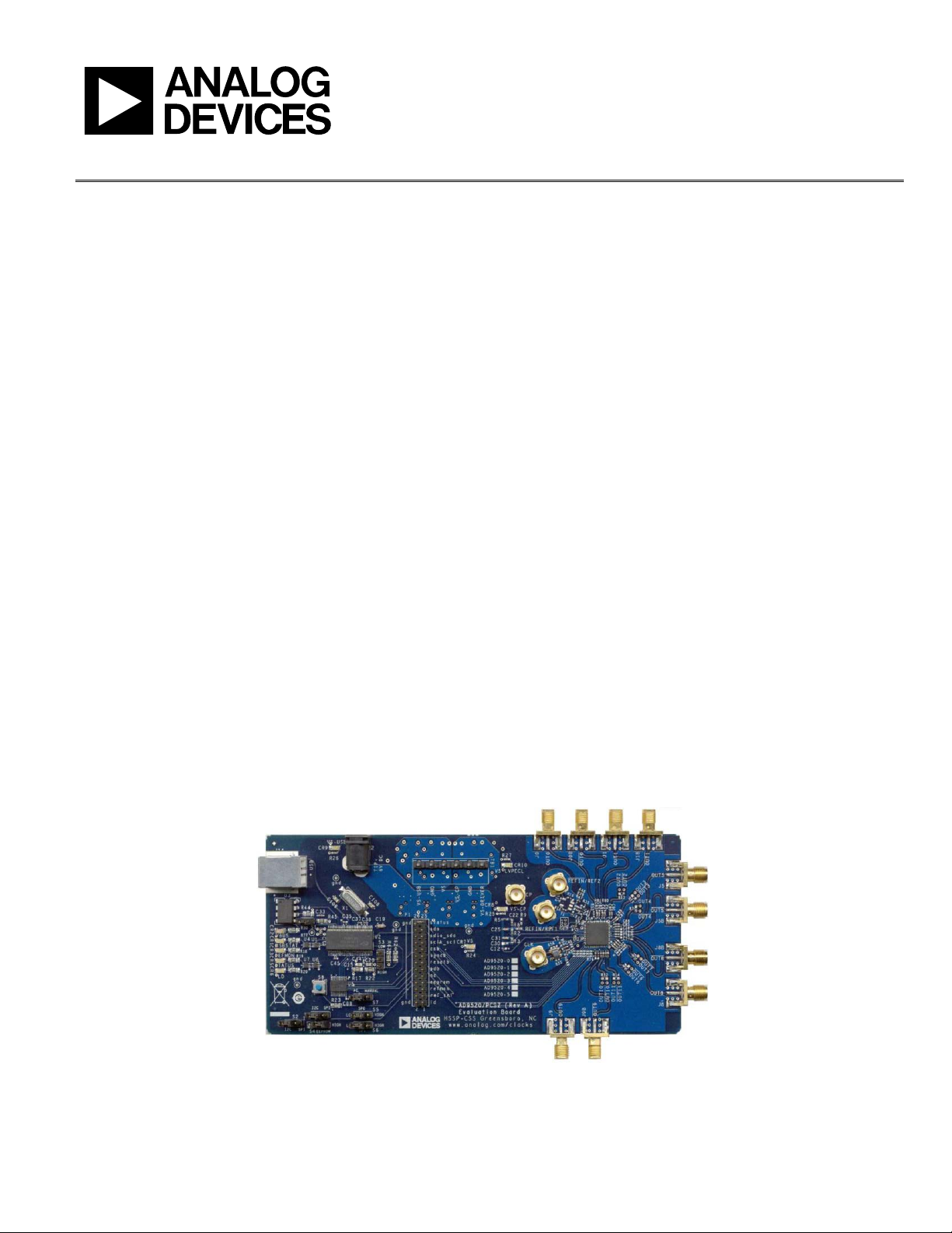
AD9520 EVALUATION BOARD
Figure 1.
See the last page for an important warning and disclaimers. Rev. 0 | Page 1 of 16
8746-001

UG-076 Evaluation Board User Guide
TABLE OF CONTENTS
Features .............................................................................................. 1
Applications ....................................................................................... 1
General Description ......................................................................... 1
AD9520 Evaluation Board ............................................................... 1
Revision History ............................................................................... 2
Evaluation Board Hardware ............................................................ 3
Power and PC Connections ........................................................ 3
Signal Connections ...................................................................... 3
Bypassing the Wall Power Supply ............................................... 3
Bypassing the PLL (Clock Distribution Only) ............................. 3
Using an External VCXO ............................................................ 3
Using I2C Serial Port Mode ......................................................... 3
Evaluation Board Software .............................................................. 4
Software Installation .................................................................... 4
Running the Software .................................................................. 4
Quick Start Guide to the AD9520 PLL .......................................... 5
Evaluation Software Components .................................................. 7
Main Window ............................................................................... 7
PLL Reference INput Window .................................................... 8
PLL Configuration Window ....................................................... 8
REFMON, STATUS, and LD Buttons ........................................ 8
Register W/R Box ......................................................................... 9
SYNC, PD (Power Down), and RESET Buttons .......................9
EEPROM Control Window .........................................................9
Reference (R) Divider Window ...................................................9
Feedback (N) Divider Window ................................................ 10
R and N Delay Window ............................................................. 10
Phase Frequency Detector (PFD) Window ............................ 10
Charge Pump Setup Window ................................................... 11
Zero Delay Window ................................................................... 11
VCO Calibration Window ........................................................ 11
Channel Divider Window ......................................................... 11
Output Driver Window ............................................................. 12
Debug Window ........................................................................... 12
Evaluation Software Menu Items.................................................. 13
Menu Bar ..................................................................................... 13
AD9520 PLL Loop Filter ............................................................... 14
Using the Evaluation Board to Program an AD9520 on a
Customer Board .............................................................................. 15
AD9520 Binary File Generation ................................................... 16
Checksum Generation ............................................................... 16
Avoiding Checksum Mismatches ............................................. 16
ESD Caution................................................................................ 16
REVISION HISTORY
1/10—Revision 0: Initial Version
Rev. 0 | Page 2 of 16

Evaluation Board User Guide UG-076
EVALUATION BOARD HARDWARE
The following instructions are for setting up the physical
connections to the AD9520 evaluation board.
When connecting the evaluation board to a PC for the first
time, the user must install the evaluation software prior to
connecting the evaluation board.
POWER AND PC CONNECTIONS
1. Install AD9520 evaluation software. Administrative
privileges are required for installation. The 64-bit versions
of Windows® are not supported.
2. Connect the wall power supply to the main power
connector labeled P2. The following five LEDs should be
on: CR1 (USBSTAT), CR7 (VS), CR8 (VS-CP), CR9
(VS_USB), and CR10 (VS_LVPECL).
3. Connect the USB cables to the evaluation board and the
computer. The red LED labeled CR2 (VBUS) on the
AD9520 evaluation board should illuminate and the CR1
(USBSTAT) LED should start blinking.
4. If the Found New Hardware Wizard window
automatically appears when the evaluation board is
connected, select Install the software automatically
and click Next.
The Found New Hardware Wizard window may appear
twice, and a system restart may be required.
Refer to the Evaluation Board Software section for details on
running the AD9520 evaluation board software.
If the USBSTAT LED is not blinking, ensure that:
• Jumpers are installed on Position S1 and on the SPI
position of S2.
• The jumper on S4 is across the center pin and the minus
symbol.
• The USB port on the PC is operational and that the USB
cable is not damaged.
SIGNAL CONNECTIONS
To connect signals, connect a signal generator to the J10 SMA
connector. By default, the reference inputs on this evaluation
board are ac-coupled and terminated 50 to ground. An
amplitude setting of 0 dBm to 6 dBm is fine.
If the user wishes to connect a signal to REF2, connect that
signal to the J13 SMA connector. DC-coupling is recommended
in applications requiring automatic hitless reference switching.
There is a possibility that the AD9520 receive buffer can chatter
when an ac-coupled clock stops toggling.
Connect an oscilloscope, spectrum analyzer, or other lab
equipment to any of the J0 to J9 SMA connectors on the right
side of the board.
OUT0 through OUT8 are ac-coupled LVPECL outputs.
OUT9 through OUT11 are dc-coupled and have no output
termination. These are intended to allow the user to evaluate
the AD9520 output driver in CMOS mode. To use OUT9
through OUT11 in LVPECL mode, replace the 0 resistors
with 0.1 µF capacitors, and install 200 pull-down resistors.
BYPASSING THE WALL POWER SUPPLY
To bypass the wall power supply, remove the following ferrite
beads (on the backside of the board) : F7, F4, F2, and F6. Next,
connect a bench power supply to TB1 on the evaluation board.
This is useful for making AD9520 power consumption
measurements.
BYPASSING THE PLL (CLOCK DISTRIBUTION ONLY)
To bypass the PLL, connect a signal generator to the SMA connector labeled CLK. By default, this connection is ac-coupled to
the CLK pin, and terminated with 50 to ground. Refer to the
Evaluation Software Components section for details on running
the AD9520 evaluation board software.
USING AN EXTERNAL VCXO
To use an external VCXO,
1. Install a 0 Ω resistor at R9 and remove R8.
2. Connect a loop filter and external VCO/VCXO input to J12.
3. Connect the external VCO/VCXO output to the J11 SMA
connector (CLK input).
USING I2C SERIAL PORT MODE
To use I2C serial port mode,
1. Move Jumper S2 to the center and left (I
2. Move Jumper W1 to the center and left (I
3. Select the desired I
Jumper S6. Note that S5 = S6 = high is reserved for
SPI mode.
4. On the evaluation software, select Configure Serial Port
from the I/O menu (see Figure 24).
5. Click Reset Serial Port, and then click Detect Current
Configuration. A dialog box appears and acknowledges
2
the I
C mode and address.
2
C address using Jumper S5 and
2
C) pins.
2
C) pins.
Rev. 0 | Page 3 of 16
UG-076 Evaluation Board User Guide
EVALUATION BOARD SOFTWARE
Use the following instructions to set up the AD9520 evaluation
board software.
SOFTWARE INSTALLATION
Do not connect the evaluation board until the software
installation is complete.
1. The latest evaluation software and documentation can be
downloaded from www.analog.com.
2. If the software was downloaded, skip to Step 3. If using the
CD, insert the AD9520 evaluation software CD. Doubleclick My Computer, and then double-click the AD9520EV
CD icon. A window opens showing the contents of the CD
divided into four sections: Datasheet, Layout, Schematic,
and Software. The file named readme.txt contains a descrip-
tion of the CD contents and may contain additional as well
as any last minute instructions or information. Doubleclick the Software folder.
3. Double-click AD9520Eval_Setup1.1.0.exe. (Note that the
website may have a newer version.) Follow the installation
instructions. The default installation location for the
evaluation software is: C:\Program Files\Analog
Devices\AD9520 Eval Software\.
RUNNING THE SOFTWARE
Power up and connect the evaluation board to the PC. See the
Evaluation Board Hardware section for details on the various
connectors on the evaluation board.
1. Double-click AD9520 Eval Software to run the AD9520
evaluation software. Depending on whether the evaluation
board was found by the software, either light blue text
appears in a pop-up window indicating that the evaluation
board was found, or red text appears indicating that the
evaluation board was not found.
2. If the evaluation board is found, click anywhere in the pop-
up window with the Evaluation Software Ready, and the
main window for the software appears. Proceed to the
Evaluation Software Components section for details about
running the software.
If the evaluation board is not found, a dialog box appears
allowing you to select which AD9520 evaluation board is
connected while the software runs in standalone mode.
Standalone mode is useful for viewing and generating
register setup files.
See the Evaluation Board Hardware section for connecting
the evaluation board. Alternatively, you can use the software
in standalone mode, and specify which version of the AD9520
will be used. The standalone mode is useful for verifying
register settings for a given PLL setup.
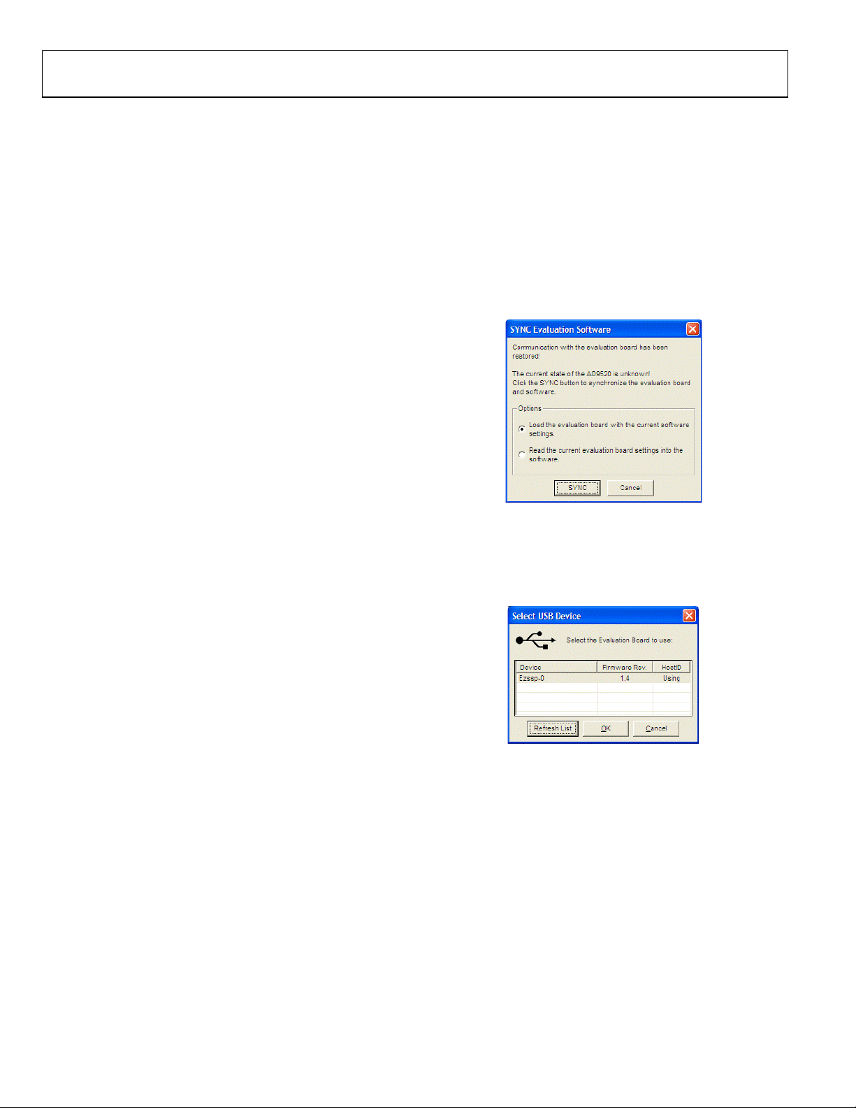
If the evaluation board is connected while the evaluation
software is running, the window in Figure 2 appears to prompt
you to load the evaluation board with the evaluation software
settings or read the evaluation board with the evaluation
software settings.
08746-002
Figure 2. SYNC Evaluation Software Window
If the evaluation board was not automatically detected when it
was connected, you can also select the Select Evaluation Board
option from the I/O menu (see Figure 24), and select Ezssp-0,
Ezssp-1, or Ezssp-2.
08746-003
Figure 3. Select USB Device Window
See the Evaluation Software Components section for a
description of the evaluation software features, or the Quick
Start Guide to the AD9520 PLL section for details on the
individual blocks of the AD9520.
Rev. 0 | Page 4 of 16
Evaluation Board User Guide UG-076
QUICK START GUIDE TO THE AD9520 PLL
When the evaluation software is installed, the evaluation board
is connected, and the software is loaded, use the following steps
to configure and lock the PLL. These steps assume that the input
signal is present, the evaluation board has not been modified,
and that the PLL loop filter is suitable for the user’s application.
This quick start guide covers only simple PLL operation to start
the PLL. See the AD9520 data sheet and Evaluation Software
Components section for a detailed explanation of the various
AD9520 features.
The following case is an example for the AD9520-4 using the
values in Tabl e 1.
Table 1.
Parameter Value
Input Frequency 19.44 MHz on REF1
Output Frequency 148.5 MHz
Reference Divider 72
Phase Detector Frequency 270 kHz
Feedback Divider 5500
VCO Frequency 1485 MHz
VCO Divider 2
Channel Divider 5
1. Turn the PLL on by selecting Normal Op from the PLL
MODE box found at the top of the main window (see
Figure 8).
2. Enter the intended reference input frequency (in
megahertz) in the REF 1 (MHz) box at the upper left
corner of the main window.
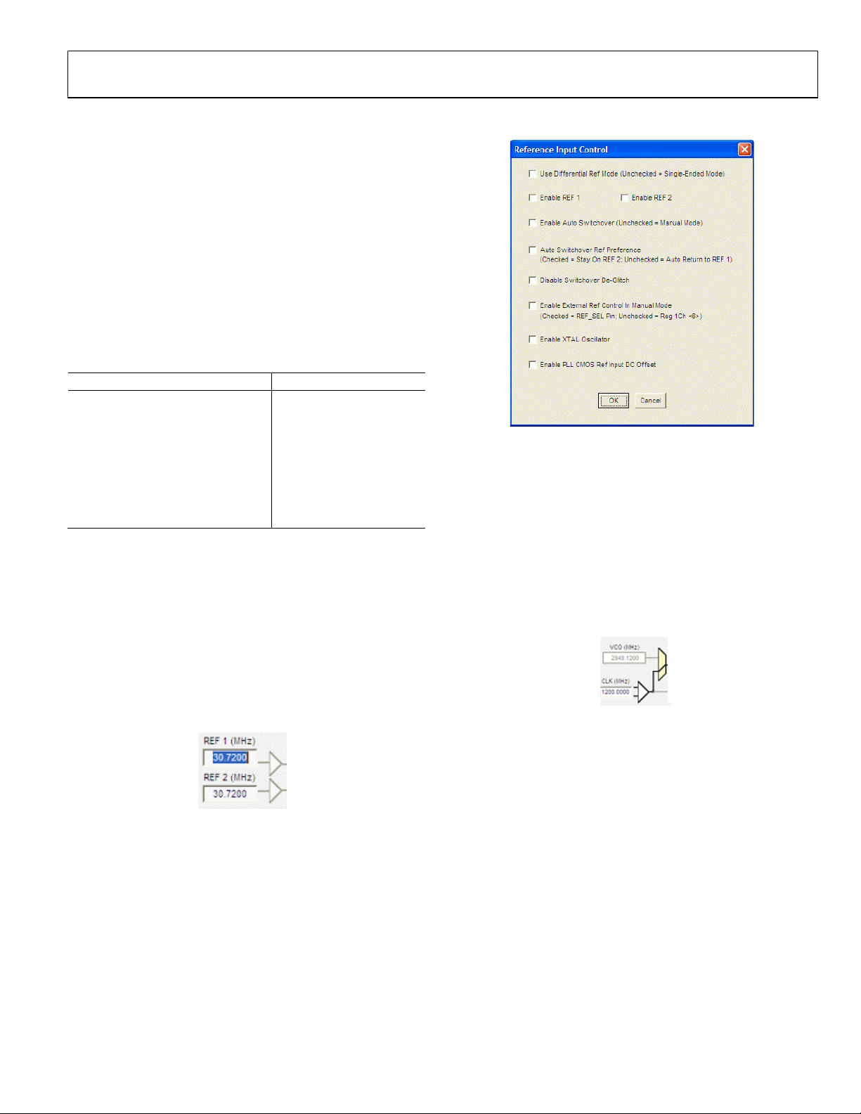
3. Click the triangular buffer symbol immediately to the
right of the input reference frequency (see Figure 4) text
boxes to load the Reference Input Control window shown
in Figure 5. Turn the REF1 reference input buffer on by
selecting the Enable REF 1 check box, and then click OK.
Figure 5. Reference Input Control Window
4. When the window closes, the WRITE button under the
REGISTER W/R section in Figure 8 blinks red. This
indicates that there are settings that have not been loaded
to the AD9520 evaluation board. Click the blinking red
WRITE button to load these settings to the evaluation
board.
5. Select the VCO as the input to the clock distribution
circuitry by clicking the mux symbol that is located
immediately to the right of the VCO (MHz) box (see
Figure 6).
08746-025
Figure 6. Buffer Symbol
When the VCO is selected, the border of the VCO (MHz)
box changes from gray to black. The current VCO
frequency is shown in the VCO (MHz) box.
08746-004
08746-024
Figure 4. Buffer Symbol
Rev. 0 | Page 5 of 16
 Loading...