

Page 1
Evaluation Board User Guide
One Technology Way • P.O. Box 9106 • Norwood, MA 02062-9106, U.S.A. • Tel: 781.329.4700 • Fax: 781.461.3113 • www.analog.com
UG-065
iMEMS ADXL345 Inertial Sensor Datalogger and Development Board
FEATURES
Ultralow power ADXL345 accelerometer
Inertial sensor development board
Datalogs onto MicroSD card
Fully programmable via serial interface; firmware examples
provided
Battery-powered for portable applications
REQUIREMENTS
2 AAA batteries
MicroSD card and card reader (for datalogging)
Computer with serial port (for programming)
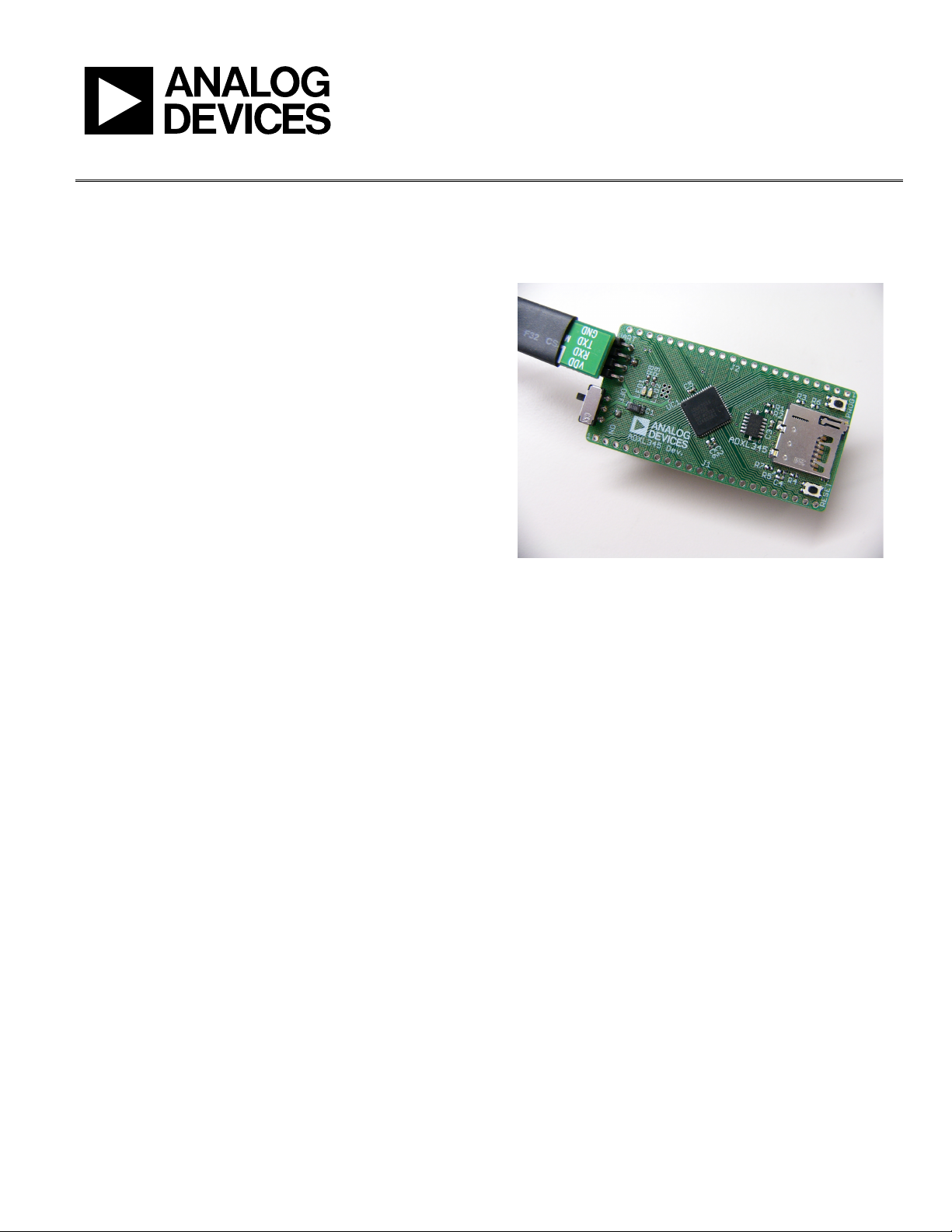
Figure 1. Inertial Sensor Development Board
08658-001
GENERAL DESCRIPTION
It is often a time saver in hardware development to make progress
on the firmware and the hardware simultaneously. The challenge is
that it proves difficult to develop firmware before the hardware
exists. The iMEMS® ADXL345 development board is an easyto-use tool that facilitates prototyping by providing a platform
that can be duplicated in the final application. Additionally, the
development board can be configured as a datalogger and can
be used to gather data for refining algorithms, tuning thresholds,
and generally familiarizing oneself with accelerometer data.
Two AAA batteries power the development board and thus it
integrates seamlessly into portable applications. Communications
and processing is done by an ARM7-based ADuC7024 microcontroller, and the interface provided is fully reprogrammable.
Moreover, all ADuC7024 pins are broken out into headers to
facilitate design of compatible expansion boards. Data is logged
onto a MicroSD memory card, providing essentially unlimited
memory capacity and operating system versatility. Data is stored in
a text file; therefore, there is no need to install any software to
operate the board or read data. Software is provided to assist
with programming the board.
Please see the last page for an importan t warning and disclai mers.
Rev. 0 | Page 1 of 8
Page 2

UG-065 Evaluation Board User Guide
TABLE OF CONTENTS
Features.............................................................................................. 1
Requirements .................................................................................... 1
General Description ......................................................................... 1
Revision History ............................................................................... 2
Overview............................................................................................ 3
Features.......................................................................................... 3
Using the Board ................................................................................ 4
REVISION HISTORY
2/10—Revision 0: Initial Revision
Getting Started...............................................................................4
Programming the Board...............................................................4
Software Tools................................................................................4
Board Layout and Schematics..........................................................6
ESD Caution...................................................................................8
Rev. 0 | Page 2 of 8
Page 3
Evaluation Board User Guide UG-065
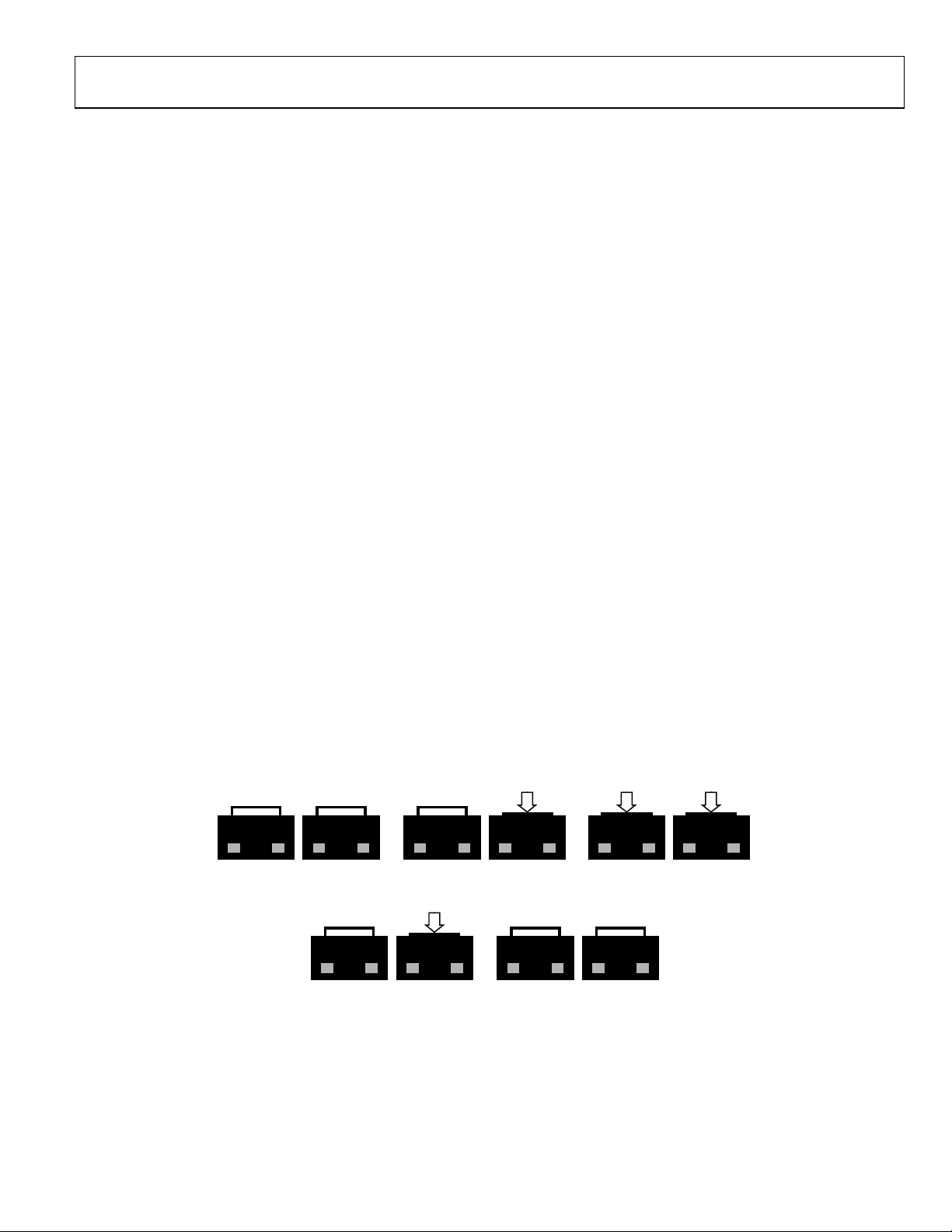
(A) RESET
AND PROG RELEASED
(B) PUSH PROG
(C) PUSH RESET
OVERVIEW
The ADXL345 inertial sensor development board has the
following features:
• A 2-layer printed circuit board (PCB), 1.125-inches × 2.25inches form factor
• A two AAA battery power supply
• A 4-pin UART header to connect to RS232 interface cable
• Reset/download push-buttons
• Power indicator/general-purpose LEDs
• Access to all microcontroller I/Os from the external
header; all device pins are brought out to the external
header pins
• Demonstration firmware
FEATURES
Power Supply
A pair of AAA batteries powers the board, and the battery
holder is located on the back of the board. An on/off switch on
the lower left of the front of the board controls power to it. The
battery voltage is not regulated but is decoupled with a 10 µF
capacitor globally, and an additional 1 µF capacitor at the device
supply pins to ground.
RS232 Interface
The ADuC7024 (UC1) P1.1 and P1.0 lines are connected to the
RS232 interface cable via the connector (UART). The interface
cable generates the required level shifting to allow direct
connection to a PC serial port. Ensure that the supplied cable
is connected to the board correctly, that is, VDD is connected to
VDD and GND is connected to GND.
RESET/PROG Push-Buttons
A RESET push-button is provided to allow the user to manually
reset the part. When inserted, the RESET pin of the ADuC7024
is pulled to GND. Because the RESET pin on the ADuC7024 is
Schmitt-triggered internally, there is no need to use an external
Schmitt trigger on this pin.
To enter serial download mode, the user must hold the P0.0/BM
pin low while reset is toggled. On the development board, serial
download mode can be easily initiated by holding down the
serial download push-button (PROG) while inserting and
releasing the reset button (RESET), as illustrated in Figure 2.
Power Indicator/General-Purpose LEDs
Two general-purpose LEDs are available on the board. A red
LED (LED1) is connected to P4.5 of the ADuC7024, and a
green LED (LED2) is connected to P4.4. Both LEDs can be
repurposed via firmware.
Breakout Header
All ADuC7024 pins are brought out to headers on either side of
the board. The headers come unpopulated but can be populated
using standard 0.1-inch header pins.
The thin form factor of the top of the board allows the design of
an expansion board to connect above the development board,
with the header pins providing both electrical and physical
connections.
Firmware
Sample firmware is provided on the ADXL345 product page.
RESET PROG
RESET PROG
Figure 2. Entering Serial Download Mode to Reprogram the Board
(D) RELEASE RESET
RESET PROG
RESET PROG
Rev. 0 | Page 3 of 8
(E) RELEASE PROG
RESET
PROG
Page 4

UG-065 Evaluation Board User Guide
USING THE BOARD
GETTING STARTED
The development board comes preprogrammed as a datalogger
at a 100 Hz datarate. To log data, do the following:
1. Insert two AAA batteries into the battery holder.
2. Insert the MicroSD card into the slot. The card should be
formatted with a FAT32 file system; most microSD cards
come this way.
3. Push the on/off switch to the on position to power up the
board. The red LED turns on, and the green LED blinks to
indicate that the board is logging data.
4. When logging is completed, slide the on/off switch to the
off position.
5. Remove the card from the slot and insert it into the card
reader.
6. Insert the card reader into the USB port on your computer.
4. In the ARMWSD window, click Browse…, see encircled in
Figure 3, and navigate to the location of the .hex file to be
loaded onto the board. Select the file and click Open.
The acceleration log file is written to the path \XL345\DB0001.txt
on the microSD card. The data in the text file consists of a set of
comma-separated t, x, y, and z values, where t corresponds to
time and x, y, and z correspond to the x-, y-, and z-axis acceleration
data for each time point. Acceleration values are logged in LSB,
where the nominal scale factor is 3.9 mg/LSB. To convert an
acceleration value from LSB to mg, simply multiply by 3.9
(nominally, or measure the sensitivity of the part for a more
accurate conversion).
To plot the logged data using Microsoft Excel, download the
XL345DB_DataPlotter.xls file from the ADXL345 product page
and follow the instructions described in the file. Users are
prompted to browse to their logged data file (DBxxxx.txt), the
data is imported and plotted in a new workbook, and users are
then prompted to save that workbook.
PROGRAMMING THE BOARD
The board can be repurposed with no programming required
using the .hex files provided on the ADXL345 product page.
The .hex files are uploaded onto the board using the ARMWSD
program, which can be downloaded at
ftp://ftp.analog.com/pub/MicroConverter/ARM%20Tools/AR
MWSDv1.8.zip. Simply unzip the folder to a known location
and open the ARMWSD.exe file to use the program. No
installation is required.
To reprogram the board, use the cable provided with the board and
follow these instructions:
1. Download the desired .hex file from the ADXL345 product
page to a known location, or locate it on your machine.
2. Open ARMWSD.
3. Click Configure… (see Figure 3) and select the Parts tab,
shown in see. Make sure the ADuC7024 is selected in the
Select Part pull-down list (see Figure 4). Additionally, in the
Comms tab, make sure the Baudrate is set to 115200, and
the Serial Port is set to COM1, and then click OK.
Rev. 0 | Page 4 of 8
08658-003
Figure 3. ARMWSD Window
Figure 4. ARMWSD Configure Window: Parts Tab
5. Connect the programming cable to the serial port on the
PC and to the 4-pin header near the on/off switch on
the board, matching up the corresponding pins.
6. In the ARMWSD window, click Start. The Status
frame then prompts users to Press Download and
pulse Reset on Hardware. Follow the illustrations in
Figure 2.
7. When download is complete, click the Reset button on
the evaluation board. The ARMWSD program can now
be closed.
08658-005
SOFTWARE TOOLS
In addition to the ready-to-upload examples provided on the
ADXL345 product page, the development board is fully modifiable
and reprogrammable to allow for easy prototyping and firmware
development. Firmware is written in C, and it is compiled for
Page 5

Evaluation Board User Guide UG-065
the ADuC7024 ARM7 processor. Software suites (Keil, IAR, and
GNU) for writing and compiling code are provided at
ftp://ftp.analog.com/pub/MicroConverter/ARM%20Tools/. The
firmware examples provided on the ADXL345 product page
were written using Keil Microvision.
For instructions on how to install and use the software, refer to
the ADuC702x MicroConverter™ GetStarted Guide at:
ftp://ftp.analog.com/pub/MicroConverter/ADuC702xV1.3/AD
uC702xGetStartedv1.3.pdf.
To reprogram the board, download the ARMWSD program at
ftp://ftp.analog.com/pub/MicroConverter/ARM%20Tools/AR
MWSDv1.8.zip.
With Keil Microvision installed, download the EVALADXL345Z-DB Files.zip file from the ADXL345 product page
Unzip this into a known directory. Navigate into the firmware
folder and open DevBoardProj.Uv2. The project opens in Keil
Microvision and allows users to modify and recompile the
program.
Rev. 0 | Page 5 of 8
Page 6
UG-065 Evaluation Board User Guide
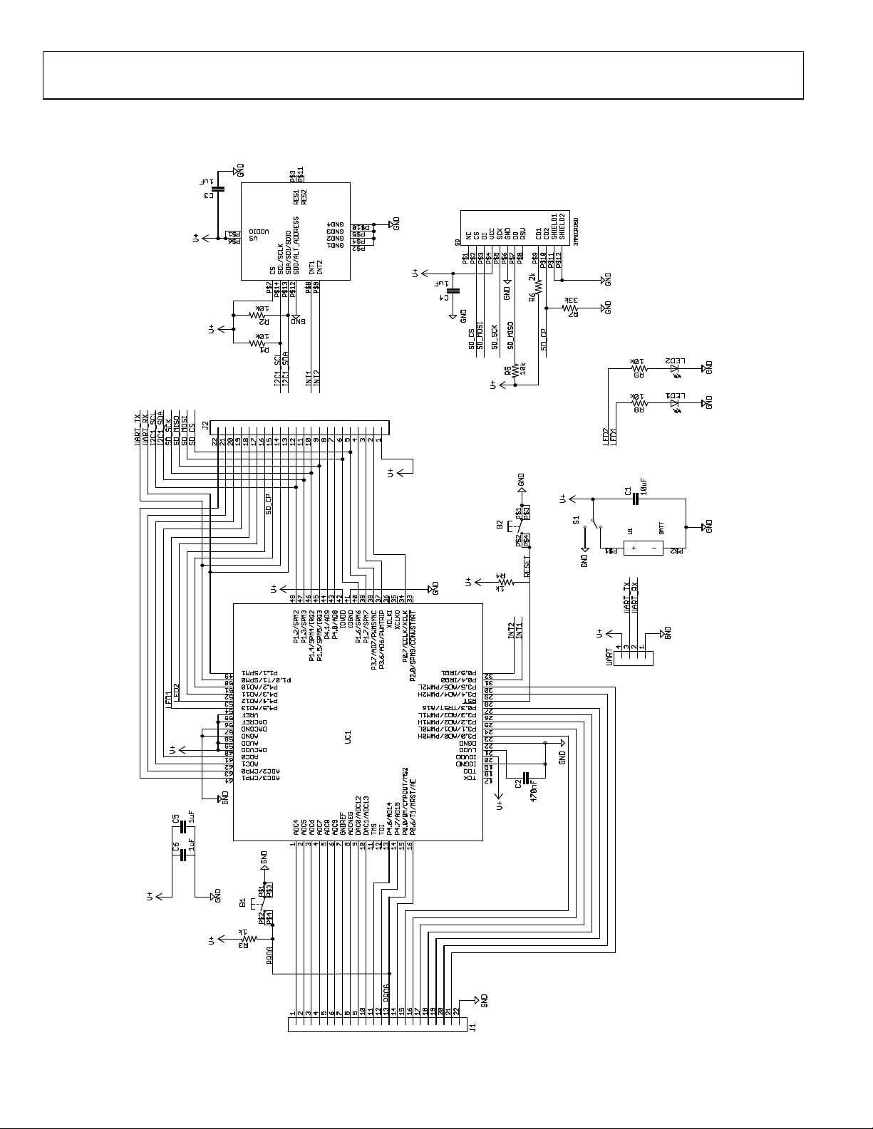
BOARD LAYOUT AND SCHEMATICS
See the ADXL345 product page for electronic versions of the layout and schematic files.
08658-004
Figure 5. ADXL345 Development Board Schematics
Rev. 0 | Page 6 of 8
Page 7
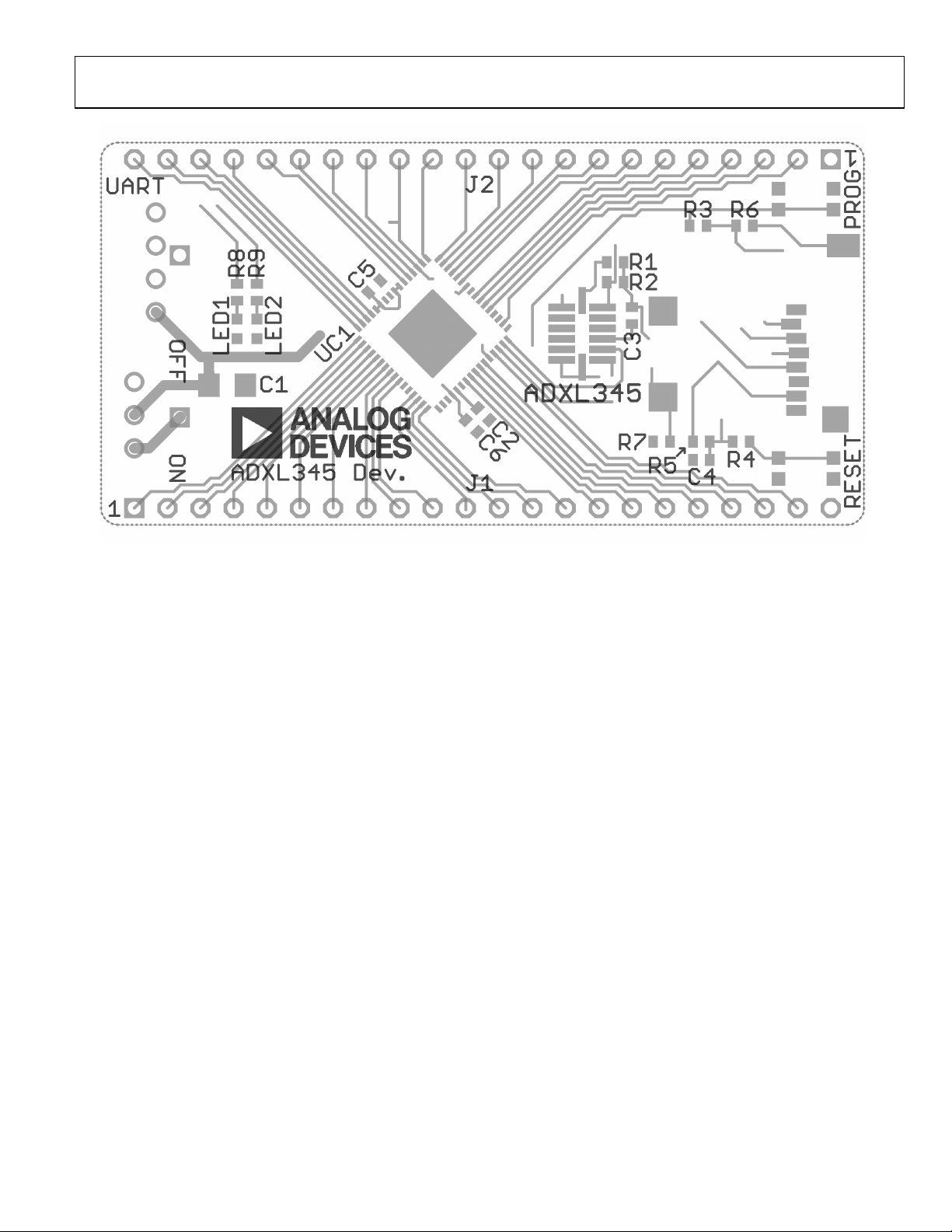
Evaluation Board User Guide UG-065
08658-003
Figure 6. ADXL345 Development Board Layout
Rev. 0 | Page 7 of 8
Page 8

UG-065 Evaluation Board User Guide
ESD CAUTION
Evaluation boards are only intended for device evaluation and not for production purpo ses. Evaluation boards ar e supplied “as is” and w ithout warranties of any kind, express,
implied, or statutory including, but not l imited to, any implied warranty of merchantability or fitness for a part icular purpose. No license is granted by implication or otherwise under
any patents or other intellectual property by application or use of evaluation boards. Information furnished by Analog Devices is believed to be accurate and re liable. However, no
responsibility is a ssumed by Analog Devices for its use, n or for any infringements of patents or other rights of third parties that may result from its use. Analog De vices re serves the
right to change devices or specifications at any time wi thout notice. Trademar ks and registered trademarks are t he property of their respective owne rs. Evaluation boards are not
authorized to be used in life support devices or systems.
©2010 Analog Devices, Inc. All rig hts reserved. Trademarks and
registered trademarks are the property of their respective owners.
UG08658-0-2/10(0)
Rev. 0 | Page 8 of 8
 Loading...