

Page 1

SHARC® USB EZ-Extender
Manual
®
Analog Devices, Inc.
One Technology Way
Norwood, Mass. 02062-9106
Revision 2.0, April 2006
Part Number
82-000197-01
a
Page 2

Copyright Information
©2006 Analog Devices, Inc., ALL RIGHTS RESERVED. This document
may not be reproduced in any form without prior, express written consent
from Analog Devices, Inc.
Printed in the USA.
Limited Warranty
The SHARC USB EZ-Extender is warranted against defects in materials
and workmanship for a period of one year from the date of purchase from
Analog Devices or from an authorized dealer.
Disclaimer
Analog Devices, Inc. reserves the right to change this product without
prior notice. Information furnished by Analog Devices is believed to be
accurate and reliable. However, no responsibility is assumed by Analog
Devices for its use; nor for any infringement of patents or other rights of
third parties which may result from its use. No license is granted by implication or otherwise under the patent rights of Analog Devices, Inc.
Trademark and Service Mark Notice
The Analog Devices logo, SHARC, VisualDSP++, EZ-KIT Lite, and
EZ-Extender are registered trademarks of Analog Devices, Inc.
All other brand and product names are trademarks or service marks of
their respective owners.
Page 3

Regulatory Compliance
The SHARC USB EZ-Extender has been certified to comply with the
essential requirements of the European EMC directive 89/336/EEC
(inclusive 93/68/EEC) and, therefore, carries the “CE” mark.
The SHARC USB EZ-Extender had been appended to Analog Devices
Development Tools Technical Construction File referenced
“DSPTOOLS1” dated December 21, 1997 and was awarded CE Certification by an appointed European Competent Body and is on file.
The EZ-KIT Lite evaluation system contains ESD
(electrostatic discharge) sensitive devices. Electrostatic charges readily accumulate on the human
body and equipment and can discharge without
detection. Permanent damage may occur on devices
subjected to high-energy discharges. Proper ESD
precautions are recommended to avoid performance
degradation or loss of functionality. Store unused
EZ-KIT Lite boards in the protective shipping
package.
Page 4

Page 5

CONTENTS
PREFACE
Product Overview ......................................................................... viii
Purpose of This Manual .................................................................. ix
Intended Audience .......................................................................... ix
Manual Contents ............................................................................ ix
What’s New in This Manual ............................................................. x
Technical or Customer Support ........................................................ x
Supported Products ......................................................................... xi
Product Information ....................................................................... xi
Related Documents ................................................................... xi
Notation Conventions .................................................................... xiv
USB EZ-EXTENDER INTERFACE
USB EZ-Extender Setup ............................................................... 1-1
USB Software Documentation ................................................. 1-2
USB 2.0 Interface ......................................................................... 1-2
USB EZ-EXTENDER HARDWARE REFERENCE
System Architecture ...................................................................... 2-1
Processor Select Jumper (JP1) ........................................................ 2-2
SHARC USB EZ-Extender Manual v
Page 6

CONTENTS
USB EZ-EXTENDER BILL OF MATERIALS
USB EZ-EXTENDER SCHEMATIC
Title Page ..................................................................................... B-1
Expansion Interface ...................................................................... B-2
Bus Switches ................................................................................. B-3
USB Interface ............................................................................... B-4
INDEX
vi SHARC USB EZ-Extender Manual
Page 7

PREFACE
Thank you for purchasing the SHARC® USB EZ-Extender®, Analog
Devices, Inc. extension board to the EZ-KIT Lite® evaluation systems for
ADSP-21262, ADSP-21364, and ADSP-21369 processors.
The SHARC processors are based on a 32-bit super Harvard architecture
that includes a unique memory architecture comprised of two large
on-chip, dual-ported SRAM blocks coupled with a sophisticated IO processor, which gives a SHARC processor the bandwidth for sustained
high-speed computations. SHARC processors represents today’s de facto
standard for floating-point processor targeted for premium audio
applications.
The EZ-KIT Lites and SHARC USB EZ-Extender are designed to be used
in conjunction with the VisualDSP++® development environment. VisualDSP++ offers a powerful programming tool with new flexibility that
significantly decreases time required to port software code to a processor,
reducing time-to-market.
To learn more about Analog Devices development software, go to
http://www.analog.com/processors/tools/.
SHARC USB EZ-Extender Manual vii
Page 8

Product Overview
Product Overview
The SHARC USB EZ-Extender is a separately sold extension board that
plugs onto the expansion interface of the ADSP-21262, ADSP-21364, or
ADSP-21369 EZ-KIT Lite evaluation system. The extension board aids
the design and prototyping phases of ADSP-21262, ADSP-21364, or
ADSP-21369 processor targeted applications.
The board extends the capabilities of the evaluation system by providing a
connection between the parallel port or asynchronous memory bus of the
SHARC processor and a USB 2.0 device.
• USB 2.0 interface
D PLX Technology’s NetChip 2272 device
D USB driver and application code
D USB logo certified
• No power supply required
D Derives power from EZ-KIT Lite
• CE certified
• Dimensions
D 3.13 in (H) x 3.6 in (W)
Before using any of the interfaces, follow the setup procedure in “USB
EZ-Extender Setup” on page 1-1.
Example programs are available to demonstrate the capabilities of the
SHARC USB EZ-Extender board.
viii SHARC USB EZ-Extender Manual
Page 9

Preface
Purpose of This Manual
The SHARC USB EZ-Extender Manual describes the operation and configuration of the components on the extension board. A schematic and a
bill of materials are provided as a reference for future SHARC processor
board designs.
Intended Audience
This manual is a user’s guide and reference to the SHARC USB
EZ-Extender. Programmers who are familiar with the Analog Devices
SHARC processor architecture, operation, and development tools are the
primary audience for this manual.
Programmers who are unfamiliar with VisualDSP++ or EZ-KIT Lite evaluation software should refer to the ADSP-21262, ADSP-21364, or
ADSP-21369 Evaluation System Manual, VisualDSP++ online Help, and
user’s or getting started guides. For the locations of these documents, refer
to “Related Documents”.
Manual Contents
The manual consists of:
• Chapter 1, “USB EZ-Extender Interface” on page 1-1
Provides basic board information.
• Chapter 2, “USB EZ-Extender Hardware Reference” on page 2-1
Provides information on the hardware aspects of the board.
• Appendix A, “USB EZ-Extender Bill Of Materials” on page A-1
Provides a list of components used to manufacture the
EZ-Extender board.
SHARC USB EZ-Extender Manual ix
Page 10

What’s New in This Manual
• Appendix B, “USB EZ-Extender Schematic” on page B-1
Provides the resources to allow EZ-KIT Lite board-level debugging
or to use as a reference design.
L
Appendix B now is part of the online Help. The PDF version of
the SHARC USB EZ-Extender Manual is located in the
Docs\EZ-KIT Lite Manuals folder on the installation CD. Alterna-
tively, the book can be found on the Analog Devices Web site:
www.analog.com/processors.
What’s New in This Manual
This edition of the SHARC USB EZ-Extender Manual has been updated
for the latest revision of VisualDSP++.
Technical or Customer Support
You can reach Analog Devices, Inc. Customer Support in the following
ways:
• Visit the Embedded Processing and DSP products Web site at
http://www.analog.com/processors/technicalSupport
• E-mail tools questions to
processor.tools.support@analog.com
• E-mail processor questions to
processor.support@analog.com (World wide support)
processor.europe@analog.com (Europe support)
processor.china@analog.com (China support)
• Phone questions to 1-800-ANALOGD
x SHARC USB EZ-Extender Manual
Page 11

• Contact your Analog Devices, Inc. local sales office or authorized
distributor
• Send questions by mail to:
Analog Devices, Inc.
One Technology Way
P.O. Box 9106
Norwood, MA 02062-9106
USA
Supported Products
The SHARC USB EZ-Extender is designed as an extension board to the
ADSP-21262, ADSP-21364, and ADSP-21369 EZ-KIT Lite evaluation
systems.
Preface
Product Information
You can obtain product information from the Analog Devices Web site,
from the product CD-ROM, or from the printed publications (manuals).
Analog Devices is online at www.analog.com. Our Web site provides information about a broad range of products—analog integrated circuits,
amplifiers, converters, and digital signal processors.
Related Documents
For information on product related development software, see the following publications.
All documentation is available online. Most documentation is available in
printed form.
SHARC USB EZ-Extender Manual xi
Page 12

Product Information
Table 1. Related Processor Publications
Title Description
ADSP-21262 SHARC Microprocessor Datasheet General functional description, pinout, and
timing of the ADSP-21262 processors
ADSP-21364 SHARC Microprocessor Datasheet General functional description, pinout, and
timing of the ADSP-21364 processors
ADSP-21369 SHARC Processor Datasheet General functional description, pinout, and
timing of the ADSP-21369 processors
ADSP-2126x SHARC DSP Core Manual
ADSP-2126x SHARC DSP Peripherals Manual
ADSP-2136x SHARC Processor Hardware Reference for the ADSP-21363/4/5/6 Processors
ADSP-2136x SHARC Processor Hardware Reference for ADSP-21367/8/9 Processors
ADSP-21160 SHARC DSP Instruction Set Reference
ADSP-2136x SHARC Processor Programming
Reference
ADSP-21262 processors: description of internal architecture and all register functions
ADSP-21364 processors: description of internal architecture and all register functions
ADSP-21369 processors: description of internal architecture and all register functions
ADSP-21262 processors: description of all
allowed assembly instructions
ADSP-21264 and ADSP-21369 processors:
description of all allowed assembly instructions
Table 2. Related VisualDSP++ Publications
Title Description
ADSP-21262 EZ-KIT Lite Evaluation System
Manual
ADSP-21364 EZ-KIT Lite Evaluation System
Manual
ADSP-21369 EZ-KIT Lite Evaluation System
Manual
VisualDSP++ User’s Guide Description of VisualDSP++ features and usage
Description of the ADSP-21262 EZ-KIT Lite
features and usage
Description of the ADSP-21364 EZ-KIT Lite
features and usage
Description of the ADSP-21369 EZ-KIT Lite
features and usage
VisualDSP++ Assembler and Preprocessor Manual
VisualDSP++ C/C++ Complier and Library
Manual for SHARC Processors
Description of the assembler function and
commands
Description of the complier function and commands for SHARC processors
xii SHARC USB EZ-Extender Manual
Page 13

Preface
Table 2. Related VisualDSP++ Publications (Cont’d)
Title Description
VisualDSP++ Linker and Utilities Manual Description of the linker function and com-
mands
VisualDSP++ Loader and Utilities Manual Description of the loader function and com-
mands
Visit the Technical Library Web site to access all processor and tools manuals and datasheets:
http://www.analog.com/processors/resources/technicalLibrary.
SHARC USB EZ-Extender Manual xiii
Page 14

Notation Conventions
Notation Conventions
Text conventions used in this manual are identified and described as
follows.
Example Description
{this | that} Alternative required items in syntax descriptions appear within curly
brackets and separated by vertical bars; read the example as this or
that. One or the other is required.
[this | that] Optional items in syntax descriptions appear within brackets and sepa-
rated by vertical bars; read the example as an optional this or that.
[this,…] Optional item lists in syntax descriptions appear within brackets
delimited by commas and terminated with an ellipse; read the example
as an optional comma-separated list of
.SECTION Commands, directives, keywords, and feature names are in text with
letter gothic font.
this.
filename Non-keyword placeholders appear in text with italic style format.
Note: For correct operation, ...
A Note provides supplementary information on a related topic. In the
L
a
[
L
xiv SHARC USB EZ-Extender Manual
Additional conventions, which apply only to specific chapters, may
appear throughout this document.
online version of this book, the word Note appears instead of this
symbol.
Caution: Incorrect device operation may result if ...
Caution: Device damage may result if ...
A Caution identifies conditions or inappropriate usage of the product
that could lead to undesirable results or product damage. In the online
version of this book, the word Caution appears instead of this symbol.
Warn in g: Injury to device users may result if ...
A Warning identifies conditions or inappropriate usage of the product
that could lead to conditions that are potentially hazardous for the
devices users. In the online version of this book, the word Wa rn in g
appears instead of this symbol.
Page 15

1 USB EZ-EXTENDER
INTERFACE
This chapter provides the setup procedures for both the SHARC USB
EZ-Extender and EZ-KIT Lite (ADSP-21262, ADSP-21364, or
ADSP-21369) and describes the USB interface the extender supports.
USB EZ-Extender Setup
It is very important to set up all of the components of the system containing the USB EZ-Extender before applying power to that system. The
following procedure is recommended for the correct setup.
Power your system when these steps are completed:
1. Read the applicable design interface section in this chapter—the
text provides an overview of the capabilities of the interface.
2. Read “System Architecture” on page 2-1 to understand the physical
connections of the extension board. For detailed information, refer
to “USB EZ-Extender Schematic” on page B-1.
3. Remove any rubber feet that may be attached to the EZ-KIT Lite.
In place of these rubber feet, install the four nylon feet and screws
provided with the USB EZ-Extender. Install the nylon feet in the
mounting holes of the EZ-KIT Lite’s printed circuit board (PCB).
Flip the EZ-KIT Lite upside down so that the three expansion
headers (
SHARC USB EZ-Extender Manual 1-1
J1–3) are facing up.
Page 16

USB 2.0 Interface
4. Set the jumper on the USB EZ-Extender board. Use the block diagram in Figure 2-1 on page 2-1 in conjunction with “Processor
Select Jumper (JP1)” on page 2-2.
5. Set the switches on the EZ-KIT Lite board. If not already, familiarize yourself with the documentation and schematics of the EZ-KIT
Lite (see “Related Documents”). Compare the expansion interface
signals of the USB EZ-Extender board with the signals of the
EZ-KIT Lite board to ensure there is no contention. For example,
it may be necessary to disable other devices connected to the expansion interface of the processor and disable the push buttons on the
EZ-KIT Lite.
6. Install the USB EZ-Extender on the EZ-KIT Lite via the
three-connector expansion interface.
USB Software Documentation
For information on the USB software (host-side and device-side), refer to
the USB Software Readme.txt file located in the
…\212xx\Examples\USB EZ-EXTENDER or
…\213xx\Examples\USB EZ-EXTENDER subdirectory of the VisualDSP++
installation directory.
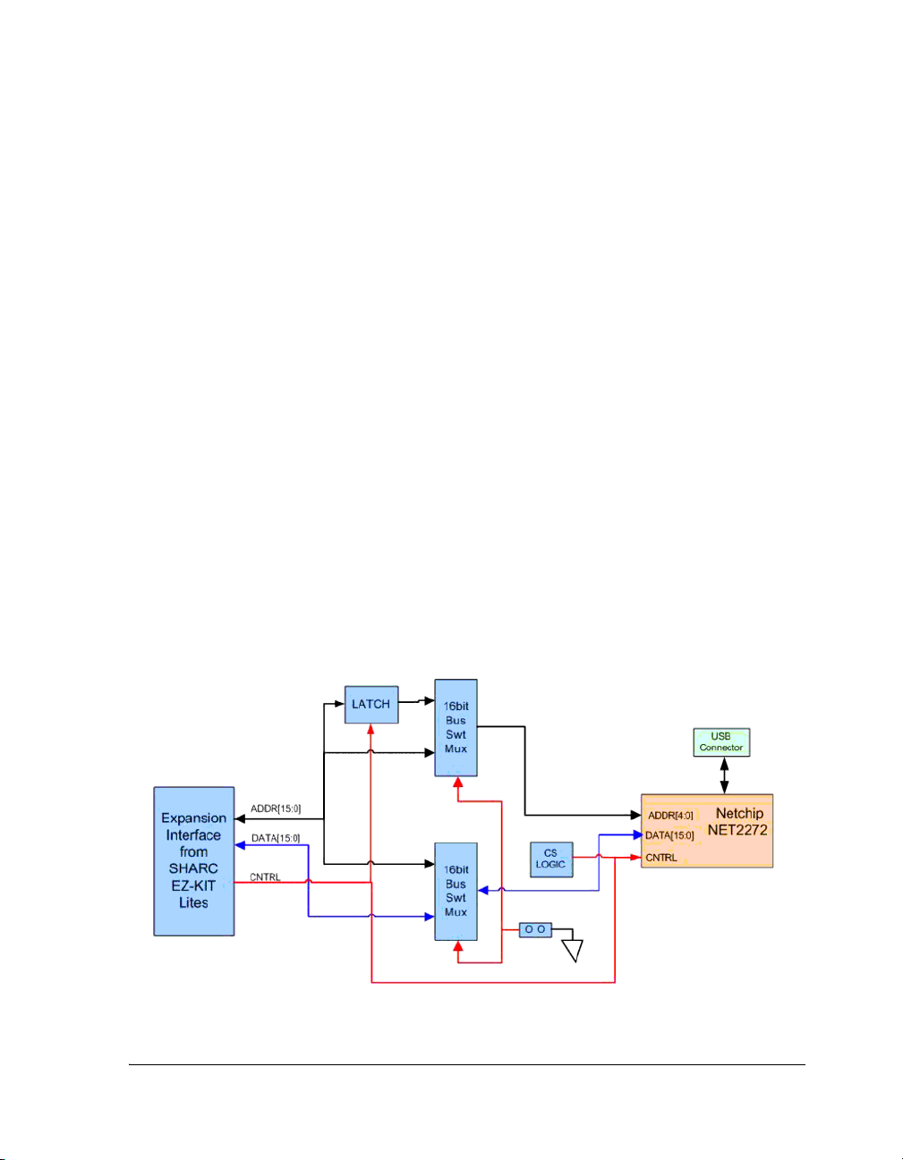
USB 2.0 Interface
The USB EZ-Extender allows you to connect a USB 2.0 chip to a SHARC
processor without any other programmable logic. PLX Technology’s
NetChip 2272 device ties directly to the parallel port or asynchronous
memory bank of the SHARC processor. You can read from and write to
the USB 2.0 controller by directly addressing the named memory bank.
1-2 SHARC USB EZ-Extender Manual
Page 17

USB EZ-Extender Interface
You can reset the NetChip 2272 device by asserting
LOW these flag pins:
• FLAG2 on the ADSP-21262 and ADSP-21364 processors
• FLAG0 on the ADSP-21369 processor
The USB interrupt request pin (IRQ) line of the extender connects to
FLAG1 on the ADSP-21262, ADSP-21364, and ADSP-21369 processors.
This flag pin may be used for push buttons or LEDs on the respective
EZ-KIT Lites; consequently, the user must make the proper changes to
that EZ-KIT Lite.
When writing to and reading from the USB device using the EZ-KIT
Lites, use memory addresses listed in Table 1-1.
Table 1-1. USB Device Memory
EZ-KIT Lite Starting Address Ending Address
ADSP-21262 0x0100 6C00 0x0100 6FE0
ADSP-21364 0x0100 6C00 0x0100 6FE0
ADSP-21369 0x0C00 0000 0x0C00 03E0
SHARC USB EZ-Extender Manual 1-3
Page 18

USB 2.0 Interface
1-4 SHARC USB EZ-Extender Manual
Page 19
2 USB EZ-EXTENDER
HARDWARE REFERENCE
This chapter describes the hardware design of the USB EZ-Extender. The
following topics are covered.
• “System Architecture” on page 2-1
Describes the extension board’s configuration.
• “Processor Select Jumper (JP1)” on page 2-2
Describes the configuration jumper’s functionality.
System Architecture
A block diagram of the SHARC USB EZ-Extender is shown in Figure 2-1.
Figure 2-1. Block Diagram
SHARC USB EZ-Extender Manual 2-1
Page 20

Processor Select Jumper (JP1)
Processor Select Jumper (JP1)
Before using the SHARC USB EZ-Extender, follow the steps in “USB
EZ-Extender Setup” on page 1-1.
Figure 2-2 shows the location of the processor select jumper JP1. A
two-pin jumper can be placed on the respective jumper header for different functionality.
Figure 2-2. JP1 Jumper Settings
2-2 SHARC USB EZ-Extender Manual
Page 21

USB EZ-Extender Hardware Reference
Table 2-1 describes the jumper settings and functionality. The jumper, by
default, must have no jumpers on any of its pins.
Table 2-1. JP1 Settings
EZ-KIT Lite JP1 Setting
ADSP-21262/ADSP-21364 No jumpers (default)
ADSP-21369 Installed
L
When using the extender with an ADSP-21262 or ADSP-21364
EZ-KIT Lite, you must not place any jumpers on JP1. Placing a
jumper on JP1 can damage the extender card and/or the EZ-KIT
Lite. When using the extender with an ADSP-21369 EZ-KIT Lite,
you must place the jumper on JP1.
SHARC USB EZ-Extender Manual 2-3
Page 22

Processor Select Jumper (JP1)
2-4 SHARC USB EZ-Extender Manual
Page 23

A USB EZ-EXTENDER BILL OF
MATERIALS
The bill of materials corresponds to “USB EZ-Extender Schematic” on
page B-1. Please check the latest schematic on the Analog Devices Web
site:
http://www.analog.com/Processors/Processors/DevelopmentTools/tec
hnicalLibrary/manuals/DevToolsIndex.html#Evaluation%20Kit%20Manuals
.
Ref. Qty. Description Reference
Designators
1 1 SN74LVC1G32
SOT23-5
2 1 SN74LVC1G08
SOT23-5
3 1 NET2272
TQFP64
4 1 PI3B16234
TSSOP56
5 1 30MHZ OSC010 Y1 ECLIPTEK E2SAA10-30.000M
6 1 PI3B16226
BQSOP40
7 1 SN74ALVCH163
73 TSSOP48
8 1 ADP3330ARTZ-2
5 SOT23-6
91USB 4PIN
CON009
U9 TI SN74LVC1G32DBVRE4
U11 TI SN74LVC1G08DBVR
U10 NET CHIP NET2272REV1A-LF
U1 PERICOM
U4 PERICOM
U2 TI SN74ALVCH16373DGGR
VR1 ANALOG
P4 MILL MAX 897-43-004-90-000
Manufacturer Part Number
PI3B16234AE
SEMI
PI3B16226BE
SEMI
G4
ADP3330ARTZ-2.5-R7
DE VICES
000
SHARC USB EZ-Extender Manual A-1
Page 24

Ref. Qty. Description Reference
Designators
Manufacturer Part Number
10 3 0.05 45x2
CON018
11 1 IDC 2X1 IDC2X1 JP1 FCI 90726-402HLF
12 2 600 100MHZ
500MA 1206
13 1 47.0K 1/10W 1%
0805
14 2 42 100MHZ 4A
0805
15 2 0.47UF 16V 10%
0805
16 3 10UF 6.3V 10%
0805
17 19 0.01UF 16V 10%
0402
18 15 10K 1/16W 5%
0402
19 2 10PF 50V 5%
0805
20 1 1.5K 1/10W 5%
0603
P1-3 SAMTEC TFC-145-32-F-D
FER3-4 STEWARD HZ1206B601R-10
R3 VISHAY CRCW080547K0FKEA
FER1-2 TAIYO
YUDEN
C10-11 AVX 0805YC474KAT2A
C14,C18,C23 AVX 080560106KAT2A
C1-4,C6-7,
C12-13,C15-17,
C19-22,C24-27
R1,R4,R10-22 VISHAY CRCW040210K0FKED
C8-9 AVX 08055A100JAT2A
R5 PANASONIC ERAV15J152V
AVX 0402YC103KAT2A
FBMJ2125HS420-T
21 2 39.0 1/10W 1%
0603
22 1 2.43K 1/10W 1%
0805
23 1 330 1/10W 5%
0603
R6-7 VISHAY CRCW-060339R0FKEA
R2 DIGI KEY 311-2.43KCRTR-ND
R9 VISHAY CRCW0603330RJNEA
A-2 SHARC USB EZ-Extender Manual
Page 25

USB EZ-Extender Bill Of Materials
Ref. Qty. Description Reference
Designators
24 1 1M 1/10W 5%
0603
25 1 GREEN-SMT
LED001
R8 VISHAY CRCW06031M00FNEA
LED1 PANASONIC LN1361CTR
Manufacturer Part Number
SHARC USB EZ-Extender Manual A-3
Page 26

A-4 SHARC USB EZ-Extender Manual
Page 27

A B C
D
1
1
2
2
SHARC USB EZ-EXTENDER
Schematic
3
ANALOG
4
DEVICES
20 Cotton Road
Nashua, NH 03063
PH: 1-800-ANALOGD
3
4
Title
SHARC USB EZ-EXTENDER
TITLE
Size Board No.
C
Date Sheet of
A B C D
4-24-2006_10:01 1 4
A0197-2005
Rev
1.1B
Page 28
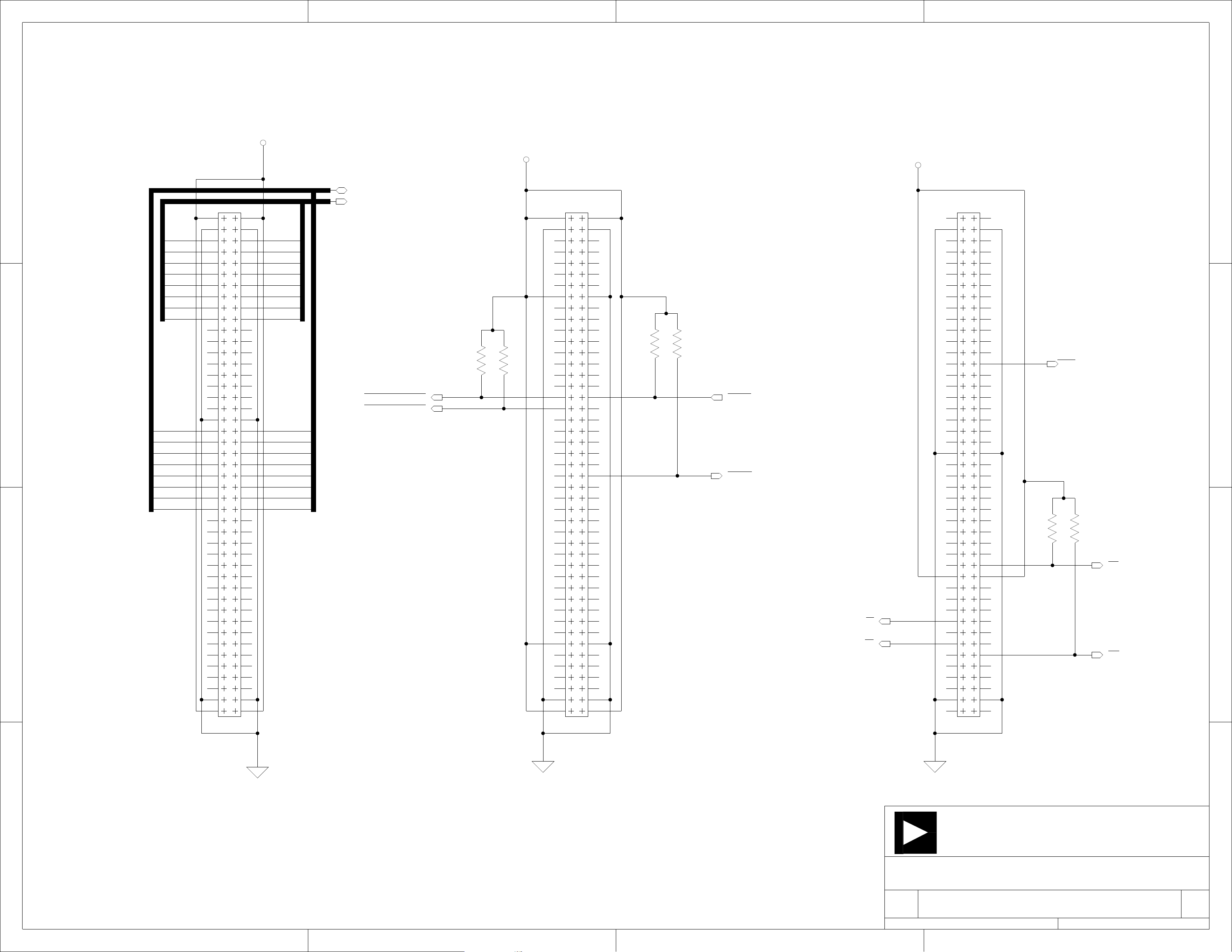
A B C
EXPANSION INTERFACE (TYPE A)
5V
D
1
DSP_D[0:15]
P1
1
3
DSP_A0
DSP_A2
DSP_A4
DSP_A6
DSP_A8
DSP_A10
DSP_A12
DSP_A14
2
DSP_D0
DSP_D2
DSP_D4
DSP_D6
DSP_D8
DSP_D10
DSP_D12
DSP_D14
3
5
7
9
11 12
13 14
15 16
17 18
19 20
21 22
23 24
25 26
27 28
29
31 32
33 34
35 36
37 38
39
41 42
43 44
45 46
47 48
49
51 52
53 54
55 56
57 58
59
61 62
63 64
65 66
67 68
69
71 72
73 74
75 76
77 78
79
81 82
83 84
85 86
87 88
89
CON018
2
4
6
8
10
30
40
50
60
70
80
90
DSP_A1
DSP_A3
DSP_A5
DSP_A7
DSP_A9
DSP_A11
DSP_A13
DSP_A15
DSP_D1
DSP_D3
DSP_D5
DSP_D7
DSP_D9
DSP_D11
DSP_D13
DSP_D15
DSP_A[0:15]
396_USB_SOFT_RESET
262_USB_SOFT_RESET
(FLAG0)
(FLAG2)
R16
10K
0402
R17
10K
0402
3.3V
P2
1
3
5
7
9
11 12
13 14
15 16
17 18
19 20
21 22
23 24
25 26
27 28
29
31 32
33 34
35 36
37 38
39
41 42
43 44
45 46
47 48
49
51 52
53 54
55 56
57 58
59
61 62
63 64
65 66
67 68
69
71 72
73 74
75 76
77 78
79
81 82
83 84
85 86
87 88
89
CON018
3.3V
P3
2
4
6
8
10
R19
R18
10K
10K
0402
0402
30
USB_IRQ
(FLAG1)
40
50
60
70
80
90
EXP_CS1
RD
WR
1
3
5
7
9
11 12
13 14
15 16
17 18
19 20
21 22
23 24
25 26
27 28
29
31 32
33 34
35 36
37 38
39
41 42
43 44
45 46
47 48
49
51 52
53 54
55 56
57 58
59
61 62
63 64
65 66
67 68
69
71 72
73 74
75 76
77 78
79
81 82
83 84
85 86
87 88
89
CON018
2
4
6
8
10
R21
10K
0402
RESET
R20
10K
0402
ALE
MS3
30
40
50
60
70
80
90
1
2
3
ANALOG
20 Cotton Road
Nashua, NH 03063
4
Title
DEVICES
SHARC USB EZ-EXTENDER
PH: 1-800-ANALOGD
4
EXPANSION INTERFACE
Size Board No.
C
Date Sheet of
A B C D
4-24-2006_10:01 2 4
A0197-2005
Rev
1.1B
Page 29

A B C
D
1
DSP_A[0:15]
ADDRESS AND DATA ARE
MULTIPLEXED ON THE 262/364
DSP_D[0:15]
2
DSP_A0
DSP_A1
DSP_A2
DSP_A3
DSP_A4
DSP_A5
DSP_A6
DSP_A7
DSP_A8
DSP_A9
DSP_A10
DSP_A11
DSP_A12
DSP_A13
DSP_A14
DSP_A15
DSP_D0
DSP_D1
DSP_D2
DSP_D3
DSP_D4
DSP_D5
DSP_D6
DSP_D7
DSP_D8
DSP_D9
DSP_D10
DSP_D11
DSP_D12
DSP_D13
DSP_D14
DSP_D15
U1
2
1B1
3
2B1
5
3B1
6
4B1
9
5B1
10
6B1
12
7B1
13
8B1
15
9B1
16
10B1
18
11B1
19
12B1
22
13B1
23
14B1
25
15B1
26
16B1
54
1B2
53
2B2
51
3B2
50
4B2
47
5B2
46
6B2
44
7B2
43
8B2
41
9B2
40
10B2
38
11B2
37
12B2
34
13B2
33
14B2
31
15B2
30
16B2
TSSOP56
1A1
2A1
3A1
4A1
5A1
6A1
7A1
8A1
9A1
10A1
11A1
12A1
13A1
14A1
15A1
16A1
SEL
PI3B16234
DSP_A0
DSP_A5
DSP_A6
DSP_A7
DSP_A8
DSP_A9
55
USB_D0
4
USB_D1
52
USB_D2
7
USB_D3
48
USB_D4
11
USB_D5
45
USB_D6
14
USB_D7
42
USB_D8
17
USB_D9
39
USB_D10
20
USB_D11
35
USB_D12
24
USB_D13
32
USB_D14
27
USB_D15
3.3V
JP1
1
2
IDC2X1
28
R1
10K
0402
USB_D[0:15]
SEL
ALE
SEL
SEL=0 FOR 262/364 (DEFAULT)
SEL=1 FOR 160/369/375
R22
10K
0402
3.3V
U2
47 2
1D1 1Q1
46 3
1D2 1Q2
44 5
1D3 1Q3
43 6
1D4 1Q4
41 8
1D5 1Q5
40 9
1D6 1Q6
38 11
1D7 1Q7
37 12
1D8 1Q8
36 13
2D1 2Q1
35 14
2D2 2Q2
33 16
2D3 2Q3
32 17
2D4 2Q4
30 19
2D5 2Q5
29 20
2D6 2Q6
27 22
2D7 2Q7
26
2D8
1
1OE
24
2OE
48
1LE
25
2LE
SN74ALVCH16373
TSSOP48
2Q8
VCC1
VCC2
VCC3
VCC4
GND1
GND2
GND3
GND4
GND5
GND6
GND7
GND8
LA0
LA5
LA6
LA7
LA8
LA9
23
7
18
31
42
4
10
15
21
28
34
39
45
3.3V
LA[0:9]
EXP_CS1
LA0
U9
1
2
SN74LVC1G32
SOT23-5
262_USB_SOFT_RESET
4
DSP_A[5:9]
396_USB_SOFT_RESET
MS3
DSP_A5
DSP_A6
DSP_A7
DSP_A8
DSP_A9
LA5
LA6
LA7
LA8
LA9
U4
39
1B1
2
2B1
36
3B1
6
4B1
33
5B1
9
6B1
30
7B1
13
8B1
26
9B1
16
10B1
23
11B1
19
12B1
38
1B2
3
2B2
35
3B2
7
4B2
32
5B2
10
6B2
29
7B2
14
8B2
25
9B2
17
10B2
22
11B2
20
12B2
BQSOP40
1A1
2A1
3A1
4A1
5A1
6A1
7A1
8A1
9A1
10A1
11A1
12A1
SEL
PI3B16226
1
37
4
34
8
31
11
28
15
24
18
21
40
USB_A0
USB_A1
USB_A2
USB_A3
USB_A4
USB_A[0:4]
USB_SOFT_RESET
USB_CS
SEL
1
2
3
3
MEMORY MAP
DEVICEMODE ADDRESS RANGEPROCESSOR OFFSET
262/364 16-bit -
0.01UF
0402
C2C1
0.01UF
0402
16-bit - NETCHIP
3.3V3.3V
C3
0402
C4
0.01UF0.01UF
0402
C27
0.01UF 0.01UF
0402
C26
0402
3.3V
0.01UF
0402
0x0C00 0000 0x0C00 03E0369/375
C7C6
0.01UF
0402
4
0x0100 6FE0 0x0020
0x0020
NETCHIP0x0100 6C00
ANALOG
20 Cotton Road
Nashua, NH 03063
DEVICES
PH: 1-800-ANALOGD
4
Title
U1 U2 U9
SHARC USB EZ-EXTENDER
BUS SWITCHES
Size Board No.
C
Date Sheet of
A B C D
4-24-2006_10:01 3 4
A0197-2005
Rev
1.1B
Page 30

A B C
D
USB_A[0:4]
1
RESET
USB_SOFT_RESET
Y1
30MHZ
OSC010
C8
10PF
0805
2
U11
1
2
SN74LVC1G08
SOT23-5
C9
10PF
0805
4
USB_VBUS
R2
2.43K
0805
USB_ALE
USB_CS
RD
WR
USB_DMARD
USB_DMAWR
USB_DACK
USB_EOT
R3
47.0K
0805
USB_A0
USB_A1
USB_A2
USB_A3
USB_A4
U10
32
LA0
31
LA1
30
LA2
29
LA3
28
LA4
58
RESET
53
ALE
61
CS
59
IOR
60
IOW
50
DMARD
34
DMAWR
51
DACK
52
EOT
18
TEST
40
TRST
17
TMC2
25
XIN
26
XOUT
13
RREF
64
VBUS
NET2272
TQFP64
USB 2.0
LD0
LD1
LD2
LD3
LD4
LD5
LD6
LD7
LD8
LD9
LD10
LD11
LD12
LD13
LD14
LD15
LCLKO
DREQ
IRQ
RSDM
DM
DP
RSDP
RPU
19
20
21
22
23
35
36
37
38
39
43
44
45
46
47
49
57
62
63
9
8
6
5
2
USB_D0
USB_D1
USB_D2
USB_D3
USB_D4
USB_D5
USB_D6
USB_D7
USB_D8
USB_D9
USB_D10
USB_D11
USB_D12
USB_D13
USB_D14
USB_D15
USB_DREQ
USB_D[0:15]
3.3V
R4
10K
0402
R7
39.0
0603
R6
39.0
0603
R5
1.5K
0603
USB_IRQ
USB_VBUS
FER1
42
0805
FER2
42
0805
R8
1M
0603
1
VCC
2
D-
3
D+
4
GND
5
SHELL
CON009
P4
C25
0.01UF
0402
3.3V
LED1
GREEN
LED001
R9
330
0603
2
6
C10
0.47UF
0805
VR1
INPUT
SD
OUTPUT
ERR
GND
4
ADP3330ARTZ-25
SOT23-6
2.5V
AVCC
1
FER3
600
1206
FER4
600
1206
AGND
2.5V5V
1
3
C11
0.47UF
0805
2
3.3V
AGND
C15
3.3V
AVCC3.3V
3
2.5V
U10
1
VDDC1
48
VDDC2
3
VDD25
15
AVDD
11
PVDD
27
VDDIO1
42
VDDIO2
55
VDDIO3
7
VDD33
NET2272
TQFP64
USB 2.0
VSSC1
VSSC2
VSSIO1
VSSIO2
VSSIO3
GND1
GND2
AVSS1
AVSS2
COM
R10
10K
24
56
33
41
54
4
10
12
14
16
USB_DMARD
USB_DMAWR
USB_ALE
USB_DACK
USB_EOT
USB_DREQ
0402
R12
10K
0402
R11
10K
0402
R13
0402
10K10K
0402
R15R14
10K
0402
0.01UF
0402
2.5V
C18
10UF
0805
C14
10UF
0805
AVCC
AGND
C17
0.01UF0.01UF
0402
C13
0.01UF
0402
C16
0402
U10 U10
C12
0.01UF
0402
C19
0.01UF
0402
0.01UF
0402
3.3V
C21
0.01UF
0402
C24
0.01UF
0402
C22C20
0.01UF
0402
C23
10UF
0805
3
U10 U11
AGND
ANALOG
20 Cotton Road
Nashua, NH 03063
4
Title
DEVICES
SHARC USB EZ-EXTENDER
PH: 1-800-ANALOGD
4
USB INTERFACE
Size Board No.
C
A0197-2005
Date Sheet of
A B C D
Rev
1.1B
444-24-2006_10:01
Page 31

IINDEX
A
architecture, of this EZ-Extender, 2-1
B
bill of materials, A-1
board schematic, B-1
C
connectors, J1-3 (expansion), 1-1
customer support, -x
D
dimensions, of this EZ-Extender, -viii
E
expansion interface, 1-1, 1-2
F
FLAG0 (USB reset) pin, ADSP-21369
processors, 1-3
FLAG1 (USB IRQ) pin, ADSP-21262/364/369
processors, 1-3
FLAG2 (USB reset) pin, ADSP-21262/364
processors, 1-3
J
JP1 (processor select) jumper, 1-2, 2-2
N
notation conventions, -xiv
P
parallel port, ADSP-21262/364/369 processors,
1-2
printed circuit boards (PCBs), 1-1
processor select jumper (JP1), 1-2, 2-2
product overview, -viii
S
schematic, of this EZ-Extender B-1
setup procedure, of this EZ-Extender, 1-1
system architecture, 2-1
U
USB
controller, 1-2
device memory map, 1-3
documentation, 1-2
IRQ line, 1-3
reset, 1-3
I
interrupt request line (IRQ), 1-3
SHARC USB EZ-Extender Manual I-1
Page 32

INDEX
I-2 SHARC USB EZ-Extender Manual
 Loading...