

Page 1
LT1076-5
5V Step-Down
Switching Regulator
FEATURES
n
Fixed 5V Output
n
2A On-Board Switch
n
100kHz Switching Frequency
n
2% Output Voltage Tolerance Over Temperature
n
Greatly Improved Dynamic Behavior
n
Available in Low Cost 5- and 7-Lead Packages
n
Only 9.5mA Quiescent Current
n
Operates Up to 60V Input
APPLICATIONS
n
5V Output Buck Converter
n
Tapped Inductor Buck Converter with 4A Output at
5V
n
Positive-to-Negative Converter
DESCRIPTION
The LT®1076-5 is a 2A fi xed 5V output monolithic bipolar
switching regulator which requires only a few external parts
for normal operation. The power switch, all oscillator and
control circuitry, all current limit components, and an output
monitor are included on the chip. The topology is a classic
positive “buck” confi guration but several design innovations allow this device to be used as a positive-to-negative
converter, a negative boost converter, and as a fl yback converter. The switch output is specifi ed to swing 40V below
ground, allowing the LT1076-5 to drive a tapped inductor
in the buck mode with output currents up to 4A.
The LT1076-5 uses a true analog multiplier in the feedback
loop. This makes the device respond nearly instantaneously
to input voltage fl uctuations and makes loop gain independent of input voltage. As a result, dynamic behavior of the
regulator is signifi cantly improved over previous designs.
On-chip pulse by pulse current limiting makes the LT10765 nearly bust-proof for output overloads or shorts. The
input voltage range as a buck converter is 8V to 60V, but
a self-boot feature allows input voltages as low as 5V in
the inverting and boost confi gurations.
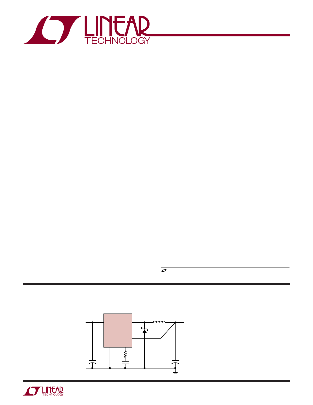
TYPICAL APPLICATION
8V TO 40V
+ +
C3
200μF
V
GND
IN
LT1076-5
The LT1076-5 is available in a low cost 5- and 7-lead TO220 packages with frequency pre-set at 100kHz and current
limit at 2.6A. See Application Note 44 for design details.
, LT, LTC and LTM are registered trademarks of Linear Technology Corporation.
All other trademarks are the property of their respective owners.
Basic Positive Buck Converter
†
V
SENSE
V
C
SW
R3
1.5k
C2
0.033μF
100μH**
MBR340*
C1
500μF
25V
LT1076-5 TA01
5V
≤1.8A
MBR330P MAY BE USED
*
≤ 25V
FOR V
IN
COILTRONICS #100-1-52
**
HURRICANE #HL-AG210LL
†
VALUE MAY BE REDUCED TO 50μH
FOR OUTPUT LOADS BELOW 1.5A
10765fc
1
Page 2
LT1076-5
ABSOLUTE MAXIMUM RATINGS
Input Voltage
LT1076-5 .............................................................45V
LT1076HV-5 .........................................................64V
Switch Voltage with Respect to Input Voltage
LT1076-5 ..............................................................64V
LT1076HV-5 .........................................................75V
Switch Voltage with Respect to Ground Pin
Negative)
(V
SW
LT1076-5 (Note 6) ................................................35V
(Note 1)
Sense Pin Voltage ............................................ –2V, 10V
Maximum Operating Ambient Temperature Range
LT1076C-5, LT1076HVC-5 ....................... 0°C to 70°C
LT1076I-5, LT1076HVI-5 ..................... –40°C to 85°C
Maximum Operating Junction Temperature Range
LT1076C-5, LT1076HVC-5 ..................... 0°C to 125°C
LT1076I-5, LT1076HVI-5 ................... –40°C to 125°C
Maximum Storage Temperature ............ –65°C to 150°C
Lead Temperature (Soldering, 10 sec) ..................300°C
LT1076HV-5 (Note 6) ...........................................45V
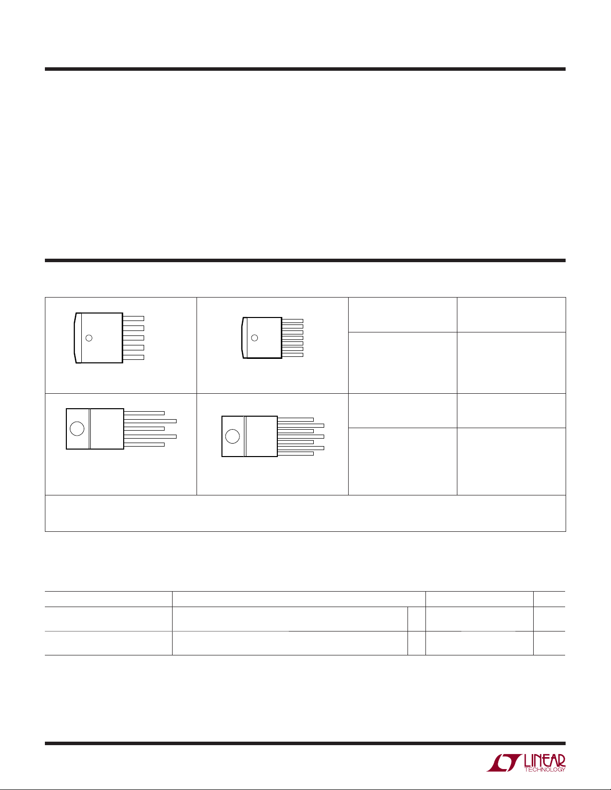
PACKAGE/ORDER INFORMATION
FRONT VIEW
5
V
IN
V
4
3
2
1
Q PACKAGE
5-LEAD PLASTIC DD
= 4°C/W, θJA = 30°C/W
θ
JC
FRONT VIEW
TAB
IS
GND
T PACKAGE
5-LEAD PLASTIC TO-220
LEADS ARE FORMED STANDARD
FOR STRAIGHT LEADS, ORDER FLOW 06
= 4°C/W, θJA = 50°C/W
θ
JC
SW
GND
V
C
FB/SENSE
5
4
3
2
1
V
IN
GND
SENSE
TAB IS
V
SW
TAB
V
C
GND
IS
FRONT VIEW
7
6
5
GND
θJC = 4°C/W, θJA = 30°C/W
7-LEAD PLASTIC TO-220
θJC = 4°C/W, θJA = 50°C/W
4
3
2
1
R PACKAGE
7-LEAD PLASTIC DD
FRONT VIEW
7
6
5
4
3
2
1
T7 PACKAGE
SHDN
V
C
SENSE
GND
I
LIM
V
SW
V
IN
SHDN
SENSE
I
LIM
V
IN
V
GND
V
C
SW
Order Options Tape and Reel: Add #TR
Lead Free: Add #PBF Lead Free Tape and Reel: Add #TRPBF
Lead Free Part Marking: http://www.linear.com/leadfree/
Consult LTC Marketing for parts specifi ed with wider operating temperature ranges. *The temperature grade is identifi ed by a label on the shipping container.
ORDER PART
NUMBER
ORDER PART
NUMBER
LT1076CQ-5 LT1076CR-5
ORDER PART
NUMBER
LT1076CT-5
ORDER PART
NUMBER
LT1076CT7-5
LT1076HVCT-5
LT1076IT-5
LT1076HVIT-5
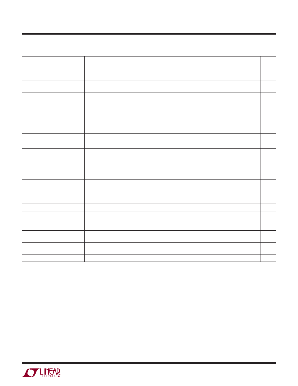
ELECTRICAL CHARACTERISTICS
The l denotes the specifi cations which apply over the full operating
temperature range, otherwise specifi cations are at TJ = 25°C. VIN = 25V, unless otherwise noted.
SYMBOL CONDITIONS MIN TYP MAX UNITS
Switch “On” Voltage (Note 2) I
Switch “Off” Leakage V
= 0.5A
SW
I
= 2A
SW
= 25V, VSW = 0
IN
V
= 25V, VSW = 0
IN
l
l
1.2
1.7
150
250
μA
μA
10765fc
2
V
V
Page 3
LT1076-5
ELECTRICAL CHARACTERISTICS
The l denotes the specifi cations which apply over the full operating
temperature range, otherwise specifi cations are at T
SYMBOL CONDITIONS MIN TYP MAX UNITS
Supply Current (Note 3) V
Minimum Supply Voltage Normal Mode
Switch Current Limit (Note 5) I
Maximum Duty Cycle
Switching Frequency
Switching Frequency Line Regulation 8V ≤ V
Error Amplifi er Voltage Gain (Note 8) 1V ≤ V
Error Amplifi er Transconductance
(Note 8)
Error Amplifi er Source and Sink
Current
Sense Pin Divider Resistance 358 kΩ
Sense Voltage V
Output Voltage Tolerance V
Output Voltage Line Regulation 8V ≤ VIN ≤ V
VC Voltage at 0% Duty Cycle
Multiplier Reference Voltage 24 V
Shutdown Pin Current V
Shutdown Thresholds Switch Duty Cycle = 0
Thermal Resistance Junction to Case 4°C/W
= 5.5V, VIN ≤ 40V
OUT
40V < V
V
< 60V
IN
= 0.1V (Device Shutdown) (Note 9)
SHDN
Start-Up Mode (Note 4)
= Open
LIM
R
= 10k (Note 10)
LIM
R
= 7k (Note 10)
LIM
TJ ≤ 125°C
V
= V
OUT
SENSE
≤ V
IN
MAX
≤ 4V 2000 V/V
C
Source (V
Sink (V
SENSE
SENSE
= 2V
C
(Nominal) = 5V
OUT
= 5.5V)
All Conditions of Input Voltage, Output Voltage,
Temperature and Load Current
MAX
Over Temperature
= 5V
SHDN
V
≤ V
SHDN
THRESHOLD
Fully Shut Down
= 25°C. VIN = 25V, unless otherwise noted.
J
= 0V (Note 5)
(Note 8)
= 4.5V)
(Note 7)
(≅ 2.5V)
l
l
l
l
l
2 2.6
8.5
9.0
140
7.3
3.5
11
12
300
8.0
4.8
3.2 A
1.8
1.2
l
85 90 %
90
l
85
100
110
120
20
l
0.03 0.1 %/V
3700 5000 8000 μmho
100
0.7
l
4.85 5 5.15 V
l
l
140
1.0
±0.5
±1.0
225
1.6
±2
±3
0.005 0.02 %/V
1.5
l
–4.0
5102050μA
2.2
0.1
2.45
0.30
2.7
0.5
mA
mA
μA
V
V
A
A
kHz
kHz
kHz
μA
mA
%
%
V
mV/°C
μA
V
V
Note 1: Stresses beyond those listed under Absolute Maximum Ratings
may cause permanent damage to the device. Exposure to any Absolute
Maximum Rating condition for extended periods may affect device
reliability and lifetime.
Note 2: To calculate maximum switch “on” voltage at currents between
low and high conditions, a linear interpolation may be used.
Note 3: A sense pin voltage (V
) of 5.5V forces the VC pin to its low
SENSE
clamp level and the switch duty cycle to zero. This approximates the zero
load condition where duty cycle approaches zero.
Note 4: Total voltage from V
up for proper regulation. For T
pin to ground pin must be ≥ 8V after start-
IN
< 25°C, limit = 5V.
A
Note 5: Switch frequency is internally scaled down when the sense pin
voltage is less than 2.6V to avoid extremely short switch on times. During
current limit testing, V
is adjusted to give a minimum switch on time
SENSE
of 1ms.
Note 6: Switch to input voltage limitation must also be observed.
Note 7: V
= 40V for the LT1076-5 and 60V for the LT1076HV-5.
MAX
Note 8: Error amplifi er voltage gain and transconductance are
specifi ed relative to the internal feedback node. To calculate gain and
transconductance from the Sense pin (Output) to the V
pin, multiply by
C
0.44.
Note 9: Does not include switch leakage.
Rk
− 1
LIM
I
≈
Note 10:
LIM
k
5
10765fc
3
Page 4

LT1076-5
PACKAGE DESCRIPTION
Q Package
5-Lead Plastic DD Pak
(Reference LTC DWG # 05-08-1461)
.256
(6.502)
.060
(1.524)
.300
(7.620)
BOTTOM VIEW OF DD PAK
HATCHED AREA IS SOLDER PLATED
COPPER HEAT SINK
.060
(1.524)
.075
(1.905)
.183
(4.648)
.060
(1.524)
TYP
.330 – .370
(8.382 – 9.398)
+.012
.143
–.020
+0.305
3.632
()
–0.508
.420
.350
.028 – .038
(0.711 – 0.965)
.565
(9.906 – 10.541)
TYP
.080
.390 – .415
° TYP
15
.067
(1.702)
BSC
.205
.165 – .180
(4.191 – 4.572)
.420
.276
.059
(1.499)
TYP
.013 – .023
(0.330 – 0.584)
.325
.045 – .055
(1.143 – 1.397)
+.008
.004
–.004
+0.203
0.102
()
–0.102
.095 – .115
(2.413 – 2.921)
.050 ± .012
(1.270 ± 0.305)
Q(DD5) 0502
.565
4
.067
RECOMMENDED SOLDER PAD LAYOUT
NOTE:
1. DIMENSIONS IN INCH/(MILLIMETER)
2. DRAWING NOT TO SCALE
.042
.090
.320
.090
.067
RECOMMENDED SOLDER PAD LAYOUT
FOR THICKER SOLDER PASTE APPLICATIONS
.042
10765fc
Page 5

R Package
7-Lead Plastic DD Pak
(Reference LTC DWG # 05-08-1462)
LT1076-5
.256
(6.502)
.060
(1.524)
.300
(7.620)
BOTTOM VIEW OF DD PAK
HATCHED AREA IS SOLDER PLATED
COPPER HEAT SINK
(1.524)
(1.905)
.060
.075
.183
(4.648)
.060
(1.524)
TYP
.330 – .370
(8.382 – 9.398)
+.012
.143
–.020
+0.305
3.632
()
–0.508
.420
.350
.565
.026 – .035
(0.660 – 0.889)
.080
TYP
.205
.390 – .415
(9.906 – 10.541)
° TYP
15
.050
(1.27)
BSC
.420
.276
.165 – .180
(4.191 – 4.572)
.059
(1.499)
TYP
.013 – .023
(0.330 – 0.584)
.325
.565
.045 – .055
(1.143 – 1.397)
+.008
.004
–.004
+0.203
0.102
()
–0.102
.095 – .115
(2.413 – 2.921)
.050 ± .012
(1.270 ± 0.305)
R (DD7) 0502
.050
RECOMMENDED SOLDER PAD LAYOUT
NOTE:
1. DIMENSIONS IN INCH/(MILLIMETER)
2. DRAWING NOT TO SCALE
.090
.035
.320
.090
.035.050
RECOMMENDED SOLDER PAD LAYOUT
FOR THICKER SOLDER PASTE APPLICATIONS
10765fc
5
Page 6

LT1076-5
PACKAGE DESCRIPTION
T Package
5-Lead Plastic TO-220 (Standard)
(Reference LTC DWG # 05-08-1421)
.390 – .415
(9.906 – 10.541)
.460 – .500
(11.684 – 12.700)
.067
BSC
(1.70)
(3.734 – 3.937)
.230 – .270
(5.842 – 6.858)
.330 – .370
(8.382 – 9.398)
.028 – .038
(0.711 – 0.965)
.147 – .155
DIA
.570 – .620
(14.478 – 15.748)
SEATING PLANE
.260 – .320
(6.60 – 8.13)
.700 – .728
(17.78 – 18.491)
.152 – .202
(3.861 – 5.131)
(3.429 – 4.191)
.165 – .180
(4.191 – 4.572)
.135 – .165
.620
(15.75)
TYP
.045 – .055
(1.143 – 1.397)
.095 – .115
(2.413 – 2.921)
.155 – .195*
(3.937 – 4.953)
.013 – .023
(0.330 – 0.584)
* MEASURED AT THE SEATING PLANE
T5 (TO-220) 0801
6
10765fc
Page 7

PACKAGE DESCRIPTION
LT1076-5
T7 Package
7-Lead Plastic TO-220 (Standard)
(Reference LTC DWG # 05-08-1422)
.390 – .415
(9.906 – 10.541)
.460 – .500
(11.684 – 12.700)
.050
BSC
(1.27)
.147 – .155
(3.734 – 3.937)
.230 – .270
(5.842 – 6.858)
.330 – .370
(8.382 – 9.398)
.026 – .036
(0.660 – 0.914)
DIA
.570 – .620
(14.478 – 15.748)
.260 – .320
(6.604 – 8.128)
SEATING PLANE
.152 – .202
(3.860 – 5.130)
.165 – .180
(4.191 – 4.572)
.700 – .728
(17.780 – 18.491)
.135 – .165
(3.429 – 4.191)
.620
(15.75)
TYP
.045 – .055
(1.143 – 1.397)
.095 – .115
(2.413 – 2.921)
.155 – .195*
(3.937 – 4.953)
.013 – .023
(0.330 – 0.584)
*MEASURED AT THE SEATING PLANE
T7 (TO-220) 0801
Information furnished by Linear Technology Corporation is believed to be accurate and reliable.
However, no responsibility is assumed for its use. Linear Technology Corporation makes no representation that the interconnection of its circuits as described herein will not infringe on existing patent rights.
10765fc
7
Page 8

LT1076-5
RELATED PARTS
PART NUMBER DESCRIPTION COMMENTS
LT1074/HV 4.4A (I
Step-Down DC/DC Converter
LT3430 60V, 2.75A (I
Step-Down DC/DC Converter
LT1956 60V, 1.2A (I
Step-Down DC/DC Converter
), 100kHz High Effi ciency
OUT
), 200kHz High Effi ciency
OUT
), 500kHz High Effi ciency
OUT
VIN: 7.3V to 45V/64V, V
VIN: 5.5V to 60V, V
VIN: 5.5V to 60V, V
OUT(MIN)
: 1.20V, IQ: 2.5mA, I
OUT(MIN)
: 1.20V, IQ: 2.5mA, I
OUT(MIN)
: 2.21V, IQ: 8.5mA, I
SHDN
SHDN
: 10μA, DD5/7, TO-2205/7
SHDN
: 25μA, TSSOP16E
: 25μA, TSSOP16E
8
Linear Technology Corporation
1630 McCarthy Blvd., Milpitas, CA 95035-7417
(408) 432-1900 ● FAX: (408) 434-0507
●
www.linear.com
10765fc
LT 0407 REV C • PRINTED IN USA
© LINEAR TECHNOLOGY CORPORATION 1994
 Loading...