

Page 1

Engineer To Engineer Note EE-89
Technical Notes on using Analog Devices’ DSP components and development tools
Phone: (800) ANALOG-D, FAX: (781) 461-3010, EMAIL: dsp.support@analog.com, FTP: ftp.analog.com, WEB: www.analog.com/dsp
Copyright 1999, Analog Devices, Inc. All rights reserved. Analog Devices assumes no responsibility for customer product design or the use or application of customers’ products
or for any infringements of patents or rights of others which may result from Analog Devices assistance. All trademarks and logos are property of their respective holders.
Information furnished by Analog Devices Applications and Development Tools Engineers is believed to be accurate and reliable, however no responsibility is assumed by Analog
Devices regarding the technical accuracy of the content provided in all Analog Devices’ Engineer-to-Engineer Notes.
Implementing A Software UART On The
ADSP-2181 EZ-KIT-LITE
a
Page 2

EE-89 Page 2
Technical Notes on using Analog Devices’ DSP components and development tools
Phone: (800) ANALOG-D, FAX: (781) 461-3010, FTP: ftp.analog.com, EMAIL: dsp.support@analog.com
Page 3

Table Of Contents Page Number
1. INTRODUCTION 3
2. BACKGROUND 3
2.1 Serial Communication 3
2.2 Asynchronous Serial Communication 3
2.3 Universal Asynchronous Receiver/Transmitter 4
3. HARDWARE 5
4. SOFTWARE 6
4.1 Data Format 6
4.2 Program Flow 6
4.3 Automatic Baud Rate Detection Routine 8
4.4 Initialization Routine 13
4.5 Bit Processing Time Interrupt Service Routine 13
4.6 Transmit Routine 14
5. EXAMPLE PROGRAM 21
5.1 Introduction 21
5.2 Program Files 21
5.3 The Main Routine 21
EE-89 Page 3
Technical Notes on using Analog Devices’ DSP components and development tools
Phone: (800) ANALOG-D, FAX: (781) 461-3010, FTP: ftp.analog.com, EMAIL: dsp.support@analog.com
Page 4

1. INTRODUCTION
This document describes a software implementation of a Universal Asynchronous Receiver Transmitter
(UART). The UART is implemented as a program running on the ADSP-2181 EZ Kit Lite. This document
will also provide basic background on serial and asynchronous transmission.
2. BACKGROUND
2.1 Serial Communication
Digital data are transmitted along paths that may physically consist of wires, radio waves, microwaves.
Such paths are often referred to as data buses. The digital data that are carried on such buses are encoded in a
digital format such as BCD, ASCII, or 8-bit words.
When data are transmitted serially, only one data path is required since the data are sent one bit at a
time. Cabling costs are lower than other methods of communication since serial communication requires the
minimum amount of wires. Serial transmission methods are characterized by how many bits per second they
can transmit. This unit of measurement is call a baud (1 bit/s). Common baud rates in serial systems are 110,
300, 600, 1200, 2400, 4800, 9600 and 19200.
2.2 Asynchronous Serial Communication
Most serial interfacing is done in an asynchronous manner. In this method, the transmitter sends a
character whenever one is available. And there is no synchronization clock pulse between the transmitter and
receiver to control the start of a character. This method is relatively slow since it requires a handshake for each
character of data transfer. In serial asynchronous systems, however, handshaking is performed by using a start
bit and one or two stop bits at the beginning and end of each character that is transmitted (As shown in Figure
1). The start bit is a logic low and the stop bit is a logic high. A parity bit is sometime added after the end of
the data bits for the receiver to detect transmission error. The number of such start, stop, and parity bits must
be agreed upon by both the transmitter and receiver.
EE-89 Page 4
Technical Notes on using Analog Devices’ DSP components and development tools
Phone: (800) ANALOG-D, FAX: (781) 461-3010, FTP: ftp.analog.com, EMAIL: dsp.support@analog.com
Page 5

Start <-------------------- Data Bits -------------------> Parity Stop
idle state 0 1 2 3 4 5 6 7 idle state
Figure 1 - ASCII character ‘8’ with one start bit, one even parity bit and one stop bit
2.3 Universal Asynchronous Receiver/Transmitter
The Universal Asynchronous Receiver/Transmitter (UART) is a dedicated single chip that is controlled
by a internal clock. This chip converts characters into a series of pulses or a series of pulses back into
characters. Using its clock, the UART transmitter controls the duration of pulses with no delay between them
as it sends a character. The receiver always monitors the incoming line and when a start bit is detected, the
UART will clock in bits at a set baud rate. When the receiver has collected all the data bits, it converts them
into a character and stops sampling.
A Digital Signal Processor (DSP) can be programmed to perform the same operation as a dedicated
UART chip. This can be accomplished by one of three methods. The first method is to tie the data receive line
to the interrupt input of the processor so that when a start bit comes along, the processor gets interrupted. This
lets the processor perform some other task and interrupts occur whenever data comes along on the serial line.
The second method is to have the transmit and receive lines of the serial device connected to the FLAG OUT
and the FLAG IN pins on the DSP. The Processor will have to poll the FLAG IN pin continuously using a
timer to see if a start bit is present. This method may tie up the processor. The third method uses the serial port
instead of the timer and the FLAG IN pin to sample and output data. The main advantage of this technique is
that it uses no timer interrupt, keeping the timer free for other operations. Also, no overhead will be produced
with the timer interrupt service routine (3 times per bit * 8 bits = 24 services).
The example program and the UART driver in this example polls the FLAG IN pin continuously and
uses the timer to implement UART. In this example, the ADSP-2181 transmits and receives serial data
asynchronously by connecting the transmit and receive lines of the serial device to the FLAG OUT and the
EE-89 Page 5
Technical Notes on using Analog Devices’ DSP components and development tools
Phone: (800) ANALOG-D, FAX: (781) 461-3010, FTP: ftp.analog.com, EMAIL: dsp.support@analog.com
Page 6
FLAG IN pins. When there is a character to be sent by the DSP, the software transmitter converts it to a
sequence of zeros and ones, and sends them down the line contiguously, LSB (Least Significant Bit) first. When
the DSP finishes sending a character, the line goes into an idle (high) state until the transmitter sends other
character. When a character is available to be received, the software receiver shifts in bits and constructs
words by sampling the FLAG IN pin.
3. HARDWARE
A serial cable is used to connect he EZ Kit Lite board to the serial device. The ADSP-2181 is
interfaced to an RS-232 line driver which is in turn connected to any RS-232 compatible device. The line
driver is used to convert the 5 volt logic level of the ADSP-2181 to the proper RS-232 line voltages, and vice
versa.
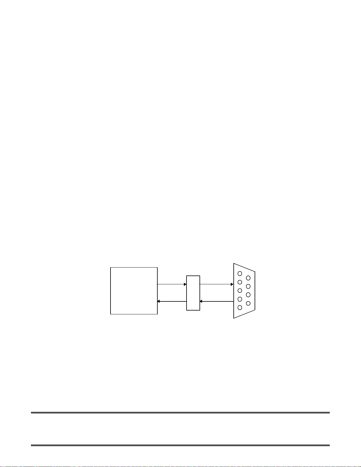
Figure 2 shows the connection between the ADSP-2181 and the line driver ADM232AAR. The
FLAG IN and FLAG OUT pins are used as independent receive and transmit lines.
DSP ADM232AAR RS-232 Connector
ADSP-2181 FO RX
FI TX
Figure 2 - EZ Kit Lite System Configuration
EE-89 Page 6
Technical Notes on using Analog Devices’ DSP components and development tools
Phone: (800) ANALOG-D, FAX: (781) 461-3010, FTP: ftp.analog.com, EMAIL: dsp.support@analog.com
Page 7

4. SOFTWARE
4.1 Data Format
The UART program supports most common baud rates. However, the autobaud feature can only
detect 2400, 3600, 9200 and 19200 baud. The word to be transmitted or received should have 8 data bits
and no parity bit. The program adds 1 start bit and 1 stop bit automatically when transmitting.
4.2 Program Flow
The UART program consists of the following subroutines:
• Automatic baud rate detection routine (autobaud)
• Initialization routine
• Bit processing timer interrupt service routine (uart_isr)
• Transmit routine (trans_bit)
The Automatic baud rate detection routine must be called first after a system reset. This subroutine
will wait for a ASCII ‘8’ character to be downloaded from the serial device. Then this subroutine configures
Serial Port 1 as the FLAG IN and FLAG OUT pin for receiving and transmitting. Once the character is
received, the routine figures out the current baud rate setting of the serial device and pass it on to the initialization
routine.
The Initialization routine must be called after the automatic baud rate detection routine. This routine
reads the detected baud rate constant from the autobaud routine and sets the internal timer of the UART to
match the baud rate. Then this subroutine configures Serial Port 1 as the FLAG IN and FLAG OUT pin for
receiving and transmitting. The status flags of the UART are set or reset here to indicate that the UART is ready
for operation.
After the autobaud and initialization routines are called upon after system reset, the Bit processing
timer interrupt service routine is called. This happens every time the timer expires and issues an interrupt.
This routine will set or reset the FLAG OUT pin to transmit one bit at a time if there is a character to be sent
out. The routine then checks to see If there are bits to be received from the FLAG IN pin by polling the FLAG
EE-89 Page 7
Technical Notes on using Analog Devices’ DSP components and development tools
Phone: (800) ANALOG-D, FAX: (781) 461-3010, FTP: ftp.analog.com, EMAIL: dsp.support@analog.com
Page 8

IN pin continuously to look for the start bit (logic low). If the start bit is detected, the routine will shift in one bit
at a time and signal if a whole character has been received.
The Transmit routine is used to send a character transmit request to the UART. This routine copies the
character to be transmitted to the transmit buffer with the correct number of stop and start bits added. The
transmit routine then sets a flag to notify the UART that a character is waiting to be transmitted.
EE-89 Page 8
Technical Notes on using Analog Devices’ DSP components and development tools
Phone: (800) ANALOG-D, FAX: (781) 461-3010, FTP: ftp.analog.com, EMAIL: dsp.support@analog.com
Page 9
4.3 Automatic Baud Rate Detection Routine
For the software UART to function properly, the program must know the baud rate setting of the serial
device that it is trying to communicate with. Instead of setting the baud manually, this autobaud feature of the
UART will automatically detect and match the current serial device’s baudrate.
The autobaud subroutine must be called after a system restart. The user should transmit an ‘8’ from the
serial terminal to the EZ Kit Lite board at restart. The character ‘8’ was chosen because
representation has 3 consecutive high bits with all other bits low. Autobauding works as follows:
1. The subroutine loads the timer with maximum value (0xFFFF).
2. The subroutine waits for a start bit (0) by polling the FLAG IN pin.
3. When a start bit is detected, the routine waits for the beginning of the three high bits in ‘8’’s ASCII
representation to arrive.
4. The timer counts down during the receiving period of the 3 high bits.
5. The number of cycles taken to receive those 3 bits is then compared to the number of cycles a known
baud rate took to receive 3 bits.
6. If a match is found, the autobaud sets the timer constant to operate the UART at the same baud rate.
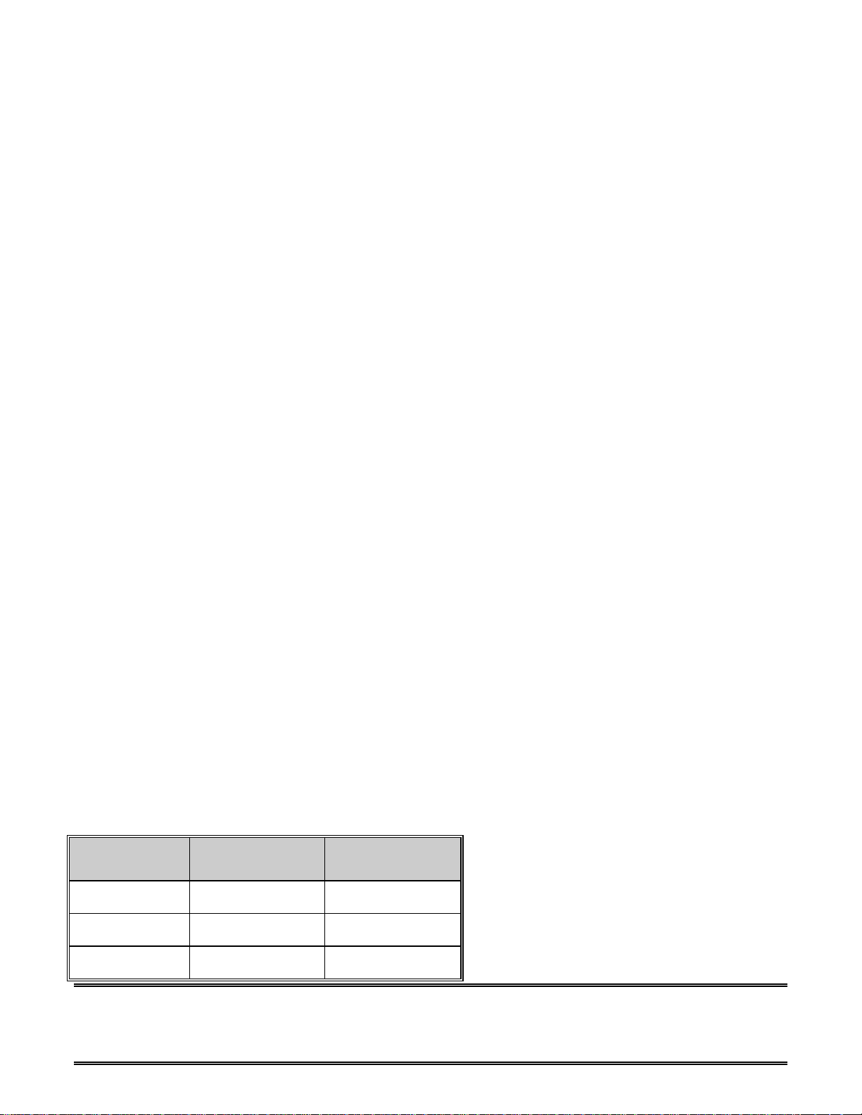
The number of cycles needed to process 3 bits and the timer constant for common baud rates can be
found by using the following formula. Use the following formula to find the number of cycles needed for
processing 1/3 bit:
Number of Cycles Needed to process 1/3 bit = ( ( processor frequency / ( 3 * baud rate ) ) - 1 *
BAUD Rate
(bits/sec)
Cycles Needed
for 3 Bits
Cycles Needed
for 1/3 Bit
2400 41661 4629
4800 20826 2314
9600 10404 1156
EE-89 Page 9
Technical Notes on using Analog Devices’ DSP components and development tools
Phone: (800) ANALOG-D, FAX: (781) 461-3010, FTP: ftp.analog.com, EMAIL: dsp.support@analog.com
Page 10

19200 5202 578
Table 1 - Timer constants and number of cycles for the common baud rates
* The processor runs at 33 MHz on the ADSP-2181 EZ-Kit Lite
EE-89 Page 10
Technical Notes on using Analog Devices’ DSP components and development tools
Phone: (800) ANALOG-D, FAX: (781) 461-3010, FTP: ftp.analog.com, EMAIL: dsp.support@analog.com
Page 11

{*****************************************************
* Name: auto
* input: none
* output: none
*
* description: This function figures out the terminal’s
* baud rate by counting the cycle time
* to tx 3 bits. This function waits for
* the char '8' to be downloaded from the
* terminal and calculates the time constant.
* This time constant is compared to known
* constant of different baudrates.
* Once the baudrate is known, it returns
* a variable which is then used by UART to
* clock in or transmit chars.
*
* note: Should be called before initialize in
* the main program. ASCII for char '8'
* is: 00111000. LSB is rx first.
*
* #cycles/(1/3 bit) = (freq/(3*Baudrate)) - 1
*
* baudrate #cycles/3 bits #cycles/(1/3 bit)
* -----------------------------------------------------* 2400 41668 4630
* 4800 20834 2315
* 9600 10417 1157
* 19200 5208 579
********************************************************}
.module autobaud;
.include <system.k>;
.var baud_const; { used in uart.dsp }
.global baud_const;
.entry auto; { used in main program }
auto:
{ set timer to count from 0xFFFF }
dis timer;
ax0 = 0xffff;
dm(TCOUNT) = ax0;
EE-89 Page 11
Technical Notes on using Analog Devices’ DSP components and development tools
Phone: (800) ANALOG-D, FAX: (781) 461-3010, FTP: ftp.analog.com, EMAIL: dsp.support@analog.com
Page 12

dm(TPERIOD) = ax0;
ax0 = 0;
dm(TSCALE) = ax0;
{ wait for start bit -> 0 }
wait_start:
if flag_in jump wait_start;
{ looking for the 1st of 3 high bits in '8' }
wait_high:
if flag_in jump got_high;
jump wait_high;
got_high:
{ start counting down using the timer }
ena timer;
{ wait until 3 high bits have been rxed }
wait_low:
if flag_in jump wait_low; { wait for low bit }
{ stop counting down using the timer }
dis timer;
{ wait until the char '8' is finished }
wait_stop:
if not flag_in jump wait_stop;
{ find out how many cycles needed to rx 3 bit }
ay0 = dm(TCOUNT);
ax0 = 0xffff;
ar = ax0 - ay0;
ax0 = ar;
{ compare #cycles to known cycle # of diff baudrates }
ay0 = 31251; { is it 2400? }
ar = ax0 - ay0;
if ac jump baud2400;
ay0 = 15625; { is it 4800? }
ar = ax0 - ay0;
if ac jump baud4800;
EE-89 Page 12
Technical Notes on using Analog Devices’ DSP components and development tools
Phone: (800) ANALOG-D, FAX: (781) 461-3010, FTP: ftp.analog.com, EMAIL: dsp.support@analog.com
Page 13

ay0 = 7812; { is it 9600? }
ar = ax0 - ay0;
if ac jump baud9600;
{ buadrate found, setting the timer constant }
baud19200:
ax0 = 579;
dm(baud_const) = ax0;
jump baud_done;
baud9600:
ax0 = 1157;
dm(baud_const) = ax0;
jump baud_done;
baud4800:
ax0 = 2315;
dm(baud_const) = ax0;
jump baud_done;
baud2400:
ax0 = 4630;
dm(baud_const) = ax0;
baud_done:
rts;
.endmod;
Listing 4.1 Autobaud Program
EE-89 Page 13
Technical Notes on using Analog Devices’ DSP components and development tools
Phone: (800) ANALOG-D, FAX: (781) 461-3010, FTP: ftp.analog.com, EMAIL: dsp.support@analog.com
Page 14

4.4 Initialization Routine
The initialization routine is called to prepare and set up the UART to transmit and receive a character.
First, this routine gets the timer constant and sets the timer to issue interrupts at 3 times the baud rate. This
provides sufficient clock resolution to handle the asynchronous data stream. For applications requiring greater
resolution, the interrupt rate may be changed to higher odd multiples of the baud rate.
The initialization routine next configures Serial Port 1 (SPORT1) as the FLAG IN and FLAG OUT
pins. This routine then sets the FLAG OUT pin high to indicate an idle line. Finally, all pending interrupts are
cleared, the timer is enabled, and it starts to count down.
4.5 Bit Processing Timer Interrupt Service Routine
Two interrupt service routine is the central routine of the UART program. This routine is executed
every time the timer counter expires and issues an interrupt. Since the timer is running at three times the baud
rate, it will be called three times for every bit transmitted or received. The interrupt service routine is divided
into two sections, the transmit section and the receive section.
The routine begins by switching to the secondary set of registers in order to preserve the register content
for the main program. Next, this routine checks the transmit flag to see if there is a transmit request. If there is
a character to be transmitted, the transmit section is executed; if not, the routine skips the transmit section and
jumps directly to the receive section.
Because the timer runs at three times the baud rate, a bit will be sent once every three timer interrupts
while in transmit mode. The transmit section must decide if a bit should be sent during the current interrupt. If a
bit is to be transmitted, the routine shifts the word in the transmit buffer out, LSB first. This bit will determine
whether the FLAG OUT pin is set high or low. The routine will then update all the necessary transmit flags and
then execute the receive section.
The receive section first checks to see if the stop bit of the last word have been received. If it has, the
routine waits for the stop bit period to pass and returns to the main routine. If the stop bit has not been
received, the receiver is either in the middle of receiving a word or waiting to receive a new word.
EE-89 Page 14
Technical Notes on using Analog Devices’ DSP components and development tools
Phone: (800) ANALOG-D, FAX: (781) 461-3010, FTP: ftp.analog.com, EMAIL: dsp.support@analog.com
Page 15

When the receiver is waiting for a new word, it samples the FLAG IN pin to check for a start bit. If
none is found, the routine returns to the main routine. If a start bit is detected, the routine sets the receive
counter to one more than the normal count. This is done so the UART can sample near the middle of each bit in
the data stream. When the receiver is in the middle of receiving a word, the routine will sample the FLAG IN
pin and shift in a bit once every three timer interrupts until there are no more bits left to be received. The
receiver will set the word ready flag and update the necessary flags to indicate a word has been received.
4.6 Transmit Routine
This routine is called in the main program to transmit a character using UART. It copies the word to be
transmitted from the AX1 register to the transmit buffer with stop and start bits added. The routine then sets the
transmit request flag to notify the UART that a character is waiting to be transmitted. If the UART is busy, this
routine will wait in a loop until the UART transmitter becomes available.
{*********************************************************
* File: uart.dsp
* Contains: Initialize
* Trans_bit
* UART_ISR
*********************************************************}
.module UART;
.include <system.k>;
.const CRYSTAL = 16667; { EZ-KIT LITE's crystal kHZ freq.}
{-----Defined in the main module-----}
.external num_tx_bits;
.external num_rx_bits;
{-----Defined in the autobaud module-----}
.external baud_const;
{-----global functions-----}
.entry trans_char;
.entry initialize;
.entry uart_isr;
EE-89 Page 15
Technical Notes on using Analog Devices’ DSP components and development tools
Phone: (800) ANALOG-D, FAX: (781) 461-3010, FTP: ftp.analog.com, EMAIL: dsp.support@analog.com
Page 16

{-----transmit variables-----}
.var uart_tx_buffer; { bits are tx from this buffer }
.var tx_bits_left; { contains # of bits left to tx }
.var main_tx_buffer; { contains the word to be txed }
.var tx_counter; { uart txs when the count=0 }
.var tx_flag; { 1=transmit request, 0=no req }
{-----receive variables-----}
.var uart_rx_buffer; { bits are rx into this buffer }
.var main_rx_buffer; { contains the rx word }
.var rx_bits_left; { contains # of bits left to rx }
.var incomming; { 1=uart is in the middle of rx }
.var rx_counter; { uart clocks in a bit when = 0 }
.var rx_a_word; { signals main prog a word ready }
.var stop_bit; { 1 = stop bit period reached }
.global main_rx_buffer;
.global rx_a_word;
{**********************************************************************
* Name: initialize
* input: non e
* output: none
*
* description: This function sets the timer to generate
* interrupts at three times the baud rate.
* It also configures Serial Port 1, (SPORT1)
* , as the FLAG IN and FLAG OUT pin s.
* It then sets flags that indicate the UART
* is ready to tx and rx. Finally the FLAG
* OUT pin is set and the timer is enabled.
*
* notes: This function should be called at the
* beginning of the main routine.
*************************************************************************}
initialize:
{ Initialize the timer to tick @ 3x Baudrate }
ax0 = dm(baud_const); { set by autobaud }
dm(TCOUNT) = ax0;
dm(TPERIOD) = ax0;
EE-89 Page 16
Technical Notes on using Analog Devices’ DSP components and development tools
Phone: (800) ANALOG-D, FAX: (781) 461-3010, FTP: ftp.analog.com, EMAIL: dsp.support@analog.com
Page 17

ax0 = 0;
dm(TSCALE) = ax0;
{ Initialize UART status flags }
set flag_out; { set high for idle state }
dm(tx_flag) = ax0; { no tx request }
dm(incomming) = ax0; { not rxing a word }
dm(rx_a_word) = ax0; { no rx word ready }
dm(stop_bit) = ax0;
ax0 = 1;
dm(tx_counter) = ax0; { load the tx counter }
{ clear all pending interrupts }
ifc = b#00000011111111;
nop; { take care of ifc latency }
{ Enable and set up SPORT1 as FI and FO pin }
ax0 = b#0000100000000000;
ay0 = System_Control_Reg;
ar = ax0 or ay0; { enable SPORT1 }
ay0 = b#1111101111111111;
ar = ar and ay0; { set up SPORT1 as FI/O }
{ Enable timer interrupt and start timer count down }
ax0 = imask;
ay0 = b#0000000001;
ar = ax0 or ay0;
imask = ar; { enable timer int }
ena timer; { start timer count down }
rts;
{**********************************************************
* Name: uart_isr
* input: none
* output: none
*
* description: This ISR is called every time the timer
* expires and issues an interrupt. This
* routine will xmit one bit at a time using
* the flag out pin. If there is a word to be
EE-89 Page 17
Technical Notes on using Analog Devices’ DSP components and development tools
Phone: (800) ANALOG-D, FAX: (781) 461-3010, FTP: ftp.analog.com, EMAIL: dsp.support@analog.com
Page 18

* received, the routine will shift in bits by
* reading the flag in pin.
*
* note: Since the internal timer is running at 3x
* baud rate, bits are processed only once
* for every 3 timer interrupts.
***********************************************************}
uart_isr:
ena sec_reg; { save content of registers }
{ Something to Transmit? }
ax0 = dm(tx_flag); { Is there a tx request? }
none = pass ax0;
if eq jump receive; { if not goto receive, if yes..}
transmit:
{ Decrement the transmit counter }
ay0 = dm(tx_counter);
ar = ay0 - 1;
dm(tx_counter) = ar;
{ Send out a char. during this interrupt? }
if ne jump receive; { if not goto receive, if yes..}
{ Shift out tx buffer's LSB into SR0. Test it to }
{ set or reset the flag out pin }
sr1 = dm(uart_tx_buffer);
sr0 = 0;
sr = lshift sr1 by -1 (hi);
dm(uart_tx_buffer) = sr1;
ar = pass sr0;
if ge reset flag_out; { test the sign bit of SR0}
if lt set flag_out;
{ Reload the transmit counter }
ax0 = 3; { 3 interrupts later transmit again }
dm(tx_counter) = ax0;
{ Decrement the bits left to transmit counter }
ax0 = dm(tx_bits_left);
EE-89 Page 18
Technical Notes on using Analog Devices’ DSP components and development tools
Phone: (800) ANALOG-D, FAX: (781) 461-3010, FTP: ftp.analog.com, EMAIL: dsp.support@analog.com
Page 19

ar = ax0 - 1;
dm(tx_bits_left) = ar;
if ne jump receive; { finished with current word? }
{ if no, goto receive without }
{ clearing the busy and the }
{ tmit request flag: tx_flag }
ax0 = 0; { yes, finished with current }
{ word. setup status flags }
dm(tx_flag) = ax0;
receive:
{ got stop bit of the last word yet? }
ax0 = dm(stop_bit);
ar = pass ax0;
if ne jump stop_rxed;
{ If rx not busy, check for a start bit, if none, exit isr }
ax0 = dm(incomming); { in the middle of rx a word? }
ar = pass ax0;
if ne jump word_in; { yes, goto rx routine }
if flag_in jump done; { no, then look for start bit }
{ start bit found, clear rx buffer and set busy flag }
ax0 = 0;
dm(uart_rx_buffer) = ax0;
ax0 = 1;
dm(incomming) = ax0;
{ set the timer counter to sample the center of the bit }
ax0 = 4; { set to 4 to adjust timeing }
dm(rx_counter) = ax0;
{ get number of bits in a word from main program }
ax0 = dm(num_rx_bits);
dm(rx_bits_left) = ax0;
rti;
word_in:
{ decrement timer counter, if expired then take in a bit }
ay0 = dm(rx_counter);
EE-89 Page 19
Technical Notes on using Analog Devices’ DSP components and development tools
Phone: (800) ANALOG-D, FAX: (781) 461-3010, FTP: ftp.analog.com, EMAIL: dsp.support@analog.com
Page 20

ar = ay0 -1;
dm(rx_counter) = ar;
if ne jump done; { exit isr if not expired }
{ timer expired, shift a bit into the buffer }
ay0 = 0x0100; { 1's are shifted from here }
ar = dm(uart_rx_buffer);
if not flag_in jump shift_zero; {flag in high or low?}
ar = ar + ay0; { high, shift in a one }
shift_zero: { low, shift in a zero }
sr = lshift ar by -1 (lo);
dm(uart_rx_buffer) = sr0;
{ Decrement bits left counter }
ay0 = dm(rx_bits_left);
ar = ay0 - 1;
dm(rx_bits_left) = ar;
{ Reset the timer counter }
ax0 = 3;
dm(rx_counter) = ax0;
if ne jump done; { more bits for current word? }
ax0 = 1; { no more, wait for stop bit }
dm(stop_bit) = ax0;
stop_rxed:
{ wait till stop bit passes }
ay0 = dm(rx_counter);
ar = ay0 - 1;
dm(rx_counter) = ar;
if ne jump done; { stop bit period passed yet? }
{ No more bits left for current word, copy it to main buff }
ax0 = dm(uart_rx_buffer);
dm(main_rx_buffer) = ax0;
{ Reset status flags }
ax0 = 0;
dm(incomming) = ax0;
dm(stop_bit) = ax0;
EE-89 Page 20
Technical Notes on using Analog Devices’ DSP components and development tools
Phone: (800) ANALOG-D, FAX: (781) 461-3010, FTP: ftp.analog.com, EMAIL: dsp.support@analog.com
Page 21

{ signal main program there is a word ready }
ax0 = 1;
dm(rx_a_word) = ax0;
done:
rti;
{*************************************************************************
* Name: trans_char
* Input: ax1 <-- ASCII char to be transmitted
* output: none
*
* description: This function is called in the main routine
* to transmit a char using UART. It sets
* the transmit flag to notify the UART that a
* char is waiting to be transmitted. I t then
* copies the main transmit buffer to the UART
* tansmit buffer with stop and start bit added
***************************************************************************}
trans_char:
{ Is the transmitter busy? Wait if it is }
wait: ax0 = dm(tx_flag);
none = pass ax0;
if ne jump wait;
{ The number of bits will be defined in main routine }
ax0 = dm(num_tx_bits);
dm(tx_bits_left) = ax0;
{ copy the char. to the internal transmit buffer }
dm(main_tx_buffer) = ax1;
sr1 = ax0; { init SR1 to be 0 }
sr0 = b#1111111000000000; { adding stop bit }
ar = dm(main_tx_buffer);
sr = sr or lshift ar by 1 (lo); { adding start bit }
dm(uart_tx_buffer) = sr0;
{ set the transmit flag }
ax0 = 1;
dm(tx_flag) = ax0;
EE-89 Page 21
Technical Notes on using Analog Devices’ DSP components and development tools
Phone: (800) ANALOG-D, FAX: (781) 461-3010, FTP: ftp.analog.com, EMAIL: dsp.support@analog.com
Page 22

rts;
.endmod;
Listing 4.2 Software UART Program
EE-89 Page 22
Technical Notes on using Analog Devices’ DSP components and development tools
Phone: (800) ANALOG-D, FAX: (781) 461-3010, FTP: ftp.analog.com, EMAIL: dsp.support@analog.com
Page 23

5. EXAMPLE PROGRAM
5.1 Introduction
echo.dsp is an example of a program that uses the software UART routine to transmit and receive. This
example will show how to use the UART routine. The program will read in a character from a serial device and
echo it back.
For this example you will need a PC and the ADSP-2181 EZ Kit Lite board connected to one of the
comm. ports.
5.2 Program Files
The following files are needed to create the example program:
• uart.dsp UART program subroutine.
• autobaud.dsp UART automatic baud detection subroutine.
• echo.dsp Main program that echoes characters back.
• uart.ach UART system architecture file.
• make.bat DOS batch file that assembles, links and creates a PROM file for the files
listed above.
The make.bat batch file should be used to create the executable and the PROM file for the example
program. The user should burn or download the PROM file to the EZ Kit Lite’s EPROM after the make.bat
file successfully creates the echo.exe and echo.bnm files.
5.3 The Main Routine
The main echo routine uses the software UART subroutine to receive and transmit character back to
the serial device. The main routine first uses the autobaud routine to automatically determine what the current
baud rate of the serial device is. Then the main routine calls the initialization routine to match the baud rate and
prepare the software UART for transmit and receive characters.
EE-89 Page 23
Technical Notes on using Analog Devices’ DSP components and development tools
Phone: (800) ANALOG-D, FAX: (781) 461-3010, FTP: ftp.analog.com, EMAIL: dsp.support@analog.com
Page 24

When the serial device’s baud rate is successfully detected by the autobaud routine, the main routine will
send a string of text to the terminal displaying the detected baud rate. The routine will then loop to wait for a
character available flag from the UART. If one is available, the main routine will place the character in the
transmit register (AX1) and call the transmit routine to send it back out.
Listings of all the program files and system files needed for the example program are included in this
document. Information on the EZ Kit Lite board and the ADSP-2181 can be found in the ADSP-2100 Family
EZ-Kit Lite Reference Manual.
{*****************************************************
* Name: echo
* Input: none
* Output: none
*
* Description: This program uses the UART driver and
* the autobaud detection function to echo
* back any char it receives. First, it
* varifies the functionality of the auto
* baud by sending a text string back
* to the terminal. After sending the
* text string, the program checks to see
* if a word is ready from the UART driver.
* If it is, the trans_char function is
* then used to send the char back to
* terminal.
*
* calls: initialize
* auto
* trans_char
******************************************************}
.module echoing;
.include <system.k>;
.entry start; { for the interrupt vector table }
.external initialize;
.external trans_char;
.external rx_a_word;
EE-89 Page 24
Technical Notes on using Analog Devices’ DSP components and development tools
Phone: (800) ANALOG-D, FAX: (781) 461-3010, FTP: ftp.analog.com, EMAIL: dsp.support@analog.com
Page 25

.external main_rx_buffer;
.external auto;
.external baud_const;
.var num_tx_bits; { num of tx bits including }
{ start and stop bits }
.var num_rx_bits; { num of data bits in a rx word }
.global num_tx_bits;
.global num_rx_bits;
{-sent to terminal when autobaud is successful-}
.var text[20];
.var text1[20];
.var text2[20];
.var text3[20];
.init text: 'r','u','n','n','i','n','g',' ','a','t',
' ','1','9','2','0','0',0;
.init text1: 'r','u','n','n','i','n','g',' ','a','t',
' ','9','6','0','0',0;
.init text2: 'r','u','n','n','i','n','g',' ','a','t',
' ','4','8','0','0',0;
.init text3: 'r','u','n','n','i','n','g',' ','a','t',
' ','2','4','0','0',0;
{*****************************************************}
start:
imask = b#0000000000;
icntl = b#00010;
mstat = b#1000000;
ax0 = b#0000000000000000; dm (System_Control_Reg) = ax0;
{ boot up with a led blink }
toggle fl1;
{ set numbe of data bits in a word }
ax0 = 10;
dm(num_tx_bits) = ax0;
ax0 = 8;
EE-89 Page 25
Technical Notes on using Analog Devices’ DSP components and development tools
Phone: (800) ANALOG-D, FAX: (781) 461-3010, FTP: ftp.analog.com, EMAIL: dsp.support@analog.com
Page 26

dm(num_rx_bits) = ax0;
l0 = 0;
m0 = 1;
{ auto detect the terminal baudrate }
call auto; { user must tx an '8' at this time }
{ initialize the UART for tx and rx }
call initialize;
{ display detected baud rate on terminal }
ax0 = dm(baud_const);
ay0 = 579;
ar = ax0 - ay0;
if eq jump dis_19200;
ay0 = 1157;
ar = ax0 - ay0;
if eq jump dis_9600;
ay0 = 2315;
ar = ax0 - ay0;
if eq jump dis_4800;
dis_2400:
{ baud rate 2400 detected }
i0 = ^text3;
jump text_done;
dis_4800:
{ baud rate 4800 detected }
i0 = ^text2;
jump text_done;
dis_9600:
{ baud rate 9600 detected }
i0 = ^text1;
jump text_done;
dis_19200:
{ baud rate 19200 detected }
i0 = ^text;
EE-89 Page 26
Technical Notes on using Analog Devices’ DSP components and development tools
Phone: (800) ANALOG-D, FAX: (781) 461-3010, FTP: ftp.analog.com, EMAIL: dsp.support@analog.com
Page 27

jump text_done;
text_done:
ax1 = dm(i0, m0);
ar = pass ax1;
if eq jump line_feed;
call trans_char;
jump text_done;
line_feed:
ax1 = 13;
call trans_char;
ax1 = 10;
call trans_char;
again:
{ wait until a char is received.... }
ax0 = dm(rx_a_word);
ar = pass ax0;
if eq jump again;
{ received a char., put it in ax1 to echo back }
ax1 = dm(main_rx_buffer);
{ clear word ready flag }
ax0 = 0;
dm(rx_a_word) = ax0;
{ send the char back out }
call trans_char;
{ wait until a char is received..... }
jump again;
.endmod;
Listing 5.1 Echo Example Program
{***************************************************************
* Name: ivt
*
* Description:This is the interrupt vector table. It will be
EE-89 Page 27
Technical Notes on using Analog Devices’ DSP components and development tools
Phone: (800) ANALOG-D, FAX: (781) 461-3010, FTP: ftp.analog.com, EMAIL: dsp.support@analog.com
Page 28

* placed in 0x0000..0x002f, the interrupt vectors
* area.
***************************************************************}
.module/ram/abs=0 interrupt;
.external start;
.external uart_isr;
jump start; rti; rti; rti; {00: reset }
rti; rti; rti; rti; {04: IRQ2 }
rti; rti; rti; rti; {08: IRQL1 }
rti; rti; rti; rti; {0c: IRQL0 }
rti; rti; rti; rti; {10: SPORT0 tx }
rti; rti; rti; rti; {14: SPORT1 rx }
rti; rti; rti; rti; {18: IRQE }
rti; rti; rti; rti; {1c: BDMA }
rti; rti; rti; rti; {20: SPORT1 tx or IRQ1 }
rti; rti; rti; rti; {24: SPORT1 rx or IRQ0 }
jump uart_isr; rti; rti; rti; {28: timer }
rti; rti; rti; rti; {2c: power down }
.endmod;
Listing 5.2 Interrupt Vector Table
EE-89 Page 28
Technical Notes on using Analog Devices’ DSP components and development tools
Phone: (800) ANALOG-D, FAX: (781) 461-3010, FTP: ftp.analog.com, EMAIL: dsp.support@analog.com
 Loading...