

Page 1
Engineer to Engineer Note EE-84
Technical Notes on using Analog Devices’ DSP components and development tools
Phone: (800) ANALOG-D, FAX: (781) 461-3010, EMAIL: dsp.support@analog.com, FTP: ftp.analog.com, WEB: www.analog.com/dsp
Copyright 1999, Analog Devices, Inc. All rights reserved. Analog Devices assumes no responsibility for customer product design or the use or application of customers’ products or
for any infringements of patents or rights of others which may result from Analog Devices assistance. All trademarks and logos are property of their respective holders. Information
furnished by Analog Devices Applications and Development Tools Engineers is believed to be accurate and reliable, however no responsibility is assumed by Analog Devices
regarding the technical accuracy of the content provided in all Analog Devices’ Engineer-to-Engineer Notes.
SHARC DMA Modes of Operation:
Last Modified: 3/16/98
Q:
What are the differences between the external port
DMA modes on the SHARC family processors?
What signals are used for a specific DMA
configuration? How do I configure the DSP(s) with
external devices such as memory or “smart” devices
like an FPGA?
The MASTER, HSHAKE, and EXTERN bits of
each DMACx control register are used to select the
DMA mode of operation. Each external port DMA
channel can be set up to operate in one of five DMA
modes. The master mode initiates transfers while the
other modes act as “slaves”, where an external
device must initiate each transfer.
A:
There are five different types of external port DMA
modes; slave mode, handshake mode, external
handshake mode, master mode, and paced master
mode. Each external port DMA channel has its own
control register. The registers are named DMAC6
through DMAC9, corresponding to DMA channels
six through nine. Please note that for the 21061
SHARC processor, only channels six and seven of
the external port are applicable.
External Port DMA Modes
MODE OPERATION
Slave Int Memory <--> DMA Buffer
Master Int Memory <--> DMA Buffer <--> Ext Memory
uses strobes & address, no DMAR & DMAG
Paced Master Int Memory <--> DMA Buffer <--> Ext Memory
uses DMAR & strobes & address, no DMAG
Handshake Int Memory <--> DMA Buffer <--> Ext Latch/Buffer
uses DMAR & DMAG, no strobes or address
Ext Handshake Ext Latch/Buffer <--> Ext Memory
uses DMAR & DMAG & strobes & address
Figure 1: External Port DMA Modes
M H E DMA Mode of Operation
0 0 0 Slave Mode
0 1 0 Handshake Mode
0 1 1 External Handshake Mode
1 0 0 Master Mode
1 1 0 Paced Master Mode
Figure 2: MASTER, HSHAKE, and EXTERN bits of DMACx
control register
*Please note that all other assignments of the
MASTER, HSHAKE, and EXTERN bits
(001,101,111) are reserved, and should not be
used.
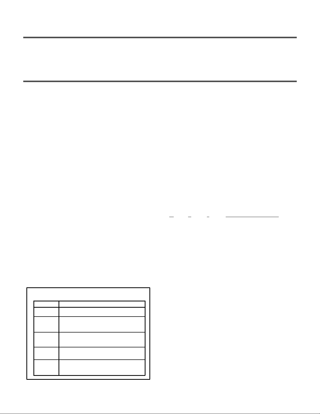
SLAVE MODE:
When a particular DMA channel is configured as a
slave, this means that this particular DMA channel
cannot independently initiate external memory
transfers no matter what the programmed direction
of data transfer. The TRAN bit of the DMACx
control register determines the direction of the data
transfer. In a slave configuration, the external host
Page 2
device can write directly to the SHARC’s external
port buffer.
Slave Mode Configuration
SHARC (slave)
REDY
/RD
/WR
DATA
EPBx
ADDRESS
HOST
/RD
/WR
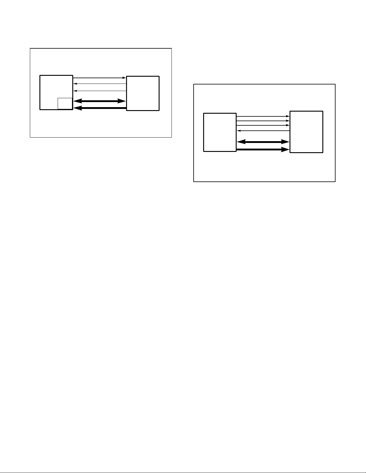
the DMA sequence is completed. Master mode can
be specified independently for each external port
DMA channel. In this configuration, the SHARC
asserts the appropriate external address, /RD and
/WR strobes, but does not use the /DMARx and
/DMAGx signals.
Master Mode Configuration
SHARC (master)
MS (memory)
/RD
/WR
ACK
DATA
Memory / SHARC (slave)
CS (memory)
/RD
/WR
ACK
Figure 3: Example Slave Mode Configuration
For example, if an external device wishes to transfer
a block of data to a SHARC’s internal memory, the
host would write to the DMA channel parameter
registers, II, IM, and C and to the DMACx control
register to initialize the channel. Then the device
would begin writing data to the EPBx buffer,
monitoring the status of the REDY signal (for
asynchronous, host-driven accesses) or the ACK
signal (for synchronous accesses) of the SHARC in
case of a DMA hold off. A hold off occurs when the
EPBx FIFO becomes full. For the buffer to operate
in this fashion, the BHD (Buffer Hang Disable) bit
must be cleared in the SYSCON register. Figure 2
shows an example of a slave mode configuration
system between a host processor and a SHARC.
The same holds true for host reads in slave mode.
If internal DMA transfers cannot fill the EPBx FIFO
buffer at the same rate as the external device empties
it, the external device will be held off with the REDY
signal (for asynchronous, host-driven accesses) or
the ACK signal (for synchronous accesses). Again,
for the buffer to operate in this fashion, the BHD
(Buffer Hang Disable) bit must be cleared in the
SYSCON register.
MASTER MODE:
When a DMA channel is configured to operate in
master mode, the SHARC’s DMA controller will
generate internal DMA requests for this channel until
ADDRESS
Figure 4: Example Master Mode Configuration
In a multiple SHARC environment, the most efficient
method (i.e. maximum throughput) is to have a
master/slave DMA mode configuration. This
configuration allows for a 1 cycle/transfer data
throughput rate. Another advantage is that the slave
will generate an interrupt automatically upon
completion of the DMA transfer. The disadvantage
is that both the master and the slave must be
programmed for the appropriate DMA transfer.
Figure 2 shows an example master mode
configuration between a SHARC and external
memory or a slave SHARC.
HANDSHAKE MODE:
On the ADSP-21060 and the ADSP-21062, DMA
channels 7 and 8, for external port buffers EPB1 and
EPB2, each have a set of external handshake
controls. /DMAR1 and /DMAG1 are the request
and grant signals for EPB1 and channel 7, and
/DMAR2 and /DMAG2 are the request and grant
signals for EPB2 and channel 8.
On the ADSP-21061, DMA channels 7 and 6, for
external port buffers EPB1 and EPB0, each have a
set of external handshake controls. /DMAR1 and
/DMAG1 are the request and grant signals for EPB1
and channel 7, and /DMAR2 and /DMAG2 are the
request and grant signals for EPB0 and channel 6.
Page 3

External Handshake Mode Configuration
Handshake Mode Configuration
SHARC FPGA
DMARx
DMAGx
DATA
Figure 5: Example Handshake Mode Configuration
Note: If external port DMA channel is enabled
but the handshake signals will not be used, the
corresponding /DMARx signal should be kept
high.
These signals serve as a hardware handshake to
facilitate between the SHARC and an external
device which does not have bus mastership
capability.
SHARC (master)
DMARx
DMAGx
/RD
/WR
ACK ACK
ADDRESS
Figure 6: Example External Handshake Mode Configuration
FPGA
Memory
/RD
/WR
D
A
T
A
External handshake mode transfers require the
SHARC’s DMA controller to generate external
memory access cycles. /DMARx and /DMAGx
retain the same functionality in this mode, but instead
of simply generating /DMAGx, the SHARC also
outputs addresses, memory selects (MS
), /RD
3-0
and /WR strobes, and it also responds to ACK.
/DMAGx will be held low until ACK is released or
any waitstates are completed.
To request an access of the EPBx buffer, the
external device pulls /DMARx low. When the
SHARC recognizes the request, it begins to arbitrate
for the external bus, if it is not already the bus
master. When the SHARC becomes the bus master,
it drives /DMAGx low. The SHARC will keep
/DMAGx asserted until it sees /DMARx
deasserted. This allows the external device to hold
the SHARC until it is ready to proceed. Figure 4
shows an example handshake mode configuration
between a SHARC and a “smart” external device
such as an FPGA.
EXTERNAL HANDSHAKE MODE:
External devices can use the /DMARx and
/DMAGx handshake signals to control DMA
transfers between an external device and external
memory. In this mode, the SHARC operates as an
independent DMA controller.
The SHARC’s EPBx buffers do not latch or drive
any data, and no internal memory DMA transfers
are performed. The EI, EM, and EC registers of the
DMA channel must be preloaded to generate the
external memory addresses and word count.
For example, let’s say for your system design you
had an FPGA, a SHARC, and some external RAM,
with the SHARC configured in external handshake
mode. The /DMARx and /DMAGx signals would be
connected between the DSP and the FPGA, the
data bus connected between the FPGA and the
memory device. The SHARC would communicate
with the memory device using the address bus, /RD
and /WR signals, and possibly the ACK signal if
wait states are needed or to hold off the DSP.
Figure 5 shows an external handshake mode
between a SHARC, external memory device, and an
FPGA.
PACED MASTER MODE:
Page 4

In paced master mode, /DMARx requests operate
the same way as in handshake mode, but /DMAGx
is not active. The DSP responds to requests only
with the /RD and /WR strobes. In this configuration,
an external device such as an FPGA will assert the
/DMARx signal, allowing the SHARC access to the
external bus only when the FPGA is ready.
Paced Master Mode Configuration
SHARC (master)
DMARx
/RD
/WR
ACK ACK
DATA
ADDRESS
FPGA
Memory
/RD
/WR
Figure 7: Example Paced Master Mode Configuration
Paced master mode gets its name from the fact that
an external device (which also has control over the
external bus) can hold off the DSP from the bus only
when it is ready for a DMA transfer from the
SHARC. This differs from master mode, because in
master mode the SHARC is always in control of the
external bus. Paced master mode accesses can be
extended by the ACK pin, by waitstates
programmed in the WAIT register, and by holding
the /DMARx pin low. Example 6 shows a paced
master mode configuration example, where an
FPGA controls the DMA accesses, while the
SHARC has control of the system bus.
 Loading...