

Page 1
Engineer-to-Engineer Note EE-220
a
Technical notes on using Analog Devices DSPs, processors and development tools
Contact our technical support at dsp.support@analog.com and at dsptools.support@analog.com
Or vi sit our o n-li ne r esou rces htt p:/ /www.analog.com/ee-notes and http://www.analog.com/processors
Using External Memory with ADSP-2126x SHARC® DSPs
Contributed by Brian M. and Matt W. Rev 1 – January 12, 2004
Introduction
The addressing functionality of the Parallel Port
on the ADSP-2126x SHARC® family of DSPs
has changed greatly when compared to the other
SHARC family DSPs that have an External Port.
This EE-Note describes external memory
addressing and how to use the VisualDSP++®
development tools to handle address translation
and data reorganization via the LDF PACKING
command (for VisualDSP++ 3.0 with Service
Pack 1). A macro that helps the Symbol Manager
convert logical and physical addresses is also
explained.
device, the core only needs to specify the single
32-bit logical address; then, the External Port
automatically calculates the four physical
addresses and performs the four fetches needed
to acquire the entire 32-bit word.
In contrast, the ADSP-2126x family of DSPs
uses a Parallel Port that does not have the
address translation built-in, although it will sill
perform the data packing (e.g., building a 32-bit
word from four 8-bit words). The Parallel Port
operates on physical addresses only. Note that
each external address in the memory map does
not
External Memory Addressing
One significant difference between the Parallel
Port and the previous External Port is that the
Parallel Port no longer accepts logical addresses
from the core, instead requiring the physical
word address to be supplied to the DMA engine.
This change requires special considerations by
software developers wishing to use external
memory on the ADSP-2126x family.
Previous SHARC DSPs have always accessed
the external memory using logical (32-bit)
addressing (i.e., each external address in the
memory map corresponds to exactly one
complete word of data). The translation of each
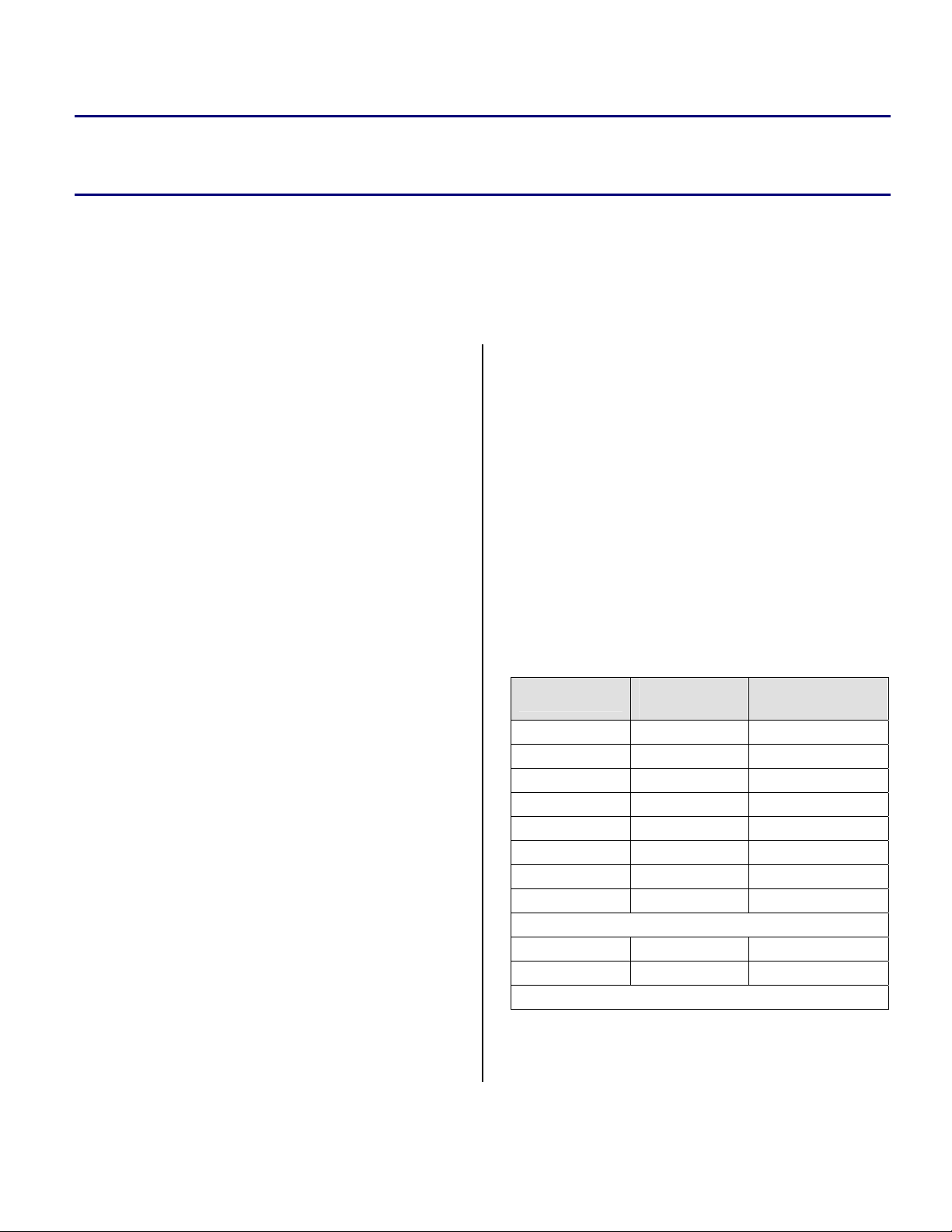
Logical Address
0x200000 0x200000 Word0 Byte1
0x200001 Word0 Byte2
0x200002 Word0 Byte3
0x200003 Word0 Byte4
0x200001 0x200004 Word1 Byte1
0x200005 Word1 Byte2
0x200006 Word1 Byte3
0x200007 Word1 Byte4
0x200100 0x200400 Word256 Byte1
0x200401 Word256 Byte2
Physical (Byte)
Address
...
...
Data
logical address into the four corresponding
physical addresses is handled transparently by
the hardware of the port. For example, if a 32-bit
Table 1. ADSP-21161 logical-to-physical address
translation by the external port.
word is fetched from an external byte-wide
Copyright 2004, Analog Devices, Inc. All rights reserved. Analog Devices assumes no responsibility for customer product design or the use or application of
customers’ products or for any infringements of patents or rights of others which may result from Analog Devices assistance. All trademarks and logos are property
of their respective holders. Information furnished by Analog Devices Applications and Development Tools Engineers is believed to be accurate and reliable, however
no responsibility is assumed by Analog Devices regarding technical accuracy and topicality of the content provided in Analog Devices’ Engineer-to-Engineer Notes.
Page 2
a
correspond to a complete word of data. Instead,
each logical (32-bit) word of data consumes
multiple address in the external range of the
memory map.
To illustrate this fact, compare the handling of
two consecutive 32-bit fetches on a ADSP-21161
SHARC DSP versus the same transaction on a
ADSP-21262 SHARC DSP. Table 1 shows the
corresponding physical addresses generated by
the External Port based on the logical addresses
from the which data is fetched. (Again, this
assumes 32/8 bit packing). Note that consecutive
logical addresses correspond to separate words
externally.
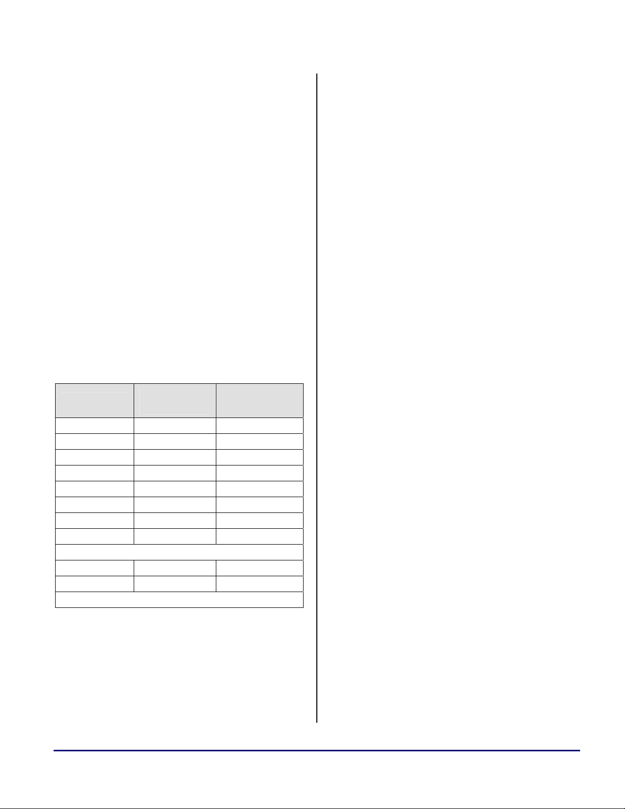
Table 2 highlights the difference in operation on
the ADSP-2126x family Parallel Port and
illustrates the lack of address translation between
the logical (32-bit) address and the physical (8bit in this case) address.
Logical Address
0x200000 0x200000 Word0 Byte1
0x200001 Word0 Byte2
0x200002 Word0 Byte3
0x200003 Word0 Byte4
0x200001 0x200001 Word0 Byte2
0x200002 Word0 Byte3
0x200003 Word0 Byte4
0x200004 Word1 Byte1
0x200100 0x200100 Word32 Byte1
0x200101 Word32 Byte2
Table 2. ADSP-2126x Logical to Physical address
mapping (not compatible with previous SHARC
addressing schemes).
Physical (Byte)
Address
...
...
Data
Fetching from consecutive logical addresses does
not properly access unique data in external
memory. The rest of this EE-note describes how
to deal with this new functionality in software.
The second change from previous SHARC DSPs
is that, in the ADSP-2126x family, it is necessary
to always use the External Index register (EIPP)
to access external memory; there is no direct core
access to external memory via the Data Address
Generators. The address in the EIPP register is
supplied directly to the AD pins in the address
cycle. (This ‘buffered-access’ architecture
effectively decouples the core from the Parallel
Port, enabling the core clock speed to be
doubled. It also allows the ADSP-2126x family
of DSPs to use fewer pins, significantly reducing
both DSP and system cost.)
Organizing Data for placement in
External Memory using the LDF
The first problem that the new Parallel Port
introduces is that it uses a physical word address,
rather than a logical word address. Because of
this, it is necessary to perform address translation
and data reorganization in software. In
VisualDSP++ 3.0 SP1, the LDF must include the
PACKING() command, enabling the linker to
generate addresses that the Parallel Port can use.
Listings 1 and 2 provide example packing
commands for a variety of possible cases when
packing into 8-bit memory and 16-bit memory,
respectively. The only case where a
PACKING() command would not be required is
when initializing 16-bit external memory with
16-bit data. In this one case, it so happens that
the logical addresses directly match the physical
addresses, so no translation/packing is needed.
The PACKING() command directs the linker to
reformat the data as it is placed into the DXE.
For a memory section of TYPE(DM RAM), each
memory address holds five bytes in the DXE
(regardless of whether the data is 40-, 32-, or 16bit logical data). For a TYPE(PM RAM) section,
each address corresponds to six bytes (regardless
of whether the data is 48-, 40-, 32-, or 16-bit
logical data). Before each word of data is
assigned an address by the linker, the
PACKING() command reorganizes the order of
Using External Memory with ADSP-2126x SHARC® DSPs (EE-220) Page 2 of 10
Page 3
a
the bytes in the DXE, and can add null bytes to
the DXE, if needed.
The loader and debugging tools (simulator and
emulator) expect the external memory sections
DXE to be in a certain format to initialize
external memory correctly.
For example, when a DM (5-byte) word is
mapped into an address in a memory segment
that is WIDTH(8), only the data in the fourth
most significant byte is placed at that external
address.
Similarly, for DM (5-byte) words mapped to a
memory segment that is WIDTH(16), only the
data in the third and fourth most significant bytes
are placed into the external address. (See Listings
1 and 2 for examples.)
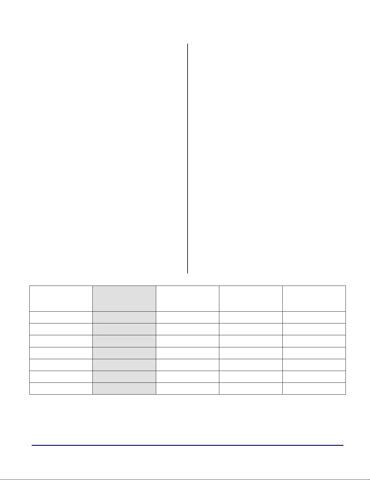
This means that if 32-bit data is mapped into
external 8-bit memory, 3 bytes of data are
uninitialized. To remedy this, translate the 32-bit
word into four words, placing the valid data into
th
the 4
most significant byte of each new word, as
shown in Table 3. (Refer to the Parallel Port
chapter of [1] ADSP-2126x SHARC DSP
Peripherals Manual for information about how
data is packed in external memory.)
The DSP’s internal memory is organized as four
16-bit-wide by 64K-deep columns which are
addressable as a variety of word sizes:
• 64-bit long word data (four columns)
• 48-bit instruction words or 40-bit extended-
precision normal word data (3 columns)
• 32-bit normal word data (2 columns)
• 16-bit short word data (1 column)
The four-columned memory architecture of the
ADSP-2126x family allows each location in
internal memory to be accessed in any of the
above formats, depending on the address used.
However, every access to the Parallel Port is 32bits (accesses are to 32-bit normal word space,
and counted in number of 32-bit words).
When transferring words that are not 32-bits
long, the External Count register must contain a
whole number of 32-bit words (i.e. it must be a
multiple of four). If it is not, the remainder bytes
are not transferred as expected. It is also
necessary to translate the internal address to 32bit word space.
External Width
WIDTH(8)
WIDTH(16)
Table 3. Packing in the DXE file for external memory.
Using External Memory with ADSP-2126x SHARC® DSPs (EE-220) Page 3 of 10
Corresponding
Address
0x01000000 0x0000001100 0x000000110000 0x44332211
0x01000001 0x0000002200 0x000000220000
0x01000002 0x0000003300 0x000000330000
0x01000003 0x0000004400 0x000000440000
0x02000000 0x0000112200 0x000011220000 0x33441122
0x02000001 0x0000334400 0x000033440000
DM Packed for
External Memory
PM Packed for
External Memory
32-bit Word
Transferred by
the DSP
Page 4

a
The following example translates the 48-bit
address 0x82694 to its 32-bit equivalent.
Translating from 16- or 64-bit space to 32-bit
space is as simple as shifting the entire address
by one bit (left-shift for 16-bit addresses, and
right-shift for 64-bit addresses). For 40/48-bit
addresses, which also use the normal word space
addresses, 48-bit addresses are offset from the
base address (0x80000 or 0xC0000) by twothirds of the offset of the 32-bit word.
Word space mask = 0x80000 or 0xC0000
(0x80000 in this case)
First remove the word space mask.
48-bit Offset = 0x82694 - 0x80000 = 0x2694
Then multiply the offset by 3/2.
32-bit Offset = 0x2694 * 3/2 = 0x39DE
Finally, reinsert the word space mask.
32-bit equivalent address = 0x839DE
When translating from 48-bit to 32-bit address,
only even 48-bit address translations are valid.
Odd 48-bit addresses fall in the middle of a 32bit word, and cannot be accessed properly.
Using External Memory with ADSP-2126x SHARC® DSPs (EE-220) Page 4 of 10
Page 5

a
8-bit External Memory Examples
MEMORY
{
seg_ext8 { TYPE(DM RAM) WIDTH(8) START(0x1200000) LENGTH(0x3FFF) }
seg_extpm8 { TYPE(PM RAM) WIDTH(8) START(0x1204000) LENGTH(0x3FFF) }
}
PROCESSOR p0
{
LINK_AGAINST( $COMMAND_LINE_LINK_AGAINST)
OUTPUT( $COMMAND_LINE_OUTPUT_FILE )
SECTIONS
{
seg_ext40into8
{
INPUT_SECTIONS( $OBJECTS(seg_ext40into8))
PACKING(5 B0 B0 B0 B5 B0
B0 B0 B0 B4 B0
B0 B0 B0 B3 B0
B0 B0 B0 B2 B0
B0 B0 B0 B1 B0)
} > seg_ext8
seg_ext32into8
{
INPUT_SECTIONS( $OBJECTS(seg_ext32into8))
PACKING(5 B0 B0 B0 B4 B0
B0 B0 B0 B3 B0
B0 B0 B0 B2 B0
B0 B0 B0 B1 B0)
} > seg_ext8
seg_ext16into8
{
INPUT_SECTIONS( $OBJECTS(seg_ext16into8))
PACKING(5 B0 B0 B0 B2 B0
B0 B0 B0 B1 B0)
} > seg_ext8
seg_extpm8
{
INPUT_SECTIONS( $OBJECTS(seg_extpm8))
PACKING (6 B0 B0 B0 B6 B0 B0
B0 B0 B0 B5 B0 B0
B0 B0 B0 B4 B0 B0
B0 B0 B0 B3 B0 B0
B0 B0 B0 B2 B0 B0
B0 B0 B0 B1 B0 B0)
} > seg_extpm8
}
Listing 1. Packing Examples for 8-bit External Memory
Using External Memory with ADSP-2126x SHARC® DSPs (EE-220) Page 5 of 10
Page 6

a
16-bit External Memory Examples
MEMORY
{
seg_ext16 { TYPE(DM RAM) WIDTH(16) START(0x1000000) LENGTH(0x3FFF) }
seg_extpm16 { TYPE(PM RAM) WIDTH(16) START(0x1004000) LENGTH(0x3FFF) }
}
PROCESSOR p0
{
LINK_AGAINST( $COMMAND_LINE_LINK_AGAINST)
OUTPUT( $COMMAND_LINE_OUTPUT_FILE )
SECTIONS
{
seg_ext40into16
{
INPUT_SECTIONS( $OBJECTS(seg_ext40into16))
PACKING(5 B0 B0 B5 B0 B0
B0 B0 B3 B4 B0
B0 B0 B1 B2 B0)
} > seg_ext16
seg_ext32into16
{
INPUT_SECTIONS( $OBJECTS(seg_ext32into16))
PACKING(5 B0 B0 B3 B4 B0
B0 B0 B1 B2 B0)
} > seg_ext16
seg_ext16into16
{
INPUT_SECTIONS( $OBJECTS(seg_ext16into16))
} > seg_ext16
seg_extpm16
{
INPUT_SECTIONS( $OBJECTS(seg_extpm16))
PACKING (6 B0 B0 B0 B5 B6 B0
B0 B0 B0 B3 B4 B0
B0 B0 B0 B1 B2 B0)
} > seg_extpm8
}
Listing 2. Packing Examples for 16-bit External Memory
Using External Memory with ADSP-2126x SHARC® DSPs (EE-220) Page 6 of 10
Page 7

a
Symbols in External Memory
As of VisualDSP++ 3.0 SP1 (the first version to
support the ADSP-2126x family of DSPs), the
Symbol Manager supports the use of logical
addresses only. Therefore, any symbol that
resides in external memory, except for the first in
a declared memory section, will be incorrect by a
value dependent upon the width of the external
memory and the address decoder setup. As
explained above, the Parallel Port of the ADSP2126x family uses physical addresses. The
difference between the logical and physical
address depends on memory type used (PM or
DM), the width of the external memory (8- or
16-bits), and the packing. Since this difference is
predictable, it is possible to use a preprocessor
macro to obtain the correct address. (Declaring a
separate memory section in the LDF for each
external buffer would also avoid this problem,
since each buffer would be the first in its
declared memory section. Because this method
requires pre-build knowledge of the desired
external buffers and hard coding the sizes into
the LDF, it is undesirable.)
The packing commands in Listings 1 and 2
clearly shows the relationship between the
logical and physical address. Each packing
command represents one logical word, and each
line within the packing command represents one
physical address.
In the examples in Listings 3 and 4, one 32-bit
logical word is packed into four 8-bit physical
words. If two contiguous symbols are declared,
the second symbol will overlap with the first by
3 bytes (e.g., if the first resides physically at
0x1002000 and the second at 0x1002004, the
logical addresses stored by the Symbol Manager
will be 0x1002000 and 0x1002001,
respectively). If these symbols are used as
presented by the Symbol Manager, access to the
second word would begin at the second byte of
the first word and end with the first byte of the
second word. If a third 32-bit word is also
declared, access to this word would begin at the
third byte of the first word and end with the
second byte of the second word. Therefore, a
simple macro is necessary to correct the
inaccuracy of the Symbol Manager (see the
EXTERNAL_ADDRESS() macro in Listing 3).
Address Translation Macro Use Example
//Width of External Memory to be accessed (either 8 or 16 bits)
#define EXTERNAL_MEMORY_WIDTH 8
//Mask for address bits used by the address decoder
#define DECODER_MASK 0xFFFFFC00
//Mask for address bits used on the memory chip
#define ADDRESS_MASK 0x000003FF
//Define a macro to perform the calculation
#define EXTERNAL_ADDRESS(ADDR) ((ADDR & DECODER_MASK)|\
((ADDR & ADDRESS_MASK)*(32 / EXTERNAL_MEMORY_WIDTH)))
#include <def21262.h>
.section/dm seg_dm32;
.var ext8holder[5];
Using External Memory with ADSP-2126x SHARC® DSPs (EE-220) Page 7 of 10
Page 8

// ******************************************************************
// External
.section/dm seg_ext8;
.var ext8zeros[95];
.var ext8[5] = 0xE0811111, 0xE0822222, 0xE0833333, 0xE0844444, 0xE0855555;
// ******************************************************************
.global _main;
//Main code section
.section/pm seg_pmco;
_main:
//Enable the Parallel Port interrupt.
bit set lirptl PPIMSK;
bit set mode1 IRPTEN;
//Read in the External DM sections on variable at a time
r4=0;
dm(PPCTL)=r4;
r0=ext8holder;
dm(IIPP)=r0;
r0=1;
dm(IMPP)=r0;
dm(EMPP)=r0;
r0=@ext8holder;
dm(ICPP)=r0;
/*Calculate the correct location of the external buffer
(The symbol manager does not correctly calculate external locations)
r0=(ext8&0xFFFFFC00)|((0x3FF&ext8)*4); dm(EIPP)=r0;
So use the External Address Macro. */
r0=EXTERNAL_ADDRESS(ext8); dm(EIPP)=r0;
//External Count is 4x the internal count
r0=@ext8*4; dm(ECPP)=r0;
//Enable the Parallel Port
ustat1= PPBHC|PPDUR4|PPEN|PPDEN;
dm(PPCTL)=ustat1; nop;
idle;
r0=0;
dm(PPCTL)=r0;
r0=ext8zerosholder;
dm(IIPP)=r0;
r0=1;
dm(IMPP)=r0;
dm(EMPP)=r0;
r0=@ext8zerosholder;
a
Using External Memory with ADSP-2126x SHARC® DSPs (EE-220) Page 8 of 10
Page 9

dm(ICPP)=r0;
/*Use the external address macro again.*/
r0=EXTERNAL_ADDRESS(ext8zeros); dm(EIPP)=r0;
//External Count is 4x the internal count
r0=@ext8zeros*4; dm(ECPP)=r0;
//Enable the Parallel Port
ustat1= PPBHC|PPDUR4|PPEN|PPDEN;
dm(PPCTL)=ustat1; nop;
idle;
_main.end:
jump(pc,0);
Listing 3. Using the Address Translation macro
a
Memory Layout for Listing 3
MEMORY
{
seg_rth { TYPE(PM RAM) START(0x00080000) END(0x000800ff) WIDTH(48) }
seg_pmco { TYPE(PM RAM) START(0x00080100) END(0x000803ff) WIDTH(48) }
seg_dm32 { TYPE(DM RAM) START(0x000c0400) END(0x000c2fff) WIDTH(32) }
seg_ext8 { TYPE(DM RAM) WIDTH(8) START(0x1200000) LENGTH(0x3FF) }
}
PROCESSOR p0
{
LINK_AGAINST( $COMMAND_LINE_LINK_AGAINST)
OUTPUT( $COMMAND_LINE_OUTPUT_FILE )
SECTIONS
{
seg_rth
{
INPUT_SECTIONS( $OBJECTS(seg_rth))
} >seg_rth
seg_pmco
{
INPUT_SECTIONS( $OBJECTS(seg_pmco))
} >seg_pmco
seg_dm32
{
INPUT_SECTIONS( $OBJECTS(seg_dm32))
} > seg_dm32
seg_ext8
{
INPUT_SECTIONS( $OBJECTS(seg_ext8))
PACKING(5 B0 B0 B0 B4 B0
Using External Memory with ADSP-2126x SHARC® DSPs (EE-220) Page 9 of 10
Page 10

B0 B0 B0 B3 B0
B0 B0 B0 B2 B0
B0 B0 B0 B1 B0)
} > seg_ext8
}
}
Listing 4. LDF memory section for example in Listing 3
a
Listing 3 shows the EXTERNAL_ADDRESS()
macro as it applies to the ADSP-21262 EZ-KIT
Lite™ development board. It is not sufficient to
simply multiply the value of the symbol by the
ratio of logical to physical words. Mask off the
range that is used by the address decoder before
the calculation, and OR it back in after the lower
bits have been transformed. For this example, the
address decoder range consists of the upper 3
address bits that are physically connected to the
address decoder on the ADSP-21262 EZ-KIT
Lite and the address range that memory sections
defined in the LDF have in common. The values
of the masks in the EXTERNAL_ADDRESS()
macro change, depending upon the specific
memory layout in use. Using the
EXTERNAL_ADDRESS() macro does not affect
the performance of the DSP, as the calculations
are performed at build-time by the preprocessor.
Conclusion
When using the Parallel Port of the ADSP-2126x
SHARC family, special considerations must be
made regarding external addresses. The macro
provided in this document allows the symbols
provided in VisualDSP++ to be useful when
developing code that uses external memory.
Please review the VisualDSP++ documentation
for more information on the linker, PACKING
command, and the preprocessor. See [1] ADSP-
2126x SHARC DSP Peripherals Manual for
more information on using the Parallel Port.
References
[1] ADSP-2126x SHARC DSP Peripherals Manual. Revision 1.0, December 2003. Analog Devices, Inc.
[2] VisualDSP++ 3.0 Linker and Utilities Manual for SHARC DSPs. Fourth Revision, January 2003. Analog Devices, Inc.
Document History
Version Description
Rev 1 – January 12, 2004
by Brian M.
Using External Memory with ADSP-2126x SHARC® DSPs (EE-220) Page 10 of 10
Initial Release
 Loading...