

Page 1
Engineer To Engineer Note EE-131
a
Technical Notes on using Analog Devices' DSP components and development tools
Contact our technical support by phone: (800) ANALOG-D or e-mail: dsp.support@analog.com
Or vi sit ou r on-l ine re sourc es ht tp:// www.analog.com/dsp and http://www.analog.com/dsp/EZAnswer
Booting the ADSP-2191/95/96 DSPs
Contributed by Ramdas C. - Glen O. - Benno K. April 14, 2003
Overview
The purpose of this application note is to
describe how to boot an Analog Device’s ADSP2191/95/96 DSP processors. The ADSP-2191
has a booting scheme that is different from other
existing ADI DSP’s such as the ADSP-218x and
the SHARC families. When the ADSP-218x or
SHARC come out of
to automatically boot in a
/RESET, they are configured
Loader Kernel via DMA.
218x) or set up additional DMA’s to transfer the
rest of user code and data into internal and
external memory (as in the SHARC).
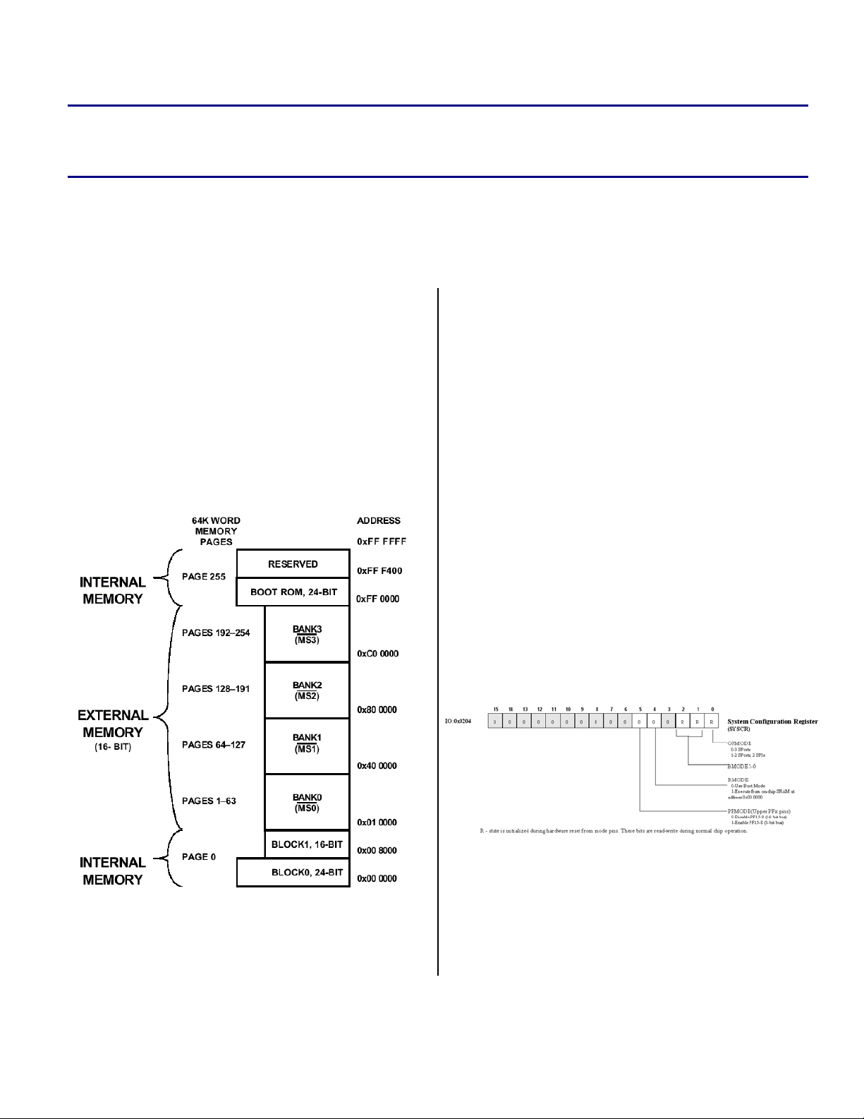
In case of the ADSP-2191, the
Boot Kernel is
located on-chip and stored in a 24-bit wide, 1K
ROM - Figure 1. The starting address of this
boot ROM begins at 0xFF0000 (i.e., the first
location of page 255).
Hardware Reset
s
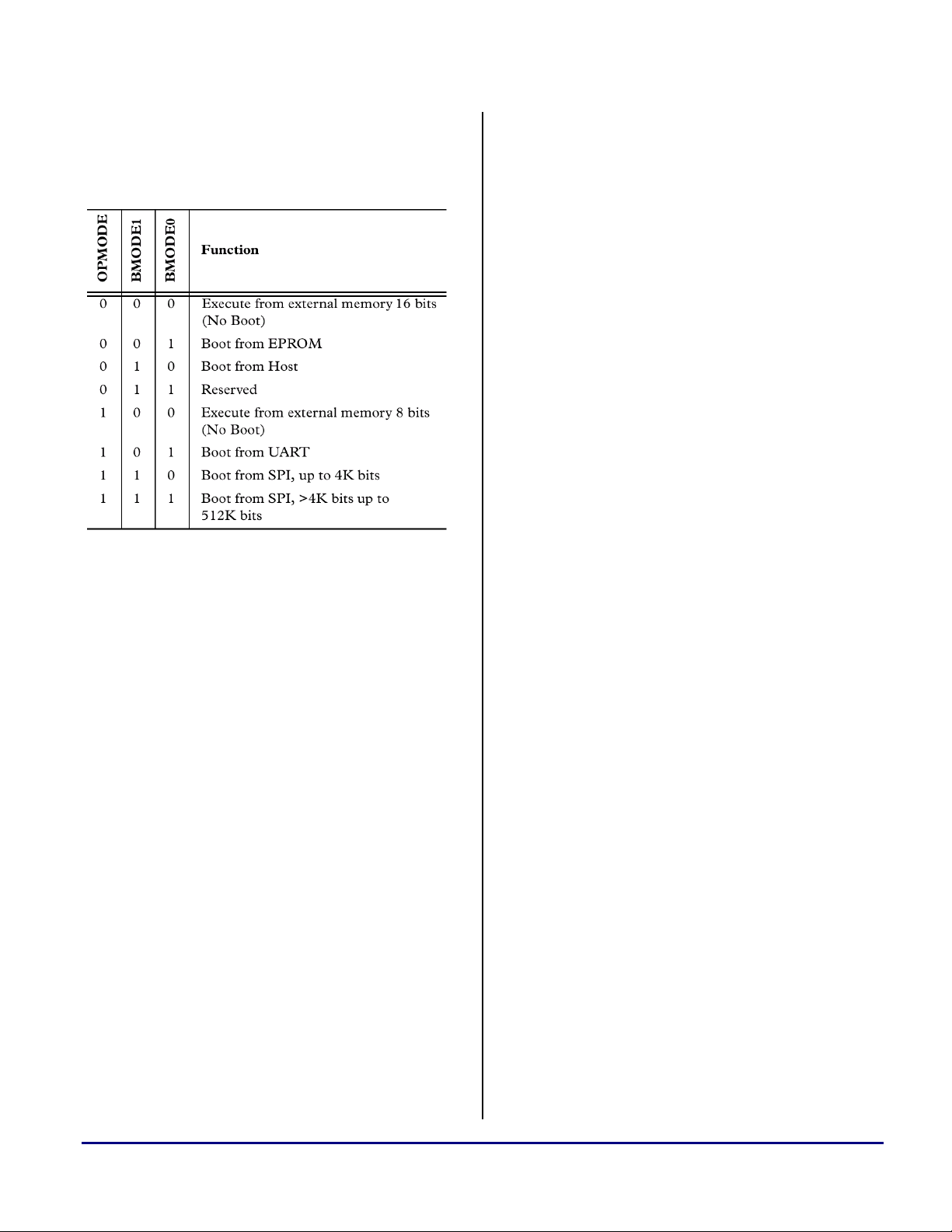
There are three input pins on the ADSP-2191
whose termination state upon hard
/RESET
determines the booting mode – Figure 2. The
state of these three pins (
BMODE1) are sampled on the rising edge of
/RESET and are captured into the corresponding
bits (0,1,and 2) of the
(SYSCR –IO:0x204)
.
OPMODE, BMODE0 and
System Configuration Register
Figure 2 SYSCR Register
Figure 1 Loader Kernel BOOT ROM at Page 255
This Loader Kernel would then either load in
corresponding
Copyright 2003, Analog Devices, Inc. All rights reserved. Analog Devices assumes no responsibility for customer product design or the use or application of
customers’ products or for any infringements of patents or rights of others which may result from Analog Devices assistance. All trademarks and logos are property
of their respective holders. Information furnished by Analog Devices Applications and Development Tools Engineers is believed to be accurate and reliable, however
no responsibility is assumed by Analog Devices regarding technical accuracy and topicality of the content provided in Analog Devices’ Engineer-to-Engineer Notes.
Page Loaders (as in the ADSP-
Note that for pinout requirements, the OPMODE
pin has a dual role (boot-mode-select during a
hard
/RESET and also in determining whether the
third SPORT on the DSP functions as SPORT2
or SPI1). Hence it is possible that an application
Page 2
a
might require the OPMODE to be different at
runtime than it is at hard
the
Boot Kernel has the ability to set it accordingly
/RESET. In such cases,
at the end of the boot process.
Figure 3 Selectable Boot Modes
The OPMODE bit can be changed in
L
software at anytime during run-time
provided the corresponding peripherals
are disabled at that time.
Software Reset
When the ADSP-2191 comes out of /RESET,
program control jumps to 0xFF0000 and begins
execution of the internal boot ROM code. In the
case of a software
/RESET, program control will
either jump to 0xFF0000 or to 0x000000,
depending on the state of bit 4 of the
Configuration Register (NXTSCR - IO:0x203)
Next System
. If this bit
is a 0, program flow jumps to 0xFF0000. If it is a
1, program flow jumps to 0x000000, which is
equivalent to doing
Software /RESET without a Boot.
Boot Modes
Following a /RESET, the first operation performed
by the
Configuration Register (SYSCR, IO 0x00204) and
determine the means from which the DSP is set
up to boot (
Boot Kernel is to read the SYSTEM
BMODE 0/1 and OPMODE).
In the event that the DSP is configured to boot,
the first operation performed by the
to read in the first word of the
Boot Kernel is
Boot Stream. This
“control” word will contain information on the
rest of the boot. This transfer will be done in the
default modes that the DSP comes up with (e.g.,
8-bit external to 16-bit internal packing mode in
case of the EMI, with maximum wait states and
base clock divisor).
If it is determined that the DSP is not going to
boot in a program, but instead run a users
program from 8-bit or 16-bit external memory,
the boot ROM routine will set up the
Memory Interface
and the External Access Bridge
External
register for the desired packing mode (8-bit
external to 24-bit internal or 16-bit-external-to24-bit internal), and then jump to the first
location of external memory (0x10000), where
the user program will be executed.
SPI Booting
If SPI booting is selected, the Boot Kernel will set
up SPI0 as master. It is set to receive 8-bit words,
MS-Bit first, SCLK = HCLK/60, with an activelow serial clock to be compatible with commonly
available serial EEPROMS.
The DMA engine is not used at all, but rather all
the data is read in through core reads a byte at a
time and packed internally by the
Boot Kernel.
Please note, that there is a dedicated application
note available. EE-145 describes SPI booting in
detail [4].
UART Booting
In the case of UART boot, the Boot Kernel begins
by first running an
to determine the baud-rate of the external UART
device. Once the baud-rate has been determined,
the
Boot Kernel will proceed with the rest of boot.
For
auto-baud detection the ADSP-2191 expects
the character 0xAA to be transmitted by an
external device. The
auto-baud routine using a timer
Boot Kernel initializes Timer
Booting the ADSP-2191/95/96 DSPs (EE-131) Page 2 of 9
Page 3
a
0 in order to capture an active high pulse at the
RX pin. Therefore Bit 1 of the
evaluated in order to determine the UART bit
rate.
Please be aware that just the width of
L
Once Bit 1 has been captured and the bit rate has
been determined, the UART loader kernel replies
immediately the bytes
corresponding to “OK” in ASCII. Due to a chip
anomaly the
transmitted [3]. This depends on the bit rate and
DSP clock.
Bit 1 is captured, it is not sampled like
during normal UART operation. It is
obvious that missing signal integrity
and unsymmetrical raising/falling edges
may force the auto-baud detection to
fail. Especially at higher bit rates this
can become a serious issue. In practice
bit rates above 9600bps are not
recommended for booting if the UART
signal passes standard EIA-232 cables
and level shifters.
0x4F (“O”) may or may not be
0xAA character is
0x4F and 0x4B
Users of VisualDSP++™ 2.0 without
L
There also exists a rare case that requires this
first wait-state byte again in order to correct the
alignment of the entire boot stream. This is the
case when the bit rate used during booting gets
close to the default bit rate of the DSP
(HCLK/16). While listening to the auto-baud
character
buffer normally captures two bytes.
Service Pack 1 need to remove this first
byte manually from the loader file.
0xAA, the two-depth UART receive
The resulting UART bit rate will always
L
The external device can now begin transmitting
the boot file, byte by byte without caring about
any protocol. The DSP is fast enough to process
the data in time in any usual configuration. The
Boot Kernel does not transmit any further
characters by itself. Therefore, it is very common
that the loaded application finalizes the boot
procedure by transmitting any acknowledge as
soon as it has been started. Note that the loader
kernel does not alter the UART settings (neither
the
booting.
UART boot files have basically the same format
like others. Only the first byte of the boot stream,
that normally holds the wait-state information, is
removed in case of UART booting.
be a fraction of the peripheral clock
HCLK. With low HCLK frequencies
(bypass mode) and high bit rates the
likelihood of bit errors may increase.
LCR register nor the divisor latch) after
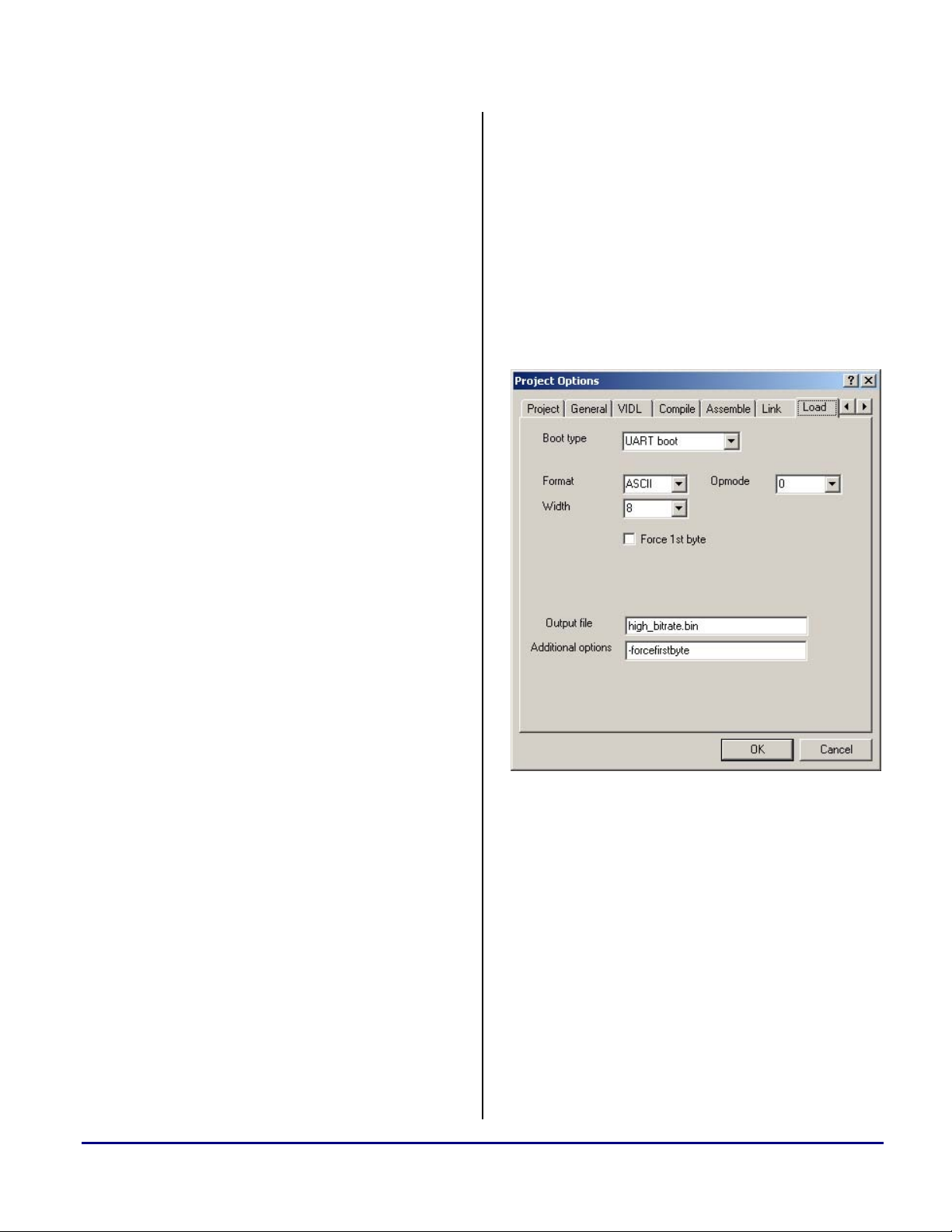
Figure 4 UART Load Property Page
In unusual applications where in either the DSP
clock is very low or the UART bit rate is very
high, the receive buffer may hold only one byte
after auto-baud detection. Therefore new
versions of the VisualDSP++ loader utility
remove the wait-state byte by default in case of
UART booting but provide a new command line
switch
the boot stream alignment in the special case
described above. Within the Load property page
of the
switch in the
Figure 4.
-forcefirstbyte. This switch corrects
Projects Options menu you can specify this
Additional options field like shown in
Booting the ADSP-2191/95/96 DSPs (EE-131) Page 3 of 9
Page 4

a
Although external 8-bit SRAM may be booted,
EMI settings such as bus width and wait states
cannot be controlled in UART boot mode.
Booting of 16-bit off-chip memory is not
supported, therefore.
Host Booting
If booting via a Host processor, the Boot Kernel
will relocate the Interrupt vector location to page
0 of memory. It will then sit in a loop polling the
Semaphore A register (IO:0x1CFC), waiting for a Host
Processor to write to it. The Host processor has
the responsibility of loading the code and data
into the DSP.
The ADSP-2191 can be booted from either an 8bit, 16-bit, or 32-bit Host processor. In the case
of booting from a 32-bit Host, the Host must
send data on the 16 least significant data lines
(right-justified). The Host boot is configured to
always use little-endian format, as this is the
default that the Host port comes up in.
the /BMS strobe. It sets up the corresponding
system and control registers accordingly and
starts reading from logical DSP address
0x80.0000 (aliasing to EPROM address
0x00.0000). The first two words determine EMI
bus width and wait states.
For /BMS to /MSx boot sequences, the
L
L
The
block to read in the first header of the boot
stream via DMA.
EMI bus widths must match. This
means you cannot boot 8-bit
from a 16-bit
boot 16-bit
/BMS.
The Loader Kernel sets the E_WMS field in
the
BMSCTL register to binary 11. This
enables the EMI access to be
abbreviated by the ACKnowledge
signal before the wait states expire.
Therefore pull
Boot Kernel will then set up a DMA transfer
/BMS. Also, you cannot
/MSx space from an 8-bit
ACK down if not used.
/MSx space
After the Host processor has finished loading the
ADSP-2191, it indicates this by writing a “1” to
the
Semaphore A Register (IO:0x1CFC). The Boot
Kernel
will then exit the polling loop and transfers
program control to the first location of page 0.
Example: If the representation of decimal
number 1025 is 00000100 00000001, the
following figure describes big and little endian
representation of the number.
Big-Endian
Address
00
01
02
03
Table 1 Big Endian versus Little Endian
representation of
1025
-
00000100
00000001
Little-Endian
representation of
1025
00000001
00000100
-
-
EMI Booting
If booting via the EMI, the Loader Kernel
expects an EPROM or Flash device connected to
After a header is read in, the
parse the header and set up another DMA
transfer block to load in the actual data following
this header. While this DMA is in progress, the
Boot Kernel will poll the DMA ownership bit to
determine whether the DMA has completed or
not.
To optimize booting speed, due to the
L
Once a data block has been read/initialized, the
next header is read in, and the process is
repeated. This process repeats for all the blocks
that need to be transferred.
The last block to be read/initialized will be the
final DM block. This final block will not be loaded
with DMA (even if it is larger than 32 words),
but will rather be direct core accesses. The
overhead of setting up and kicking off
DMA sequence, if the size of a data
block following the header is less than
32 words, that block is read/initialized
using core-driven direct reads as
opposed to using DMA.
Boot Kernel will
Booting the ADSP-2191/95/96 DSPs (EE-131) Page 4 of 9
Page 5

a
N
purpose of the final block is to clean up the
scratch area used by the Boot Loader for storing
temporary DMA control blocks and variables.
When it has completed loading in the last piece
of data, the interrupt service routine performs
some housecleaning and transfers program
control to the first location of page 0.
Boot Stream Formats
The boot stream is comprised of a series of
“headers” consisting of 4 words, followed by
optional data blocks for non-zero data. Each
header contains information on the type of data
that immediately follows, the starting address
and the word count. In case of booting via the
SPI or UART, after a header is read in (the
Kernel
will use interrupts and a simple-counter
based loop to determine the number of words to
read in) the
Boot Kernel parses the header and sets
up another counter-based loop to load in the
actual data following this header. These transfers
are interrupt-driven.
Boot
belong to EMI boot space only. The ADSP2191/95/96
checksum error detection.
Boot Kernel does not support
Following the Control word is the regular boot
stream, i.e., a series of “headers” and data
payloads or “blocks”, with each header
optionally followed by a corresponding block of
data.
Control Words<Wait State Information,
EPROM/SPI Width>
16-bit field
Flag <PM/DM/Final PM/Final DM>
16-bit field
<24-bit Starting Address>
32-bit field (24-bit padded to yield 32-bits)
<16-bit Word Count>
16-bit field
<Data Word>
16-bit field if 16-bit data
32-bit field if 24-bit EMI data
24-bit field if 24-bit SPI/UART data
<Data Word>
H
e
a
d
e
r
Data
Block
The first word in the boot-stream is a Control
word that applies to all booting formats, with the
exception of Host boot and No-Boot. Individual
bits within this word are set or cleared based on
the method of booting and specific command line
options specified by the user and loader utility.
Note that some bits are reserved for future use.
Figure 5 Bit configurations of Control word
This is a 16-bit field that contains among other
things, information on the number of Wait States
and the Data Width, External port or serial
EEPROM. Wait-state and Clock-divider settings
:
:
Flag
<Starting Address>
<Word Count>
<Data Word>
<Data Word>
:
Table 2 Boot stream format
ext
Header
Each header will consist of four 16-bit words.
Details on the header are given below:
The first word of a header is a 16-bit field
consisting of a flag that indicates whether the
block of data to follow is either a 24-bit or 16-bit
payload or zero-initialized data. The flag also
uniquely identifies the last block that needs to be
transferred. Table 1 lists the Flags with
associated function.
Booting the ADSP-2191/95/96 DSPs (EE-131) Page 5 of 9
Page 6

a
While data blocks always have to follow a
header, data blocks do not follow headers
indicate regions of memory that are to be “zerofilled”.
Flag Values Payload Type
0x00 24-bit data/PM
0x01 16-bit data/DM
0x02 Final 24 bit/PM
0x03 Final 16 bit/DM
0x04 zero-init 24 bit/PM
0x05 zero-init 16 bit/DM
0x06 zero-init Final 24 bit/PM
0x07 zero-init Final 16 bit/DM
0x08 thru 0xFF
Table 3 Boot Flags
Reserved
does not support 8-bit transfers (internal packing
has to be one of either 8-16, or 8-24, or 16-16, or
16-24 bits), to load in the 4-word header, the
word count needs to be set to 4 in either case.
D15 – D8 D7 – D0
Not used Wait states
Not used Width
Not used LSB of Flag
Not used MSB of Flag
Not used LSB of Addr
Not used 8-15 of Addr
Not used MSB of Addr
Not used 00
Not used LSB of Wordcount
Not used MSB of Wordcount
The second word of a header (16-bit field)
contains the lower 16 bits of the 24-bit start
address to begin loading the data (destination).
The first octet will be the 8 LSBs, followed by
the next most significant bits (8-15), and so on.
The third word (16-bit field) contains the uppermost 8 bits of the 24-bit destination address,
padded (suffixed) with a byte of zeros.
The fourth word (16-bit field) contains the word
count of the payload. As with the address, the
first octet will be the 8 LSBs, the second octet
Not used 00
Not used 00
Not used LSB of Word
Not used MSB of Word
: :
Not used 00
Not used LSB of Data Word
Not used 8-15 of Data Word
Not used MSB of Data Word
alignment
bytes
16-bit
data word
24-bit
data word
will be the 8 MSBs.
These four words constitute the “header”.
Following the header is the data block. 16-bit
data is sent in a 16-bit field while 24-bit data is
sent in a 32-bit field.
24-bit data is represented differently in
L
the boot stream from 24-bit addresses.
32-bit data will be transmitted the way:
a byte of zeros, bits 0-7, followed by
bits 8-15, and finally bits 16-24.
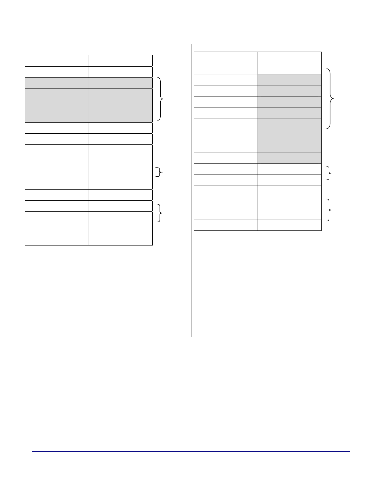
Table 4 EMI boot stream format (8-bit)
There are two alignment bytes inserted after the
first header in the 8-bit EPROM boot file. This
ensures that subsequent data is aligned at a 32-bit
border as required by 24-bit DMA. In addition it
is ensured all further headers are aligned
properly. If the word count of 16-bit streams is
an odd number, two additional alignment bytes
are appended. 16-bit EPROM files don’t require
these alignment bytes.
Table 4 and Table 5 show example boot streams
when booting via the EMI, from an 8-bit device
and a 16-bit device respectively. Boot stream
format is in little endian. Since the DMA engine
Booting the ADSP-2191/95/96 DSPs (EE-131) Page 6 of 9
H
e
a
d
e
r
Page 7
a
D15 – D8 D7 – D0
00 Wait states
00 Width
MSB of Flag LSB of Flag
15-8 of Addr LSB of Addr
00 MSB of Addr
MSB of Wordcount LSB of Wordcount
MSB of Word LSB of Word
: :
: :
MSB of Word LSB of Word
LSB of Data Word 00
MSB of Data Word 15-8 of Word
H
e
a
d
e
r
16-bit
data
word
24-bit
data
word
D15 – D8 D7 – D0
Not used Wait states
Not used Width
Not used LSB of Flag
Not used MSB of Flag
Not used LSB of Addr
Not used 8-15 of Addr
Not used MSB of Addr
Not used 00
Not used LSB of Wordcount
Not used MSB of Wordcount
Not used LSB of Word
Not used MSB of Word
: :
Not used LSB of Data Word
Not used 8-15 of Data Word
Not used MSB of Data Word
H
e
a
d
e
16-bit data
word
24-bit data
word
Table 5 EMI boot stream format (16-bit)
Unlike EMI booting, 24-bit data is now
represented as three bytes. Table 6 shows the
boot stream format when booting via the SPI or
UART.
Table 6 UART and SPI boot stream format (8-bit)
The last block to be read/initialized will be the
“final DM” block. This final block is also read in
with direct core accesses. Following the final
transfer, the interrupt service routine performs
some housecleaning and transfers program
control to the first location of page 0.
Booting the ADSP-2191/95/96 DSPs (EE-131) Page 7 of 9
Page 8

a
Booting the ADSP-2191/95/96 DSPs (EE-131) Page 8 of 9
Page 9

References
[1] ADSP-2191 DSP Hardware Reference,
July 2001, Analog Devices Inc.
[2] ADSP-2191 DSP Data Sheet, Rev. 0,
April 2002, Analog Devices Inc.
[3] ADSP-2191/95/96 DSP Anomaly List for Revision 0.2,
October 2002, Analog Devices Inc.
[4] SPI Booting of the ADSP-2191 using the Atmel AD25020N (EE-145)
September 2001, Analog Devices Inc.
[5] Advanced EPROM Boot and No-boot Scenarios with ADSP-219x DSPs (EE-164),
April 2003, Analog Devices Inc.
Document History
Version Description
a
April 14, 2003 Title has been changed to cover ADSP-2195 and ADSP-2196 DSPs, too.
Explained alignment bytes in EPROM boot stream.
More mark-ups in section UART Booting.
November 12, 2001 UART Section reworded
May 03, 2001 Initial Release of “Booting The ADSP-2191”
Booting the ADSP-2191/95/96 DSPs (EE-131) Page 9 of 9
 Loading...