

Evaluation Board User Guide
UG-072
CPLD
ANALOG
INPUTS
ANALOG
OUTPUTS
S/PDIF
RECEIVER AND
TRANSMITTER
POWER SUPPLY
REGULATION
USB
INTERFACE
MULTI-
PURPOSE
PIN
INTERFACE
ADAU1401A
08697-001
One Technology Way • P.O. Box 9106 • Norwood, MA 02062-9106, U.S.A. • Tel: 781.329.4700 • Fax: 781.461.3113 • www.analog.com
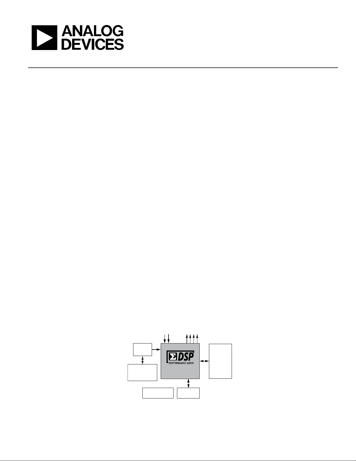
ADAU1401A, ADAU1401, ADAU1701, and ADAU1702 SigmaDSP Evaluation Board
GENERAL DESCRIPTION
The EVA L-ADAU1401AEBZ is a platform that operates all of
the ADAU1401A’s functions with a full range of analog and
digital inputs and outputs. Digital I/O connections are available
in both S/PDIF and 3-wire serial data formats. The DSP is
controlled by the SigmaStudio™ software, which interfaces to
the board through a USB connection. This evaluation board is
powered by a single supply, which is regulated to the proper
voltages on the board. The PCB is in a 6” × 6” 4-layer design,
with a single ground plane and a single power plane on the
inner layers.
The ADAU1401A can be controlled via the USBi interface
control board connected to the I
interface. On-board self-boot EEPROM is included for
operating the board independently of the SigmaStudio software.
Push-buttons, LEDs, potentiometers, and other interface
options on the included GPIO board can be connected to the
evaluation board to enable GPIO control.
The EVA L-ADAU1401AEBZ can also be used for evaluation of
the pin-compatible ADAU1701 and ADAU1702 SigmaDSP®s.
The differences between the ADAU1401A, ADAU1401,
ADAU1701, and ADAU1702 are:
• The ADAU1701, ADAU1401A, and ADAU1401 have 1024
program RAM locations, while the ADAU1702 has 512
program RAM locations.
• The ADAU1701 has 2k words of data memory, while the
ADAU1702 has 0.5k words of data memory.
2
C/SPI communications
• The ADAU1401A is qualified over the automotive
temperature range (−40°C to +105°C), while the
ADAU1701 and ADAU1702 are qualified over the
consumer temperature range (0°C to 70°C).
• The ADAU1401 is an older revision of the ADAU1401A.
The ADAU1401A is recommended for new designs.
PACKAGE CONTENTS
EVAL-ADAU1401AEBZ evaluation board
GPIO control board
USBi board
Universal power supply
Mini-USB cable
Evaluation board/software quick-start guide, including a
download link for the SigmaStudio tools
OTHER SUPPORTING DOCUMENTATION
When using this evaluation board, refer also to the following
documentation available at www.analog.com:
• ADAU1401A, ADAU1401, ADAU1701, ADAU1702 data
sheets
• AN-923 Application Note, Designing a System Using the
ADAU1701/ ADAU1702 in Self-Boot Mode
• AN-951 Application Note, Using Hardware Controls with
SigmaDSP GPIO Pins
• AN-1006 Application Note, Using t h e E VA L-ADUSB2EBZ
• SigmaStudio help file (included with the software)
PLEASE SEE THE LAST PAGE FOR AN IMPORTANT
WARNING AND LEGAL TERMS AND CONDITI ONS.
EVALUATION BOARD BLOCK DIAGRAM
Figure 1.
Rev. A | Page 1 of 20

UG-072 Evaluation Board User Guide
TABLE OF CONTENTS
General Description ......................................................................... 1
Package Contents .............................................................................. 1
Other Supporting Documentation ................................................. 1
Evaluation Board Block Diagram ................................................... 1
Revision History ............................................................................... 2
Quick Start Setup .............................................................................. 3
Preparing for the First Use .......................................................... 3
SigmaStudio Software Installation ............................................. 3
Powering up the Board ................................................................ 3
Hardware Setup—USBi ............................................................... 3
Connecting the Audio Cables ..................................................... 3
Switch and Jumper Settings ......................................................... 3
Your First SigmaStudio Project—EQ and Volume Control .... 4
Extended Setup ................................................................................. 5
Power Supply ................................................................................. 5
Digital Audio Inputs and Outputs ............................................. 5
Analog Audio Inputs and Outputs ............................................. 5
Master Clock Settings ...................................................................5
Control Interface ...........................................................................5
Switch and Jumper Functions ......................................................6
Rotary Switch Settings ..................................................................6
IC Functions ...................................................................................7
LED Functions ...............................................................................7
Reset ................................................................................................7
Self-Boot .........................................................................................7
Typical Setups ....................................................................................8
All Setups ........................................................................................8
Analog Input and Analog Output ...............................................8
S/PDIF Input and S/PDIF output ................................................8
Using The GPIO Board.....................................................................9
Evaluation Board Schematics ........................................................ 10
GPIO Interface Board Schematics ............................................... 17
Evaluation Board PCB Silkscreen Drawing ................................ 19
REVISION HISTORY
2/12—Rev. 0 to Rev. A
Added ADAU1401A .......................................................... Universal
Changed EVAL-ADAU1401EBZ to
EVA L-ADAU1401AEBZ .................................................... Universal
2/10—Revision 0: Initial Version
Rev. A | Page 2 of 20
Evaluation Board User Guide UG-072
08697-002
QUICK START SETUP
PREPARING FOR THE FIRST USE
To get started, use the following steps:
1. Install the SigmaStudio software.
2. Plug in the USBi.
3. Power up the board.
4. Connect the audio cables.
5. Set the switches and jumpers.
SIGMASTUDIO SOFTWARE INSTALLATION
1. Download the SigmaStudio.zip file from
http://www.analog.com/sigmastudiodownload and extract
the files to your PC. The key for the download is provided
in the box with the evaluation board.
2. Install Microsoft® .net Framework V 3.5. If you do not
already have it installed, this can be downloaded from the
Microsoft website.
3. Install SigmaStudio by double-clicking setup.exe and
following the prompts. A computer restart is not required.
POWERING UP THE BOARD
The board is powered from the included 6 V dc power supply
connected to J14. The power indicator LED, D11, should be lit.
HARDWARE SETUP—USBi
1. Plug in a power supply to the power jack, J14, of the EVA L -
ADAU1401AEBZ evaluation board.
2. Plug the USBi into the USB port of the PC using the mini-
USB cable.
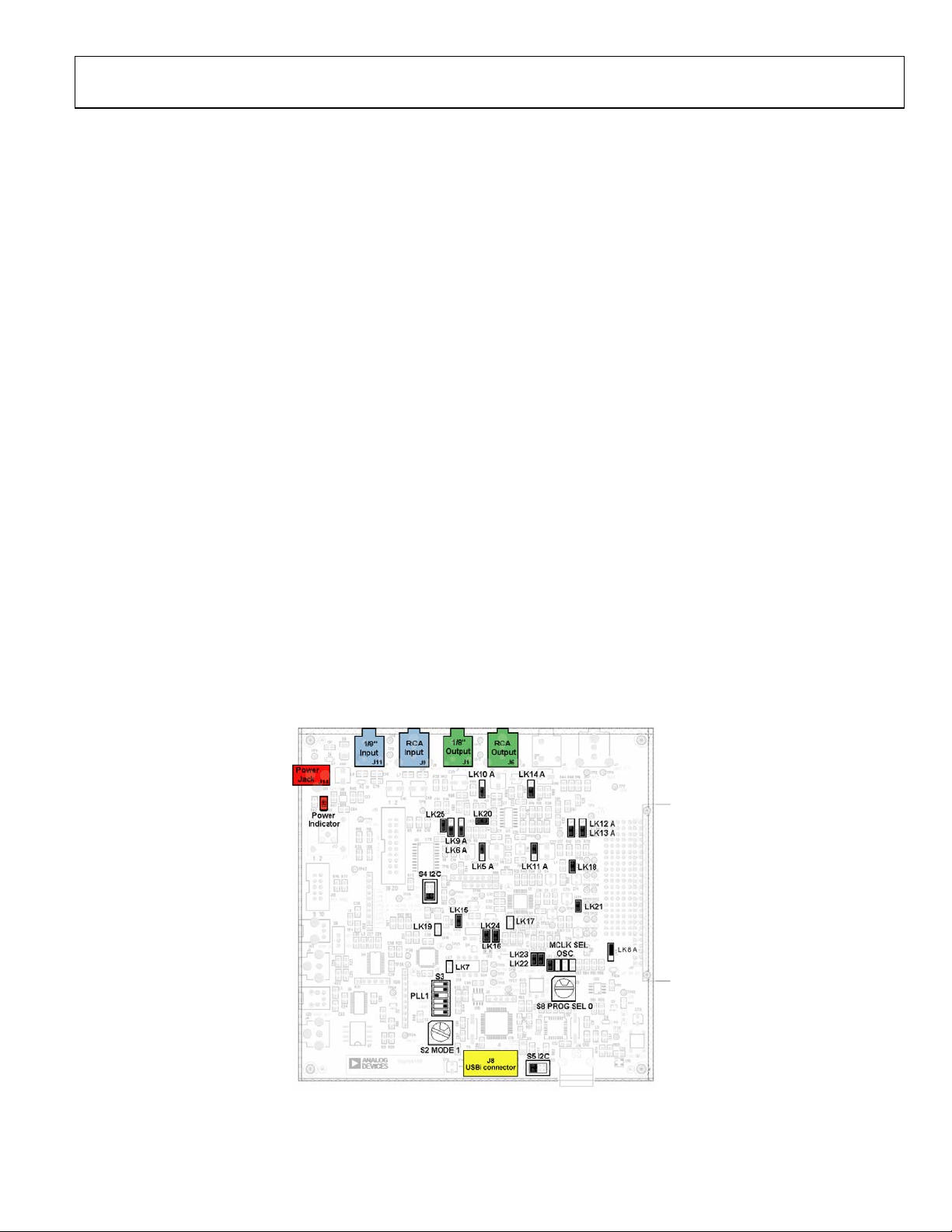
3. Plug the USBi into the control port on the evaluation board
(marked yellow in Figure 2).
4. Connect the USB cable to the computer and to the USBi.
5. When prompted for drivers, use the following options:
• Choose Install from a list or a specific location.
• Choose Search for the best driver in these locations.
• Check the box for Include this location in the search.
• The USBi driver is located in C:\Program Files\
Analog Devices Inc\Sigma Studio\USB drivers, click
Next.
• If prompted to choose a driver, select CyUSB.sys.
• In XP only, click Continue Anyway if a prompt
appears indicating the software has not passed
Windows Logo testing.
6. Make sure that Switch S4 and Switch S5 of the E VAL -
ADAU1401AEBZ are set to the I2C position.
CONNECTING THE AUDIO CABLES
For this example, set up the board to have stereo analog inputs
and stereo analog outputs. To do so, use the following steps:
1. Connect the audio source to the IN 0/IN 1 jacks on the top
of the board (marked blue in Figure 2), using 3.5 mm (⅛”)
cables.
2. Connect the OUT 0/OUT 1 jacks on the top of the board
(marked green in
headphones.
Figure 2) to your speakers or
SWITCH AND JUMPER SETTINGS
To configure the board for stereo analog input and output, make
sure the switches and jumpers are set as indicated in Figure 2.
Figure 2. Evaluation Board Setup and Configuration
Rev. A | Page 3 of 20
UG-072 Evaluation Board User Guide
08697-003
08697-004
YOUR FIRST SIGMASTUDIO PROJECT—EQ AND VOLUME CONTROL
The following is a procedure for building your first project in
SigmaStudio and running it on the evaluation board. This
procedure creates a simple design that creates a volume control
and five-band EQ on a stereo input signal.
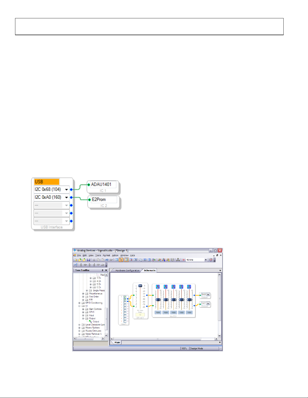
1. Create a new project. SigmaStudio opens to the Hardware
Configuration Tab.
2. Drag a SigmaDSP IC (ADAU1401A, ADAU1701,
ADAU1702, or ADAU1401), E2Prom, and a USBi cell
into the blank white space.
Note: If you are using a processor other than the
ADAU1401A, (for example, ADAU1701 or ADAU1702),
drag that processor out instead.
3. Connect the USBi cell to the ADAU1401A (or other
SigmaDSP) cell by clicking and dragging from the top blue
output pin to the green input pin.
4. Connect the second USBi blue output pin to the green
input pin on the E2Prom cell.
The screen should appear as it does in Figure 3.
5. Click the Schematic tab at the top of the screen.
6. In the Tree To ol Bo x section, expand the IO > Input. Click
and drag an Input cell to the work area.
7. Similarly, expand Filters > Second Order > Double
Precision > 2 Ch and click and drag Medium Size Eq to
the work area.
8. Right-click the general (second-order) cell labeled Gen
Filter1.
9. Click Grow Algorithm > 1. 2 Channel – Double
Precision > 4. This creates a five-band equalizer (EQ).
Each band’s general filter settings can be modified by
clicking the blue boxes on the cell.
10. Expand Volume Controls > Adjustable Gain > Shared
Slider > Clickless SW Slew and click and drag Single slew
11. Expand the IO > Output. Click and drag two Output cells
12. For each of the outputs, select a DAC output by clicking the
pull-down box. DAC0 and DAC1 are left and right
outputs, 0 and 1, from the ADAU1401A (output on J1 as
marked in green in Figure 2), respectively. DAC2 and
DAC3 are left and right channel, respectively for the
second stereo line output (J3 on the board).
13. Connect all the cells as depicted in Figure 4.
14. Make sure the board is powered and connected to the PC.
Click the Link-Compile-Download button in the
SigmaStudio toolbar, or select Link-Compile-Download
from the Action menu.
15. If the project compiled without error, you will be in Ready-
Download mode.
Your screen should now appear as it does in Figure 4.
16. Play your audio source; audio should now be available.
Move the volume control and filter sliders and hear the
Figure 3. Hardware Configuration Tab
Figure 4. Schematic Tab, Full Design
effect on the output audio in real time.
Rev. A | Page 4 of 20

Evaluation Board User Guide UG-072
EXTENDED SETUP
POWER SUPPLY
The evaluation board is powered by a single supply through
Connector J14. The voltage on J14 should be 6 V dc to 9 V dc
with the ability to source at least 200 mA. The tip of the power
supply connector should be the positive voltage. This single
supply is regulated to 3.3 V for both the analog and digital
planes. The ADAU1401A generates 1.8 V from the 3.3 V supply
using its integrated regulator.
DIGITAL AUDIO INPUTS AND OUTPUTS
Digital signals can be connected to the board in two different
formats. The evaluation board can input or output a standard
2-channel S/PDIF stream. These I/Os can be either electrical (J5
and J4) or optical (U13 and U29). The S/PDIF I/O streams are
connected to the SDATA_IN0 and SDATA_OUT0 serial data
ports and are active according to specific switch settings on S2.
The copy protection bit on the S/PDIF transmitter is set; therefore,
audio devices, such as digital recorders, may ignore the data
output from the evaluation board.
PCM digital audio data can also be interfaced to the ADAU1401A.
This data is connected to the ADAU1401A through the GPIO
interface board that is connected to J12. Input Header J3 and
Output Header J2 can connect to external ADCs, DACs, and
codecs with an I
stream. Master clock, left/right clock, and bit clock connections
are also on these headers.
Up to four stereo audio signals can be input or output on each
of these headers. These signals, when selected by the rotary
mode switches, interface directly to the serial data ports of the
ADAU1401A. These headers also serve as the I/Os for the
multi-channel TDM streams.
2
S, left-justified, right-justified, or TDM data
MASTER CLOCK SETTINGS
The master clock connection of the ADAU1401A is set with
Jumper LK1 to Jumper LK4. These allow the user to select as a
source either the on-board oscillator connected to an external
crystal (OSC), the S/PDIF receiver’s master clock output (DIR),
an external clock from J12 (EXT), or a dedicated clock connection
on a BNC connector, J13 (BNC). If any setting other than OSC
is chosen, then disconnect Jumper LK16, which couples the
oscillator circuit of the ADAU1401A to the crystal. If this
jumper is not removed, there could be two clocks on the PCB
running at very close frequencies. These clocks could easily cause
serious performance degradation on the converters of the
ADAU1401A.
CONTROL INTERFACE
J16 is the connection for the USBi. The USBi is used to send I2C
and SPI control data to the ADAU1401A on the evaluation board.
This provides a real-time programming and tuning connection
to SigmaStudio.
Note that the evaluation board also includes footprints for an
obsolete USB interface using Connector J16. This section of the
board has been replaced by the USBi’s functionality.
ANALOG AUDIO INPUTS AND OUTPUTS
The evaluation board can input two analog audio signals and
can output four signals using the converters of the
ADAU1401A. The full-scale input voltage is 2.0 V rms and the
full-scale output voltage is 0.9 V rms.
Mini-jack J11 is the input to the ADCs. Mini-jack J1 and Minijack J3 are the DAC output connectors. The output is low-pass
filtered with either an active anti-image filter using a U3 op amp
or a passive RC filter. The active filters’ −3 dB cutoff frequency
is 100 kHz and has an approximate third-order Bessel (linear
phase) response.
Rev. A | Page 5 of 20
UG-072 Evaluation Board User Guide
S2
Signal routing mode select.
S3-1
Sets SELFBOOT.
S3-2
Sets PLL_MODE0.
S3-3
Sets PLL_MODE1.
S3-4
Sets ADDR0.
S3-6
Reserved—set low.
S4
Sets I2C or SPI connection to the ADAU1401A.
S5
USBi control connector—I2C (left) or SPI (right).
S6
Selects between RCA and optical S/PDIF input.
S7
Unused.
LK1 to LK4
Selects which master clock signal is sent to the
LK5 to LK6,
LK9 to LK14
Connects the DAC outputs to active (A) or passive
(B) filters.
LK8
Selects 3.3 V or 5 V power connected to GPIO
LK15
Connects the 1.8 V output of the regulator
transistor to DVDD of the ADAU1401A.
LK17
Connects/disconnects MCLK output to external
audio performance of the board.
LK18
Connects 3.3 V to AVDD of the ADAU1401A.
LK20
Connects 3.3 V to the AD8608 op amp.
LK21
Connects 3.3 V to the IOVDD of the ADAU1401A.
LK25
Connects 3.3 V power to serial data buffer.
Mode
Function
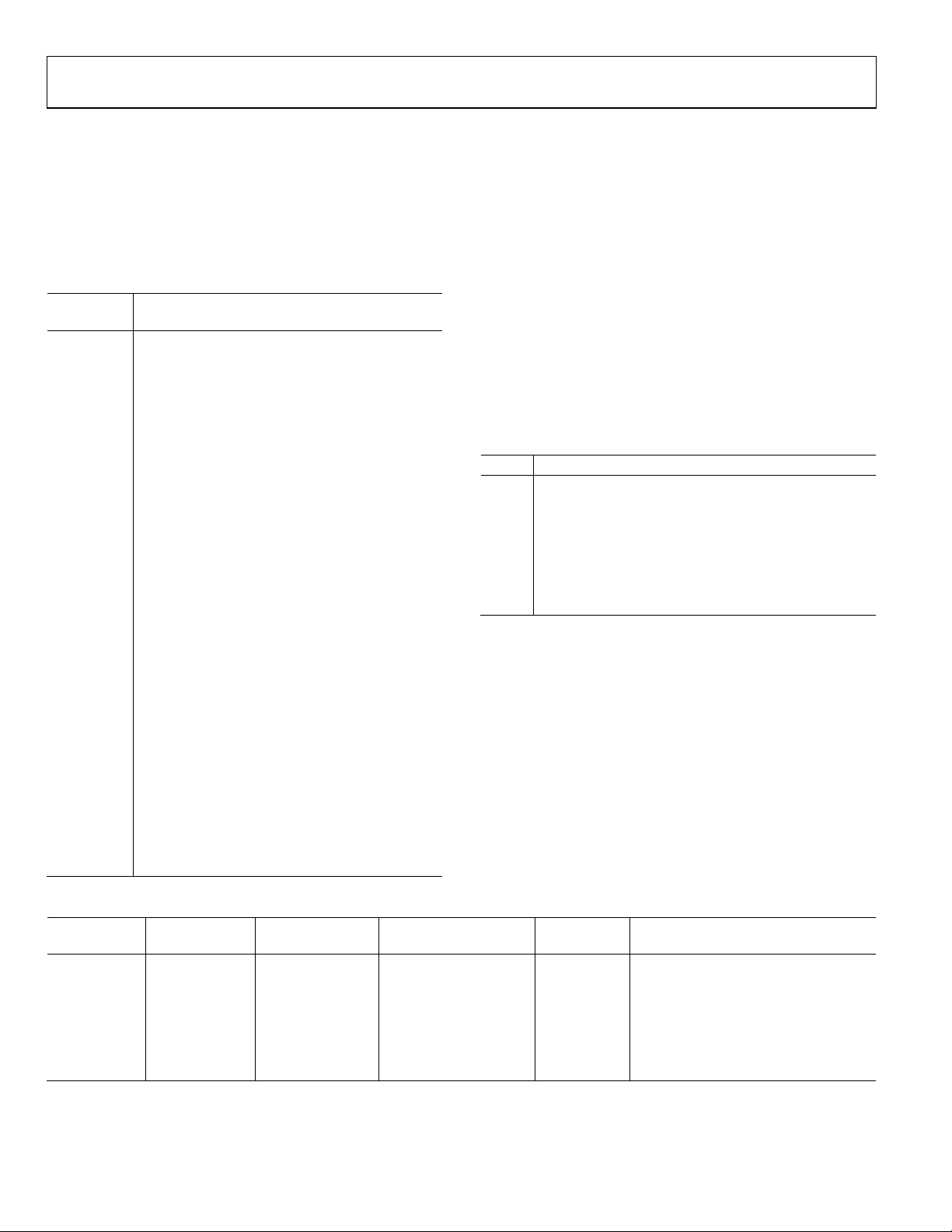
SWITCH AND JUMPER FUNCTIONS
This evaluation board has many switches and jumpers; however,
for most applications, many of these need to be set only once
and can be ignored after that. Ta b l e 1 shows the function of
each jumper and switch on the evaluation board. For the S3
switch package, logic high (1) is left and logic low (0) is right,
assuming analog connectors are the top of the board.
Table 1. Switches and Jumpers
Reference
Designator
S1 Resets evaluation board.
Function
ROTARY SWITCH SETTINGS
S2 is a hex rotary switch that controls the input and output
signal routing on the evaluation board. The position of this
switch controls which serial data signals and clocks will be
routed to and from the ADAU1401A. Tab l e 3 shows the settings
of Rotary Switch S2. This switch controls the routing of digital
signals to and from the ADAU1701/ADAU1702 (U1) serial
input and output ports. Tabl e 3 indicates which serial data
signals and clocks are sent to each of the four serial data inputs,
as well as to where the output signals of the serial port are
routed. An x in the table indicates that no signal is sent to that
input pin on the ADAU1701/ ADAU1702 in that mode. Switch
Position 4 to Switch Position F are unused.
The functions in Ta b l e 2 are available for each of the modes in
Tabl e 3.
S3-5 Sets ADDR1.
S8 Unused.
PLL of the ADAU1401A.
LK7 Sets the EEPROM write protect pin.
control board.
LK16
LK19 Writeback trigger input.
Connects/disconnects 12.288 MHz crystal from
oscillator circuit of the ADAU1401A.
circuits. Connecting this may degrade the analog
Table 2. S2 Settings
0
1
2
3
Inputs: S/PDIF, analog
Outputs: S/PDIF, analog, serial data (slave)
Inputs: analog, serial data
Outputs: analog, serial data (master or slave)
Inputs: analog, serial data
Outputs: S/PDIF, analog, serial data (master)
Inputs: S/PDIF, analog
Outputs: analog
The multipurpose pins of the ADAU1401A must be set into
serial data I/O modes to use the board’s digital I/O.
Table 3. S2 Settings
SW2 Position SDATA_IN0
0 S/PDIF Rx x
1 x x x x ADAU1401A crystal oscillator
2 External Input 0
3 S/PDIF Rx x x x S/PDIF Rx
4 to F x x x x x
1
x = no signal is sent to the input pin.
1
SDATA_IN1 to
SDATA_IN3
External Input 1 to
External Input 3
SDATA_OUT0 to
SDATA_OUT3 SPDIF Tx Clock Master
External Output 0 to
External Output 3
External Output 0 to
External Output 3
SDATA_OUT0 S/PDIF Rx
SDATA_OUT0 ADAU1401A output
Rev. A | Page 6 of 20

Evaluation Board User Guide UG-072
U14
Self-boot EEPROM: 32 kB × 8 (256 kB)
IC FUNCTIONS
Tabl e 4 explains the function of each IC on the evaluation
board. The Lattice CPLD (U2) is only used for routing signals
on the board and performs no decoding or signal conditioning.
Table 4. IC Functions
Reference
Designator Function
U1 ADAU1401A SigmaDSP audio processor
U2 Lattice M4A3-64/32 CPLD for signal routing
U3
U4 CS8416 S/PDIF receiver
U5 74LVC541 for buffering serial output signals
U6 CS8406 S/PDIF transmitter
U8 ADP3336-3 regulator—3.3 V analog supply
U10 ADM811RART reset generator
U11 Unused
U12 74LVC1G240 inverter
U18 Unused
U19 Unused
U20 Unused
AD8608 quad op amp for analog audio output
buffering
LED FUNCTIONS
D11 indicates that the 3.3 V supply is present through an
external supply.
RESET
The evaluation board can be reset with a push-button switch,
S1. This active-low reset signal is debounced by the ADM811
(U10). This reset signal affects the ADAU1401A and S/PDIF
receiver and transmitter. The board may also be reset by
disconnecting the power. After reset, the ADAU1401A does not
pass audio, and a control port write has to be performed so that
signals are output again.
SELF-BOOT
The self-boot function of the ADAU1401A can be set up on the
evaluation board. This allows the ADAU1401A to boot itself
from EEPROM U14 when it is brought out of reset. The
ADAU1401A is the master on the I
operation; however, another bus master device may take control
afterwards.
The first step in setting up self-boot mode is to load a program
from SigmaStudio into the EEPROM. This is done by using the
Load latest compilation to EEPROM function found by rightclicking on the IC in the Hardware Configuration window.
This should be done while the S3-1 self-boot switch is set low
(right). Note that the jumper should not be on LK7 for this
operation because the EEPROM cannot be write-protected.
After the program is saved, Switch S3-1 can be set high (left),
which sets the ADAU1401A into self-boot mode the next time
it is powered on or reset.
2
C bus during the self-boot
Rev. A | Page 7 of 20

UG-072 Evaluation Board User Guide
LK7, LK19
Jumper off
S3-2
0 (right)
LK17
Connected
TYPICAL SETUPS
ALL SETUPS
The switch and jumper settings in Tabl e 5 are common for all
typical setups described in this user guide.
Table 5. Standard Switch and Jumper Settings
Component Setting
LK15, LK18,
LK20 to LK25
S3-4 0 (right)
S3-5 0 (right)
S4 Down (for default I2C communication)
S5 Left (for default I2C communication)
Jumper on
ANALOG INPUT AND ANALOG OUTPUT
Input comes from the stereo analog inputs to Pin ADC0 and
Pin ADC1 of the ADAU1401A and outputs on the DACs.
Default outputs for the ADC inputs are DAC outputs, VOUT2
and VOUT3.
In this setup, the master clock is generated by the ADAU1401A’s
oscillator connected to a 12.288 MHz crystal. Tab le 6 explains
how the switches and jumpers need to be set up for this mode.
Any component setting not mentioned in Table 6 or in Tabl e 5
can be considered don’t care.
The settings in Ta ble 5 and Ta ble 6 are also appropriate for
using the serial data I/Os.
S/PDIF INPUT AND S/PDIF OUTPUT
Input comes from the stereo S/PDIF receiver to SDATA_IN0
(Pin 10) of the ADAU1401A and outputs on whichever outputs
(SDATA_OUTx) are designated in the SigmaStudio software.
The default output for the input is SDATA_OUT0 (Pin 15).
In this setup, the master clock and serial data clocks are
generated by the CS8416. Tab le 7 explains how the switches
and jumpers need to be set up for this mode. Any component
setting not mentioned in Tabl e 7 can be considered don’t care.
Table 7. Evaluation Board Settings for S/PDIF Input, Analog
and S/PDIF Output
Component Setting
S2 Position 0
S3-2 0 (right)
S3-3 1 (left)
LK1, LK3 to LK4 Disconnected
LK2 Connected
LK5 to LK6,
LK9 to LK14
LK16 Disconnected
A for active filter, and B for passive filter on
DAC outputs
Table 6. Evaluation Board Settings for Analog I/O
Component Setting
S2 Position 1
S3-3 1 (left)
LK1 Connected
LK2 to LK4 Disconnected
LK5 to LK6,
LK9 to LK14
LK16 Connected
LK17 Disconnected
A for active filter, and B for passive filter on
DAC outputs
Rev. A | Page 8 of 20

Evaluation Board User Guide UG-072
MP0
JP9
LED D20
Left
LED D2
Right
USING THE GPIO BOARD
The GPIO board is provided with the EVA L-ADAU1401AEBZ
to connect control and data interfaces to the multipurpose pins
of the ADAU1401A. These controls are broken out on a
separate board from the main evaluation board so that different
configurations beyond what is supplied can be easily connected.
The functions on this board include potentiometers, LEDs,
push buttons, switches, and a rotary encoder.
Tabl e 8 shows how the jumpers should be set to properly route
the controls to the ADAU1401A’s MPx pins. The settings in
Tabl e 8 assume that the board is oriented with a 50-pin
connector, J1, on the left of the board.
Table 8. GPIO Board Jumper Settings and Functions
ADAU1401A Pin Jumper Control Routed to MPx Pin Jumper Setting Notes
Push Button S10 Right Use debounce, signal low on button press
MP1 JP10 LED D21 Left
Push Button S11 Right Use debounce, signal low on button press
MP2 JP11 Rotary encoder Left Must be set to input GPIO, no debounce
Potentiometer R28 Right Read ADC value from Register 0x080A
MP3 JP12 Rotary encoder Left Must be set to input GPIO, no debounce
Potentiometer R30 Right Read ADC value from Register 0x080B
MP4 JP13 Switch S12 Left
Push Button S13 Right Use debounce, signal low on button press
MP5 JP14 Switch S14 Left
Push Button S14 Right Use debounce, signal low on button press
MP6 JP8 Push Button S7 Left Use debounce, signal low on button press
Switch S8 Right
MP7 JP7 Push Button S5 Left Use debounce, signal low on button press
Switch S6 Right
MP8 JP6 Potentiometer R4 Left Read ADC value from Register 0x080C
The 12 jumpers, J3 to J14, should be left on the pins to connect
the MPx pins to the control interfaces. These jumpers should be
removed if the GPIO board is being used to interface serial
audio data to the ADAU1401A through Header J2 and Header
J3. JP1 and JP2 are used to route the serial data ports’ master
clock signals.
The GPIO board uses a Hirose PCN10C-50S-2.54DS connector
to interface to the ADAU1401A evaluation board. Using this
connector and the pinout in Figure 10, any set of controls can
be connected to the multipurpose pins of the ADAU1401A. The
GPIO board is powered through Pin 1 of J12 on the evaluation
board. The voltage supplied to the GPIO board is set with
LK8—3.3 V in Position A or 5.0 V in Position B.
MP9 JP5 Potentiometer R3 Left Read ADC value from Register 0x0809
LED D1 Right
MP10 JP4 Push-button S3 Left Use debounce, signal low on button press
Switch S4 Right
MP11 JP3 Push Button S1 Left Use debounce, signal low on button press
Switch S2 Right
Rev. A | Page 9 of 20

UG-072 Evaluation Board User Guide
08697-005
EVALUATION BOARD SCHEMATICS
Figure 5. ADAU1401A Evaluation Board Schematic
Rev. A | Page 10 of 20

Evaluation Board User Guide UG-072
08697-006
Figure 6. CPLD
Rev. A | Page 11 of 20

UG-072 Evaluation Board User Guide
08697-007
Figure 7. Analog Input and Output Filters
Rev. A | Page 12 of 20

Evaluation Board User Guide UG-072
08697-008
Figure 8. S/PDIF Receiver and Transmitter
Rev. A | Page 13 of 20

UG-072 Evaluation Board User Guide
USBi Heade r
08697-009
Figure 9. Reset Generator and USBi
Rev. A | Page 14 of 20

Evaluation Board User Guide UG-072
08697-010
Figure 10. Multipurpose Pin Interface
Rev. A | Page 15 of 20

UG-072 Evaluation Board User Guide
08697-011
Figure 11. Power Supply
Rev. A | Page 16 of 20

Evaluation Board User Guide UG-072
08697-012
SDATA0_IN
LRCLK_IN
BCLK_IN
SDATA1_IN
SDATA2_IN
SDATA3_IN
SDATA0_OUT
LRCLK_OUT
BCLK_OUT
SDATA1_OUT
SDATA2_OUT
SDATA3_OUT
DVDD selectable as 3V3 or 5V0
on SigmaDSP Board.
Use caution when DVDD=5V0,
damage to Sigma DSP can occur.
12
4681012141618202224
26283032343638404244464850
357
9
1113151719
212325
27
293133
35
373941
43
454749
J1
50-pin
13579
246
8
10
111315
121416
J2
HEADER_16WAY_UNSHROUD
13579
246810
111315
121416
J3
HEADER_16WAY_UNSHROUD
TP1
TP13
TP12
TP11
TP10
TP9 TP8
TP7
TP6
TP5
TP4
TP3 TP2
A B
JP2
3-Jumper
BA
JP1
3-Jumper
+
C2
100uF
K
A
D3
R5
475R
C4
DVDD
DVDD
MP0
MP1
MP2
MP3
MP4
MP5
MP6
MP7
MP8
MP9
MP10
MP11
DVDD
DVDD
MP0
MP1
MP3
MP2
MP4
MP5
MP6
MP7
MP8
MP9
MP10
MP11
MCLK_FROM_DSP
MCLK_TO_DSP
MCLK_TO_DSP
MCLK_FROM_DSP
MCKI
MCKO
DVDD
MCKOMCKI
DVDD
GPIO INTERFACE BOARD SCHEMATICS
Figure 12. GPIO Board Connector
Rev. A | Page 17 of 20

UG-072 Evaluation Board User Guide
08697-013
S10
SPST-NO
S11
SPST-NO
S5
SPST-NO
S7
SPST-NO
S6
SPDT
S8
SPDT
R25
10k0
R27
10k0
R14
10k0
R16
10k0
A B
JP9
3-Jumper
A B
JP10
3-Jumper
S13
SPST-NO
S15
SPST-NO
S12
SPDT
S14
SPDT
R33
10k0
R35
10k0
AB
JP13
3-Jumper
CW
2
1
3
R28
R29
100R
A B
JP11
3-Jumper
CW
2
1
3
R30
R31
100R
AB
JP12
3-Jumper
CW
2
1
3
R3
R10
100R
R1
100R
1
B
2
E
3
C
Q1
D1
Green Diffused
R11
2k00
A B
JP5
3-Jumper
CW
2
1
3
R4
R12
100R
R2
100R
1
B
2
E
3
C
Q2
D2
Green Diffused
R13
2k00
A B
JP6
3-Jumper
S1
SPST-NO
S3
SPST-NO
R7
10k0
R9
10k0
S2
SPDT
S4
SPDT
A B
JP3
3-Jumper
A B
JP4
3-Jumper
A
COM
B
S9
Rotary Encoder
C3
10nF
C5
10nF
R21
10k0
R22
10k0
R20
10k0
R23
10k0
C6
0.10uF
R36
100R
1
B
2
E
3
C
Q3
D20
Green Diffused
R24
2k00
R37
100R
1
B
2
E
3
C
Q4
D21
Green Diffused
R26
2k00
BA
1
2
3
4
JP8
JUMPER34T
BA
1
2
3
4
JP7
JUMPER34T
BA
1
2
3
4
JP14
JUMPER34T
R32
10k0
R34
10k0
R15
10k0
R17
10k0
R6
10k0
R8
10k0
R19
10k0
MP0
MP1
DVDD
6PM7PM
DVDD
5P
M
4PM
DVDD
MP2
DVDD
MP3
DVDD
MP9
DVDD
MP8
DVDDDVDD
01PM11PM
DVDD
MTR_LATC H
MTR_S_IN
MTR_CLK
Figure 13. GPIO Board Controls
Rev. A | Page 18 of 20

Evaluation Board User Guide UG-072
08697-014
EVALUATION BOARD PCB SILKSCREEN DRAWING
Figure 14. Top Layer Silkscreen
Rev. A | Page 19 of 20

UG-072 Evaluation Board User Guide
d FOR EVALUATION PURPOSES ONLY. Customer understands and agrees that the Evaluation Board is provided
any reason. Upon discontinuation of use of the Evaluation Board or termination of this Agreement, Customer agrees to
NOTES
I2C refers to a communications protocol originally developed by Philips Semiconductors (now NXP Semiconductors).
ESD Caution
ESD (electrostatic discharge) sensitive device. Charged devices and circuit boards can discharge without detection. Although this product features patented or proprietar y protection
circuitry, damage may occur on devices subjected to high energy ESD. Therefore, proper ESD precautions should be t aken to avoid performance degradati on or loss of functionality.
Legal Terms and Conditions
By using the evaluation board discussed herein (together with any tools, components documentation or support materials, the “Evaluation Board”), you are agreeing to be bound by the terms and conditions
set forth below (“Agreement”) unless you have purchased the Evaluation Board, in which case the Analog Devices Standard Terms and Conditions of Sale shall govern. Do not use the Evaluation Board until you
have read and agreed to the Agreement. Your use of the Evaluation Board shall signify your acceptance of the Agreement. This Agreement is made by and between you (“Customer”) and Analog Devices, Inc.
(“ADI”), with its principal place of business at One Technology Way, Norwood, MA 02062, USA. Subject to the terms and conditions of the Agreement, ADI hereby grants to Customer a free, limited, personal,
temporary, non-exclusive, non-sublicensable, non-transferable license to use the Evaluation Boar
for the sole and exclusive purpose referenced above, and agrees not to use the Evaluation Board for any other purpose. Furthermore, the license granted is expressly made subject to the following additional
limitations: Customer shall not (i) rent, lease, display, sell, transfer, assign, sublicense, or distribute the Evaluation Board; and (ii) permit any Third Party to access the Evaluation Board. As used herein, the term
“Third Party” includes any entity other than ADI, Customer, their employees, affiliates and in-house consultants. The Evaluation Board is NOT sold to Customer; all rights not expressly granted herein, including
ownership of the Evaluation Board, are reserved by ADI. CONFIDENTIALITY. This Agreement and the Evaluation Board shall all be considered the confidential and proprietary information of ADI. Customer may
not disclose or transfer any portion of the Evaluation Board to any other party for
promptly return the Evaluation Board to ADI. ADDITIONAL RESTRICTIONS. Customer may not disassemble, decompile or reverse engineer chips on the Evaluation Board. Customer shall inform ADI of any
occurred damages or any modifications or alterations it makes to the Evaluation Board, including but not limited to soldering or any other activity that affects the material content of the Evaluation Board.
Modifications to the Evaluation Board must comply with applicable law, including but not limited to the RoHS Directive. TERMINATION. ADI may terminate this Agreement at any time upon giving written notice
to Customer. Customer agrees to return to ADI the Evaluation Board at that time. LIMITATION OF LIABILITY. THE EVALUATION BOARD PROVIDED HEREUNDER IS PROVIDED “AS IS” AND ADI MAKES NO
WARRANTIES OR REPRESENTATIONS OF ANY KIND WITH RESPECT TO IT. ADI SPECIFICALLY DISCLAIMS ANY REPRESENTATIONS, ENDORSEMENTS, GUARANTEES, OR WARRANTIES, EXPRESS OR IMPLIED, RELATED
TO THE EVALUATION BOARD INCLUDING, BUT NOT LIMITED TO, THE IMPLIED WARRANTY OF MERCHANTABILITY, TITLE, FITNESS FOR A PARTICULAR PURPOSE OR NONINFRINGEMENT OF INTELLECTUAL
PROPERTY RIGHTS. IN NO EVENT WILL ADI AND ITS LICENSORS BE LIABLE FOR ANY INCIDENTAL, SPECIAL, INDIRECT, OR CONSEQUENTIAL DAMAGES RESULTING FROM CUSTOMER’S POSSESSION OR USE OF
THE EVALUATION BOARD, INCLUDING BUT NOT LIMITED TO LOST PROFITS, DELAY COSTS, LABOR COSTS OR LOSS OF GOODWILL. ADI’S TOTAL LIABILITY FROM ANY AND ALL CAUSES SHALL BE LIMITED TO THE
AMOUNT OF ONE HUNDRED US DOLLARS ($100.00). EXPORT. Customer agrees that it will not directly or indirectly export the Evaluation Board to another country, and that it will comply with all applicable
United States federal laws and regulations relating to exports. GOVERNING LAW. This Agreement shall be governed by and construed in accordance with the substantive laws of the Commonwealth of
Massachusetts (excluding conflict of law rules). Any legal action regarding this Agreement will be heard in the state or federal courts having jurisdiction in Suffolk County, Massachusetts, and Customer hereby
submits to the personal jurisdiction and venue of such courts. The United Nations Convention on Contracts for the International Sale of Goods shall not apply to this Agreement and is expressly disclaimed.
©2010–2012 Analog Devices, Inc. All rights reserved. Trademarks and
registered trademarks are the property of their respective owners.
UG08697-0-3/12(A)
Rev. A | Page 20 of 20
 Loading...