


 Loading...
HARDWARE REFERENCE MANUAL
DXLINK™ TWISTED PAIR
TRANSMITTERS/RECEIVER
DX-TX, DX-TX-WP, DX-TX-DWP, DX-RX, AVB-TX-HDMI-DXLINK
IMPORTANT SAFETY INSTRUCTIONS
1.READ these instructions.
2.KEEP these instructions.
3.HEED all warnings.
4.FOLLOW all instructions.
5.DO NOT use this apparatus near water.
6.CLEAN ONLY with dry cloth.
7.DO NOT block any ventilation openings. Install in accordance with the manufacturer's instructions.
8.DO NOT install near any heat sources such as radiators, heat registers, stoves, or other apparatus (including amplifiers) that produce heat.
9.DO NOT defeat the safety purpose of the polarized or grounding type plug. A polarized plug has two blades with one wider than the other. A grounding type plug has two blades and a third grounding prong. The wider blade or the third prong are provided for your safety. If the provided plug does not fit into your outlet, consult an electrician for replacement of the obsolete outlet.
10.PROTECT the power cord from being walked on or pinched, particularly at plugs, convenience receptacles, and the point where they exit from the apparatus.
11.ONLY USE attachments/accessories specified by the manufacturer.
12.USE ONLY with a cart, stand, tripod, bracket, or table specified by the manufacturer, or sold with the apparatus. When a cart is used, use caution when moving the cart/apparatus combination to avoid injury from tip-over.
13.UNPLUG this apparatus during lightning storms or when unused for long periods of time.
14.REFER all servicing to qualified service personnel. Servicing is required when the apparatus has been damaged in any way, such as power-supply cord or plug is damaged, liquid has been spilled or objects have fallen into the apparatus, the apparatus has been exposed to rain or moisture, does not operate normally, or has been dropped.
15.DO NOT expose this apparatus to dripping or splashing and ensure that no objects filled with liquids, such as vases, are placed on the apparatus.
16.To completely disconnect this apparatus from the AC Mains, disconnect the power supply cord plug from the AC receptacle.
17.Where the mains plug or an appliance coupler is used as the disconnect device, the disconnect device shall remain readily operable.
18.DO NOT overload wall outlets or extension cords beyond their rated capacity as this can cause electric shock or fire.
The exclamation point, within an equilateral triangle, is intended to alert the user to the presence of important operating and maintenance (servicing) instructions in the literature accompanying the product.
The lightning flash with arrowhead symbol within an equilateral triangle is intended to alert the user to the presence of uninsulated "dangerous voltage" within the product's enclosure that may be of sufficient magnitude to constitute a risk of electrical shock to persons.
ESD Warning: The icon to the left indicates text regarding potential danger associated with the discharge of static electricity from an outside source (such as human hands) into an integrated circuit, often resulting in damage to the circuit.
WARNING: To reduce the risk of fire or electrical shock, do not expose this apparatus to rain or moisture. WARNING: No naked flame sources - such as candles - should be placed on the product.
WARNING: Equipment shall be connected to a MAINS socket outlet with a protective earthing connection. WARNING: To reduce the risk of electric shock, grounding of the center pin of this plug must be maintained.
COPYRIGHT NOTICE
AMX© 2017, all rights reserved. No part of this publication may be reproduced, stored in a retrieval system, or transmitted, in any form or by any means, electronic, mechanical, photocopying, recording, or otherwise, without the prior written permission of AMX. Copyright protection claimed extends to AMX hardware and software and includes all forms and matters copyrightable material and information now allowed by statutory or judicial law or herein after granted, including without limitation, material generated from the software programs which are displayed on the screen such as icons, screen display looks, etc. Reproduction or disassembly of embodied computer programs or algorithms is expressly prohibited.
LIABILITY NOTICE
No patent liability is assumed with respect to the use of information contained herein. While every precaution has been taken in the preparation of this publication, AMX assumes no responsibility for error or omissions. No liability is assumed for damages resulting from the use of the information contained herein. Further, this publication and features described herein are subject to change without notice.
AMX WARRANTY AND RETURN POLICY
The AMX Warranty and Return Policy and related documents can be viewed/downloaded at www.amx.com.

WARNING: This product is intended to be operated ONLY from the voltages listed on the back panel or the recommended, or included, power supply of the product. Operation from other voltages other than those indicated may cause irreversible damage to the product and void the products warranty. The use of AC Plug Adapters is cautioned because it can allow the product to be plugged into voltages in which the product was not designed to operate. If the product is equipped with a detachable power cord, use only the type provided with your product or by your local distributor and/or retailer. If you are unsure of the correct operational voltage, please contact your local distributor and/or retailer.
EU COMPLIANCE INFORMATION:
Eligible to bear the CE mark; Conforms to European Union Low Voltage Directive 2006/95/EC; European Union EMC Directive 2004/108/EC; European Union Restriction of Hazardous Substances Recast (RoHS2) Directive 2011/65/EU; European Union WEEE (recast) Directive 2012/19/EU; European Union Eco-Design Directive 2009/125/EC; European Union Registration, Evaluation, Authorization and Restriction of Chemicals (REACH) Directive 2006/121/EC.
You may obtain a free copy of the Declaration of Conformity by visiting http://www.amx.com/techcenter/certifications.asp.
WEEE NOTICE:
This appliance is labeled in accordance with European Directive 2012/19/EU concerning waste of electrical and electronic equipment (WEEE). This label indicates that this product should not be disposed of with household waste. It should be deposited at an appropriate facility to enable recovery and recycling.
US FCC COMPLIANCE NOTICE – CLASS A
NOTE: This equipment has been tested and found to comply with the limits for a Class A digital device, pursuant to part 15 of the FCC Rules. These limits are designed to provide reasonable protection against harmful interference when the equipment is operated in a commercial environment. This equipment generates, uses, and can radiate radio frequency energy, and if it is not installed and used in accordance with the instruction manual, it may cause harmful interference to radio communications. Operation of this equipment in a residential area is likely to cause harmful interference, in which case the user will be required to correct the interference at his own expense.
US FCC AND CANADA EMC COMPLIANCE INFORMATION:
This device complies with part 15 of the FCC Rules. Operation is subject to the following two conditions:
(1) This device may not cause harmful interference, and (2) this device must accept any interference received, including interference that may cause undesired operation.
CANADA ICES INFORMATION
ICES (Interference-Causing Equipment Standard): CAN ICES-3 (A)/NMB-3(A)
LICENSE NOTICES AND TRADEMARK ACKNOWLEDGMENTS
Windows® and Internet Explorer® are registered trademarks of Microsoft Corporation in the United States and other countries. UL® and the UL logo are trademarks of UL LLC.
Ethernet® is a registered trademark of the Xerox Corporation.
ENERGY STAR® is a registered trademark of the U.S. Department of Energy and the U.S. Environmental Protection Agency. Other products mentioned herein may be the trademarks of their respective owners.
Hardware Reference Manual – DXLink™ Twisted Pair Transmitters/Receiver |
3 |
|
|

|
CONTENTS |
CONTENTS |
|
Product Overview and Specifications ........................................................................ |
7 |
Applicability Notice ..................................................................................................................... |
7 |
Product Notes.............................................................................................................................. |
7 |
Product Compatibility Tables ................................................................................................... |
... 8 |
DXLink Transmitter and Receiver Features................................................................................. |
9 |
Common Applications ............................................................................................................ |
..... 9 |
Transmitters .............................................................................................................................. |
10 |
Receiver..................................................................................................................................... |
15 |
Common Features/Functionality .............................................................................................. |
17 |
Quick Reference Tables for Modes ............................................................................................ |
20 |
Installation and Setup .............................................................................................. |
27 |
Site Recommendations ............................................................................................................. |
27 |
General Hazard Precautions...................................................................................................... |
27 |
Setup Information ..................................................................................................................... |
27 |
Wallplate Transmitters – Attaching Signal/Transport Cables .................................................. |
42 |
DX-TX or HDMI TX – Attaching Signal, Transport, and Control Cables..................................... |
44 |
DX-TX or HDMI TX – Applying Power......................................................................................... |
44 |
DX-RX – Attaching Signal and Control Cables........................................................................... |
45 |
DX-RX – Applying Power............................................................................................................ |
46 |
Serial Data Transfer and IR Flow Control.................................................................................. |
47 |
Optional: DX-TX, HDMI TX, and DX-RX – Wiring for Serial Data Transfer.................................. |
47 |
Optional: DX-TX, HDMI TX, and DX-RX – IR Control .................................................................. |
48 |
ID Pushbutton Functions........................................................................................................... |
49 |
DX-RX Scaling Button and Scaling Modes................................................................................. |
49 |
Detailed NetLinx (Link/Act and Status) LED Behavior .............................................................. |
50 |
DXLink TX/RX in a Multiple-Stage Switching System................................................................ |
51 |
Network Configuration ............................................................................................. |
52 |
Overview .................................................................................................................................... |
52 |
Static IP Mode – Default Parameters......................................................................................... |
52 |
DHCP Mode ................................................................................................................................ |
52 |
TCP/IP Address Configuration.................................................................................................. |
53 |
Offline Recovery Mechanism for DXLink Devices ...................................................................... |
54 |
Factory Default Parameters ..................................................................................................... |
. 55 |
Device IDs.................................................................................................................................. |
56 |
Using the ID Pushbutton ........................................................................................................ |
... 56 |
Hardware Reference Manual – DXLink™ Twisted Pair Transmitters/Receiver |
4 |
|
|

|
CONTENTS |
IRL File Transfers ..................................................................................................... |
60 |
Overview .................................................................................................................................... |
60 |
Preparing for IRL File Transfers ................................................................................................ |
61 |
Transferring IRL Files................................................................................................................ |
62 |
NetLinx Programming of DXLink Transmitters and Receivers ................................. |
64 |
Overview .................................................................................................................................... |
64 |
Device Numbering and Ports..................................................................................................... |
64 |
DXLink Receiver Video SEND_COMMANDs................................................................................. |
66 |
DXLink Receiver Audio SEND_COMMANDs ................................................................................ |
68 |
DXLink Transmitter Video SEND_COMMANDs ........................................................................... |
68 |
DXLink Transmitter Audio SEND_COMMANDs ........................................................................... |
72 |
IR SEND_COMMANDs................................................................................................................. |
73 |
Serial SEND_COMMANDs ........................................................................................................... |
76 |
DXLink Transmitter USB SEND_COMMANDs.............................................................................. |
77 |
DXLink Receiver USB SEND_COMMANDs................................................................................... |
78 |
Common DXLink Transmitter / Receiver SEND_COMMANDs .................................................... |
78 |
DXLink System SEND_COMMANDs............................................................................................. |
79 |
SEND_STRING Escape Sequences............................................................................................. |
80 |
Enova DVX Switchers – DXLink SEND_COMMANDs.................................................................... |
81 |
Troubleshooting ....................................................................................................... |
82 |
Overview .................................................................................................................................... |
82 |
Basic Troubleshooting .......................................................................................................... |
.... 82 |
Determining HDCP Compliance ................................................................................................. |
82 |
Power Issues ............................................................................................................................. |
82 |
DXLink Connection Issues....................................................................................................... |
.. 83 |
Network Setup Issues ............................................................................................................... |
84 |
Technical Support ..................................................................................................................... |
85 |
Appendix A - Upgrading the Firmware ..................................................................... |
86 |
Overview .................................................................................................................................... |
86 |
Preparing for KIT File Transfers................................................................................................ |
87 |
Important Upgrade Information ............................................................................................... |
87 |
Transferring KIT Files................................................................................................................ |
89 |
Appendix B - Telnet (Terminal) Commands ............................................................ |
90 |
Establishing a Terminal Connection Via Telnet......................................................................... |
90 |
Telnet Username and Password ............................................................................................... |
91 |
Telnet Commands ................................................................................................................ |
..... 92 |
Master Connection Modes......................................................................................................... |
97 |
Hardware Reference Manual – DXLink™ Twisted Pair Transmitters/Receiver |
5 |
|
|

|
CONTENTS |
Notes on Specific Telnet Clients............................................................................................... |
. 98 |
Appendix C - Virtual NetLinx Master ........................................................................ |
99 |
Overview Virtual NetLinx Master (Masterless).......................................................................... |
99 |
Setting PC to Static IP Address ................................................................................................ |
. 99 |
Creating a Virtual Master ........................................................................................................ |
100 |
Preparing a DXLink Unit to Work with a Virtual Master........................................................... |
101 |
Appendix D – Cable Details and Pinout Info .......................................................... |
103 |
Overview .................................................................................................................................. |
103 |
HDMI Connector Cable Pinout................................................................................................. |
103 |
HD-15 Connector Cable Pinout ............................................................................................... |
104 |
DVI Pinout for DVI-to-HDMI Cable Adapter............................................................................. |
105 |
Appendix E - Supported Input Resolutions ........................................................... |
106 |
Available Pixel Display and Refresh Rate ................................................................................ |
106 |
Appendix F - Supported Output Resolutions ........................................................ |
109 |
HDMI and DVI Supported Output Resolutions ........................................................................ |
109 |
Digital Video Output Resolution Support ................................................................................ |
110 |
Appendix G - Ground Wire Attachment ................................................................. |
114 |
Applicability............................................................................................................................. |
114 |
Attaching a Ground Wire to a Common Earthed Ground ........................................................ |
114 |
Attaching a Ground Wire to Module without Designated Ground........................................... |
114 |
Appendix H - EDID Programming .......................................................................... |
116 |
DGX Configuration Software Overview.................................................................................... |
116 |
Software Installation on PC..................................................................................................... |
116 |
DXLink Connection to PC ......................................................................................................... |
116 |
EDID Programmer View ........................................................................................................... |
118 |
Appendix I - DXLink Compatibility ........................................................................ |
120 |
Overview .................................................................................................................................. |
120 |
Hardware Reference Manual – DXLink™ Twisted Pair Transmitters/Receiver |
6 |
|
|

Product Overview and Specifications
Product Overview and Specifications
Applicability Notice
The information in this manual applies to the DXLink Multi-Format Transmitter Module, the DXLink HDMI Transmitter Module, the DXLink Multi-Format Wallplate Transmitter, the DXLink Multi-Format Decor Style Wallplate Transmitter (US), and the DXLink HDMI Receiver Module listed in the table below. In this manual, these products will be referred to as the DX-TX, HDMI TX, Wallplate TX, Decor Wallplate TX, and the DX-RX. When referring to all four of the transmitter units, the term Transmitters will be used.
DXLink™ Twisted Pair Transmitters and Receiver
Part # |
Model Name |
Model Number, Description |
FG1010-310 |
DXLink Multi-Format Transmitter Module |
DX-TX, DXLINK MULTI-FORMAT TX |
|
|
|
FG1010-300* |
DXLink HDMI Transmitter Module |
AVB-TX-HDMI-DXLINK, DXLINK HDMI HDCP TX |
|
|
|
FG1010-320-BL |
DXLink Multi-Format Wallplate Transmitter |
DX-TX-WP, DXLINK MUTI-FORMAT WALLPLATE TX |
FG1010-320-WH |
|
(BLACK or WHITE) |
|
|
|
FG1010-325-BL |
DXLink Multi-Format Decor Style Wallplate |
DX-TX-DWP, DXLINK MULTI-FORMAT DECOR STYLE |
FG1010-325-WH |
Transmitter (US) |
WALLPLATE TX (BLACK or WHITE) |
|
|
|
FG1010-500 |
DXLink HDMI Receiver Module |
DX-RX, DXLINK HDMI RX |
|
|
|
* The DXLink HDMI TX Module has been discontinued. This manual contains information on it for support. All of the features previously available in this product are currently available in the DX-TX Module.
COMPATIBILITY NOTE: The Transmitters and the Receiver listed above are compatible with a number of other DXLink products (see the section “Product Compatibility Tables” on page 8). All of the Transmitters are compatible with the Receiver. The Wallplate TX and Decor Wallplate TX must use DXLink power injectors when connecting directly to a DX-RX; others may cause damage. Also note that TX and RX compatibility with Enova DGX DXLink boards applies when the boards are used in Enova DGX 8/16/32/64 enclosures and in Enova DGX 100 Series enclosures.
Product Notes
The Transmitters and Receiver are designed for transmission of an HDMI signal over twisted pair cable (or a DVI signal via a DVI-to-HDMI cable adapter) up to 328 feet (100 m). Functionality is briefly described below.
DX-TX – The DX-TX receives an HDMI signal or analog video signal (composite, Y/C, Y/Pb/Pr, RGB, RGBS, or RGBHV) and an audio signal from a source device. The audio can be either digital audio embedded with the HDMI signal, digital audio over S/PDIF, or analog stereo audio.
Either analog or digital video is transmitted out of the DXLink output. The active video selection is made using one of two methods: 1) Automatic, which selects digital video as the priority video input or analog video when no digital video is present. 2) Active ICSP command video input selection from a bound NetLinx Central Controller.
Both the video and audio are transported over twisted pair cable to an Enova DGX Digital Media Switcher, an applicable Enova DVX Solution (to a DX-RX), or directly to a DX-RX.
The 232 port (RS-232) on the DX-TX supports bidirectional serial data via the twisted pair cable to/from the 232 port on a DX-RX. The DX-TX also has IR ports.
HDMI TX – The HDMI TX receives an HDMI signal and an audio signal from a source device. The audio can be either digital audio embedded with the HDMI, digital audio over S/PDIF, or analog stereo audio. Both the video and audio are transported over twisted pair cable to an Enova DGX Digital Media Switcher, an applicable Enova DVX Solution (to an DX-RX), or directly to a DX-RX. The 232 port (RS-232) on the HDMI TX supports bidirectional serial data via the twisted pair cable to/from the 232 port on a DX-RX. The HDMI TX also has IR ports.
Wallplate TX and Decor Wallplate TX – These wallplates receive an HDMI signal or analog video signal (composite, Y/C, Y/Pb/Pr, RGB, RGBS, or RGBHV) and an audio signal from a source device. The audio can be either digital audio embedded with the HDMI signal or analog stereo audio.
Either analog or digital video is transmitted out of the DXLink output. The active video selection is made using one of two methods: 1) Automatic, which selects digital video as the priority video input or analog video when no digital video is present. 2) Active ICSP command video input selection from a bound NetLinx Central Controller.
Both the video and audio are transported over twisted pair cable to an Enova DGX Digital Media Switcher, an applicable Enova DVX Solution, or directly to an DX-RX. Direct connection requires either PDXL-2 (FG1090-170) or PS-POE-AT-TC (FG423-84).
Hardware Reference Manual – DXLink™ Twisted Pair Transmitters/Receiver |
7 |
|
|

Product Overview and Specifications
DX-RX – The DX-RX receives an HDMI signal with embedded audio over twisted pair cable from a DXLink compatible device
(or from a DXLink Transmitter) and sends the signal on to the destination. Audio received on the DX-RX can also be output on the Stereo Audio Out port if it originated as a 2 channel audio signal. The 232 port (RS-232) on the DX-RX supports bidirectional serial data via the twisted pair cable to/from the 232 port on the DX-TX or HDMI TX. The DX-RX features SmartScale® Technology (integrated EDID output scaling) to ensure an appropriate output resolution, plus it supports a Manual (override) option for setting up custom resolutions and a Bypass option. The DX-RX also has IR ports.
NOTE: If a DVI-D signal is used (via a DVI-to-HDMI cable adapter), the advanced audio support from HDMI will not be available.
NOTE: These DXLink products support several different modes which are available for system setup and use. Brief explanations of the modes are provided in the section “Quick Reference Tables for Modes” on page 20 along with page references to complete information.
Product Compatibility Tables
The Transmitters and the Receiver are compatible with the DXLink products listed in the three tables following.
Enova DGX Solutions and DXLink Functions
The following table shows which Enova DVX products support specific DXLink functions.
DXLink Functions in Enova DGX Solutions
|
DXLink Twisted Pair Input Boards |
DXLink Twisted Pair Output Boards |
DXLink Inputs |
Up to 8, 16, 32, 64* |
– |
Power on DXLink Inputs** |
Yes |
– |
DXLink Outputs |
– |
Up to 8, 16, 32, 64* |
Power on DXLink Outputs** |
– |
Yes |
*Inputs and outputs up to 8, 16, 32, or 64 depending on the system (in increments of 4 inputs or outputs per board).
**For power budget information for system planning when using DXLink Transmitters and Receivers with an Enova DGX Digital Media Switcher, see page 31.
Enova DVX Solutions and DXLink Functions
The following table shows which Enova DVX products support specific DXLink functions.
DXLink Functions in Enova DVX Solutions***
|
DVX-3156HD |
DVX-3155HD |
DVX-2155HD DVX-2150HD |
|
DXLink Inputs |
4 |
2 |
2 |
0 |
Power on DXLink Inputs |
Yes |
Yes |
Yes |
NA |
DXLink Outputs |
2 |
2 |
1 |
1 |
Power on DXLink Outputs |
No |
No |
Yes |
Yes |
*** Does not apply to the DVX-2100HD.
Solecis Solutions and DXLink Functions
The following table shows which Solecis products support specific DXLink functions.
DXLink Functions in Solecis Solutions
|
SDX-510M-DX |
SDX-410-DX |
SDX-810-DX |
DXLink Inputs |
0 |
0 |
0 |
Power on DXLink Inputs |
NA |
NA |
NA |
DXLink Outputs |
1 |
1 |
1 |
Power on DXLink Outputs |
Yes |
No |
No |
Hardware Reference Manual – DXLink™ Twisted Pair Transmitters/Receiver |
8 |
|
|

Product Overview and Specifications
DXLink Transmitter and Receiver Features
NOTE: The Wallplate TX and Decor Wallplate TX have a limited set of features (i.e., no S/PDIF, IR, or serial ports).
Incorporates HDMI® technology HDCP 1.3 compatible
Supports computer video up to 1920x1200, HDTV up to 1080p, as well as 3D support (3D and Deep Color) Supports HDMI passthrough with embedded digital audio and single link DVI (DVI-to-HDMI cable adapter required) DX-TX, Wallplate TX, and Decor Wallplate TX support analog video: composite, Y/C, Y/Pb/Pr, RGB, RGBS, or RGBHV Reads the downstream EDID from the switcher (Endpoint Mode) or the sink (Extender Mode)
Transports video signals over distances up to 328 feet (100 m) via the DXLink connection
Interruption free content when used in conjunction with a switcher, AMX’s exclusive InstaGate Pro® Technology allows audio and video to be switched quickly and easily to every connected display without the difficulties typically associated with HDCP.
AutoDetect on the TXs and SmartScale® on the DX-RX work to automatically recognize any device’s supported resolutions and signal type parameters, allowing switching out source and destination devices without manual setup. Also included is the ability to control detailed timing parameters for customized video output formats. (SmartScale is the ability to configure the scaling output by automatically selecting destination defined resolutions.)
Supports HDMI embedded digital audio, digital audio over S/PDIF, and analog stereo audio Standard twisted pair cable saves time and installation effort
The USB port on the DX-RX passes keyboard and mouse USB signals to control a remote computer. The Transmitter’s USB port connects to a Host PC and will forward HID keyboard and mouse data received from a directed Receiver’s USB port. (For USB port information, see page 18.)
The 232 port (RS-232 serial) supports bidirectional transfer of serial data between Master and TX or RX (Endpoint Mode) or between TX and RX (Extender Mode)
The IR port supports bidirectional transfer of IR data between Master and TX or RX (Endpoint Mode) or between TX and RX (Extender Mode)
Power over DXLink (twisted pair cable) support when used with a switcher or with an approved AMX Power over DXLink device (for power budget information when used with an Enova DGX Digital Media Switcher, see page 31)
A desktop power supply (ENERGY STAR® qualified) is provided per module. The Wallplate TX and Decor Wallplate TX receive power from the switcher or can be used with a DXLink power injector (for power budget information, see page 31).
The modules are compatible with all V Style, versatile mounting options including rack, surface, and pole. The Wallplate TX includes a mounting bracket, and the Decor Wallplate TX mounts in a standard US double-gang box.
Backed by AMX’s 3 year warranty (see www.amx.com) 24-hour technical support
NOTE: Features and specifications described in this document are subject to change without notice.
Common Applications
DXLink Transmitters and Receivers are designed to send audio, video, and control to a remote display across the room, on the other side of the house, or to a classroom down the hall. The installation’s requirements dictate the system setup which generally takes one of the following three forms.
Endpoint Mode (Switcher) – One or more Transmitters and/or Receivers are connected to a switcher* containing an integrated Master (see page 28).
Endpoint Mode (Standalone) – A standalone DXLink TX/RX pair** are connected directly to each other but, in addition, either the TX or RX is connected to a NetLinx Central Controller via a LAN or directly to the Controller (see page 30).
Extender Mode (Standalone) – A standalone DXLink TX/RX pair** are connected directly to each other as a simple extender solution (see page 31).
*The switcher can be either an Enova DGX Switcher or an applicable Enova DVX Solution (see page 8).
**A wallplate in a standalone configuration requires power via a DXLink power injector.
Hardware Reference Manual – DXLink™ Twisted Pair Transmitters/Receiver |
9 |
|
|
Product Overview and Specifications
Transmitters
NOTE: If a DVI-D signal is used (via a DVI-to-HDMI cable adapter), the advanced audio support from HDMI will not be available.
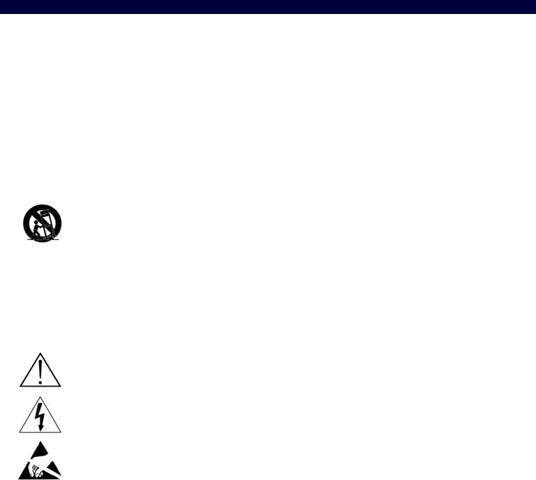
DXLink Multi-Format TX (DX-TX) Front View
Digital Video and Audio LEDs |
Analog Video LEDs |
IR LEDs |
NetLinx LEDs |
USB LED |
Power LED |
Program port 232 (serial) LEDs CEC LED |
ID Pushbutton |
FIG. 1 DX-TX front view
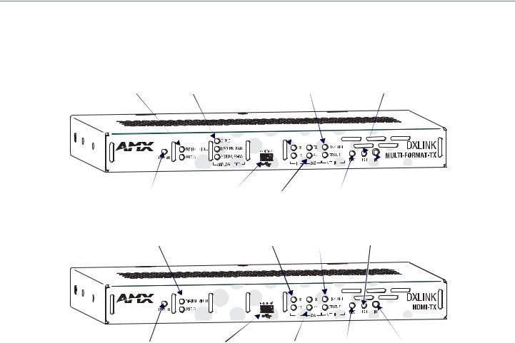
DXLink HDMI TX (AVB-TX-HDMI-DXLINK) Front View (product discontinued)
Digital Video and Audio LEDs |
IR LEDs |
NetLinx LEDs |
USB LED |
Power LED |
Program port |
232 (serial) LEDs CEC LED |
ID Pushbutton |
FIG. 2 HDMI TX front view
Components located on front of DX-TX and HDMI TX (left to right):
Power LED – Indicates when the DX-TX or HDMI TX is powered on
Digital Video and Audio LEDs – Indicate the presence of digital video and digital audio signals, including an embedded audio signal on the HDMI path
Analog Video LEDs (DX-TX only) – Indicate the type of analog video present through the DX-TX: composite or Y/C; Y/Pb/Pr or RGB; RGBHV or RGBS
Program port – This port (USB mini-B connector) supports DGX Configuration Software for programming a customer VGA EDID
IR LEDs – TX and RX LEDs indicate active IR communication
232 LEDs (RS-232 serial) – TX and RX LEDs indicate active serial communication
NetLinx LEDs – Link/Act LED indicates network communication activity. The Status LED indicates unit status. CEC LED – CEC is not currently supported
USB LED – When illuminated, the LED indicates that the USB port is connected and enabled
ID Pushbutton – Places the DX-TX or HDMI TX in ID Mode for setting the NetLinx ID (device only) and provides additional functionality, such as placing the device in Static IP Mode or DHCP Mode
Hardware Reference Manual – DXLink™ Twisted Pair Transmitters/Receiver |
10 |
|
|
|
|
Product Overview and Specifications |
DX-TX and HDMI TX LEDs |
|
|
|
|
|
DX-TX and HDMI TX Indicator LEDs |
|
|
LED |
Normal Display |
Indicates |
|
|
|
Power |
Green |
Power is applied to the Transmitter Module |
|
|
|
Digital Video |
Green |
A digital video signal is present through the Transmitter Module |
|
|
|
Audio |
Green |
Embedded audio signal is present through the Transmitter Module |
|
|
|
Analog Video |
One of the 3 LEDs |
The type of analog video present through the DX-TX: |
(DX-TX only) |
will be Green |
• C (composite) or Y/C (two component) |
|
|
• Y/PB/PR or RGB (three component) |
|
|
• RGBHV (five component) or RGBS (four component) |
|
|
|
IR TX |
Red |
IR TX active communication |
|
|
|
IR RX |
Yellow |
IR RX active communication |
|
|
|
232 (Serial) TX |
Red |
Serial TX active communication |
|
|
|
232 (Serial) RX |
Yellow |
Serial RX active communication |
|
|
|
NetLinx Link/Act |
Green |
Active LAN connection to an AMX Network (Blinking = #3 Toggle OFF) |
|
|
|
NetLinx Status |
Green |
LAN connection is active |
|
|
|
NOTE: For detailed behavior of the NetLinx Link/Act and Status LEDs on the module’s front, see page 50. For detailed behavior of the RJ-45 connector LEDs on the module’s rear, see page 40.
DXLink Multi-Format Wallplate TX (DX-TX-WP) Front View
Left edge |
Reset button |
Program port |
ID Pushbutton |
HDMI Input
Digital Video LED
HD-15 Input
 Analog Video LEDs

 Audio LED
Stereo Audio Input
USB Host
 Power LED
Bottom edge
NetLinx LEDs |
DXLink LEDs |
FIG. 3 Multi-Format Wallplate TX front view, plus left edge and bottom edge views
Components located on front of Wallplate TX:
HDMI In – HDMI connector (with locking center screw) for digital video and embedded digital audio (supports a DVI-D signal with use of DVI-to-HDMI cable adapter). When more than one audio signal is present, HDMI embedded audio takes precedence over analog audio.
Digital Video LED –
Video In – An HD-15 connector for analog video: C (composite), Y/C, Y/Pb/Pr, RGB, RGBHV, or RGBS. Pinouts for analog video are on page 104
Analog Video LEDs – Illuminates when the Wallplate TX is configured to pass analog video: composite or Y/C; Y/Pb/Pr or RGB; RGBHV or RGBS
Audio In Stereo – Audio connector is a 3.5 mm stereo jack. An analog audio signal is only available when HDMI embedded digital audio is not present (or configured for analog audio).
Audio LED –
USB Host port – Mini-B USB connector (supports USB host) for receiving keyboard / mouse commands from a specific RX. (For USB port information, see page 18.)
Power LED – Indicates when the Wallplate TX is powered on
Hardware Reference Manual – DXLink™ Twisted Pair Transmitters/Receiver |
11 |
|
|
Product Overview and Specifications
Components located on left and bottom edges of Wallplate TX:
Reset button (left) – Resets the Wallplate TX’s CPU (acts like a power cycle soft reboot)
Program port (left) – This port (USB mini-B connector) supports DGX Configuration Software for programming a customer VGA EDID
ID Pushbutton (left) – Places the Wallplate TX in ID Mode for setting the NetLinx ID (device only) and provides additional functionality, such as placing the device in Static IP Mode or DHCP Mode
NetLinx LEDs (bottom) – Left green LED (L = Link/Act) indicates network communication activity; right green LED (S = Status) indicates unit status
DXLink LEDs (bottom) – Left yellow LED indicates HDCP status; right green LED indicates that a valid DXLink connection has been established
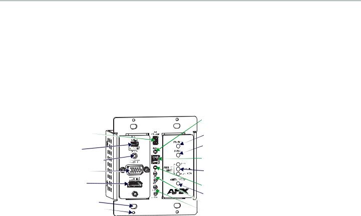
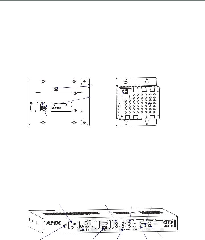
DXLink Decor Wallplate TX (DX-TX-DWP) Front View
|
Reset button |
Program port |
Power LED |
|
|
USB Host |
Audio LED |
|
|
Stereo Audio Input |
DIP switch |
|
|
HD-15 Input |
Analog Video LEDs |
HDMI Input |
ID Pushbutton |
|
Digital Video LED |
Back box screw hole |
DXLink LEDs |
Cover plate screw hole |
NetLinx LEDs |
|
FIG. 4 Decor Wallplate TX front view (before customer provided standard decor style front cover plate is attached)
IMPORTANT: Be sure to measure the back box and any other components used to mount the Decor Wallplate TX prior to installation/ construction to ensure the unit fits (e.g., some mud rings do not work unless their corners are modified).
Components located on left and right front sections of Decor Wallplate TX:
USB Host port – Mini-AB USB connector (supports USB host) for receiving keyboard / mouse commands from a specific RX. (For USB port information, see page 18.)
Audio In Stereo – Audio connector is a 3.5 mm stereo jack. An analog audio signal is only available when HDMI embedded digital audio is not present (or configured for analog audio).
Video In – An HD-15 connector for analog video: C (composite), Y/C, Y/Pb/Pr, RGB, RGBHV, or RGBS. Pinouts for analog video are on page 104
HDMI In – HDMI connector (with locking center screw) for digital video and embedded digital audio (supports a DVI-D signal with use of DVI-to-HDMI cable adapter). When more than one audio signal is present, HDMI embedded audio takes precedence over analog audio.
Power LED – Indicates when the Decor Wallplate TX is powered on
Audio LED – Indicates the unit is configured to pass analog audio (coupled with digital or analog video path)
Analog Video LEDs – Illuminates when the Decor Wallplate TX is configured to pass analog video: composite or Y/C; Y/Pb/Pr or RGB; RGBHV or RGBS
Digital Video LED – Illuminates when the Decor Wallplate TX is configured to pass HDMI with embedded audio (default)
The Decor Wallplate TX has a number of front panel components, some can been seen when a standard decor style front cover plate is attached and some are hidden by the plate (FIG. 4 shows all of them). The cover plate is customer provided to allow matching the individual decor of an environment or matching other standard decor covers in a room/area.
Components located on center front section of Decor Wallplate TX:
USB Program port – This port (USB mini-B connector) supports DGX Configuration Software for programming a customer VGA EDID
Reset button – Resets Decor Wallplate TX’s CPU (acts like power cycle soft reboot)
Dip switch – A four-toggle DIP switch is used for enabling/disabling special functionality (see page 34)
ID Pushbutton – Places the Decor Wallplate TX in ID Mode for setting the NetLinx ID (device only) and provides additional functionality, such as placing the device in Static IP Mode or DHCP Mode
DXLink LEDs – HDCP LED indicates HDCP status; DXLink LED indicates that a valid DXLink connection has been established NetLinx LEDs – Status LED indicates unit status; Link/Act LED indicates network communication activity
Hardware Reference Manual – DXLink™ Twisted Pair Transmitters/Receiver |
12 |
|
|
Product Overview and Specifications
Wallplate TX and Decor Wallplate TX Front LEDs |
||
|
|
|
Wallplate TX and Decor Wallplate TX Indicator LEDs |
||
LEDs |
Normal Display |
Indicates |
|
|
|
Digital Video (default) |
Green |
The Wallplate TX and Decor Wallplate TX have been configured* to pass HDMI (for |
|
|
SEND_COMMAND information, see page 68) |
|
|
|
Analog Video |
One of the 3 LEDs |
The Wallplate TX and Decor Wallplate TX have been configured* to pass one of the following |
|
will be Green |
types of analog video (for SEND_COMMAND information, see page 68): |
|
|
• C (composite) or Y/C (two component) |
|
|
• Y/PB/PR or RGB (three component) |
|
|
• RGBHV (five component) or RGBS (four component) |
|
|
|
Audio |
Green |
The Wallplate TX and Decor Wallplate TX have been configured* to pass analog audio as the |
|
|
audio source being embedded on the DXLink output connection (coupled with either the |
|
|
analog or digital video input path); for SEND_COMMAND information, see page 72 |
|
|
|
Power |
Green |
Power (from switcher) is applied to the unit |
|
|
|
LEDs (bottom edge of |
Wallplate TX) |
|
NetLinx - L (Link) |
Green |
Active LAN connection to an AMX Network (Blinking = #3 Toggle OFF) |
|
|
|
NetLinx - S (Status) |
Green |
• Speed status is 100 Mbps |
|
Off |
• Speed status is 10 Mbps |
|
|
|
DXLink Yellow |
Yellow |
• Authenticated HDCP (handshaking has occurred successfully) |
|
Flashing |
• Video is active; no HDCP |
|
Off |
• No Video |
|
|
|
DXLink Green |
Green |
DXLink connection is established |
|
|
|
LEDs (under customer |
provided front cover |
plate on Decor Wallplate TX) |
HDCP (DXLink) |
Yellow |
• Authenticated HDCP (handshaking has occurred successfully) |
|
Flashing |
• Video is active; no HDCP |
|
Off |
• No Video |
|
|
|
DXLink |
Green |
DXLink connection is established |
|
|
|
Status (NetLinx) |
Green |
• Speed status is 100 Mbps |
|
Off |
• Speed status is 10 Mbps |
|
|
|
Link/Act (NetLinx) |
Green |
Active LAN connection to an AMX Network (Blinking = #3 Toggle OFF) |
|
|
|
* The LEDs for Digital Video, Analog Video, and Audio each indicate the configured state of the connectors, not necessarily the presence of signals through the Wallplate TX and Decor Wallplate TX.
NOTE: Detailed behavior for the NetLinx-L and NetLinx-S LEDs on the Wallplate TX or Link/Act and Status LEDs on the Decor Wallplate TX are on page 50, and basic information for the LEDs on the RJ-45 connector on the rear of the Wallplate TX and Decor Wallplate TX is on page 40.
TIP: If the Wallplate TX is installed in a location where it is difficult to check the LEDs on the bottom edge, slide a white piece of paper or a small mirror under the edge to view LED status.
DX-TX Rear View
HDMI In connector Stereo Audio In jack |
Digital Audio In jack USB port |
Power jack |
Ground screw
|
ICS LAN 10/100 connector |
IR ports |
Video In connector |
RS-232 port |
DXLink output connector |
FIG. 5 DX-TX rear view |
|
|
Hardware Reference Manual – DXLink™ Twisted Pair Transmitters/Receiver |
13 |
|
|
Product Overview and Specifications
HDMI TX Rear View (product discontinued)
HDMI In connector |
Stereo Audio In jack Digital Audio In jack |
USB port |
Power jack |
|
|
|
Ground screw |
ICS LAN 10/100 connector |
IR ports |
RS-232 port |
DXLink output connector |
FIG. 6 HDMI TX rear view
NOTE: The DX-TX and HDMI TX each have a DIP switch on the bottom (see page 17).
The following components are located on the rear of DX-TX and HDMI TX Modules (from left to right):
Video In Connector (DX-TX only) – The Video In connector on the DX-TX is an HD-15 connector for analog video (composite, Y/C, Y/Pb/Pr, RGB, RGBHV, or RGBS). Pinouts for analog video are on page 104.
NOTE: When an analog video source cable is plugged into the DX-TX, the Video LEDs on the front and on the Receiver turn green to show that video is present through the system. In addition, one of the Analog Video LEDs on the front of the DX-TX and the DXRX turns green to show the type of video that is present through the system.
HDMI In Connector – The HDMI In connector is for digital video and embedded digital audio. When more than one audio signal is present and the default “auto” mode is enabled, HDMI embedded audio takes precedence over S/PDIF and analog audio.
When a NetLinx Central Controller is connected, an audio format SEND_COMMAND is available (the Transmitter must be set for network connectivity via #3 Toggle) to select the desired audio source (see page 72).
The HDMI connector has a center screw for locking capability. The HDMI connector also supports a DVI-D signal with the use of a DVI-to-HDMI cable adapter.
NOTE: When a digital video source cable is plugged into the HDMI connector, the Video LEDs on the front of the DX-TX or HDMI TX and Receiver turn green to show that video is present through the system.
Stereo Audio In Jack – The Stereo Audio In jack is a 3.5 mm stereo jack. By default, the stereo audio jack will be third in priority behind the embedded audio on the HDMI input and digital audio on the RCA connector.
When a NetLinx Central Controller is connected, an audio format SEND_COMMAND is available (the Transmitter must be set for network connectivity via #3 Toggle) to select the desired audio source (see page 72).
Digital Audio In Jack– The Digital Audio In jack is an RCA jack for an S/PDIF audio signal. When more than one audio signal is present and the default “auto” mode is enabled, HDMI embedded audio takes precedence over S/PDIF, which takes precedence over analog audio.
When a NetLinx Central Controller is connected, an audio format SEND_COMMAND is available (the Transmitter must be set for network connectivity via #3 Toggle) to select the desired audio source (see page 72).
ICS LAN 10/100 Connector – The ICS LAN 10/100 (RJ-45) connector provides for Ethernet 10/100 connectivity (e.g., receiving SEND_COMMANDs and downloading firmware update files). For pinout and LED information, see page 39.
RS-232 (Serial) Port – The RS-232 port (serial data interface) is a 3-position screw terminal block which accepts data from the source device and transfers it via the twisted pair cable to the DX-RX, which in turn transfers the data to the destination device. The transfer of data can also be made from the destination to the source. In addition to being directly connected to a device, this port can be connected as an independent native NetLinx control port from a networked NetLinx Central Controller.
IR RX Port – The IR RX port is used for IR control (see page 19). This port is a 3.5 mm stereo jack. In addition to being directly connected to a device, this port can be connected as an independent native NetLinx control port from a networked NetLinx Central Controller.
IR TX Port– The IR TX port is used for IR control (see page 19). This port is a 2-way mini-Phoenix connector. In addition to being directly connected to a device, this port can be connected as an independent native NetLinx control port from a networked NetLinx Central Controller.
USB Port – The USB-B port on the rear of the DX-TX and HDMI TX is connected to a PC and supports a USB device. This is the Host port that is used in conjunction with the USB-A port on the rear of the DX-RX for sending keyboard / mouse commands to a connected PC at the Transmitter. (For USB port information, see page 18.)
DXLink Output Connector – The DXLink (RJ-45) connectors transport digital video, embedded audio, Ethernet, and bidirectional control over twisted pair cable to DXLink devices or boards (or an DX-RX), including digitally transcoded analog video signals. The DXLink path supports HDCP. The DXLink line also supports power from an Enova DGX Switcher and from some Enova DVX Solutions to power the module. For pinout and LED information, see page 39.
Ground Screw – The ground screw is used for creating a technical ground for the ungrounded sources/destinations with respect to the DXLink Transmitters/Receivers and switcher (see page 37).
Hardware Reference Manual – DXLink™ Twisted Pair Transmitters/Receiver |
14 |
|
|
Product Overview and Specifications
Power Jack – The power receptacle is a 2.1 mm DC jack for connecting power. Power can come from a locally connected DC supply of 12 V. The automatically adjusting universal 110/220 IEC power supply is provided. The power supply is ENERGY STAR® qualified to ensure maximum efficiency and savings.
IMPORTANT: If desktop power is used to power the Transmitter, only the provided desktop power supply should be used and it must not be altered in any way. Remote power can also be provided via a switcher, PDXL-2 (FG1090-170), or PS-POE-AT-TC (FG423-84).
NOTE: Transmitter Modules can also be powered via the DXLink connector when attached to a DXLink Input Board in an Enova DGX Switcher. We recommend calculating the power budget for the switcher to maintain the redundancy of its power supplies (see page 31).
Wallplate TX and Decor Wallplate TX Rear View
Located on the rear of the Wallplate TX are a DXLink (RJ-45) connector and a DIP switch.
The Decor Wallplate TX also has its DXLink connector on the rear, but its DIP switch is on the front (see page 17). The front can be covered with a customer provided standard decor style front cover plate.
DIP switch
DXLink 

 connector


 Ground screw
FIG. 7 Wallplate TX rear view (mounting bracket removed) and Decor Wallplate TX rear view
DXLink Output Connector – The DXLink (RJ-45) connectors transport digital video, embedded audio, bidirectional control, and Ethernet (SEND_COMMANDs only) over twisted pair cable to DXLink devices or boards, including digitally transcoded analog video signals. The DXLink path supports HDCP. In addition, the Wallplate TX and Decor Wallplate TX receive power over the DXLink line from an Enova DGX Switcher, some Enova DVX Solutions, or PDXL-2 (FG1090-170) or PS-POE-AT-TC (FG423-84). For pinout and LED information, see page 40.
DIP Switch – The DIP switch is on the rear of the Wallplate TX. It is on the front of the Decor Wallplate TX and can be covered with a customer provided standard decor style front cover plate. For information on the DIP switch, see page 17.
Ground Screw – The ground screw is used for creating a technical ground for the ungrounded sources/destinations with respect to the DXLink Transmitters/Receivers and switcher (see page 37).
Receiver
NOTE: If a DVI-D signal is used (via a DVI-to-HDMI cable adapter), the advanced audio support from HDMI will not be available.
DXLink HDMI Receiver (DX-RX) Front View
Video and Audio LEDs |
IR LEDs |
NetLinx LEDs |
USB LED |
Power |
Scaling LEDs |
Program port |
232 (serial) LEDs CEC LED |
ID Pushbutton |
FIG. 8 DX-RX front view
NOTE: The DX-RX has a DIP switch on the bottom; for details, see page 17.
Hardware Reference Manual – DXLink™ Twisted Pair Transmitters/Receiver |
15 |
|
|
Product Overview and Specifications
The following components are located on the front of the DX-RX (left to right):
Power LED – Indicates when the DX-RX is powered on.
Video and Audio LEDs – Indicate the presence of video and embedded audio signals through the DX-RX.
Scaling button and LEDs – Use the Scaling button to select one of the 3 scaling options: Bypass, Auto (default), or Manual. For information on using the Scaling button and options for persisting the Scaling Mode, see page 49.
Program port – This port is a USB mini-B connector.
IR LEDs – TX and RX LEDs indicate active IR communication.
232 (RS-232) LEDs – TX and RX LEDs indicate active serial communication.
NetLinx LEDs – Link/Act LED indicates network communication activity. The Status LED indicates unit status. CEC LED – CEC is not currently supported.
USB LED – When illuminated, the LED indicates that the USB port connection has been established (for details, see page 19).
ID Pushbutton – Places the DX-RX in ID Mode for setting the NetLinx ID (device only) and provides additional functionality, such as placing the device in Static IP Mode or DHCP Mode.
Receiver Module LEDs
HDMI RX Indicator LEDs
LED |
Normal Display |
Indicates |
|
|
|
Power |
Green |
Power is applied to the Receiver |
|
|
|
Video |
Green |
A video signal is present through the Receiver |
|
|
|
Audio |
Green |
An embedded audio signal is present through the Receiver |
|
|
|
Scaling: |
|
The Receiver is in one of the three modes for scaling |
– Bypass |
One LED is green |
• At initial power up, the Receiver defaults to the Auto scaling option* |
– Auto |
The other two are off |
• Pressing the Scaling button cycles the module through the options: Bypass, Auto, and |
– Manual |
|
Manual |
|
|
• If Bypass is solid and Auto is flashing, then the RX is trying to read EDID from the sink |
|
|
|
IR TX |
Red |
IR TX active communication |
|
|
|
IR RX |
Yellow |
IR RX active communication |
|
|
|
Serial TX |
Red |
Serial TX active communication |
|
|
|
Serial RX |
Yellow |
Serial RX active communication |
|
|
|
NetLinx Link/Act |
Green |
Active LAN connection to an AMX Network (Blinking = #3 Toggle OFF) |
|
|
|
* When the output cable is disconnected from the DX-RX or if no EDID can be found on the destination device, the last used Scaling Mode LED will be ON. In either case, the DX-RX will continue to hold its output resolution to the last known preferred resolution until a power cycle or reconnection of a sink with a valid EDID. On power up without a valid EDID, the default preferred output resolution presented will be 1280x1024,60Hz until a different EDID is detected.
NOTE: For detailed behavior of the NetLinx Link/Act and Status LEDs on the module’s front, see page 50. For detailed behavior of the RJ-45 connectors’ LEDs on the module’s rear, see page 40.
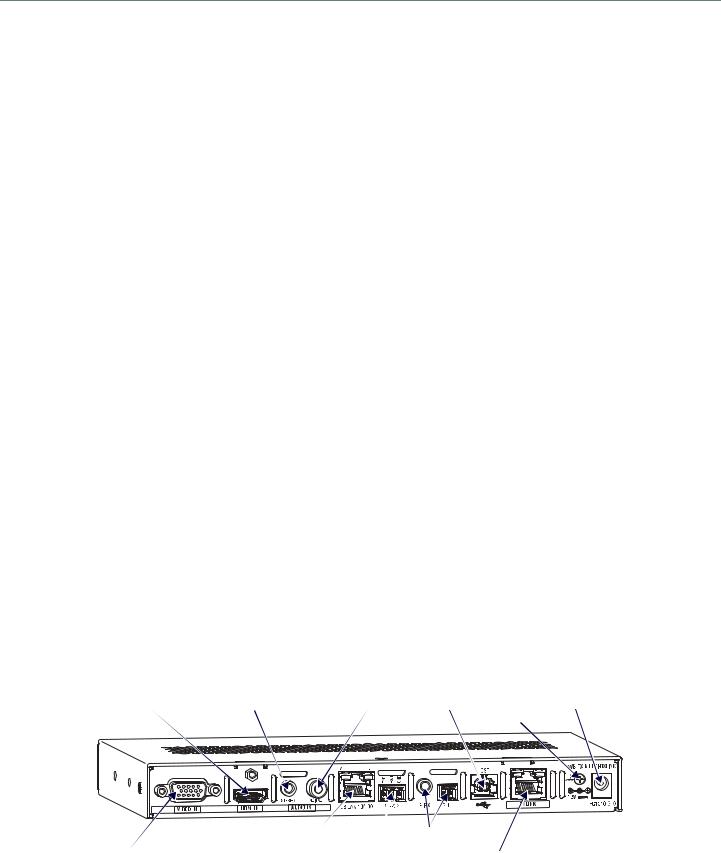
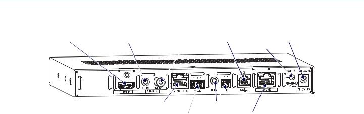
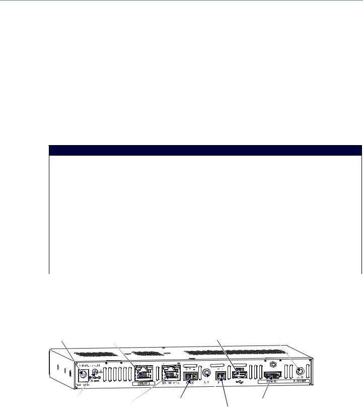
Receiver Rear View
Power jack |
DXLink input connector |
USB port |
Stereo Audio Out connector |
Ground screw |
RS-232 port |
HDMI Out connector |
ICS LAN 10/100 |
|
IR ports |
FIG. 9 DX-RX rear view
The following components are located on the rear of the DX-RX (left to right):
Power Jack – The power receptacle is a 2.1 mm DC jack for connecting power. Power can come from a locally connected DC supply of 12 V. An automatically adjusting universal 110/220 IEC power supply is provided. The power supply is ENERGY STAR® qualified to ensure maximum efficiency and savings.
IMPORTANT: If desktop power is used to power the Receiver, only the provided desktop power supply should be used and it must not be altered in any way. Remote power can also be provided via a switcher, PDXL-2 (FG1090-170), or PS-POE-AT-TC (FG423-84).
Hardware Reference Manual – DXLink™ Twisted Pair Transmitters/Receiver |
16 |
|
|
Product Overview and Specifications
NOTE: The DX-RX can also be powered through the DXLink connector when it is attached to a DXLink Output Board in an Enova DGX Switcher. We recommend calculating the power budget for the switcher to maintain the redundancy of its power supplies (see page 31).
Ground Screw – The ground screw is for creating a technical ground for the ungrounded sources/destinations with respect to the DXLink Transmitters/Receivers and switcher (see page 37).
DXLink Input Connector – The DXLink (RJ-45) connectors transport digital video, embedded audio, Ethernet, and bidirectional control over twisted pair cable to DXLink devices or boards, including digitally transcoded analog video signals. The DXLink path supports HDCP and also supports power over the same path from an Enova DGX Switcher and from some Enova DVX Solutions to power the module. For pinout and LED information, see page 39.
ICS LAN 10/100 Connector – The ICS LAN 10/100 (RJ-45) connector is for Ethernet 10/100 connectivity (e.g., receiving SEND_COMMAND commands and downloading firmware update files). For pinout and LED information, see page 39.
RS-232 Port – The RS-232 (serial data interface) port is a 3-position screw block which accepts data from the source device and transfers it via the twisted pair cable to the DX-RX, which in turn transfers the data to the destination device or the transfer of data can also be made from the destination to the source. In addition to being directly connected to a device, this port can be connected as an independent native NetLinx control port from a networked NetLinx Central Controller.
IR RX Port – The IR RX port is used for IR control (see page 19). This port is a 3.5 mm stereo jack. In addition to being directly connected to a device, this port can be connected as an independent native NetLinx control port from a networked NetLinx Central Controller.
IR TX Port – The IR TX port is used for IR control (see page 19). This port is a 2-way mini-Phoenix connector. In addition to being directly connected to a device, this port can be connected as an independent native NetLinx control port from a networked NetLinx Central Controller.
USB Port – The USB-A port on the RX supports keyboard/mouse. This port is used in conjunction with the USB-B Host port on the HDMI TX which supports a USB device and connects to the PC. (For USB port information, see page 18.)
HDMI Out Connector – The HDMI Out connector is for digital video and embedded audio. The HDMI connector has a center screw for locking capability. The HDMI connector also supports a DVI-D signal (a DVI-to-HDMI cable adapter is required).
Stereo Audio Out Connector – The Stereo Audio Out connector is a 3.5 mm stereo jack. This connector has an analog audio signal available for output whether the embedded audio over the DXLink cable originated as 2 channel digital or analog stereo. If encoded digital audio (e.g., Dolby or DTS) or multi-channel audio paths (>2 CH L-PCM) are embedded on the HDMI path, then this local analog port out will not be available.
Common Features/Functionality
This section covers the DIP switches, the USB port, HDCP compliance, and IR functionality.
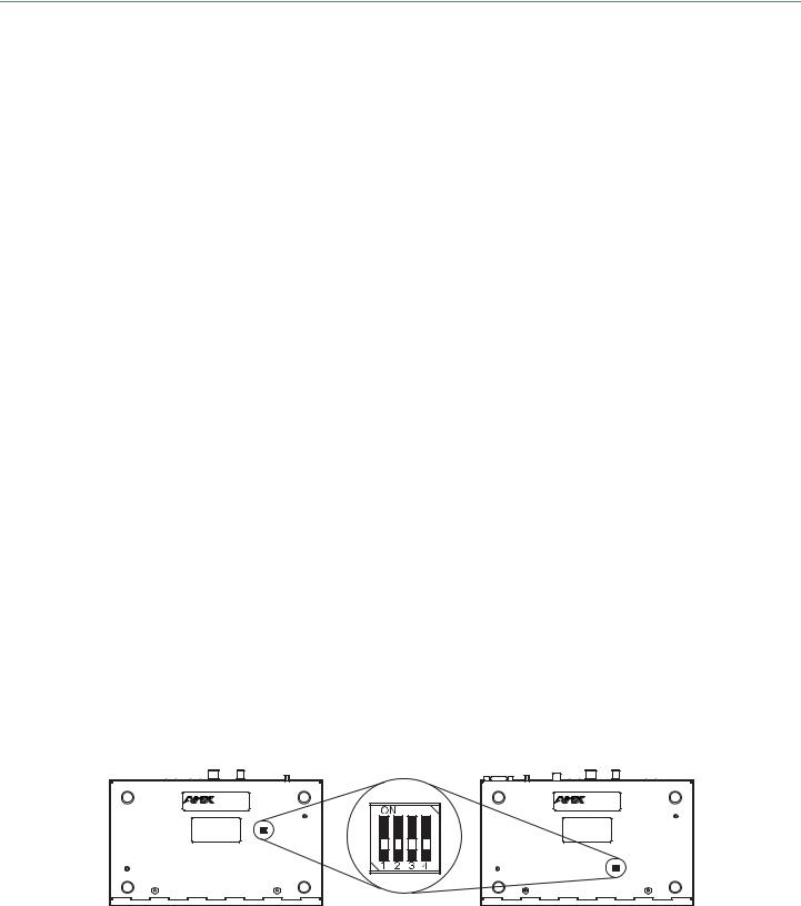
DIP Switches
TIP: For easiest access to the DIP switch toggles, we recommend setting them before installation.
A four-toggle DIP switch is on the bottom of the DXLink Modules, on the rear of the Wallplate TX, and on the front of the Decor Wallplate TX (the front can be covered with a customer provided standard decor style front cover plate).
#1 Toggle is used for enabling/disabling the physical ICS LAN 10/100 port (see page 34).
#2 Toggle is used for setting the DXLink Modules to either automatically or manually determine the DXLink Mode (see page 35).
#3 Toggle is used for enabling/disabling network connectivity of the DXLink Transmitter or Receiver to a connected NetLinx Central Controller (used for IR ports, serial ports, and commands to the DXLink unit); see page 35.
#4 Toggle is not functional.
DIP switch
Receiver |
FIG. 10 DIP switch location on DXLink Modules |
Transmitter |
NOTE: The mounting bracket on the Wallplate TX must be removed (unscrew the four screws from the bracket and set it aside) before the DIP switch toggles can be set.
Hardware Reference Manual – DXLink™ Twisted Pair Transmitters/Receiver |
17 |
|
|

Product Overview and Specifications
Wallplate TX |
Decor Wallplate TX |
|
DIP switch |
FIG. 11 DIP switch on Wallplate TX (remove mounting bracket) and on Decor Wallplate TX
For complete information on setting DIP switches (including settings for common scenarios), see the section starting on page 34.
USB Port (Rear)
DX-TX
USB port - host |
USB port - keyboard/mouse |
DX-RX |
|
FIG. 12 TX USB port = host (top); RX USB port = keyboard/mouse (bottom)
DX-TX and HDMI TX
The USB-B port on the rear of the DX-TX and HDMI TX can be connected to a PC to support a USB device. This port is considered the Host port, which is used in conjunction with the USB-A port on the rear of the DX-RX. As the Host port, it is connected to a PC and passes through information via the DXLink connection to the DX-RX. A USB (mini-B) Host port is also available on the Wallplate TX and a USB (mini-AB) Host port is available on the Decor Wallplate TX.
DX-RX
The USB-A port on the rear of the DX-RX supports passthrough information from the USB Host port on the Transmitter to an HID (Human Interface Device), which is most commonly a keyboard or mouse.
HID Devices and Windows 8
Windows 8 will not wake up from a DXLink connected keyboard or mouse unless the properties for the HID device are set to allow the device to wake the computer. (Note that even a hot plug of the USB cable will not restore connectivity.)
To set Windows 8 to work with DXLink modules and HID devices:
1.On the PC, go to Start > Control Panel > Device Manager and expand “Keyboards.”
2.Right-click the HID Keyboard Device and select Properties. The HID Keyboard Device Properties dialog box opens.
HID Keyboard Device
Select Properties
Hardware Reference Manual – DXLink™ Twisted Pair Transmitters/Receiver |
18 |
|
|

HID Devices
USB LED
Product Overview and Specifications
3.Select the Power Management tab and click “Allow this device to wake the computer.”  Select this option
4.Click OK.
5.Repeat steps for HID mouse (in the Device Manager dialog box, expand “Mice”).
HID Devices
A list is available of HID devices which have been tested and found to be working well with the latest firmware (see “DXLink - HID supported Devices” on the DXLink Receiver’s product page at www.amx.com).
USB LED
The USB LED on the front of a Transmitter or Receiver Module monitors the USB port on the rear of the unit. The USB LED illuminates (yellow) when a USB device is detected (the port default is “enabled”).
To disable the port on the Transmitter, either disconnect the cable or send the following SEND_COMMAND: USB_HID_SERVICEDISABLE. The enable/disable command persists through power cycling. To enable the port, send: USB_HID_SERVICE-ENABLE. The USB ports support a limited number of SEND_COMMANDs, see page 77.
HDCP Compliance
If the connected downstream sink is not HDCP compliant, then the HDMI output on the Receiver will not send the signal. This does not affect additional displays the source may be routed to, i.e., HDCP compliant displays will still show content from the source device even when the source device is also routed to non-compliant displays. Non-compliant devices can be easily identified because they display a dark red image or an orange image to indicate the authentication process failed.
IR Control on DX-TX, HDMI TX, and DX-RX (Optional)
The following two items are required for IR control. In addition, a compatible remote control unit can be used with the system. (The two items listed are not included with the modules.)
IR03 – External IR Receiver Module (FG-IR03). The IR03 can be connected to the IR RX port on the DX-TX or HDMI TX or to the IR RX port on the DX-RX, allowing IR signals to be received from a compatible IR remote control. The IR03 allows the DX-TX or HDMI TX to be placed behind the display device if desired.
CC-NIRC – NetLinx IR Emitter Cable (FG10-000-11). The CC-NIRC can be connected to the IR TX port on the Transmitter or to the IR TX port on the DX-RX. This allows IR signals to be sent to the source device from the DX-TX or HDMI TX or to the display device from the Receiver.
Hardware Reference Manual – DXLink™ Twisted Pair Transmitters/Receiver |
19 |
|
|

Product Overview and Specifications
Quick Reference Tables for Modes
The modes listed in the following three tables are those supported by DXLink Transmitters and Receivers. The Quick Reference Tables are intended to help users navigate the many modes available for system setup and use. For complete information on any of the modes listed, see the relevant sections or chapter referenced at the end of the Descriptions.
Quick Reference Table – Modes for Handling System Architecture
Mode |
Description |
|
|
DXLink Modes |
DXLink Modes refer to the type of physical components and how they are connected to make up the system. When |
|
Transmitters and Receivers are cabled into a system and powered on, they automatically detect the DXLink Mode they |
|
are being used in. |
|
Endpoint Mode: |
•When the system is setup to use Transmitters and/or Receivers with an Enova DGX Digital Media Switcher or an applicable Enova DVX Solution, the system is in Endpoint Mode (see example on page 28).
Or
•When a TX is directly connected to an RX but, in addition, the TX and/or RX is connected to a NetLinx Central Controller via a LAN or directly connected to the Controller, the system is in Endpoint Mode (see example on page 30).
Extender Mode:
•When a TX is directly connected to an RX, the system is in Extender Mode (see example on page 31).
For further information, reference #2 Toggle DIP switch settings for DXLink Mode (see page 35) and DXLink System SEND_COMMANDs (see page 79).
Quick Reference Table – Modes for Handling Addressing/Networking
Mode |
Description |
|
|
IP Addressing |
IP Addressing Modes refer to network connection settings. By default, all network connection settings are turned OFF. |
Modes |
Static IP Mode: |
|
• This mode configures the network connection to one stable IP address the device will use continuously. |
|
DHCP Mode: |
|
• This mode configures the network connection to choose a new IP address for each network session. |
|
To enable network capability, see “Network Configuration” on page 52. |
|
|
ID Mode |
ID (Identify) Mode refers to the protocol for enabling a user to establish device addresses. This Mode, accessible |
|
through NetLinx Studio, places the entire system on hold while it waits for an event from a NetLinx device in the |
|
named system (e.g., pressing the ID Pushbutton on the TX or RX). For further information, see “Assign a Device |
|
Address (ID Mode)” on page 57. |
|
|
Ethernet Modes |
Ethernet Modes refer to the LAN configuration settings. |
|
Auto Mode: |
•This mode configures the LAN driver to discover its own settings based on the network it is connected to.
Speed/Duplex Mode:
•This mode configures the LAN driver to calculate its speed as either 10 or 100 and to communicate in either halfor full-duplex.
Ethernet Mode discovery and configuration information is available through Telnet commands. For further information, see “Establishing a Terminal Connection Via Telnet” on page 90.
Master |
Master Connection Modes refer to the modes of communication used for connection to the Master as specified via |
Connection |
the SET CONNECTION Telnet command. |
Modes |
Auto Mode: |
|
This mode utilizes TCP communication. It looks for a matching System Number and attempts to come online with the |
|
first Master it sees with that System Number. |
|
TCP URL Mode: |
|
TCP; the Master is specified via URL. |
|
UDP URL Mode: |
|
UDP; the Master is specified via URL. |
|
NDP Mode (Default): |
|
UDP; utilizes the NDP binding process to assign the DXLink Module (the physical device) to a Master (or Virtual |
|
Master) via NetLinx Studio. Once bound, communications are conducted via UDP. |
|
For further information, see “Master Connection Modes” on page 97. |
Hardware Reference Manual – DXLink™ Twisted Pair Transmitters/Receiver |
20 |
|
|
|
Product Overview and Specifications |
|
|
Quick Reference Table – Modes for Handling Addressing/Networking (continued) |
|
Auto-setup Mode |
In auto-setup mode, endpoints are automatically discovered by and connected to an Enova DGX |
|
100 Series Switcher using a single IP address. For this mode, all of the following requirements must |
|
be met. If not, the endpoint will no longer reside in auto-setup mode and must be either bound to |
|
the integrated Master (see page 52) or reconfigured to meet the requirements. |
|
Endpoint must be connected to a DXLink Input Board in an Enova DGX 100 Series |
|
Switcher (or Enova DGX 8/16/32/64 with upgraded 100 Series CPU) |
|
Endpoint must have IP mode set to DHCP for setup (self-configures to Static IP on |
|
private LAN) |
|
Endpoint must have the master connection type set to NDP |
|
Endpoint must not be bound to a Master via NDP (traditional binding process) |
|
IMPORTANT: If auto-setup is being used, Telnet is the only way to access some of the network |
|
settings. Also note that some network settings will disable auto-setup. |
|
For additional information on the auto-setup feature, see the Hardware Reference Manual – |
|
Enova DGX 100 Series Digital Media Switchers. |
|
|
IR SEND_COMMAND Modes |
IR SEND_COMMAND Modes refer to displaying and setting the IR port active system settings as IR, |
|
Serial, or Data modes. |
|
GET MODE SEND_COMMAND: |
|
• The GET MODE SEND_COMMAND reveals the active system (IR, Serial, or Data) settings. |
|
SET MODE SEND_COMMAND: |
|
• The SET MODE SEND_COMMAND changes the active system settings. |
|
For further information, see “IR SEND_COMMANDs” on page 73. |
|
|
Quick Reference Table – Modes for Handling Video Processing
Mode |
Description |
|
|
Scaling Modes |
Scaling Modes refer to how the system alters or maintains a source device’s resolution as it is passed along to the |
|
destination device. The Scaling Mode can be set on the DX-RX with the Scaling button (see page 49), or with |
|
SEND_COMMANDs (see page 66), or through DGX Configuration Software when scaling is being done via an Enova |
|
DXLink Output Board. |
|
Auto Mode (Default): |
|
• Auto Mode (SmartScale®) allows the destination device to choose the resolution it needs. |
|
Manual Mode: |
|
• Manual Mode allows the user to configure the resolution the video will display through a destination device. |
|
Bypass Mode: |
|
• Bypass Mode allows the video signal to display over the destination device without altering the signal’s resolution. |
|
|
DXLink Transmitters and Receiver Specifications
The specifications in the table below apply to the following Transmitters and Receiver: FG1010-310 – DX-TX
FG1010-300 – DXLink HDMI TX Module (discontinued) FG1010-320-BL – DX-TX-WP, Black* FG1010-320-WH – DX-TX-WP, White* FG1010-325-BL – DX-TX-DWP (US), Black* FG1010-325-WH – DX-TX-DWP (US), White* FG1010-500 – DX-RX
* A limited set of specifications apply, as the Wallplate TX and Decor Wallplate TX have a limited set of features when compared to the DX-TX and HDMI TX.
General Specifications
Parameter |
|
Value |
|
|
|
Approvals |
CE, UL, cUL, FCC Class A, RoHS, WEEE |
|
|
|
|
AC Power (Modules Only) |
• |
100 to 240 VAC single phase, 50 Hz to 60 HZ |
|
• |
0.6 A @ 115 VAC max. |
|
|
|
Hardware Reference Manual – DXLink™ Twisted Pair Transmitters/Receiver |
21 |
|
|

|
|
Product Overview and Specifications |
|
|
|
General Specifications (continued) |
||
Parameter |
|
Value |
|
|
|
DXLink Power |
• DXLink Twisted Pair Transmitters (DX-TX, DX-TX-DWP, and DX-TX-WP): Power can also be |
|
|
|
supplied by a DXLink Power sourcing device such as an Enova DGX 8/16/32/64 Digital Media |
|
|
Switcher or compatible Enova DVX All-In-One Presentation Switcher (DVX-3155HD, 3156HD, |
|
|
or 2155HD), PS-POE-AT-TC High Power PoE Injector (FG423-84) or PDXL-2 Power over DXLink |
|
|
Controller (FG1090-170). AMX does not support the use of any other power supplies or |
|
|
PoE injectors as these may potentially damage the DXLink equipment. To use PS-POE-AT-TC as a |
|
|
power source the DX-TX Transmitter and the DX-TX-DWP and DX-TX-WP Transmitter Wallplates |
|
|
require firmware v1.2.40 or above. |
|
• DXLink Twisted Pair Receiver (DX-RX): |
|
|
|
Power can also be supplied by a DXLink Power sourcing device such as an |
|
|
Enova DGX 8/16/32/64 Digital Media Switcher or compatible Enova DVX |
|
|
All-In-One Presentation Switcher (DVX-2150HD, or 2155HD), PS-POE-AT-TC High Power |
|
|
PoE Injector (FG423-84), PDXL-2 Power over DXLink Controller (FG1090-170), or |
|
|
SDX-510M-DX Solecis 5x1 Multi-Format Digital Switcher (FG1010-315). AMX does not |
|
|
support the use of any other power supplies or PoE injectors as these may potentially |
|
|
damage the DXLink equipment. To use PS-POE-AT-TC as a power source the DX-RX |
|
|
Receiver requires firmware v1.0.80 or above. |
|
• Power Budget for Transmitters and Receiver: |
|
|
|
When installed in conjunction with the Enova DGX Digital Media Switcher, use the Enova |
|
|
DGX Configuration Tool located at www.amx.com/enova to determine the power |
|
|
requirements of the configuration and whether any of the DXLink Transmitters or Receivers |
|
|
should be powered with the local power supplies or the supported Power over DXLink |
|
|
injector. The configuration tool contains instructions on how to determine power |
|
|
requirements. |
|
|
|
Power Consumption, |
• DX-TX 10 W (13.5 V) |
|
Local 12 V Supplied (max.) |
• HDMI TX 9 W |
|
|
• |
DX-RX 18 W |
|
|
|
Power Consumption, |
• |
DX-TX 10 W |
Enova DXLink Power Supplied (max.) |
• HDMI TX 9 W |
|
|
• Wallplate TX 7 W |
|
|
• Decor Wallplate TX 7 W |
|
|
• |
DX-RX 15 W |
|
|
|
Thermal Dissipation, |
• DX-TX 34 BTU/hr. (13.5 V) |
|
Local 12 V Supplied (max.) |
• HDMI TX 31 BTU/hr. |
|
|
• |
DX-RX 61 BTU/hr. |
|
|
|
Thermal Dissipation, |
• |
DX-TX 34 BTU/hr. |
Enova DXLink Power Supplied (max.) |
• HDMI TX 31 BTU/hr. |
|
|
• Wallplate TX 24 BTU/hr. |
|
|
• Decor Wallplate TX 24 BTU/hr. |
|
|
• |
DX-RX 51 BTU/hr. |
|
|
|
Power Connector (Modules Only) |
2.1 mm DC power jack |
|
|
|
|
Operational Temperature |
32° F to 104° F (0° C to 40° C) |
|
|
|
|
Storage Temperature |
-22° F to 158° F (-30° C to 70° C) |
|
|
|
|
Operational Humidity |
5 to 85% RH (non-condensing) |
|
|
|
|
Storage Humidity |
0 to 90% RH (non-condensing) |
|
|
|
|
Module - Dimensions |
|
|
Depth |
5.15 in. (13.08 cm) |
|
Width |
8.71 in. (22.12 cm) |
|
Height |
1.00 in. (2.54 cm) |
|
|
|
|
Module - Weight |
Approximately 1.1 lb. (0.50 kg) |
|
|
|
|
Module - Shipping Weight |
Approximately 2.2 lb. (1.00 kg) |
|
|
|
|
Modules - Mounting Options |
Compatible with all V Style versatile mounting options including rack, surface, or pole (for V Style |
|
|
Mounting kits, see www.amx.com) |
|
|
|
|
Wallplate TX - Dimensions |
|
|
Depth |
1.31 in. (3.33 cm) |
|
Width |
5.98 in. (15.20 cm) |
|
Height |
4.69 in. (11.90 cm) |
|
|
|
|
Wallplate TX - Weight |
Approximately 1.4 lb. (0.64 kg) |
|
|
|
|
Wallplate TX - Shipping Weight |
Approximately 2.0 lb. (0.91 kg) |
|
|
|
|
Wallplate TX - Mounting Options |
Wallplate TX mounts onto standard double-gang US, UK, or EU back boxes |
|
|
|
|
Hardware Reference Manual – DXLink™ Twisted Pair Transmitters/Receiver |
22 |
|
|

Twisted pair Cable
Specs
Product Overview and Specifications
General Specifications (continued)
Decor Wallplate TX -Dimensions |
|
|
Depth |
2.25 in. (5.72 cm) |
|
Width |
3.48 in. (8.84 cm) |
|
Height |
4.06 in. (10.31 cm) |
|
|
|
|
Decor Wallplate TX - Weight |
Approximately 0.75 lb. (0.34 kg) |
|
|
|
|
Decor Wallplate TX - Shipping Weight |
Approximately 1.35 lb. (0.61 kg) |
|
|
|
|
Decor Wallplate TX - Mounting |
Decor Wallplate TX mounts in standard double-gang US back box |
|
|
|
|
MTBF |
381,000 hours |
|
|
|
|
Transport Layer Throughput |
10.2 Gbps |
|
|
|
|
Twisted Pair Cable Type |
Shielded Cat6, Cat6A, Cat7* |
|
|
|
|
Twisted Pair Cable Length |
Up to 328 ft. (100 m)* |
|
|
IMPORTANT: DXLink twisted pair cable runs for DXLink equipment shall only be run within a |
|
|
common building. “Common building” is defined as: Where the walls of the structure(s) are |
|
|
physically connected and the structure(s) share a single ground reference. |
|
|
* For more details and helpful cabling information, reference the white paper titled “Cabling for |
|
|
Success with DXLink” available at www.amx.com or contact your AMX representative. |
|
|
|
|
Modules - Airflow |
Convection (openings on top of case) |
|
|
|
|
Transmitters and Receiver |
All DXLink Transmitters can connect directly to the DXLink DX-RX. The Wallplate TX and Decor |
|
Inter-compatibility |
Wallplate TX require either PDXL-2 (FG1090-170) or PS-POE-AT-TC (FG423-84) to do so. |
|
|
|
|
Other AMX Equipment |
|
|
|
|
|
AMX Products Compatible with |
• |
DX-RX |
All DXLink Transmitters |
• Enova DGX Digital Media Switchers |
|
|
• |
Enova DVX-3156HD |
|
• |
Enova DVX-3155HD |
|
• |
Enova DVX-2155HD |
|
|
|
AMX Products Compatible with |
• |
DX-TX |
DXLink Receiver |
• |
HDMI TX |
|
• |
Wallplate TX |
|
• |
Decor Wallplate TX |
|
• Enova DGX Digital Media Switchers |
|
|
• |
Enova DVX-3156HD |
|
• |
Enova DVX-3155HD |
|
• |
Enova DVX-2155HD |
|
• |
Enova DVX-2150HD |
|
• |
Solecis SDX-410-DX |
|
• |
Solecis SDX-510M-DX |
|
• |
Solecis SDX-810-DX |
|
|
|
Included Accessories |
Desktop power supply (ENERGY STAR® qualified): 1 per module |
|
|
IMPORTANT: Only the provided desktop power supply should be used, and it must not be |
|
|
altered in any way. |
|
|
|
|
Compatible / Optional Equipment |
• CC-NIRC NetLinx Emitter Cable (FG10-000-11) |
|
|
• IR03 External IR Receiver Module (FG-IR03) |
|
|
• |
PDXL-2 (FG1090-170) |
|
• |
PS-POE-AT-TC (FG423-84) |
|
• CC-USB, USB programming cable (FG10-5965) |
|
|
|
(for use with DXLink Twisted Pair Transmitters only) |
|
|
|
COMPATIBILITY NOTE: DXLink Transmitters and Receivers are compatible with other DXLink products (see the Compatible AMX Products listed in the table above). The Wallplate TX and the Decor Wallplate TX require an approved DXLink power injector (see table above) when connecting directly to an DX-RX (Transmitters require firmware v1.2.40 or later; Receivers require firmware v1.0.80 or later). AMX does not support the use of power supplies other than the one provided or power injectors other than those listed as they may potentially damage DXLink equipment.
Hardware Reference Manual – DXLink™ Twisted Pair Transmitters/Receiver |
23 |
|
|

Product Overview and Specifications
|
NetLinx and Control Specifications |
|||
|
Parameter |
|
Value |
|
|
|
|
||
|
ICS LAN / Ethernet Port |
• TCP/IP port (ICS LAN 10/100) |
||
|
(Modules Only) |
• |
RJ-45 |
|
|
|
|
|
|
|
Serial (Modules Only) |
• |
Bidirectional RS-232 |
|
|
|
• Standard NetLinx baud rate 1200 to 115K |
||
|
|
• |
Parity support: Odd/Even/None |
|
|
|
• 3.5 mm pluggable Phoenix terminal block |
||
|
|
|
||
|
IR Control (Modules Only) |
• Port for use with IR03 Receiver (optional accessory FG-IR03) |
||
|
|
• Port for use with CC-NIRC Emitter (optional accessory FG10-000-11) |
||
|
|
|
||
|
Advanced Configuration Interface |
USB mini-B connector (Program port) |
||
|
|
|
||
|
ID Pushbutton |
• Toggle between DHCP and static IP addressing |
||
|
|
• Places system in NetLinx Device ID assignment mode |
||
|
|
• Reset the factory default settings |
||
|
|
• Restore the factory firmware image |
||
|
|
|
||
|
|
|
|
|
|
USB (HID) Keyboard and Mouse Specifications |
|||
|
Parameter |
|
Value |
|
|
|
|
||
|
USB (HID) DX-TX |
• (1) USB Type B connector (“Host”) |
||
|
|
• Connect a DXLink Twisted Pair TX to a PC and emulate keyboard and mouse commands from |
||
|
|
|
a DXLink Twisted Pair Receiver or a DXLink Fiber Receiver |
|
|
|
|
||
|
USB (HID) Wallplate TX and |
• DX-TX-WP: (1) USB Mini-B (“Host”); DX-TX-DWP: (1) USB Mini-AB (“Host”) |
||
|
Decor Wallplate TX |
• Connect a DXLink Twisted Pair Decor Transmitter to a PC and emulate keyboard and mouse |
||
|
|
|
commands from a DXLink Twisted Pair Receiver or a DXLink Fiber Receiver |
|
|
|
|
||
|
USB (HID) DX-RX |
• (1) USB Type A connector (“Device”) |
||
|
|
• Connect a keyboard and mouse and send commands to a PC connected to a DXLink Twisted Pair |
||
|
|
|
Transmitter or a DXLink Fiber Transmitter |
|
|
|
|
||
|
NOTE: A list of HID devices which have been tested and found to be working well with the latest firmware is available (see “DXLink - |
|||
|
HID supported Devices” on the DXLink Receiver’s product page at www.amx.com). |
|||
|
|
|
|
|
|
HDMI Specifications |
|
|
|
|
Parameter |
|
Value |
|
|
|
|
||
|
Compatible Formats |
HDMI, HDCP, DVI (DVI requires conversion cable) |
||
|
|
|
||
|
Signal Type Support |
HDMI, DVI-D (Single Link with a DVI-to-HDMI cable adapter), DisplayPort++ |
||
|
|
(input only with HDMI cable adapter) |
||
|
|
|
||
|
Video Data Rate (max.) |
4.95 Gbps / 6.75 Gbps* |
||
|
|
|
||
|
Video Pixel Clock (max.) |
165 MHz / 225 MHz* |
||
|
|
|
||
|
Progressive Resolution Support |
480p up to 1920x1200,60Hz (including but not limited to those resolutions listed on page 110 |
||
|
|
and page 113) |
||
|
|
|
||
|
Interlaced Resolution Support |
480i, 576i, 1080i (including but not limited to those resolutions listed on page 110 and page 113) |
||
|
|
|
||
|
Deep Color Support |
24 bit, 30 bit*, 36 bit* |
||
|
|
|
||
|
Color Space Support |
RGB 4:4:4 |
||
|
|
YCbCr^^ 4:4:4 and 4:2:2 |
||
|
|
• Input signal support for YCbCr 4:4:4 and 4:2:2; output color-space is converted to RGB 4:4:4. |
||
|
|
|
||
|
3D Format Support |
Yes (HDMI Primary Formats) |
||
|
|
• Frame Packing 1080p up to 24 Hz |
||
|
|
• Frame Packing 720p up to 50/60 Hz |
||
|
|
• Frame Packing 1080i up to 50/60 Hz |
||
|
|
• Top-Bottom 1080p up to 24 Hz |
||
|
|
• Top-Bottom 720p up to 50/60 Hz |
||
|
|
• Side-by-Side Half 1080i up to 50/60 Hz |
||
dio Format |
|
NOTE: Scaler on the corresponding output board or DX-RX must be set to Bypass mode. |
||
|
|
|
||
Audio Format Support |
Dolby TrueHD, Dolby Digital, DTS-HD Master Audio, DTS, 2 CH L-PCM, 6 CH L-PCM, 8 CH L-PCM |
|||
|
||||
|
|
• Dolby Digital and DTS support up to 48 kHz, 5.1 channels. |
||
|
|
|
|
|
* Only supported when the DX-RX scaler is in Bypass mode using CTA-861 formats and the resolution is 1080p,60 or less.
NOTE: Interlaced and progressive video are supported into the Transmitter; progressive is only supported out of the Receiver unless in non-scaling Bypass mode
Hardware Reference Manual – DXLink™ Twisted Pair Transmitters/Receiver |
24 |
|
|

Product Overview and Specifications
HDMI Specifications (continued)
Parameter |
Value |
|
|
Audio Resolution |
16 bit to 24 bit |
|
|
Audio Sample Rate |
32 kHz, 44.1 kHz, 48 kHz, 96 kHz, 192 kHz |
|
|
Local Audio Support |
TX insertion, RX extraction |
|
|
HDCP Support |
Yes |
|
• Supports AMX HDCP InstaGate Pro® Technology. |
|
• When used with an Enova DGX 8/16/32/64 Digital Media Switcher or Enova DVX-2155 or |
|
DVX-3155, the key support is up to 16 sinks per output, independent of the source device. |
|
• When used as a single point-to-point solution, key support is defined by the source device. |
|
|
CEC support |
CEC is not currently supported |
|
|
TX |
|
|
|
Input Signal Type |
• HDMI |
|
• DVI-D (Single Link with a DVI-to-HDMI cable adapter) |
|
• DisplayPort ++ (input only with HDMI cable adapter) |
|
|
DDC/EDID Support |
• The HDMI EDID in point to point mode is passed up from the sink device. |
|
• When used with Enova DGX 8/16/32/64 Digital Media Switcher or Enova DVX-2155, DVX-3155, |
|
the HDMI EDID is passed from the Enova Switcher input to the TX and is user re-programmable. |
|
• The analog video input connection provides a fixed EDID set. |
|
• For the EDID list, see the specifications in the “Enova DGX DXLink Twisted Pair Boards” chapter |
|
in the Hardware Reference Manual – Enova DGX 100 Series Digital Medial Switchers or the |
|
Instruction Manual – Enova DGX 8/16/32/64 Digital Media Switchers. |
|
|
Input Voltage (nominal) |
1.0 Vpp differential |
|
|
Input Re-clocking (CDR) |
Yes |
|
|
Input Equalization |
Yes, adaptive |
|
|
Input Connector |
HDMI Type A female |
|
|
Propagation Delay (typical) |
5 μs |
|
|
RX |
|
|
|
Output Signal Type |
• HDMI |
|
• DVI-D (Single Link with a DVI-to-HDMI cable adapter) |
|
|
Output Scaling |
SmartScale®, Manual Configuration, Bypass |
SmartScale® Output Resolution |
All resolutions between 480p and 1920x1200,60Hz via automatic SmartScale® query of the |
Support |
display’s preferred EDID detailed timing definition |
|
|
Output Voltage (nominal) |
1.0 Vpp differential |
|
|
Output Re-clocking |
Yes |
|
|
+5 V DDC Pin Output |
50 mA when using DXLink power, 500 mA when using local 12 V supply |
|
|
+5 V USB Output |
150 mA when using DXLink power, 500 mA when using local 12 V supply |
|
|
Output Rise Time / Fall Time |
425 ps typical (20% to 80%) |
|
|
Output Connector |
HDMI Type A female |
|
|
Propagation Delay (typical) |
25 ms when scaling; 5 μs when in Bypass mode |
|
|
HDMI Audio Synchronization |
Video formats @ 60 Hz frame rate: In Scaling mode, audio leads video by 11 ms typical (3 ms to |
|
19 ms). In Bypass mode, audio lags video by 14 ms. |
|
|
Analog Video Specifications
Parameter |
|
Value |
|
|
|
DX-TX, Wallplate TX, and Decor Wallplate TX |
||
|
|
|
Compatible Formats |
• |
RGBHV, RGBS, RGsB |
|
• |
Y/Pb/Pr (HDTV) |
|
• Y/C (S-Video), C (Composite) |
|
|
|
|
Progressive Resolution Support |
480p up to 1920x1200,60Hz (supported resolutions are shown in the applicable manual's |
|
|
“Supported Input Resolutions” appendix) |
|
|
|
|
Interlaced Resolution Support* |
480i, 576i, 1080i (supported resolutions are shown in the applicable manual's “Supported Input |
|
|
Resolutions” appendix) |
|
|
NOTE: Interlaced video is supported into the Transmitters; progressive is only supported out |
|
|
of the Receiver unless it is in Scaler Bypass mode. |
|
|
|
|
Hardware Reference Manual – DXLink™ Twisted Pair Transmitters/Receiver |
25 |
|
|

Product Overview and Specifications
Analog Video Specifications (continued)
Auto-Adjust Input |
Supported |
|
|
RGB Input Signal Level Range |
1 Vpp nominal |
|
|
RGB Input Impedance |
75 ohm |
|
|
HV Sync Input Signal Level Range |
2 to 5 Vpp |
|
|
HV Sync Input Impedance |
2.5 pF typical, 10 pF max. |
|
|
Digital Processing |
24 bit, 165 MHz |
|
|
Y/Pb/Pr Input Signal Level Range |
• 1.0 Vpp for Y |
|
• 700 mVpp for Pb, Pr |
|
|
Y/Pb/Pr Input Impedance |
75 ohm |
|
|
Y/C (S-Video) Input Signal Level |
• 1.0 Vpp for Y |
Range |
• 1.0 Vpp for c |
|
|
Y/C (S-Video) Input Impedance |
75 ohm |
|
|
C (Composite) Input Signal Level |
1.0 Vpp |
Range |
|
|
|
C (Composite) Input Impedance |
75 ohm |
|
|
Connector |
HD-15 (breakout cable required for non-RGB formats) |
|
|
Local Audio Specifications
Parameter |
Value |
|
|
TX |
|
|
|
Input Signal Types |
Stereo analog, S/PDIF* (Video signal must be present to pass audio) |
|
|
Analog Input Level (max.) |
+2 dBu, unbalanced |
|
|
Analog Input Impedance |
10 kohms |
|
|
Analog to Digital Conversion |
48 kHz sample rate, 24-bit |
|
|
S/PDIF Audio Format Support |
Dolby Digital, DTS, 2 CH L-PCM |
|
|
S/PDIF Resolution* |
16 to 24 bit |
|
|
S/PDIF Sample Rate* |
32 kHz, 44.1 kHz, 48 kHz, 96 kHz |
|
|
S/PDIF Input Signal Level Range* |
200 mVpp to 600 mVpp terminated |
|
|
S/PDIF Input Impedance* |
75 ohm |
|
|
Analog to Digital Reference Level |
+2.5 dBu = 0 dBfs |
|
|
Connector |
• 3.5 mm mini-stereo jack (analog stereo) |
|
• RCA jack (S/PDIF)* |
|
|
RX |
|
|
|
Output Signal Types |
Stereo analog |
|
|
Analog Output Level (max.) |
+2 dBu, unbalanced; >= 3 kohm load |
|
|
Analog Output Frequency Response |
<+0 dB to -0.5 dB, 20 Hz to 20 kHz |
|
|
Analog Audio Output THD+N |
<0.03%, 1 kHz, -10 dBu to +2 dBu |
|
|
Analog Audio Out SNR |
>85 dB, 20 Hz to 20 kHz, Vin = +2 dBu |
|
|
Audio Synchronization |
Video formats @ 60 Hz frame rate: In Scaling mode, audio leads video by 11 ms typical (3 ms to |
|
19 ms). In Bypass mode, audio lags video by 14 ms. |
|
|
Connector |
3.5 mm mini-stereo jack (analog stereo) |
|
|
* S/PDIF specifications do not apply to the Wallplate TX or to the Decor Wallplate TX. AMX reserves the right to modify its products and their specifications without notice.
Hardware Reference Manual – DXLink™ Twisted Pair Transmitters/Receiver |
26 |
|
|

Installation and Setup
Installation and Setup
Site Recommendations
When placing the DXLink Transmitters and Receivers in an installation, follow the recommendations and precautions in this section to reduce potential setup and operation hazards.
Environment
□Choose a clean, dust free, (preferably) air-conditioned location.
□Avoid areas with direct sunlight, heat sources, or high levels of EMI (Electromagnetic Interference).
DX-TX, HDMI TX and DX-RX Accessibility
Make sure the front of each module is accessible, so that you can monitor the LED indicators. Leaving adequate clearance at the rear will also allow for easier cabling and service.
Power
The power source’s electrical outlet should be installed near the module, easily accessible, and properly grounded. Power should come from a building branch circuit. To avoid an overload, note the power consumption rating of all the equipment connected to the circuit breaker before applying power.
General Hazard Precautions
These recommendations address potential hazards that are common to all installations.
IMPORTANT: DXLink twisted pair cable runs for DXLink equipment shall only be run within a common building. “Common building” is defined as: Where the walls of the structure(s) are physically connected and the structure(s) share a single ground reference.
Elevated Operating Temperature
The maximum rated ambient temperature is 104° F (40° C) for DXLink Transmitters and Receivers. All equipment should be installed in an environment compatible with the manufacturer’s maximum rated ambient temperature. In a closed or multi-unit rack assembly, the operating ambient temperature of the rack environment may be greater than the ambient room temperature.
CAUTION: To protect the equipment from overheating, do not operate in an area that exceeds 104° F (40° C) and follow the clearance recommendation below for adequate airflow.
Airflow Restriction
The modules are designed to adequately dissipate the heat they produce under normal operating conditions; however, this design is defeated when high heat producing equipment is placed directly above or below the modules.
CAUTION: To prevent overheating, avoid placing high heat producing equipment directly above or below the modules. We recommend allowing plenty of clearance above the vent holes on top of the modules. Do not place anything directly on top of the modules that would restrict airflow through the vent holes on top.
Reliable Earthing (Grounding)
Reliable earthing of rack-mounted equipment should be maintained. If not using a direct connection to the branch circuit (e.g., plugging into a power strip), pay particular attention to supply connections (not applicable when power is supplied from an Enova DGX Digital Media Switcher or Enova DVX Solution via a DXLink line). When using DXLink Power from a switcher, we recommend wiring a technical ground for the ungrounded sources/destinations with respect to the DXLink Transmitters/Receivers and switcher (see page 37).
Unpacking Tips
□Before fully unpacking the Transmitters and Receivers, inspect the shipping box(es) for any signs of damage. If a box is partially crushed or any sides have been broken open, notify the shipping agency immediately and contact your AMX
□representative (see the warranty at www.amx.com).
□Once unpacking is complete, closely check the physical condition of the units. Collect all documentation.
NOTE: Please save the original shipping container and packing materials. AMX is not responsible for damage caused by insufficient packing during return shipment to the factory. Shipping boxes are available; for details, contact your AMX representative.
Setup Information
IMPORTANT: The setup information in this manual applies to TXs and RXs in an Enova DGX 8/16/32/64 system or in an Enova DGX 100 Series system with the auto-setup feature disabled. When the auto-setup feature for an Enova DGX 100 Series Switcher is enabled (the default), any modules or wallplates are automatically discovered and connected to the switcher using a private network hosted by the integrated Master (for complete information, see the “Hardware Reference Manual – Enova DGX 100 Series Digital Media Switchers”). In an Enova DGX 8/16/32/64 system, each module or wallplate bound to the system with traditional NetLinx binding (see page 52) acquires its own IP address from the public network (for network configuration, see page 52).
Hardware Reference Manual – DXLink Twisted Pair™ Transmitters/Receiver |
27 |
|
|
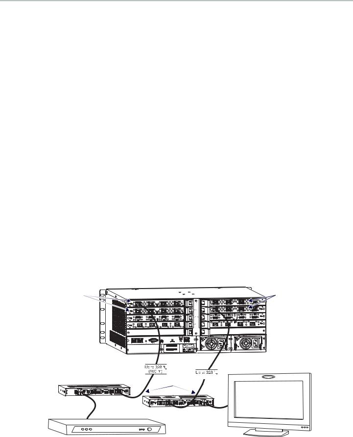
Installation and Setup
Setup Requirements
A PC with NetLinx Studio v4.0 or later installed.
An understanding of which DXLink Mode the system will be used in (see below and page 31). An understanding of the DIP switch settings (see page 36).
When used with an Enova DGX Digital Media Switcher the system’s power requirements must be determined (see page 31).
When used with an Enova DVX Solution – The SEND_COMMANDs for enabling network activity (Ethernet traffic) over the DXLink line must be used (see page 81).
IMPORTANT: We recommend that DXLink equipment be installed by a technician with knowledge of networks and experience with NetLinx Studio and its Telnet interface. NetLinx experience should include changing device addresses, binding devices, updating firmware, etc.
The remainder of the “Setup Information” section covers information for system setup, power budget planning, network loop concerns, binding to an integrated Master, DIP switch settings, mounting options, chassis grounding, cable requirements and recommendations (including RJ-45 pinouts and LED behavior), and audio type precedence.
The specific installation’s requirements dictate the system setup, which generally takes one of the following three forms.
Endpoint Mode (Switcher) – One or more Transmitters and/or Receivers are connected to a switcher* containing a Master (see below).
Endpoint Mode (Standalone) – A standalone DXLink TX/RX pair are connected directly to each other but, in addition, either the TX or RX is connected to a NetLinx Central Controller via a LAN or directly to the Controller (see page 30).
Extender Mode (Standalone) – A standalone DXLink TX/RX pair are connected directly to each other as a simple extender solution (see page 31).
* The switcher can be either an Enova DGX Switcher or an applicable Enova DVX Solution (see “Product Compatibility Tables” on page 8).
Endpoint Mode (Switcher): Example of Typical System Setup
The primary function of the Transmitters and Receivers is to work with compatible DXLink equipment as an endpoint solution for transmission of HDMI over twisted pair cable (or DVI-D signals with the use of a DVI-to-HDMI cable adapter, or analog video signals through a DX-TX, Wallplate TX, or Decor Wallplate TX).
The Transmitter receives an HDMI signal and an audio signal from a source device. The audio can be either digital audio embedded with the HDMI signal, digital audio over S/PDIF (S/PDIF is not available on the Wallplate TX or Decor Wallplate TX), or analog stereo audio. Both the video and embedded audio are transmitted over twisted pair cable to the RJ-45 connector on the DXLink Input Board. The HDMI signal is then routed through any (or all) of the connectors on one or more output boards.
When the HDMI signal is routed through a DXLink Output connector to a Receiver, the Receiver sends the HDMI signal with embedded audio on to the destination device. The audio can also be output on the Receiver’s stereo audio port.
In systems where DXLink Transmitters and Receivers are used in conjunction with a switcher (e.g., Enova DGX 16), the cable runs from a Transmitter to a DXLink Input Board and from a DXLink Output Board to a Receiver can each be up to 328 feet (100 m).
DXLink Input |
DXLink Output |
Boards |
Boards |
Destination device
DXLink HDMI Transmitter Twisted pair cable
Source device |
DXLink HDMI Receiver |
|||
|
||||
|
|
|
|
|
FIG. 13 Endpoint Mode (Switcher) setup with Enova DGX 16
Hardware Reference Manual – DXLink Twisted Pair™ Transmitters/Receiver |
28 |
|
|
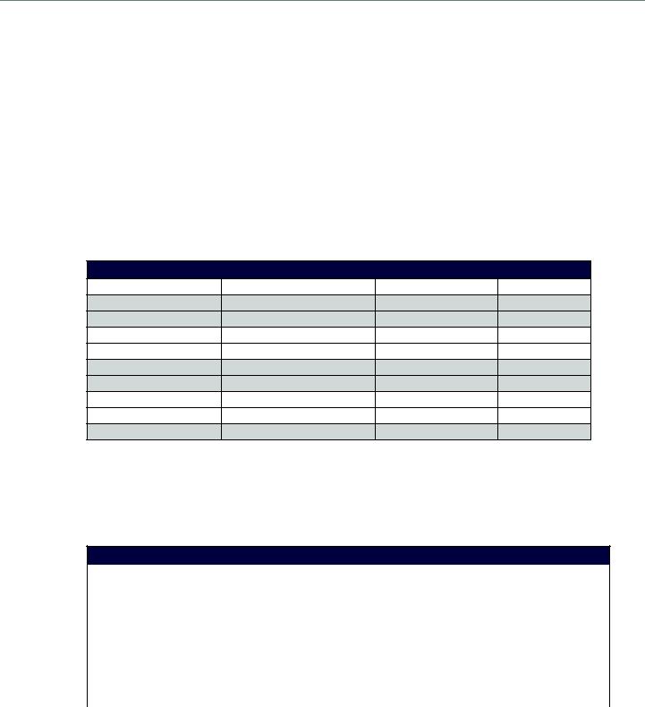
Installation and Setup
TIP: For systems with special requirements – Before installing in the final location, place the equipment close together, so that the destination monitor and a PC for control can be seen simultaneously if adjustments are necessary. Scaling adjustments can be made using SEND_COMMANDs (see page 64). For Enova DGX 8/16/32/64 Switchers, DGX Configuration Software can also be used to make scaling adjustments via the switcher (see the switcher’s manual). For Enova DGX 100 Series Switchers, scaling can also be adjusted via the System Configuration interface (see the switcher’s manual).
CAUTION: Be careful not to create a network (Ethernet) loop. To avoid doing so, see page 33.
Custom EDID Settings
If Transmitters are part of an Enova DGX system which requires custom EDID settings, see the switcher’s manual for information on the EDID programming functionality in DGX Configuration Software (available at www.amx.com). SEND_COMMANDs can also be used (see page 64).
If Receivers are part of an Enova DGX 8/16/32/64 system which requires scaler control and settings, see the switcher’s manual for information on the scaling functionality in DGX Configuration Software (available at www.amx.com). SEND_COMMANDs can also be used (see page 64).
Options for System Setup with Enova DGX DXLink Boards
The following table contains options for using DXLink Transmitters and Receivers in conjunction with DXLink Twisted Pair Input and Output Boards in an Enova DGX Digital Media Switcher.
System Setup Options – Enova DGX DXLink Boards with DXLink Transmitters/Receivers
DXLink Module/Wallplate |
Input Board |
Output Board |
DXLink Module |
DX-TX Module |
DXLink Twisted Pair |
DXLink Twisted Pair |
DX-RX Module |
DX-TX Module |
DXLink Twisted Pair |
Any board* |
Not applicable |
HDMI TX Module |
DXLink Twisted Pair |
DXLink Twisted Pair |
DX-RX Module |
HDMI TX Module |
DXLink Twisted Pair |
Any board * |
Not applicable |
Wallplate TX |
DXLink Twisted Pair |
DXLink Twisted Pair |
DX-RX Module |
Wallplate TX |
DXLink Twisted Pair |
Any board* |
Not applicable |
Decor Wallplate TX |
DXLink Twisted Pair |
DXLink Twisted Pair |
DX-RX Module |
Decor Wallplate TX |
DXLink Twisted Pair |
Any board* |
Not applicable |
Not Applicable |
Any board* |
DXLink Twisted Pair |
DX-RX Module |
* If the board is an SC Optical Board in an Enova DGX Digital Media Switcher, it will need the appropriate DGX Fiber Module. For information, see the DGX Fiber Module’s manual.
Options for System Setup with Enova DVX Solutions
The following table contains options for using DXLink Transmitters and Receivers in conjunction with DXLink Input and Output connectors on Enova DVX Solutions. Note that on the input side, four Transmitter options are available. The Transmitters used with the inputs can be of the same type or different, depending on the installation needs.
Unless otherwise indicated, the Enova DVX Solutions in the table below have 2 DXLink input and/or output connectors.
System Setup Options – Enova DVX DXLink Solutions with DXLink Transmitters/Receivers
DXLink Module/Wallplate Options |
Enova DVX Solution |
DXLink Module |
||
|
|
|
|
|
|
DVX-3155HD |
......................................... |
||
...................................................... |
DVX-2155HD** |
|||
|
DVX-3156HD*** |
|
||
DX-TX Module |
|
|
|
|
HDMI TX Module |
DXLink Input connector |
DXLink Output connector |
DX-RX Module |
|
Wallplate TX |
||||
|
|
|
||
Decor Wallplate TX |
|
|
|
|
...................................................... |
DVX- |
2150HD** |
......................................... |
|
|
|
|
|
|
NA |
NA |
DXLink Output connector |
DX-RX Module |
|
|
|
|
|
|
**These Enova DVX models have 1 DXLink output connector each.
***The Enova DVX-3156HD has 4 DXLink inputs and 2 DXLink outputs.
Hardware Reference Manual – DXLink Twisted Pair™ Transmitters/Receiver |
29 |
|
|
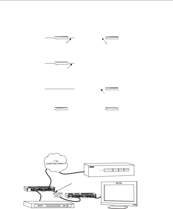
Installation and Setup
Functions of DXLink Transmitters and Receivers
The diagram in FIG. 14 shows the functions of DXLink Transmitters and Receivers. The example descriptions contain the device HDCP key count when used in conjunction with DXLink Boards in an Enova DGX Digital Media Switcher and when using a Transmitter and Receiver as a standalone pair.
Example A |
|
|
|
|
Switcher |
|
|
|
|
|
|
|
|
TX acts like a sink |
|
|
RX acts like a source |
|
|||||||
Source |
|
|
Destination |
|||||||||
HDMI |
|
|
|
DXLink In |
DXLink |
|
|
|
|
|
||
|
|
|
|
|
|
|
|
HDMI |
|
|||
|
|
|
|
|
|
|
|
|
|
|
||
|
cable |
|
|
|
|
|
|
|
|
|
cable |
|
|
Twisted pair cable |
Twisted pair cable |
|
|||||||||
|
|
|
|
|||||||||
Example B |
|
|
|
|
Switcher |
|
|
|
|
|
|
|
|
TX acts like a sink |
|
|
|
|
|
|
|
|
|||
Source |
|
|
|
|
|
|
|
Destination |
||||
|
|
|
|
DXLink |
HDMI Out |
|
|
|
|
|
||
|
HDMI |
|
|
|
|
HDMI cable |
|
|
||||
|
|
|
|
|
|
|
|
|
||||
|
cable |
|
|
|
|
|
|
|
|
|
|
|
|
Twisted pair cable |
|
|
|
|
|
|
|
||||
|
|
|
|
|
|
|
|
|
||||
Example C |
|
|
|
|
Switcher |
|
|
|
|
|
|
|
|
|
|
|
|
Acts like |
|
RX acts like a source |
|
||||
|
|
|
|
|
|
|
||||||
Source |
|
|
|
|
a sink |
|
Destination |
|||||
|
|
|
|
|
HDMI In |
DXLink |
|
|
|
|
|
|
|
HDMI cable |
|
|
|
|
HDMI |
|
|||||
|
|
|
|
|
|
|||||||
|
|
|
|
|
|
|
|
|||||
|
|
|
|
|
|
|
|
cable |
|
|||
|
|
|
|
|
|
Twisted pair cable |
|
|||||
Example D |
|
|
|
|
|
|
|
|
|
|
|
|
|
TX acts like a repeater |
|
RX acts like a repeater |
|
||||||||
Source |
|
Destination |
||||||||||
|
|
|
|
|
|
|
|
|
|
|
||
|
HDMI |
|
|
|
Twisted pair cable |
|
|
|
|
HDMI |
|
|
|
|
|
|
|
|
|
|
|
|
cable |
|
|
|
cable |
|
|
|
|
|
|
|
|
|
|
|
|
|
|
|
|
|
|
|
|
|
|
|
|
Example A: When a Receiver acts like a source, its key does not count. Source device sees 1 key (Transmitter). Example B: When a Transmitter acts like a sink, the source device sees 1 key (Transmitter).
Example C: When a source device is connected directly to a switcher, the source sees 1 key (switcher input). Example D: When a Transmitter is part of a standalone pair, its key does not count. Source device sees 2 keys.
FIG. 14 Repeater and source functions of TX/RX Modules (A, B, D also apply to Wallplate TX and Decor Wallplate TX)
Endpoint Mode (Standalone): Example of Typical System Setup
A standalone DXLink TX/RX pair are connected directly to each other but, in addition, either the TX or RX is connected to a NetLinx Central Controller via a LAN or directly to the Controller.
NetLinx Central Controller
DXLink |
Destination device |
|
Twisted pair cable |
||
Transmitter |
||
|
||
|
DXLink Receiver |
|
|
Source device |
|
FIG. 15 Endpoint Mode (Standalone) with NetLinx Central Controller |
||
Hardware Reference Manual – DXLink Twisted Pair™ Transmitters/Receiver |
30 |
|
|
Loading...