


 Loading...
Instruction Manual
Octaire
Distribution Matrix
Matrix Switchers |
Release: 08/15/2008 |
AMX Limited Warranty and Disclaimer
All products returned to AMX require a Return Material Authorization (RMA) number. The RMA number is obtained from the AMX RMA Department. The RMA number must be clearly marked on the outside of each box. The RMA is valid for a 30-day period. After the 30-day period the RMA will be cancelled. Any shipments received not consistent with the RMA, or after the RMA is cancelled, will be refused. AMX is not responsible for products returned without a valid RMA number.
Warranty Repair Policy
•AMX will repair any defect due to material or workmanship issues during the applicable warranty period at no cost to the AMX Authorized Partner, provided that the AMX Authorized Partner is responsible for in-bound freight and AMX is responsible for outbound ground freight expenses.
•The AMX Authorized Partner must contact AMX Technical Support to validate the failure before pursuing this service.
•AMX will complete the repair and ship the product within five (5) business days after receipt of the product by AMX. The AMX Authorized Partner will be notified if repair cannot be completed within five (5) business days.
•Products repaired will carry a ninety (90) day warranty or the balance of the remaining warranty, whichever is greater.
•Products that are returned and exhibit signs of damage or unauthorized use will be processed under the Non-Warranty Repair Policy.
•AMX will continue to provide Warranty Repair Services for products discontinued or replaced by a Product Discontinuance Notice.
Non-Warranty Repair Policy
•Products that do not qualify to be repaired under the Warranty Repair Policy due to age of the product or Condition of the product may be repaired utilizing this service.
•The AMX Authorized Partner must contact AMX Technical Support to validate the failure before pursuing this service.
•Non-warranty repair is a billable service.
•Products repaired under this policy will carry a ninety (90) day warranty on material and labor.
•AMX will notify the AMX Authorized Partner with the cost of repair, if cost is greater than the Standard Repair Fee, within five (5) days of receipt.
•The AMX Authorized Partner must provide a Purchase Order or credit card number within five (5) days of notification, or the product will be returned to the AMX Authorized Partner.
•The AMX Authorized Partner will be responsible for in-bound and out-bound freight expenses.
•Products will be repaired within ten (10) business days after AMX Authorized Partner approval is obtained.
•Non-repairable products will be returned to the AMX Authorized Partner with an explanation.
•See AMX Non-Warranty Repair Price List for minimum and Standard Repair Fees and policies.
Software License and Warranty Agreement
•LICENSE GRANT. AMX grants to Licensee the non-exclusive right to use the AMX Software in the manner described in this License. The AMX Software is licensed, not sold. This license does not grant Licensee the right to create derivative works of the AMX Software. The AMX Software consists of generally available programming and development software, product documentation, sample applications, tools and utilities, and miscellaneous technical information. Please refer to the README.TXT file on the compact disc or download for further information regarding the components of the AMX Software. The AMX Software is subject to restrictions on distribution described in this License Agreement. AMX Dealer, Distributor, VIP or other AMX authorized entity shall not, and shall not permit any other person to, disclose, display, loan, publish, transfer (whether by sale, assignment, exchange, gift, operation of law or otherwise), license, sublicense, copy, or otherwise disseminate the AMX Software. Licensee may not reverse engineer, decompile, or disassemble the AMX Software.
•ACKNOWLEDGEMENT. You hereby acknowledge that you are an authorized AMX dealer, distributor, VIP or other AMX authorized entity in good standing and have the right to enter into and be bound by the terms of this Agreement.
•INTELLECTUAL PROPERTY. The AMX Software is owned by AMX and is protected by United States copyright laws, patent laws, international treaty provisions, and/or state of Texas trade secret laws. Licensee may make copies of the AMX Software solely for backup or archival purposes. Licensee may not copy the written materials accompanying the AMX Software.
•TERMINATION. AMX RESERVES THE RIGHT, IN ITS SOLE DISCRETION, TO TERMINATE THIS LICENSE FOR ANY REASON UPON WRITTEN NOTICE TO LICENSEE. In the event that AMX terminates this License, the Licensee shall return or destroy all originals and copies of the AMX Software to AMX and certify in writing that all originals and copies have been returned or destroyed.
•PRE-RELEASE CODE. Portions of the AMX Software may, from time to time, as identified in the AMX Software, include PRERELEASE CODE and such code may not be at the level of performance, compatibility and functionality of the GA code. The PRE-RELEASE CODE may not operate correctly and may be substantially modified prior to final release or certain features may not be generally released. AMX is not obligated to make or support any PRE-RELEASE CODE. ALL PRE-RELEASE CODE IS PROVIDED “AS IS” WITH NO WARRANTIES.
•LIMITED WARRANTY. AMX warrants that the AMX Software (other than pre-release code) will perform substantially in accordance with the accompanying written materials for a period of ninety (90) days from the date of receipt. AMX DISCLAIMS ALL OTHER WARRANTIES, EITHER EXPRESS OR IMPLIED, INCLUDING, BUT NOT LIMITED TO IMPLIED WARRANTIES OF MERCHANTABILITY AND FITNESS FOR A PARTICULAR PURPOSE, WITH REGARD TO THE AMX SOFTWARE. THIS LIMITED WARRANTY GIVES LICENSEE SPECIFIC LEGAL RIGHTS. Any supplements or updates to the AMX SOFTWARE, including without limitation, any (if any) service packs or hot fixes provided to Licensee after the expiration of the ninety (90) day Limited Warranty period are not covered by any warranty or condition, express, implied or statutory.
•LICENSEE REMEDIES. AMX's entire liability and Licensee's exclusive remedy shall be repair or replacement of the AMX Software that does not meet AMX's Limited Warranty and which is returned to AMX in accordance with AMX's current return policy. This Limited Warranty is void if failure of the AMX Software has resulted from accident, abuse, or misapplication. Any replacement AMX Software will be warranted for the remainder of the original warranty period or thirty (30) days, whichever is longer.
Outside the United States, these remedies may not available. NO LIABILITY FOR CONSEQUENTIAL DAMAGES. IN NO EVENT SHALL AMX BE LIABLE FOR ANY DAMAGES WHATSOEVER (INCLUDING, WITHOUT LIMITATION, DAMAGES FOR LOSS OF BUSINESS PROFITS, BUSINESS INTERRUPTION, LOSS OF BUSINESS INFORMATION, OR ANY OTHER PECUNIARY LOSS) ARISING OUT OF THE USE OF OR INABILITY TO USE THIS AMX SOFTWARE, EVEN IF AMX HAS BEEN ADVISED OF THE POSSIBILITY OF SUCH DAMAGES. BECAUSE SOME STATES/COUNTRIES DO NOT ALLOW THE EXCLUSION OR LIMITATION OF LIABILITY FOR CONSEQUENTIAL OR INCIDENTAL DAMAGES, THE ABOVE LIMITATION MAY NOT APPLY TO LICENSEE.
•U.S. GOVERNMENT RESTRICTED RIGHTS. The AMX Software is provided with RESTRICTED RIGHTS. Use, duplication, or disclosure by the Government is subject to restrictions as set forth in subparagraph ©(1)(ii) of The Rights in Technical Data and Computer Software clause at DFARS 252.227-7013 or subparagraphs ©(1) and (2) of the Commercial Computer Software Restricted Rights at 48 CFR 52.227-19, as applicable.
•SOFTWARE AND OTHER MATERIALS FROM AMX.COM MAY BE SUBJECT TO EXPORT CONTROL. The United States Export Control laws prohibit the export of certain technical data and software to certain territories. No software from this Site may be downloaded or exported (i) into (or to a national or resident of) Cuba, Iraq, Libya, North Korea, Iran, Syria, or any other country to which the United States has embargoed goods; or (ii) anyone on the United States Treasury Department's list of Specially Designated Nationals or the U.S. Commerce Department's Table of Deny Orders. AMX does not authorize the downloading or exporting of any software or technical data from this site to any jurisdiction prohibited by the United States Export Laws.
This Agreement replaces and supersedes all previous AMX Software License Agreements and is governed by the laws of the State of Texas, and all disputes will be resolved in the courts in Collin County, Texas, USA. For any questions concerning this Agreement, or to contact AMX for any reason, please write: AMX License and Warranty Department, 3000 Research Drive, Richardson, TX 75082.

|
Contents |
Contents |
|
ESD Warning ....................................................................................................... |
1 |
Important Safety Information & Instructions ....................................................... |
2 |
Information et directives de sécurité importantes............................................... |
3 |
Notices ................................................................................................................ |
4 |
Overview & General Specifications ..................................................................... |
7 |
Applicability Notice ................................................................................................................. |
7 |
Product Notes ......................................................................................................................... |
9 |
Front View............................................................................................................................. |
11 |
Rear View .............................................................................................................................. |
11 |
General Specifications ........................................................................................................... |
13 |
External Control Options....................................................................................................... |
14 |
Installation & Setup ........................................................................................... |
15 |
Site Recommendations .......................................................................................................... |
15 |
General Hazard Precautions .................................................................................................. |
15 |
Unpacking.............................................................................................................................. |
16 |
Rack Installation & System Setup .......................................................................................... |
17 |
Linking Enclosures ................................................................................................................. |
19 |
Attaching Inputs & Outputs................................................................................................... |
21 |
Attaching External Control.................................................................................................... |
24 |
Applying Power & Startup..................................................................................................... |
27 |
Executing a Test Switch......................................................................................................... |
30 |
Technical Support.................................................................................................................. |
31 |
Cabling & Setup for Vertical Interval Sync............................................................................. |
32 |
Connecting to the APWeb Server ......................................................................................... |
35 |
Signal Types & Specifications ............................................................................ |
39 |
Video Signals......................................................................................................................... |
39 |
Stereo Audio Signals ............................................................................................................. |
41 |
Octaire Control Panel Operation....................................................................... |
43 |
Overview ............................................................................................................................... |
43 |
Executing Switches................................................................................................................ |
47 |
Changing Virtual Matrices (Routing Levels) ........................................................................... |
49 |
Disconnecting Switches ......................................................................................................... |
50 |
Verifying Signal Status........................................................................................................... |
51 |
Defining & Executing Global Presets..................................................................................... |
52 |
Adjusting Audio..................................................................................................................... |
54 |
Locking & Unlocking.............................................................................................................. |
58 |
Setup Options ....................................................................................................................... |
60 |
System Error Codes & Troubleshooting ................................................................................ |
65 |
Octaire Instruction Manual |
i |
|
|

Contents |
|
APWeb – Initial Setup by Network Admin........................................................ |
67 |
Overview ............................................................................................................................... |
67 |
Opening the APWeb Server .................................................................................................. |
68 |
Overview of the Admin Home Page ...................................................................................... |
69 |
Setting a Static IP Address .................................................................................................... |
70 |
Using a DHCP IP Address (Optional) ..................................................................................... |
70 |
Setting Admin & User Account Logins................................................................................... |
71 |
Executing a Test Switch with the XBar .................................................................................. |
72 |
Executing a Test Switch with BCS.......................................................................................... |
73 |
Customizing the Site.............................................................................................................. |
74 |
Customizing Bootup Operations ........................................................................................... |
75 |
Customizing the Control Options .......................................................................................... |
76 |
Defining Routing Levels (Manually Configuring VMs) ............................................................ |
78 |
Handling Security Issues ........................................................................................................ |
80 |
Opening a Telnet Session ...................................................................................................... |
81 |
Executing & Disconnecting Switches ..................................................................................... |
82 |
Adjusting Audio Settings....................................................................................................... |
83 |
Executing Macros .................................................................................................................. |
85 |
APWeb – Controlling the Octaire ..................................................................... |
87 |
Connecting to APWeb ........................................................................................................... |
87 |
Home Page ............................................................................................................................ |
88 |
Executing & Disconnecting Switches ..................................................................................... |
88 |
Executing Macros .................................................................................................................. |
91 |
APWeb – Additional Info for Network Admin .................................................. |
92 |
Embedding the XBar Applet ................................................................................................. |
92 |
Changing the Proxy Setting................................................................................................... |
93 |
Appendix A – Octaire AutoPatch Connector Guide.......................................... |
96 |
Appendix B – Programmer’s Interface for System Diagnostics......................... |
97 |
System Component Information ............................................................................................ |
97 |
ii |
Octaire Instruction Manual |

ESD Warning
ESD Warning
To avoid ESD (Electrostatic Discharge) damage to sensitive components, make sure you are properly grounded before touching any internal materials.
When working with any equipment manufactured with electronic devices, proper ESD grounding procedures must be followed to ensure people, products, and tools are as free of static charges as possible. Grounding straps, conductive smocks, and conductive work mats are specifically designed for this purpose.
Anyone performing field maintenance on AMX AutoPatch equipment should use an appropriate ESD field service kit complete with at least a dissipative work mat with a ground cord and a UL listed adjustable wrist strap with another ground cord. These items should not be manufactured locally, since they are generally composed of highly resistive conductive materials to safely drain static charges, without increasing an electrocution risk in the event of an accident. ESD protective equipment can be obtained from 3M™, Desco®, Richmond Technology®, Plastic Systems®, and other such vendors.
Octaire Instruction Manual |
1 |
|
|

Important Safety Information & Instructions
Important Safety Information & Instructions
When using and installing your AMX AutoPatch product, adhere to the following basic safety precautions. For more information about operating, installing, or servicing your AMX AutoPatch product see your product documentation.
Read and understand all instructions before using and installing AMX AutoPatch products. Use the correct voltage range for your AMX AutoPatch product.
There are no user serviceable parts inside an AMX AutoPatch product; service should only be done by qualified personnel.
If you see smoke or smell a strange odor coming from your AMX AutoPatch product, turn it off immediately and call technical support.
For products with multiple power supplies in each unit, make sure all power supplies are turned on simultaneously.
Use surge protectors and/or AC line conditioners when powering AMX AutoPatch products. Only use a fuse(s) with the correct fuse rating in your enclosure.
Make sure the power outlet is close to the product and easily accessible. Make sure the product is on or attached to a stable surface.
Turn off equipment before linking pieces together, unless otherwise specified in that product's documentation.
For safety and signal integrity, use a grounded external power source and a grounded power connector.
To avoid shock or potential ESD (Electrostatic Discharge) damage to equipment, make sure you are properly grounded before touching components inside an AMX AutoPatch product.
2 |
Octaire Instruction Manual |

Information et directives de sécurité importantes
Information et directives de sécurité importantes
Veuillez vous conformer aux directives de sécurité ci-dessous lorsque vous installez et utilisez votre appareil AMX AutoPatch. Pour de plus amples renseignements au sujet de l’installation, du fonctionnement ou de la réparation de votre appareil AMX AutoPatch, veuillez consulter la documentation accompagnant l’appareil.
Lisez attentivement toutes les directives avant d’installer et d’utiliser les appareils AMX AutoPatch.
Le voltage doit être approprié à l'appareil AMX AutoPatch.
Les appareils AMX AutoPatch ne contiennent aucune pièce réparable par l’usager; la réparation ne doit être effectuée que par du personnel qualifié.
Si de la fumée ou une odeur étrange se dégagent d’un appareil AMX AutoPatch, fermez-le immédiatement et appelez le Service de soutien technique.
Veillez à ce que tous les blocs d’alimentation des appareils dotés de blocs d’alimentation multiples dans chaque unité soient allumés simultanément.
Servez-vous de protecteurs de surtension ou de conditionneurs de lignes à courant alternatif lorsque vous mettez les appareils AMX AutoPatch sous tension.
Placez uniquement des fusibles de calibre exact dans les boîtiers.
Veillez à ce que la prise de courant soit proche de l’appareil et facile d’accès.
Veillez à ce que votre appareil AMX AutoPatch soit installé sur une surface stable ou qu’il y soit fermement maintenu.
Fermez toutes les composantes de l’équipement avant de relier des pièces, à moins d’indication contraire fournie dans la documentation de l’appareil.
Par mesure de sécurité et pour la qualité des signaux, servez-vous d’une source d’alimentation externe mise à la terre et d’un connect d’alimentation mis à la terre.
Pour éviter les chocs ou les dommages éventuels causés à l’équipement par une décharge électrostatique, veillez à ce le dispositif oit bien relié à la terre avant de toucher les composantes se trouvant à l’intérieur d’un appareil AMX AutoPatch.
Octaire Instruction Manual |
3 |
|
|

Notices
Notices
Copyright Notice
AMX© 2008 (Rev: A), all rights reserved. No part of this publication may be reproduced, stored in a retrieval system, or transmitted, in any form or by any means, electronic, mechanical, photocopying, recording, or otherwise, without the prior written permission of AMX. Copyright protection claimed extends to AMX hardware and software and includes all forms and matters copyrightable material and information now allowed by statutory or judicial law or herein after granted, including without limitation, material generated from the software programs which are displayed on the screen such as icons, screen display looks, etc. Reproduction or disassembly of embodied computer programs or algorithms is expressly prohibited.
No patent liability is assumed with respect to the use of information contained herein.
Liability Notice
While every precaution has been taken in the preparation of this publication, AMX assumes no responsibility for error or omissions. No liability is assumed for damages resulting from the use of the information contained herein.
Further, this publication and features described herein are subject to change without notice.
USFCC Notice
The United States Federal Communications Commission (in 47CFR 15.838) has specified that the following notice be brought to the attention of the users of this product.
Federal Communication Commission Radio Frequency Interference Statement:
“This equipment has been tested and found to comply with the limits for a Class A digital device, pursuant to Part 15 of the FCC Rules. These limits are designed to provide reasonable protection against harmful interference when the equipment is operated in a commercial environment. This equipment generates, uses, and can radiate radio frequency energy and, if not installed and used in accordance with the instruction manual, may cause harmful interference to radio communications. Operation of this equipment in a residential area is likely to cause harmful interference in which case the user will be required to correct the interference at his own expense.
If necessary, the user should consult the dealer or an experienced radio/television technician for additional suggestions. The user may find the booklet, How to Identify and Resolve Radio-TV Interference Problems, prepared by the Federal Communications Commission to be helpful.”
This booklet is available from the U.S. Government Printing Office, Washington, D.C. 20402, Stock N. 004-000-00345-4.
Use shielded cables. To comply with FCC Class A requirement, all external data interface cables and adapters must be shielded.
Lithium Batteries Notice
Switzerland requires the following notice for products equipped with lithium batteries. This notice is not applicable for all AMX equipment.
Upon shipment of the products to Switzerland, the requirements of the most up-to-date Swiss Ordinance Annex 4.10 of SR 814.013 will be met by providing the necessary documents and annual reports relative to the disposal of the batteries to the Swiss Authorities.
4 |
Octaire Instruction Manual |
Notices
Trademark Notices
AMX®, AutoPatch®, Octaire™, Ultra-Flat Response Certified™, and NetLinx® are trademarks of AMX.
Windows®, Windows 98®, Windows 2000®, Windows NT®, and Windows XP Professional® are registered trademarks of Microsoft Corporation.
HyperTerminal® is a copyright product of Hilgraeve Inc.
3M™, Desco®, Richmond Technology®, and Plastic Systems® are registered trademarks. Neuron® and LonTalk® are registered trademarks of Echelon.
TosLink® is a registered trademark of the Toshiba Corporation. Ethernet® is a registered trademark of the Xerox Corporation.
Other products mentioned herein may be the trademarks of their respective owners.
Warnings & Cautions
This manual uses the following conventions and icons to draw attention to actions or conditions that could potentially cause problems with equipment or lead to personal risk.
ESD Warning: The icon to the left indicates text regarding potential danger associated with the discharge of static electricity from an outside source (such as human hands) into an integrated circuit, often resulting in damage to the circuit.
Warning: The icon to the left indicates text that cautions readers against actions or conditions that could cause potential injury to themselves.
Caution: The icon to the left indicates text that cautions readers against actions that could cause potential injury to the product or the possibility of serious inconvenience.
Octaire Instruction Manual |
5 |
|
|
Notices
6 |
Octaire Instruction Manual |

Overview & General Specifications
Overview & General Specifications
The Octaire Distribution Matrix is a fixed system consisting of a single video or audio enclosure or multiple video enclosures with or without audio in a fixed input/output range. Because the Octaire is available in various fixed sizes, the illustrations in this manual may differ slightly from model(s) you purchased. These cost-effective, off-the-shelf units pack the same high-performance specifications as our other top lines.
Applicability Notice
In the following five tables, enclosures are designated as:
STD – standard video
UWB – ultra-wideband video
SYNC – digital HV sync
AUDIO – stereo audio
The designations for the video type are on labels on the rear of the enclosures.
An explanation for the model numbers is provided in FIG. 1.
FIG. 1 Octaire model numbers
Composite Video and Composite Video+Stereo:
Model |
Configuration |
Description |
# of Enclosures |
FGP44-3248-110 |
32x48 |
Composite Video |
1 STD |
|
|
|
|
FGP44-3264-110 |
32x64 |
Composite Video |
1 STD |
|
|
|
|
FGP44-4832-110 |
48x32 |
Composite Video |
1 STD |
|
|
|
|
FGP44-4848-110 |
48x48 |
Composite Video |
1 STD |
|
|
|
|
FGP44-4864-110 |
48x64 |
Composite Video |
1 STD |
|
|
|
|
FGP44-6432-110 |
64x32 |
Composite Video |
1 STD |
|
|
|
|
FGP44-6448-110 |
64x48 |
Composite Video |
1 STD |
|
|
|
|
FGP44-6464-110 |
64x64 |
Composite Video |
1 STD |
|
|
|
|
FGP44-3248-117 |
32x48 |
Composite Video+Stereo |
1 STD + 1 AUDIO |
|
|
|
|
FGP44-3264-117 |
32x64 |
Composite Video+Stereo |
1 STD + 1 AUDIO |
|
|
|
|
FGP44-4832-117 |
48x32 |
Composite Video+Stereo |
1 STD + 1 AUDIO |
|
|
|
|
FGP44-4848-117 |
48x48 |
Composite Video+Stereo |
1 STD + 1 AUDIO |
|
|
|
|
FGP44-4864-117 |
48x64 |
Composite Video+Stereo |
1 STD + 1 AUDIO |
|
|
|
|
FGP44-6432-117 |
64x32 |
Composite Video+Stereo |
1 STD + 1 AUDIO |
|
|
|
|
FGP44-6448-117 |
64x48 |
Composite Video+Stereo |
1 STD + 1 AUDIO |
|
|
|
|
FGP44-6464-117 |
64x64 |
Composite Video+Stereo |
1 STD + 1 AUDIO |
|
|
|
|
Octaire Instruction Manual |
7 |
|
|

Overview & General Specifications
Y/c and Y/c+Stereo:
Model |
Configuration |
Description |
# of Enclosures |
FGP44-3248-210 |
32x48 |
Y/c |
2 STD |
|
|
|
|
FGP44-3264-210 |
32x64 |
Y/c |
2 STD |
|
|
|
|
FGP44-4832-210 |
48x32 |
Y/c |
2 STD |
|
|
|
|
FGP44-4848-210 |
48x48 |
Y/c |
2 STD |
|
|
|
|
FGP44-4864-210 |
48x64 |
Y/c |
2 STD |
|
|
|
|
FGP44-6432-210 |
64x32 |
Y/c |
2 STD |
|
|
|
|
FGP44-6448-210 |
64x48 |
Y/c |
2 STD |
|
|
|
|
FGP44-6464-210 |
64x64 |
Y/c |
2 STD |
|
|
|
|
FGP44-3248-217 |
32x48 |
Y/c+Stereo |
2 STD + 1 AUDIO |
|
|
|
|
FGP44-3264-217 |
32x64 |
Y/c+Stereo |
2 STD + 1 AUDIO |
|
|
|
|
FGP44-4832-217 |
48x32 |
Y/c+Stereo |
2 STD + 1 AUDIO |
|
|
|
|
FGP44-4848-217 |
48x48 |
Y/c+Stereo |
2 STD + 1 AUDIO |
|
|
|
|
FGP44-4864-217 |
48x64 |
Y/c+Stereo |
2 STD + 1 AUDIO |
|
|
|
|
FGP44-6432-217 |
64x32 |
Y/c+Stereo |
2 STD + 1 AUDIO |
|
|
|
|
FGP44-6448-217 |
64x48 |
Y/c+Stereo |
2 STD + 1 AUDIO |
|
|
|
|
FGP44-6464-217 |
64x64 |
Y/c+Stereo |
2 STD + 1 AUDIO |
|
|
|
|
Component and Component+Stereo:
Model |
Configuration |
Description |
# of Enclosures |
FGP44-3248-360 |
32x48 |
Component |
3 UWB |
|
|
|
|
FGP44-3264-360 |
32x64 |
Component |
3 UWB |
|
|
|
|
FGP44-4832-360 |
48x32 |
Component |
3 UWB |
|
|
|
|
FGP44-4848-360 |
48x48 |
Component |
3 UWB |
|
|
|
|
FGP44-4864-360 |
48x64 |
Component |
3 UWB |
|
|
|
|
FGP44-6432-360 |
64x32 |
Component |
3 UWB |
|
|
|
|
FGP44-6448-360 |
64x48 |
Component |
3 UWB |
|
|
|
|
FGP44-6464-360 |
64x64 |
Component |
3 UWB |
|
|
|
|
FGP44-3248-367 |
32x48 |
Component+Stereo |
3 UWB + 1 Audio |
|
|
|
|
FGP44-3264-367 |
32x64 |
Component+Stereo |
3 UWB + 1 Audio |
|
|
|
|
FGP44-4832-367 |
48x32 |
Component+Stereo |
3 UWB + 1 Audio |
|
|
|
|
FGP44-4848-367 |
48x48 |
Component+Stereo |
3 UWB + 1 Audio |
|
|
|
|
FGP44-4864-367 |
48x64 |
Component+Stereo |
3 UWB + 1 Audio |
|
|
|
|
FGP44-6432-367 |
64x32 |
Component+Stereo |
3 UWB + 1 Audio |
|
|
|
|
FGP44-6448-367 |
64x48 |
Component+Stereo |
3 UWB + 1 Audio |
|
|
|
|
FGP44-6464-367 |
64x64 |
Component+Stereo |
3 UWB + 1 Audio |
|
|
|
|
8 |
Octaire Instruction Manual |

|
|
|
Overview & General Specifications |
||
RGBHV and RGBHV+Stereo: |
|
|
|
|
|
|
|
|
|
|
|
Model |
Configuration |
Description |
# of Enclosures |
|
|
FGP44-3248-560 |
32x48 |
RGBHV |
3 UWB + 2 SYNC |
|
|
|
|
|
|
|
|
FGP44-3264-560 |
32x64 |
RGBHV |
3 UWB + 2 SYNC |
|
|
|
|
|
|
|
|
FGP44-4832-560 |
48x32 |
RGBHV |
3 UWB + 2 SYNC |
|
|
|
|
|
|
|
|
FGP44-4848-560 |
48x48 |
RGBHV |
3 UWB + 2 SYNC |
|
|
|
|
|
|
|
|
FGP44-4864-560 |
48x64 |
RGBHV |
3 UWB + 2 SYNC |
|
|
|
|
|
|
|
|
FGP44-6432-560 |
64x32 |
RGBHV |
3 UWB + 2 SYNC |
|
|
|
|
|
|
|
|
FGP44-6448-560 |
64x48 |
RGBHV |
3 UWB + 2 SYNC |
|
|
|
|
|
|
|
|
FGP44-6464-560 |
64x64 |
RGBHV |
3 UWB + 2 SYNC |
|
|
|
|
|
|
|
|
FGP44-3248-567 |
32x48 |
RGBHV+Stereo |
3 UWB + 2 SYNC + 1 AUDIO |
|
|
|
|
|
|
|
|
FGP44-3264-567 |
32x64 |
RGBHV+Stereo |
3 UWB + 2 SYNC + 1 AUDIO |
|
|
|
|
|
|
|
|
FGP44-4832-567 |
48x32 |
RGBHV+Stereo |
3 UWB + 2 SYNC + 1 AUDIO |
|
|
|
|
|
|
|
|
FGP44-4848-567 |
48x48 |
RGBHV+Stereo |
3 UWB + 2 SYNC + 1 AUDIO |
|
|
|
|
|
|
|
|
FGP44-4864-567 |
48x64 |
RGBHV+Stereo |
3 UWB + 2 SYNC + 1 AUDIO |
|
|
|
|
|
|
|
|
FGP44-6432-567 |
64x32 |
RGBHV+Stereo |
3 UWB + 2 SYNC + 1 AUDIO |
|
|
|
|
|
|
|
|
FGP44-6448-567 |
64x48 |
RGBHV+Stereo |
3 UWB + 2 SYNC + 1 AUDIO |
|
|
|
|
|
|
|
|
FGP44-6464-567 |
64x64 |
RGBHV+Stereo |
3 UWB + 2 SYNC + 1 AUDIO |
|
|
|
|
|
|
|
|
Stereo: |
|
|
|
|
|
|
|
|
|
|
|
Model |
Configuration |
Description |
# of Enclosures |
|
|
FGP44-3248-007 |
32x48 |
Stereo |
1 AUDIO |
|
|
|
|
|
|
|
|
FGP44-3264-007 |
32x64 |
Stereo |
1 AUDIO |
|
|
|
|
|
|
|
|
FGP44-4832-007 |
48x32 |
Stereo |
1 AUDIO |
|
|
|
|
|
|
|
|
FGP44-4848-007 |
48x48 |
Stereo |
1 AUDIO |
|
|
|
|
|
|
|
|
FGP44-4864-007 |
48x64 |
Stereo |
1 AUDIO |
|
|
|
|
|
|
|
|
FGP44-6432-007 |
64x32 |
Stereo |
1 AUDIO |
|
|
|
|
|
|
|
|
FGP44-6448-007 |
64x48 |
Stereo |
1 AUDIO |
|
|
|
|
|
|
|
|
FGP44-6464-007 |
64x64 |
Stereo |
1 AUDIO |
|
|
|
|
|
|
|
|
Product Notes
Octaire fixed matrix switchers are designed for large, analog, high performance applications. The configuration for an Octaire system (whether single enclosure or multi-enclosure) is set at the factory. Octaire 4 RU enclosures each route one signal type. Four enclosure types, each handling a single signal, support all of the system combinations listed in the previous tables.
Enclosures
Standard video enclosure (quantity 1) – supports a composite video signal
Standard video enclosures (quantity 2) – support a Y/c signal (Y in one and c in the other)
Ultra-wideband enclosure (quantity 3) – supports a single component of a three-component (HDTV) signal
Ultra-wideband enclosures (quantity 3) – support an “R,” “G,” or “B” component of an RGBHV signal
Digital sync enclosures (quantity 2) – support an HV sync signal (H in one and V in the other) Audio enclosure (quantity 1) – supports a stereo audio signal
Octaire Instruction Manual |
9 |
|
|

Overview & General Specifications
Because the video enclosures look identical, it is crucial that they are cabled according to the labels on the rear and the “Octaire AutoPatch Connector Guide” (see page 96), which is included in the shipment (also see “Linking Enclosures” on page 19).
Note: On a multi-enclosure system, the primary enclosure is the one with a control panel (and a TCP/IP port) and is the point of control for the system.
Octaire Features
Ultra-Flat Response Certified (bandwidth curve measured at a tight +/-3 dB)
Ultra-wideband video bandwidth for UWB enclosures in any routing state, including fully loaded – averaging 600 MHz, while maintaining 500 MHz at the ultra-flat response certified minimum
High bandwidth-linearity and low crosstalk
Detection, Assignment, and Configuration (DAC) firmware that automatically recognizes and configures each enclosure, sequences them, and generates a united, single feature solution
Switch any input to any or all outputs in any combination and disconnect any or all outputs Breakaway to route video, audio, or audio-follow-video
Global presets
Vertical interval synchronization of video signals Dual power feeds and redundant power supplies Standard RS-232
Service Access Spacing (twice the space between connectors) – making BNC cable connections easy
Standard Warranty (see warranty at www.amx.com or on the AMX AutoPatch CD) 24-hour technical support
Octaire Control Features
In addition to the front control panel (standard with all Octaire systems), which is mounted on the primary enclosure, several control options are available. Multiple control methods can be used on the same system.
NetLinx® compatible and supports Device Discovery (for specific control programming information, contact your AMX representative)
APControl 3.0 software (free with all systems) APWeb (TCP/IP control)
Supports AMX AutoPatch’s simple BCS* (Basic Control Structure) serial control protocol Supports AMX AutoPatch’s XNNet protocol
Supports third-party controllers
* BCS is sent as ASCII characters through the RS-232 port.
Important: Device Discovery functionality (beacon response) will only function properly if the NetLinx master is connected to the RS-232 control port on the primary enclosure (the one with the control panel). The RS-232 ports on the secondary enclosures are intended for single enclosure diagnostic information and system firmware upgrades.
Features and specifications described in this document are subject to change without notice.
10 |
Octaire Instruction Manual |

Overview & General Specifications
Front View
A front control panel is standard with each system and is mounted on the primary enclosure. The panel is used for controlling the system’s switches and system attributes. For complete control panel information, see the “Control Panel” chapter on page 43.
LCD |
Control Dial |
Input Keys |
Function Key |
Take Key |
Output Keys |
|
Cancel Key |
Select Key |
Power Indicator |
|
FIG. 2 Front view of 64x64 Octaire enclosure
Rear View
The enclosure’s appearance, as viewed from the rear, will vary depending on the signal/connector types and the configuration size (which is also the main determinate of weight).
Control hardware (CPU) |
Input connectors |


 Output connectors
Serial number |
Power receptacles & switches |
FIG. 3 Rear view of 48x48 Octaire video enclosure
Rear View Components
Control hardware (CPU)
Power receptacles with switches
Serial number
Input and output connectors
Octaire Instruction Manual |
11 |
|
|
Overview & General Specifications
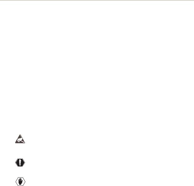
Control Hardware
TCP/IP port (RJ-45)
VIS toggle switches
VIS connectors (BNC) |


 System Status indicator


 Serial port (DB-9)


 Linking ports (RJ-45)
FIG. 4 Control hardware on primary enclosure
The control hardware (CPU) on the primary enclosure is on the right and includes the following: TCP/IP port (on primary enclosure only) – for connecting to an APWeb Server (page 35) Set of toggle switches – for setting the vertical interval sync parameters (page 33)
Two BNC connectors – for linking vertical interval sync (page 32)
System Status indicator – for system power and communication status (page 28)
Serial port (DB-9) – for attaching an external control device to the primary enclosure (page 25) Two linking ports (RJ-45) – for linking multi-enclosure Octaire systems (page 19)
The hardware (CPU) on the secondary enclosure(s) is also on the right and includes the same items as the primary enclosure, except it does not have a TCP/IP port and LEDs. The serial port on secondary enclosures is intended for single enclosure diagnostic information and system firmware upgrades.
Power Receptacles & Switches


 Power 1 switch & receptacle


 Power requirements


 Power 2 switch & receptacle
FIG. 5 Power supplies receptacles and switches
The Octaire has dual power connections for the redundant power supplies located on the left. Each power supply has a power receptacle with a switch and will accept all major international standard power sources. Two standard US power cords are provided for installations within the US. The maximum power specifications are located between the power receptacles. For additional information on the redundant power supplies, see page 27.
Serial Number
The serial number is located on the rear next to the power receptacles (see FIG. 3 on page 11).
We recommend recording the “FGP44-xxxx-xxx” system number (see page 7) and the serial number for each enclosure in the system in an easily accessible location.
12 |
Octaire Instruction Manual |
Overview & General Specifications
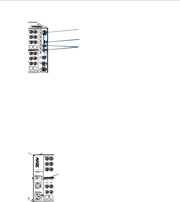
Input & Output Connectors
Service Access Spacing between connectors (twice the space for easy cable connections)
Input connectors |


 Output connectors
FIG. 6 Input & output connectors
Viewed from the rear of the enclosure, the connectors span the center from the power receptacles to the control area with the inputs on the top with the outputs directly below. Input and output connectors are the attachment points for source and destination devices that connect to the system. The rear of each enclosure is populated with connectors for a single signal type (for configuration sizes, see the “Applicability Notice” on page 7 through page 9). Inputs and outputs are numbered separately. The numbers are above each connector and read left to right, continuing on the next row of connectors. All video connectors are BNC, and audio connectors are 5-position terminal block. For systems containing video enclosures, we recommend installing a color-coded band representing the enclosure’s signal type on the first input BNC connector on each enclosure. A set of colored bands ships with the system; for the colored band to signal correspondence, see the table on page 22.
For cabling and wiring information for each signal type, see page 21. For signal specifications, see page 39.
General Specifications
Specifications
Approvals |
CE, UL, cUL |
|
|
|
|
AC Power |
100 to 240 VAC single phase (50 to 60 Hz) |
|
|
3.3 A @ 115 VAC max. |
|
|
1.6 A @ 230 VAC max. |
|
|
|
|
Power Consumption (max.) |
260 |
W per enclosure |
|
|
|
Power Consumption (typical) |
120 |
W per enclosure, fully loaded |
|
|
|
Operational Temperature |
32° to 113° F (0° to 45° C) |
|
|
|
|
Thermal Dissipation (max.) |
887 |
BTU/hour |
|
|
|
Thermal Dissipation (typical) |
409 |
BTU/hour, fully loaded enclosure |
|
|
|
Humidity |
0 to 90% non-condensing |
|
|
|
|
Enclosure Dimensions |
Approximately 12.0 in. (30.5 cm) depth (including connectors) |
|
|
18.9 in. (48.0 cm) width with mounting ears |
|
|
17.4 in. (44.2 cm) width without mounting ears |
|
|
6.95 in. (17.65 cm) height, 4 RU |
|
|
|
|
Weight |
Approximately 20 lbs. (9.07 kg) per enclosure (depending on configuration) |
|
|
Approximately 24 lbs. (10.89 kg) packaged for shipping |
|
|
|
|
Octaire Instruction Manual |
13 |
|
|

Overview & General Specifications
External Control Options
Note: The Octaire has a fixed configuration that was set at the factory.
Octaire systems are controlled with either the control panel (page 43) or externally with one of the following options:
NetLinx®
The Octaire is NetLinx® compatible. For specific control programming information, contact your AMX representative.
Control Software
Octaire systems can be controlled using AMX AutoPatch software: APControl 3.0 – Control and scheduling
Uses serial port located on the primary enclosure’s far right when viewed from the rear Runs on a PC connected to the serial port
Download* from the AMX AutoPatch CD
APWeb Server – Control, diagnostics, and third-party access
TCP/IP port located on the primary enclosure’s far right when viewed from the rear Accessed through a TCP/IP interface such as a web browser (e.g., Internet Explorer)
Contact AMX regarding limitations and conditions for operating an Octaire on a company LAN (Local Area Network)
* If your AMX account has the required permissions, you can download APControl from www.amx.com.
BCS Serial Control Protocol
An Octaire system can be controlled with an external serial controller connected to the primary enclosure. AMX AutoPatch has developed a command language, BCS* (Basic Control Structure) protocol, for programming control operations and for diagnostic purposes.
External Serial Controllers – Control using BCS protocol Serial Control (sends and receives ASCII characters)
Uses serial port located on the primary enclosure’s far right when viewed from the rear
Commands can be entered into a terminal emulation program on a PC connected to the serial port (such as Windows® HyperTerminal)
*For information on BCS commands, see the BCS Protocol Instruction Manual on the
AMX AutoPatch CD or at www.amx.com.
Third-Party Controllers
A third-party controller can also be attached to an Octaire enclosure via the RS-232 serial port on the primary enclosure. If using a third-party controller, see the controller documentation for operating instructions.
14 |
Octaire Instruction Manual |

Installation & Setup
Installation & Setup
Site Recommendations
When placing the enclosure, follow the recommendations and precautions in this section to reduce potential installation and operation hazards. For general specifications, see page 13; for individual signal specifications, see the “Signal Types & Specifications” chapter (page 39).
Environment
Choose a clean, dust free, (preferably) air-conditioned location.
Avoid areas with direct sunlight, heat sources, or high levels of EMI (Electromagnetic
Interference).
Chassis Accessibility
Make sure the front and rear panels of the enclosure are accessible, so that you can monitor the LED indicators. Leaving adequate clearance at the rear will also allow for easier cabling and service.
Power
The source’s electrical outlet should be installed near the router, easily accessible, and properly grounded. Power should come from a building branch circuit. We recommend that a second, independent branch be used for the second AC inlet feed to the enclosure (see page 27). Use a minimum breaker current rating of 30 A for 110 V or 15 A for 230 V.
To avoid an overload, note the power consumption rating of all the equipment connected to the circuit breaker before applying power.
General Hazard Precautions
These recommendations address potential hazards that are common to all installations:
Elevated Operating Temperature
The maximum rated ambient temperature for Octaire enclosures is 113° F (45° C).
All equipment should be installed in an environment compatible with the manufacturer’s maximum rated ambient temperature. In a closed or multi-unit rack assembly, the operating ambient temperature of the rack environment may be greater than the ambient room temperature.
Caution: To protect the equipment from overheating, do not operate in an area that exceeds 113° (45° C) and follow the clearance recommendation below for adequate airflow.
Airflow Restriction
Octaire enclosures are designed to adequately dissipate the heat they produce under normal operating conditions; however, this design is defeated when high heat-producing equipment is placed directly above or below an enclosure.
Caution: To prevent overheating, avoid placing high heat-producing equipment directly above or below the enclosure. The system requires a minimum of one empty rack unit above and below (three empty rack units are recommended). Verify that the openings on the sides of the enclosure are not blocked and do not have restricted air flow.
Octaire Instruction Manual |
15 |
|
|
Installation & Setup
Mechanical (Rack) Loading
When installing equipment in a rack, distribute the weight to avoid uneven mechanical loading.
Circuit Overloading
When connecting the equipment to the supply circuits, be aware of the effect that overloading the circuits might have on over-current protection and supply wiring.
Reliable Earthing (Grounding)
Reliable earthing of rack-mounted equipment should be maintained. If not using a direct connection to the branch circuit (e.g., plugging into a power strip), pay particular attention to supply connections.
Note: We recommend attaching all power cords to surge protectors and/or AC line conditioners (see page 27). After powering up the enclosure, apply power to the source and destination devices.
Unpacking
The Octaire is shipped with one enclosure per shipping box. The invoice is sent separately; a packing list is attached to the outside of each box. Each box contains the following items:
Enclosure
2 standard US power cords (if shipped within the US) Rack ears and screws
Link cable provided with multi-enclosure systems Other enclosure products, as needed
The documentation in the first box includes:
AMX AutoPatch Octaire Quick Start Guide
AMX Octaire AutoPatch Connector Guide Custom label kit
Color rings for connectors to indicate type of video enclosure(s)
AMX AutoPatch CD
For orders comprising multiple enclosures, the shipping boxes are marked as “Chassis __ of __,” where the first blank is the box number and the second blank is the total number of boxes in the shipment.
Unpacking Tips
Before fully unpacking the enclosure(s), examine the shipping box(es) for any signs of damage. If a box is partially crushed or any sides have been broken open, notify the shipping agency immediately and contact your AMX representative (see the warranty on the AMX AutoPatch CD or at www.amx.com).
Once unpacking is complete, closely check the physical condition of the enclosure. Collect all documentation.
Note: Please save the original shipping container and packing materials. AMX is not responsible for damage caused by insufficient packing during return shipment to the factory. Shipping boxes are available; contact your AMX representative for details.
16 |
Octaire Instruction Manual |

Installation & Setup
Rack Installation & System Setup
Octaire Distribution Matrix enclosures fit in a standard EIA 19 in. (48.26 cm) rack (rack ears are provided).
Important: The system requires at least one empty rack unit above and below the enclosure to allow adequate airflow; three empty rack units are recommended.
Required items for rack installation:
Enclosure(s) Rack ears
Standard EIA 19 in. (48.26 cm) rack Screwdriver
Screws that fit your rack for mounting the enclosure(s) Power cords (2 per enclosure)
Link cables (provided with multi-enclosure systems) Surge-protectors – recommended
Optional items for rack installation
PC or laptop computer with a null modem cable (for communication with the Octaire via the RS-232 serial port on the primary enclosure)
Installation Recommendations
Write the serial number for each enclosure (located on the rear next to the power receptacles) in an easily accessible location before installing the Octaire in a rack.
Use earth-grounded power cords / system with the Octaire.
Attach all power cords (see FIG. 19 on page 27) to surge protector(s) and/or AC line conditioner(s).
Apply power to the Octaire enclosure(s) before applying power to its source and destination devices.
Installation Procedure
A flow chart showing the installation sequence is in FIG. 7. The procedure, which follows on page 18, provides general steps with references to detailed information found in later sections of the manual.
FIG. 7 Installation procedure
Caution: To prevent overheating and airflow restriction, avoid placing high heat-producing equipment directly above or below the enclosure. The system requires a minimum of one empty rack unit above and below (three empty rack units are recommended). Verify that the openings on the sides of the enclosure are not blocked and do not have restricted air flow.
Octaire Instruction Manual |
17 |
|
|
Installation & Setup
To install and set up an Octaire system in a rack:
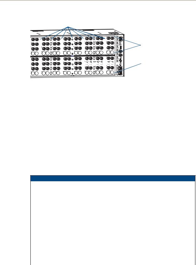
1.Attach rack ears per FIG. 8.
FIG. 8 Attach rack ears
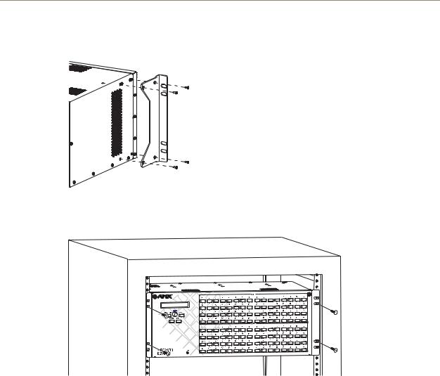
2.Place the enclosure in the rack and attach front-mounting screws to hold it firmly in place (FIG. 9); repeat for any additional enclosures.
FIG. 9 Place enclosure(s) in rack and secure with screws
Tip: When placing enclosures, keep in mind that the optimal viewing angle for a control panel is eye level.
3.Multi-enclosure systems – Link the enclosures together; see “Linking Enclosures” on page 19.
4.Optional – Establish communication with an external control device/system; see “Attaching External Control” on page 24. For TCP/IP information, see “Connecting to the APWeb Server” on page 35.
5.Attach only the first source device and the first destination device; see “Attaching Inputs & Outputs” on page 21. Multiple BNC connectors attached to corresponding connectors on the enclosures designated on the “Octaire AutoPatch Connector Guide” (page 96) are required for all video signals except composite.
Do not apply power to the source and destination devices until after the Octaire has power (Step 7).
Tip: Using lacer bars or some other type of cable management system lessens the strain from cable weight on the connectors and makes servicing the Octaire easier.
6.If applicable – Connect cables for vertical interval sync (VIS) signals; see “Cabling & Setup for Vertical Interval Sync” on page 32.
7.Apply power to the system according to the power-up procedure; see “Applying Power & Startup” on page 27.
Note: We recommend using surge protectors and/or AC line conditioners (see page 27).
18 |
Octaire Instruction Manual |
Installation & Setup
8.Execute a test switch to ensure the system is working properly; see “Executing a Test Switch” on page 30.
9.When the test switch works correctly, attach the remaining source and destination devices.
Additional Installation Options
Additional installation tasks may include the following:
Setting a control panel password – See the “Control Panel Operations” chapter (page 62) Labeling input and output keys – See the “Control Panel Operations” chapter (page 46) Creating global presets – See the BCS Protocol Instruction Manual on the
AMX AutoPatch CD or at www.amx.com
Linking Enclosures
Important: An Octaire Distribution Matrix is a fixed system. Do not link an Octaire enclosure to another type of AMX AutoPatch enclosure or to another Octaire enclosure which is not part of its factory-defined system.
Linking enclosures in a multi-enclosure system allows control information to pass between them with the LINK (RJ-45) ports providing consistent control speed.
In a multi-enclosure Octaire system, the enclosure with the control panel (referred to as the primary enclosure) receives control information (from the control panel or an external controller) and passes on relevant information to the other enclosures via the links as well as retrieving control requests for success/failure from each of them.
Caution: AMX AutoPatch systems can only be linked in their own isolated networks.
Link Cable Requirements
Octaire enclosures link directly to each other via the two LINK ports (RJ-45) at the lower right using the crossover cables that are provided. (Straight-through cable can also be used for linking. If straightthrough cable is used, use it consistently between all enclosures in the system.)
Crossover Cable Specifications
Wiring – Wired to TIA / EIA-568-A on one end and TIA / EIA-568-B on the other end Length – Maximum length is 100 ft. (30.5 m)
Caution: Enclosures must be cabled correctly after linking. To ensure that you are attaching the correct signal cables to the correct enclosure, check the labels designating the signal type on the rear of the enclosure and the “Octaire AutoPatch Connector Guide” (page 96).
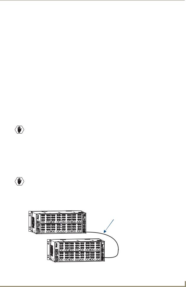
Linking Two Octaire Enclosures:
Link two Octaire enclosures together via the LINK (RJ-45) ports using the provided crossover cable.
Link cable – crossover or straight-through
Length of provided crossover cable: 3 ft. (0.9 m)
FIG. 10 Link two Octaire enclosures with the provided cable or up to 100 ft. (30.5 m) apart |
|
Octaire Instruction Manual |
19 |
Installation & Setup
To link two Octaire enclosures:
1.Insert one end of the crossover cable into the lower LINK port on the primary enclosure (the one with the control panel).
2.Insert the other end of the crossover cable into the upper LINK port on the secondary enclosure.
When power is applied, the LINK connector LEDs illuminate indicating communication status between enclosures (see FIG. 12 on page 21).
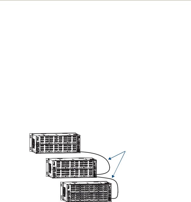
Linking Three or More Octaire Enclosures
In a multi-enclosure system, link the Octaire enclosures together in a daisy chain via the LINK (RJ-45) ports using the provided crossover cables.
Each video enclosure has a label that designates the signal type on the rear:
STD (standard video) – supports composite signals or the Y or c components of Y/c signals
UWB (ultra-wideband) – supports three-component signals or the R, G, or B components of RGBHV signals
SYNC (digital sync) – supports the H or V components of RGBHV signals
Start with the primary enclosure (the one with the control panel) for the first video component type (e.g., R for RGBHV). Secondary enclosures of the same signal type (e.g., G and B or H and V) are interchangeable. Link the remaining enclosures according to the “Octaire AutoPatch Connector Guide” (see page 96) and to the signal type labels on the rear of the enclosures. The audio enclosure is always last.
Link cable – crossover or straight-through (be consistent)
Length of provided crossover cables: 3 ft. (0.9 m)
FIG. 11 Use the LINK ports to link enclosures with the provided cable or up to 100 ft. (30.5 m) apart
To link three or more Octaire enclosures:
1.Insert one end of the crossover cable into the lower LINK port on the primary enclosure (the one with the control panel).
2.Insert the other end of the crossover cable into the upper LINK port on the second enclosure.
3.For each additional enclosure in the system, attach crossover cables connecting from one enclosure’s LINK port to the next until all enclosures in the system are linked together according to the “Octaire AutoPatch Connector Guide” (page 96).
When power is applied, the LINK connector LEDs illuminate indicating communication status between enclosures (see FIG. 12).
20 |
Octaire Instruction Manual |
Installation & Setup
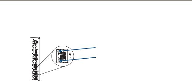
LINK Connector LEDs
The LINK (RJ-45) connectors are 10Base-T and have two LEDs that indicate communication status when the enclosure is linked and active.
Amber LED “on” – link status is active
Green LED “blinks” – activity between enclosures |
FIG. 12 LINK (RJ-45) connector LEDs
Note: The Status LED indicator directly above the DB-9 port on the enclosure’s rear indicates system status.
Attaching Inputs & Outputs
Input and output connectors are the attachment points for source and destination devices that connect to the system. Viewed from the rear of an Octaire enclosure, the input connectors are in the center on the top with the output connectors directly below them. Input and output connectors are numbered separately. The numbers are above each connector and read left to right, continuing on the next row of connectors. The configuration of the system determines the number of connectors.
An “Octaire AutoPatch Connector Guide” (see page 96) is included with the primary enclosure to ensure correct routing. The system is programmed to operate based on the guide.
Cabling Video Connectors
All video connectors are BNC. For the BNC connectors on Octaire enclosures, the upper set (inputs) is white and the lower set (outputs) is black. For signal specifications for standard video, ultra-wideband video, and sync video, see the “Signal Types & Specifications” chapter (page 39).
Video Types
The available video types for the Octaire are Composite
Y/c Three-component/HDTV RGBHV
Signal Type Labels on Enclosures
Important: Be sure to attach the video cables to the correct enclosure. Octaire enclosures are built and programmed at the factory to handle specific signal types. This is especially important for enclosure systems that contain both ultra-wideband and digital sync enclosures because the enclosures look the same, but they do not support the same signal type.
The enclosures have labels designating the signal type on the rear of each enclosure:
STD (standard video) – supports composite signals or the Y or c components of Y/c signals
UWB (ultra-wideband) – supports three-component signals or the R, G, or B components of RGBHV signals
SYNC (digital sync) – supports the H and V components of RGBHV signals
Octaire Instruction Manual |
21 |
|
|
Installation & Setup
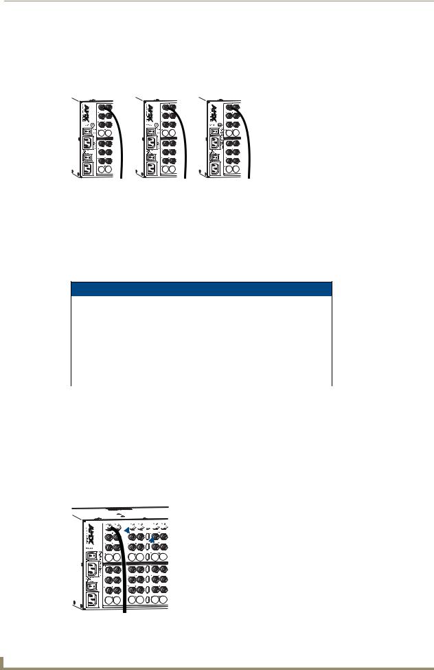
Depending on the signal type (e.g., component signals), you may need to attach corresponding input and output connectors on more than one enclosure to route the entire signal. For example, FIG. 13 shows three BNC cable connectors attached for routing a three-component signal through Input 1. Follow the “Octaire AutoPatch Connector Guide” (page 96) to ensure correct routing.
Y |
Pb |
Pr |
Enclosure 1 |
Enclosure 2 |
Enclosure 3 |
FIG. 13 Three BNC connectors are required for a three-component signal
Installing Color Bands for Signal Types
Before attaching input and output video cables, we recommend installing the applicable color band (a set of colored bands ship with the system) on the first input BNC connector of each enclosure. The color bands help to easily identify the signal type supported by each enclosure when attaching input and output cables and when linking multiple-enclosure systems.
For the signal type to colored band correspondence, see the table below.
Signal Type – Color of Band
RGB (UWB) |
Y/Pb/Pr (UWB) |
Y/c (STD) |
Composite (STD) |
R = Red |
Y = Green |
Y = Yellow |
V = Yellow |
G = Green |
Pb = Blue |
C = Black |
|
B = Blue |
Pr = Red |
|
|
HV (SYNC) |
|
|
|
H = White |
|
|
|
V = Black |
|
|
|
|
|
|
|
Connecting Video Cables
Before connecting all input and output video cables (and, if applicable, wires for stereo), attach the cables (and wires) for the first source and first destination devices only and execute a test switch (see page 30). When the test switch is successful, attach the rest of the input and output cables (and wires).
Tip: Using lacer bars or some other type of cable management system lessens the strain from cable weight on the connectors and makes servicing the Octaire easier.
To connect video inputs and outputs:
1.Fasten the cables onto the input and output BNC connectors (FIG. 14).


 Service Access Spacing between connectors
Tip: Cable up or down using the waterfall method to take advantage of the Service Access Spacing feature on the Octaire.
|
FIG. 14 Fasten cables onto input and output BNC connectors |
22 |
Octaire Instruction Manual |
Installation & Setup
Wiring Stereo Audio Connectors (5-position terminal block)
The stereo audio connectors for the Octaire are pluggable 5-position terminal block. For stereo audio signal specifications, see the “Signal Types & Specifications” chapter (page 39). If full stereo is not required, mono audio can be used; wire either the left or right channel for all inputs and outputs.
Wiring Sources & Destinations
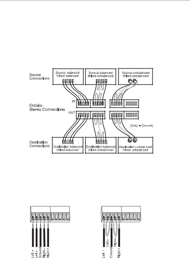
Source and destination devices will require either balanced (differential) or unbalanced (single-ended) connections. FIG. 15 illustrates options for wiring between sources and input connectors and between output connectors and the destinations. More than one option can be used in the same system. For balanced and unbalanced wiring details, see FIG. 16.
FIG. 15 Options for source-to-Octaire-to-destination 5-Term wiring
Attaching Wires
To attach stereo audio input and output wires:
1.Unscrew the clamps on the audio connector.
2.Insert the wires and firmly re-tighten the clamps to make secure connections. For balanced audio wire placement, see the left wiring diagram in FIG. 16. For unbalanced audio wire placement, see the right wiring diagram in FIG. 16.
FIG. 16 Balanced audio |
Unbalanced audio |
Note: For stereo audio signals using twisted pair wire, connect the shield (ground) only at one end (recommend receiving end) to minimize low frequency noise.
Octaire Instruction Manual |
23 |
|
|

Installation & Setup
Attaching External Control
Note: The Octaire has a fixed configuration that was programmed at the factory.
The Octaire can be controlled externally by attaching a control device that uses one of the communication protocols listed below:
BCS (Basic Control Structure) – ASCII sent over a null modem serial cable via RS-232 XNNet – AMX AutoPatch protocol via RS-232
TCP/IP – See “Connecting to the APWeb Server” on page 35
In a multi-enclosure Octaire system, only the primary enclosure (with control panel) is enabled for external control via the serial port or TCP/IP port. Serial ports on secondary enclosures are primarily intended for single enclosure diagnostic information and system firmware upgrades.
Control Options
The communication protocols listed above are used for these control options:
NetLinx®
AMX AutoPatch distribution matrices are NetLinx® compatible and support Device Discovery. For specific control programming information, contact your AMX representative.
Important: Device Discovery functionality (beacon response) will only function properly if the NetLinx master is connected to the RS-232 control port on the primary enclosure (the one with the control panel).
APControl 3.0
APControl 3.0 software (for control and scheduling) runs on a PC connected to an Octaire via the serial port (DB-9) on the primary enclosure and is available on the AMX AutoPatch CD.
APWeb (TCP/IP)
The APWeb server (for control, diagnostics, and third-party access) is accessed through a TCP/IP interface such as a web browser (e.g., Internet Explorer). The Octaire TCP/IP port is used to access APWeb. For connecting to the APWeb server, see page 35. For APWeb Server setup and operation information, see the “APWeb – Initial Setup by Network Admin” chapter on page 67 and the “APWeb – Controlling the Octaire” chapter (page 87).
Important: Contact AMX regarding limitations and conditions for operating an Octaire on a company LAN.
XNNet Protocol (Serial)
Advanced programmers who want to design their own control programs can use AMX AutoPatch XNNet protocol. The AMX AutoPatch CD includes the XNNet Communication Library, an interface library that supports C, Java, and Visual Basic with examples of the XNNet protocol in use.
BCS (Serial) Control
AMX AutoPatch has developed a command language, BCS (Basic Control Structure), for executing control operations and for diagnostic purposes. BCS commands are issued via a terminal emulation program, such as Windows® HyperTerminal. For information on BCS commands, see the BCS Protocol Instruction Manual on the AMX AutoPatch CD and at www.amx.com.
Third-Party Controllers (Serial)
Third-party controllers connect to the serial port (DB-9) on the right rear of the primary enclosure.
If using a third-party controller, see the controller documentation for setup and operating instructions.
24 |
Octaire Instruction Manual |
Installation & Setup
Connecting Serial Controllers
An external serial controller is any device that can send and receive ASCII code over an RS-232 (null modem) serial cable attached to the serial port (DB-9) on the right rear of the primary enclosure.
PCs are common serial controllers. Once a PC is attached to the Octaire, the system can be controlled by running APControl software on the attached PC (see the AMX AutoPatch CD). The system can also be controlled by entering BCS commands into a terminal emulation program (e.g., HyperTerminal). For information on BCS commands, see the BCS Protocol Instruction Manual on the AMX AutoPatch CD and at www.amx.com.
PC Requirements for APControl 3.0
Windows XP Professional® or Windows 2000®
Java Runtime Environment (JRE): v1.4.2 or the latest version
Minimum Hardware: 166 MHz, 128 MB RAM, 20 MB free disk space, 800x600 display
Recommended Hardware: 2.0 GHz, 512 MB RAM, 20 MB free disk space, 1280x1024 display
Serial port
PC Requirements for BCS
Windows XP Professional® or Windows 2000®
Terminal emulation program (e.g., HyperTerminal)
Serial port
Connecting an External Serial Controller
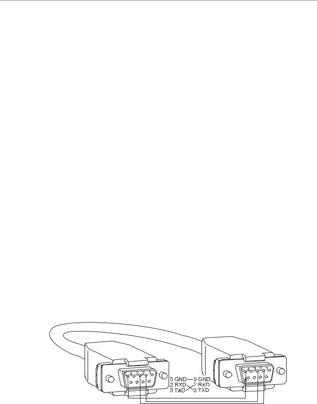
Use a null modem cable that matches the pin diagram in FIG. 17 for RS-232 without hardware flow control. AMX AutoPatch equipment requires pins 2, 3, and 5 only.
The Octaire is tested with a manufactured cable to a maximum length of 100 ft. (30.5 m). The maximum length of null modem cable that can be used in specific systems will vary according to the quality of the cable.
RS-232 Pin Diagram
FIG. 17 RS-232 pin diagram (no hardware flow control)
Octaire Instruction Manual |
25 |
|
|
Loading...