


AMS Asset Monitor
Online Prediction, Protection, and Process Monitor
Installation Guide
MHM-97923-PBF, Rev 2.5
June 2022

Copyright
©
2022 by Emerson. All rights reserved.
No part of this publication may be reproduced, transmitted, transcribed, stored in a retrieval system, or translated into any
language in any form by any means without the written permission of Emerson.
Disclaimer
This manual is provided for informational purposes. EMERSON MAKES NO WARRANTY OF ANY KIND WITH REGARD TO THIS
MATERIAL, INCLUDING, BUT NOT LIMITED TO, THE IMPLIED WARRANTIES OF MERCHANTABILITY AND FITNESS FOR A PARTICULAR
PURPOSE. Emerson shall not be liable for errors, omissions, or inconsistencies that may be contained herein or for incidental or
consequential damages in connection with the furnishing, performance, or use of this material. Information in this document is
subject to change without notice and does not represent a commitment on the part of Emerson. The information in this manual is
not all-inclusive and cannot cover all unique situations.
Patents
The product(s) described in this manual are covered under existing and pending patents.
Vermerk zur Installation der Messketten in explosionsgefährdeter Umgebung.
Soll die Messkette in explosionsgefährdeter Umgebung installiert werden, so ist auf die Einhaltung der in der
Gebrauchsanweisung enthaltenen Installationshinweise zu achten. Sollten dabei sprachliche Schwierigkeiten
auftreten, wenden Sie sich bitte an die Herstellerfirma, sie wird Ihnen eine Übersetzung der relevanten Artikel in der
Landessprache des Verwendungslandes zukommen lassen.
Nota fuq l−installazzjoni tal−ktajjen tal−kejl f’ambjent esplożiv
Jekk il−katina tal−kejl suppost li tigi installata f’ambjent esplożiv, hu importanti li ssegwi l−istruzzjonijiet pertinenti
tal−manwal.Jekk issib xi diffikultà bil−lingwa, jekk joghgbok ikkuntattja lill−manifattur biex tikseb traduzz-joni tal
−paragrafi rilevanti fil−lingwa mehtiega.
Anmärkning beträffande installation av mätkedjorna i explosionsfarlig miljö.
Ska mätkedjan installeras i explosionsfarlig miljö, måste de anvisningar följas som ges i instruktionsboken
beträffande installationen. Skulle därvid språkproblem uppstå, ber vi dig kontakta det tillverkande företaget som
då kommer att sända dig en översättning av de relevanta artiklarna på användningslandets språk.
Opomba za namestitev merilne verige v eksplozivno ogroženem okolju
Èe se merilna veriga namešèa v eksplozivno ogroženem okolju, je potrebno upoštevati namestitvena opozorila, ki
so v Navodilih za uporabo. Èe se pri tem pojavijo jezikovne težave, se posvetujte z izdelovalcem; poslali vam bodo
prevod ustreznih èlankov v jeziku države, kjer se naprava uporablja.
Záznam k inštalácii meracích reťazcov vo výbušnom prostredí
Ak má byť merací reťazec inštalovaný vo výbušnom prostredí, treba dbať na dodržiavanie pokynov k inštalácii,
uvedených v návode na použitie. V prípade, že by sa pritom vyskytli jazykové problémy, obráťte sa prosím na
výrobcu, ktorý Vám zašle preklad relevantných èlánkov v jazyku Vašej krajiny.
Nota referente à instalação de cadeias de agrimensor em ambientes potencialmente explosivos
Caso a cadeia de agrimensor deva ser instalada em um ambiente potencialmente explosivo, é imprescindível
observar e cumprir as indicações de instalação das instruções de serviço. Caso tenha dificuldades idiomáticas,
queira entrar em contato com a firma produtora, esta poderá enviar−lhe uma tradução dos capítulos mais
importantes no idioma do país onde o produto deverá ser empregado.
Wskazówka dotycząca instalacji łańcuchów mierniczych w otoczeniach zagrożonych eksplozją.
Jeżeli łańcuch mierniczy ma być zainstalowany w otoczeniu zagrożonym eksplozją, należy uwzględnić wskazówki
dotyczące instalacji, które są zawarte w instrukcji obsługi. Jeżeli w trakcie lektury wystąpią jakiekolwiek problemy
związane ze zrozumieniem tekstu, prosimy zwrócić się do producenta, który chętnie wykona tłumaczenie
wybranych części dokumentacji na język danego kraju.
2

Opmerking m.b.t. installatie van elektrische meet circuits in explosiegevaarlijke omgeving
Dient de installatie van elektrische meet circuits in een explosiegevaarlijke omgeving te geschieden, moet men
toezien dat de in de gebruikshandleiding opgenomen installatieinstructies worden nageleefd. Bij taalkundige
problemen gelieve contact op te nemen met de fabrikant, deze zal u vervolgens een vertaling in de taal van het
gebruiksland doen toekomen.
Pastaba dėl matavimo grandinės įrengimo sprogimo atžvilgiu pavojingoje aplinkoje
Jei matavimo grandinė turi būti įrengta sprogimo atžvilgiu pavojingoje aplinkoje, privaloma laikytis vartotojo
instrukcijoje pateiktų įrengimo nurodymų. Jei kiltų sunkumų dėl kalbos, prašome kreiptis į gamintojo įmonę, kuri
pateiks Jums reikiamo skyriaus vertimą į vartotojo valstybės kalbą.
Nota sull’installazione delle catene per misurazione in ambienti a rischio di esplosioni
Nel caso in cui si debbano installare le catene per misurazione in ambienti a rischio di esplosioni, è necessario
attenersi alle avvertenze per l’installazione contenute nelle istruzioni d’uso. Per difficoltà di carattere linguistico,
rivolgetevi alla ditta produttrice. Quest’ultima Vi farà pervenire una traduzione degli articoli rilevanti nella lingua
del paese d’impiego.
Megjegyzės a mėrőláncok robbanásveszėlyes környezetben törtėnő szerelėsėhez.
Ha a mėrőláncot robbanásveszėlyes környezetben kell felszerelni, akkor ügyeljen a Használati útmutatóban közölt
szerelėsi utasítások betartására. Amennyiben nyelvi nehėzsėgek merülnek fel, szíveskedjen a gyártó céghez
fordulni, amely elküldni Önnek a felhasználó ország nyelvėre lefordított, erre vonatkozó cikket.
Remarque concernant l’installation des chaînes de mesure dans un environnement présentant un risque
d’explosion
Si la chaîne de mesure doit être installée dans un environnement présentant un risque d’explosion, il est impératif
de veiller à respecter les consignes d’installation contenues dans les instructions de service. S’il devait ce faisant
surgir des problèmes linguistiques, veuillez vous adresser à la société fabricante: elle vous fera parvenir une
traduction des articles significatifs dans la langue du pays de mise en oeuvre.
Huomautus mittausketjun asentamisesta räjähdysalttiissa ympäristössä
Jos mittausketju tulee asentaa räjähdysalttiissa ympäristössä, on käyttöohjeessa annettuja asennusohjeita
noudatettava. Jos käyttöohjeessa käytetty kieli aiheuttaa ongelmia, kääntykää valmistajayrityksen puoleen. Se
toimittaa käyttöönne tarvittavat artikkelit käyttömaan vir alliselle kielelle käännettynä.
Juhend mõõdukettide ülespanemiseks plahvatusohtlikus piirkonnas.
Kui panna üles mõõdukettid plahvatusohtlikkus piirkonnas, nii tuleb jälgida kasutusjuhendis sisaldatud
instalationimärkmeid. Juhul kui tekkivad raskused keelega, siis pöörduge palun tootja poole. Tootja saadab
emakeelse tõlge vastavalt artiklile ning maale.
Notas sobre la instalación de cadenas de medición en un entorno potencialmente explosivo.
Si ha de instalar la cadena de medición en un entorno potencialmente explosivo, deberá respetar las indicaciones
sobre la instalación, contenidas en el manual de uso. Si surgieran dificultades lingüísticas, póngase en contacto con
la empresa fabricante, que le facilitará una traducción del artículo en la lengua del país donde se emplee.
Note on the installation of the measuring chains in an explosive environment
If the measuring chain is supposed to be installed in an explosive environment, it is important to follow the
pertinent installation instructions in the manual. Should you encounter difficulties with the language, please
contact the manufacturer to obtain a translation of the relevant paragraphs into the language required.
3

Σημεíωση για τηυ εγκατáσταση αλuσíδωυ μέτρησης σε περιβáλλου, στο oπoío uπàρΧει κíυδuυoς έκρηξης
Εáυ η αλuσυδα μέτρησης πρóκειται υα εγκατασταΘεí σε περιβáλλoυ, στo oπoío uπáρΧει κíυδuυoς έκρηξης, πρέπει
υα τηρηΘoúυ oπωσδńπoτε oι oδηγíες εγκατáστασης πoυ περιλαμβáυoυται στις oδηγíες Χρńσης. Εáυ υπáρξouυ
γλωσσικές δuσκoλíες καταυóησης, παρακαλoúμε υα απεuΘuυΘεíτε στηυ κατασκεuáστρια εταιρεíα, η oπoíα Θα
ϕρoυτíσει για τηυ απoστoλń μιας μετáϕρασης τωυ σΧετικωυ áρΘρωυ στη γλωσσα της Χωρας Χρńσης.
Info vedrørende installation af målekæderne i eksplosionstruede omgivelser
Hvis målekæden skal installeres i eksplosionstruede omgivelser, skal installationsanvisningerne i brugsanvisningen
følges. Hvis der i denne forbindelse opstår sproglige problemer, bedes De henvende Dem til produktionsfirmaet,
som så vil sørge for, at De modtager en oversætelse af den relevante artikel på Deres sprog.
Poznámka k instalaci mĕřicích řetězců v prostředí s nebezpečím výbuchu.
Když má být měřicí řetězec (sestávající z čidla a konvertoru) instalován v prostŕedí s nebezpečím výbuchu, tak je
třeba respektovat instalační pokyny, které jsou součástí návodu k upotřebení. Kdyby při tom došlo k jazykovým
potížím, tak prosíme kontaktujte výrobní firmu, která Vám relevantní článek zašle v jazyku krajiny použití.
Piezīme par mērīšanas ķēžu instalēšanu sprādziena bīstamās zonās.
Ja mērīšanas ķēde jāuzstāda sprādzienbīstamā zonâ, ir jāievēro lietošanas instrukcijā dotie instalēšanas norādījumi.
Ja rodas kādas valodas grūtības, lūdzu griezieties pie izgatavotāja firmas, kas Jums nosūtīs nozīmīgâko nodaļu
tulkojumus lietotāja valsts valodā.
Emerson
epro GmbH
Jöbkesweg 3
48599 Gronau
Germany
T +49 2562 709 0
F +49 2562 709 401
www.Emerson.com
4

Installation Guide Contents
MHM-97923-PBF June 2022
Contents
Chapter 1 General.......................................................................................................................... 9
1.1 About this manual............................................................................................................................ 9
1.2 Symbols......................................................................................................................................... 10
1.3 Liability and guarantee................................................................................................................... 11
1.4 Incoming goods inspection............................................................................................................ 11
1.5 Technical support...........................................................................................................................11
1.6 Storage and transport.....................................................................................................................12
1.7 Disposal of the device.....................................................................................................................12
1.8 China RoHS Compliance................................................................................................................. 12
1.9 CCC Certification – AMS Asset Monitor...........................................................................................13
1.10 Installation awareness.................................................................................................................. 13
Chapter 2 Safety instructions....................................................................................................... 15
2.1 Using the device............................................................................................................................. 15
2.2 Owner's responsibility.....................................................................................................................15
2.3 Radio interference.......................................................................................................................... 15
2.4 ESD safety...................................................................................................................................... 16
2.5 Important information about hazardous live voltages.................................................................... 16
Chapter 3 Planning the installation.............................................................................................. 17
3.1 Tools required to install the hardware.............................................................................................17
3.2 Torque limits for mounting screws................................................................................................. 17
3.3 Wiring guidelines............................................................................................................................18
3.3.1 Wiring overview.......................................................................................................................... 19
3.4 Select a mounting place................................................................................................................. 21
Chapter 4 Installing AMS Asset Monitor hardware........................................................................23
4.1 CSA – General safety.......................................................................................................................23
4.2 About the AMS Asset Monitor hardware......................................................................................... 23
4.3 Position of the mounting holes.......................................................................................................29
4.4 Open the AMS Asset Monitor..........................................................................................................31
4.5 Close the AMS Asset Monitor..........................................................................................................33
4.6 Recommended sequence for installing the AMS Asset Monitor...................................................... 33
4.7 Mount the AMS Asset Monitor........................................................................................................34
4.8 Mount the AMS Asset Monitor by using the universal mounting bracket.........................................34
4.9 Replace the cable inlet dust caps.................................................................................................... 38
4.10 Grounding....................................................................................................................................39
4.11 Network connection.....................................................................................................................41
Chapter 5 Installing CHARMs hardware........................................................................................45
5.1 Install the +24 V DC Power Module................................................................................................. 48
MHM-97923-PBF, Rev. 2.5 v

Contents Installation Guide
June 2022 MHM-97923-PBF
5.1.1 Connect the power supply...........................................................................................................49
5.2 Install a VI Piezo CHARM................................................................................................................. 49
5.2.1 Connect the sensor wiring........................................................................................................... 50
5.3 Install a VI Tach CHARM..................................................................................................................51
5.3.1 Connect the sensor wiring........................................................................................................... 52
5.4 Install a VI Voltage CHARM............................................................................................................. 55
5.4.1 Connect the voltage input wiring................................................................................................ 56
5.5 Install a DO 24 V DC High-Side CHARM...........................................................................................57
5.5.1 Connect the output signal wiring.................................................................................................58
5.5.2 Connect the relay output wiring.................................................................................................. 59
5.6 Install a DI 24 V DC Low-Side Sens CHARM......................................................................................60
5.6.1 Connect the input signal wiring................................................................................................... 61
5.7 Install a AI 4 to 20 mA CHARM........................................................................................................ 62
5.7.1 Connect the input signal wiring – self-powered........................................................................... 63
5.7.2 Connect the input signal wiring – loop-powered......................................................................... 64
5.8 Install a RTD CHARM.......................................................................................................................65
5.8.1 Connect the sensor wiring........................................................................................................... 66
5.9 Install a Thermocouple/mV input CHARM.......................................................................................67
5.9.1 Connect the sensor wiring........................................................................................................... 68
5.10 Install the Address Plug.................................................................................................................69
5.11 Label the installed CHARMs.......................................................................................................... 70
5.12 CHARM Protection Cover..............................................................................................................72
Chapter 6 Removing CHARMs hardware.......................................................................................73
6.1 Remove a CHARM...........................................................................................................................73
6.2 Remove a Terminal Block................................................................................................................74
6.3 Remove the Address Plug............................................................................................................... 75
6.4 Remove the CHARM Address Terminal Block.................................................................................. 75
6.5 Remove the +24 V DC Power Module............................................................................................. 75
Chapter 7 Hazardous location installation.................................................................................... 77
7.1 General installation requirements...................................................................................................77
7.2 Connection requirements...............................................................................................................77
7.3 Special conditions of safe use......................................................................................................... 77
7.4 Technical data, explosion protection.............................................................................................. 78
7.5 Revision history.............................................................................................................................. 79
Chapter 8 Maintenance, troubleshooting, replacement and repair .............................................. 81
8.1 Maintenance.................................................................................................................................. 81
8.2 Troubleshooting.............................................................................................................................81
8.3 Replacement and repair................................................................................................................. 82
8.3.1 Replace a defective +24 V DC Power Module............................................................................... 82
8.3.2 Replace a defective CHARM.........................................................................................................83
vi MHM-97923-PBF, Rev. 2.5

Installation Guide Contents
MHM-97923-PBF June 2022
8.3.3 Replace a defective AMS Asset Monitor....................................................................................... 83
Chapter 9 Technical data..............................................................................................................85
9.1 Connections and interfaces............................................................................................................ 85
9.2 Indications and buttons..................................................................................................................86
9.3 Slots............................................................................................................................................... 86
9.4 Dimensions and electrical data – AMS Asset Monitor......................................................................86
9.5 Dimensions and electrical data – +24 V DC Power Module..............................................................87
9.6 Environmental conditions – AMS Asset Monitor............................................................................. 88
9.7 Environmental conditions – +24 V DC Power Module..................................................................... 89
Chapter 10 Certificates.................................................................................................................. 91
MHM-97923-PBF, Rev. 2.5 vii

Contents Installation Guide
June 2022 MHM-97923-PBF
viii MHM-97923-PBF, Rev. 2.5
Installation Guide General
MHM-97923-PBF June 2022
1 General
1.1 About this manual
This manual contains specifications, wiring diagrams, dimensions, and step-by-step
instructions for installing the AMS Asset Monitor hardware.
Read this guide completely prior to starting installation of the device. Comply with all
safety instructions.
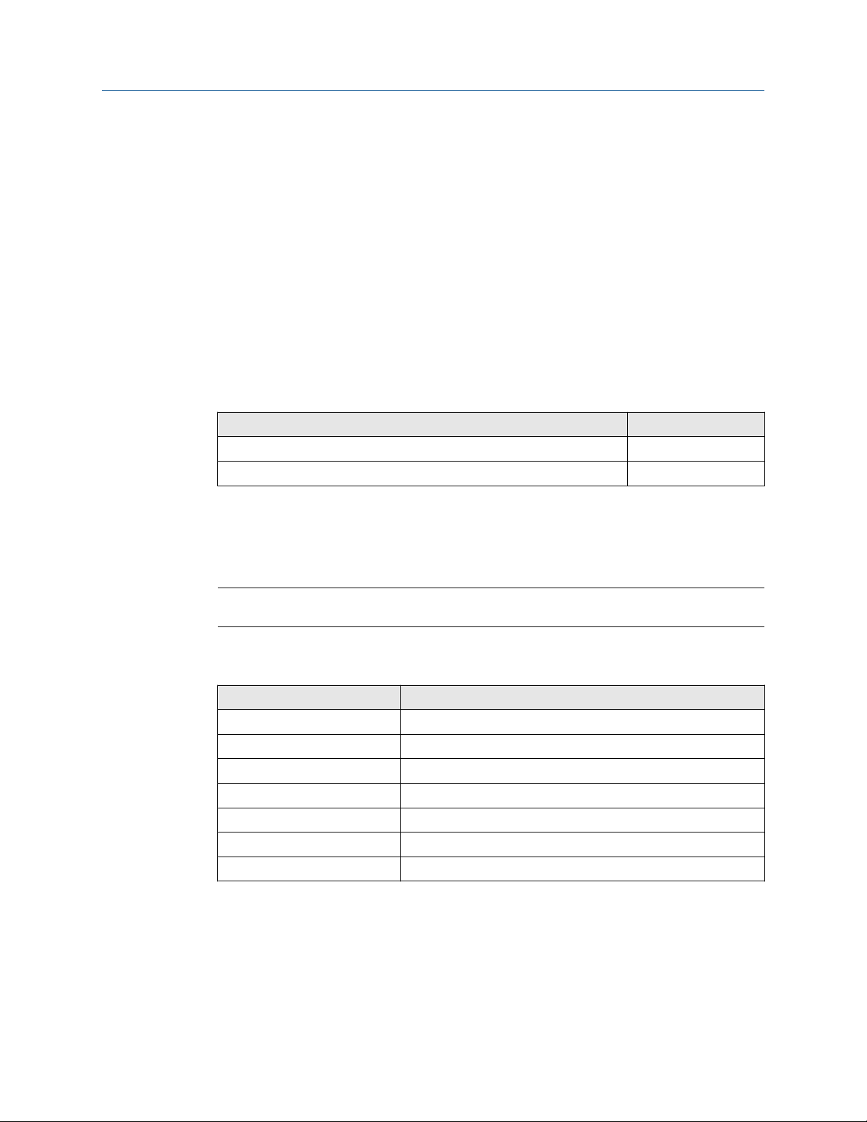
This installation guides applies for an AMS Asset Monitor with a hardware revision listed in
Table 1-1. See type plate for revision level.
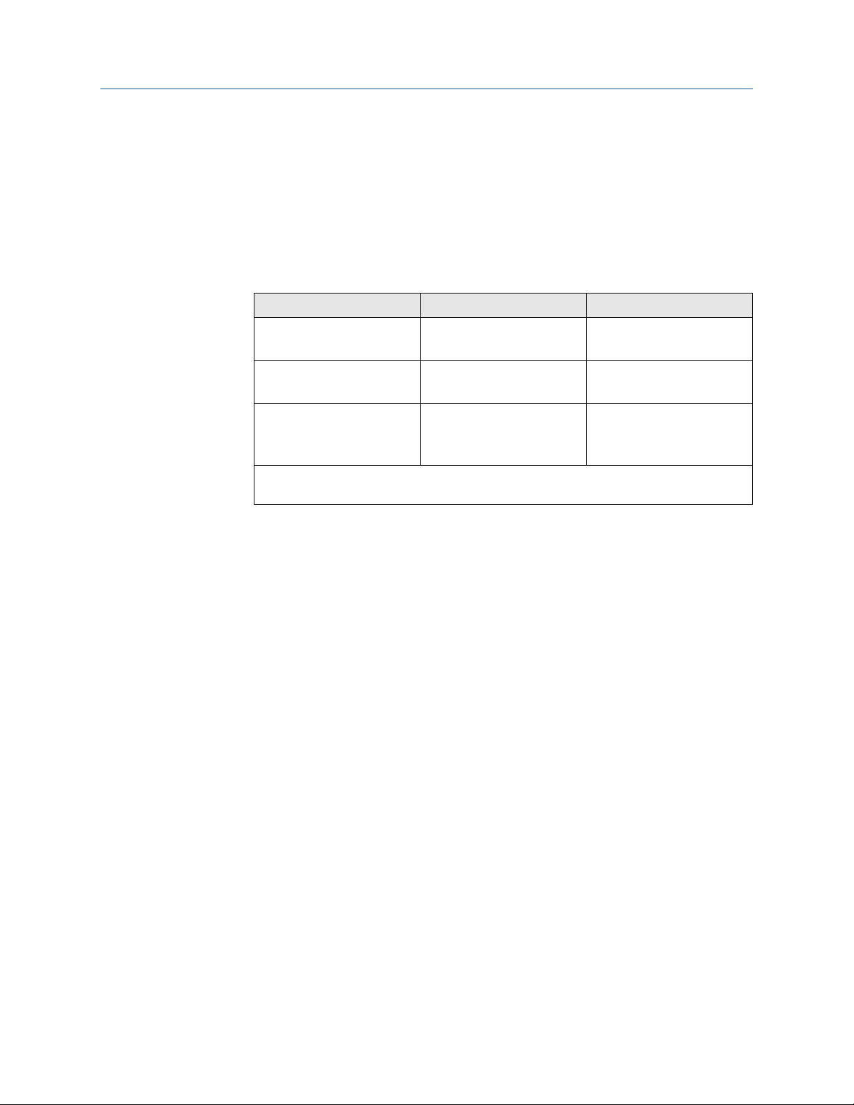
Table 1-1: Hardware revision
Component Revision
AMS Asset Monitor 13 and later
+24 V DC Power Module 08, 09
The hazardous location approvals described in Hazardous location installation and the EU
Declaration of Conformity (Certificates) do not apply to the blue AMS Asset Monitor –
Marine Paint variant AM 5820-IM BL.
Include the installation guide when transferring the device to third parties.
Note
When requesting technical support, indicate type and serial number from the type plate.
See Table 1-2 for a list of documents referred to in this installation guide.
Table 1-2: Referenced documents
Part number Document name
MHM-97924-PBF Operating Manual AMS Asset Monitor
MHM-97925-PBF Installation Guide VI Piezo CHARM
MHM-97930-PBF Installation Guide VI Tach CHARM
MHM-97929-PBF Installation Guide VI Voltage CHARM
D800040X072 DeltaV™ S-series and CHARMs Hardware Reference
12P5401 Div. 2 Installation Instruction
12P5403 Zone 2 Installation Instruction
See Table 1-3 for product type and ordering numbers of the hardware referred to in this
installation guide.
MHM-97923-PBF, Rev. 2.5 9

General Installation Guide
June 2022 MHM-97923-PBF
Table 1-3: Product type and ordering numbers of AMS Asset Monitor and compatible
DeltaV hardware
Hardware Product type number Ordering number
AMS Asset Monitor AM 5820-IM SE8701T01-IM
AMS Asset Monitor – Marine
Paint
+24 V DC Power Module AM 5730 SE8701T02-IP
VI Piezo CHARM AM 5125 SE8701V01-PZ
VI Voltage CHARM AM 5620 SE8701V02-VT
VI Tach CHARM AM 5312 SE8701V03-TH
RTD CHARM KL3031X1-BA1 SE4303T03
Thermocouple/mV input
CHARM
AI 4 to 20 mA CHARM KL3021X1-BA1 SE4303T01
DI 24 V DC Low-Side Sens (dry
contact) CHARM
DO 24 V DC High-Side CHARM KL3002X1-BA1 SE4302T01
Standard Terminal Block KL4502X1-BA1 SE4501
Thermocouple/mV Terminal
Block
Relay Output Terminal Block KL4502X1-MA1 SE4503
Address Terminal Screw Block KL4502X1-DA1 KL4502X1-DA1
Address Terminal Plug #1 KL4501X1-BA1 KL4501X1-BA1
AM 5820-IM BL SE8701T01-IM2
KL3032X1-BA1 SE4303T02
KL3003X1-BA1 SE4301T02
KL4502X1-NA1 SE4504
Channel Identifier Label\Wiring
Cover
--- SE4606T04
1.2 Symbols
Note
This symbol marks passages that contain important information.
CAUTION
This symbol marks operations that can lead to malfunctions or faulty measurements, but
will not damage the device.
DANGER
A danger indicates actions that can lead to property damage or personal injury.
According to IEC 61010, this symbol means that this device must be
operated with DC voltage.
10 MHM-97923-PBF, Rev. 2.5

Installation Guide General
MHM-97923-PBF June 2022
Warning, electric shock hazard.
According to IEC 61010, this symbol means that the documentation of
the device must completely be read and understood before installing and
commissioning of the device. Observe all safety related instructions in this
document.
1.3 Liability and guarantee
Emerson is not liable for damages that occur due to improper use. Proper use also includes
the knowledge of, and compliance with, this document.
Customer changes to the device that have not been expressly approved by Emerson will
result in the loss of guarantee.
Due to continuous research and further development, Emerson reserves the right to
change technical specifications without notice.
1.4 Incoming goods inspection
Check the content of the shipment to ensure that it is complete. Inspect the goods to
determine if the device has been damaged during transport. The following parts are at
least included in the scope of delivery and must be contained in the shipment:
• AMS Asset Monitor
• Quick Start Guide AMS Asset Monitor (MHM-97926-PBF)
If the contents are incomplete, or if you observe any defects, file a complaint with the
carrier immediately. Inform the responsible Emerson sales organization, so your device
can be replaced. In this case, attach a tag with customer name and the observed defect.
Additional parts are required to set up an operable system, see About the AMS Asset
Monitor hardware for details.
1.5 Technical support
You may need to ship this product for return, replacement, or repair to an Emerson
Product Service Center. Before shipping this product, contact Emerson Product Support to
obtain a Return Materials Authorization (RMA) number and receive additional instructions.
Product Support
Emerson provides a variety of ways to reach your Product Support team to get the answers
you need when you need them:
Phone
MHM-97923-PBF, Rev. 2.5 11
Toll free 800.833.8314 (U.S. and Canada)
+1.512.832.3774 (Latin America)

General Installation Guide
June 2022 MHM-97923-PBF
+63.2702.1111 (Asia Pacific, Europe, and Middle East)
Email
Web
To search for documentation, visit http://www.emerson.com.
To view toll free numbers for specific countries, visit http://www.emersonprocess.com/
technicalsupport.
Note
If the equipment has been exposed to a hazardous substance, a Material Safety Data Sheet
(MSDS) must be included with the returned materials. An MSDS is required by law to be
available to people exposed to specific hazardous substances.
Guardian.GSC@Emerson.com
http://www.emerson.com/en-us/contact-us
1.6 Storage and transport
Store and transport the device only in its original packaging. Technical data specifies the
environmental conditions for storage and support.
1.7 Disposal of the device
Provided that no repurchase or disposal agreement exists, recycle the following
components at appropriate facilities:
• Recyclable metal
• Plastic elements
Sort the remaining components for disposal, based on their condition. National laws or
provisions on waste disposal and protection of the environment apply.
Note
Environmental hazards! Electrical waste and electronic components are subject to
treatment as special waste and may only be disposed by approved specialized companies.
1.8 China RoHS Compliance
Our products manufactured later than June 30, 2016 and those which are sold in the
People's Republic of China are marked with one of the following two logos to indicate the
Environmental Friendly Use Period in which it can be used safely under normal operating
conditions.
Products without below mentioned marking are either manufactured before June 30 or
are non-electrical equipment products (EEP).
Circling arrow symbol with "e": The product contains no hazardous substances over
the Maximum Concentration Value and it has an indefinite Environmental Friendly
Use Period.
12 MHM-97923-PBF, Rev. 2.5

Installation Guide General
MHM-97923-PBF June 2022
Circling arrow symbol with a number: This product contains certain hazardous
substances over the Maximum Concentration Value and it can be used safely under
normal operating conditions for the number of years indicated in the symbol. The
names and contents of hazardous substances can be found in the folder "China
RoHS Compliance Certificates" on the documentation CD or DVD enclosed with the
product.
1.9 CCC Certification – AMS Asset Monitor
With the announcement of the Chinese market regulation authority SAMR (State
Administration for Market Regulation), a Compulsory Product Certification (CCC
certification) is mandatory for many explosion protection products. This explosion proof
(“Ex”) product complies to the CCC obligation and is certified (certification number:
2020322309002379).
This China Compulsory Certificate mark (CCC), is a compulsory safety mark for
many products imported, sold, or used in the Chinese market and indicates that the
product is certified in accordance to GB 3836.1-2010, GB 3836.4-2010, and GB
3836.8-2014. If the product label is to small to contain the CCC certification mark it
is sufficient to have the mark printed on the minimum package and in the attached
document.
1.10 Installation awareness
Note
When planning a measurement, observe the following items:
• Consider environmental conditions which might have an influence on the
measurement such as temperature, humidity, substances aggressive to the sensor,
and pollution.
• Always use a stiff and vibration-free sensor holder.
• Define a suitable measuring range, not larger than necessary, in consultation with the
operator of the plant.
• Define the trip limit in consultation with the operator of the plant.
• Take measurement deviations into account when defining the trip limit.
• Use a sensor that meets the requirements of the defined measuring range.
• Ensure an EMC-compatible installation including the use of proper cables.
• Ensure proper function of the measurement before activating the measurement for
regular operation.
MHM-97923-PBF, Rev. 2.5 13

General Installation Guide
June 2022 MHM-97923-PBF
14 MHM-97923-PBF, Rev. 2.5

Installation Guide Safety instructions
MHM-97923-PBF June 2022
2 Safety instructions
To ensure safe operation, carefully observe all instructions in this manual.
The correct and safe use of this device requires that operating and service personnel both
understand and comply with general safety guidelines and observe the special safety
comments listed in this manual. Where necessary, safety-sensitive points on the device
are marked.
DANGER
Because the device is electrical equipment, commissioning and service must be performed
only by trained and authorized personnel. Maintenance must be carried out only by
trained, specialized, and experienced personnel.
2.1 Using the device
Install and use the device as specified in this document.
If the device is used in a manner not specified by the manufacturer, the functions and
protection provided by the device may be impaired.
2.2 Owner's responsibility
If there is a reason to suspect that hazard-free operation, and thus, adequate machine
protection is no longer possible, take the device out of operation and safeguard it from
unintentional operation. This is the case:
• if the device shows visible damage.
• if the device no longer works.
• after any kind of overload that has exceeded the permissible limits (such as those
detailed in chapter "Technical data," section "Environmental conditions").
DANGER
If device tests have to be completed during operation or if the device has to be replaced or
decommissioned, it will impair the machine protection and may cause the machine to
shut down. Make sure to deactivate machine protection before starting such work, and
reactivate it after work has been completed.
2.3 Radio interference
The device is carefully shielded and tested to be technically immune to radio interference
and complies with current standards. However, if you operate this device together with
other peripheral devices that are not properly shielded against radio interference,
disturbances and radio interferences may occur.
MHM-97923-PBF, Rev. 2.5 15

Safety instructions Installation Guide
June 2022 MHM-97923-PBF
2.4 ESD safety
DANGER
Internal components can be damaged or destroyed due to electrostatic discharge (ESD)
during the handling of the device.
Take suitable precautions before handling the device to prevent electrostatic discharges
through the sensor electronics. Such measures might include, for example, wearing an
ESD bracelet. Transport and storage of electronic components may only be made in ESDsafe packaging.
Handle the device with particular care during dry meteorological conditions with relative
humidity below 30% as electrostatic discharges can appear more frequently.
2.5 Important information about hazardous live voltages
DANGER
The KL4502X1-MA1 CHARM Relay Output Terminal Block may have hazardous live
voltages on its output terminals. This terminal block is capable to switch field power of 250
V AC. Ensure that proper safety precautions, such as de-energizing field power, are
observed during installation, maintenance, or any time wiring changes are made to the
CHARM Relay Output Terminal Block.
For further information about hazardous live voltages see Wiring guidelines and CSA –
General safety.
16 MHM-97923-PBF, Rev. 2.5

Installation Guide Planning the installation
MHM-97923-PBF June 2022
3 Planning the installation
Emerson recommends two people to mount the AMS Asset Monitor.
3.1 Tools required to install the hardware
Standard tools are required to install the AMS Asset Monitor hardware:
Wire cutter
Wire stripper
Crimper
3.5 mm flat-tip
screwdriver
PH 2 cross-tip
screwdriver
PZ 3 cross-tip
screwdriver
Screwdriver
Voltmeter
For shortening the connection wires.
For removing the insulation from the wire.
For crimping ferrules.
For the CHARM Terminal Block, power supply terminals, and
baseplate grounding terminals.
For the internal grounding terminals of the AMS Asset
Monitor.
For the door screws and grounding terminal at the AMS Asset
Monitor bottom.
Suitable for the screws, selected for mounting the AMS Asset
Monitor on a wall, mounting plate, or mounting frame. Size
and type of the screwdriver depends on the selected fixing
method.
To check the supply voltage and the connected signals.
3.2 Torque limits for mounting screws
Table 3-1 lists the permissible maximum torque limits for the screws of the AMS Asset
Monitor hardware.
Table 3-1: Maximum torque limits
Hardware part Maximum torque limit
Power supply terminal screws 0.5 Nm
CHARM Terminal Block screws 0.45 Nm
Cable shield grounding terminals 0.45 Nm
Grounding terminal at the bottom 8.7 Nm
Additional grounding terminals for ground connection 5.1 Nm
The recommended tightening torque is the maximum torque limit minus 20%.
MHM-97923-PBF, Rev. 2.5 17

Planning the installation Installation Guide
June 2022 MHM-97923-PBF
3.3 Wiring guidelines
This section contains general information and wiring hints. As always, proper cable
installation depends on observation and judgment based on the situation on-site. Observe
the following points for a reliable cable installation:
• Install cables according to general standards for measuring and control cables.
• Separate AC voltage circuits from low voltage signals to comply with safety
recommendations and to mitigate induced noise in the signals. This good practice is
recommended by Emerson although any signal type can be installed in any CHARM slot
of the AMS Asset Monitor.
• If possible, install cables in metallic cable channels or tubes.
• Observe an orthogonal cable routing.
• Do not squeeze, bent, or twist cables. Always observe the permissible bending radius
of the used cable.
• Install cables strain-free and spin-free to protect them against mechanical damages.
• Affix cables to a secure surface at regular, short distances.
• Ensure that no parts of the cable touch any rotating parts of the machine.
• Note that machine parts or other metallic parts can expand or shrink due to
temperature influences. Always install cables with a cable length reserve to
compensate the thermal behavior of such parts.
•
Always use ferrules for stranded wires. Ensure that all strands are covered by the
ferrule so that no strand can contact an adjacent terminal. When strands are
stripped 10 mm and ferrules are not used, consider that there is a risk of short
circuit – a possibility of accidental contact between HAZARDOUS LIVE parts of
different polarity.
• At environmental temperatures of 50°C and above use cables suitable for temperatures
above 60°C within the AMS Asset Monitor.
See Table 3-2 for the permissible wire-cross sections for the voltage supply terminals and
cable shield terminals. For the maximum tightening torque see Torque limits for mounting
screws.
Table 3-2: Permissible wire-cross sections
Wire description Wire cross-section
Minimum Maximum
Power supply terminals Conductor cross section
stranded
Conductor cross section
stranded AWG
Cable shield terminals Conductor cross section 0.32 mm
0.2 mm
24 12
2
2
2.5 mm
2.5 mm
2
2
Conductor cross section
AWG
18 MHM-97923-PBF, Rev. 2.5
22 14

Installation Guide Planning the installation
MHM-97923-PBF June 2022
Table 3-2: Permissible wire-cross sections
Wire description Wire cross-section
CHARM Terminal Blocks Conductor cross section
The recommended stripping length of the wires is 10 mm.
3.3.1 Wiring overview
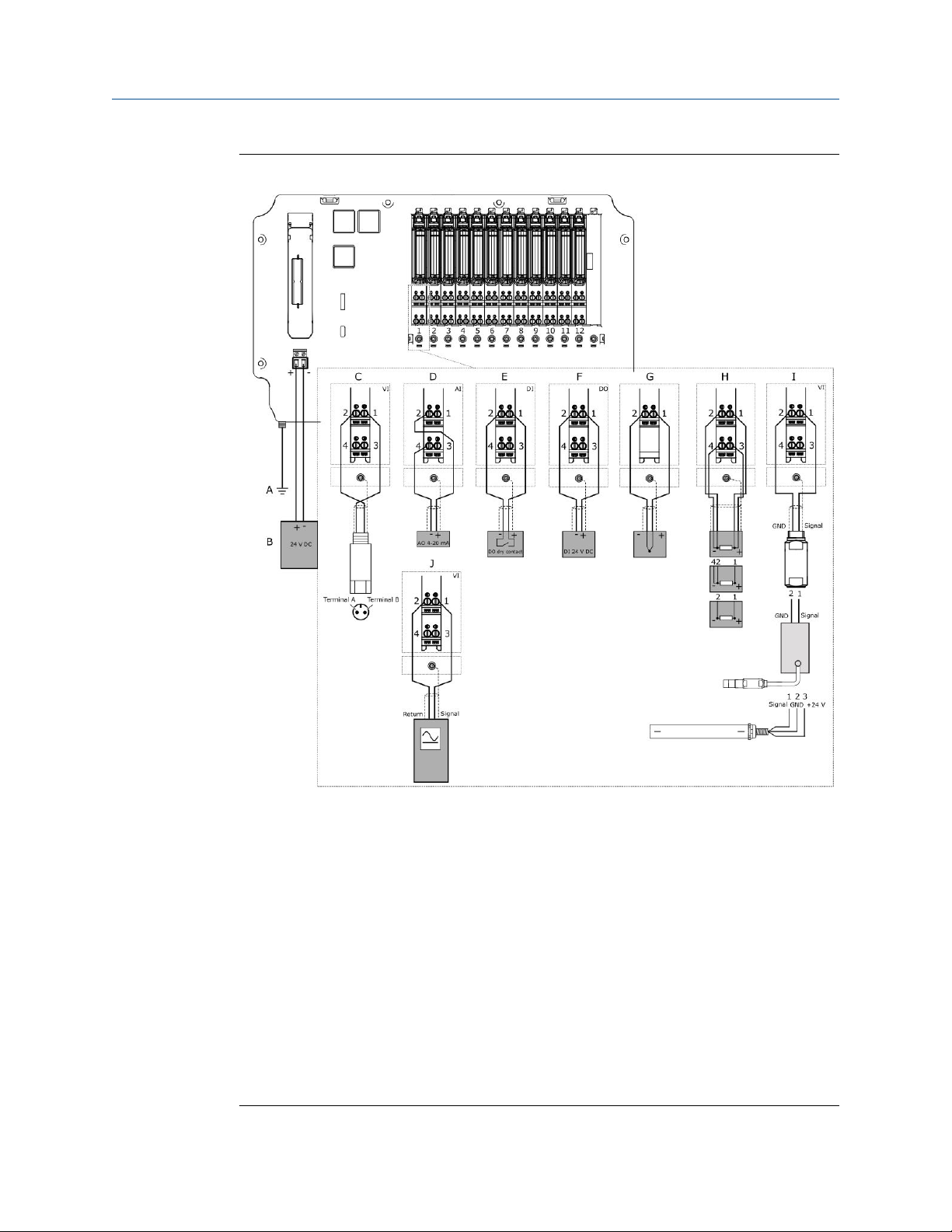
See Figure 3-1 for an example overview of a standard wiring of an AMS Asset Monitor.
(continued)
Minimum Maximum
22 14
AWG (stranded or solid)
MHM-97923-PBF, Rev. 2.5 19
Planning the installation Installation Guide
June 2022 MHM-97923-PBF
Figure 3-1: Wiring overview
A. Connection to protective ground, see Grounding
B. 24 V DC power supply for the AMS Asset Monitor, see Connect the power supply
C. Connection VI Piezo CHARM, see Connect the sensor wiring
D. Connection analog input AI 4-20 mA CHARM, see Connect the input signal wiring – self-
powered and Connect the input signal wiring – loop-powered
E. Connection digital input DI 24 V DC low-side sense CHARM, see Connect the input signal
wiring
F. Connection digital output DO 24 V DC high-side CHARM, see Connect the output signal
wiring and Connect the relay output wiring
G. Connection Thermocouple Input CHARM, see Connect the sensor wiring
H. Connection RTD Input CHARM (4-wire RTD, 3-wire RTD, and 2-wire RTD), see Connect
the sensor wiring
I. Connection VI Tach CHARM (magnetic pickup, eddy current signal, and Hall-effect
sensor), see Connect the sensor wiring
J. Connection VI Voltage CHARM, see Connect the voltage input wiring
20 MHM-97923-PBF, Rev. 2.5

Installation Guide Planning the installation
MHM-97923-PBF June 2022
3.4 Select a mounting place
Select a suitable mounting place for the AMS Asset Monitor. Requirements for the
mounting place:
• A flat surface like a wall, mounting plate, or a framework. Ensure that the surface of the
selected mounting place does not impair the airflow at the rear side of the AMS Asset
Monitor.
• A location close to the machine to be monitored. The maximum distance between the
AMS Asset Monitor and the machine depends on the maximum permissible signal
cable length of the connected sensors.
• Place the AMS Asset Monitor on a higher level than sensors installed in the machine to
prevent oil from entering the AMS Asset Monitor through the cables.
• Place the AMS Asset Monitor so that all cables can be led through the cable glands at
the bottom of the AMS Asset Monitor.
• Avoid locations where the AMS Asset Monitor is commonly exposed to direct sunlight.
• A 24 V DC power supply for supplying the AMS Asset Monitor.
• An Ethernet network connection for connecting the AMS Asset Monitor to a network.
• Sufficient space in front of the AMS Asset Monitor to open the door (see Dimensions
and electrical data – AMS Asset Monitor for dimensions).
• Sufficient space around the AMS Asset Monitor to ensure proper cooling. Ensure that
there is no heated surface beneath the AMS Asset Monitor.
• Consider the environmental conditions stated in Environmental conditions – AMS
Asset Monitor.
MHM-97923-PBF, Rev. 2.5 21

Planning the installation Installation Guide
June 2022 MHM-97923-PBF
22 MHM-97923-PBF, Rev. 2.5
Installation Guide Installing AMS Asset Monitor hardware
MHM-97923-PBF June 2022
4 Installing AMS Asset Monitor
hardware
4.1 CSA – General safety
Conditions of acceptability
Observe the listed conditions to built-up a system in accordance with the CSA approval:
• A disconnecting device (required by clause 6.11 of IEC 61010-1:2010) has to be
provided, the power supply disconnecting device or interrupt facility may be used.
• The equipment is supplied by a certified power source which is approved in accordance
to IEC 60950-1 or IEC 61010-1. The DC output of this separately certified power source
shall be below the limits of clause 6.3.1 and 9.4 of IEC 61010-1:2010.
• In combination with a certified external fuse or circuit breaker that shall be used with
the device, all devices are considered to fulfill the requirements of a limited energy
source to clause 9.4 of IEC 61010-1:2010.
This condition does not apply to the Relay Output Terminal Block (KL4502X1MA1).
• Suitable external cords shall be used in the end application and shall be according to
local rules and standards.
• If at any time there is a conflict between the system safety provisions and any relevant
local (national or regional) requirements, the local requirements always take
precedence.
•
The voltage between adjacent terminal blocks must not exceed 300 V.
• The sum of the load current of the outputs of all Discrete Output CHARMs (KL3002X1-
BA1) installed in the AMS Asset Monitor must not exceed 1200 mA, each output must
not exceed 100 mA.
4.2 About the AMS Asset Monitor hardware
The AMS Asset Monitor BASE hardware consists of a rugged enclosure with internal
electronics designed to support up to 12 CHARMs1, an address module, and a +24 V DC
Power Module. The BASE unit provides the infrastructure that connects the CHARMs and
their field signal to the integrated analytics. For communication and configuration, the
AMS Asset Monitor is equipped with three Ethernet interfaces. Use two of the Ethernet
1
CHAR
acterizing Module
MHM-97923-PBF, Rev. 2.5 23

Installing AMS Asset Monitor hardware Installation Guide
June 2022 MHM-97923-PBF
interfaces to daisy chain AMS Asset Monitors. Because of the possible network traffic,
Emerson recommends to daisy chain no more than eight AMS Asset Monitors.
The following parts are at least required to set up an operable system:
• AMS Asset Monitor
• +24 V DC Power Module
• CHARMs (CHARM types in accordance to the supervision tasks)
• CHARM Terminal Blocks suitable for the selected CHARMs
• Cable glands, suitable for the environmental conditions on-site
• Address plug with suitable terminal block
The AMS Asset Monitor supports the VI Piezo CHARM, the VI Voltage CHARM, the VI Tach
CHARM, and the DeltaV hardware listed in Table 4-1.
Table 4-1: Supported DeltaV devices
Hardware Type
number
RTD CHARM KL3031X1-
BA1
Thermocouple/mV input CHARM KL3032X1-
BA1
AI 4 to 20 mA CHARM
DI 24 V DC Low-Side Sens (dry
contact) CHARM
DO 24 V DC High-Side CHARM KL3002X1-
Standard Terminal Block KL4502X1-
Thermocouple/mV Terminal Block KL4502X1-
Relay Output Terminal Block KL4502X1-
Address Terminal Screw Block KL4502X1-
Address Terminal Plug #1 KL4501X1-
1
KL3021X1BA1
KL3003X1BA1
BA1
BA1
NA1
MA1
DA1
BA1
Description
CHARM for temperature measurement with
RTD sensors
CHARM for temperature measurement with
Thermocouples
Analog input CHARM for 4 to 20 mA signals
Discrete input CHARM for sensing relay/switch
contact closure
Discrete output CHARM for momentary output
signals or continuous pulse outputs
Terminal block for connection most of the
CHARMs
Terminal block for thermocouple sensors or
mV signals
Output terminal block with relay contacts
Screw terminal block for address plug
Address plug
CHARM Protection Cover KL4502X1-
QA1
Channel Identifier Label/Wiring
Cover
1
No HART (Highway Addressable Remote Transducer) support.
24 MHM-97923-PBF, Rev. 2.5
SE4606T04 Horizontal channel identifier label
Protection cover that fits all terminal blocks

Installation Guide Installing AMS Asset Monitor hardware
MHM-97923-PBF June 2022
The electrical rating of all devices listed in Table 4-1, except the Relay Output Terminal
Block (KL4502X1-MA1), is maximal 100 mA at 24 V DC. The electrical rating of the Relay
Output Terminal Block is maximal 5 A at 250 V, overvoltage category 2.
Ensure that an AMS Asset Monitor used in high voltage applications, high voltages on the
mainboard with rated values up to 250 V AC, 100 mA, and 25 VA, is fully equipped with
terminal blocks. Use a transformer to separate primary circuits (high voltage circuits) from
secondary circuits by double insulation, reinforced insulation or a separator, which is
connected to protection earth.
The maximum permissible input voltage of the VI Tach CHARM is 30.3 V AC. The
maximum input voltage of 30.3 V AC is also the maximum permissible input voltage when
using the VI Tach CHARM in explosion-hazardous areas.
The AMS Asset Monitor has cable entries with 1/2-NPT cable gland threading.
Note
The AMS Asset Monitor is shipped with dust protective caps in the cable inlets. These red
colored caps are only to protect the inner parts of the AMS Asset Monitor during transport.
Remove the dust caps and replace them with proper cable glands or screw plugs. See
Replace the cable inlet dust caps.
See Figure 4-1 to Figure 4-3 for hardware details.
MHM-97923-PBF, Rev. 2.5 25

Installing AMS Asset Monitor hardware Installation Guide
June 2022 MHM-97923-PBF
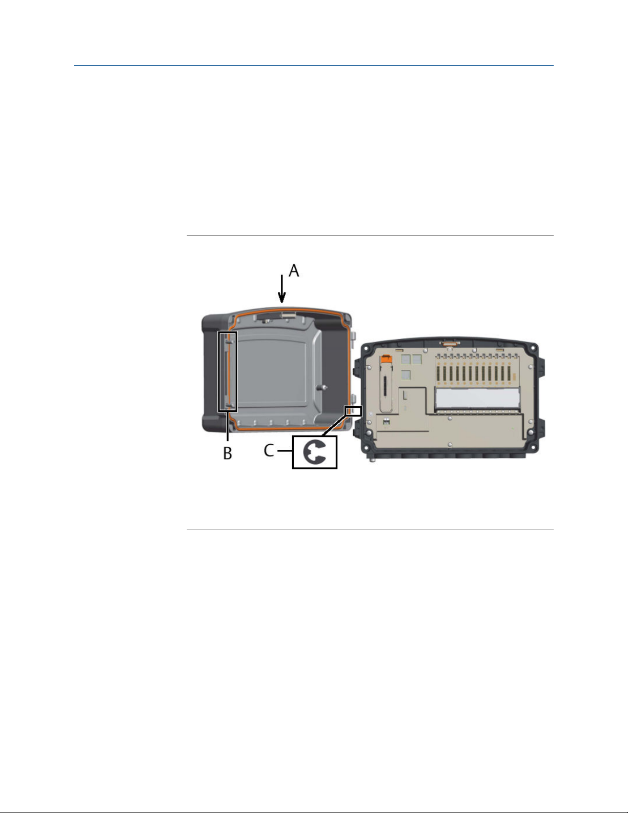
Figure 4-1: Overview – AMS Asset Monitor
A. Status light (if several notifications are present, always the worst is indicated)
B. Door
C. Screws for securing the door
D. Base
E. External grounding terminal
F. Cable entries (cable glands are an optional accessory)
26 MHM-97923-PBF, Rev. 2.5

Installation Guide Installing AMS Asset Monitor hardware
MHM-97923-PBF June 2022
Figure 4-2: Overview – rear side AMS Asset Monitor
A. Mounting holes
B. Pressure compensation vent
C. Blind mounting holes with standard M8x1.25 thread
MHM-97923-PBF, Rev. 2.5 27

Installing AMS Asset Monitor hardware Installation Guide
June 2022 MHM-97923-PBF
Figure 4-3: Overview – open AMS Asset Monitor
A. Ethernet switch with two RJ-45 connectors (left connector: LAN2.1, right connector
LAN2.2) to daisy chain AMS Asset Monitors2, speed 100 Mbit/s
B. RJ-45 Ethernet connector LAN1 for configuration and connection to subsequent systems,
speed 1 Gbit/s
C. Status light
D. CHARM baseplate with 12 slots for up to 12 CHARM terminal blocks, 12 CHARMS, and a
CHARM labeling component
E. Mounting holes
F. Door hinge
G. Screws holes for securing the door
H. Power module slot
I. Address plug slot
J. External grounding terminal
K. Power supply terminals
L. Covered. Non-functional. For internal use only.
M. microSD Card slot (for future use)
N. Reset button with status LED
O. Internal grounding terminals
+24 V DC Power Module
The +24 V DC Power Module is used to supply the AMS Asset Monitor including all installed
CHARMs.
2
Because of the possible network traffic, Emerson recommends to daisy chain no more than eight AMS Asset Monitors.
28 MHM-97923-PBF, Rev. 2.5

Installation Guide Installing AMS Asset Monitor hardware
MHM-97923-PBF June 2022
Figure 4-4: +24 V DC Power Module
A. Green and red LED for status indication, see Table 4-2
Table 4-2: Meaning of the LED indication
Event LED indication
LED Blinking pattern
Power Module active Green Solid
Power Module inactive Green Off
Input voltage is below 21.6 V DC Red Solid
Input voltage is above 26.4 V DC Red Solid
Input voltage is between 21.6 V DC and 26.4 V DC Red Off
4.3 Position of the mounting holes
The AMS Asset Monitor has four through holes without thread and four blind holes with a
standard M8 thread to mount the AMS Asset Monitor on a flat surface like a wall or on a
framework.
MHM-97923-PBF, Rev. 2.5 29

Installing AMS Asset Monitor hardware Installation Guide
June 2022 MHM-97923-PBF
Figure 4-5: Position of the four through holes for mounting
A. 196 mm
B. 6.5 mm
C. 330 mm
30 MHM-97923-PBF, Rev. 2.5

Installation Guide Installing AMS Asset Monitor hardware
MHM-97923-PBF June 2022
Figure 4-6: Position of the four blind holes for mounting
A. 298 mm
B. 164 mm
C. Blind hole with M8x1.25 thread; depth: 20 mm, threaded depth: 16 mm
4.4 Open the AMS Asset Monitor
All work at the AMS Asset Monitor requires an open door. If the door hinders you from
working at the AMS Asset Monitor, it can be completely removed.
Prerequisites
• A PZ 3 cross-tip screwdriver for the door screws.
• A pair of pliers or a flat-tip screwdriver to remove the circlip.
Procedure
1. Unfasten the screws which are securing the door.
MHM-97923-PBF, Rev. 2.5 31

Installing AMS Asset Monitor hardware Installation Guide
June 2022 MHM-97923-PBF
Figure 4-7: Position of the screws
A. Screws for securing the door.
2. Swivel the door to the left to open the AMS Asset Monitor.
3. To remove the door completely, remove the circlip that secures the door from
unintentional removal.
4. Unhinge the door to remove it from the AMS Asset Monitor.
Figure 4-8: Remove the door
A. Lifting direction
B. Circlip
32 MHM-97923-PBF, Rev. 2.5
Installation Guide Installing AMS Asset Monitor hardware
MHM-97923-PBF June 2022
4.5 Close the AMS Asset Monitor
Prerequisites
• A PZ 3 cross-tip screwdriver for the door screws.
Procedure
1. If the door has been removed completely, hang the door on its hinges.
2. Secure the lower hinge with the circlip.
Figure 4-9: Reattach the door
A. Mounting direction
B. Screws for securing the door
C. Circlip
3. Close the door and secure it by fastening the screws.
Tighten the screws until the door touches the base, and is squeezed to ensure a
proper seal.
4.6 Recommended sequence for installing the AMS Asset Monitor
The described installation sequence is a recommendation and can be changed to the
needs of your project.
Procedure
1. Remove the door of the AMS Asset Monitor.
2. Mount the AMS Asset Monitor.
MHM-97923-PBF, Rev. 2.5 33

Installing AMS Asset Monitor hardware Installation Guide
June 2022 MHM-97923-PBF
3. Mount cable glands or sealing blind plugs.
4. Install the +24 V DC Power Module.
5. Install the desired CHARMs with terminal blocks.
6. Install the address block.
7. Connect the field wiring.
8. Connect the Ethernet network.
If more than one AMS Asset Monitors are installed, Emerson recommends to daisy
chain them.
9. Connect the power supply and the grounding.
10. Check the installation by checking all cable connections, the power supply voltage,
the LEDs on the devices, and testing the field wiring.
11. Reattach the door.
4.7 Mount the AMS Asset Monitor
Prerequisites
You need two people to lift the AMS Asset Monitor and fix it on the mounting place.
Procedure
1. Remove the door of the AMS Asset Monitor. See Open the AMS Asset Monitor.
2. Prepare the mounting place. Check if available holes fit to the hole pattern of the
AMS Asset Monitor. If not, drill suitable holes according to the hole pattern. See
Position of the mounting holes.
The required diameter and depth of the holes depend on the selected fixing
method.
3. Lift the AMS Asset Monitor on the mounting place.
Ensure that the cable entries point downwards.
4. Fix the AMS Asset Monitor with screws.
The tightening torque depends on the selected screws.
5. Reattach the door. See Close the AMS Asset Monitor.
4.8 Mount the AMS Asset Monitor by using the universal mounting bracket
Use the universal mounting bracket SE8701UMB if the AMS Asset Monitor must be
mounted at a post. The bracket is compatible with square profile posts or round profile
posts with the following dimensions:
• Round profile: outside diameter from 50 mm (2.0 in) to 88 mm (3.5 in).
• Square profile: maximum side length 88 mm (3.5 in). Reverse the clamping jaws.
• When installing a new post, Emerson recommends a post with a wall thickness of 3.2
mm (1/8 in).
34 MHM-97923-PBF, Rev. 2.5
Installation Guide Installing AMS Asset Monitor hardware
MHM-97923-PBF June 2022
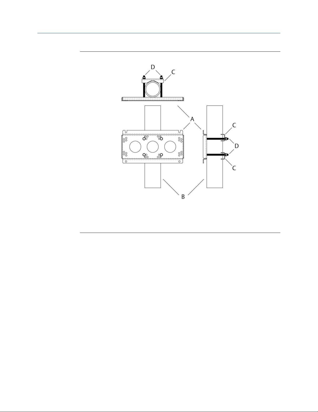
Figure 4-10: Universal mounting bracket
A. Plate
B. Post
C. Clamping jaws
D. Bolts with nuts
MHM-97923-PBF, Rev. 2.5 35
Installing AMS Asset Monitor hardware Installation Guide
June 2022 MHM-97923-PBF
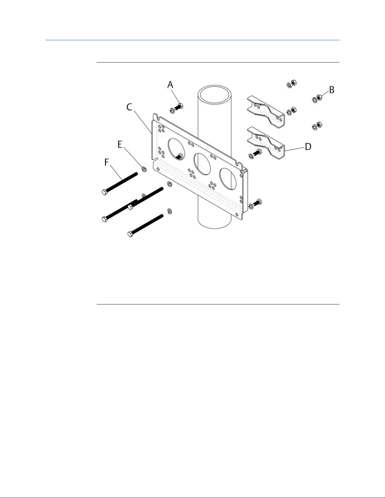
Figure 4-11: Universal mounting bracket – vertical mounting
A. M8 x 1.25 x 18 mm hex head bolt (4x) for mounting the plate on the back of the AMS
Asset Monitor
B. M8 x 1.25 hex nut (4x) for fastening the clamping jaws
C. Mounting plate
D. Clamping jaw (2x)
E. M8 split lock washer (12x)
F. M8 x 1.25 x 120 mm hex head bolt for fastening the clamping jaws
36 MHM-97923-PBF, Rev. 2.5
Installation Guide Installing AMS Asset Monitor hardware
MHM-97923-PBF June 2022
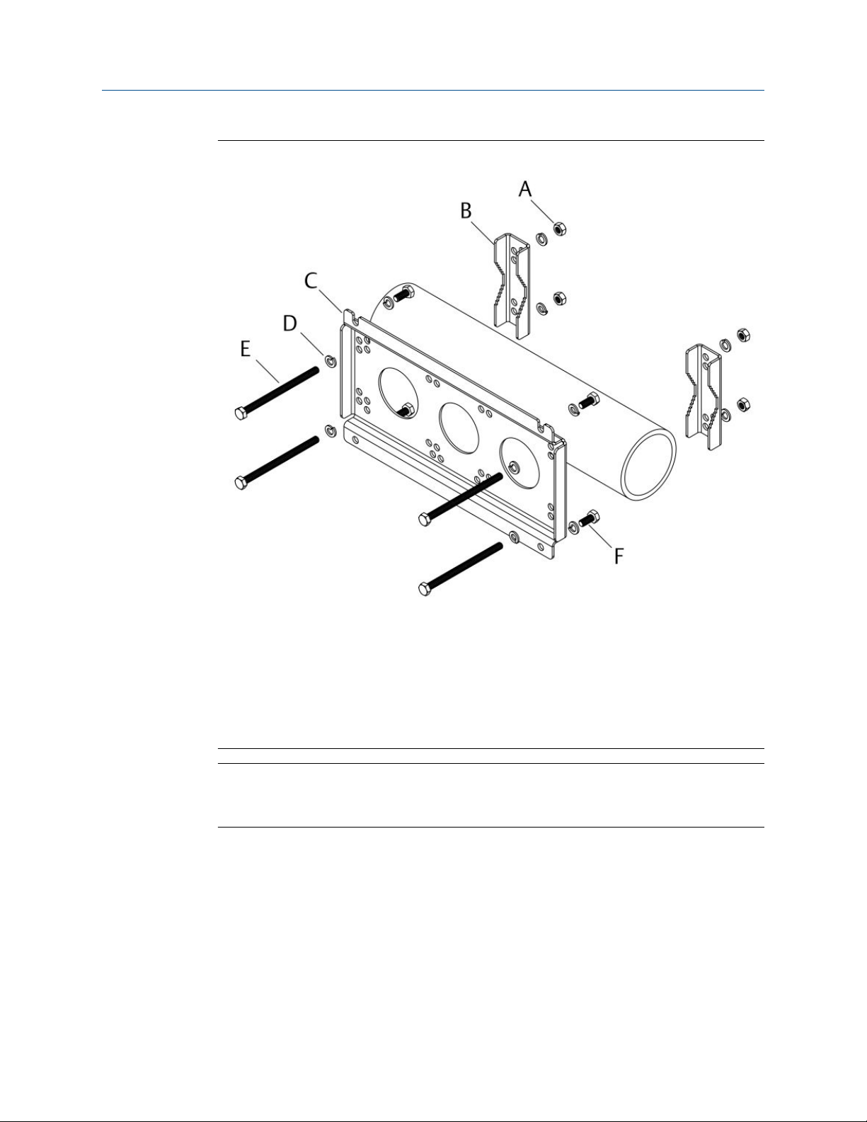
Figure 4-12: Universal mounting bracket – horizontal mounting
A. M8 x 1.25 hex nut (4x) for fastening the clamping jaws
B. Clamping jaw (2x)
C. Mounting plate
D. M8 split lock washer (12x)
E. M8 x 1.25 x 120 mm hex head bolt for fastening the clamping jaws
F. M8 x 1.25 x 18 mm hex head bolt (4x) for mounting the plate on the back of the AMS
Asset Monitor
Note
Ensure that the post can permanently bear the weight of the AMS Asset Monitor.
Do not mount the AMS Asset Monitor on piping in use.
Prerequisites
You need two suitable spanners/wrenches with 13 mm opening. The tightening torque
may vary depending on the on-site situation.
Procedure
1. Insert the M8 x 1.25 x 120 mm hex head bolts including the split lock washers in the
mounting plate.
• For mounting on a vertical post, use the holes in the middle of the bracket (see
Figure 4-11).
MHM-97923-PBF, Rev. 2.5 37
Installing AMS Asset Monitor hardware Installation Guide
June 2022 MHM-97923-PBF
• For mounting on a horizontal post, use the outer holes of the bracket (see Figure
4-12).
2. Place the bracket according to the selected mounting orientation (vertical or
horizontal) on the post. The recesses for the M8 x 1.25 x 18 mm hex head bolts for
mounting the plate on the back of the AMS Asset Monitor must point upwards.
3. Put the clamping jaws on the 120 mm bolts. Align them with the profile of the pole
and fasten the jaws with the included M8 nuts.
4. Check for a tight fit of the mounting bracket.
After proper fastening of the nuts, the mounting bracket cannot be turned at the
post or slipped down.
5. Screw two of the four M8 x 1.25 x 18 mm hex head bolts into both upper blind
mounting holes of the AMS Asset Monitor (see About the AMS Asset Monitor
hardware for location of the blind holes) so that the bolts protrude approximately 8
mm from the Monitor's surface.
6. Hang the AMS Asset Monitor with the bolts mounted beforehand in the recesses of
the bracket.
Ensure that the cable entries point downwards.
7. Screw in the remaining M8 x 1.25 x 18 mm hex head bolts into the lower blind
mounting holes.
8. Tighten the bolts to fix the AMS Asset Monitor on the mounting bracket.
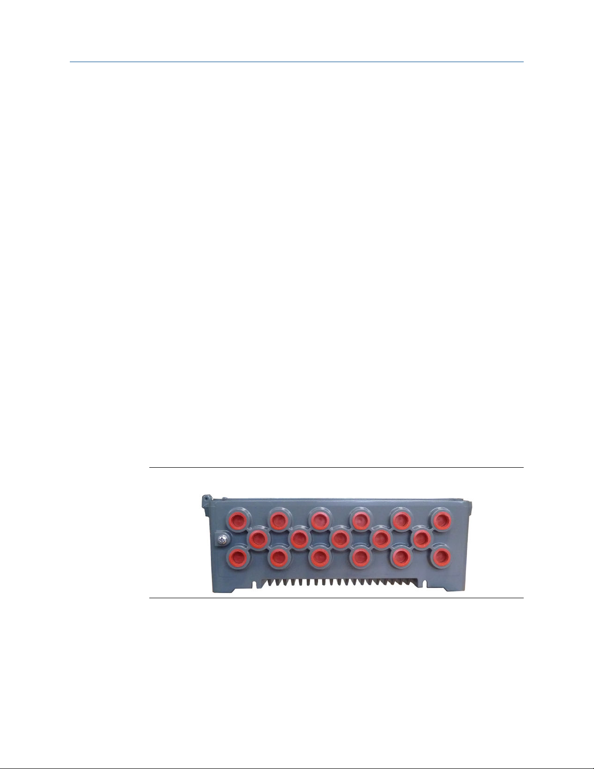
4.9 Replace the cable inlet dust caps
The AMS Asset Monitor is shipped with dust protective caps in the cable inlets. These red
colored caps are only to protect the inner parts of the AMS Asset Monitor during transport.
Remove the dust caps and replace them by proper cable glands or screw plugs to achieve
the specified protection class of the AMS Asset Monitor.
Figure 4-13: Dust protective caps – bottom view
Prerequisites
Select cable glands and screw plugs suitable for the application. Observe the following
points when selecting cable glands and screw plugs:
• Ensure that the cable glands are suitable for the diameter of the used cables.
• All not used cable inlets must be closed by using screw plugs.
38 MHM-97923-PBF, Rev. 2.5

Installation Guide Installing AMS Asset Monitor hardware
MHM-97923-PBF June 2022
• The AMS Asset Monitor is available with cable inlets with NPT thread.
• For hazardous location installation, use cable glands and screw plugs with an
appropriate approval.
Procedure
1. Remove all red dust caps.
Press the caps out from the inside or use a pair of pliers to pull them out.
2. Screw the required cable glands into the cable inlets.
Ensure proper sealing of the cable glands to keep the IP protection of the AMS Asset
Monitor. See documentation of the used cable glands for details.
3. Close the remaining cable inlets with screw plugs.
Ensure proper sealing of the cable inlets to keep the IP protection of the AMS Asset
Monitor. See documentation of the used screw plugs for details.
4. Continue with wiring and cable installation.
4.10 Grounding
Note
The grounding connections, described in this section, are examples. Adapt these examples
to the installation situation on-site. Observe local regulations regarding grounding and
installation of electrical equipment. The transition resistance between housing and
protective ground must be <100 mΩ measured at 40 A. The connection cable must be
colored green or green/yellow.
The AMS Asset Monitor has a grounding terminal at the bottom. The grounding terminals
for the shields of the field wiring cables and the two additional internal grounding
terminals in the lower left and right corner are internally connected to this grounding
terminal.
A ground connection between the housing of the AMS Asset Monitor and protective
ground is at least required if field signals with up to 250 V AC are connected. The
KL4502X1-MA1 CHARM Relay Output Terminal Block may have hazardous live voltages on
its output terminals. This terminal block is capable to switch field power of up to 250 V AC.
The minimum required grounding connection is a connection between the labeled
internal grounding terminal and protective ground.
MHM-97923-PBF, Rev. 2.5 39

Installing AMS Asset Monitor hardware Installation Guide
June 2022 MHM-97923-PBF
Figure 4-14: Ground connection
A. Grounding terminals for connecting the shields of the sensor or signal field cables
B. Shield of the field cable
C. Labeled internal grounding terminal
D. Internal grounding terminal
E. Minimum required grounding connection
F. External grounding terminal
G. Field cables
H. Equipotential busbar
I. Protective ground
Prerequisites
• A cross-tip screwdriver size PZ 3 for the external grounding terminal at the device
bottom
• A flat-tip screwdriver size 3.5 mm for the shield grounding terminals
• A cross-tip screwdriver size PH 2 (if using the internal grounding terminal)
Procedure
1. Connect the grounding terminal (external or internal) with the equipotential
busbar.
40 MHM-97923-PBF, Rev. 2.5

Installation Guide Installing AMS Asset Monitor hardware
MHM-97923-PBF June 2022
• External grounding terminal (recommended): Use a grounding cable with a
wire cross section in accordance to the local rules and standards. Emerson
recommends a grounding cable with a wire cross section of 6 mm2 and a cable
lug at the end suitable for the diameter of the grounding screw.
• Internal grounding terminal (minimum requirement): Use a grounding cable
with a wire cross section equal to the wire cross section of the cable with the
hazardous live voltages and a cable lug at the end suitable for the diameter of
the grounding screw.
Ensure that the equipotential busbar is connected to protective ground.
2. Connect the shields of the field wiring cables to ground.
• Field-side grounding (recommended): Connect the shields of the field wiring
through the asset housing to ground. The grounding ensures the electrical
interferences are not conducted through the AMS Asset Monitor.
• AMS Asset Monitor-side grounding: Select this option if it is not possible to
connect the shield of the field wiring as described above. Connect the cable
shields to the internal grounding terminals (see Figure 4-14, A).
Note
Ensure that the cable shield is not double-sided connected to ground to avoid
ground loops. There may be exceptions to this recommendation.
4.11 Network connection
The AMS Asset Monitor is equipped with an 100 MBit/s Ethernet switch with two RJ-45
sockets to daisy chain AMS Asset Monitors. Because of the possible network traffic,
Emerson recommends to daisy chain no more than eight AMS Asset Monitors. Both RJ-45
sockets (right connector: LAN2.1 and left connector: LAN2.2) of the switch are equal. See
the following diagram for an example of a network architecture with a group of AMS Asset
Monitors.
MHM-97923-PBF, Rev. 2.5 41

Installing AMS Asset Monitor hardware Installation Guide
June 2022 MHM-97923-PBF
Figure 4-15: Example network architecture
A. Ethernet switch
B. Firewall
C. Plantweb Optics
D. Ethernet switch
E. AMS Asset Monitors
DMZ: De-Militarized Zone
The third RJ-45 Ethernet socket with a speed of 1 Gbit/s is for configuration and
connection to subsequent systems in Level 3 (see Figure 4-15) such as Plantweb Optics.
See Figure 4-3 for the location of the RJ-45 sockets.
Note
There is no connection between the 100 MBit/s Ethernet switch with the two RJ-45 sockets
and the 1 Gbit/s RJ-45 Ethernet socket.
42 MHM-97923-PBF, Rev. 2.5

Installation Guide Installing AMS Asset Monitor hardware
MHM-97923-PBF June 2022
To keep the IP protection class of the AMS Asset Monitor, Emerson recommends not to
use prefabricated Ethernet cables with RJ-45 plugs. Instead, use Ethernet cables without
plugs and RJ-45 plugs that can be crimped onto an Ethernet cable.
Prerequisites
• RJ 45 plugs that can be crimped onto an Ethernet cable.
• Crimping tool for RJ 45 plugs, if required for the selected plugs.
• Cable tester
• CAT 5(e) or higher Ethernet cable
• Maximum Ethernet cable length between devices is 100 meters.
• Installation in accordance to Ethernet standards.
All Ethernet cables used to connect the AMS Asset Monitor must be made, installed, and
tested by an experienced LAN installer.
Follow the steps to connect an Ethernet cable:
Procedure
1. Lead the Ethernet cable through a suitable cable gland at the bottom of the AMS
Asset Monitor.
2. Strip the Ethernet cable in accordance to the needs of the RJ 45 plug.
3. Crimp the RJ 45 plug on the Ethernet cable.
4. Plug the RJ 45 plug into the needed Ethernet connector.
MHM-97923-PBF, Rev. 2.5 43

Installing AMS Asset Monitor hardware Installation Guide
June 2022 MHM-97923-PBF
44 MHM-97923-PBF, Rev. 2.5

Installation Guide Installing CHARMs hardware
MHM-97923-PBF June 2022
5 Installing CHARMs hardware
This section describes the general CHARM installation. The CHARMs together with their
required CHARM Terminal Blocks can be installed in any arbitrary slot of the AMS Asset
Monitor. You can mix and match the CHARMs and their Terminal Blocks in any order on
the baseplate.
Note
The CHARM is hot-swappable. It is not necessary to switch off the power supply of the
system before installing or removing the CHARM.
Figure 5-1: Baseplate overview
A. CHARM Terminal Block release
B. 12 slots for CHARM installation
C. Slot for address plug
D. Terminals for cable shield connection
Procedure
1. Open the AMS Asset Monitor (see Open the AMS Asset Monitor), if not already
done.
2. Flip-down the CHARM labeling component (see Figure 4-3 for location), if there is
one.
3. Locate the slot where the CHARM must be installed. CHARMs can be installed in
slots 1 to 12.
4. Hook the CHARM Terminal Block into the lower part of the needed slot and push it
in.
MHM-97923-PBF, Rev. 2.5 45

Installing CHARMs hardware Installation Guide
June 2022 MHM-97923-PBF
Figure 5-2: CHARM Terminal Block installation
The CHARM Terminal Block locks with an audible click.
5. Ensure that the latch of the CHARM Terminal Block is in the open position. If the
latch is in the closed position, move it outwards to open it.
Figure 5-3: Latch positions
A. Latch open
B. Latch close
6. Gently push the CHARM straight into the CHARM Terminal Block installed before.
The CHARM latch locks with an audible click in the closed position.
46 MHM-97923-PBF, Rev. 2.5

Installation Guide Installing CHARMs hardware
MHM-97923-PBF June 2022
Figure 5-4: CHARM Installation
A. CHARM Terminal Block
B. CHARM
CHARMs fit only in one direction. The CHARM Terminal Blocks contain keying posts
that are automatically set and locked to the unique position of the installed CHARM.
The keys prevent the insertion of an incorrect CHARM during maintenance
activities.
To reset the keying mechanism, remove the CHARM Terminal Block from the
CHARM Baseplate (see Remove a Terminal Block), flip the terminal block 180°, and
use your fingers to push the two keying posts completely in so they are sub flush to
the bottom face of the terminal block. Sub flush is the neutral position. You will
hear a click when the posts are in the neutral position. When the posts are in the
neutral position, the terminal block can receive a different CHARM type.
DANGER
Do not try to install a CHARM into a CHARM Terminal Block with keying posts set for
another CHARM type. This might damage the terminal block and CHARM. Always
reset the keying post settings before installing another CHARM.
7. Wire the CHARM Terminal Block according to the requirements of the installed
CHARM.
8. Label the installed CHARM. See Label the installed CHARMs.
9. Continue with the installation work or close the door (see Close the AMS Asset
Monitor).
MHM-97923-PBF, Rev. 2.5 47

Installing CHARMs hardware Installation Guide
June 2022 MHM-97923-PBF
5.1 Install the +24 V DC Power Module
CAUTION
Any work on the system may impair asset health monitoring and machine protection.
Procedure
1. Open the AMS Asset Monitor (see Open the AMS Asset Monitor), if not already
done.
2. Ensure that the latch is in open position as shown in Figure 5-5. If the latch is in the
close position, move it upwards to open it.
3. Gently push the +24 V DC Power Module without tilting into the slot.
The +24 V DC Power Module fits only in one direction.
Note
The +24 V DC Power Module is hot-swappable. It is not necessary to switch off the
power supply of the system before installing or removing the +24 V DC Power
Module.
Figure 5-5: +24 V DC Power Module installation
A. Latch
B. +24 V DC Power Module
C. Slot for the +24 V DC Power Module
The +24 V DC Power Module locks with an audible click – the latch of the slot flips
down.
4. Continue with the installation or close the door (see Close the AMS Asset Monitor).
48 MHM-97923-PBF, Rev. 2.5

Installation Guide Installing CHARMs hardware
MHM-97923-PBF June 2022
5.1.1 Connect the power supply
Procedure
Connect a +24 V DC power supply to the power supply terminals of the AMS Asset
Monitor.
Connect the +24 V DC of the power supply to the + terminal of the AMS Asset Monitor and
GND of the power supply to the - terminal.
Figure 5-6: Power supply connection
A. Slot for the +24 V DC Power Module
B. Power supply terminals
5.2 Install a VI Piezo CHARM
The VI Piezo CHARM is designed for the connection of 2-wire piezoelectric sensors. The VI
Piezo CHARM is supplied by the AMS Asset Monitor. A CHARM Terminal Block is required
for the installation. See installation guide of the VI Piezo CHARM for further details. See
Installing CHARMs hardware for the general CHARM installation procedure.
MHM-97923-PBF, Rev. 2.5 49
Installing CHARMs hardware Installation Guide
June 2022 MHM-97923-PBF
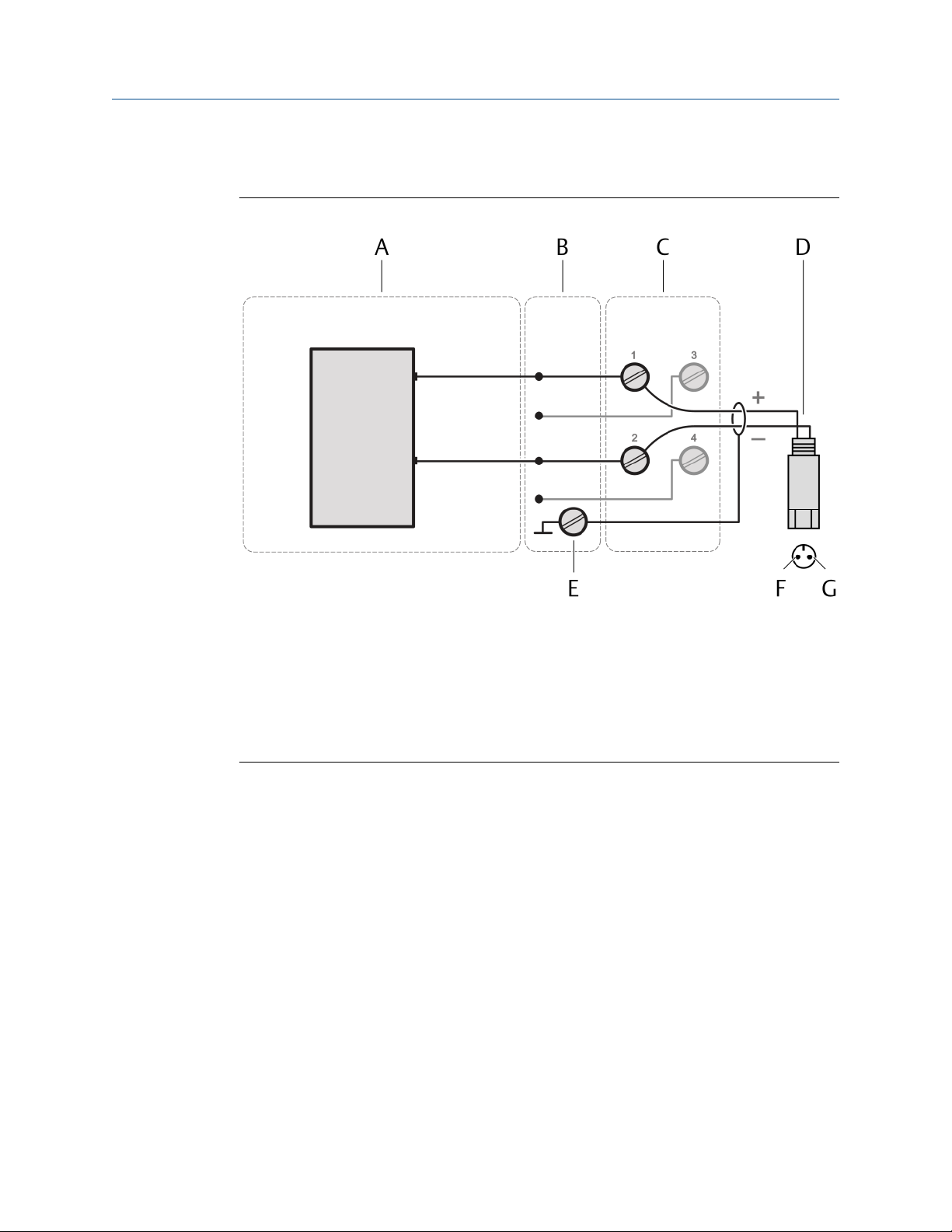
5.2.1 Connect the sensor wiring
Figure 5-7: Sensor connection
A. VI Piezo CHARM
B. CHARM Baseplate
C. CHARM Terminal Block
D. 2-wire piezoelectric sensor
E. Cable shield connection
F. Top view of the sensor connector – terminal A
G. Top view of the sensor connector – terminal B
Prerequisites
• Wire cutter
• Tool for removing the cable sheath
• Wire stripper
• Suitable screw driver for the CHARM Terminal Block screws
• Shielded sensor cable
• Observe the hints in Wiring guidelines.
Procedure
1. At opened door, lead the sensor cable through a cable gland close to the slot where
the CHARM to be connected is installed.
2. Strip the cable sheath at a length of approximately 200 mm.
3. Strip each wire at a length of approximately 10 mm.
4. Connect the wires to the CHARM Terminal Block.
50 MHM-97923-PBF, Rev. 2.5

Installation Guide Installing CHARMs hardware
MHM-97923-PBF June 2022
• Connect terminal A of the 2-wire piezoelectric sensor to terminal 1 of the
CHARM Terminal Block.
• Connect terminal B of the 2-wire piezoelectric sensor to terminal 2 of the
CHARM Terminal Block.
• Connect the cable shield to a grounding terminal (see Grounding).
5. Ensure that the cable gland, where the sensor cable is led through, is closed to keep
the IP protection class of the AMS Asset Monitor.
6. Continue with the installation or close the door (see Close the AMS Asset Monitor).
5.3 Install a VI Tach CHARM
The VI Tach CHARM is designed for the connection of magnetic pickups, output signals of
eddy current measurement chains, and Hall-effect sensors. The VI Tach CHARM is supplied
by the AMS Asset Monitor. A CHARM Terminal Block is required for the installation. See
installation guide of the VI Tach CHARM for further details. See Installing CHARMs
hardware for the general CHARM installation procedure.
MHM-97923-PBF, Rev. 2.5 51
Installing CHARMs hardware Installation Guide
June 2022 MHM-97923-PBF
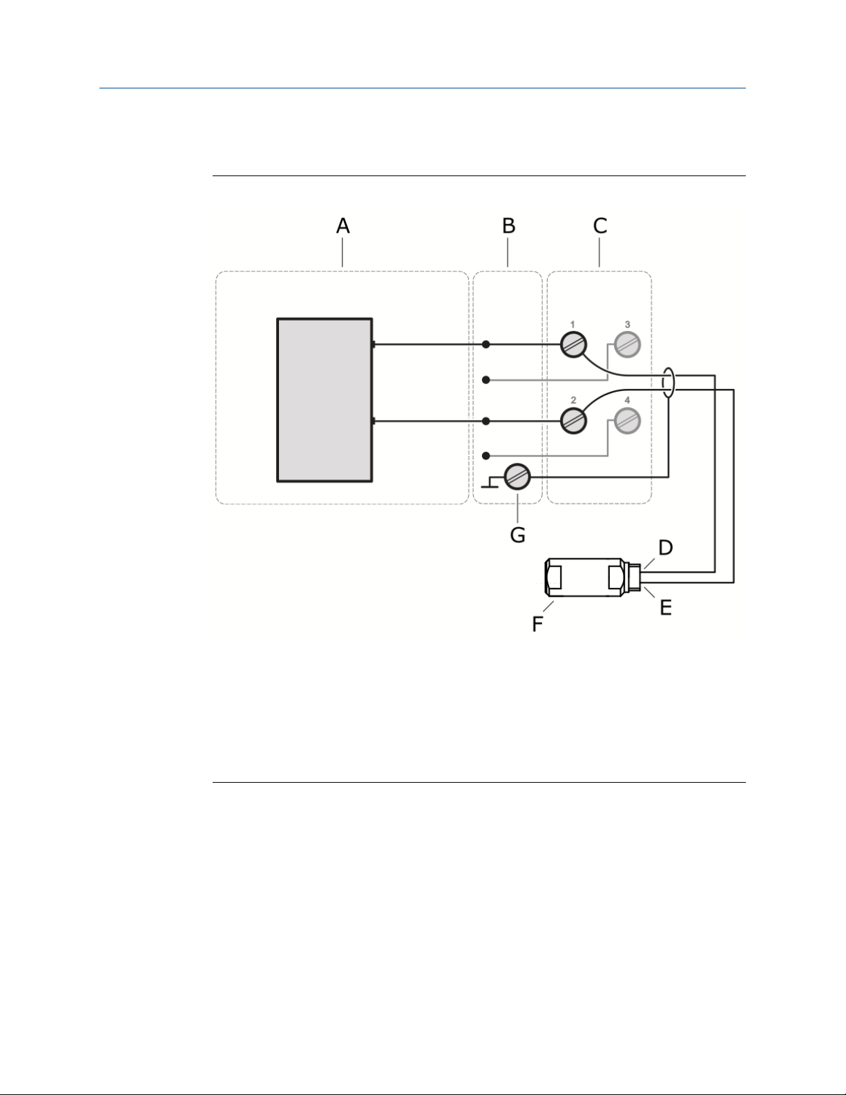
5.3.1 Connect the sensor wiring
Figure 5-8: Sensor connection – magnetic pickup
A. VI Tach CHARM
B. CHARM Baseplate
C. Standard CHARM Terminal Block
D. Signal Out
E. Signal GND
F. Magnetic pickup
G. Cable shield connection
52 MHM-97923-PBF, Rev. 2.5

Installation Guide Installing CHARMs hardware
MHM-97923-PBF June 2022
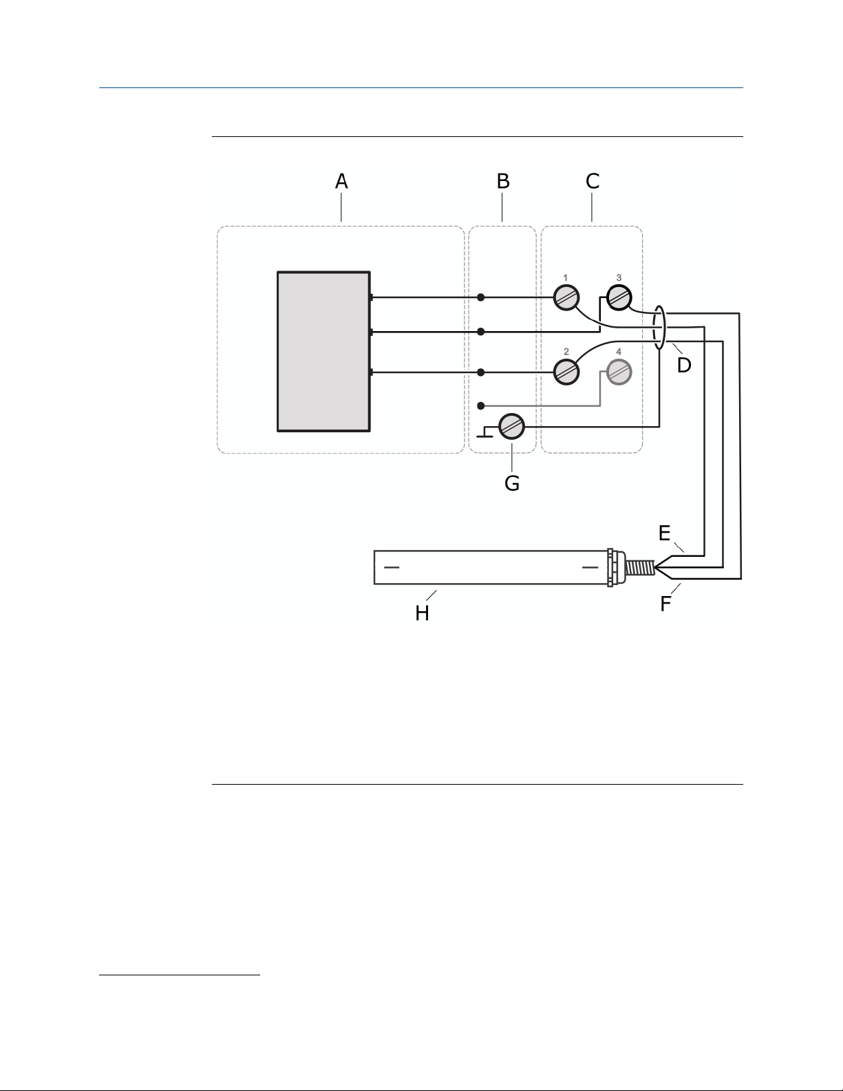
Figure 5-9: Sensor connection – output signal of an eddy current measuring chain
A. VI Tach CHARM
B. CHARM Baseplate
C. Standard CHARM Terminal Block
D. Signal GND
E. Signal OUT
F. External power supply for the eddy current measuring chain
G. Eddy current converter
H. Cable shield connection
I. Eddy current sensor
MHM-97923-PBF, Rev. 2.5 53
Installing CHARMs hardware Installation Guide
June 2022 MHM-97923-PBF
Figure 5-10: Sensor connection – Hall-effect sensor
A. VI Tach CHARM
B. CHARM Baseplate
C. Standard CHARM Terminal Block
D. GND
E. Signal output
F. +24 V power supply
G. Cable shield connection
3
H. Hall-effect sensor
Prerequisites
• Wire cutter
• Tool for removing the cable sheath
• Wire stripper
• Suitable screw driver for the CHARM Terminal Block screws
• Observe the hints in Wiring guidelines
3
Only if the cable shield is not used for signal GND and supply GND.
54 MHM-97923-PBF, Rev. 2.5
Installation Guide Installing CHARMs hardware
MHM-97923-PBF June 2022
Procedure
1. At opened door, lead the sensor cable through a cable gland close to the slot where
the CHARM to be connected is installed.
2. Strip the cable sheath at a length of approximately 200 mm.
3. Strip each wire at a length of approximately 10 mm.
4. Connect the wires to the CHARM Terminal Block.
Table 5-1:
Sensor Sensor terminals CHARM terminals
Magnetic pickup Signal Out
Signal GND
Output signal of an eddy
current measuring chain
Hall-effect sensor Signal Out
Connect the cable shield to a grounding terminal (see Grounding). With Hall-effect sensors,
only if the cable shield is not used for signal GND and supply GND.
Out
GND
GND
+24 V Power Supply
5. Ensure that the cable gland, where the signal cable is led through, is closed to keep
the IP protection class of the AMS Asset Monitor.
6. Continue with the installation or close the door (see Close the AMS Asset Monitor).
5.4 Install a VI Voltage CHARM
The VI Voltage CHARM is designed for the connection of voltage signals in the range of -24
V to +24 V. The VI Voltage CHARM is supplied by the AMS Asset Monitor. A CHARM
Terminal Block is required for the installation. See installation guide of the VI Voltage
CHARM for further details. See Installing CHARMs hardware for the general CHARM
installation procedure.
1
2
1
2
1
2
3
MHM-97923-PBF, Rev. 2.5 55
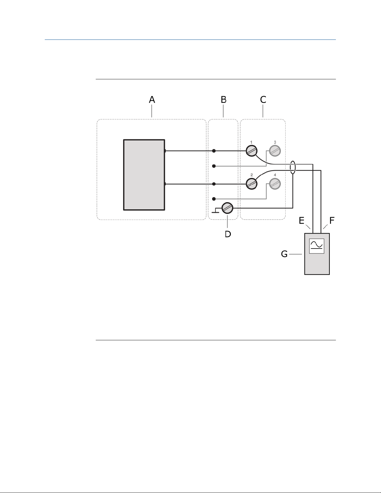
Installing CHARMs hardware Installation Guide
June 2022 MHM-97923-PBF
5.4.1 Connect the voltage input wiring
Figure 5-11: Signal connection
A. VI Voltage CHARM
B. CHARM Baseplate
C. Standard CHARM Terminal Block
D. Cable shield connection
E. Signal
F. Return
G. Voltage signal source
Prerequisites
• Wire cutter
• Tool for removing the cable sheath
• Wire stripper
• Suitable screw driver for the CHARM Terminal Block screws
• Shielded sensor cable
• Observe the hints in Wiring guidelines
56 MHM-97923-PBF, Rev. 2.5

Installation Guide Installing CHARMs hardware
MHM-97923-PBF June 2022
Procedure
1. At opened door, lead the sensor cable through a cable gland close to the slot where
the CHARM to be connected is installed.
2. Strip the cable sheath at a length of approximately 200 mm.
3. Strip each wire at a length of approximately 10 mm.
4. Connect the wires to the CHARM Terminal Block.
• Connect the signal wire of the voltage signal source to terminal 1 of the CHARM
Terminal Block.
• Connect the GND of the voltage signal source to terminal 2 of the CHARM
Terminal Block.
• Connect the cable shield to a ground terminal (see Grounding).
5. Ensure that the cable gland, where the sensor cable is led through, is closed to keep
the IP protection class of the AMS Asset Monitor.
6. Continue with the installation or close the door (see Close the AMS Asset Monitor).
5.5 Install a DO 24 V DC High-Side CHARM
The DO 24 V DC High-Side CHARM is a discrete output CHARM for momentary output
signals or continuous pulse outputs. The CHARM is supplied by the AMS Asset Monitor. A
CHARM Terminal Block is required for the installation. If a relay output is required use the
CHARM Relay Output Terminal Block. See Installing CHARMs hardware for the general
CHARM installation procedure.
MHM-97923-PBF, Rev. 2.5 57

Installing CHARMs hardware Installation Guide
June 2022 MHM-97923-PBF
5.5.1 Connect the output signal wiring
Figure 5-12: Signal connection
A. Digital Output DO 24 V DC High-Side CHARM
B. CHARM Baseplate
C. CHARM Terminal Block
D. Field device with digital input
E. Cable shield connection
Prerequisites
• Wire cutter
• Tool for removing the cable sheath
• Wire stripper
• Suitable screw driver for the CHARM Terminal Block screws
• Observe the hints in Wiring guidelines.
Procedure
1. At opened door, lead the signal cable through a cable gland close to the slot where
the CHARM to be connected is installed.
2. Strip the cable sheath at a length of approximately 200 mm.
3. Strip each wire at a length of approximately 10 mm.
4. Connect the wires to the CHARM Terminal Block.
• Connect terminal + of the digital input of the field device to terminal 1 of the
CHARM Terminal Block.
58 MHM-97923-PBF, Rev. 2.5

Installation Guide Installing CHARMs hardware
MHM-97923-PBF June 2022
• Connect terminal - of the digital input of the field device to terminal 2 of the
CHARM Terminal Block.
• Connect the cable shield to a grounding terminal (see Grounding).
5. Ensure that the cable gland, where the signal cable is led through, is closed to keep
the IP protection class of the AMS Asset Monitor.
6. Continue with the installation or close the door (see Close the AMS Asset Monitor).
5.5.2 Connect the relay output wiring
Figure 5-13: Relay output connection
A. Digital Output DO 24 V DC High-Side CHARM
B. CHARM Baseplate
C. CHARM Relay Output Terminal Block
D. Relay output: NC (normally closed)
E. Relay output: Common
F. Relay output: NO (normally open)
G. Cable shield connection
Prerequisites
• Wire cutter
• Tool for removing the cable sheath
• Wire stripper
• Suitable screw driver for the CHARM Relay Output Terminal Block screws
• Observe the hints in Wiring guidelines.
MHM-97923-PBF, Rev. 2.5 59

Installing CHARMs hardware Installation Guide
June 2022 MHM-97923-PBF
DANGER
The KL4502X1-MA1 CHARM Relay Output Terminal Block may have hazardous live
voltages on its output terminals. This terminal block is capable to switch field power of 250
V AC. Ensure that proper safety precautions, such as de-energizing field power, are
observed during installation, maintenance, or any time wiring changes are made to the
CHARM Relay Output Terminal Block.
Permissible relay contact ratings:
• 28.8 VDC at 5 A switching current
• 48 VDC at 0.4 A switching current
• 250 VAC at 5 A switching current
See the documentation provided with the CHARM Relay Output Terminal Block for further
details and technical data.
Procedure
1. At opened door, lead the signal cable through a cable gland close to the slot where
the CHARM to be connected is installed.
2. Strip the cable sheath at a length of approximately 200 mm.
3. Strip each wire at a length of approximately 10 mm.
4. Connect the wires to the CHARM Relay Output Terminal Block.
5. Ensure that the cable gland, where the signal cable is led through, is closed to keep
the IP protection class of the AMS Asset Monitor.
6. Continue with the installation or close the door (see Close the AMS Asset Monitor).
5.6 Install a DI 24 V DC Low-Side Sens CHARM
The DI 24 V DC Low-Side Sens CHARM is a discrete input CHARM for sensing relay and
switch contact closure. The CHARM is supplied by the AMS Asset Monitor. A CHARM
Terminal Block is required for the installation. See Installing CHARMs hardware for the
general CHARM installation procedure.
This CHARM supports line fault detection for detecting open or short circuits in the field
wiring when external line fault resistors are used. To use line fault detection:
• Enable line fault detection in the CHARM's configuration.
• Connect the dry contact to a 12 kΩ resistor in parallel for open circuit detection and a
2.4 kΩ resistor in series for short circuit detection. See Figure 5-14 for a connection
diagram.
Note
Connect the resistors as closely as possible to the signal input to ensure proper line
fault detection.
60 MHM-97923-PBF, Rev. 2.5

Installation Guide Installing CHARMs hardware
MHM-97923-PBF June 2022
5.6.1 Connect the input signal wiring
Figure 5-14: Signal connection
A. Digital Input DI 24 V DC Low-Side Sense (dry contact) CHARM
B. CHARM Baseplate
C. CHARM Terminal Block
D. Field device with digital output
E. Cable shield connection
F. Connection option for line fault detection
Prerequisites
• Wire cutter
• Tool for removing the cable sheath
• Wire stripper
• Suitable screw driver for the CHARM Terminal Block screws
• Observe the hints in Wiring guidelines.
MHM-97923-PBF, Rev. 2.5 61

Installing CHARMs hardware Installation Guide
June 2022 MHM-97923-PBF
Procedure
1. At opened door, lead the signal cable through a cable gland close to the slot where
the CHARM to be connected is installed.
2. Strip the cable sheath at a length of approximately 200 mm.
3. Strip each wire at a length of approximately 10 mm.
4. Connect the wires to the CHARM Terminal Block.
• Connect terminal + of the digital output of the field device to terminal 1 of the
CHARM Terminal Block.
• Connect terminal - of the digital output of the field device to terminal 2 of the
CHARM Terminal Block.
• Connect the cable shield to a grounding terminal (see Grounding).
5. Ensure that the cable gland, where the signal cable is led through, is closed to keep
the IP protection class of the AMS Asset Monitor.
6. Continue with the installation or close the door (see Close the AMS Asset Monitor).
5.7 Install a AI 4 to 20 mA CHARM
The AI 4 to 20 mA CHARM is an analog input CHARM for 4 to 20 mA signals. The CHARM is
supplied by the AMS Asset Monitor. A CHARM Terminal Block is required for the
installation. Self-powered or loop-powered field devices with an analog output can be
connected. See Installing CHARMs hardware for the general CHARM installation
procedure.
Note
HART (Highway Addressable Remote Transducer) is not supported if the 4 to 20 mA AI
CHARM is installed in an AMS Asset Monitor.
62 MHM-97923-PBF, Rev. 2.5

Installation Guide Installing CHARMs hardware
MHM-97923-PBF June 2022
5.7.1 Connect the input signal wiring – self-powered
Figure 5-15: Signal connection
A. Analog Input AI 4 to 20 mA CHARM
B. CHARM Baseplate
C. CHARM Terminal Block
D. Field device with analog output
E. Cable shield connection
Prerequisites
• Wire cutter
• Tool for removing the cable sheath
• Wire stripper
• Suitable screw driver for the CHARM Terminal Block screws
• Observe the hints in Wiring guidelines.
Procedure
1. At opened door, lead the signal cable through a cable gland close to the slot where
the CHARM to be connected is installed.
2. Strip the cable sheath at a length of approximately 200 mm.
3. Strip each wire at a length of approximately 10 mm.
4. Connect the wires to the CHARM Terminal Block.
• Connect terminal + of the analog output of the field device to terminal 2 of the
CHARM Terminal Block.
MHM-97923-PBF, Rev. 2.5 63
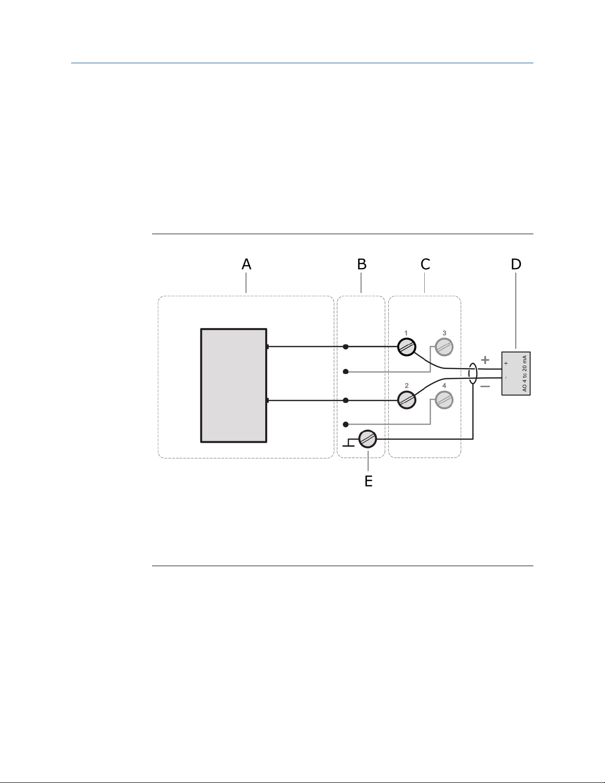
Installing CHARMs hardware Installation Guide
June 2022 MHM-97923-PBF
• Connect terminal - of the analog output of the field device to terminal 4 of the
CHARM Terminal Block.
• Connect the cable shield to a grounding terminal (see Grounding).
5. Ensure that the cable gland, where the signal cable is led through, is closed to keep
the IP protection class of the AMS Asset Monitor.
6. Continue with the installation or close the door (see Close the AMS Asset Monitor).
5.7.2 Connect the input signal wiring – loop-powered
Figure 5-16: Signal connection
A. Analog Input AI 4 to 20 mA CHARM
B. CHARM Baseplate
C. CHARM Terminal Block
D. Field device with analog output
E. Cable shield connection
Technical data loop-power:
• 15.0 V minimum at 20 mA with 24 VDC input power
• Current limited to 30 mA maximum
Prerequisites
• Wire cutter
• Tool for removing the cable sheath
• Wire stripper
64 MHM-97923-PBF, Rev. 2.5

Installation Guide Installing CHARMs hardware
MHM-97923-PBF June 2022
• Suitable screw driver for the CHARM Terminal Block screws
• Observe the hints in Wiring guidelines.
Procedure
1. At opened door, lead the signal cable through a cable gland close to the slot where
the CHARM to be connected is installed.
2. Strip the cable sheath at a length of approximately 200 mm.
3. Strip each wire at a length of approximately 10 mm.
4. Connect the wires to the CHARM Terminal Block.
• Connect terminal + of the analog output of the field device to terminal 1 of the
CHARM Terminal Block.
• Connect terminal - of the analog output of the field device to terminal 2 of the
CHARM Terminal Block.
• Connect the cable shield to a grounding terminal (see Grounding).
5. Ensure that the cable gland, where the signal cable is led through, is closed to keep
the IP protection class of the AMS Asset Monitor.
6. Continue with the installation or close the door (see Close the AMS Asset Monitor).
5.8 Install a RTD CHARM
The RTD CHARM is a CHARM for temperature measurement with RTD sensors. The
CHARM is supplied by the AMS Asset Monitor. A CHARM Terminal Block is required for the
installation. See Installing CHARMs hardware for the general CHARM installation
procedure.
MHM-97923-PBF, Rev. 2.5 65
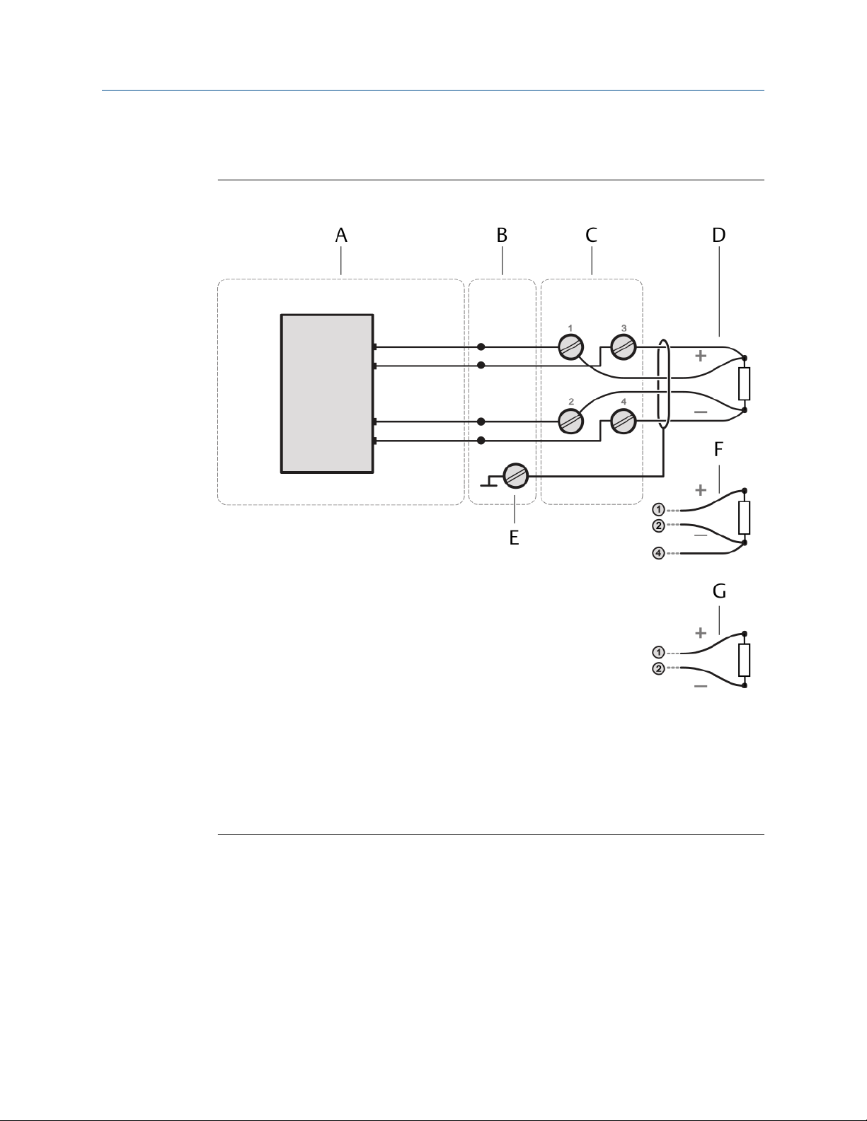
Installing CHARMs hardware Installation Guide
June 2022 MHM-97923-PBF
5.8.1 Connect the sensor wiring
Figure 5-17: Sensor connection
A. RTD CHARM
B. CHARM Baseplate
C. CHARM Terminal Block
D. 4-wire RTD
E. Cable shield connection
F. 3-wire RTD
G. 2-wire RTD
Prerequisites
• Wire cutter
• Tool for removing the cable sheath
• Wire stripper
• Suitable screw driver for the CHARM Terminal Block screws
• Observe the hints in Wiring guidelines.
66 MHM-97923-PBF, Rev. 2.5

Installation Guide Installing CHARMs hardware
MHM-97923-PBF June 2022
Procedure
1. At opened door, lead the sensor cable through a cable gland close to the slot where
the CHARM to be connected is installed.
2. Strip the cable sheath at a length of approximately 200 mm.
3. Strip each wire at a length of approximately 10 mm.
4. Connect the wires to the CHARM Terminal Block.
Table 5-2: RTD connections
RTD Type RTD Terminals RTD CHARM Terminals
4-wire Sensor signal 1
Sensor signal 2
Supply + 3
Supply - 4
3-wire Supply + and Sensor signal 1
Sensor signal 2
Supply - 4
2-wire Supply + and sensor signal 1
Supply - and sensor signal 2
Connect the cable shield to a grounding terminal (see Grounding).
5. Ensure that the cable gland, where the signal cable is led through, is closed to keep
the IP protection class of the AMS Asset Monitor.
6. Continue with the installation or close the door (see Close the AMS Asset Monitor).
5.9 Install a Thermocouple/mV input CHARM
The Thermocouple/mV input CHARM is a CHARM for temperature measurement with
thermocouples. The CHARM is supplied by the AMS Asset Monitor. A CHARM
Thermocouple/mV Terminal Block is required for the installation. See Installing CHARMs
hardware for the general CHARM installation procedure.
MHM-97923-PBF, Rev. 2.5 67
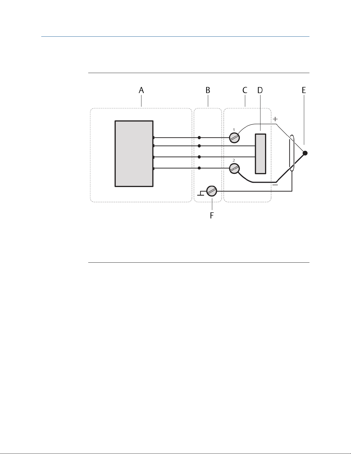
Installing CHARMs hardware Installation Guide
June 2022 MHM-97923-PBF
5.9.1 Connect the sensor wiring
Figure 5-18: Sensor connection
A. Thermocouple CHARM
B. CHARM Baseplate
C. CHARM Thermocouple /mV Terminal Block
D. Internal RTD
E. Cable shield connection
Prerequisites
• Wire cutter
• Tool for removing the cable sheath
• Wire stripper
• Suitable screw driver for the CHARM Terminal Block screws
• Observe the hints in Wiring guidelines.
Procedure
1. At opened door, lead the sensor cable through a cable gland close to the slot where
the CHARM to be connected is installed.
2. Strip the cable sheath at a length of approximately 200 mm.
3. Strip each wire at a length of approximately 10 mm.
4. Connect the wires to the CHARM Thermocouple/mV Terminal Block.
• Connect terminal + of the thermocouple to terminal 1 of the CHARM
Thermocouple/mV Terminal Block.
68 MHM-97923-PBF, Rev. 2.5
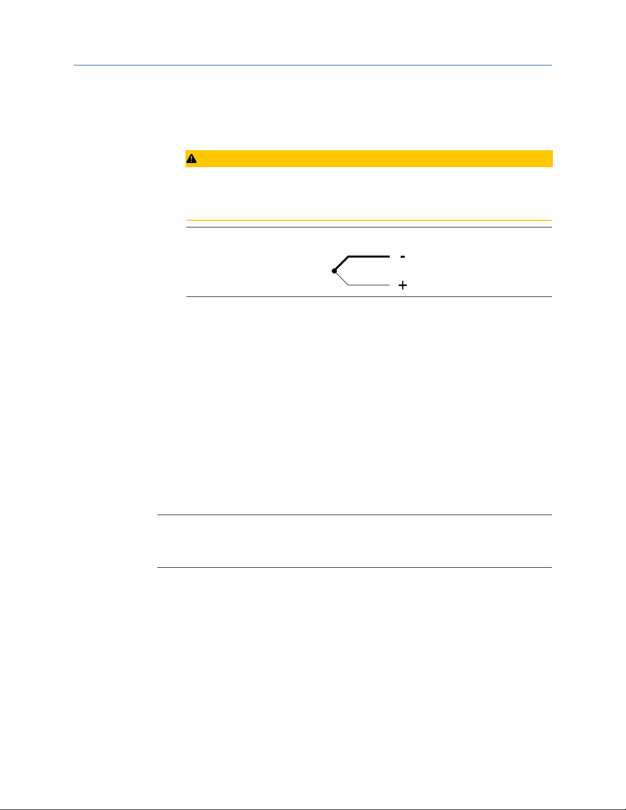
Installation Guide Installing CHARMs hardware
MHM-97923-PBF June 2022
• Connect terminal - of the thermocouple to terminal 2 of the CHARM
Thermocouple/mV Terminal Block.
• Connect the cable shield to a grounding terminal (see Grounding).
CAUTION
Ensure that the thermocouple is always connected with the right polarity. The
thicker line of the thermocouple symbol indicates the minus connection. The thin
line marks the plus connection.
Figure 5-19: General thermocouple symbol
Thermocouple types and their polarity are identified by colors. The different
coloring of thermocouple sheaths and wires are subject to various national
standards. Check the polarity of the thermocouple before connecting it to the
CHARM.
5. Ensure that the cable gland, where the signal cable is led through, is closed to keep
the IP protection class of the AMS Asset Monitor.
6. Continue with the installation or close the door (see Close the AMS Asset Monitor).
5.10 Install the Address Plug
The AMS Asset Monitor is equipped with a dedicated slot for an Address Plug. The Address
Plug is required for proper function of the installed CHARMs.
A CHARM Address Terminal Block is required for the installation. See the documentation
provided with the Address Plug and the Address Terminal Block for further details.
Note
The providing of field power to isolated CHARMs installed in CHARM Fused Injected Power
Terminal Blocks is not supported by a CHARM Address Terminal Block installed in the AMS
Asset Monitor.
Procedure
1. Open the AMS Asset Monitor (see Open the AMS Asset Monitor), if not already
done.
2. Flip down the CHARM labeling component (see Figure 4-3 for location), if there is
one.
3. Hook the CHARM Address Terminal Block into the lower part of the address slot, the
right-most slot (see Figure 5-1), and gently push it in.
The CHARM Address Terminal Block locks with an audible click.
4. Ensure that the latch of the Address Terminal Block is in the open position as shown
in Figure 5-20. If the latch is in the closed position, use a suitable flat-tip screwdriver
to open it.
MHM-97923-PBF, Rev. 2.5 69
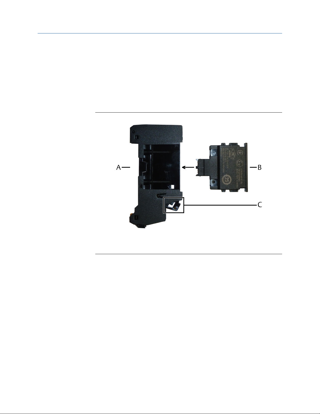
Installing CHARMs hardware Installation Guide
June 2022 MHM-97923-PBF
a) Insert the screwdriver into the latch.
b) Move the screwdriver down to switch the latch to the open position.
c) Remove the screwdriver.
5. Gently push the Address Plug into the CHARM Address Terminal Block installed
before. The Address Plug locks with an audible click – the latch of the Address
Terminal Block flips in the close position.
The Address Plug only fits in one direction.
Figure 5-20: Address Plug installation
A. CHARM Address Terminal Block
B. Address Plug
C. Latch in open position
6. Continue with the installation or close the door (Close the AMS Asset Monitor).
5.11 Label the installed CHARMs
The CHARM labeling component consists of a label support that holds a label and its
protective plastic cover. Remove the label support from the AMS Asset Monitor before
writing or typing the CHARM IDs on the label.
70 MHM-97923-PBF, Rev. 2.5
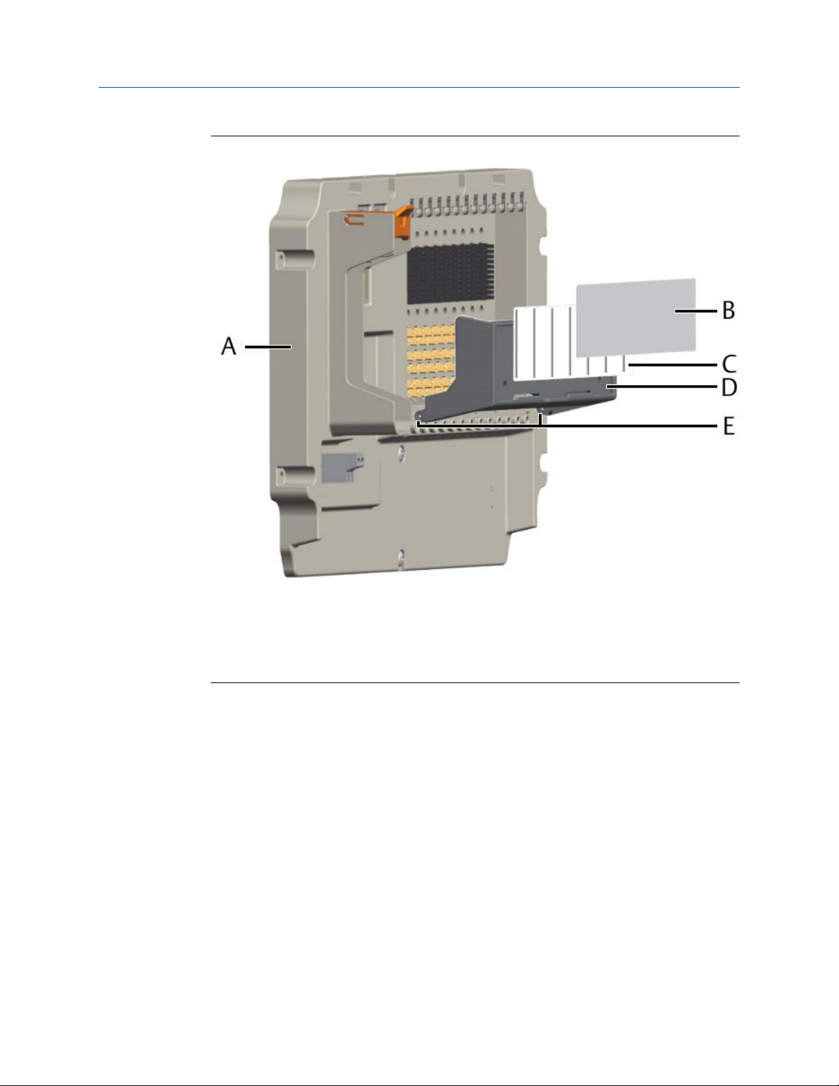
Installation Guide Installing CHARMs hardware
MHM-97923-PBF June 2022
Figure 5-21: CHARM labeling component
A. Baseplate
B. Protective cover
C. Label
D. Label support
E. Hinge
Procedure
1. Press the label support at the top hinge and remove it from the hinge post.
2. Lift the support off from the bottom hinge post.
The label support is now free.
3. Slide the protective plastic cover off from the label being careful not to bend or fold
it.
4. Slide the label from the label support being careful not to bend or fold it.
5. Write or type the CHARM IDs in the preformatted areas on the label.
6. Slide the completed label back into the support from the top, being sure that the
label passes under the label retainers and is properly seated under the top and
bottom corner tabs.
7. Repeat the previous step and insert the protective plastic cover over the label.
8. Reattach the label support to the baseplate.
MHM-97923-PBF, Rev. 2.5 71

Installing CHARMs hardware Installation Guide
June 2022 MHM-97923-PBF
5.12 CHARM Protection Cover
Use the CHARM Protection Cover to protect unused CHARM Terminal Blocks from
damage. The CHARM Protection Cover does not affect the key setting on the CHARM
Terminal Block. See documentation provided with the Protection Cover for installation
and further details.
72 MHM-97923-PBF, Rev. 2.5
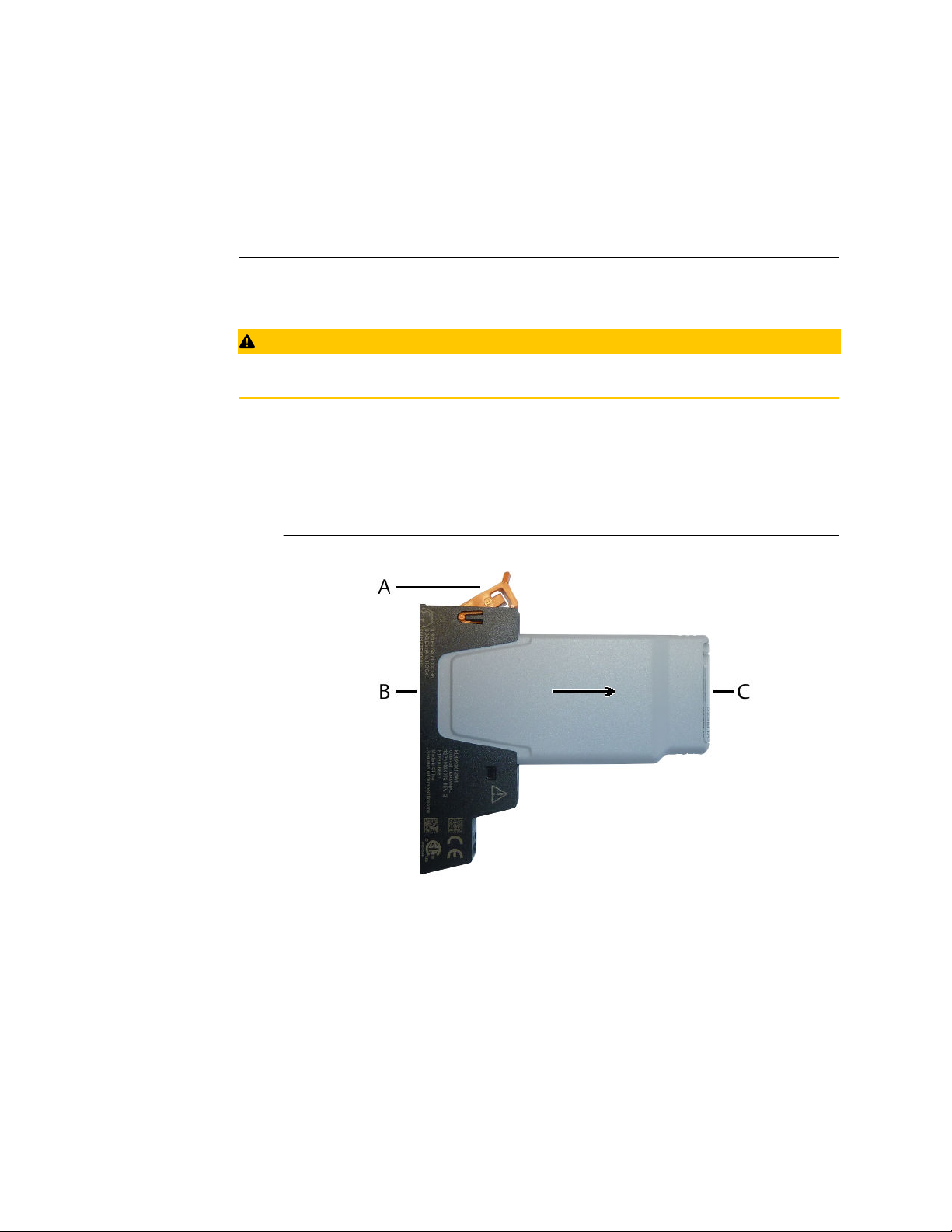
Installation Guide Removing CHARMs hardware
MHM-97923-PBF June 2022
6 Removing CHARMs hardware
Follow these steps to remove CHARMs hardware from the AMS Asset Monitor.
Note
CHARMs and Terminal Blocks are hot-swappable. It is not necessary to switch off the
system's power supply before installing or removing CHARMs or Terminal Blocks.
CAUTION
Any work on the system may impair asset health monitoring and machine protection.
6.1 Remove a CHARM
Procedure
1. To remove a CHARM from its Terminal Block, push the latch of the Terminal Block
upwards.
Figure 6-1: Remove a CHARM
A. Latch
B. Terminal Block
C. CHARM
The CHARM is unlocked.
2. Pull the CHARM out of the terminal block to remove it completely.
MHM-97923-PBF, Rev. 2.5 73

Removing CHARMs hardware Installation Guide
June 2022 MHM-97923-PBF
6.2 Remove a Terminal Block
Follow these steps to remove a CHARM (Standard), Thermocouple/mV, Address, or Relay
Output Terminal Block.
Prerequisites
• Suitable flat-tip screwdriver to unlock the Terminal Block.
• Suitable flat-tip screwdriver for the terminal screws.
DANGER
Ensure that no device, such as a CHARM or an Address Plug, is installed in the Terminal
Block to be removed. Removing a Terminal Block with an installed device might damage
Baseplate, Terminal Block, and the installed device.
Procedure
1. Flip down the CHARM labeling component - if one is installed.
2. Disconnect all wires connected to the Terminal Block to be removed.
3. Grip the upper part of the Terminal Block with two fingers.
4. Press down the terminal block release button with a suitable flat-tip screwdriver and
hold it pressed down.
Figure 6-2: Remove a Terminal Block
The Terminal Block is unlocked.
5. Pull the Terminal Block out of the baseplate.
6. Release the release button.
74 MHM-97923-PBF, Rev. 2.5

Installation Guide Removing CHARMs hardware
MHM-97923-PBF June 2022
7. Emerson recommends resetting the keying posts of removed CHARM Terminal
Blocks to prepare it for the installation of other CHARM types. For resetting the key
settings see Installing CHARMs hardware. The Thermocouple/mV Terminal Block
has a fixed key setting and cannot be reset.
6.3 Remove the Address Plug
Procedure
1. Flip down the CHARM labeling component (see Figure 5-21 for location), if there is
one.
2. To remove the Address Plug, insert a flat-tip screwdriver into the latch of the
CHARM Address Terminal Block. See Figure 5-20 for location of the latch.
3. Move the screwdriver down to unlock the Address Plug.
4. Pull the Address Plug out of the Address Terminal Block to remove it completely.
6.4 Remove the CHARM Address Terminal Block
The procedure is the same as for the CHARM Terminal Blocks. See Remove a Terminal
Block.
6.5 Remove the +24 V DC Power Module
CAUTION
Any work on the system may impair asset health monitoring and machine protection.
Procedure
1. To remove the +24 V DC Power Module, push the latch of the slot for the +24 V DC
Power Module upwards.
The +24 V DC Power Module is unlocked.
2. Pull the +24 V DC Power Module out of the slot to remove it completely.
MHM-97923-PBF, Rev. 2.5 75

Removing CHARMs hardware Installation Guide
June 2022 MHM-97923-PBF
76 MHM-97923-PBF, Rev. 2.5

Installation Guide Hazardous location installation
MHM-97923-PBF June 2022
7 Hazardous location installation
Version 2.1
7.1 General installation requirements
The AMS Asset Monitor must be solely connected to SELV/PELV electrical circuits to meet
the requirements for explosion protection. This also applies to all devices connected to the
AMS Asset Monitor. Exceptions are explicitly stated. In version 1.0, the Relay Terminal
Block is approved for voltages up to 250 V. An installation in Zone 2 is permitted if the
conditions stated in the following chapters are met.
Ensure a distance of at least 50 mm between the outer edge of the terminals used for
intrinsically safe field installation wiring and all other circuits or wirings.
Use wire types and wiring apparatus with a temperature rating ≥70°C.
7.2 Connection requirements
The wire cross-section of the used cables must be within the range of 0.34<F<2.5 mm2.
Use ferrules at stranded conductors.
Connect the shield of the Ethernet cable to ground at the remote station. Integrate the
grounding of all cable shields into to potential equalization system.
All used connectors (Ethernet- and power supply terminals) must be locked. Ensure this
besides using suitable connectors by using cable glands, suitable for the respective cable
diameter approved for the use in potentially explosive atmospheres.
Only use the USB port at open field housing, which requires a hazard-free environment.
7.3 Special conditions of safe use
1. The end user shall ensure appropriate earthing upon installation. The transmission
resistance for SELV/PELV circuits must not exceed 109 Ω. For the grounding of
hazardous live voltages comply with the additional requirements of protective
grounding.
2. Electrostatic charging during operation and maintenance has to be excluded. The
device shall only be installed in areas where operational and process related
electrostatic charges are not present.
3. Final acceptance of this equipment when installed is subject to the jurisdiction of
the local inspection authority. The DeltaV CHARMs have their own component
certification to be assessed within the overall system.
The following warnings must be observed:
• WARNING: EXPLOSION HAZARD - DO NOT CONNECT OR DISCONNECT WHILE
CIRCUITS ARE LIVE UNLESS AREA IS KNOWN TO BE NON-HAZARDOUS
MHM-97923-PBF, Rev. 2.5 77

Hazardous location installation Installation Guide
June 2022 MHM-97923-PBF
AVERTISSEMENT: RISQUE D’EXPLOSION- NE PAS CONNECTER OU DECONNECTER TANT
QUE LES CIRCUITS SONT SUR TENSION SEULEMENT SI LA ZONE EST CONNU POUR ÉTRE
NON DANGEREUX
• WARNING: DO NOT USE USB PORT UNLESS THE AREA IS KNOWN TO BE NON-
HAZARDOUS
AVERTISSEMENT: NE PAS UTILISER PORT USB SEULEMENT SI LA ZONE EST CONNU
POUR ÉTRE NON DANGEREUX
• WARNING: EXPLOSION HAZARD. DO NOT REMOVE OR REPLACE CHARM MODULES
UNLESS POWER HAS BEEN DISCONNECTED OR THE AREA IS FREE OF IGNITIBLE
CONCENTRATIONS
AVERTISSEMENT: RISQUE D’EXPLOSION. NE PAS ENLEVER OU REMPLACER LES
MODULES DE CHARME À MOINS QUE L'ALIMENTATION SOIT DÉCONNECTÉE OU QUE
LA ZONE SOIT EXEMPT DE CONCENTRATIONS IGNITIBLES
• WARNING: SUBSTITUTION OF COMPONENTS MAY IMPAIR INTRINSIC SAFETY
AVERTISSEMENT: LA SUBSTITUTION DE COMPOSANTS PEUT COMPROMETTRE LA
SECURITE INTRINSEQUE
• WARNING: DO NOT OPEN ENCLOSURE IN A DUST HAZARDOUS AREA
AVERTISSEMENT: NE PAS OUVRIR DANS UNE ZONE À RISQUE D’EXPLOSION DE
POUSSIÈRES
7.4 Technical data, explosion protection
The AMS Asset Monitor is checked and certified for the following, if connected to SELV/
PELV – electrical circuits for use in potentially explosive atmospheres:
IECEx/ATEX/CSA
Type of protection non-sparking nA in combination with nC
and [ic], depending on the installed
CHARMs
Identification IECEx/ATEX II 3G Ex ec nA nC [ic] IIC T4 Gc
III 2D Ex tb [ic] IIIC T75°C Db
CSA Class I, Zone 2 Ex/AEx ec nA nC [ic] IIC T4
Gc
Class I, Div 2 Group A, B, C, D T4
Zone 22 Ex/AEx tc [ic] IIIC T75°C Dc
Class II, Div 2 Group F, G T75°C
Class III
Temperature range -40°C < Tamb < 55°C
Standards IECEx IEC 60079-0:2017; Edition 7.0
IEC 60079-7:2017; Edition 5.1
IEC 60079-11:2011; Edition 6.0
IEC 60079-15:2010; Edition 4.0
IEC 60079-31:2013; Edition 2.0
78 MHM-97923-PBF, Rev. 2.5

Installation Guide Hazardous location installation
MHM-97923-PBF June 2022
IECEx/ATEX/CSA
ATEX EN IEC 60079-0:2018
EN IEC 60079-7:2015/A1:2018
EN 60079-11:2012
EN 60079-15:2010
EN 60079-31:2014
CSA CAN/CSA-C22.2 No. 0-10
CAN/CSA-C22.2 No. 61010-1:12 + Amd
1-18
CAN/CSA C22.2 No. 94.2-15
CAN/CSA-C22.2 No. 60079-0:15
CAN/CSA C22.2 No. 60079-0:19
CAN/CSA-C22.2 No. 60079-11:14
CAN/CSA-22.2 No. 60079-15:16
CAN/CSA C22.2 No. 213-17
CAN/CSA-C22.2 No. 60529:16
IEC 60529:2013 + COR2:2015
NEMA ANSI/IEC 60529-2004 (R2011)
ANSI/UL 50E (Second Edition)
ANSI/UL 61010-1 (Third Edition)
ANSI/UL 121201-2017 (Ninth Edition
(R2019))
ANSI/UL 60079-0-2019 (Seventh Edition)
ANSI/UL 60079-11-2014 (Sixth Edition)
ANSI/UL 60079-15-2013 (Fourth Edition
(R2017))
IECEx approval number
ATEX approval number BVS 20 ATEX E 001 X
CSA approval number 19CA70218089 X
7.5 Revision history
Version Date Remarks/Changes
1.0 30. April 2020 Initial version
2.0 24. February 2021 Update technical data
2.1 18. May 2021 Update certification
IECEx BVS 20.0001X
Dust hazardous area
certification
MHM-97923-PBF, Rev. 2.5 79

Hazardous location installation Installation Guide
June 2022 MHM-97923-PBF
80 MHM-97923-PBF, Rev. 2.5
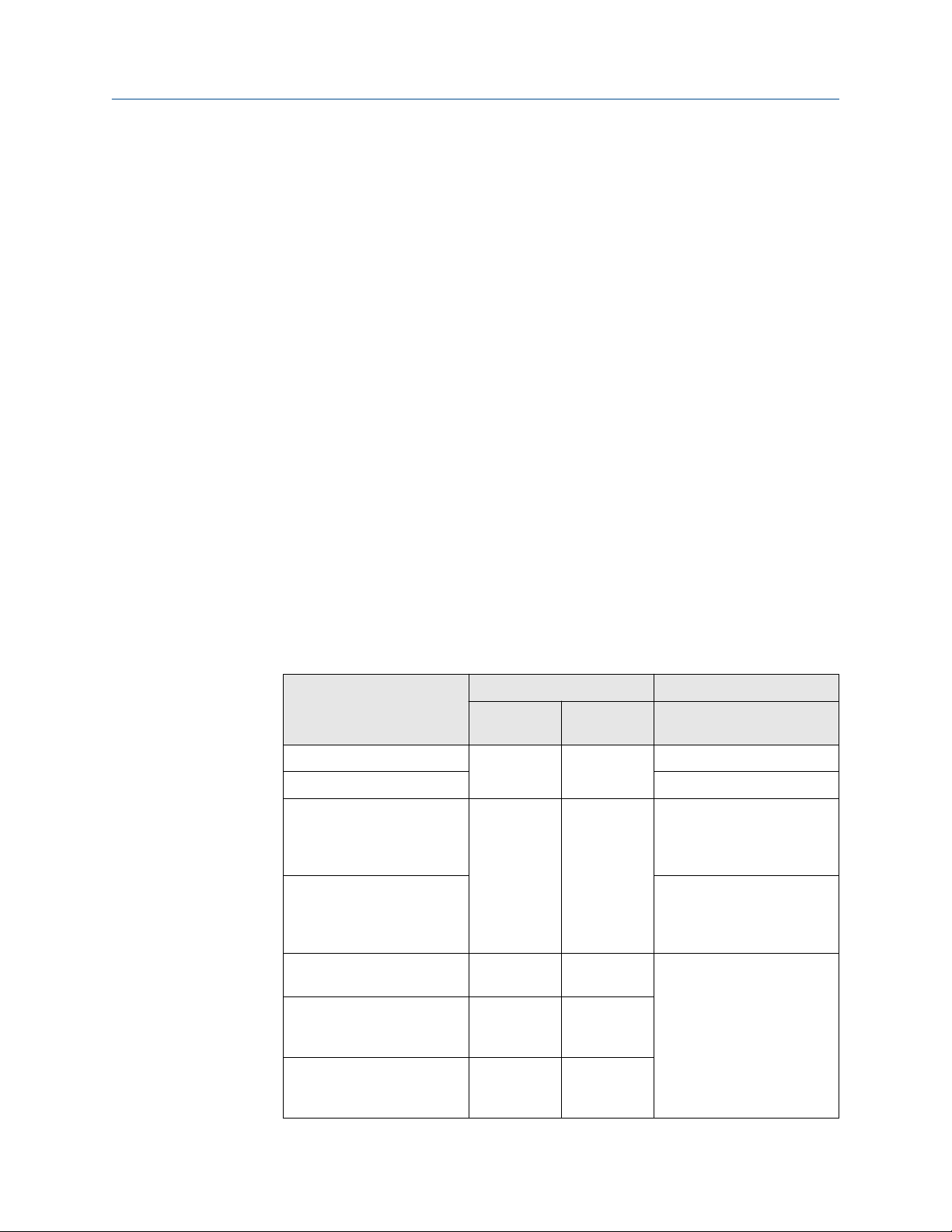
Installation Guide Maintenance, troubleshooting, replacement and repair
MHM-97923-PBF June 2022
8 Maintenance, troubleshooting,
replacement and repair
8.1 Maintenance
The AMS Asset Monitor does not require any maintenance during normal operation.
8.2 Troubleshooting
Follow these first troubleshooting steps in case of an unexpected behavior of an AMS Asset
Monitor.
Procedure
1. Connect your configuration device to the suspicious AMS Asset Monitor and open
AMS Asset Monitor Web Interface.
If the AMS Asset Monitor does not response, reset it. See AMS Asset Monitor
operating manual for how to reset the device.
2. Check the firmware version and update the firmware if a newer version is available.
3. Check the status light at the front of the AMS Asset Monitor. Table 8-1 explains the
possible status indications.
Table 8-1: Meaning of the status light
Event Status light Recommendation
Color Blinking
pattern
No fault detected Green Solid ---
Health value is good (≥ 90%) ---
Configuration required Green Fast flashing
(1 per 500
milliseconds
seconds)
Maintenance mode1 is active Open AMS Asset Monitor
Health value is ≥60% and
<90% (Advice state)
Health value is ≥30% and
<60% (Warning state)
Health value is <30% (Critical
state)
Red Solid Open AMS Asset Monitor
Red Slow flashing
(1 per 2
seconds)
Red Fast flashing
(1 per 500
milliseconds)
Open AMS Asset Monitor
Web Interface to check the
configuration on
inconsistencies.
Web Interface to check
whether an installed CHARM
is disabled.
Web Interface to get
recommendations on how to
solve the issue.
MHM-97923-PBF, Rev. 2.5 81
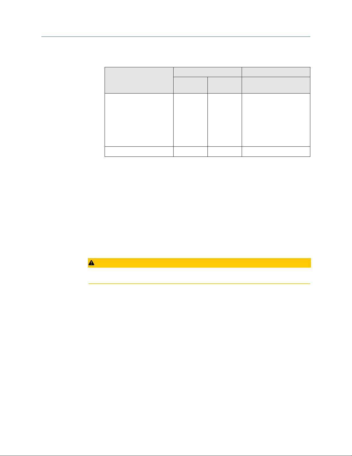
Maintenance, troubleshooting, replacement and repair Installation Guide
June 2022 MHM-97923-PBF
Table 8-1: Meaning of the status light
Event Status light Recommendation
Color Blinking
CHARM channel fault or
hardware error
No supply voltage --- Off Check the power supply.
At least one of the installed CHARMs is disabled.
1
Red Slow flashing
8.3 Replacement and repair
In case of a defect, several components of the AMS Asset Monitor can be replaced on-site.
It is not possible to repair defective CHARMs, +24 V DC Power Modules, and AMS Asset
Monitors.
(continued)
pattern
(1 per 2
seconds)
Check wiring and associated
field device. If wiring and
device are correct, replace
the CHARM. This pattern can
also occur if an unconfigured
CHARM with no connected
device is installed in the AMS
Asset Monitor.
8.3.1
Replace a defective +24 V DC Power Module
In case of a defect, replace the +24 V DC Power Module.
CAUTION
Any work on the system may impair asset health monitoring and machine protection.
Prerequisites
• Spare +24 V DC Power Module
Procedure
1. Open the door of the AMS Asset Monitor.
2. Switch the power supply of the AMS Asset Monitor off.
3. Remove the defective +24 V DC Power Module.
See Remove the +24 V DC Power Module for details.
4. Install the new +24 V DC Power Module.
See Install the +24 V DC Power Module for details.
5. Switch on the power supply of the AMS Asset Monitor.
6. Check the operational readiness to complete the replacement of the +24 V DC
Power Module.
82 MHM-97923-PBF, Rev. 2.5

Installation Guide Maintenance, troubleshooting, replacement and repair
MHM-97923-PBF June 2022
The LED on the front of the +24 V DC Power Module lights solid green if no fault is
detected.
7. Close the door of the AMS Asset Monitor.
8.3.2 Replace a defective CHARM
In case of a defect, replace the defective CHARM.
CAUTION
Any work on the system may impair asset health monitoring and machine protection.
Prerequisites
• Suitable spare CHARM
Procedure
1. Open the door of the AMS Asset Monitor.
2. Remove the defective CHARM.
See Remove a CHARM for details.
8.3.3
3. Install the new CHARM.
See Installing CHARMs hardware for details.
4. Switch the power supply of the AMS Asset Monitor on – if not already be done.
5. Check the operational readiness to complete the replacement of the CHARM. The
status LED of the CHARM lights solid green if no fault is detected.
6. Close the door of the AMS Asset Monitor.
Replace a defective AMS Asset Monitor
Follow the steps if an AMS Asset Monitor must be replaced, for example, due to a defect.
CAUTION
Any work on the system may impair asset health monitoring and machine protection.
Prerequisites
You need two people to replace a defective AMS Asset Monitor.
• PC/Laptop
• Suitable screwdriver for the screws used to fix the AMS Asset Monitor on the mounting
place.
• Suitable screwdriver for connecting or disconnecting the wires.
• Pen and paper.
Procedure
1. Open the door of the AMS Asset Monitor.
MHM-97923-PBF, Rev. 2.5 83

Maintenance, troubleshooting, replacement and repair Installation Guide
June 2022 MHM-97923-PBF
2. Create a backup file of the AMS Asset Monitor, if possible. See AMS Asset Monitor
operating manual.
a) Connect the configuration device through the RJ 45 Ethernet connector to
the AMS Asset Monitor. See Figure 4-3 for connector location.
b) Start the online browser and enter the IP address of the AMS Asset Monitor to
open AMS Asset Monitor Web Interface.
c) Go to System and click Backup.
d) Follow the steps to create a backup file.
3. Note the position of all CHARMS and its wiring down to facilitate re-installation.
4. Switch the power supply of the AMS Asset Monitor off.
5. Remove the power supply connector, disconnect all wires, and Ethernet cables.
6. Remove all cables from the AMS Asset Monitor.
7. Remove all CHARMS including their terminal blocks and the +24 V DC Power
Module.
8. Unfasten the mounting screws used to fix the AMS Asset Monitor on the mounting
place.
Either of the people holds the AMS Asset Monitor while the second one unfastens
the screws.
9. Remove the AMS Asset Monitor from the mounting place.
10. Mount the new AMS Asset Monitor as described in Installing AMS Asset Monitor
hardware.
11. Install the +24 V DC Power Module as described in Install the +24 V DC Power
Module and connect the wires as described in Connect the power supply.
12. Install the CHARMs including their terminal blocks as described in Installing
CHARMs hardware in accordance with your notes.
13. Reconnect the wires and the Ethernet cables in accordance with your notes.
14. Switch on the power supply of the AMS Asset Monitor.
15. Copy the backup file created beforehand to the AMS Asset Monitor.
a) Connect the configuration device through the RJ 45 Ethernet connector to
the AMS Asset Monitor. See Figure 4-3 for connector location.
b) Start the online browser and enter the default IP address of the AMS Asset
Monitor (169.254.153.110) to open AMS Asset Monitor Web Interface.
c) Go to System and click Restore.
d) Follow the steps to restore the backup file.
If it was not possible to create a backup file or if no back-up file, created before, is
available create a new configuration.
16. Check the operational readiness to complete the replacement of the AMS Asset
Monitor. The status LED of all installed CHARMs light solid green if no fault is
detected.
17. If applicable, disconnect the Ethernet cable used for the configuration and close the
door of the AMS Asset Monitor.
84 MHM-97923-PBF, Rev. 2.5
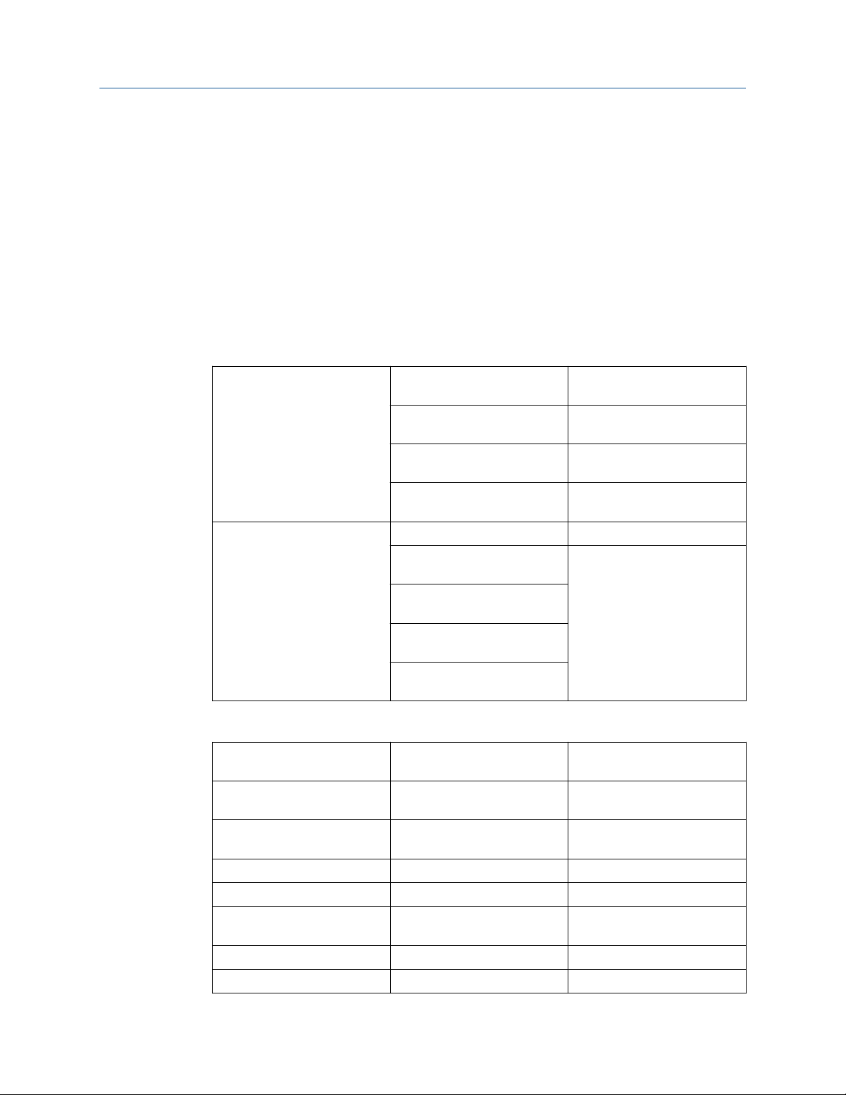
Installation Guide Technical data
MHM-97923-PBF June 2022
9 Technical data
Only specifications with indicated tolerances or limit values are obligatory. Data without
tolerances or without error limits are informative data and not guaranteed. Technology is
under constant development, and specifications are subject to change without notice. If
not otherwise specified, all data refer to a nominal supply voltage of +24 V DC and an
environmental temperature of +23°C .
9.1 Connections and interfaces
Connections
Power connector
Shield connection M6 Outside of the box
Conductor cross section
stranded minimum 0.2 mm
Conductor cross section
stranded maximum 2.5 mm
Conductor cross section AWG
minimum 24
Conductor cross section AWG
maximum12
Conductor cross section
stranded minimum 0.32 mm
Conductor cross section
stranded maximum 2.5 mm
Conductor cross section AWG
minimum 22
Conductor cross section AWG
maximum 14
2
2
13 internal terminals for cable
2
shield connections
2
Interfaces
Ethernet LAN2.1 and LAN2.2
socket
2 x RJ45 shielded
Ethernet LAN2.1 and LAN2.2
data rate
Ethernet LAN2.1 and LAN2.2
cable length
Ethernet EEE supported
Ethernet LAN1 socket RJ45 shielded
Ethernet LAN1 data rate 10/100 Mbit/s / 1 Gbit/s Base T Half and full duplex, with auto-
Ethernet LAN1 cable length up to 100 meters Shielded cable
SD card microSD card holder For future use
MHM-97923-PBF, Rev. 2.5 85
10/100 Mbit/s Base TX Half and full duplex, with auto-
negotiation and Auto-MDI-X
up to 100 meter Shielded cable
negotiation and Auto-MDI-X

Technical data Installation Guide
June 2022 MHM-97923-PBF
9.2 Indications and buttons
Indications
Reset/Recovery indication light LED Blue/Green Assigned to the reset button
Front indication light LED Red/Green
Buttons
Reset/Recovery button Hidden tact switch
9.3 Slots
Internal power module +24 V DC AM 5730
Number of CHARM slots 12
Supported CHARM Terminal
Blocks
Compatible CHARMS RTD KL3031X1-BA1
Address plug Plug 1 Installation requires Address
1
No HART support.
Standard Terminal Block KL4502X1-BA1
Thermocouple Terminal Block KL4502X1-NA1
Relay Terminal Block KL4502X1-MA1
Thermocouple/mV KL3032X1-BA1
AI 4-20 mA (HART1) KL3021X1-BA1
DI 24 V DC Low Side (V DC Dry
Contact)
DO 24 V DC High Side KL3002X1-BA1
VI Piezo CHARM AM 5125
VI Voltage CHARM AM 5620
VI Tach CHARM AM 5312
KL3003X1-BA1
Terminal Block
9.4 Dimensions and electrical data – AMS Asset Monitor
Electrical data
Power dissipation
Overvoltage category 1
86 MHM-97923-PBF, Rev. 2.5
<15 W Exclusive feed through power
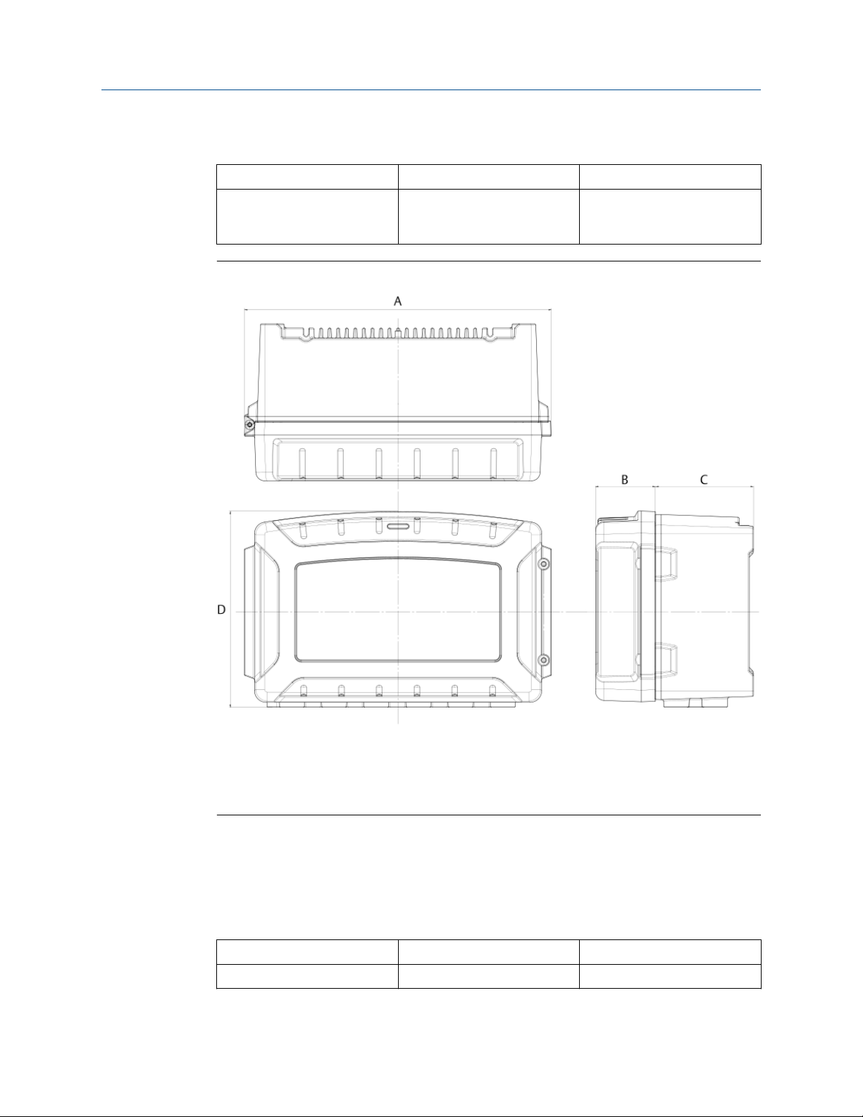
Installation Guide Technical data
MHM-97923-PBF June 2022
Mechanical data
Dimensions see Figure 9-1
Weight <7000 g Without packaging, +24 V DC
Power Module, and all other
installable parts
Figure 9-1: Dimensions
A. 384 mm
B. 75 mm
C. 123 mm
D. 241 mm
9.5 Dimensions and electrical data – +24 V DC Power Module
Electrical data
Input voltage
Reverse polarity protection Continuous
MHM-97923-PBF, Rev. 2.5 87
+24 V DC ± 10%
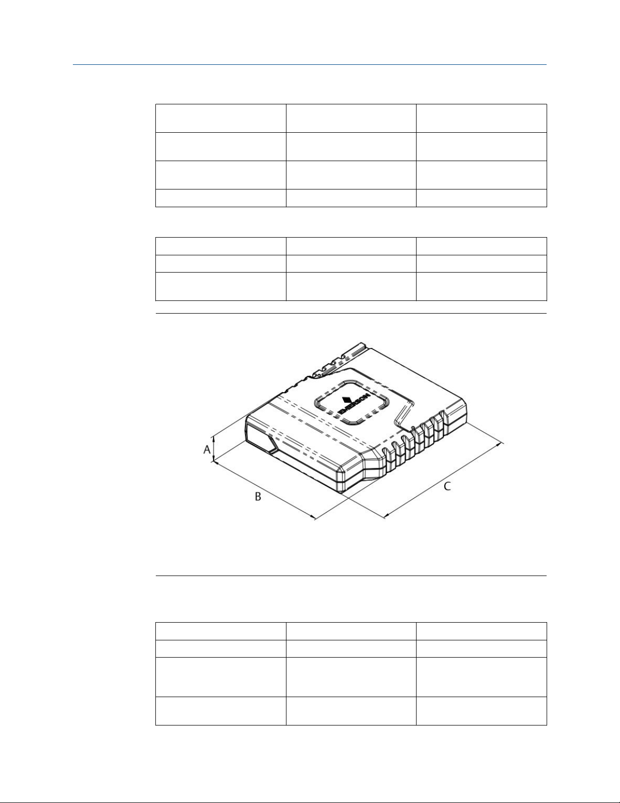
Technical data Installation Guide
June 2022 MHM-97923-PBF
Overvoltage shutdown
threshold
Power requirement 0.88 A at +21.6 V DC Maximum for a fully equipped
Pass through capacity 1.2 A Maximum for additional 12 x
Fuse protection Internal Non-replaceable fuse
+34.3 V DC ± 1.8 V, self-recovering after 9
seconds
AMS Asset Monitor
100 mA per CHARM
Mechanical data
Dimensions see Figure 9-2
Weight <150 g Without packaging
Status indication Green power LED
Red error LED
Figure 9-2: Dimensions
A. 25 mm
B. 95 mm
C. 113 mm
9.6 Environmental conditions – AMS Asset Monitor
Operating temperature -40 to +55°C
Storage temperature -40 to +85°C
Humidity 5 to 95% Relative humidity without
condensation, suitable for
indoor and outdoor use
Protection IP66 and NEMA-4X According to IEC 60529 /
NEMA-250
88 MHM-97923-PBF, Rev. 2.5
Installation Guide Technical data
MHM-97923-PBF June 2022
Shock 150 m/s
Vibration 0.15 mm 10 to 58.1 Hz
20 m/s
Operating altitude <2000 m Above sea level
Allowed degree of pollution 2 Internal. Ensure that no water
2
2
According to IEC 60068-2-27,
4000 shocks per axis
58.1 to 150 Hz
According to IEC 60068-2-6,
floating sinus, 20 cycles, three
axes
or dirt gets into the AMS Asset
Monitor when it is open.
9.7 Environmental conditions – +24 V DC Power Module
Operating temperature -40 to +70°C
Storage temperature -40 to +85°C
Humidity 5 to 95% Relative humidity without
condensation
Shock 150 m/s
2
According to IEC 60068-2-27,
4000 shocks per axis
Vibration 0.15 mm 10 to 58.1 Hz
2
20 m/s
Operating altitude <2000 m Above sea level
58.1 to 150 Hz
According to IEC 60068-2-6,
floating sinus, 20 cycles, three
axes
MHM-97923-PBF, Rev. 2.5 89

Technical data Installation Guide
June 2022 MHM-97923-PBF
90 MHM-97923-PBF, Rev. 2.5

Installation Guide Certificates
MHM-97923-PBF June 2022
10 Certificates
MHM-97923-PBF, Rev. 2.5 91

Certificates Installation Guide
June 2022 MHM-97923-PBF
92 MHM-97923-PBF, Rev. 2.5

Installation Guide
MHM-97923-PBF June 2022
MHM-97923-PBF, Rev. 2.5 93

MHM-97923-PBF
Rev. 2.5
2022
Emerson
12001 Technology Drive
Eden Prairie, MN 55344 USA
T 1(952)828-3000
www.Emerson.com
Emerson
835 Innovation Drive
Knoxville, TN 37932 USA
T +1 865-675-2400
F +1 865-218-1401
www.Emerson.com
©
2022, Emerson. All rights reserved.
The contents of this publication are presented for informational purposes only, and while diligent
efforts were made to ensure their accuracy, they are not to be construed as warranties or
guarantees, express or implied, regarding the products or services described herein or their use or
applicability. All sales are governed by our terms and conditions, which are available on request. We
reserve the right to modify or improve the designs or specifications of our products at any time
without notice.
The Emerson logo is a trademark and service mark of Emerson Electric Co. The AMS logo is a mark of
one of the Emerson family of companies. All other marks are the property of their respective owners.
Emerson
Jöbkesweg 3
48599 Gronau
Germany
T +49 2562 709 0
F +49 2562 709 401
www.Emerson.com/ams
 Loading...