


AMS Asset Monitor
Online Prediction, Protection, and Process Monitor
Operating Manual
MHM-97924-PBF, Rev 3.2
June 2022

Copyright
©
2022 by Emerson. All rights reserved.
No part of this publication may be reproduced, transmitted, transcribed, stored in a retrieval system, or translated into any
language in any form by any means without the written permission of Emerson.
Disclaimer
This manual is provided for informational purposes. EMERSON MAKES NO WARRANTY OF ANY KIND WITH REGARD TO THIS
MATERIAL, INCLUDING, BUT NOT LIMITED TO, THE IMPLIED WARRANTIES OF MERCHANTABILITY AND FITNESS FOR A PARTICULAR
PURPOSE. Emerson shall not be liable for errors, omissions, or inconsistencies that may be contained herein or for incidental or
consequential damages in connection with the furnishing, performance, or use of this material. Information in this document is
subject to change without notice and does not represent a commitment on the part of Emerson. The information in this manual is
not all-inclusive and cannot cover all unique situations.
Patents
The product(s) described in this manual are covered under existing and pending patents.
Vermerk zur Installation der Messketten in explosionsgefährdeter Umgebung.
Soll die Messkette in explosionsgefährdeter Umgebung installiert werden, so ist auf die Einhaltung der in der
Gebrauchsanweisung enthaltenen Installationshinweise zu achten. Sollten dabei sprachliche Schwierigkeiten
auftreten, wenden Sie sich bitte an die Herstellerfirma, sie wird Ihnen eine Übersetzung der relevanten Artikel in der
Landessprache des Verwendungslandes zukommen lassen.
Nota fuq l−installazzjoni tal−ktajjen tal−kejl f’ambjent esplożiv
Jekk il−katina tal−kejl suppost li tigi installata f’ambjent esplożiv, hu importanti li ssegwi l−istruzzjonijiet pertinenti
tal−manwal.Jekk issib xi diffikultà bil−lingwa, jekk joghgbok ikkuntattja lill−manifattur biex tikseb traduzz-joni tal
−paragrafi rilevanti fil−lingwa mehtiega.
Anmärkning beträffande installation av mätkedjorna i explosionsfarlig miljö.
Ska mätkedjan installeras i explosionsfarlig miljö, måste de anvisningar följas som ges i instruktionsboken
beträffande installationen. Skulle därvid språkproblem uppstå, ber vi dig kontakta det tillverkande företaget som
då kommer att sända dig en översättning av de relevanta artiklarna på användningslandets språk.
Opomba za namestitev merilne verige v eksplozivno ogroženem okolju
Èe se merilna veriga namešèa v eksplozivno ogroženem okolju, je potrebno upoštevati namestitvena opozorila, ki
so v Navodilih za uporabo. Èe se pri tem pojavijo jezikovne težave, se posvetujte z izdelovalcem; poslali vam bodo
prevod ustreznih èlankov v jeziku države, kjer se naprava uporablja.
Záznam k inštalácii meracích reťazcov vo výbušnom prostredí
Ak má byť merací reťazec inštalovaný vo výbušnom prostredí, treba dbať na dodržiavanie pokynov k inštalácii,
uvedených v návode na použitie. V prípade, že by sa pritom vyskytli jazykové problémy, obráťte sa prosím na
výrobcu, ktorý Vám zašle preklad relevantných èlánkov v jazyku Vašej krajiny.
Nota referente à instalação de cadeias de agrimensor em ambientes potencialmente explosivos
Caso a cadeia de agrimensor deva ser instalada em um ambiente potencialmente explosivo, é imprescindível
observar e cumprir as indicações de instalação das instruções de serviço. Caso tenha dificuldades idiomáticas,
queira entrar em contato com a firma produtora, esta poderá enviar−lhe uma tradução dos capítulos mais
importantes no idioma do país onde o produto deverá ser empregado.
Wskazówka dotycząca instalacji łańcuchów mierniczych w otoczeniach zagrożonych eksplozją.
Jeżeli łańcuch mierniczy ma być zainstalowany w otoczeniu zagrożonym eksplozją, należy uwzględnić wskazówki
dotyczące instalacji, które są zawarte w instrukcji obsługi. Jeżeli w trakcie lektury wystąpią jakiekolwiek problemy
związane ze zrozumieniem tekstu, prosimy zwrócić się do producenta, który chętnie wykona tłumaczenie
wybranych części dokumentacji na język danego kraju.
2

Opmerking m.b.t. installatie van elektrische meet circuits in explosiegevaarlijke omgeving
Dient de installatie van elektrische meet circuits in een explosiegevaarlijke omgeving te geschieden, moet men
toezien dat de in de gebruikshandleiding opgenomen installatieinstructies worden nageleefd. Bij taalkundige
problemen gelieve contact op te nemen met de fabrikant, deze zal u vervolgens een vertaling in de taal van het
gebruiksland doen toekomen.
Pastaba dėl matavimo grandinės įrengimo sprogimo atžvilgiu pavojingoje aplinkoje
Jei matavimo grandinė turi būti įrengta sprogimo atžvilgiu pavojingoje aplinkoje, privaloma laikytis vartotojo
instrukcijoje pateiktų įrengimo nurodymų. Jei kiltų sunkumų dėl kalbos, prašome kreiptis į gamintojo įmonę, kuri
pateiks Jums reikiamo skyriaus vertimą į vartotojo valstybės kalbą.
Nota sull’installazione delle catene per misurazione in ambienti a rischio di esplosioni
Nel caso in cui si debbano installare le catene per misurazione in ambienti a rischio di esplosioni, è necessario
attenersi alle avvertenze per l’installazione contenute nelle istruzioni d’uso. Per difficoltà di carattere linguistico,
rivolgetevi alla ditta produttrice. Quest’ultima Vi farà pervenire una traduzione degli articoli rilevanti nella lingua
del paese d’impiego.
Megjegyzės a mėrőláncok robbanásveszėlyes környezetben törtėnő szerelėsėhez.
Ha a mėrőláncot robbanásveszėlyes környezetben kell felszerelni, akkor ügyeljen a Használati útmutatóban közölt
szerelėsi utasítások betartására. Amennyiben nyelvi nehėzsėgek merülnek fel, szíveskedjen a gyártó céghez
fordulni, amely elküldni Önnek a felhasználó ország nyelvėre lefordított, erre vonatkozó cikket.
Remarque concernant l’installation des chaînes de mesure dans un environnement présentant un risque
d’explosion
Si la chaîne de mesure doit être installée dans un environnement présentant un risque d’explosion, il est impératif
de veiller à respecter les consignes d’installation contenues dans les instructions de service. S’il devait ce faisant
surgir des problèmes linguistiques, veuillez vous adresser à la société fabricante: elle vous fera parvenir une
traduction des articles significatifs dans la langue du pays de mise en oeuvre.
Huomautus mittausketjun asentamisesta räjähdysalttiissa ympäristössä
Jos mittausketju tulee asentaa räjähdysalttiissa ympäristössä, on käyttöohjeessa annettuja asennusohjeita
noudatettava. Jos käyttöohjeessa käytetty kieli aiheuttaa ongelmia, kääntykää valmistajayrityksen puoleen. Se
toimittaa käyttöönne tarvittavat artikkelit käyttömaan vir alliselle kielelle käännettynä.
Juhend mõõdukettide ülespanemiseks plahvatusohtlikus piirkonnas.
Kui panna üles mõõdukettid plahvatusohtlikkus piirkonnas, nii tuleb jälgida kasutusjuhendis sisaldatud
instalationimärkmeid. Juhul kui tekkivad raskused keelega, siis pöörduge palun tootja poole. Tootja saadab
emakeelse tõlge vastavalt artiklile ning maale.
Notas sobre la instalación de cadenas de medición en un entorno potencialmente explosivo.
Si ha de instalar la cadena de medición en un entorno potencialmente explosivo, deberá respetar las indicaciones
sobre la instalación, contenidas en el manual de uso. Si surgieran dificultades lingüísticas, póngase en contacto con
la empresa fabricante, que le facilitará una traducción del artículo en la lengua del país donde se emplee.
Note on the installation of the measuring chains in an explosive environment
If the measuring chain is supposed to be installed in an explosive environment, it is important to follow the
pertinent installation instructions in the manual. Should you encounter difficulties with the language, please
contact the manufacturer to obtain a translation of the relevant paragraphs into the language required.
3

Σημεíωση για τηυ εγκατáσταση αλuσíδωυ μέτρησης σε περιβáλλου, στο oπoío uπàρΧει κíυδuυoς έκρηξης
Εáυ η αλuσυδα μέτρησης πρóκειται υα εγκατασταΘεí σε περιβáλλoυ, στo oπoío uπáρΧει κíυδuυoς έκρηξης, πρέπει
υα τηρηΘoúυ oπωσδńπoτε oι oδηγíες εγκατáστασης πoυ περιλαμβáυoυται στις oδηγíες Χρńσης. Εáυ υπáρξouυ
γλωσσικές δuσκoλíες καταυóησης, παρακαλoúμε υα απεuΘuυΘεíτε στηυ κατασκεuáστρια εταιρεíα, η oπoíα Θα
ϕρoυτíσει για τηυ απoστoλń μιας μετáϕρασης τωυ σΧετικωυ áρΘρωυ στη γλωσσα της Χωρας Χρńσης.
Info vedrørende installation af målekæderne i eksplosionstruede omgivelser
Hvis målekæden skal installeres i eksplosionstruede omgivelser, skal installationsanvisningerne i brugsanvisningen
følges. Hvis der i denne forbindelse opstår sproglige problemer, bedes De henvende Dem til produktionsfirmaet,
som så vil sørge for, at De modtager en oversætelse af den relevante artikel på Deres sprog.
Poznámka k instalaci mĕřicích řetězců v prostředí s nebezpečím výbuchu.
Když má být měřicí řetězec (sestávající z čidla a konvertoru) instalován v prostŕedí s nebezpečím výbuchu, tak je
třeba respektovat instalační pokyny, které jsou součástí návodu k upotřebení. Kdyby při tom došlo k jazykovým
potížím, tak prosíme kontaktujte výrobní firmu, která Vám relevantní článek zašle v jazyku krajiny použití.
Piezīme par mērīšanas ķēžu instalēšanu sprādziena bīstamās zonās.
Ja mērīšanas ķēde jāuzstāda sprādzienbīstamā zonâ, ir jāievēro lietošanas instrukcijā dotie instalēšanas norādījumi.
Ja rodas kādas valodas grūtības, lūdzu griezieties pie izgatavotāja firmas, kas Jums nosūtīs nozīmīgâko nodaļu
tulkojumus lietotāja valsts valodā.
Emerson
epro GmbH
Jöbkesweg 3
48599 Gronau
Germany
T +49 2562 709 0
F +49 2562 709 401
www.Emerson.com
4

Operating Manual Contents
MHM-97924-PBF June 2022
Contents
Chapter 1 General.......................................................................................................................... 9
1.1 About this manual............................................................................................................................ 9
1.2 Symbols............................................................................................................................................9
1.3 Liability and guarantee................................................................................................................... 10
1.4 Technical support...........................................................................................................................10
1.5 Storage and transport.....................................................................................................................10
1.6 Disposal of the device.....................................................................................................................11
1.7 China RoHS Compliance................................................................................................................. 11
1.8 Installation awareness.................................................................................................................... 11
Chapter 2 Safety instructions....................................................................................................... 13
2.1 Using the device............................................................................................................................. 13
2.2 Owner's responsibility.....................................................................................................................13
2.3 Radio interference.......................................................................................................................... 13
2.4 ESD safety...................................................................................................................................... 14
2.5 Important information about hazardous voltages.......................................................................... 14
Chapter 3 Functional overview.....................................................................................................15
3.1 Implemented rules......................................................................................................................... 17
3.2 External interfaces..........................................................................................................................20
3.3 Notification system........................................................................................................................ 20
3.4 Health calculation...........................................................................................................................28
3.5 Trend data storage......................................................................................................................... 29
3.6 Basic protection..............................................................................................................................30
3.7 Predicates and data collections.......................................................................................................30
Chapter 4 First steps.................................................................................................................... 33
4.1 Requirements on the configuration device..................................................................................... 33
4.2 Connect to the AMS Asset Monitor................................................................................................. 33
4.3 Log out from AMS Asset Monitor Web Interface............................................................................. 35
4.4 Overview web interface.................................................................................................................. 35
4.5 Enter basic settings.........................................................................................................................37
4.5.1 Basics.......................................................................................................................................... 38
4.5.2 Network IPv4...............................................................................................................................39
4.5.3 DNS.............................................................................................................................................40
4.5.4 Date and time..............................................................................................................................41
Chapter 5 Data and network security........................................................................................... 43
5.1 Certificates.....................................................................................................................................43
5.2 Firewall considerations................................................................................................................... 43
5.3 Additional security considerations..................................................................................................44
MHM-97924-PBF, Rev. 3.2 v

Contents Operating Manual
June 2022 MHM-97924-PBF
Chapter 6 Configure the AMS Asset Monitor.................................................................................45
6.1 Configuration page overview..........................................................................................................46
6.2 CHARMs......................................................................................................................................... 48
6.2.1 Recomended procedures – CHARMs........................................................................................... 48
6.2.2 Parameter description – CHARMs................................................................................................50
6.3 External data points........................................................................................................................78
6.3.1 Recommended procedures – External data points.......................................................................78
6.3.2 Parameter description – External data points.............................................................................. 80
6.4 Predicates.......................................................................................................................................81
6.4.1 Recommended procedures – Predicates..................................................................................... 81
6.4.2 Parameter description – Predicates............................................................................................. 82
6.5 Assets.............................................................................................................................................83
6.5.1 General........................................................................................................................................83
6.5.2 Fan – axial, direct motor drive......................................................................................................85
6.5.3 Fan – axial, gearbox drive.............................................................................................................88
6.5.4 Fan – centrifugal, center hung..................................................................................................... 91
6.5.5 Fan – centrifugal, over hung........................................................................................................ 93
6.5.6 Gearbox – single reduction..........................................................................................................96
6.5.7 Generic – rotating, center hung...................................................................................................99
6.5.8 Generic – rotating, over hung....................................................................................................102
6.5.9 Heat exchanger – shell & tube, counter-current.........................................................................105
6.5.10 Hydrocarbon pump – centrifugal, overhung............................................................................106
6.5.11 Motor – inductive....................................................................................................................109
6.5.12 Pump – centrifugal, center hung............................................................................................. 111
6.5.13 Pump – centrifugal, over hung................................................................................................ 114
6.5.14 Recommended procedure – Assets......................................................................................... 116
6.5.15 Parameter description – Assets............................................................................................... 118
6.5.16 Tachometer.............................................................................................................................129
6.5.17 Export asset specific information as MTP file............................................................................130
6.6 Output logics................................................................................................................................131
6.6.1 Recommended procedures – Output logics.............................................................................. 131
6.6.2 Parameter description – Output Logics..................................................................................... 133
6.7 Data collections............................................................................................................................136
6.7.1 Recommended procedures – Data collections...........................................................................137
6.7.2 Parameter description – Data collections.................................................................................. 138
6.8 Users............................................................................................................................................ 143
6.8.1 Recommended procedures – Users........................................................................................... 143
6.8.2 Parameter description...............................................................................................................144
6.8.3 User menu.................................................................................................................................146
6.9 System......................................................................................................................................... 147
6.9.1 Recommended procedures – System........................................................................................ 147
vi MHM-97924-PBF, Rev. 3.2

Operating Manual Contents
MHM-97924-PBF June 2022
6.9.2 Parameter description – System................................................................................................147
Chapter 7 Commission the AMS Asset Monitor...........................................................................163
Chapter 8 Status and health indication.......................................................................................165
8.1 Dashboard....................................................................................................................................165
8.2 Status overview – CHARM............................................................................................................ 166
8.2.1 Measurement displays...............................................................................................................168
8.3 Status overview – asset................................................................................................................ 172
8.3.1 Health displays.......................................................................................................................... 174
8.4 Status overview – system .............................................................................................................176
8.5 Alerts............................................................................................................................................180
8.6 Alerts – asset................................................................................................................................ 181
8.7 Alerts – CHARM............................................................................................................................ 182
8.8 Tiles view and list view..................................................................................................................183
8.8.1 Tiles view – CHARMs..................................................................................................................183
8.8.2 List view – CHARMs................................................................................................................... 185
8.8.3 Tiles view – External data points................................................................................................ 186
8.8.4 List view – External data points.................................................................................................. 187
8.8.5 Tiles view – Predicates...............................................................................................................188
8.8.6 List view – Predicates.................................................................................................................188
8.8.7 Tiles view – Assets..................................................................................................................... 189
8.8.8 List view – Assets....................................................................................................................... 189
8.8.9 Tiles view – Output logics.......................................................................................................... 190
8.8.10 List view – Output logics..........................................................................................................190
8.8.11 Tiles view – Data collections.................................................................................................... 191
8.8.12 List view – Data collections......................................................................................................191
Chapter 9 Maintenance..............................................................................................................193
9.1 Firmware update.......................................................................................................................... 193
9.1.1 Firmware update – AMS Asset Monitor......................................................................................193
9.1.2 Firmware update – CHARM....................................................................................................... 194
9.2 Reset button................................................................................................................................ 195
9.2.1 Recovery mode......................................................................................................................... 196
9.2.2 Activate bypass IP address.........................................................................................................199
9.2.3 Reset to factory default............................................................................................................. 200
9.3 Reboot......................................................................................................................................... 200
9.4 Backup and restore.......................................................................................................................201
9.4.1 Backup...................................................................................................................................... 202
9.4.2 Restore......................................................................................................................................202
Index .................................................................................................................................. 205
MHM-97924-PBF, Rev. 3.2 vii

Contents Operating Manual
June 2022 MHM-97924-PBF
viii MHM-97924-PBF, Rev. 3.2

Operating Manual
MHM-97924-PBF June 2022
General
1 General
1.1 About this manual
This manual contains information and step-by-step instructions for configuring and
operating the AMS Asset Monitor.
Read this manual completely prior to starting installation of the device. Comply with all
safety instructions.
This operating manual applies for AMS Asset Monitors with a hardware revision and
firmware version listed in Table 1-1. See type plate for hardware revision level. The
firmware version is displayed in the status overview of the system (see Status overview –
system).
Table 1-1: Hardware revision and firmware version
Component Hardware revision Firmware version
AMS Asset Monitor 13 and later 2.1.1
Include the operating manual when transferring the device to third parties.
Note
When requesting technical support, indicate type and serial number from the type plate.
See Table 1-2 for a list of documents referred to in this operating manual.
Table 1-2: Referenced documents
MHM Number Document name
MHM-97925-PBF Installation Guide VI Piezo CHARM
MHM-97929-PBF Installation Guide VI Voltage CHARM
MHM-97930-PBF Installation Guide VI Tach CHARM
MHM-97923-PBF Installation Guide AMS Asset Monitor
AMS-SEC-PSG-001 AMS Product Security Documentation
--- User Guide AMS Machine Works
1.2 Symbols
Note
This symbol marks passages that contain important information.
CAUTION
This symbol marks operations that can lead to malfunctions or faulty measurements, but
will not damage the device.
MHM-97924-PBF, Rev. 3.2 9

General
June 2022 MHM-97924-PBF
Operating Manual
DANGER
A danger indicates actions that can lead to property damage or personal injury.
1.3 Liability and guarantee
Emerson is not liable for damages that occur due to improper use. Proper use also includes
the knowledge of, and compliance with, this document.
Customer changes to the device that have not been expressly approved by Emerson will
result in the loss of guarantee.
Due to continuous research and further development, Emerson reserves the right to
change technical specifications without notice.
1.4 Technical support
You may need to ship this product for return, replacement, or repair to an Emerson
Product Service Center. Before shipping this product, contact Emerson Product Support to
obtain a Return Materials Authorization (RMA) number and receive additional instructions.
Product Support
Emerson provides a variety of ways to reach your Product Support team to get the answers
you need when you need them:
Phone
Email
Web
To search for documentation, visit http://www.emerson.com.
To view toll free numbers for specific countries, visit http://www.emersonprocess.com/
technicalsupport.
Note
If the equipment has been exposed to a hazardous substance, a Material Safety Data Sheet
(MSDS) must be included with the returned materials. An MSDS is required by law to be
available to people exposed to specific hazardous substances.
Toll free 800.833.8314 (U.S. and Canada)
+1.512.832.3774 (Latin America)
+63.2702.1111 (Asia Pacific, Europe, and Middle East)
Guardian.GSC@Emerson.com
http://www.emerson.com/en-us/contact-us
1.5 Storage and transport
Store and transport the device only in its original packaging. Technical data specifies the
environmental conditions for storage and support.
10 MHM-97924-PBF, Rev. 3.2

Operating Manual
MHM-97924-PBF June 2022
General
1.6 Disposal of the device
Provided that no repurchase or disposal agreement exists, recycle the following
components at appropriate facilities:
• Recyclable metal
• Plastic elements
Sort the remaining components for disposal, based on their condition. National laws or
provisions on waste disposal and protection of the environment apply.
Note
Environmental hazards! Electrical waste and electronic components are subject to
treatment as special waste and may only be disposed by approved specialized companies.
1.7 China RoHS Compliance
Our products manufactured later than June 30, 2016 and those which are sold in the
People's Republic of China are marked with one of the following two logos to indicate the
Environmental Friendly Use Period in which it can be used safely under normal operating
conditions.
Products without below mentioned marking are either manufactured before June 30 or
are non-electrical equipment products (EEP).
Circling arrow symbol with "e": The product contains no hazardous substances over
the Maximum Concentration Value and it has an indefinite Environmental Friendly
Use Period.
Circling arrow symbol with a number: This product contains certain hazardous
substances over the Maximum Concentration Value and it can be used safely under
normal operating conditions for the number of years indicated in the symbol. The
names and contents of hazardous substances can be found in the folder "China
RoHS Compliance Certificates" on the documentation CD or DVD enclosed with the
product.
1.8 Installation awareness
Note
When planning a measurement, observe the following items:
• Consider environmental conditions which might have an influence on the
measurement such as temperature, humidity, substances aggressive to the sensor,
and pollution.
• Always use a stiff and vibration-free sensor holder.
• Define a suitable measuring range, not larger than necessary, in consultation with the
operator of the plant.
• Define the trip limit in consultation with the operator of the plant.
MHM-97924-PBF, Rev. 3.2 11

General Operating Manual
June 2022 MHM-97924-PBF
• Take measurement deviations into account when defining the trip limit.
• Use a sensor that meets the requirements of the defined measuring range.
• Ensure an EMC-compatible installation including the use of proper cables.
• Ensure proper function of the measurement before activating the measurement for
regular operation.
12 MHM-97924-PBF, Rev. 3.2

Operating Manual Safety instructions
MHM-97924-PBF June 2022
2 Safety instructions
To ensure safe operation, carefully observe all instructions in this manual.
The correct and safe use of this device requires that operating and service personnel both
understand and comply with general safety guidelines and observe the special safety
comments listed in this manual. Where necessary, safety-sensitive points on the device
are marked.
DANGER
Because the device is electrical equipment, commissioning and service must be performed
only by trained and authorized personnel. Maintenance must be carried out only by
trained, specialized, and experienced personnel.
2.1 Using the device
Install and use the device as specified in this document.
If the device is used in a manner not specified by the manufacturer, the functions and
protection provided by the device may be impaired.
2.2 Owner's responsibility
If there is a reason to suspect that hazard-free operation, and thus, adequate machine
protection is no longer possible, take the device out of operation and safeguard it from
unintentional operation. This is the case:
• if the device shows visible damage.
• if the device no longer works.
• after any kind of overload that has exceeded the permissible limits (such as those
detailed in chapter "Technical data," section "Environmental conditions").
DANGER
If device tests have to be completed during operation or if the device has to be replaced or
decommissioned, it will impair the machine protection and may cause the machine to
shut down. Make sure to deactivate machine protection before starting such work, and
reactivate it after work has been completed.
2.3 Radio interference
The device is carefully shielded and tested to be technically immune to radio interference
and complies with current standards. However, if you operate this device together with
other peripheral devices that are not properly shielded against radio interference,
disturbances and radio interferences may occur.
MHM-97924-PBF, Rev. 3.2 13

Safety instructions Operating Manual
June 2022 MHM-97924-PBF
2.4 ESD safety
DANGER
Internal components can be damaged or destroyed due to electrostatic discharge (ESD)
during the handling of the device.
Take suitable precautions before handling the device to prevent electrostatic discharges
through the sensor electronics. Such measures might include, for example, wearing an
ESD bracelet. Transport and storage of electronic components may only be made in ESDsafe packaging.
Handle the device with particular care during dry meteorological conditions with relative
humidity below 30% as electrostatic discharges can appear more frequently.
2.5 Important information about hazardous voltages
DANGER
The KL4502X1-MA1 CHARM Relay Output Terminal Block may have hazardous live
voltages on its output terminals. This terminal block is capable to switch field power of 250
V AC. Ensure that proper safety precautions, such as de-energizing field power, are
observed during installation, maintenance, or any time wiring changes are made to the
CHARM Relay Output Terminal Block.
14 MHM-97924-PBF, Rev. 3.2

Operating Manual Functional overview
MHM-97924-PBF June 2022
3 Functional overview
The AMS Asset Monitor is a field mountable device to collect data from driven and none
driven assets (see Table 3-1) by using different kinds of sensor such as piezoelectric
vibration sensors to analyze the machine health and to provide alarms depending on the
machine state. The hardware is designed to carry up to 12 CHARMs1 – AM 5125 VI Piezo
CHARMs, VI Tach CHARMs, VI Voltage CHARMs, and compatible DeltaV™ CHARMs – to
connect input and output signals. See AMS Asset Monitor Installation Guide for further
details on the hardware.
The AMS Asset Monitor can be used as a standalone prediction device with basic
protection functions or integrated into a network and connected to subsequent systems
such as Emerson's AMS Machine Works or AMS Plantweb Optics.
The installation of additional software on your PC or Laptop is not necessary. Use your web
browser to configure and control the AMS Asset Monitor.
The input signals measured by sensors mounted on the equipment to be monitored are
connected through sensor specific CHARMs to the signal processing parts of the AMS
Asset Monitor. The preprocessed sensor signals are forwarded to the prediction unit for
analysis based on predefined rules with configurable parameters. The prediction results
are output based on selectable logics through output CHARMs or forwarded to
subsequent systems through the Ethernet interface. The input sensor signals are also
forwarded to the unit for basic protection. The typical reaction time of the basic protection
is < 1 second. Detected alarms are output through output CHARMs.
The AMS Asset Monitor has a data collection function to send specific waveform data to
AMS Machine Works.
CHAR
1
MHM-97924-PBF, Rev. 3.2 15
acterizing Module

Functional overview Operating Manual
June 2022 MHM-97924-PBF
Figure 3-1: Functional overview
A. AMS Asset Monitor
B. Prediction and logic unit
C. Signal preprocessing
D. Basic protection unit
E. Signal input CHARMs and output CHARMs (available input signals depend on installed
CHARMs) and Ethernet interface for data exchange through Modbus over TCP/IP, OPC
UA, and configuration
F. Equipment to be monitored (see Table 3-1)
G. Configuration PC, Server, etc.
H. Control cabinet of the Equipment
Table 3-1: Supported assets
Driver Intermediate Driven Non-driven
Electric motor Gear box Pump Center
hung
Over hung
Fan Center
hung
Over hung
Axial
Heat exchanger – shell
& tube, countercurrent
16 MHM-97924-PBF, Rev. 3.2

Operating Manual Functional overview
MHM-97924-PBF June 2022
3.1 Implemented rules
The AMS Asset Monitor has several functions such as FFT, Energy in Bands, or
PeakVue Plus™ for analyzing the collected machine data. Predefined rules with
configurable parameters are used to evaluate the machine's health based on the used
prediction functions. The rules identify the running speed amplitude using data from a
tachometer, a DeltaV DI CHARM, from an AI CHARM, from the VI Tach CHARM, from an
external data point, or from a manual input.
The following spectrum-based analytics are implemented into the AMS Asset Monitor:
Alignment
Figure 3-2: Spectrum
Bearing
Figure 3-3: Fault frequencies bearing
The alignment rule looks at the running speed and two times running speed
amplitude relationship. From this relationship the alignment rule
determines if there is a likely alignment issue. The rule can be executed at
bearing and shaft vibration measurements.
The bearing rule uses the PeakVue Plus™ algorithm to recognize repetitive and
non-synchronous events in the frequency spectrum to detect mechanical
bearing defects. With known individual mechanical bearing parameters or fault
frequencies (FTF, BSF, BPFO, BPFI) fundamental bearing defects can be
detected.
A. FTF (Fundamental train frequency)
B. BSF (Ball spin frequency)
C. BPFO (Ball pass frequency outer)
D. BPFI (Ball pass frequency inner)
Balance
MHM-97924-PBF, Rev. 3.2 17
The balance rule looks at the asset running speed amplitude to perform its
analysis (see Figure 3-2). The rule determines if the one times running speed
amplitude is higher than the selected acceptable balance level.

Functional overview Operating Manual
June 2022 MHM-97924-PBF
Blade
pass
Typically, the blade pass rule is a blade or vane pass assessment. The blade
pass rule looks at the one times and two times pass frequency amplitude for
excessive pulsation levels. High amplitudes indicate flow restrictions,
impeller clearance problems, and possible resonance problems. There are no
general industry standards for the allowable pass amplitude, so the alert
limits for this will rely on the vendor of the equipment or customer
determined allowable levels.
Figure 3-4: Velocity spectrum – blade pass
A. Amplitude 1
B. Blade pass 1
C. Amplitude 2
D. Blade pass 2
Flow turbulence – pump
Fluid turbulence analysis. The flow rule looks for cavitation,
aeration, or recirculation in pumps.
Flow turbulence – fan
Gas turbulence analysis. The flow rule looks for rotating stall
or surge in fans.
Figure 3-5: Velocity spectrum – flow
Uneven air gap
Inductive motor analysis. The uneven air gap rule uses the second
harmonic amplitude of the line frequency to determine if an
inductive motor has an air gap problem caused by a soft foot, an
eccentric or deformed stator, or an eccentric rotor.
Gear
misalignment
The gear misalignment rule looks at the one times, two times, and
three times gear mesh frequencies amplitude to determine if there
is a gear alignment issue.
18 MHM-97924-PBF, Rev. 3.2

Operating Manual Functional overview
MHM-97924-PBF June 2022
Tooth wear
The tooth wear rule looks at the energy of the sidebands of the one
times, two times, and three times gear mesh frequencies to determine
if there is an issue with a wear down tooth.
Cracked or
broken tooth
This evaluation is under development. The cracked or broken tooth rule
uses the PeakVue Plus™ algorithm to detect possible mechanical
gearbox faults.
Figure 3-6: Velocity spectrum – example for gear mesh frequency with sidebands
A. Gear mesh amplitude
B. Gear mesh frequency
Looseness
The looseness rule looks at the ratio of tree times to one times running
speed amplitude to determine if looseness is present (see Figure 3-2). The
four times running speed amplitude is automatically used for the
determination if a fan with three blades is supervised.
Lubrication
The lubrication rule uses the PeakVue Plus™ algorithm to determine if there
is an under or over lubrication issues with an antifriction bearing.
Oil whirl
The oil whirl rule looks for bearing instability issues at sleeve bearings
caused by oil whirls. The 0.3X to 0.55X amplitudes are supervised to detect
oil whirl problems.
Figure 3-7: Spectrum – oil whirl
Fouling
The fouling rule detects a decreased heat transfer coefficient because of
deposits in the heat exchanger by checking process values such as flow and
temperature.
Duty
The duty rule checks the heat duty on the cold and hot side of the heat
exchanger to survey the quality of the flow and temperature measurements
used for the fouling detection. The fouling detection can be imprecise if the
heat duty on the cold and hot side is uneven.
MHM-97924-PBF, Rev. 3.2 19

Functional overview Operating Manual
June 2022 MHM-97924-PBF
An integrated bearing database with fault frequencies and mechanical parameters of
typically used types of antifriction bearing supports the asset health supervision.
3.2 External interfaces
The AMS Asset Monitor is equipped with several interfaces such as OPC UA, Modbus TCP,
Plantweb Optics Data Collector, and AMS Machine Works to provide data to subsequent
systems.
Import external data such as temperature or pressure through the OPC UA or Modbus TCP
interface into the AMS Asset Monitor by using external data points (see External data
points).
OPC UA
The integrated OPC UA (Open Platform Communications United Architecture) server is
capable to provide data simultaneously to five OPC UA clients. Up to 1000 OPC items (data
points) per connection can be read at a minimum cycle time of one second. See OPC UA.
Modbus TCP
The integrated Modbus server is capable to provide data simultaneously to up to five
Modbus TCP clients. Writing data to the AMS Asset Monitor is also supported. Assign
internal values to the Modbus registers to get a user defined Modbus table. See Modbus
TCP.
Plantweb Optics Data Collector
The Plantweb Optics Data Collector is specially designed to provide data to Emerson's
Plantweb Optics. Create a Plantweb Optics Data Collector user to use this interface with
Plantweb Optics. See Parameter description and Plantweb Optics Data Collector Interface.
AMS Machine Works
The Machine Works interface is designed to provide data to Emerson's AMS Machine
Works by using the data collection function, see Data collections. Create an AMS Machine
Works user to use this interface with AMS Machine Works. See Parameter description and
AMS Machine Works interface.
3.3 Notification system
Standardized elements such as a color system, different alert levels and texts help to
distinguish the importance level of notifications.
Meaning of the general colors
Buttons and notifications are colored depending on their functions and meanings.
Table 3-2: General color meaning
Color Meaning
Blue Information, Maintenance
Green OK
20 MHM-97924-PBF, Rev. 3.2

Operating Manual Functional overview
MHM-97924-PBF June 2022
Table 3-2: General color meaning
Color Meaning
Yellow Advise
Orange Warning
Red Critical
Gray Unknown
Purple Unconfigured
(continued)
Messages in the notification area
Detected events that reduce the health status of assets or CHARMs are indicated by
messages which appear in the notification area2. The background color of the message
depends on the alert level.
Figure 3-8: Structure of the message
A. Colored status bar
B. Name of the analysis function that has detected the event
C. Calculated health value in percent, alert level, and indication how long the event is
already present.
D. Description of the detected health event including a recommendation on how to solve it.
E. Time stamp of the event
F. Measurement locations with health indication used for the rule. The measurement
location with the lowest health indication provides the overall alert in the rule.
Measurement locations without a value ( ---%) are not available for the rules calculation.
G. Button for opening or closing the measurement location information
Alert levels
There are three alert levels to indicate the health of the supervised assets and the health of
the AMS Asset Monitor.
2
See Status overview – CHARM and Status overview – asset.
MHM-97924-PBF, Rev. 3.2 21

Functional overview Operating Manual
June 2022 MHM-97924-PBF
Table 3-3: Alert levels
1
Level
Hi or Lo Advise
HiHi or LoLo Warning
HiHiHi or LoLoLo Critical (Danger)
1
Output logics
Health level Color
OK
AMS Asset Monitor status in browser tab name
The system status of the AMS Asset Monitor is indicated with a colored dot in the browser
tab.
Figure 3-9: Status in browser tab
A. Status indication
See Table 3-2 for color explanation.
Status light of the AMS Asset Monitor
The most important notifications are also indicated by a bicolored status light at the front
of the AMS Asset Monitor.
Table 3-4: Status light of the AMS Asset Monitor
Event Status light Recommendation
Color Blinking
pattern
No fault detected Green Solid ---
Health value is good (≥ 90%) ---
Configuration required Green Fast flashing (1
per 500
milliseconds
seconds)
Maintenance mode1 is active Open AMS Asset Monitor Web
Open AMS Asset Monitor Web
Interface to check the
configuration on
inconsistencies.
Interface to check whether an
installed CHARM is disabled.
22 MHM-97924-PBF, Rev. 3.2

Operating Manual Functional overview
MHM-97924-PBF June 2022
Table 3-4: Status light of the AMS Asset Monitor
Event Status light Recommendation
Color Blinking
Health value is ≥60% and <90%
(Advise state)
Health value is ≥30% and <60%
(Warning state)
Health value is <30% (Critical
state)
Supply voltage is out of the OK
range
No supply voltage --- Off Check the power supply.
1
At least one of the installed CHARMs is disabled.
Red Solid Open AMS Asset Monitor Web
Red Slow flashing
Red Fast flashing (1
Red Solid OK range: 21.6 V to 26.4 V
(continued)
pattern
(1 per 2
seconds)
per 500
milliseconds)
Interface to get
recommendations on how to
solve the issue.
Check the power supply.
Ethernet socket LEDs
Each Ethernet socket has two integrated LEDs, a green LED on the left and an orange LED
on the right side. See Figure 3-10.
Figure 3-10: Location of the Ethernet socket LEDs
A. Green LED (left)
B. Orange LED (right)
C. LAN2 (LAN2.1 and LAN2.2)
D. LAN1
Table 3-5: Meaning of the Ethernet socket LEDs
Speed LAN1 LAN2
Green LED (left) Orange LED
(right)
No connection Off Off Off Off
10 Mbit/s
connection
Solid Flashing
1
Green LED (left) Orange LED
Off Flashing
(right)
1
MHM-97924-PBF, Rev. 3.2 23

Functional overview Operating Manual
June 2022 MHM-97924-PBF
Table 3-5: Meaning of the Ethernet socket LEDs
Speed LAN1 LAN2
Green LED (left) Orange LED
(right)
100 Mbit/s
connection
1 Gbit/s
connection
1
Frequency depends on the data traffic.
Solid Flashing
Solid Flashing
1
1
(continued)
Green LED (left) Orange LED
Off Flashing
--- ---
(right)
1
Status light – analog CHARMs
Table 3-6 describes the meaning of the colors and patterns of the bicolored LED on the
following CHARMs:
• AM 5125 VI Piezo CHARM
• VI Tach CHARM
• VI Voltage CHARM
• AI 4 to 20 mA CHARM
• RTD CHARM
• Thermocouple/mV input CHARM
The following figure describes the position of the bicolored LED.
Figure 3-11: CHARM's LED
A. Red/Green LED
Table 3-6: Meaning of the LED indication – analog CHARMs
LED color and pattern Description and corrective action
Green (continuous) The channel and CHARM status is good and the CHARM is configured.
Note
If a bad configuration is downloaded to a successfully configured
CHARM, the CHARM rejects the bad configuration and remains
configured with the good configuration. In this case the LED pattern is
Green (continuous).
24 MHM-97924-PBF, Rev. 3.2

Operating Manual Functional overview
MHM-97924-PBF June 2022
Table 3-6: Meaning of the LED indication – analog CHARMs
LED color and pattern Description and corrective action
Green (flashing twice per
second)
Green (flashing ten times
per second)
Red (continuous) No communications on the bus or no address.
Red (flashing twice per
second)
The CHARM has a connected device but is not configured. If the AMS
Asset Monitor supervision function displays the Critical status for this
CHARM, a configuration error, such as a configuration mismatch has
occurred. If the AMS Asset Monitor supervision function displays the
Maintenance status for the CHARM, the CHARM has not been
configured. In this case, configure the CHARM in AMS Asset Monitor
Web Interface.
A user has issued an identify CHARM command from AMS Asset
Monitor Web Interface. This is not a fault and no action is required.
• If this pattern is seen on an individual CHARM, replace the CHARM.
• If this pattern is seen on all installed CHARMs within an AMS Asset
Monitor, ensure that the correct address plug is installed.
• If this pattern is seen on all installed CHARMs within an AMS Asset
Monitor, ensure that the AMS Asset Monitor is functioning
correctly.
Channel fault or hardware error. Check wiring and associated field
device. If wiring and device are correct, replace the CHARM. This
pattern can also occur if an unconfigured CHARM with no connected
device is installed in the AMS Asset Monitor.
(continued)
Red (flashing) If this pattern is seen on a VI Piezo CHARM or a VI Voltage CHARM,
check the status overview of the CHARM (see Status overview –
CHARM). If "Not calibrated" is displayed, replace the CHARM.
Green then red flashing
four times per second
Green and red alternating
two times per second
Green then red flashing
briefly once every 1.5
seconds (for output
CHARMs only)
No colors The CHARM is unpowered or not functioning.
A CHARM fault (such as a bad address or a faulty CHARM bus) exists
that does not affect the channel status.
• If this pattern is seen on an individual CHARM, replace the CHARM.
• If this pattern is seen on all installed CHARMs within an AMS Asset
Monitor, ensure that the correct address plug is installed.
• If this pattern is seen on all installed CHARMs within an AMS Asset
Monitor, ensure that the AMS Asset Monitor is functioning
correctly.
The CHARM is being upgraded or is in upgrade mode.
The AMS Asset Monitor has placed the CHARM in a fault state.
• If all CHARMs' LEDs are not showing a color, check the power
connections.
• If the LEDs on all the CHARMs within an AMS Asset Monitor are not
showing a color, check the connection to the AMS Asset Monitor.
• If the LED on one CHARM is not showing a color, replace the
CHARM.
MHM-97924-PBF, Rev. 3.2 25

Functional overview Operating Manual
June 2022 MHM-97924-PBF
Status light – discrete CHARMs
Table 3-7 describes the meaning of the colors and patterns of the two LEDs on the
following CHARMs:
• DI 24 V DC Low-Side Sens (dry contact) CHARM
• DO 24 V DC High-Side CHARM
The following figure describes the position of both LEDs.
Figure 3-12: CHARM's LED
A. Red/Green LED
B. Yellow LED
Table 3-7: Meaning of the LED indication – discrete CHARMs
LED color and pattern Description and corrective action
Green (continuous) The channel and CHARM status is good and the CHARM is configured.
Green (flashing twice per
second)
Green (flashing ten times
per second)
Red (continuous) No communications on the bus or no address.
Red (flashing twice per
second)
The CHARM is not configured. If the AMS Asset Monitor supervision
function displays the Critical status for this CHARM, a configuration
error, such as a configuration mismatch has occurred. If the AMS Asset
Monitor supervision function displays the Maintenance status for the
CHARM, the CHARM has not been configured. In this case, configure
the CHARM in AMS Asset Monitor Web Interface.
A user has issued an identify CHARM command from AMS Asset
Monitor Web Interface. This is not a fault and no action is required.
• If this pattern is seen on an individual CHARM, replace the CHARM.
• If this pattern is seen on all installed CHARMs within an AMS Asset
Monitor, ensure that the correct address plug is installed.
• If this pattern is seen on all installed CHARMs within an AMS Asset
Monitor, ensure that the AMS Asset Monitor is functioning
correctly.
Channel fault. Check wiring and associated field device. If wiring and
device are correct, replace the CHARM.
26 MHM-97924-PBF, Rev. 3.2

Operating Manual Functional overview
MHM-97924-PBF June 2022
Table 3-7: Meaning of the LED indication – discrete CHARMs
LED color and pattern Description and corrective action
Green then red flashing
four times per second
Green and red alternating
two times per second
Green then red flashing
briefly once every 1.5
seconds (for output
CHARMs only)
No colors The CHARM is unpowered or not functioning.
A CHARM fault (such as a bad address or a faulty CHARM bus) exists
that does not affect the channel status.
• If this pattern is seen on an individual CHARM, replace the CHARM.
• If this pattern is seen on all installed CHARMs within an AMS Asset
Monitor, ensure that the correct address plug is installed.
• If this pattern is seen on all installed CHARMs within an AMS Asset
Monitor, ensure that the AMS Asset Monitor is functioning
correctly.
The CHARM is being upgraded or is in upgrade mode.
The AMS Asset Monitor has placed the CHARM in a fault state.
• If all CHARMs' LEDs are not showing a color, check the power
connections.
• If the LEDs on all the CHARMs within an AMS Asset Monitor are not
showing a color, check the connection to the AMS Asset Monitor.
• If the LED on one CHARM is not showing a color, replace the
CHARM.
(continued)
Yellow This is the channel state indication:
• Yellow (continuous) – The actual input value or the intended
output value is ON.
• Off – The actual input value or the intended output value is OFF.
Meaning of LED indication – AM 5730 +24 V DC Power Module
Table 3-8 describes the meaning of the colors and patterns of the LED on the AM 5730.
The following figure describes the position of the bicolored LED.
Figure 3-13: +24 V DC Power Module LED
A. Red and Green LED
MHM-97924-PBF, Rev. 3.2 27

Functional overview Operating Manual
June 2022 MHM-97924-PBF
Table 3-8: Meaning of the LED indication – +24 V DC Power Module
LED color and pattern Description and corrective action
Green (continuous) Power Module active
Red (continuous) Fault detected
• Input voltage is below 21.6 V DC
• Input voltage is above 26.4 V DC
No colors • The +24 V DC Power Module is not supplied.
• Hardware error. In that case replace the +24 V DC Power Module.
3.4 Health calculation
The AMS Asset Monitor calculates the health of each configured asset and displays it as a
numerical rating. Different rules such as Alignment, Balance, or Looseness (see
Implemented rules) and configured measurement alerts (see Measurement alerts) are
used for the calculation. The rule or measurement alert with the worst result is used for the
health score evaluation of the asset.
Note
Measurement locations with status Critical are not available for the rule calculation. A rule
cannot be calculated if fewer than the required minimum number of measurement
locations are available for the rule. See Assets for required measuring locations.
The health score is between 0-100, where 0 is completely unhealthy, and 100 is
completely healthy.
The AMS Asset Monitor also uses the health score to derive an overall assets status. The
health calculation of the asset with the worst result is used for the indication.
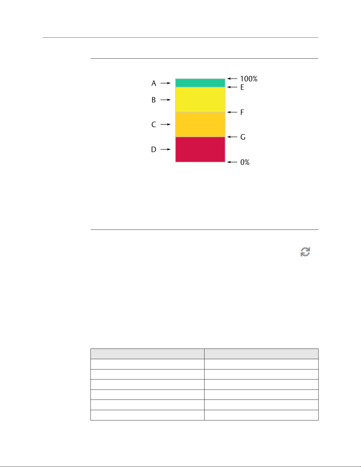
Figure 3-14 explains the health score and the different health levels Healthy, Advise,
Warning and Critical.
28 MHM-97924-PBF, Rev. 3.2
Operating Manual Functional overview
MHM-97924-PBF June 2022
Figure 3-14: Asset health score
A. Healthy ≥90%
B. Advise ≥60% and <90%
C. Warning ≥30% and <60%
D. Critical <30%
E. Limit value – Advise (90%)
F. Limit value – Warning (60%)
G. Limit value – Critical (30%)
Health calculation cycle
The health of the configured assets is calculated every 60 minutes. Click the button in
the analytics display to manually start a health calculation (see Status overview – asset).
The health is also calculated when Save & Close is clicked in the asset configuration dialog
or after a reboot of the AMS Asset Monitor. A manually started health calculation does not
affect the 60 minutes cycle.
3.5 Trend data storage
The data visualized by the overall assets health trend (see Figure 8-1) and the asset specific
health trends (see Figure 8-10) are permanently saved on the AMS Asset Monitor. The data
is aggregated depending on the age of the data:
Table 3-9: Data aggregation
Data age Interval
≤5 minutes 1 value per second
>5 minutes and ≤1 hour 10 seconds
>1 hour and ≤1 day 5 minutes
>1 day and ≤1 week 30 minutes
>1 week and ≤1 month 2 hours
>1 month and ≤1 year 1 day
MHM-97924-PBF, Rev. 3.2 29

Functional overview Operating Manual
June 2022 MHM-97924-PBF
Table 3-9: Data aggregation
Data age Interval
>1 year and ≤14 years 1 week
Time stamp
Trend data and alerts are stored together with the current time of the AMS Asset Monitor.
3.6 Basic protection
The AMS Asset Monitor is equipped with basic functions for machine protection. The
following signal evaluations for dynamic signals are available:
0-to-Peak
Peak-to-Peak
RMS
Equivalent peak
(√2 * Velocity
RMS)
The measured value is proportional to the vibration of the
supervised asset in 0-to-peak evaluation.
The measured value is proportional to the vibration of the
supervised asset in peak-to-peak evaluation.
The measured value is proportional to the vibration of the
supervised asset in RMS3 evaluation.
The measured RMS value of the supervised asset is multiplied by √2
to get the Equivalent peak value for the output. This evaluation is
available for VI Piezo CHARMs.
.
(continued)
PeakVue
All values measure by CHARMs or imported as an external data point can be supervised on
limit violations. Configure alarm limits in the Measurement alerts dialog of the asset
where the CHARM or external data point is used that provides the value to be supervised.
PeakVue detects impact-like events such as bearing defects. The
detected amplitudes can be supervised by user defined alarm limits.
This evaluation is available for VI Piezo CHARMs.
3.7 Predicates and data collections
Predicates
The AMS Asset Monitor is equipped with a logic editor to define predicates to control the
execution of data collections and asset health calculations (see Health calculation) based
on input signals such as measuring values or logic states. Sources for a predicate:
• Input CHARMs
• External data points
• Assets (speed value)
• Other predicates (predicate-in-predicate)
Up to 20 predicates with up to 10 different conditions can be defined.
3
Root Mean Square
30 MHM-97924-PBF, Rev. 3.2

Operating Manual Functional overview
MHM-97924-PBF June 2022
Data collections
The AMS Asset Monitor has a data collection function to send specific waveform data
through the AMS Machine Works interface to AMS Machine Works. The data collection is
controlled by user defined time intervals and predicates. Currently, one data collection is
supported by AMS Asset Monitor and AMS Machine Works. The data collection contains up
to 24 waveforms. A set of five preconfigured data collection setups with maximum signal
frequency (Fmax) and lines of resolution (LOR), three for vibration signals and two for
PeakView, are available for the configuration of each waveform. One vibration and one
PeakVue4 waveform can be collected for each CHARM. The waveform data is sent along
with average speed data. The average speed is calculated over the length of time of the
collected waveform. CHARM waveforms are not collected if the CHARM is disabled, has an
error, or the configuration is deleted. This function requires AMS Machine Works 1.7 or
higher.
4 Available for VI Piezo CHARMs.
MHM-97924-PBF, Rev. 3.2 31

Functional overview Operating Manual
June 2022 MHM-97924-PBF
32 MHM-97924-PBF, Rev. 3.2

Operating Manual First steps
MHM-97924-PBF June 2022
4 First steps
This chapter describes the connection to the AMS Asset Monitor for the first time, provides
an overview about the web interface, and explains the basic settings required for
operating the AMS Asset Monitor.
4.1 Requirements on the configuration device
The AMS Asset Monitor Web Interface running on the AMS Asset Monitor provides the
user interface to configure the AMS Asset Monitor and to provide status and health
information. AMS Asset Monitor Web Interface runs on desktop and mobile devices with a
compatible web browser. Requirements for the first connection:
• PC, laptop, or similar with one free Ethernet port for a direct one-to-one connection to
the AMS Asset Monitor
• Ethernet cable (CAT 5 or better)
• Compatible web browser
Table 4-1: Compatible web browser
Web browser Version
Google Chrome 78.0 or later
Microsoft Edge 79.0 or later
Mozilla Firefox 70 or later
Apple Safari 12.1 or later
As a first action at any kind of browser issues press Ctrl+F5 to override the browser
cache and to reload the page.
4.2 Connect to the AMS Asset Monitor
Procedure
1. Ensure that the AMS Asset Monitor is powered by a +24 V DC power supply.
2. Open the AMS Asset Monitor.
The default configuration interface is the lower sockets of the three RJ-45 sockets.
See the AMS Asset Monitor Installation Guide for details.
MHM-97924-PBF, Rev. 3.2 33

First steps Operating Manual
June 2022 MHM-97924-PBF
Figure 4-1: Configuration and data exchange interface
A. RJ-45 Ethernet connector for configuration and to connect to subsequent
systems.
3. Connect the configuration device through the Ethernet connection to the AMS
Asset Monitor.
Note
The default IP address of the configuration interface is 169.254.153.110
4. Ensure that the Ethernet settings of the configuration device match to the IP
address of the AMS Asset Monitor.
5. Start your web browser and enter the default IP address.
6. Add a certificate to verify the identity of the AMS Asset Monitor Web Interface
(optional). See Certificates.
The login dialog of the AMS Asset Monitor Web Interface opens.
7. Enter user name and password to log on to the AMS Asset Monitor Web Interface.
Credentials for the first login:
User name: admin
Password: admin
At the first login, the dialog to change the password appears. Change the password
of the administration account.
34 MHM-97924-PBF, Rev. 3.2

Operating Manual
MHM-97924-PBF June 2022
Figure 4-2: Change password at login
First steps
Depending on the user account settings (see Users), a change of the password at
the login could also be necessary.
8. Read and confirm the software license agreement.
The home screen of the AMS Asset Monitor Web Interface opens. It is
recommended that not more than five browsers simultaneously connect to the
AMS Asset Monitor Web Interface.
4.3 Log out from AMS Asset Monitor Web Interface
Procedure
1. To log out from the AMS Asset Monitor Web Interface click the user icon in the
upper right corner.
The user menu opens.
2. Click Logout.
The AMS Asset Monitor Web Interface closes and the login dialog appears.
Note
All unsaved changes are lost.
Note
The current user is automatically logged out 30 minutes after the last user action in
the AMS Asset Monitor Web Interface.
4.4 Overview web interface
The AMS Asset Monitor comes with its own web interface called AMS Asset Monitor Web
Interface. This section describes the main function of AMS Asset Monitor Web Interface.
MHM-97924-PBF, Rev. 3.2 35
First steps
June 2022 MHM-97924-PBF
Operating Manual
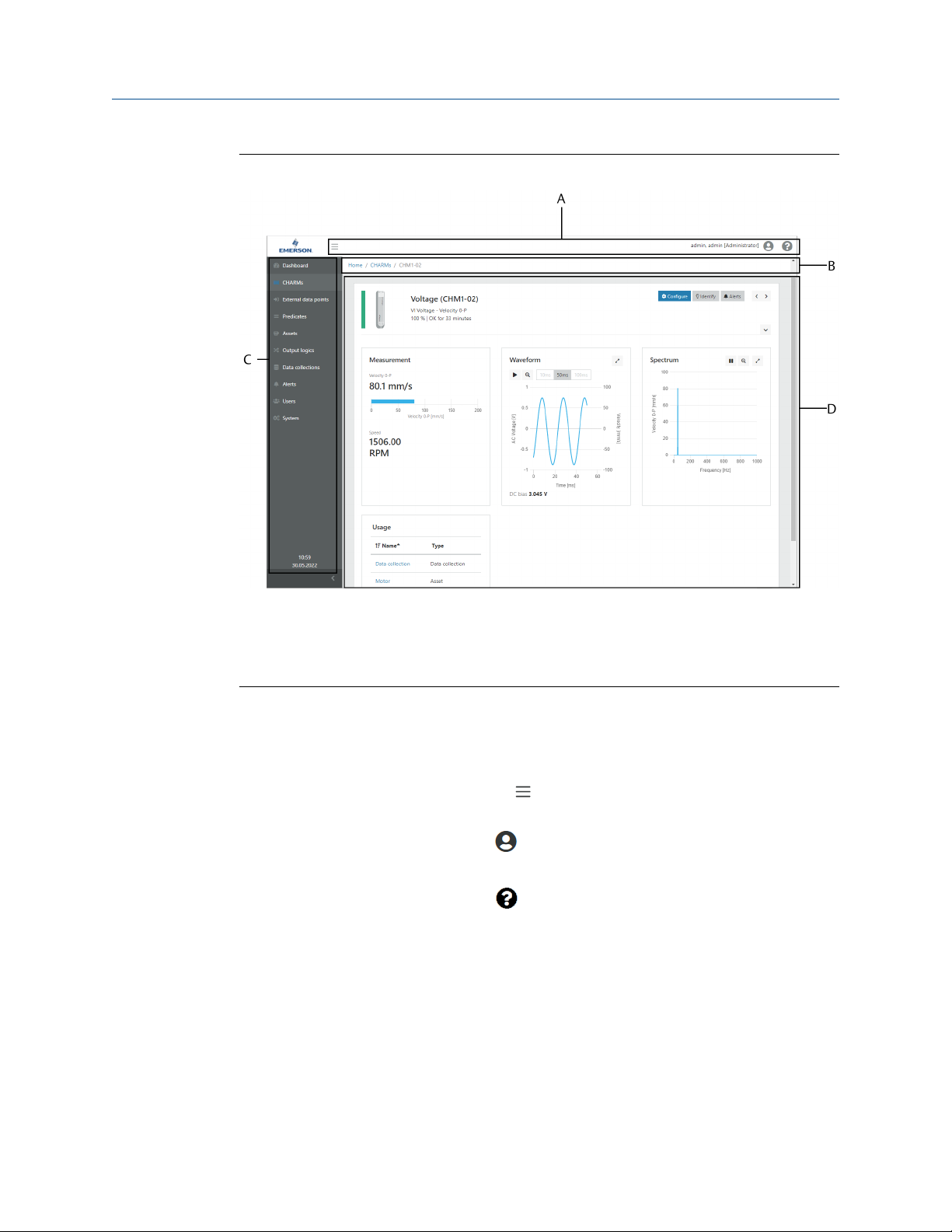
Figure 4-3: AMS Asset Monitor Web Interface – Overview
A. Symbol bar
B. Navigation bar
C. Sidebar
D. Content area
Symbol bar
The symbol bar contains several general buttons and displays the name of the logged in
user including the assigned user right level in brackets.
Sidebar
Click the sidebar button to close or open the Sidebar.
button
User button
Click the user button to open or close the user menu. See User
menu.
Help button
Click the help button to open or close the help menu.
Help
About AMS Asset
Monitor
Click Help to open the online help.
Click About AMS Asset Monitor to open version
and licenses information.
Navigation bar
The navigation bar indicates the location of the currently displayed page. Click the
highlighted page names to easily navigate through the hierarchy.
36 MHM-97924-PBF, Rev. 3.2

Operating Manual First steps
MHM-97924-PBF June 2022
Sidebar
List of all pages. Click a page to open it. The current time and date are displayed below the
pages.
Dashboard
CHARMs
External data
points
Predicates
Assets
Output Logics
Data collections
Main page of AMS Asset Monitor Web Interface with a general
overview containing several health and status information:
• Assets status
• CHARMs status
• Device status
• Overall assets health trend
Configuration and status overview of the installed CHARMs.
Configuration of external data points to import data through the
Modbus and OPC UA interface. The imported data can be used as
input for analytics and measurements of an asset.
Configuration of predicates to control the execution of certain actions
such as calculating an asset health only if the machine is running
within a certain speed range.
Configuration of machine and machine parts to be supervised.
Assignment of asset statuses and measurements to a digital output by
using a predefined condition.
Configuration of a data collection to send specific waveform data,
collected based on schedules and optional predicates, for further
analysis to AMS Machine Works.
Alerts
Users
System
Content area
The content of the selected page is displayed in this area.
List of events from assets, CHARMs, external data points, predicates,
and data collections.
Overview of existing users and user administration. Visible for users
with administrator rights.
Configuration and status overview of the AMS Asset Monitor.
4.5 Enter basic settings
Enter the basic settings for the operation of the AMS Asset Monitor.
MHM-97924-PBF, Rev. 3.2 37

First steps Operating Manual
June 2022 MHM-97924-PBF
Figure 4-4: System configuration dialog
4.5.1
Procedure
1. Go to System and click Configure.
The dialog for the system configuration opens. Different dialogs for the system
configuration are available.
2. Go through the dialogs Basics, Network IPv4, DNS, and Date and time and
complete the fields in accordance to your needs. The dialogs AMS Machine Works,
Modbus TCP, OPC UA, and Plantweb Optics Data Collector can be completed
later, for example after the configuration of the external data points.
3. Click Save & Close to save the settings on the AMS Asset Monitor or click Cancel to
discard the entries.
The changes take effect immediately. Use the new network settings for the
connection to the AMS Asset Monitor the next time.
Basics
Enter a name and a description for the AMS Asset Monitor.
Name
Enter a name for the AMS Asset Monitor. The change of the name requires
an update of the SSL certificate and can also affect OPC UA, Modbus TCP,
AMS Machine Works, and Plantweb Optics Data Collector connections.
Note
When updating the firmware from version 1.x.x to 2.x.x, a name already
configured in version 1.0.0 is moved to Description and the serial number
of the AMS Asset Monitor is entered instead.
Description
38 MHM-97924-PBF, Rev. 3.2
Enter a description of the AMS Asset Monitor.

Operating Manual
MHM-97924-PBF June 2022
First steps
4.5.2 Network IPv4
Enter network settings for the communication with the AMS Asset Monitor.
To avoid connection issues, do not use the IP address ranges listed in Table 4-2, regardless
of whether the IP addresses are entered manually or assigned automatically using a DHCP
server.
Table 4-2: Excluded IP address ranges
IP address Subnet mask Gateway Comment
10.123.255.0 255.255.255.0 10.123.255.0/24 Internal use
127.0.0.0 255.0.0.0 127.0.0.0/8 Loopback, internal use
169.254.0.0 255.255.0.0 169.254.0.0/16 AUTO-IP range, do not
use in production
environments, default
IP address of the AMS
Asset Monitor is
169.254.153.110. Do
not use this range for
LAN2.
Note
Ensure that the networks of LAN1 and LAN2 do not overlap.
LAN1
These settings are assigned to the lower socket of the three RJ-45 sockets. This 1 Gbit/s
interface is the default interface for configuration and data exchange with subsequent
systems.
Figure 4-5: Configuration and data exchange interface
A. RJ-45 Ethernet connector for configuration and to connect to subsequent systems.
• Select Obtain an IP address automatically to automatically obtain an IP address from
a DNS server.
• Select Use the following IP address to enter IP address settings manually.
With this selection, the entry fields for manually entering the IP address are active. The
setting for the DNS server and for automatically obtaining the IP address of a NTP
server (Date and time → Obtain an IP address automatically) is deactivated.
Ask your local network administrator for the required address data.
MHM-97924-PBF, Rev. 3.2 39

First steps Operating Manual
June 2022 MHM-97924-PBF
IP address
Subnet mask
Gateway
LAN2
These settings are assigned to the two upper sockets of the three RJ-45 sockets. These 100
Mbit/s interfaces are for building up an AMS Asset Monitor group of AMS Asset Monitors.
Because of the possible network traffic, Emerson recommends to daisy chain no more
than eight AMS Asset Monitors.
Figure 4-6: LAN2 interface
A. Ethernet switch with two RJ-45 connectors to daisy chain AMS Asset Monitors.
Enable
Place a checkmark in the box to enable the LAN2 interface. The entry field for
entering the IP address becomes active. Ask your local network administrator for
the required address data.
Enter the IP address according to the IPv4 standard.
Enter the subnet mask.
Enter the gateway address.
IP address
Subnet mask
Gateway
4.5.3 DNS
The AMS Asset Monitor can use a Domain Name System (DNS) server to obtain an IP
address.
DNS
settings
Domain
name
Enter the IP address according to the IPv4 standard.
Enter the subnet mask.
Enter the gateway address.
• Select Obtain an IP address automatically to automatically obtain an IP
address from a DNS server. This option is selectable if Obtain an IP
address automatically is also activated for Network IPv4 → WAN/LAN.
• Select Use the following IP address to enter the IP address of a DNS
server.
With this selection, the entry field DNS address for entering the IP address
is active.
Ask your local network administrator for the required address data.
Optionally you can enter a domain name to access the AMS Asset Monitor via
the name instead of the IP address. The configured name of the AMS Asset
Monitor (System → Configure → Basic → Name) defines the sub-domain.
40 MHM-97924-PBF, Rev. 3.2

Operating Manual First steps
MHM-97924-PBF June 2022
Example: The entered Name → MyAssetMonitor and the entered Domain
name → example.com builds MyAssetMonitor.example.com.
The change of the domain name requires an update of the SSL certificate and
can also affect OPC UA, Modbus TCP, and Data Collector connections.
4.5.4 Date and time
The internal time of the AMS Asset Monitor can manually be set or it can be synchronized
with the time provided by a Network Time Protocol (NTP) server to keep the AMS Asset
Monitor system's time current. This function requires a permanent connection to a NTP
server.
CAUTION
The proper system time setting is crucial for the operation of the AMS Asset Monitor.
Verify the system time and make any necessary time adjustments before continuing with
the AMS Asset Monitor configuration.
A significant time adjustment of the AMS Asset Monitor causes the following issues:
• The current user is logged out after the system time is set more than 30 minutes
forward compared to the current system setting.
Log in again.
• The AMS Asset Monitor reboots automatically after the system time is set more than
15 minutes (or more than 30 seconds, if time is manually set) backward compared to
the current system setting. Health trends and alert lists do not work correctly for some
time, waiting changed system time to catch up with the latest collected data
timestamps. Depending on the time deviation there are two options to solve the issue
– wait or reset:
— Less than a few hours: Wait until the changed system time catches up with the
latest collected data timestamps. See next option for how to solve the time
deviation immediately.
— More than a day: Reset the AMS Asset Monitor to factory default (see Reset to
factory default) and restore the configuration by using a backup file (see Restore) or
create a new configuration.
Emerson recommends to use the time server synchronization to always ensure a correct
AMS Asset Monitor system time setting.
The current date and time of the AMS Asset Monitor (System time) is displayed at the top
of the configuration page.
Time zone
Synchronize with
time server
Obtain an IP
address
automatically
Select the time zone where the AMS Asset Monitor is installed.
Place a checkmark in the box to activate the automatically
synchronization of the system time. Use a reliable NTP server.
Only if Synchronize with time server is selected. Select this option
to automatically connect to an arbitrary NTP server. This option is
selectable if Obtain an IP address automatically is also activated
for Network IPv4 → WAN/LAN.
MHM-97924-PBF, Rev. 3.2 41

First steps Operating Manual
June 2022 MHM-97924-PBF
Use the following
NTP server address
Only if Synchronization with time server is selected. Select this
option to enter an IP address of a specific NTP server. The assigned
entry field for the IP address is enabled.
From local PC/
device
Only if Synchronization with time server is not selected. Click Set
date and time now to synchronize the time of the AMS Asset
Monitor with the time of the local PC or other device connected to
the AMS Asset Monitor.
Manually
Only if Synchronization with time server is not selected. Click the
entry fields to open the dialogs to select date and time.
• Date entry: Use the left and right arrows to select a month then
click a day to select it.
• Time entry: Use the up and down arrows to enter the time or
type it in.
Click Set time and date now to activate the date and time entry.
The AMS Asset Monitor contains a real time clock with a 48-hour buffer in case of a failed
power supply.
42 MHM-97924-PBF, Rev. 3.2

Operating Manual Data and network security
MHM-97924-PBF June 2022
5 Data and network security
This chapter provides basic information necessary to setup a system in accordance to
cyber security requirements. Emerson recommends working with qualified IT personnel to
ensure your installation complies with your plant's network security policy and industry
best practices. For more detailed information about cyber security see AMS Product
Security Documentation (AMS-SEC-PSG-001).
5.1 Certificates
The AMS Asset Monitor uses the https protocol5 for encrypted communication. The AMS
Asset Monitor creates a certificate that must be added to your browser as a trusted root
certificate. Because of the variety of browsers the adding of a certificate is described in a
general way.
Procedure
1. Download the certificate from the AMS Asset Monitor to your computer.
a) At the first connection to the AMS Asset Monitor the browser indicates an
insecure connection. Open the page information.
b) Open the certificate information.
c) Save the certificate with a unique name.
2. Open the settings of your browser and go to the certificate's administration.
3. Add the stored certificate as a trusted root certificate to your browser.
4. Restart the browser and reconnect to the AMS Asset Monitor.
5.2 Firewall considerations
Before installing the AMS Asset Monitor ensure that the port 443 is open through all
firewalls between the AMS Asset Monitor and the computers used for the communication.
Depending on the interfaces used, ensure that the ports listed in Table 5-1 are open.
Table 5-1: Ports to be opened for interfaces
Interface Port
AMS Machine Works 443
OPC UA 4840
Modbus TCP 502
Plantweb Optics Data Collector 443
5 Hyper Text Transfer Protocol – Secure
MHM-97924-PBF, Rev. 3.2 43

Data and network security Operating Manual
June 2022 MHM-97924-PBF
5.3 Additional security considerations
Incident management
Contact Emerson Product support to report cyber security related incidents. See Technical
support for contact details.
User accounts
User accounts with different roles can be configured. The available roles and assigned
permissions are explained in Parameter description.
The default user has the role Administrator. For login credentials see Connect to the AMS
Asset Monitor.
Safe deletion of the AMS Asset Monitor's data
Emerson recommends deleting all user defined data from the AMS Asset Monitor before
the disposal of the device or before transferring it to a third party. Use the reset function to
safely delete all customized data of the AMS Asset Monitor. See Reset to factory default for
details.
44 MHM-97924-PBF, Rev. 3.2

Operating Manual Configure the AMS Asset Monitor
MHM-97924-PBF June 2022
6 Configure the AMS Asset Monitor
There are eight different elements for the configuration of the AMS Asset Monitor:
CHARMs
External data
points
Predicates
Assets
Output Logics
Data collections
Users
System
Configuration of each installed CHARM.
Configuration of points for the data import through Modbus and OPC
UA.
Configuration of predicates to control the execution of certain actions
such as calculating an asset health only if the machine is running
within a certain speed range.
Entry of basic data and bearing information of the supervised asset,
mapping of the available sources to the measurement locations,
defining of measurement alarms, and selection of health calculations.
Assignment of an asset status to a digital output by using a predefined
condition.
Configuration of the acquisition of waveform data for sending to AMS
Machine Works.
Administration of different users.
Configuration of the AMS Asset Monitor – name, description,
communication, and time settings.
Note
The system dialogs Basics, Network IPv4, DNS, and Date and time
are generally configured at the first start of the AMS Asset Monitor.
See Enter basic settings.
Prerequisites
• Powered AMS Asset Monitor.
• Connected configuration device (PC or Laptop).
• All CHARMs required for the measuring task are already installed.
Note
During the system start the installed CHARMs are automatically recognized by the AMS
Asset Monitor.
• Installed address plug.
General sequence for the configuration of the AMS Asset Monitor:
1. System (dialogs Basics, Network IPv4, DNS, and Date and time)
2. User
3. CHARMs
4. External data points
5. Predicates
MHM-97924-PBF, Rev. 3.2 45

Configure the AMS Asset Monitor Operating Manual
June 2022 MHM-97924-PBF
6. System (dialogs AMS Machine Works, OPC UA, Modbus TCP, and Plantweb Optics
Data Collector)
7. Assets
8. Output logics
9. Data collections
6.1 Configuration page overview
The configuration page of each configurable element (CHARMs, External data points,
Assets, Output logics, Data collections, and System) is structured in the same way.
Figure 6-1: Structure configuration page
A. Navigation bar
B. Parameter groups (Asset configuration only)
C. Notification area
D. Input area
E. Buttons
Navigation bar
The navigation bar indicates the location of the currently displayed page. Click the
highlighted page names to easily navigate backwards through the pages visited before.
Parameter groups
Related parameters of the asset configuration are combined in groups. Select a group to
open the parameters in the input area.
46 MHM-97924-PBF, Rev. 3.2
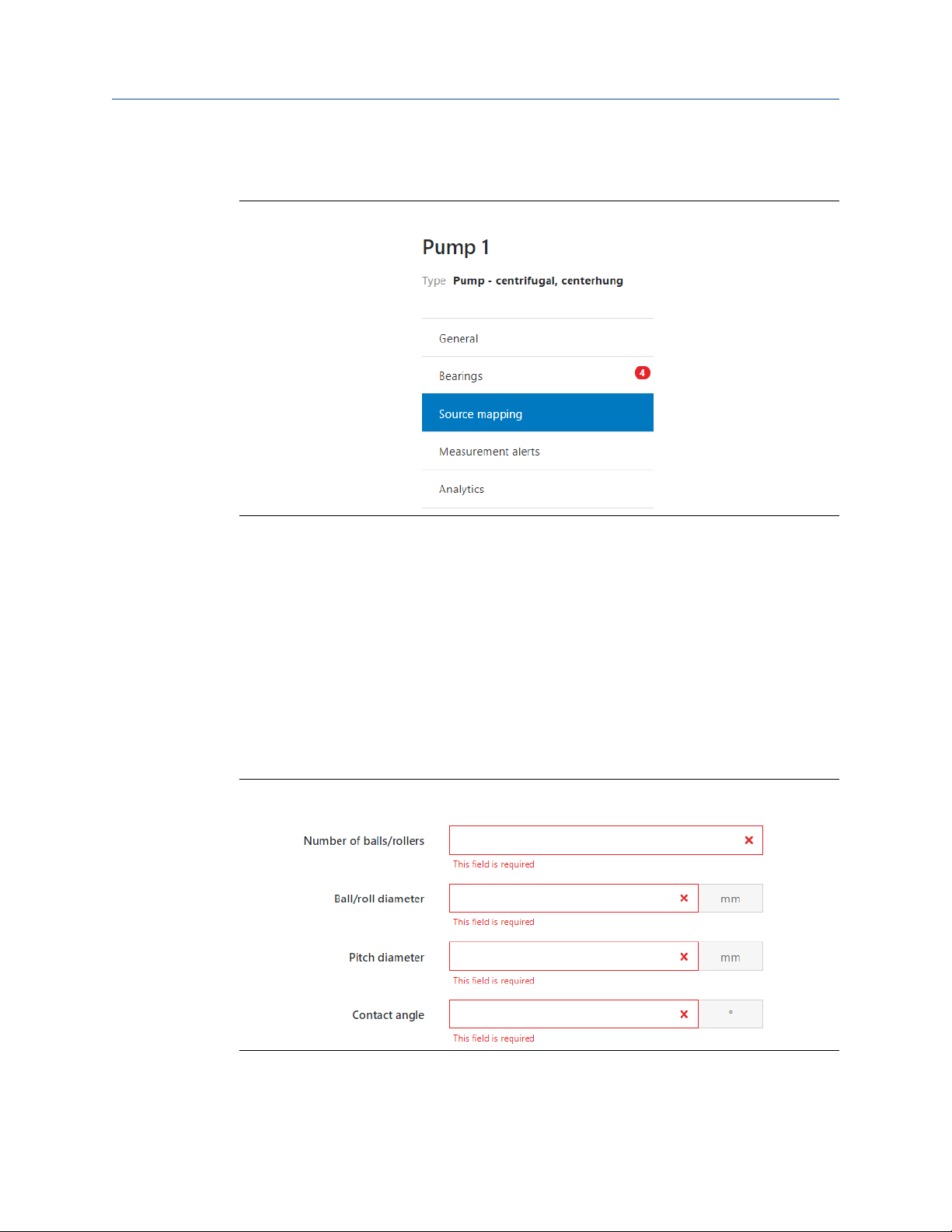
Operating Manual Configure the AMS Asset Monitor
MHM-97924-PBF June 2022
Wrong settings within a parameter group are indicated behind the group name with a red
dot that displays the number of errors.
Figure 6-2: Configuration error indication – parameter group
Notification area
The notification area shows in which other element the configured element is used.
Example: A configured asset is also used in an output logic configuration and in a
predicate. Then the name of the output logic and the name of the predicate are listed in
the notification area.
Input area
The input area lists all parameters of a selected parameter group. Enter here the
configuration parameters of the selected parameter group.
Required entry fields are red framed if an entry is missing or the entry is out of the
permissible range.
Figure 6-3: Configuration error indication – entry fields
Buttons
Buttons to decline or accept the parameter entries.
MHM-97924-PBF, Rev. 3.2 47

Configure the AMS Asset Monitor Operating Manual
June 2022 MHM-97924-PBF
A configuration cannot be saved as long as there are entry fields with an error.
An information box, as shown in Figure 6-4, appears when a configuration is to be saved
that affects other configuration elements. Click OK to continue saving the configuration,
then check the listed configuration elements and update them as required.
Figure 6-4: Overview of configuration elements affected by the configuration change
6.2 CHARMs
Recomended procedures – CHARMs describes procedures to create and change a
configuration, and to remove or replace a CHARM. Parameter description – CHARMs
describes the parameters of all compatible CHARMs.
6.2.1
Recomended procedures – CHARMs
First configuration – CHARMs
Procedure
1. Select CHARMs from the sidebar.
2. Open the configuration dialog.
• In the Tiles view, click the gear wheel below the icon of the CHARM to be
configured.
• In the List view, click Configure in the column Action in the row of the CHARM to
be configured.
3. Enter configuration parameters according to the task of the CHARM.
4. Click Save & Close to send the configuration to the CHARM.
48 MHM-97924-PBF, Rev. 3.2

Operating Manual Configure the AMS Asset Monitor
MHM-97924-PBF June 2022
Configuration change – CHARMs
CAUTION
Any work on the system may impair asset health monitoring and machine protection.
Procedure
1. Select CHARMs from the sidebar.
2. Open the configuration dialog.
• In the Tiles view, click the gear wheel below the icon of the CHARM to be
configured. See Tiles view – CHARMs.
• In the List view, click Configure in the column Action in the row of the CHARM to
be configured. See List view – CHARMs.
3. Check the configuration parameters and change them according to your needs.
4. Click Save & Close to send the configuration to the CHARM.
Remove or replace a CHARM
CAUTION
Any work on the system may impair asset health monitoring and machine protection.
The configuration of the CHARM is part of the AMS Asset Monitor configuration and
assigned to the slot where the CHARM is installed. The configuration is not stored in the
CHARM. This has the advantage that the CHARM can be replaced without creating a new
configuration. The CHARM type is automatically detected by the AMS Asset Monitor. If the
new CHARM is equal to the CHARM installed before in the slot, it starts working with the
configuration made for the slot. If another CHARM type is installed in the slot, the system
issues a type mismatch message.
See AMS Asset Monitor Installation Manual for how to physically install or remove a
CHARM.
Remove a CHARM
Procedure
1. Select CHARMs from the sidebar.
2. Open the CHARM overview.
• In the Tiles view, click the CHARM icon.
• In the List view, click the CHARM designation in column Name in the row of the
respective CHARM.
3. Remove the CHARM from the AMS Asset Monitor.
The system displays a message that the CHARM is defect or missing. This message
contains a button to delete the configuration.
4. Click Discard configuration to delete the configuration of the CHARM.
MHM-97924-PBF, Rev. 3.2 49

Configure the AMS Asset Monitor Operating Manual
June 2022 MHM-97924-PBF
The configuration is deleted and the slot is prepared for the installation of another
CHARM type.
Replace a CHARM by the same CHARM type
The replacement of a CHARM by the same CHARM type dose not require any user action in
AMS Asset Monitor Web Interface. Use AMS Asset Monitor Web Interface to follow the
automatic process.
Procedure
1. Select CHARMs from the sidebar.
2. Open the CHARM overview.
• In the Tiles view, click the CHARM icon.
• In the List view, click the CHARM designation in column Name in the row of the
respective CHARM.
3. Remove the CHARM from the AMS Asset Monitor.
The system displays a message that the CHARM is defect or missing.
4. Install the new CHARM of the same type.
The new CHARM is automatically detected by the AMS Asset Monitor and starts
working.
6.2.2
Replace a CHARM by another CHARM type
Procedure
1. Select CHARMs from the sidebar.
2. Open the CHARM overview.
• In the Tiles view, click the CHARM icon.
• In the List view, click the CHARM designation in column Name in the row of the
respective CHARM.
3. Remove the CHARM from the AMS Asset Monitor.
The system displays a message that the CHARM is defect or missing.
4. Install another CHARM.
The system issues a type mismatch message. This message contains a button to
delete the configuration.
5. Click Discard configuration to delete the configuration of the old CHARM.
The configuration is deleted and the system indicates that the installed CHARM is
not configured. This message contains a button to open the configuration page.
6. Click Configure and complete the configuration.
Parameter description – CHARMs
Each CHARM has a specific set of parameters to define function and measurement. The
CHARM specific parameters of all CHARMs compatible with the AMS Asset Monitor are
described in the following chapters. The common parameters are described subsequently.
50 MHM-97924-PBF, Rev. 3.2

Operating Manual Configure the AMS Asset Monitor
MHM-97924-PBF June 2022
Note
The measuring signal used for the rules calculation is not influenced by the signal
evaluation and evaluation filters set in the CHRAM configuration.
The type of the installed CHARM, date and time of the last configuration, and the name of
the user who made the last configuration is displayed at the top of the configuration page.
Common parameters, available for all CHARM types:
Basic
Enabled
Name
Description
Cabling ID
Place a checkmark in the box to enable the function of the CHARM.
Enter a name for the CHARM.
Enter a description of the CHARM.
Enter the identification code of the measurement location.
VI Piezo CHARM
Sensor type
Unit
Evaluation
• Select Velocity if a piezoelectric sensor is connected that provides a
signal proportional to the velocity of the vibration (velocity sensor).
• Select Acceleration if a piezoelectric sensor is connected that provides
a signal proportional to the acceleration of the vibration
(accelerometer).
Select a unit in accordance to the technical data of the connected sensor
from the drop-down list. The available options depend on the selected
sensor type. It is not necessary that the unit aligns to the selected system
of units configured for the logged in user. The unit is automatically
converted to the user's system of units for the following parameters.
Select the required signal evaluation from the drop-down list. Which
evaluations are available depend on the selected sensor type. The VI Piezo
CHARM has an integrated signal integration function. If an accelerometer is
connected, acceleration and velocity evaluations can be selected. With a
velocity sensor, velocity and displacement evaluations can be selected.
Table 6-1: Selectable evaluations
Accelerometer Velocity sensor
Integration not
active
Acceleration 0-P +
PeakVue
Acceleration P-P +
PeakVue
RMS1 Acceleration
+ PeakVue
MHM-97924-PBF, Rev. 3.2 51
Integration
active
Velocity 0-P +
PeakVue
Velocity P-P +
PeakVue
RMS1 Velocity +
PeakVue
Integration not
active
Velocity 0-P Displacement 0-P
Velocity P-P Displacement P-P
RMS1 Velocity RMS
Integration
active
1
Displacement

Configure the AMS Asset Monitor Operating Manual
June 2022 MHM-97924-PBF
Table 6-1: Selectable evaluations
Accelerometer Velocity sensor
Integration not
active
PeakVue --- ---
1
Root Mean Square
Integration
active
PeakVue
PeakVue (Peak Values) is a method to detect impact-like events such as
bearing defects. This function can be used if Sensor type → Acceleration is
selected.
Use this evaluation in combination with diagnose calculations for bearings
to detect bearing faults.
Figure 6-5: Signal evaluation explanation
(continued)
Integration not
active
Integration
active
A. 0-P: zero-to-peak evaluation.
B. P-P: peak-to-peak evaluation
C. RMS: Root Mean Square evaluation
D. Sensor signal
E. Voltage
F. Time
Equivalent
peak
(√2*Velocity
RMS)
Place a checkmark in the box to enable the equivalent peak calculation.
This function is available for signals from accelerometers with signal
evaluation With selected evaluations based on a connected
accelerometer the PeakVue value is also displayed in the CHARM's
status overview and available through the OPC UA interface.Velocity 0-
52 MHM-97924-PBF, Rev. 3.2

Operating Manual Configure the AMS Asset Monitor
MHM-97924-PBF June 2022
P + PeakVue and for velocity sensors with signal evaluation Velocity 0P. The RMS value is multiplied by √2 to get the Equivalent peak value
for the output. An active equivalent peak calculation is indicated in the
CHARM's status view (see Measurement displays).
Sensitivity
Evaluation
filter
PeakVue
evaluation
filter
Enter the sensitivity of the connected piezoelectric sensor.
Select a bandpass filter in accordance to your measurement
application. See Table 6-2 for some example settings.
Table 6-2: Example filter settings
Standard/Application Evaluation Filter range
ISO 20816 Velocity RMS 2 to 1000 Hz or
10 to 1000 Hz
API 670 Velocity RMS 10 to 1000 Hz or 5 to
1000 Hz for assets with
speed <750 rpm
Acceleration 0-to-Peak 10 to 5000 Hz
Low speed applications
such as hydropower
plant
Velocity RMS 1 to 600 Hz or
0.3 to 200 Hz
Select a high pass filter or a bandpass filter for the PeakVue evaluation.
See Table 6-3 for some example settings depending on the asset speed
when using antifriction bearings.
Table 6-3: Example filter settings
Speed Filter
<100 rpm 50 Hz (high-pass)
optionally 20 to 150 Hz (band-pass)
or 50 to 300 Hz (band-pass)
100 to 700 rpm 500 Hz (high-pass)
700 to 1500 rpm 1000 Hz (high-pass)
1500 to 3000 rpm 1000 Hz (high-pass)
or 2000 Hz (high-pass)
3000 to 4000 rpm 2000 Hz (high-pass)
or 5000 Hz (high-pass)
>4000 rpm 5000 Hz (high-pass)
1
When a 5000 Hz high pass filter is selected ensure that the used
accelerometer is stud-mounted to avoid high frequency damping.
1
1
Note
The selected Evaluation filter and PeakVue evaluation filter are used
for the CHARM's internal signal processing. The resulting measurement
values are used for the measurement alert function (see Measurement
MHM-97924-PBF, Rev. 3.2 53
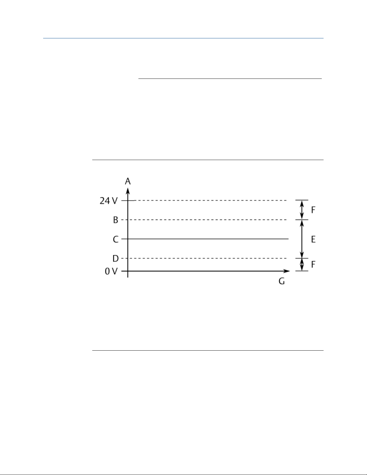
Configure the AMS Asset Monitor Operating Manual
June 2022 MHM-97924-PBF
alerts) and are shown in the CHARM's status view. These filters have no
influence on the signals used for the rules calculation.
Current supply
Place a checkmark in the box to enable the current supply of the
CHARM. Enter a current in accordance to the sensor documentation to
supply the sensor.
DC bias range
Enter a lower limit value and an upper limit value to define a DC bias
range for the CHARM supervision. See technical data of the connected
sensor for the typical bias voltage. The CHARM's supervision function
indicate a not OK status if the DC part of the input voltage is out of the
defined OK range.
If the input voltage returns to the OK range the not OK status is reset.
Figure 6-6: DC bias range
A. DC voltage range
B. Upper limit value
C. Bias (DC offset)
D. Lower limit value
E. Input signal OK range
F. Input signal not OK range
G. Time
Measurement
range (±)
Enter a limit value to define a ± OK range for the CHARM supervision.
See technical data of the connected sensor for the measuring range.
The CHARM's supervision function indicates a not OK status if the
measuring value is out of the defined OK range.
If the measurement value returns to the OK range the not OK status
is reset.
Display range
Enter a lower limit value and an upper limit value to define a range
for displaying the measured value.
54 MHM-97924-PBF, Rev. 3.2

Operating Manual Configure the AMS Asset Monitor
MHM-97924-PBF June 2022
VI Tach CHARM
Requirements and information
An input signal with a minimum signal amplitude of 2.0 V peak-to-peak is required for a
reliable speed measurement. Ensure that the sensor used for the speed measurement is
adjusted so that the signal amplitude is always higher than the minimum required signal
amplitude.
The key-signal is always generated based on one rotation, regardless of the setting for
Measurement mode. Even if a partial gear measuring mode such as Standard or Standard
+ stabilization (max. speed < 720; increased update time) is used for the speed
measurement.
Parameter description
Sensor
type
Voltage
limits
Note
If no sensor is connected to the VI Tach CHARM or there is a sensor cable break, the status
overview indicates an open-circuit voltage in the range of +12 V to +17 V. The open-circuit
voltage is caused by the sensing current of approximately 240 μA, required for the open
sensor circuit detection of Hall-effect and passive magnetic sensors. This behavior is
independently of the configured sensor type.
• Select Hall effect if a Hall-effect sensor is connected. The maximum
permissible input voltage range is 0 to + 24 V.
• Select Passive magnetic pickup if a variable reluctance sensor (magnetic
pickup) is connected. The maximum permissible input voltage range is 85
V peak-to-peak (30.3 V AC).
• Select Proximity probe + converter if an eddy current measuring chain is
connected. The maximum permissible input voltage range is 0 to -24 V.
This entry field is available if Sensor type → Proximity probe + converter is
selected.
Enter a lower limit value and an upper limit value to define a signal range for
the sensor supervision. The CHARM's supervision function indicates a not OK
status if the input voltage is out of the defined OK range.
If the input voltage returns to the OK range the not OK status is reset.
MHM-97924-PBF, Rev. 3.2 55

Configure the AMS Asset Monitor Operating Manual
June 2022 MHM-97924-PBF
Figure 6-7: Input signal with supervision limits
A. Input voltage
B. Upper limit value
C. Sensor adjustment voltage
D. Lower limit value
E. Maximum output voltage
F. Time
G. Tooth gap
H. Tooth
I. Input signal not OK range
J. Input signal OK range
Wheel type
• Select One tooth if the sensor measures at a key-mark on the shaft
or at a trigger wheel with one tooth.
• Select Multi tooth if the sensor measures at a trigger wheel with
more than one tooth.
Number of
teeth
This entry field is available if Wheel type → Multi tooth is selected.
Enter the number of teeth of the multi-tooth wheel on which the
sensor is mounted.
Symmetry
Enter the pulse to pause ratio of the input signal. Use the trend display
Waveform in the status overview of the VI Tach CHARM (see Status
overview – CHARM) to calculate the symmetry based on the input
signal.
1. Use the time scaling buttons to adjust the view of the waveform
so that at least one period of the input signal is visible. Click
Stop to stop the continuously writing of the trend. Example
56 MHM-97924-PBF, Rev. 3.2

Operating Manual Configure the AMS Asset Monitor
MHM-97924-PBF June 2022
with a signal of a Hall-effect sensor connected to the VI Tach
CHARM:
Figure 6-8: Waveform of the input signal
2. Move the cursor over the waveform. The raw signal in volt and
the time in millisecond are displayed at the cursor position.
Note down the time of one period. Example:
Figure 6-9: Beginning of the period (Point 1)
MHM-97924-PBF, Rev. 3.2 57
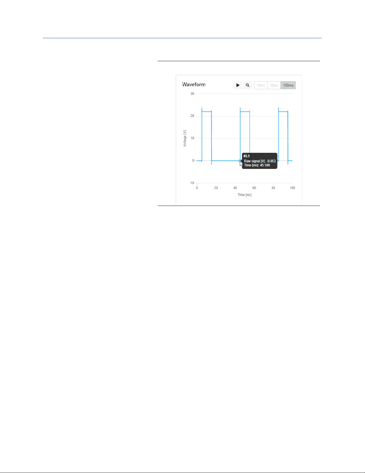
Configure the AMS Asset Monitor Operating Manual
June 2022 MHM-97924-PBF
Figure 6-10: End of the period (Point 2)
The time of one period is the time at end of the period (Point 2)
minus the time at the beginning of the period (Point 1).
Time of one period = Point 2 - Point 1
Example:
45.1 ms - 5.1 ms = 40.0 ms
3. Note down the time of the period portion which is smaller than
or equal to 50%.
58 MHM-97924-PBF, Rev. 3.2
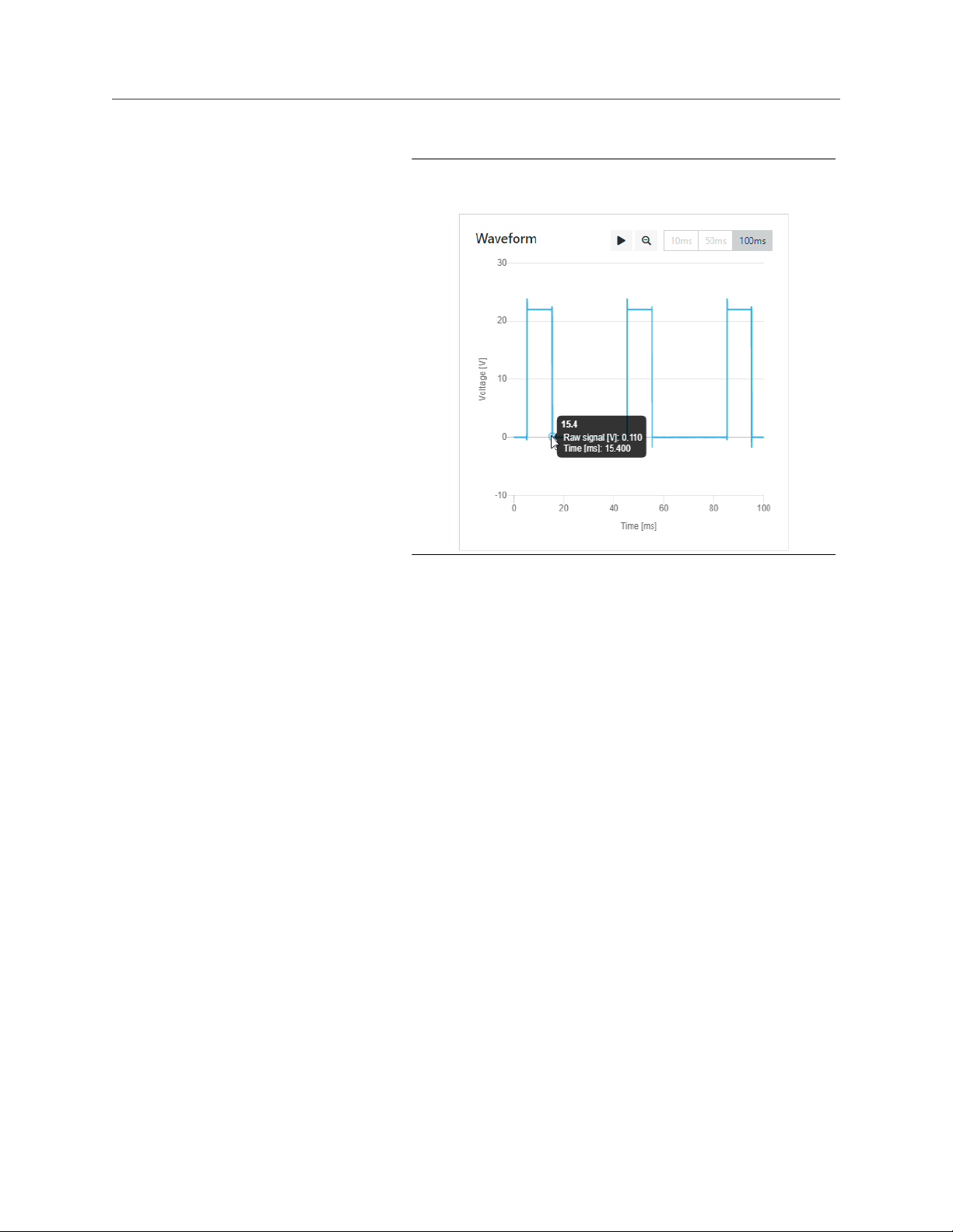
Operating Manual Configure the AMS Asset Monitor
MHM-97924-PBF June 2022
Figure 6-11: End of the period portion smaller than or equal
to 50% (Point 3)
Measurement
mode
The time of one period portion smaller than or equal to 50% is
the time at end of the period (Point 3) minus the time at the
beginning of the period (Point 1).
Time of the period portion
= Point 3 - Point 1
<50%
Example:
15.4 ms - 5.1 ms = 10.3 ms
4. Calculate the symmetry.
Symmetry = Period portion
* 100% / Period
<50%
Example:
Symmetry = 10.3 ms * 100% / 40 ms = 25.75 %
Round down the result to the next smaller number as only
integer values can be entered.
5. Enter the calculated symmetry.
AMS Asset Monitor Web Interface checks the entries of the
parameters Number of teeth, Symmetry, and Maximum speed on
plausibility. The entry fields are red framed if the entries do not meet
the minimum requirements of the VI Tach CHARM. In this case select
another wheel as a source for the measurement.
This entry field is available if Wheel type → Multi tooth is selected.
Select a measurement mode suitable to your machine.
• Standard
This mode is suitable for most of the machines. The speed value is
refreshed every 104 to 216 ms, regardless of the entered
maximum machine speed (Maximum speed). A disadvantage of
MHM-97924-PBF, Rev. 3.2 59

Configure the AMS Asset Monitor Operating Manual
June 2022 MHM-97924-PBF
this mode is a possibly more unstable indication of the speed
value. This is caused by varying measuring results during a rotation
because of shaft vibrations and mechanical deviations of tooth
gaps and sizes.
• Standard + stabilization (max. speed < 720; increased update
time)
This mode is like Standard but uses higher refresh times at
maximum machine speeds (Maximum speed) below 720 rpm to
increase stability of the speed value.
• On full rotations (eliminates speed invariance within one
rotation)
Select this mode if the machine, on which the speed is measured,
has high vibrations. The speed value is refreshed after every
rotation.
Maximum
speed
Trigger
threshold limits
Enter the maximum speed of the machine.
Enter the upper and lower trigger threshold limit for the detection of
the signal pulses. The limits must be within the peak-to-peak signal.
Use the trend display Waveform in the status overview of the VI Tach
CHARM (see Status overview – CHARM) to define the trigger threshold
limits based on the input signal.
1. Use the time scaling buttons to adjust the view of the waveform
so that at least one period of the input signal is visible. Click
Stop to stop the continuously writing of the trend. Example
with a signal including DC level of an eddy current measuring
chain (Converter) connected to the VI Tach CHARM:
60 MHM-97924-PBF, Rev. 3.2

Operating Manual Configure the AMS Asset Monitor
MHM-97924-PBF June 2022
Figure 6-12: Waveform of a negative input signal
2. Move the cursor over the waveform. The raw signal in volt and
the time in millisecond are displayed at the cursor position.
Note down the voltage of the lower peak of the signal
amplitude (upper peak with a negative input signal). This
voltage is also the DC level if using sensors that generate a
signal with a DC level. Example:
Figure 6-13: Upper voltage and DC level of a negative input
signal
MHM-97924-PBF, Rev. 3.2 61
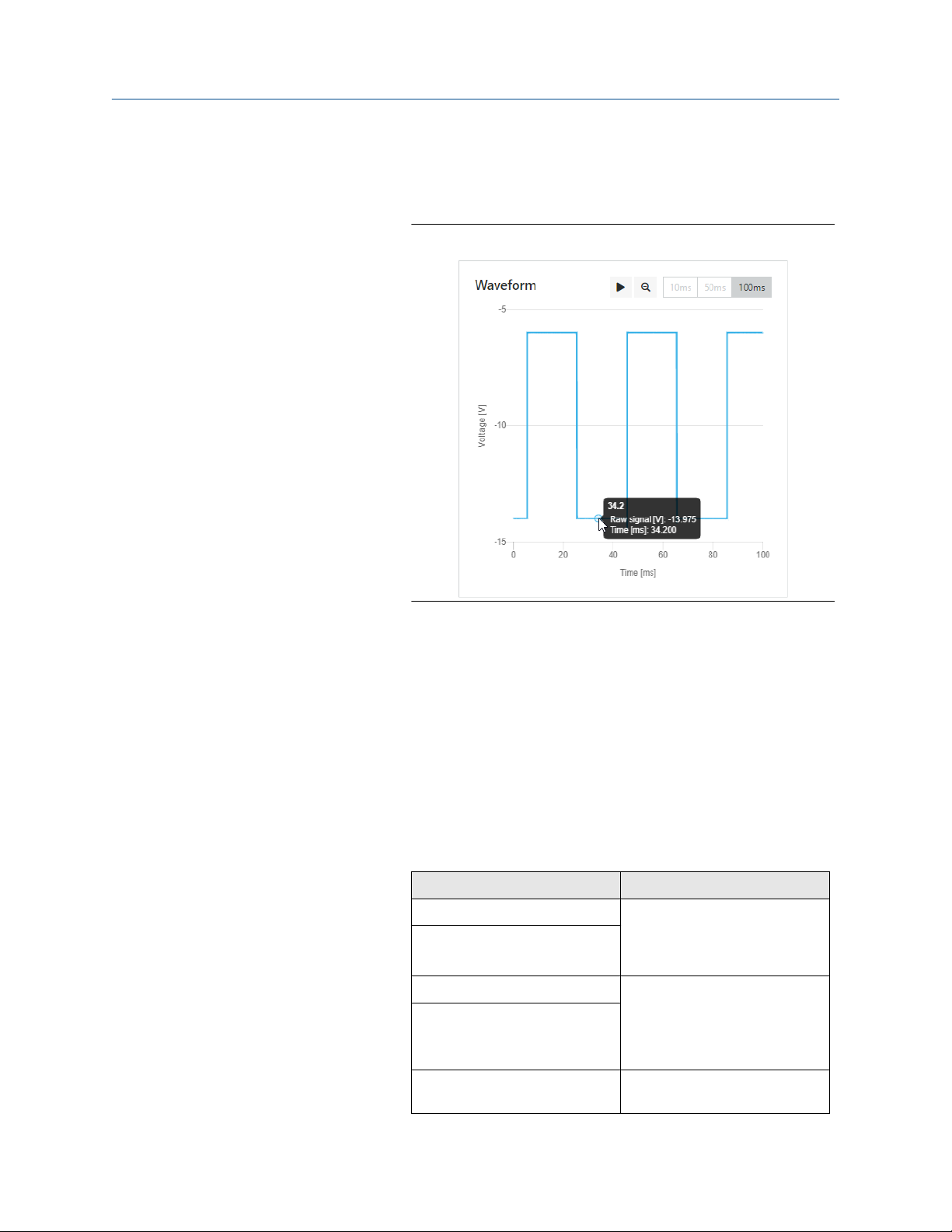
Configure the AMS Asset Monitor Operating Manual
June 2022 MHM-97924-PBF
3. Move the cursor over the waveform. Note down the voltage of
the upper peak of the signal amplitude (lower peak with a
negative input signal). Example:
Figure 6-14: Lower voltage of a negative input signal
4. Determine the signal amplitude (peak-to-peak voltage).
Positive input signal: U
Negative input signal: U
Amplitude
= Lower voltage - Upper Voltage
Amplitude
= |Upper voltage| - |Lower
Voltage|
Example for a negative sensor signal:
U
Amplitude
= |-14.0 V| - |-6.0 V| = 8 V peak-to-peak
5. Calculate the trigger threshold limits. Select a formula from the
table. Experience has shown that values 3/8 and 5/8 of the
signal amplitude provide suitable trigger threshold limits.
Table 6-4: Formulas based on the input signal for
calculating trigger level thresholds
Formula Use case
LTT = (-5*U
UTT = (-3*U
LTT = 3*U
UTT = 5*U
LTT = (3*U
Amplitude
Amplitude
Amplitude
Amplitude
Amplitude
/8)+U
/8)+U
DC Level
DC Level
Use these formulas if the sensor
signal is negative and contains a
DC level. Such as a signal from an
eddy current measuring chain.
/8 Use these formulas if the sensor
/8
signal is positive and does not
contain a DC level. Such as a
signal from a Hall-effect sensor
or a magnetic pickup (MPU).
/8)+U
DC Level
Use these formulas if the sensor
signal is positive and contains a
62 MHM-97924-PBF, Rev. 3.2
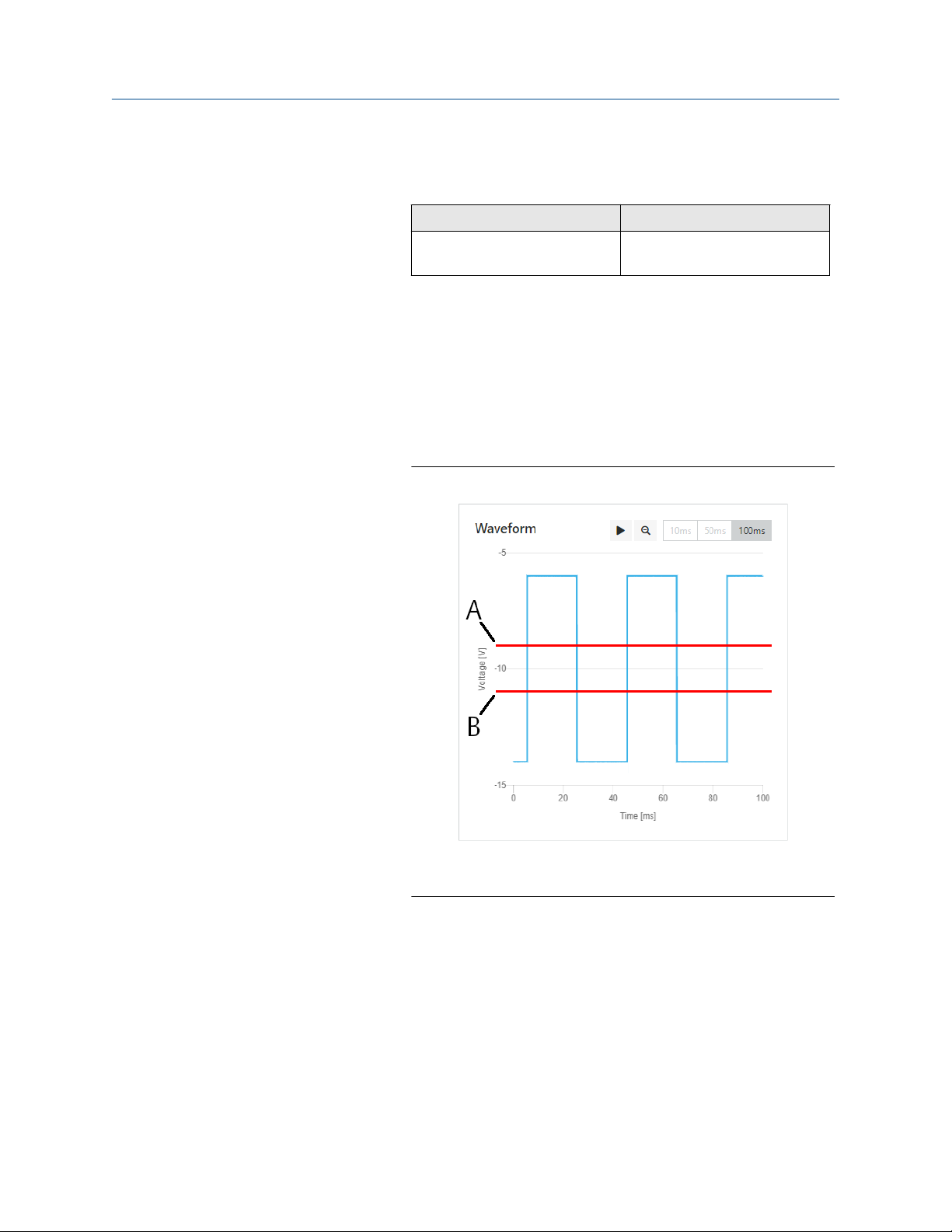
Operating Manual Configure the AMS Asset Monitor
MHM-97924-PBF June 2022
Table 6-4: Formulas based on the input signal for
calculating trigger level thresholds
Formula Use case
(continued)
UTT = 5*U
Amplitude
/8+U
DC Level
DC level. Such as a signal from a
Hall-effect sensor with DC offset.
LTT: Lower trigger threshold limit
UTT: Upper trigger threshold limit
U
Amplitude
U
DC Level
: Amplitude of the input signal (peak-to-peak)
: DC offset, such as the sensor adjustment level over a
tooth if using an eddy current measuring chain.
Example for a negative sensor signal:
LTT = (-5 * 8 V / 8) + (-6 V) = -11 V
UTT = (-3 * 8 V / 8) + (-6 V) = - 9 V
Figure 6-15: Example: trigger threshold limits
A. Upper trigger threshold limit: - 9 V
B. Lower trigger threshold limit: - 11 V
6. Enter the calculated trigger threshold limits.
Zero speed
detection time
Enter a time for the zero speed detection. The entered time must
elapse after the last detected pulse at the signal input before zero
speed is indicated. The entered time must be longer than the time
between two detected pulses with the machine running. The zero
speed indication is reset as soon as the next pulse is detected at the
signal input.
Display range
Enter a lower limit value and an upper limit value to define a range for
displaying the measured value.
MHM-97924-PBF, Rev. 3.2 63

Configure the AMS Asset Monitor Operating Manual
June 2022 MHM-97924-PBF
VI Voltage CHARM
Measurement
type
Unit
Evaluation
Select a measuring type in accordance to the connected signal source.
The connected signal source must meet the electrical input
requirements of the VI Voltage CHARM.
• Select Displacement if an AC voltage signal source is connected
that provides a signal proportional to a dynamic displacement
value.
• Select Velocity if an AC voltage signal source is connected that
provides a signal proportional to a velocity value.
• Select Voltage if a signal source is connected that provides a signal
proportional to an AC input voltage.
Select a unit in accordance to the technical data of the connected
signal source. The available options depend on the selected
measurement type. It is not necessary that the unit aligns to the
selected system of units configured for the logged in user. The unit is
automatically converted to the user's system of units for the following
parameters.
Select the required signal evaluation from the drop-down list. Which
evaluations are available depend on the selected measurement type.
Table 6-5: Selectable evaluations
Displacement Velocity Voltage
Sensitivity
Evaluation filter
DC bias range
Displacement 0-P Velocity 0-P Voltage 0-P
Displacement P-P Velocity P-P Voltage P-P
Displacement RMS Velocity RMS Voltage RMS
Enter the sensitivity of the connected signal source.
Select a bandpass filter in accordance to your measurement
application.
Enter a lower limit value and an upper limit value to define a DC bias
range for the CHARM supervision. See technical data of the connected
signal source for the typical bias voltage. The CHARM's supervision
function indicate a not OK status if the DC part of the input voltage is
out of the defined OK range.
If the input voltage returns to the OK range the not OK status is reset.
64 MHM-97924-PBF, Rev. 3.2

Operating Manual Configure the AMS Asset Monitor
MHM-97924-PBF June 2022
Figure 6-16: DC bias range
A. DC voltage range
B. Upper limit value
C. Bias (DC offset)
D. Lower limit value
E. Input signal OK range
F. Input signal not OK range
G. Time
Measurement
range (±)
Display range
RTD CHARM
Functionality
Enter a limit value to define a ± OK range for the CHARM supervision.
See technical data of the connected signal source for the measuring
range. The CHARM's supervision function indicates a not OK status if
the measuring values is out of the defined OK range.
If the measurement value returns to the OK range the not OK status
is reset.
Enter a lower limit value and an upper limit value to define a range
for displaying the measured value.
Select the type of the connected RTD temperature sensor from the
drop-down list.
• Resistance RTD Input
• User defined RTD Input
If the connected RTD sensor is not listed use this option to define
the sensor. Parameters for entering temperature range and
coefficients appears if this functionality is selected.
• Pt 100 RTD Input
Platinum temperature sensor, 0°C at 100 Ω
MHM-97924-PBF, Rev. 3.2 65

Configure the AMS Asset Monitor Operating Manual
June 2022 MHM-97924-PBF
• Pt 200 RTD Input
Platinum temperature sensor, 0°C at 200 Ω
• Pt 500 RTD Input
Platinum temperature sensor, 0°C at 500 Ω
• Pt 1000 RTD Input
Platinum temperature sensor, 0°C at 1000 Ω
• Ni 100 RTD Input
Nickel temperature sensor, 0°C at 100 Ω
• Ni 120 RTD Input
Nickel temperature sensor, 0°C at 120 Ω
• Ni 200 RTD Input
Nickel temperature sensor, 0°C at 200 Ω
• Ni 500 RTD Input
Nickel temperature sensor, 0°C at 500 Ω
• Ni 1000 RTD Input
Nickel temperature sensor, 0°C at 1000 Ω
Number of wires
Compensation
Antialiasing filter
Temperature
range
• CU 10 RTD Input
Copper temperature sensor, 0°C at 10 Ω
Select the number of wires in accordance to the sensor connection.
• 2 wire
• 3 wire
• 4 wire
Only if Number of wires → 2 Wire is selected.
Enter the resistance of the length of the wires in ohms to
compensate a temperature offset caused by the two wire connection
of the sensor.
Select a period of time from the drop-down list in accordance to your
measurement application or select Disabled to disable the filter.
The signal filtering is made within the CHARM. Select a short period
of control for highly dynamic input signals where also signal peaks
must be detected. Use shorter periods of control for critical
measurements to ensure that no signal parts are missed. For slow
changing input signals or to avoid detection of signal peaks select a
longer period of control.
Only if Functionality → User defined RTD Input is selected.
Enter the lower temperature of the temperature range in the left
input field and the upper temperature of the temperature range in
the right input field.
Alpha coefficient
66 MHM-97924-PBF, Rev. 3.2
Only if Functionality → User defined RTD Input is selected.

Operating Manual Configure the AMS Asset Monitor
MHM-97924-PBF June 2022
Enter the alpha coefficient. See documentation provided with your
RTD sensor for the coefficient.
Beta coefficient
Delta coefficient
Display range
TC CHARM
Functionality
Only if Functionality → User defined RTD Input is selected.
Enter the beta coefficient. See documentation provided with your
RTD sensor for the coefficient.
Only if Functionality → User defined RTD Input is selected.
Enter the delta coefficient. See documentation provided with your
RTD sensor for the coefficient.
Enter a lower limit value and an upper limit value to define a range for
displaying the measured temperature.
Select the type of the connected thermocouple temperature sensor or
voltage input range from the drop-down list.
• Uncharacterized Thermocouple Input
The absolute value of the voltage at the screw terminals is
measured. The voltage is uncompensated for temperature.
Operating range: ±100 mV
• Type B Thermocouple Input
Material: Platinum-Rhodium (Pt30Rh) - Platinum-Rhodium (Pt6Rh)
Operating range: 250 to 1820°C
• Type E Thermocouple Input
Material: Nickel-Chromium – Copper-Nickel
Operating range: -200 to 1000°C
• Type J Thermocouple Input
Material: Iron – Copper-Nickel
Operating range: -210 to 1200°C
• Type K Thermocouple Input
Material: Nickel-Chromium – Nickel-Aluminum
Operating range: -200 to 1372°C
• Type N Thermocouple Input
Material: Nickel-Chromium-Silicon – Nickel-Silicon
Operating range: -200 to 1300°C
• Type R Thermocouple Input
Platinum-Rhodium (Pt12Rh) – Platinum (Pt)
Operating range: -50 to 1768°C
• Type S Thermocouple Input
Material: Platinum-Rhodium (Pt10Rh) – Platinum (Pt)
Operating range: -50 to 1768°C
• Type T Thermocouple Input
MHM-97924-PBF, Rev. 3.2 67

Configure the AMS Asset Monitor Operating Manual
June 2022 MHM-97924-PBF
Material: Copper – Copper-Nickel
Operating range: -200 to 400°C
• 20 Millivolt Input
Operating range: ±20 mV
• 50 Millivolt Input
Operating range: ±50 mV
• 100 Millivolt Input
Operating range: ±100 mV
Cold junction
temperature
source
Select a source for the cold junction compensation.
A thermocouple temperature sensor consists of two different materials
welded together. The weld point is called Hot junction (tip of the
thermocouple). A second point where two different materials are
connected together is the terminal block – connection of the
thermocouple wires to copper of the clamps. This point is called Cold
junction. A voltage – a thermoelectric voltage – is generated if there is a
temperature difference between the hot junction point and the colt
junction point. To measure the temperature at the hot junction (tip of
the thermocouple) the colt junction temperature must be known. This
procedure is called Cold junction compensation. The AMS Asset
Monitor provides two options for the cold junction compensation:
• Local Compensation, measurement of the cold junction
temperature with the RTD temperature sensor integrated into the
Thermocouple/mV Terminal Block.
• CHMx-yy (x: number of the address plug, yy: slot number),
measurement of the cold junction temperature with a RTD CHARM.
The temperature sensor connected to this CHARM must be installed
close to the cold junction of the TC measurement. All installed RTD
CHARMs are listed.
68 MHM-97924-PBF, Rev. 3.2

Operating Manual Configure the AMS Asset Monitor
MHM-97924-PBF June 2022
Figure 6-17: Thermocouple – simplified diagram
A. Regular copper wires
B. Terminal block, cold junction temperature T
0
C. Compensation wires (same material as the connected thermocouple)
D. Thermocouple, hot junction temperature T
1
Compensation
Use this parameter to add an offset (positive or negative) to the
measured temperature. This might be necessary if the temperature
of interest cannot be measured directly, but the temperature
difference between the required measuring point and the actual
measuring point is fix and known. Enter this temperature difference
here.
Antialiasing
filter
Select a period of time from the drop-down list in accordance to your
measurement application or select Disabled to disable the filter.
The signal filtering is made within the CHARM. Select a short period of
control for highly dynamic input signals where also signal peaks must
be detected. Use shorter periods of control for critical measurements
to ensure that no signal parts are missed. For slow changing input
signals or to avoid detection of signal peaks select a longer period of
control.
Display range
Enter a lower limit value and an upper limit value to define a range for
displaying the measured temperature.
24 V DO CHARM
Functionality
Select the function of the CHARM.
• Discrete Output
The CHARM drives the output to a discrete value written by the AMS
Asset Monitor and holds the output at that value. The output
immediately reflects the output value that was received. Upon
receiving a configuration that indicates a change from one type of
output to another, the output switches to the off state.
MHM-97924-PBF, Rev. 3.2 69

Configure the AMS Asset Monitor Operating Manual
June 2022 MHM-97924-PBF
• Momentary Output
The CHARM produces a momentary pulse by driving the output
active for a specific time period each time the AMS Asset Monitor
writes a value of TRUE (1, ON). Upon receiving a new pulse value,
the existing pulse is allowed to terminate normally before the new
value is written. Upon receiving a configuration that indicates a
change from one type of output to another, the output switches to
the off state.
• Continuous Pulse Output
The CHARM produces a continuous pulse by driving the channel
output value ON for a percentage of the specified time period.
Upon receiving a new on-time value (which is a percent of the pulse
period), the output of the channel stays on for that amount of time
and goes to the OFF state for the remainder of the pulse period. At
that time the channel receives a new on-time value from the
module.
Failure action
mode
Failure action
value
On time
Controls the behavior of the channel when the CHARM goes into failure
action condition due to lost communication with the system's
controller. Select an option:
• Hold last value
The channel holds the value at the start of the failure action
condition.
• Go to configured failure action value
The channel uses the configured failure action value (see Failure
action value).
Select the Boolean value the channel goes to when the CHARM goes
into failure action condition. This value is used only if Failure action
mode Go to configured failure action value is selected.
• Off (0)
• On (1)
Only if Functionality → Momentary or Continuous Pulse Output is
selected.
• Momentary: Enter the length of time (in milliseconds) that the
output is turned on when the CHARM's input value changes from 0
to 1.
• Continuous Pulse Output: Enter the length of time (in milliseconds)
that the output is turned on.
Initial on time
Only if Functionality → Continuous Pulse Output is selected.
Enter the percentage of the pulse period (see Pulse period) the
channel is on during initial download before any system actions. Set
Initial on time to zero for no pulse.
Pulse period
70 MHM-97924-PBF, Rev. 3.2
Only if Functionality → Continuous Pulse Output is selected.

Operating Manual Configure the AMS Asset Monitor
MHM-97924-PBF June 2022
Enter the length of time between pulses of the channel, from 2 to 200
milliseconds. The pulse period consists of output channel being ON for
a portion of the period (based on the configured On time value) and
OFF for the remainder of the period.
Initial value
Line fault
detection
Only if Functionality → Discrete Output is selected.
Select the Boolean value the channel goes to upon initial download
before any AMS Asset Monitor action.
• Off (0)
• On (1)
Place a checkmark in this box to enable the CHARM to detect an open
or shorted circuit. Once per second the current output state is changed
for testing. The test time does not exceed 200 μs (microsecond).
• Output state ON: The output is turned OFF and tested. The OFF
time does not exceed 200 μs.
• Output state OFF: The output us turned ON and tested. The ON
time does not exceed 200 μs.
Note
Do not connect the output with enabled line fault detection to a device
that is capable of sensing a change of state in 200 μs.
Note
Line fault detection is not compatible with significant capacitive
loading (cable + load > 30 nF) and must be disabled under these
conditions.
The line fault detection levels are:
• <50 Ω load for short circuit detection,
• 240 Ω to 10 kΩ load for the good status, and
• >20 kΩ load for open circuit detection.
24 V DI CHARM
Functionality
Debounce
filter
MHM-97924-PBF, Rev. 3.2 71
Select the function of the CHARM.
• Discrete Input
The CHARM reports the discrete value present at the channel.
• Pulse Count Input
The CHARM reports the number of discrete pulses detected at the
channel. Maximum input frequency is 10 kHz.
Only if Functionality → Discrete Input is selected.
Select a debounce filter.
• None

Configure the AMS Asset Monitor Operating Manual
June 2022 MHM-97924-PBF
No debounce filter is active. No effect on the input value. The input
state equals the raw state. If the system cannot obtain a reading for
the raw state in 10 samples, it sets bad status.
• Delay
The input state turns ON or OFF after the raw state has been ON or
OFF for at least the configured time duration (see Value).
Figure 6-18: Debounce filter – Delay
A. Raw state
B. Output state
C. Filter time
D. Duration > Filter time
E. Duration < Filter time
F. Duration < Filter time
G. Duration > Filter time
H. Time
• Glitch
The input state change is held for at least the configured time
duration (see Value). A change to the raw state during the hold
time causes the input state to response to the change after the hold
expires and then hold again for the configured time.
72 MHM-97924-PBF, Rev. 3.2

Operating Manual Configure the AMS Asset Monitor
MHM-97924-PBF June 2022
Figure 6-19: Debounce filter – Glitch
A. Raw state
B. Output state
C. Duration = Filter time
D. Time
• Average
The CHARM samples input 1000 times per second. When Average
is selected the counter is incremented or decremented once per
sample. When the input is True, the counter is incremented. When
the input is False, the counter is decremented. If the counter
decrements to zero, the output is set to False and the counter
ignores further decrements. If the counter increments up to the
threshold, the output is set to True and the counter ignores further
increments. If the counter is between zero and the threshold, the
output retains its previous state. The threshold determines the
amount of filtering: a threshold of one performs no filtering and a
threshold of N requires a signal to be present for N accumulated
samples before the output changes state (see Value).
Value
Only if a Debounce filter is selected.
Depending on the selected Debounce filter, enter a filter time or select
a counter.
Output filter
Only if Functionality → Discrete Input is selected.
Select an output filter.
• None
No effect on the output value. The output state equals the raw
state.
• Extend
The output state is held for the configured time duration (see
Value). The output state responds only to the most recent raw state
at the end of the configured hold time.
MHM-97924-PBF, Rev. 3.2 73
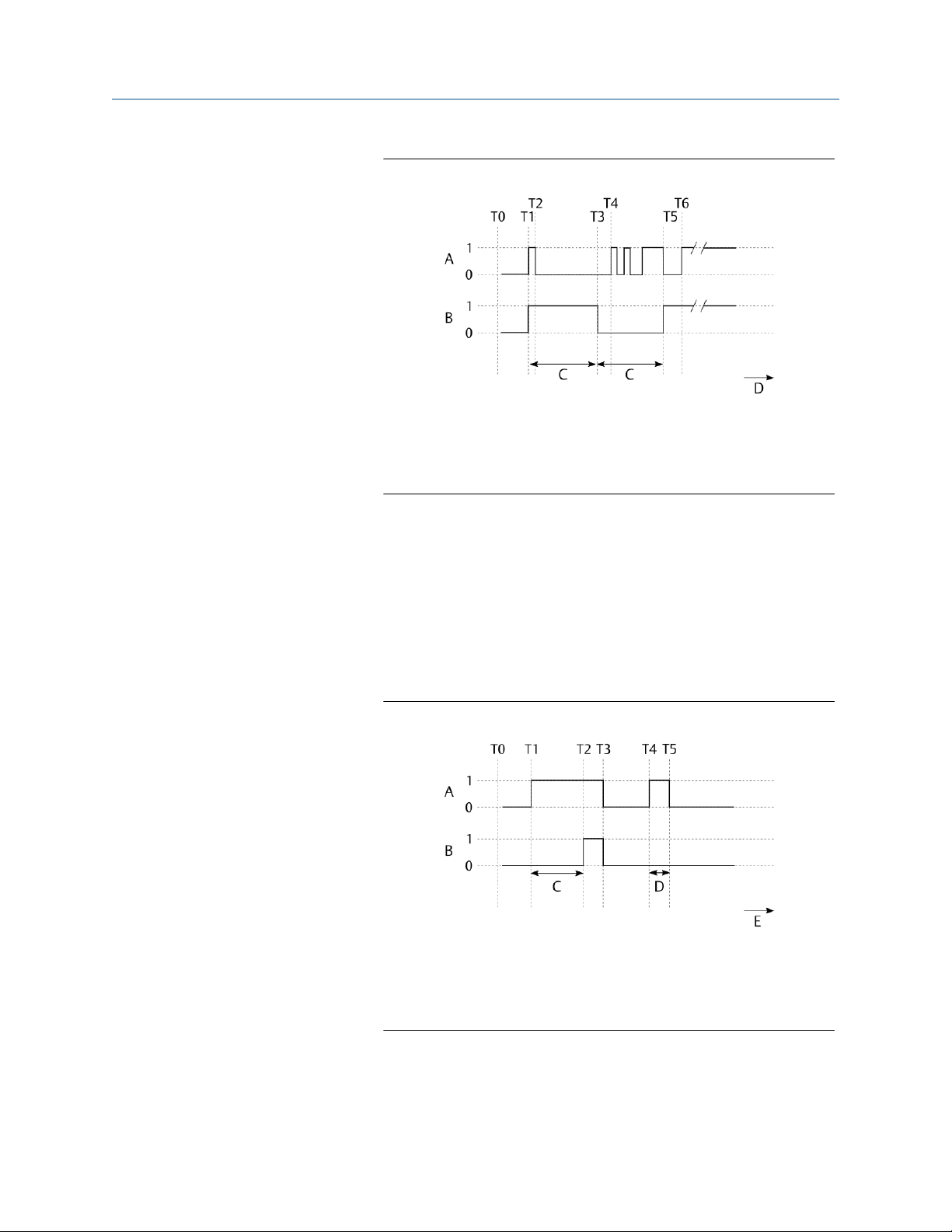
Configure the AMS Asset Monitor Operating Manual
June 2022 MHM-97924-PBF
Figure 6-20: Output filter – Extend
A. Raw state
B. Output state
C. Duration = Filter time
D. Time
• Delay
The output state is delayed by the configured filter time (see
Value). The delay affects the output on both changes from OFF to
ON and from ON to OFF. If the state changes but does not maintain
the state for greater than or equal to filter time, the output state
does not change. See Figure 6-18.
• Delay On
The output state turns ON after the raw state has been ON for at
least the configured time duration (see Value).
Figure 6-21: Output filter – Delay on
A. Raw state
B. Output state
C. Duration = Filter time
D. Duration < Filter time
• Delay Off
The output state turns Off after the raw state has been Off for at
least the configured time duration (see Value).
74 MHM-97924-PBF, Rev. 3.2
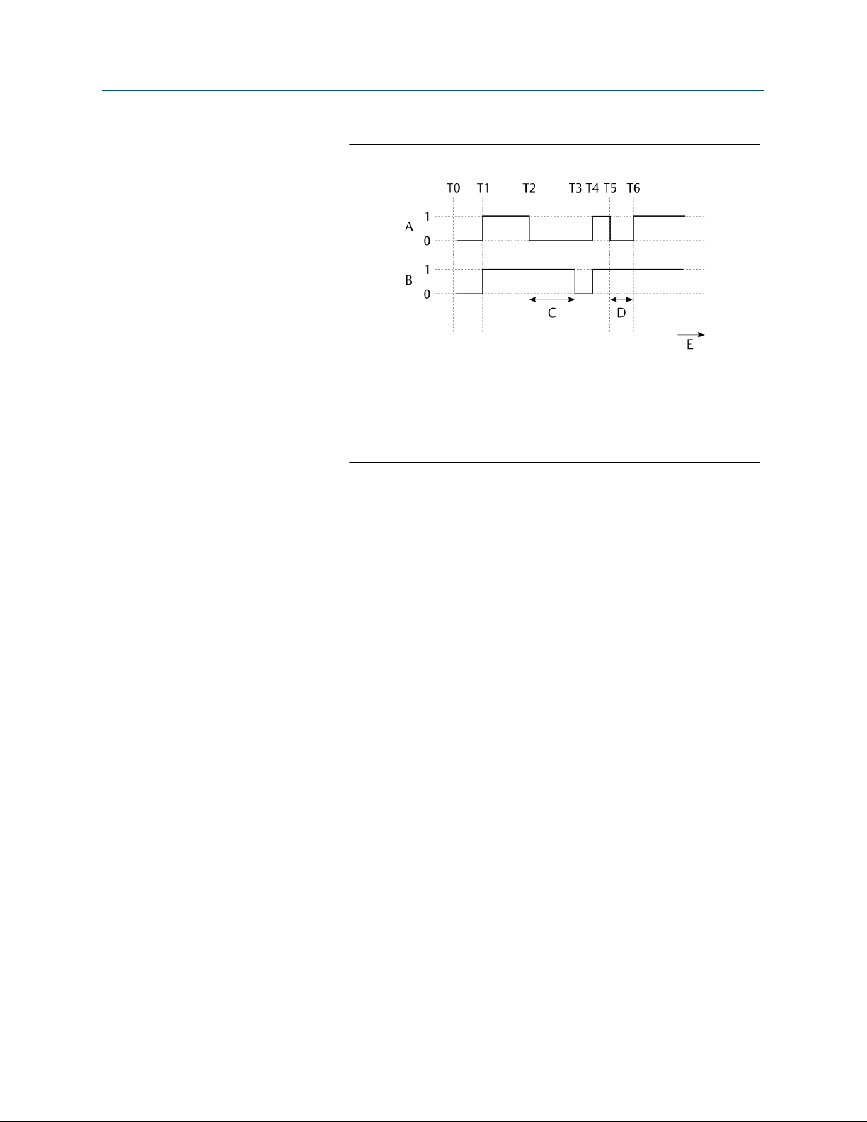
Operating Manual Configure the AMS Asset Monitor
MHM-97924-PBF June 2022
Figure 6-22: Output filter – Delay off
A. Raw state
B. Output state
C. Duration = Filter time
D. Duration < Filter time
E. Time
• Glitch
The input state change is held for at least the configured time
duration (see Value). A change to the raw state during the hold
time causes the input state to respond to the change after the hold
expires and then hold again for the configured time. See Figure
6-19.
• Settle
An output state change is held until a matching raw state is
maintained for the configured time duration (see Value). A change
in the raw state causes a change in the output state.
MHM-97924-PBF, Rev. 3.2 75

Configure the AMS Asset Monitor Operating Manual
June 2022 MHM-97924-PBF
Figure 6-23: Output filter – Settle
A. Raw state
B. Output state
C. Duration = Filter time
D. Duration < Filter time
E. Duration = Filter time
F. Duration < Filter time
G. Duration > Filter time
H. Duration > Filter time
I. Duration < Filter time
J. Time
Value
Modify input
Averaging
time
Line fault
detection
Display range
Only if an Output filter is selected.
Depending on the selected output filter, enter a filter time.
Only if Functionality → Discrete Input is selected.
Place a check mark in the box to invert the raw signal.
Only if Functionality → Pulse Count Input is selected.
Select an averaging time suitable for your application. A wrong
selection causes bouncing pulse count values.
Place a checkmark in the box to activate the detection of open and
short circuit. This fault detection requires external resistors added to
the input wiring. See AMS Asset Monitor Installation Guide
(MHM-97923-PBF) for details.
The Line fault detection levels are:
• <100 Ω load for short circuit detection,
• 400 Ω to 40 kΩ load for the good status, and
• >75 kΩ load for open circuit detection.
Enter a lower value and an upper value to define a range for displaying
the counted pulses. This parameter is only available if Pulse Count
Input is selected for Functionality.
76 MHM-97924-PBF, Rev. 3.2

Operating Manual Configure the AMS Asset Monitor
MHM-97924-PBF June 2022
4 to 20 mA AI CHARM
Functionality
Measurement
type
Select the function of the CHARM.
• Analog Input 0-20 mA
The assigned value is scaled on an input current range of 0 to 20
mA.
• Analog Input 4-20 mA
The assigned value is scaled on an input current range of 4 to 20
mA. Select this range if an input channel supervision is required.
Select a measurement type for the scaling.
• Acceleration
• Acoustic emission
• Current
• Displacement
• Mass flow rate
• Moisture in oil, saturation
• Moisture in oil, water activity
• Moisture in oil, water content
• Oil quality
• Pressure
Unit
Antialiasing
filter
Scaling
• Proportion
• Rotational speed
• Temperature
• Velocity
• Voltage
The input fields Unit and Scaling are available depending on the
selected measurement type.
Select a unit in accordance to the source of the input signal.
Depending on the selection, input fields for defining a scaling appears.
Select a period of time from the drop-down list in accordance to your
measurement application or select Disabled to disable the filter.
The signal filtering is made within the CHARM. Select a short period of
control for highly dynamic input signals where also signal peaks must
be detected. Use shorter periods of control for critical measurements
to ensure that no signal parts are missed. For slow changing input
signals or to avoid detection of signal peaks select a longer period of
control.
The current signal of a process value such as temperature or pressure
can be scaled on a defined range. Enter a lower limit and an upper limit
MHM-97924-PBF, Rev. 3.2 77
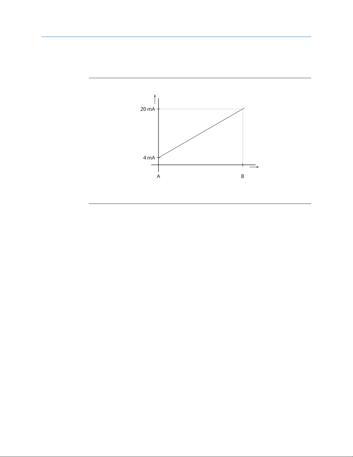
Configure the AMS Asset Monitor Operating Manual
June 2022 MHM-97924-PBF
value to define the scaling. See Figure 6-24 for an example where a 4 to
20 mA current input is scaled on a defined range.
Figure 6-24: Scaling example
A. Lower limit – assigned to 4 mA
B. Upper limit – assigned to 20 mA
Display range
Enter a lower limit value and an upper limit value to define a range for
displaying the measured value.
6.3 External data points
Recommended procedures – External data points describes procedures to create, change,
and delete a configuration of an external data point. Parameter description – External data
points describes the parameters to be configured.
6.3.1
Recommended procedures – External data points
First configuration – External data points
Procedure
1. Select External data points from the sidebar.
2. Click + New external data point.
The dialog for defining an external data point opens. Up to 50 external data points
can be defined.
3. Enter the parameters in accordance to the data to be imported to define the
external data point.
4. Click Save & Close to accept the entries.
A new external data point object appears on the overview page.
78 MHM-97924-PBF, Rev. 3.2
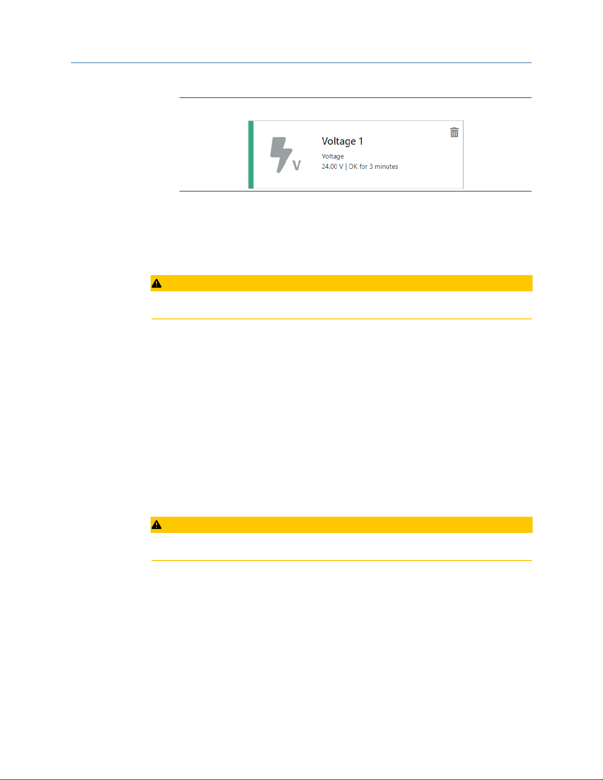
Operating Manual Configure the AMS Asset Monitor
MHM-97924-PBF June 2022
Figure 6-25: New external data point
The new external data point is automatically added to the OPC UA Server. To use
the new data point with the Modbus TCP communication add it to the holding
registers. See Holding registers.
Configuration change – External data point
CAUTION
Any work on the system may impair asset health monitoring and machine protection.
Procedure
1. Select External data points from the sidebar.
2. Click the external data point object to be changes to open the dialog to define the
data point.
• In the Tiles view, click on the external data point object to be changed to open
the configuration. See Tiles view – External data points.
• In the List view, click Configure in the column Action in the row of the external
data point to be configured. See List view – External data points.
3. Check the settings and change them according to your needs.
4. Click Save & Close to accept the entries.
Delete an external data point
CAUTION
Any work on the system may impair asset health monitoring and machine protection.
Procedure
1. Select External data point from the sidebar.
2. Delete the External data point.
• In the Tiles view, click the trash can icon in the data point object to be deleted to
remove the data point. See Tiles view – External data points.
• In the List view, click Delete in the column Action in the row of the external data
point to be deleted to remove the data point. See List view – External data
points.
MHM-97924-PBF, Rev. 3.2 79

Configure the AMS Asset Monitor Operating Manual
June 2022 MHM-97924-PBF
3. Confirm the confirmation prompt.
The external data point is automatically removed from the OPC UA tree and assets
in which it was used. Check the associated asset configuration and updated the
measuring location where the external data point was mapped to (see Source
mapping). An external data point that was used for the Modbus communication is
not automatically removed from the Modbus Holding registers. Go to the Modbus
configuration and remove the deleted external data point (see Modbus TCP).
6.3.2 Parameter description – External data points
Basic
Enabled
Name
Description
Value
Measurement
type
Source unit
Place a checkmark in the box to enable the external data point.
Enter a name for the external data point. This entry is also used to build the
name for the OPC UA data point and the Modbus data point.
The external OPC UA data point Name consists of:
• Displayname
• Value
• EURange
• EngineeringUnit
The external Modbus data point Name has two Modbus registers:
• Externals.Name.Value
• Externals.Name.Displayname
Enter a description of the external data point.
Select a measurement type in accordance to the measured physical
value from the drop-down list.
Select a source unit in accordance to the technical data of the
connected source from the drop-down list. The available options
depend on the selected measurement type. It is not necessary that
the source unit aligns to the selected system of units configured for
the logged in user. The unit is automatically converted to the user's
system of units.
Timeout
Display
Display range
80 MHM-97924-PBF, Rev. 3.2
Enter a time in seconds to define a timeout for the supervision of the
external data point. The status of the external data point is set to
Critical if the external data point has not been refreshed within the
entered time.
Enter a lower limit value and an upper limit value to define a range for
displaying the measured value.

Operating Manual Configure the AMS Asset Monitor
MHM-97924-PBF June 2022
6.4 Predicates
Recommended procedures – Predicates describes the procedures to create, change, and
delete a configuration of a predicate. Parameter description – Predicates described the
parameters to be configured.
6.4.1 Recommended procedures – Predicates
First configuration – Predicates
Procedure
1. Select Predicates form the sidebar.
2. Click +New Predicate.
The dialog for defining a predicates opens. Up to 20 predicates can be defined.
3. Define the predicate.
4. Click Save & close to accept the entries.
A new predicate object appears on the overview page.
Figure 6-26: New predicate object
The new predicate can be used for assets and data collections.
Configuration change – Predicates
CAUTION
Any work on the system may impair asset health monitoring and machine protection.
Procedure
1. Select Predicates from the sidebar.
2. Click the predicate object to be changed to open the dialog to define the predicate.
• In the Tiles view, click on the predicate object to be changed to open the
configuration. See Tiles view – Predicates.
• In the List view, click Configure in the column Action in the row of the predicate
to be configured. See List view – Predicates.
3. Check the settings and change them according to your needs.
4. Click Save & Close to accept the entries.
MHM-97924-PBF, Rev. 3.2 81
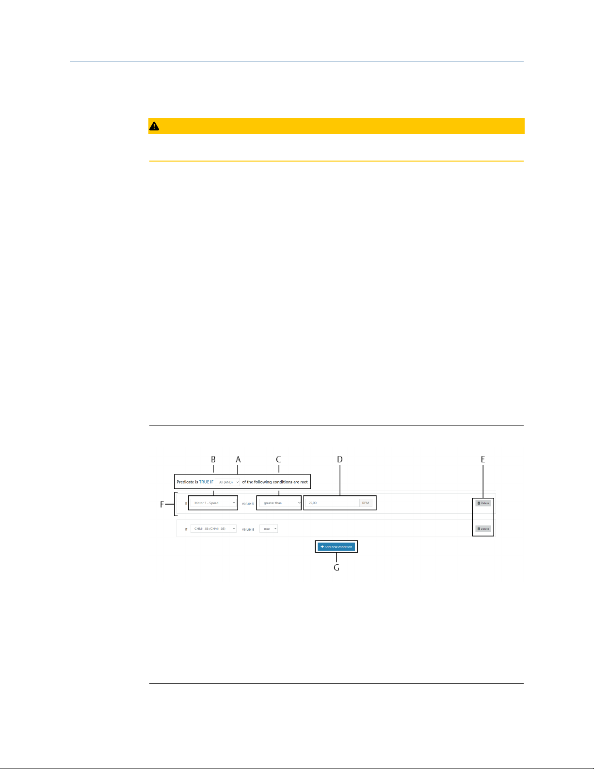
Configure the AMS Asset Monitor Operating Manual
June 2022 MHM-97924-PBF
Delete a predicate
CAUTION
Any work on the system may impair asset health monitoring and machine protection.
Procedure
1. Select Predicates from the sidebar.
2. Delete the predicate.
• In the Tiles view, click the trash can icon in the predicate object to be deleted to
remove the predicate. See Tiles view – Predicates.
• In the List view, click Delete in the column Action in the row of the predicate to
be deleted to remove the predicate. See List view – Predicates.
3. Confirm the confirmation prompt.
The predicate is removed from the system. Data collections and assets where the
predicate to be deleted is used continue to work without the predicate.
6.4.2
Parameter description – Predicates
Enabled
Name
Description
Figure 6-27: Condition configuration
A. Execution condition
B. Data source selection
C. Limit condition
D. Limit value
E. Button to delete a condition
F. Condition
G. Button + Add new condition
Place a checkmark in the box to enable the predicate.
Enter a name for the predicate.
Enter a short description of the predicate.
82 MHM-97924-PBF, Rev. 3.2

Operating Manual Configure the AMS Asset Monitor
MHM-97924-PBF June 2022
TRUE IF
+Add a new
condition
Select when the predicate is TRUE.
• Any (OR)
One or more of the defined conditions has been fulfilled.
• All (AND)
All defined conditions have been fulfilled.
Click +Add a new condition to add a new row for defining a predicate
condition.
Complete the new condition.
1. Select the data source. The available sources depend on the
configuration of the AMS Asset Monitor and can be an asset, a
CHARM, an external data point, or another predicate.
2. Select the limit condition.
• greater than
• greater than OR equal
• less than
• less than OR equal
• between (> min AND <= max)
• not between (<= min OR > max)
• TRUE
• FALSE
6
6
6.5 Assets
Typical measuring points and available rules are described for each asset type.
Recommended procedure – Assets describes procedures to create, change, and delete a
configuration. Parameter description – Assets describes the parameters of all assets.
6.5.1
6
For sources that provide a logical state.
General
For a proper health detection, sensors must be arranged on the equipment in a certain
way. The knowledge about the sensor arrangement is also necessary for the asset
configuration.
3. Enter a limit value if a sources is selected that provides a value. Two
entry field are available if between or not between is selected for
the limit condition.
To delete a condition, click the trash can icon at the end of the row to be
deleted.
MHM-97924-PBF, Rev. 3.2 83

Configure the AMS Asset Monitor Operating Manual
June 2022 MHM-97924-PBF
Note
The more measuring points are equipped, the more accurate is the health calculation of
the asset.
General recommendations:
• Use a point distribution that allows some horizontal, vertical, and axial inputs to get a
good overview of both the equipment's health and the equipment's general
movement.
• A radial measurement is recommended to evaluate balance and alignment.
• Generally measure radial vibration in horizontal direction because of the gravity load of
the measurement in vertical direction.
• For a good PeakVue and PeakVue Plus reading, place the sensor near the bearing load
zone.
• Select measuring points in accordance to your measuring task.
Some assets such as the Heat exchanger – shell & tube, counter-current and the
Hydrocarbon pump – centrifugal, overhung require input signals other than of vibration
sensors such as pressure, flow, and temperature sensors. See Table 6-6 for sensor types
and CHARMs or external data points required for the measurements.
Table 6-6: Sensor types and CHARMs or external data points required for the
measurements
Measurement Sensor type CHARM/External data point
Vibration Piezoelectric acceleration
sensor
Piezoelectric velocity sensor
Proximity probe and
converter1,
Speed Hall-effect sensor VI Tach CHARM
Passive magnetic pickup
Proximity probe and converter
Sensor that provides a scaled
current signal (0 to 20 mA or 4
to 20 mA)
Sensor that provides pulses
countable by the CHARM
Signal source that provides the
required data
Temperature Thermocouple Thermocouple/mV input
2
VI Piezo CHARM
VI Voltage CHARM
2
AI 4 to 20 mA CHARM
DI 24 V DC Low-Side Sens
CHARM
External data point
CHARM
RTD sensor RTD CHARM
Sensor that provides a scaled
current signal (0 to 20 mA or 4
to 20 mA)
84 MHM-97924-PBF, Rev. 3.2
AI 4 to 20 mA CHARM

Operating Manual Configure the AMS Asset Monitor
MHM-97924-PBF June 2022
Table 6-6: Sensor types and CHARMs or external data points required for the
measurements
Measurement Sensor type CHARM/External data point
(continued)
Signal source that provides the
required data
Motor current Sensor that provides a scaled
Oil quality
Flow turbulence
Suction pressure
Discharge pressure
Seal pressure
Seal level
Hydrocarbon leak
Flow
Differential pressure
1
For measurement of relative shaft vibration.
2
Requires an external voltage supply.
current signal (0 to 20 mA or 4
to 20 mA) or a signal source
that provides the required data
for the external data point
External data point
AI 4 to 20 mA CHARM or an
external data point
Note
The measuring signal used for the rules calculation is not influenced by the signal
evaluation and evaluation filters set in the CHRAM configuration.
Note
For installation and operation instructions of the used sensors see related documents.
The following chapters describe for each asset type the typical measurement points, the
available rules, and the minimum required CHARMs for the rules. It is not mandatory to
install sensors at each shown measuring point but ensure that the minimum requirements
of the used rules are fulfilled, otherwise the rules cannot be calculated.
6.5.2
Fan – axial, direct motor drive
Asset consisting of a combination of fan and electric motor. The fan is directly connected
to the motor without any gearbox in between.
MHM-97924-PBF, Rev. 3.2 85

Configure the AMS Asset Monitor Operating Manual
June 2022 MHM-97924-PBF
Typical measuring points
Figure 6-28: Typical measuring points
One bearing vibration measurement with a piezoelectric accelerometer on each bearing
of the asset is the recommended measurement.
Table 6-7: Typical measuring points
Position Measuring point
Description Abbreviation
1 Speed FSPD
2 Inboard horizontal vibration FIH
Inboard vertical vibration FIV
Inboard axial vibration FIA
Inboard X vibration FIX
Inboard Y vibration FIY
Inboard temperature FIT
3 Outboard horizontal vibration FOH
Outboard vertical vibration FOV
Outboard axial vibration FOA
Outboard X vibration FOX
Outboard Y vibration FOY
Outboard temperature FOT
4 Winding 1 temperature FW1T
Winding 2 temperature FW2T
Winding 3 temperature FW3T
Motor current FMC
86 MHM-97924-PBF, Rev. 3.2

Operating Manual Configure the AMS Asset Monitor
MHM-97924-PBF June 2022
Table 6-7: Typical measuring points
(continued)
Position Measuring point
Description Abbreviation
5 Auxiliary AUX
Available rules
Table 6-8 lists the selectable rules and their available input signals for the fan – axial, direct
motor drive asset.
Table 6-8: Fan – axial, direct motor drive
Rule Available input signals
CHARM Sensor Measuring
Uneven air gap VI Piezo CHARM Accelerometer or
piezo electric
velocity sensor
2
Balance
VI Piezo CHARM Accelerometer or
piezo electric
velocity sensor
VI Voltage
CHARM
Eddy current
measuring chain
1
points
FIH, FIV, FIA,FOH,
FOV, or FOA
FIH, FIV, FIA,FOH,
FOV, or FOA
FIX, FIY, FOX, or
FOY
Configuration
Bearing (using
VI Piezo CHARM Accelerometer FIH, FIV, FIA,FOH,
PeakVue Plus)
Blade pass VI Piezo CHARM Accelerometer or
piezo electric
velocity sensor
Looseness VI Piezo CHARM Accelerometer or
piezo electric
velocity sensor
Lubrication (using
VI Piezo CHARM Accelerometer FIH, FIV, FIA,FOH,
PeakVue Plus)
Oil whirl VI Voltage
CHARM
Flow turbulence –
2
fan
VI Piezo CHARM Accelerometer or
Eddy current
measuring chain
piezo electric
velocity sensor
VI Voltage
CHARM
Eddy current
measuring chain
FOV, or FOA
FIH, FIV, FIA,FOH,
FOV, or FOA
FIH, FIV, FIA,FOH,
FOV, or FOA
FOV, or FOA
FIX, FIY, FOX, or
FOY
FIH, FIV, FIA,FOH,
FOV, or FOA
FIX, FIY, FOX, or
FOY
Configured
bearings (see
Bearings, Shaft 1,
or Shaft 2)
Configured
bearing clearance
(see Bearings,
Shaft 1, or Shaft
2)
MHM-97924-PBF, Rev. 3.2 87
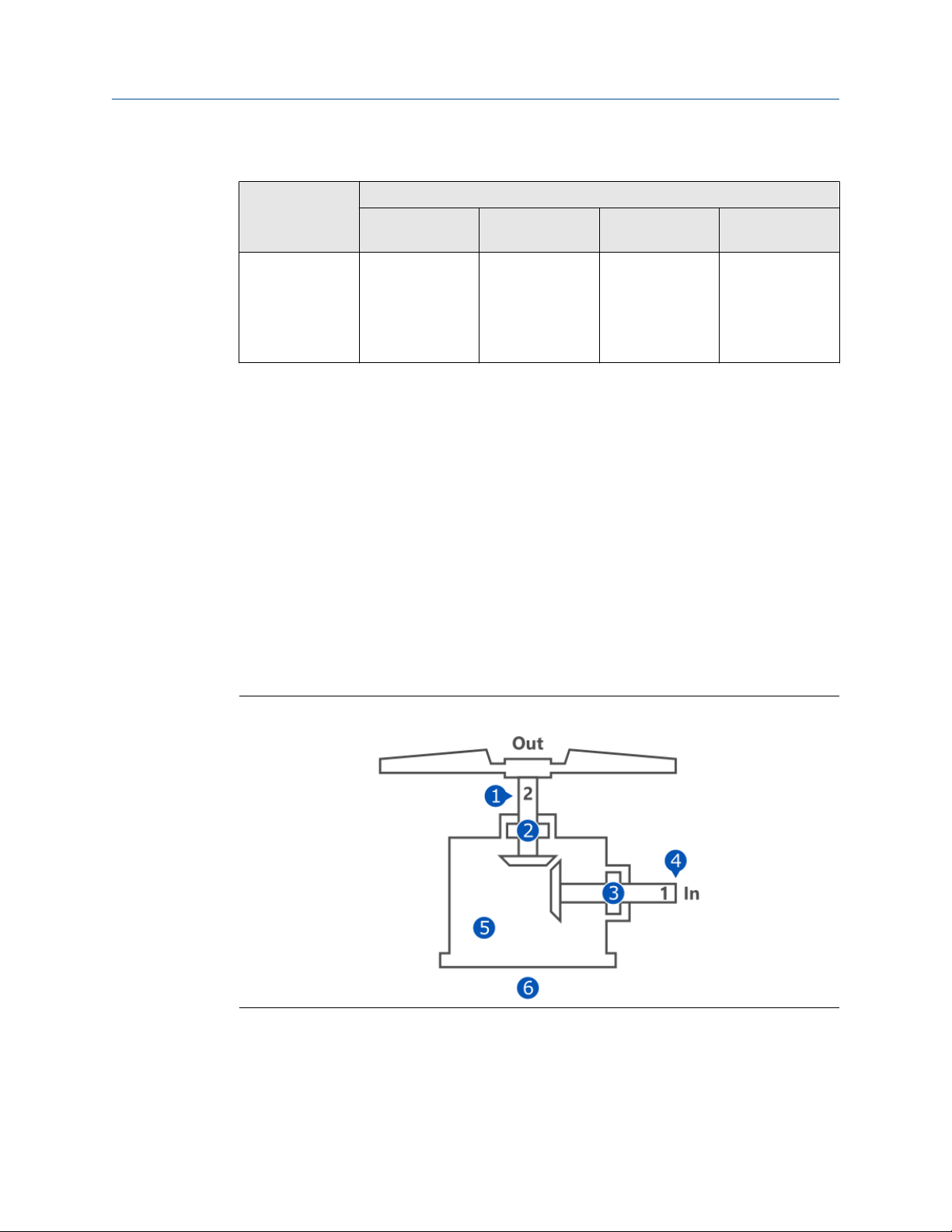
Configure the AMS Asset Monitor Operating Manual
June 2022 MHM-97924-PBF
6.5.3
Table 6-8: Fan – axial, direct motor drive
Rule Available input signals
CHARM Sensor Measuring
3
All rules
1
A single measuring point is sufficient to activate the rule.
2
One of the listed CHARMs is sufficient for the rule.
3
Actual rpm input is recommended.
4
Requires an external voltage supply.
VI Tach CHARM
(optionally 24 V
DI CHARM, 4 to
20 mA AI CHARM,
or External data
point)
(continued)
Passive magnetic
pickup, Hall-effect
sensor, or
Proximity probe
and converter
4
1
points
FSPD Accurate name
Configuration
plate speed of the
asset is always
required
At least one valid vibration sensor (connected and working properly) is needed to activate
a rule. The use of multiple sensors and vibration measuring points helps significantly to
detect asset condition deterioration and is recommended. The rules can work with
configured nominal asset speed (Running speed), but the monitoring of the actual rotor
speed with a VI Tach CHARM is recommended.
Fan – axial, gearbox drive
Asset consisting of a combination of fan and gearbox where the fan is directly connected
to a single reduction gearbox.
Typical measuring points
Figure 6-29: Typical measuring points
One bearing vibration measurement with a piezoelectric accelerometer on each bearing
of the asset is the recommended measurement.
88 MHM-97924-PBF, Rev. 3.2

Operating Manual Configure the AMS Asset Monitor
MHM-97924-PBF June 2022
Table 6-9: Typical measuring points
Position Measuring point
Description Abbreviation
1 Shaft 2 speed F2SPD
2 Shaft 2 outboard horizontal vibration F2OH
Shaft 2 outboard vertical vibration F2OV
Shaft 2 outboard axial vibration F2OA
Shaft 2 outboard X vibration F2OX
Shaft 2 outboard Y vibration F2OY
Shaft 2 outboard temperature F2OT
3 Shaft 1 inboard horizontal vibration F1IH
Shaft 1 inboard vertical vibration F1IV
Shaft 1 inboard axial vibration F1IA
Shaft 1 inboard X vibration F1IX
Shaft 1 inboard Y vibration F1IY
Shaft 1 inboard temperature F1IT
4 Shaft 1 speed F1SPD
5 Oil quality FOQ
6 Auxiliary AUX
Available rules
Table 6-10 lists the selectable rules and their available input signals for the fan – axial,
gearbox drive asset.
Table 6-10: Fan – axial, gearbox drive
Rule Available input signals
CHARM Sensor Measuring
Alignment VI Piezo CHARM Accelerometer or
piezo electric
velocity sensor
Balance
VI Voltage
CHARM
2
VI Piezo CHARM Accelerometer or
Eddy current
measuring chain
piezo electric
velocity sensor
1
points
F1IH, F1IV, F1IA,
F2OH, F2OV, or
F2OA
F1IX, F1IY, F2OX,
or F2OY
F1IH, F1IV, F1IA,
F2OH, F2OV, or
F2OA
Configuration
Only shaft 1 (In),
see Figure 6-29
VI Voltage
CHARM
MHM-97924-PBF, Rev. 3.2 89
Eddy current
measuring chain
F1IX, F1IY, F2OX,
or F2OY

Configure the AMS Asset Monitor Operating Manual
June 2022 MHM-97924-PBF
Table 6-10: Fan – axial, gearbox drive
(continued)
Rule Available input signals
CHARM Sensor Measuring
Bearing (using
VI Piezo CHARM Accelerometer F1IH, F1IV, F1IA,
PeakVue Plus)
Blade pass VI Piezo CHARM Accelerometer or
piezo electric
velocity sensor
Tooth wear VI Piezo CHARM Accelerometer or
piezo electric
velocity sensor
Cracked or broken
tooth (using
PeakVue Plus,
VI Piezo CHARM Accelerometer or
piezo electric
velocity sensor
under
development)
Gear
misalignment
VI Piezo CHARM Accelerometer or
piezo electric
velocity sensor
1
points
F2OH, F2OV, or
F2OA
F1IH, F1IV, F1IA,
F2OH, F2OV, or
F2OA
F1IH, F1IV, F1IA,
F2OH, F2OV, or
F2OA
F1IH, F1IV, F1IA,
F2OH, F2OV, or
F2OA
F1IH, F1IV, F1IA,
F2OH, F2OV, or
F2OA
Configuration
Configured
bearings (see
Bearings, Shaft 1,
or Shaft 2)
Looseness VI Piezo CHARM Accelerometer or
piezo electric
velocity sensor
Lubrication (using
VI Piezo CHARM Accelerometer F1IH, F1IV, F1IA,
PeakVue Plus)
Oil whirl VI Voltage
CHARM
Flow turbulence –
2
fan
VI Piezo CHARM Accelerometer or
Eddy current
measuring chain
piezo electric
velocity sensor
All rules
VI Voltage
CHARM
3
VI Tach CHARM
(optionally 24 V
DI CHARM, 4 to
20 mA AI CHARM,
or External data
Eddy current
measuring chain
Passive magnetic
pickup, Hall-effect
sensor, or
Proximity probe
and converter
point)
1
A single measuring point is sufficient to activate the rule.
2
One of the listed CHARMs is sufficient for the rule.
3
Actual rpm input is recommended.
4
Requires an external voltage supply.
F1IH, F1IV, F1IA,
F2OH, F2OV, or
F2OA
F2OH, F2OV, or
F2OA
F1IX, F1IY, F2OX,
or F2OY
Configured
bearing clearance
(see Bearings,
Shaft 1, or Shaft
2)
F1IH, F1IV, F1IA,
F2OH, F2OV, or
F2OA
F1IX, F1IY, F2OX,
or F2OY
FSPD Accurate name
plate speed of the
asset is always
4
required
90 MHM-97924-PBF, Rev. 3.2

Operating Manual Configure the AMS Asset Monitor
MHM-97924-PBF June 2022
At least one valid vibration sensor (connected and working properly) is needed to activate
a rule. The use of multiple sensors and vibration measuring points helps significantly to
detect asset condition deterioration and is recommended. The rules can work with
configured nominal asset speed (Running speed), but the monitoring of the actual rotor
speed with a VI Tach CHARM is recommended.
6.5.4 Fan – centrifugal, center hung
Asset consisting of a fan with a rotating part mounted in the center of two bearings.
Typical measuring points
Figure 6-30: Typical measuring points
One bearing vibration measurement with a piezoelectric accelerometer on each bearing
of the asset is the recommended measurement.
Table 6-11: Typical measuring points
Position Measuring point
Description Abbreviation
1 Outboard horizontal vibration FOH
Outboard vertical vibration FOV
Outboard axial vibration FOA
Outboard X vibration FOX
Outboard Y vibration FOY
Outboard temperature FOT
2 Inboard horizontal vibration FIH
Inboard vertical vibration FIV
MHM-97924-PBF, Rev. 3.2 91

Configure the AMS Asset Monitor Operating Manual
June 2022 MHM-97924-PBF
Table 6-11: Typical measuring points
Position Measuring point
Description Abbreviation
Inboard axial vibration FIA
Inboard X vibration FIX
Inboard Y vibration FIY
Inboard temperature FIT
3 Speed FSPD
4 Auxiliary AUX
(continued)
Available rules
Table 6-12 lists the selectable rules and their available input signals for the fan centrifugal
– center hung asset.
Table 6-12: Fan centrifugal – center hung
Rule Available input signals
CHARM Sensor Measuring
Alignment VI Piezo CHARM Accelerometer or
piezo electric
velocity sensor
1
points
FIH, FIV, FIA, FOH,
FOV, or FOA
Configuration
VI Voltage
CHARM
2
Balance
Bearing (using
PeakVue Plus)
Blade pass VI Piezo CHARM Accelerometer or
Looseness VI Piezo CHARM Accelerometer or
Lubrication (using
PeakVue Plus)
VI Piezo CHARM Accelerometer or
VI Voltage
CHARM
VI Piezo CHARM Accelerometer FIH, FIV, FIA, FOH,
VI Piezo CHARM Accelerometer FIH, FIV, FIA, FOH,
Eddy current
measuring chain
piezo electric
velocity sensor
Eddy current
measuring chain
piezo electric
velocity sensor
piezo electric
velocity sensor
FIX, FIY, FOX, or
FOY
FIH, FIV, FIA, FOH,
FOV, or FOA
FIX, FIY, FOX, or
FOY
FOV, or FOA
FIH, FIV, FIA, FOH,
FOV, or FOA
FIH, FIV, FIA, FOH,
FOV, or FOA
FOV, or FOA
Configured
bearings (see
Bearings, Shaft 1,
or Shaft 2)
92 MHM-97924-PBF, Rev. 3.2

Operating Manual Configure the AMS Asset Monitor
MHM-97924-PBF June 2022
Table 6-12: Fan centrifugal – center hung
Rule Available input signals
CHARM Sensor Measuring
Oil whirl VI Voltage
CHARM
Flow turbulence –
2
fan
3
All rules
1
A single measuring point is sufficient to activate the rule.
2
One of the listed CHARMs is sufficient for the rule.
3
Actual rpm input is recommended.
4
Requires an external voltage supply.
VI Piezo CHARM Accelerometer or
VI Voltage
CHARM
VI Tach CHARM
(optionally 24 V
DI CHARM, 4 to
20 mA AI CHARM,
or External data
point)
Eddy current
measuring chain
piezo electric
velocity sensor
Eddy current
measuring chain
Passive magnetic
pickup, Hall-effect
sensor, or
Proximity probe
and converter
(continued)
4
1
points
FIX, FIY, FOX, or
FOY
FIH, FIV, FIA, FOH,
FOV, or FOA
FIX, FIY, FOX, or
FOY
FSPD Accurate name
Configuration
Configured
bearing clearance
(see Bearings,
Shaft 1, or Shaft
2)
plate speed of the
asset is always
required
6.5.5
At least one valid vibration sensor (connected and working properly) is needed to activate
a rule. The use of multiple sensors and vibration measuring points helps significantly to
detect asset condition deterioration and is recommended. The rules can work with
configured nominal asset speed (Running speed), but the monitoring of the actual rotor
speed with a VI Tach CHARM is recommended.
Fan – centrifugal, over hung
Asset consisting of a fan in which the rotating part is mounted in an overhung position –
the rotating part is supported by two bearings at one side of the fan.
MHM-97924-PBF, Rev. 3.2 93
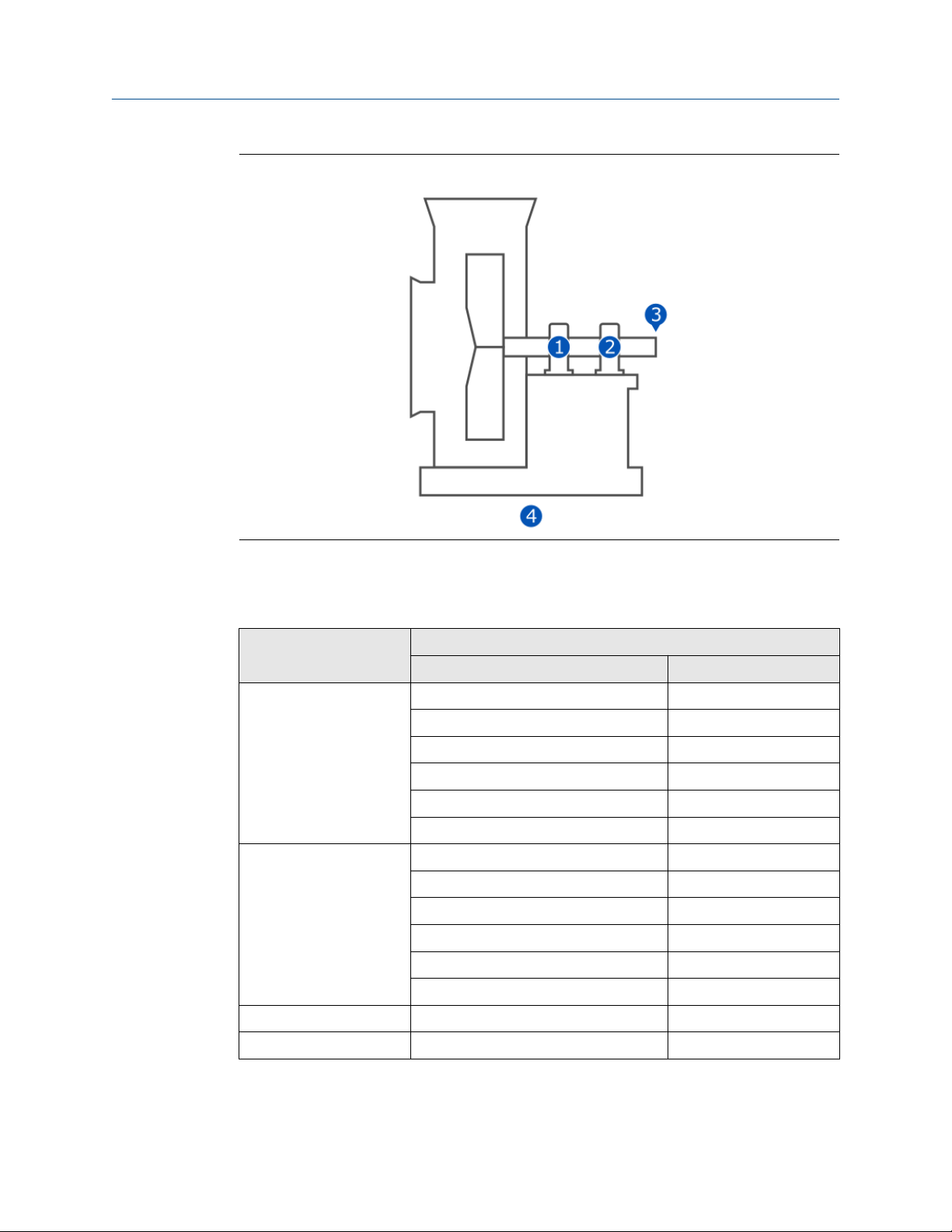
Configure the AMS Asset Monitor Operating Manual
June 2022 MHM-97924-PBF
Figure 6-31: Typical measuring points
One bearing vibration measurement with a piezoelectric accelerometer on each bearing
of the asset is the recommended measurement.
Table 6-13: Typical measuring points
Position Measuring point
Description Abbreviation
1 Outboard horizontal vibration FOH
Outboard vertical vibration FOV
Outboard axial vibration FOA
Outboard X vibration FOX
Outboard Y vibration FOY
Outboard temperature FOT
2 Inboard horizontal vibration FIH
Inboard vertical vibration FIV
Inboard axial vibration FIA
Inboard X vibration FIX
Inboard Y vibration FIY
Inboard temperature FIT
3 Speed FSPD
4 Auxiliary AUX
94 MHM-97924-PBF, Rev. 3.2

Operating Manual Configure the AMS Asset Monitor
MHM-97924-PBF June 2022
Available rules
Table 6-14 lists the selectable rules and their available input signals for the fan –
centrifugal, over hung asset.
Table 6-14: Fan – centrifugal, over hung
Rule Available input signals
CHARM Sensor Measuring
Alignment VI Piezo CHARM Accelerometer or
piezo electric
velocity sensor
Balance
VI Voltage
CHARM
2
VI Piezo CHARM Accelerometer or
Eddy current
measuring chain
piezo electric
velocity sensor
Bearing (using
VI Voltage
CHARM
VI Piezo CHARM Accelerometer FIH, FIV, FIA, FOH,
Eddy current
measuring chain
PeakVue Plus)
Blade pass VI Piezo CHARM Accelerometer or
piezo electric
velocity sensor
Looseness VI Piezo CHARM Accelerometer or
piezo electric
velocity sensor
Lubrication (using
VI Piezo CHARM Accelerometer FIH, FIV, FIA, FOH,
PeakVue Plus)
1
points
FIH, FIV, FIA, FOH,
FOV, or FOA
FIX, FIY, FOX, or
FOY
FIH, FIV, FIA, FOH,
FOV, or FOA
FIX, FIY, FOX, or
FOY
FOV, or FOA
FIH, FIV, FIA, FOH,
FOV, or FOA
FIH, FIV, FIA, FOH,
FOV, or FOA
FOV, or FOA
Configuration
Configured
bearings (see
Bearings, Shaft 1,
or Shaft 2)
Oil whirl VI Voltage
CHARM
Eddy current
measuring chain
FIX, FIY, FOX, or
FOY
Configured
bearing clearance
(see Bearings,
Shaft 1, or Shaft
2)
Flow turbulence –
2
fan
VI Piezo CHARM Accelerometer or
piezo electric
FIH, FIV, FIA, FOH,
FOV, or FOA
velocity sensor
All rules
VI Voltage
CHARM
3
VI Tach CHARM
(optionally 24 V
DI CHARM, 4 to
20 mA AI CHARM,
or External data
Eddy current
measuring chain
Passive magnetic
pickup, Hall-effect
sensor, or
Proximity probe
and converter
4
FIX, FIY, FOX, or
FOY
FSPD Accurate name
plate speed of the
asset is always
required
point)
1
A single measuring point is sufficient to activate the rule.
MHM-97924-PBF, Rev. 3.2 95

Configure the AMS Asset Monitor Operating Manual
June 2022 MHM-97924-PBF
2
One of the listed CHARMs is sufficient for the rule.
3
Actual rpm input is recommended.
4
Requires an external voltage supply.
At least one valid vibration sensor (connected and working properly) is needed to activate
a rule. The use of multiple sensors and vibration measuring points helps significantly to
detect asset condition deterioration and is recommended. The rules can work with
configured nominal asset speed (Running speed), but the monitoring of the actual rotor
speed with a VI Tach CHARM is recommended.
6.5.6 Gearbox – single reduction
Asset consisting of a single reduction gearbox with an input shaft and an output shaft.
Each shaft is supported by two bearings.
Typical measuring points
Figure 6-32: Typical measuring points
One bearing vibration measurement with a piezoelectric accelerometer on each bearing
of the asset is the recommended measurement.
Table 6-15: Typical measuring points
Position Measuring point
Description Abbreviation
1 Shaft 2 speed G2SPD
2 Shaft 2 outboard horizontal vibration G2OH
Shaft 2 outboard vertical vibration G2OV
Shaft 2 outboard axial vibration G2OA
Shaft 2 outboard X vibration G2OX
96 MHM-97924-PBF, Rev. 3.2

Operating Manual Configure the AMS Asset Monitor
MHM-97924-PBF June 2022
Table 6-15: Typical measuring points
Position Measuring point
Description Abbreviation
Shaft 2 outboard Y vibration G2OY
Shaft 2 outboard temperature G2OT
3 Shaft 2 inboard horizontal vibration G2IH
Shaft 2 inboard vertical vibration G2IV
Shaft 2 inboard axial vibration G2IA
Shaft 2 inboard X vibration G2IX
Shaft 2 inboard Y vibration G2IY
Shaft 2 inboard temperature G2IT
4 Shaft 1 outboard horizontal vibration G1OH
Shaft 1 outboard vertical vibration G1OV
Shaft 1 outboard axial vibration G1OA
Shaft 1 outboard X vibration G1OX
Shaft 1 outboard Y vibration G1OY
Shaft 1 outboard temperature G1OT
(continued)
5 Shaft 1 inboard horizontal vibration G1IH
Shaft 1 inboard vertical vibration G1IV
Shaft 1 inboard axial vibration G1IA
Shaft 1 inboard X vibration G1IX
Shaft 1 inboard Y vibration G1IY
Shaft 1 inboard temperature G1IT
6 Shaft 1 speed G1SPD
7 Oil quality GOQ
8 Auxiliary AUX
Available rules
Table 6-16 lists the selectable rules and their available input signals for the gearbox –
single reduction asset.
MHM-97924-PBF, Rev. 3.2 97

Configure the AMS Asset Monitor Operating Manual
June 2022 MHM-97924-PBF
Table 6-16: Gearbox – single reduction
Rule Available input signals
Alignment
Balance
2
2
Bearing (using
PeakVue Plus)
CHARM Sensor Measuring
VI Piezo CHARM Accelerometer or
piezo electric
velocity sensor
1
points
G1IH, G1IV, G1IA,
G1OH, G1OV,
G1OA, G2IH,
G2IV, G2IA,
G2OH, G2OV, or
G2OA
VI Voltage
CHARM
Eddy current
measuring chain
G1IX, G1IY,
G1OX, G1OY,
G2IX, G2IY,
G2OX, or G2OY
VI Piezo CHARM Accelerometer or
piezo electric
velocity sensor
G1IH, G1IV, G1IA,
G1OH, G1OV,
G1OA, G2IH,
G2IV, G2IA,
G2OH, G2OV, or
G2OA
VI Voltage
CHARM
Eddy current
measuring chain
G1IX, G1IY,
G1OX, G1OY,
G2IX, G2IY,
G2OX, or G2OY
VI Piezo CHARM Accelerometer G1IH, G1IV, G1IA,
G1OH, G1OV,
G1OA, G2IH,
G2IV, G2IA,
G2OH, G2OV, or
G2OA
Configuration
Configured
bearings (see
Bearings, Shaft 1,
or Shaft 2)
Tooth wear VI Piezo CHARM Accelerometer or
piezo electric
velocity sensor
G1IH, G1IV, G1IA,
G1OH, G1OV,
G1OA, G2IH,
G2IV, G2IA,
G2OH, G2OV, or
G2OA
Cracked or broken
tooth (using
PeakVue Plus,
under
development)
VI Piezo CHARM Accelerometer or
piezo electric
velocity sensor
G1IH, G1IV, G1IA,
G1OH, G1OV,
G1OA, G2IH,
G2IV, G2IA,
G2OH, G2OV, or
G2OA
Gear
misalignment
VI Piezo CHARM Accelerometer or
piezo electric
velocity sensor
G1IH, G1IV, G1IA,
G1OH, G1OV,
G1OA, G2IH,
G2IV, G2IA,
G2OH, G2OV, or
G2OA
98 MHM-97924-PBF, Rev. 3.2

Operating Manual Configure the AMS Asset Monitor
MHM-97924-PBF June 2022
Table 6-16: Gearbox – single reduction
Rule Available input signals
CHARM Sensor Measuring
Looseness VI Piezo CHARM Accelerometer or
Lubrication (using
PeakVue Plus)
Oil whirl VI Voltage
3
All rules
VI Piezo CHARM Accelerometer G1IH, G1IV, G1IA,
CHARM
VI Tach CHARM
(optionally 24 V
DI CHARM, 4 to
20 mA AI CHARM,
or External data
point)
(continued)
piezo electric
velocity sensor
Eddy current
measuring chain
Passive magnetic
pickup, Hall-effect
sensor, or
Proximity probe
and converter
1
points
G1IH, G1IV, G1IA,
G1OH, G1OV,
G1OA, G2IH,
G2IV, G2IA,
G2OH, G2OV, or
G2OA
G1OH, G1OV,
G1OA, G2IH,
G2IV, G2IA,
G2OH, G2OV, or
G2OA
G1IX, G1IY,
G1OX, G1OY,
G2IX, G2IY,
G2OX, or G2OY
FSPD Accurate name
4
Configuration
Configured
bearing clearance
(see Bearings,
Shaft 1, or Shaft
2)
plate speed of the
asset is always
required
6.5.7
1
A single measuring point is sufficient to activate the rule.
2
One of the listed CHARMs is sufficient for the rule.
3
Actual rpm input is recommended.
4
Requires an external voltage supply.
At least one valid vibration sensor (connected and working properly) is needed to activate
a rule. The use of multiple sensors and vibration measuring points helps significantly to
detect asset condition deterioration and is recommended. The rules can work with
configured nominal asset speed (Running speed), but the monitoring of the actual rotor
speed with a VI Tach CHARM is recommended.
Generic – rotating, center hung
Generic asset consisting of a device with a rotating part mounted in the center of two
bearings.
MHM-97924-PBF, Rev. 3.2 99

Configure the AMS Asset Monitor Operating Manual
June 2022 MHM-97924-PBF
Typical measuring points
Figure 6-33: Typical measuring points
One bearing vibration measurement with a piezoelectric accelerometer on each bearing
of the asset is the recommended measurement.
Table 6-17: Typical measuring points
Position Measuring point
Description Abbreviation
1 Outboard horizontal vibration GOH
Outboard vertical vibration GOV
Outboard axial vibration GOA
Outboard X vibration GOX
Outboard Y vibration GOY
Outboard temperature GOT
2 Inboard horizontal vibration GIH
Inboard vertical vibration GIV
Inboard axial vibration GIA
Inboard X vibration GIX
100 MHM-97924-PBF, Rev. 3.2
 Loading...