

Page 1

LH41A
Clamp On Ammeter
User Manual
• Mode d’emploi
• Bedienungshandbuch
• Manual d’Uso
• Manual de uso
• Användarhandbok
Page 2

Page 3

LH41A
Clamp On Ammeter
Users Manual
April 2007, Rev.2
©2007 Amprobe Test Tools.
All rights reserved. Printed in China
English
Page 4

1
Limited Warranty and Limitation of Liability
Your Amprobe product will be free from defects in material
and workmanship for 1 year from the date of purchase. This
warranty does not cover fuses, disposable batteries or damage
from accident, neglect, misuse, alteration, contamination, or
abnormal conditions of operation or handling. Resellers are not
authorized to extend any other warranty on Amprobe’s behalf.
To obtain service during the warranty period, return the product
with proof of purchase to an authorized Amprobe Test Tools
Service Center or to an Amprobe dealer or distributor. See Repair
Section for details. THIS WARRANTY IS YOUR ONLY REMEDY.
ALL OTHER WARRANTIES - WHETHER EXPRESS, IMPLIED OR
STAUTORY - INCLUDING IMPLIED WARRANTIES OF FITNESS FOR
A PARTICULAR PURPOSE OR MERCHANTABILITY, ARE HEREBY
DISCLAIMED. MANUFACTURER SHALL NOT BE LIABLE FOR ANY
SPECIAL, INDIRECT, INCIDENTAL OR CONSEQUENTIAL DAMAGES
OR LOSSES, ARISING FROM ANY CAUSE OR THEORY. Since some
states or countries do not allow the exclusion or limitation of an
implied warranty or of incidental or consequential damages, this
limitation of liability may not apply to you.
Repair
All test tools returned for warranty or non-warranty repair or for
calibration should be accompanied by the following: your name,
company’s name, address, telephone number, and proof of purchase.
Additionally, please include a brief description of the problem or the
service requested and include the test leads with the meter. Nonwarranty repair or replacement charges should be remitted in the
form of a check, a money order, credit card with expiration date, or a
purchase order made payable to Amprobe® Test Tools.
In-Warranty Repairs and Replacement – All Countries
Please read the warranty statement and check your battery
before requesting repair. During the warranty period any
defective test tool can be returned to your Amprobe® Test Tools
distributor for an exchange for the same or like product. Please
check the “Where to Buy” section on www.amprobe.com for a
list of distributors near you. Additionally, in the United States and
Canada In-Warranty repair and replacement units can also be sent
to a Amprobe® Test Tools Service Center (see address below).
Non-Warranty Repairs and Replacement – US and Canada
Non-warranty repairs in the United States and Canada should be
sent to a Amprobe® Test Tools Service Center. Call Amprobe®
Test Tools or inquire at your point of purchase for current repair
and replacement rates.
In USA In Canada
Amprobe Test Tools Amprobe Test Tools
Everett, WA 98203 Mississauga, ON L4Z 1X9
Tel: 877-AMPROBE (267-7623)
Tel: 905-890-7600
Non-Warranty Repairs and Replacement – Europe
European non-warranty units can be replaced by your Amprobe®
Test Tools distributor for a nominal charge. Please check the
“Where to Buy” section on www.amprobe.com for a list of
distributors near you.
European Correspondence Address*
Amprobe® Test Tools Europe
P.O. Box 1186
5602 BD Eindhoven
The Netherlands
*(Correspondence only – no repair or replacement available from
this address. European customers please contact your distributor.)
4
Page 5

International Electrical Symbols
Caution! Refer to this manual before using the meter
Meter is protected by Reinforced or Double Insulation
Complies with EU directives
Indicates this equipment should for disposal be
seperated as Waste Electrical and Electrical Equipment
according to the EU directive 2002/96/EG
Indicates item is a Type A Current sensor and that
application around removal from HAZARDOUS LIVE
conductors is permissible
CONTENTS Page
1 INTRODUCTION .............................................. 2
2 SPECIFICATIONS ...............................................
Electrical Data ..............................................3
2.1
2.2 General Data ................................................ 3
3 OPERATING INSTRUCTIONS ............................
3.1 Switch On .....................................................
3.2 Zero Adjustment ..........................................
3.3 Current Measurement .................................
3.4 Data Hold ......................................................
3.5 Auto Power Off .............................................
4 SAFETY .............................................................
5 BATTERY REPLACEMENT .................................
6 WARRANTY .....................................................
7 OTHER PRODUCTS ..........................................
3
4
4
4
4
4
4
5
6
6
7
1
Page 6
3
INTRODUCTION
HOLD
LH 41A
AUTO
40A
ZERO
OFF
ACDC
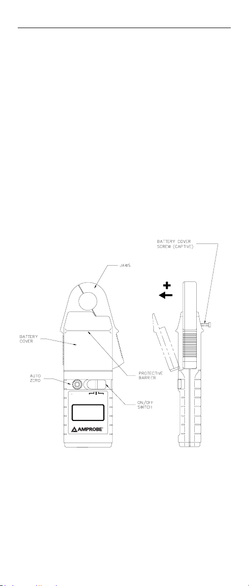
Fig. 1
The LH41A current clamp meter has been designed for
reliable and accurate non-intrusive measurement of DC
and AC currents using advanced Hall Effect technology.
Measurement features include:
• Non - intrusive AC and DC current measurement
• 1mA resolution
• Average responding, RMS calibrated
• Autoranging/ Autozeroing
• Data Hold
• Low battery indicator
• Auto Power Off
2
Page 7

SPECIFICATIONS
2.1 Electrical Data
(All accuracies stated at 23°C ± 1°C)
LH41A
Measuring Range .............. 0 - 40 A DC or AC pk
Autoranging ...................... 4A / 40A
Resolution .......................... 1 mA in 4 A range
10 mA in 40 A range
Accuracy
Basic Accuracy .................... ± 1.3% + 5 digits
Temperature coefficient ... ± 0.05% of rdg / °C
Frequency range ................ DC in DC
40 Hz to 400 Hz in AC
Overload capacity .............. 150 A
Dielectric strength ............. 3.7 kV RMS. 50 Hz 60s
(EN61010-2-032 Cat III, 300V Pollution Degree 2)
2.2 General Data
Operating temperature .... 0°C to + 50°C
Storage temperature with
Battery removed ................ - 20°C to + 60°C
Power supply ..................... 9 V, Alkaline battery
PP3, NEDA 1604 or
IEC6LR61
Battery life ......................... 15 hours dependent
duty cycle
Display ................................ 4000 count
Characters .......................... 10 mm high
Mechanical
LH41A
Dimensions ........................ 184 x 71 x 31 mm
(7.2 x 2.8 x 1.2 in.)
Max. jaw capacity .............. 19 mm ø cable
Max. jaw opening ............. 20 mm (.78 in.)
Weight ............................... 235 g (1.2 Lb)
3
Page 8

5
OPERATING INSTRUCTIONS
Refer to Fig. 1 for the main operating features of the
meter.
3.1 Switch On
Move the switch from the OFF / HOLD position to either
DC or AC to select the required mode of operation.
3.2 Zero Adjustment
When in DC mode the display zero may change due to
thermal shifts and other environmental conditions. An
auto zero adjustment is provided. Proceed as follows to
perform the adjustment:
• Ensure that the instrument is away from the current
carrying conductor and that the jaws are closed
during the adjustment cycle.
• Select the DC position of the power switch.
• Use the auto zero button to zero the display if
necessary.
The auto zero button can be used to null the effects of
the earth’s magnetic field on DC measurements.
3.3 Current Measurement
Select as required the DC or AC measurement option
using the power switch.
If necessary adjust the DC display to read zero as
described in section 3.2. Clamp the jaws of the instrument
around the conductor ensuring a good contact between
the closing faces of the jaws.
Observe and take measurements as required. Positive
output indicates that the current flow is in the direction
shown by the arrow on the instrument.
3.4 Data Hold
To activate the data hold, turn the power switch to the
OFF / HOLD position. The data will be held on the display
for approximately 10 seconds.
3.5 Auto Power Off
The meter will power down automatically after
approximately 8 minutes of inactivity.
4
Page 9

SAFETY
This product conforms to the latest directives concerning
safety and electromagnetic compatibility.
• European Low Voltage Directives 73/23/EEC and 93/68/
EEC
• European EMC Directives 89/336/EEC and 93/68/EEC
Safety Standards
BSEN61010-1: 2001. General Requirements.
Safety requirements for electrical equipment for
measurement, control and laboratory use.
BSEN61010-2-032: 2002. Particular requirements for hand
held current clamps for electrical measurement and test.
EMC Standards
RF Susceptibility
EN50082-1: 1992 3V/m Residential, Commercial and Light
Industry
RF Emissions
EN50081-1: 1992 Residential, Commercial
and Light Industry
FCC Part 15 Class B
This product is designed to be safe under the following
conditions:
− indoor use
− altitude up to 2000m
− temperature 0°C to +50°C
− maximum relative humidity 80% for
temperatures up to 31°C decreasing linearly to
40% relative humidity at 50°C.
Use of the meter on uninsulated conductors is limited to
300V RMS or DC and frequencies below 1kHz.
This meter complies with the requirements of the above
safety standard for 300V Cat III Pollution degree 2
Safety in its use is the responsibility of the operator who
must be a suitably qualified or authorised person.
Users of this equipment and or their employees are
reminded that Health and Safety Legislation require
them to carry out valid risk assessments of all electrical
work so as to identify potential sources of electrical
danger and risk of electrical injury such as from
inadvertent short circuits.
5
Page 10

7
Do not use the instrument if any part of it appears to
be damaged or if a malfunction of the instrument is
suspected.
When using the instrument ensure that your fingers are
behind the protective barrier see Fig. 1
Clean the case periodically by wiping it with a damp cloth
and detergent. Do not use abrasive cleaners or solvents.
Do not immerse the instrument in liquids.
BATTERY REPLACEMENT
SAFETY WARNING
Before removing the battery cover,
make sure that the instrument is
removed from any live electrical circuit.
When the Low Battery symbol is illuminated in the
display the minimum operating battery voltage has been
reached. Refer to Fig.1. and use the following procedure
to replace the battery.
Unclamp the meter from the conductor, turn it off using
the OFF / Hold power switch. Loosen the captive screw
which secures the battery cover. Lift the cover through
30° and pull it clear of the instrument body as shown in
Fig1. The battery is then accessible. Replace the battery
and re-fit the battery cover and fasten the screw.
Replacement with other than the specified type of
battery will invalidate the warranty. Fit only Type 9 V PP3,
Alkaline (MN1604 ).
6
Page 11

Page 12

LH41A
Clamp On Ammeter
Users Manual
Francias
Page 13

Page 14

Symboles électriques internationaux
Attention! Consulter le manuel de la pince avant
d’utiliser celle-ci
La pince est protégée par une double isolation
Conforme aux directives de l’UE
Ce symbole signifie que pour la mise au rebut de
l‘ appareil celui-ci doit etre trie en lant que dechet
d‘ appareil électrique et electronique selon la directive
de l‘ UE 2002/96/EC
Sur le produit signifie que celui-ci est un capteur de
courant de type A el que son installation ainsi que son
entevement autour d‘ un conducieur sous TENSION
DANGEREUS sont autorisés
TABLE DES MATIERES Page
1 INTRODUCTION ...................................... 2
2 CARACTERISTIQUES ............................... 3
Caractéristiques électriques ................. 3
2.1
2.2 Caractéristiques générales ................... 3
3 MODE D’EMPLOI ....................................
3.1 Mise en marche ....................................
3.2 Réglage du zéro ...................................
3.3 Mesure de courant ...............................
3.4 Bloquer la mesure ................................
3.5 Alimentation off automatique ...........
4
4
4
4
4
4
4 SECURITE ................................................ 5
5 REMPLACEMENT DE LA PILE ................. 6
6 GARANTIE ............................................... 6
7 AUTRES PRODUITS ................................. 7
1
Page 15
3
INTRODUCTION
HOLD
LH 41A
AUTO
40A
ZERO
OFF ACDC
La pince ampèremétrique LH41A, grâce à ses caractéristiques
technologiques de pointe basées sur l’effet Hall, ont été
conçues pour prendre des mesures fiables et précises, sans
ouverture de circuit, de courants AC et DC.
Les caractéristiques sont les suivantes :
• Mesure de courant AC et DC sans ouverture de circuit
• 1mA Résolution
• Etalonnage RMS référencé au sinus.
• Le changement de gammes et la remise à zéro
automatiques
• Blocage de la mesure
• Témoin de pile déchargée
• Alimentation off automatique
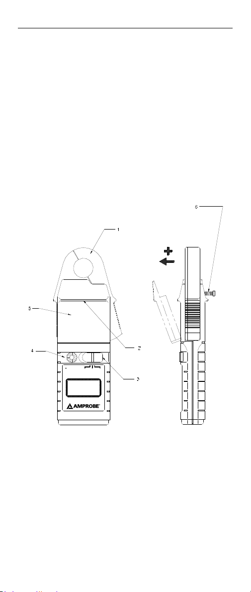
1. Machoires
2. Barriere Protectrice
3. Commutateur Marche/Arret
4. Zéro automatiques
5. Trappe a pile
6. Vise de trappe a pile (prisonniere)
2
Page 16

CARACTERISTIQUES
2.1 Caractéristiques électriques
(Toutes les précisions sont référencées à 23°C ± 1°C)
LH41A
Plage de mesure ................ 0- 40 A DC ou AC crête
Gammes automatiques ..... 4A / 40A
Résolution .......................... 1 mA (4 A)
10 mA (40 A)
Précision
Précision de base ............... ± 1.3% + 5 lecture
± 5 points
Coefficient de température ± 0,05% lecture / °C
Gamme de fréquence ....... DC
40 Hz à 400 Hz (AC)
Capacité de surcharge 150 A
Rigidité diélectrique .......... 3,7 kV v.eff. 50 Hz 60s
(EN61010-2-032 Cat III, 300V degré de pollution 2)
2.2 Caractéristiques générales
Température d’utilisation . 0°C à + 50°C
Température de stockage
sans pile ............................. - 20°C à + 60°C
Alimentation ..................... Pile 9 V alcaline
PP3, NEDA 1604 ou
IEC6LR61
Autonomie type de la pile 15 heures (Dépend du
cycle d’utilisation)
Affichage ........................... 4000 caractères
Caractères .......................... hauteur 10 mm
Caractéristiques mécaniques
LH41A
Dimensions ........................ 184 x 71 x 31 mm
(7.2 x 2.8 x 1.2 in.)
Capacité maxi. des
mâchoires ........................... câble 19 mm ø
Ouverture maxi. des
mâchoires ........................... 20 mm (.78 in.)
Poids ................................... 235 g (1.2 Lb)
3
Page 17

5
MODE D’EMPLOI
Pour les caractéristiques principales d’utilisation de la
pince, voir la Fig. 1.
3.1 Mise en marche
Faire passer le commutateur de la position OFF/ HOLD
(ARRET/MAINTIEN) sur DC ou AC pour sélectionner le
mode d’utilisation requis.
3.2 Réglage du zéro
En mode DC, les variations de température et autres
conditions d’ambiance peuvent modifier l’affichage du
zéro. Un ajustement automatique du zéro est inclus sur
la pince. Pour effectuer ce réglage, suivre la procédure
décrite :
• S’assurer que la pince est à l’écart du câble
conducteur et que les mâchoires sont fermées
pendant la procédure de réglage.
• Mettre le commutateur sur DC.
• Utiliser la touche auto zéro pour mettre l'affichager à
zéro si nécessaire.
Le bouton zéro automatique peut être utilisé pour
les effets du champs magnétique de la terre en cas de
mesure DC.
3.3 Mesure de courant
Sélectionner, selon le cas, l’option de mesure DC ou AC en
utilisant le commutateur.
Référer à la section 3.2 afin d’ajuster, si nécessaire, l’écran
DC pour lire le zéro. Placer la pince autour du conducteur
de courant en veillant à un bon contact des surfaces de
contact des mâchoires..
Effectuer et noter les mesures selon les besoins. Une
sortie positive indique que le courant passe dans le sens
indiqué par la flèche sur la pince.
3.4 Bloquer la mesure
Pour bloquer la mesure, mettre le commutateur marche/
arrêt sur OFF/ HOLD. L’affichage reste alors figé pendant
environ 10 secondes.
3.5 Alimentation off automatique
Le mesureur s’éteindra automatiquement après environ 8
minutes d’inactivité.
4
Page 18

SECURITE
La pince est conçue conformément aux directives sur les
basses tensions et la compatibilité électromagnétique les
plus récentes.
• Directives européennes sur les basses tensions
CEE/73/23 et CEE/93/68
• Directives européennes sur la compatibilité
électromagnétique CEE/89/336 et CEE/93/68
Normes de sécurité
BSEN61010-1: 2001. Exigences générales.
Exigences de sécurité pour les matériels électriques de
mesure, de contrôle et de laboratoire.
BSEN61010-2-032: 2005 Exigences particulières pour les
pinces ampéremétriques portables pour mesures et essais
électriques.
Normes de compatibilité électromagnétique
Susceptibilité radioélectrique
EN 50082-1: 1992 3V/m Usage domestique, commercial et
industriel léger 3V/m.
Emissions radioélectriques
EN 50081-1: 1992 Usage domestique, commercial et
industriel léger.
FCC Partie 15 Classe B
Cette pince est conçue pour être utilisée en toute sécurité
dans les conditions suivantes :
- utilisation en intérieur
- altitude maximum : 2000m
- température : 0°C à +50°C
- humidité relative maximum : 80% pour
des températures jusqu’à 31°C diminuant
linéairement jusqu’à 40% à 50°C.
L’utilisation de la pince sur des conducteurs non isolés
est limitée à 300V v.eff. ou d.c. et à des fréquences
inférieures à 1kHz. Cette pince est conforme aux normes
de sécurité ci-dessus pour le degré de pollution 2, 300V
Cat III.
Il incombe à l’opérateur d’utiliser la pince de manière
sûre. La pince ne peut être utilisée que par un personnel
qualifié et/ou autorisé.Si une partie quelconque de la
pince paraît être endommagée ou si on soupçonne un
défaut de fonctionnement, ne pas l’utiliser .
5
Page 19

7
Lorsqu’on utilise la pince, s’assurer que les doigts restent
en deçà de la barrière protectrice (voir Fig. 1).
Nettoyer périodiquement le boîtier en l’essuyant avec
un chiffon humide et un détergent. Ne pas utiliser de
produits abrasifs ou de solvants. Ne pas immerger la
pince dans des liquides.
REMPLACEMENT DE LA PILE
AVERTISSEMENT DE SECURITE
Avant de retirer le couvercle de
la trappe à pile, s’assurer que
l’appareil est éloigné de tout circuit
électrique sous tension.
Lorsque le symbole de pile déchargée s’allume à
l’affichage, la pile a atteint son niveau de tension de
fonctionnement minimum. Se reporter à la Fig.1. et suivre
la procédure suivante pour changer la pile.
Retirer la pince du conducteur, l’éteindre à l’aide du
commutateur OFF/HOLD. Desserrer la vis prisonnière de
fixation da la trappe à pile. Soulever la trappe à 30° et la
retirer de la pince comme illustré dans la Fig 1. La pile est
alors accessible. Remplacer la pile, reposer la trappe et
serrer la vis.
La pose d’une pile autre que la pile spécifiée invalide la
garantie. Ne poser qu’une pile alcaline 9 V de type PP3
(MN1604 ).
Limitation de garantie et de responsabilité
Amprobe garantit l’absence de vices de matériaux et de
fabrication de ce produit dans des conditions normales
d’utilisation et d’entretien pendant une période d’un an prenant
effet à la date d’achat. Cette garantie ne s’applique pas aux
fusibles, aux piles jetables ni à tout produit mal utilisé, modifié,
contaminé, négligé ou endommagé par accident ou soumis
à des conditions anormales d’utilisation et de manipulation.
Les distributeurs agréés par Amprobe ne sont pas autorisés à
appliquer une garantie plus étendue au nom de Amprobe. Pour
bénéficier de la garantie, renvoyez le produit accompagné d’un
justificatif d’achat auprès d’un centre de services agréé par
Amprobe Test ou du distributeur ou du revendeur Amprobe.
Voir la section Réparation ci-dessus pour tous les détails. LA
PRESENTE GARANTIE EST LE SEUL ET EXCLUSIF RECOURS TOUTES
AUTRES GARANTIES, EXPLICITES, IMPLICITES OU STATUTAIRES,
NOTAMMENT LE CAS ECHEANT LES GARANTIES DE QUALITE
MARCHANDE OU D’ADAPTATION A UN OBJECTIF PARTICULIER
SONT EXCLUES PAR LES PRESENTES. LE FABRICANT NE SERA EN
AUCUN CAS TENU RESPONSABLE DE DOMMAGES PARTICULIERS,
INDIRECTS, ACCIDENTELS OU CONSECUTIFS, NI D’AUCUNS DEGATS
OU PERTES DE DONNEES, SUR UNE BASE CONTRACTUELLE,
6
Page 20

EXTRA-CONTRACTUELLE OU AUTRE. Etant donné que certains
pays ou états n’admettent pas les limitations d’une condition
de garantie implicite, ou l’exclusion ou la limitation de dégâts
accidentels ou consécutifs, les limitations et les exclusions de cette
garantie ne s’appliquent pas obligatoirement à chaque acheteur.
Réparation
Tous les appareils qui sont envoyés pour réparation ou calibrage
dans le cadre de la garantie ou en dehors de la garantie doivent
être accompagnés de ce qui suit: Nom du client, nom de la firme,
adresse, numéro de téléphone et preuve d’achat. Prière de
joindre en outre à l’appareil de mesure une brève description du
problème ou de la maintenance désirée ainsi que les lignes de
mesure. Les frais pour les réparations en dehors de la garantie
ou pour le remplacement d’instruments doivent être payés par
chèque, virement bancaire, carte de crédit (numéro de carte
de crédit avec date d’expiration) ou une commande doit être
formulée au bénéfice de Amprobe Test Tools.
Réparations ou remplacement sous garantie – tous les pays.
Veuillez lire la déclaration de garantie subséquente et contrôler
la pile avant de demander des réparations. Pendant la période
de garantie, tous les appareils défectueux peuvent être renvoyés
à un distributeur Amprobe Test Tools pour remplacement par
un appareil identique ou un produit similaire. Un répertoire des
distributeurs agréés se trouve dans la section « Where to Buy »
(points de vente) sur le site web www.amprobe.com. De plus, aux
USA et au Canada, les appareils peuvent être envoyés à un centre
de service après-vente Amprobe Test Tools (adresse voir plus loin)
pour réparation ou remplacement.
Réparations ou remplacement en dehors de la garantie - USA et
Canada
Pour les réparations en dehors de la garantie aux Etats-Unis et
au Canada, les appareils sont envoyés à un centre de service
après-vente Amprobe Test Tools. Vous pouvez obtenir des
renseignements sur les prix de réparation et de remplacement
actuellement en vigueur auprès de Amprobe Test Tools ou du
point de vente.
Aux USA : Au Canada :
Amprobe Test Tools Amprobe Test Tools
Everett, WA 98203 Mississauga, ON L4Z 1X9
Tél.: 877-AMPROBE (267-7623) Tél.: 905-890-7600
Réparations ou remplacement en dehors de la garantie - Europe
Les appareils hors garantie peuvent être remplacés contre
paiement par le distributeur Amprobe Test Tools compétent. Un
répertoire des distributeurs agréés se trouve dans la section «
Where to Buy » (points de vente) sur le site web www.amprobe.
com.
Adresse de correspondance pour l’Europe*
Amprobe Test Tools Europe
P. O. Box 1186
5602 BD Eindhoven
Pays-Bas
*(Uniquement correspondance – pas de réparations, pas de
remplacement à cette adresse. Les clients en Europe s’adressent
au distributeur compétent.)
7
Page 21

Page 22

LH41A
Clamp On Ammeter
Users Manual
Deutsch
Page 23

Page 24

Internationale Elektrosymbole
Achtung! Vor Benützung des Meßgerätes des lesen sie
dieses Handbuch zu Rate ziehen
Meßgerät Ist durch verstarkte oder doppelte isolierung
geschützt
Übereinstimmung mit EU-Richtlinien
Diesses Symbol zeigt an, dass dieses Gerat gesondert ais
Elektroschrott oder Elektronikaltgerat entsorgt werden
muss gemass EU Richtlinie 2002/96/EC
lst dieses symbol auf dem Produkt abgebildel, so ist
dies ein Stromfuhler Typ A Der Einsatz in Anwendungen
mit und/oder dem Enfernen von GEFAHRLICHEN
STROMFUHRENDEN Stromleitrn ist zuiassig
INHALT Seite
1 EINFÜHRUNG ................................................ 2
2 TECHNISCHE DATEN .....................................
Elektrische Daten ........................................3
2.1
2.2 Allgemeine Daten .......................................3
3 BEDIENUNGSANLEITUNG ............................
3.1 Einschalten ..................................................
3.2 Nullabgleich ................................................
3.3 Strommessung .............................................
3.4 Meßwerthaltefunktion ..............................
3.5 Automatische Abschaltung .......................
4 SICHERHEIT ...................................................
5 BATTERIEWECHSEL .......................................
6 GARANTIE .....................................................
7 WEITERES PRODUKTANGEBOT ....................
3
4
4
4
4
4
4
5
6
6
7
1
Page 25

3
EINFÜHRUNG
HOLD
LH 41A
AUTO
40A
ZERO
OFF ACDC
Das LH41A Zangen-Strommesser gewährleistet
zuverlässige und genaue Messungen von Gleich- und
Wechselstrom auf Grundlage der modernen Hall-EffektMethode. Zu den Meßfunktionen gehören:
• Wechselstrom/Gleichstrom (ohne Unterbrechung des
Stromkreises)
• Auflösung 1mA
• Durchschnittsanzeige, Effektivwerteichung
• Automatische Bereichseinstellung und automatische
Nullung
• Meßwert-Haltefunktion
• Batterieentladungsanzeiger
• Automatische Abschaltung
1. Klemmzangen
2. Schutzsperre
3. Ein-L Ausschalter
4. automatischer Nullabgleich
5. Batteriedeckel
6. Batteriedeckel Feststellschraube
2
Page 26

TECHNISCHE DATEN
Elektrische Daten
(Alle angegebenen Genauigkeiten sind auf 23°C ± 1°C
bezogen.)
LH41A
Meßbereich ........................ 0 - 40 A DC oder AC max
Autom. Bereichswahl ........ 4A / 40A
Auflösung .......................... 1 mA im 4 A Bereich
10 mA im 40 A Bereich
Genauigkeit
Grundgenauigkeit ............. ± 1.3% + 5 des Meßwertes
± 5 Stellen
Temperaturkoeffizient ...... ± 0,05% des Meßwertes / °C
Frequenzbereich ................ DC bei DC
40Hz bis 400 Hz bei AC
Überlastungsfähigkeit 150 A
Dielektrische Festigkeit ..... 3,7kV Eff 50 Hz 60s
(EN61010-2-032 Kat III, 300V Verschmutzungsgrad 2)
2.2 Allgemeine Daten
Betriebstemperatur ........... 0°C bis +50°C
Lagertemperatur bei
entfernter Batterie ............ - 20°C bis + 60°C
Leistungsversorgung ......... 9 V, Alkali-Batterie
PP3, NEDA 1604 oder
IEC6LR61
Batterielebensdauer .......... 15 Stunden (abhängig vom
Betriebszyklus)
Anzeige .............................. 4000-Digit
Ziffern ................................ 10 mm
Mechanische Daten
LH41A
Abmessungen .................... 184 x 71 x 31 mm
(7.2 x 2.8 x 1.2 in.)
Max. Kabeldurchmesser .... 19 mm
Max. Zangenöffnung ........ 20 mm (.78 in.)
Gewicht .............................. 235 g (1.2 Lb)
3
Page 27

5
BEDIENUNGSANLEITUNG
Die wesentlichen Betriebseigenschaften sind in Abb. 1
dargestellt.
3.1 Einschalten
Den Schalter von der OFF / HOLD-Position je nach
gewünschter Betriebsart auf DC oder AC stellen.
3.2 Nullabgleich
Im Gleichstrombetrieb kann sich die Nullanzeige
aufgrund von Wärmeschwankungen und anderen
Umweltbedingungen ändern.
Ein automatischer Nullpunktabgleich ist vorhanden.
Dabei ist wie folgt zu verfahren:
• Es ist sicherzustellen, daß das Meßgerät nicht mit
dem stromführenden Leiter in Berührung steht und
daß die Zangenbacken während des Nullabgleichs
geschlossen sind.
• Den Schiebeschalter auf DC-Position stellen.
• Zur Anzeige von Bezugswerten oder zum
Nullabgleich die ZERO-Taste betätigen.
Mit der Taste für automatischen Nullpunktabgleich kann
der Einfluss des Erdmagnetfeldes auf DC-Messungen
kompensiert werden
3.3 Strommessung
Den Schiebeschalter je nach gewünschter Betriebsart auf
DC oder AC stellen.
Bei Bedarf gleichen Sie den DC-Nullpunkt wie in Abschnitt
3.2 beschrieben ab. Die Zangenbacken des Meßkopfes an
den Leiter anlegen und dabei einen guten Kontakt zwischen
den Schließflächen der Zangenbacken sicherstellen.
Anschließend unter sorgfältiger Beobachtung des
Meßgerätes die gewünschten Messungen durchführen.
Eine positive Anzeige weist darauf hin, daß der Stromfluß
in die vom Meßkopfpfeil angegebene Richtung verläuft.
3.4 Meßwerthaltefunktion
Zur Aktivierung der Meßwerthaltefunktion den
Schiebeschalter auf die OFF / HOLD-Position stellen.
Der Meßwert wird daraufhin ca. 10 Sekunden auf dem
Bildschirm festgehalten.
3.5 Automatische Abschaltung
Werden ca. 8 Minuten lang keine Messungen
durchgeführt, schaltet sich das Messgerät automatisch ab.
4
Page 28

SICHERHEIT
Das Produkt entspricht den aktuellen Richtlinien
hinsichtlich Sicherheit und elektromagnetischer
Verträglichkeit.
• Europäische Niederspannungsrichtlinien 73/23/EWG
und 93/68/EWG
• Europäische EMV-Richtlinien 89/336/EWG und 93/68/
EWG
Sicherheitsnormen
BSEN61010-1: 2001 Allgemeine Vorschriften,
Sicherheitsvorschriften für Elektroausrüstung für Meß-,
Regel- und Laborzwecke
BSEN61010-2-032: 2002 Sondervorschriften für
handgeführte Sondengeräte für elektrische Messungen
und Prüfungen
EMV-Normen
HF-Empfindlichkeit
EN 50082-1: 1992 3V/m Wohnräume, Gewerbe und
Leichtindustrie
HF-Emissionen
EN 50081-1: 1992 Wohnräume, Gewerbe und
Leichtindustrie
FCC Teil 15 Klasse B
Der sichere Betrieb des Meßgerätes ist unter folgenden
Bedingungen gewährleistet::
- keine Verwendung im Freien
- max. Einsatzhöhe: 2000m
- Temperatur: 0°C bis +50°C
- Maximale relative Luftfeuchtigkeit: 80%
für Temperaturen bis zu 31°C (87°F), linear
abnehmend bis 50% relative Luftfeuchtigkeit
bei 40°C (104°F)
Der Einsatz des Meßgerätes bei nicht isolierten Leitern
ist auf 300V Eff oder d.c. und Frequenzen unter 1kHz
begrenzt. Das Meßgerät entspricht den Anforderungen
der obengenannten Sicherheitsnorm für 300V Kat III
Verschmutzungsgrad 2.
Für die sichere Bedienung des Meßgerätes ist der Benutzer
verantwortlich, der über die entsprechende Qualifikation
und die notwendige Befugnis verfügen muß.
Ein (vermutlich) beschädigtes bzw. nicht funktionierendes
5
Page 29

7
Gerät darf nicht benutzt werden.
Bei der Verwendung des Meßgerätes ist darauf zu
achten, daß die Finger hinter der Schutzisolierung (siehe
Abb. 1) sind.
Das Gerät regelmäßig mit Hilfe eines feuchten Tuches
und eines Reinigungsmittels säubern. Keine ätzenden
Reinigungsmittel bzw. Lösungsmittel verwenden. Den
Meßkopf nicht in Flüssigkeiten tauchen.
BATTERIEWECHSEL
SICHERHEITSHINWEIS
Vor dem Entfernen des Batteriefachdeckels ist
sicherzustellen, daß alle externen Spannungen
vom Instrument getrennt wurden.
Wenn der Batterieentladungsanzeiger aufleuchtet, ist die
Mindestbatteriebetriebsspannung erreicht (siehe Abb. 1).
Der Batteriewechsel ist wie folgt durchzuführen:
Das Meßgerät vom Leiter trennen und mit Hilfe des
OFF / Hold-Schalters ausschalten. Die Sicherungsschraube
des Batteriefachdeckels lösen. Den Deckel um 30°
anheben und, wie in Abb. 1 dargestellt, vom Meßkopf
wegziehen. Die Batterie kann jetzt ausgewechselt
werden. Anschließend den Batteriefachdeckel wieder
schließen und mit der Schraube sichern.
Die Verwendung einer nicht vorschriftsmäßigen
Ersatzbatterie macht die Garantie nichtig.
Nur Batterietyp 9V PP3, Alkali (MN1604)
Beschränkte Gewährleistung und Haftungsbeschränkung
Es wird gewährleistet, dass dieses Amprobe-Produkt für die
Dauer von einem Jahr ab dem Kaufdatum frei von Material- und
Fertigungsdefekten ist. Diese Gewährleistung erstreckt sich
nicht auf Sicherungen, Einwegbatterien oder Schäden durch
Unfälle, Nachlässigkeit, Missbrauch, Änderungen oder abnormale
Betriebsbedingungen bzw. unsachgemäße Handhabung. Die
Verkaufsstellen sind nicht dazu berechtigt, diese Gewährleistung
im Namen von Amprobe zu erweitern. Um während der
Gewährleistungsperiode Serviceleistungen zu beanspruchen,
das Produkt mit Kaufnachweis an ein autorisiertes Amprobe
Test Tools Service-Center oder an einen Amprobe-Fachhändler/Distributor einsenden. Einzelheiten siehe Abschnitt „Reparatur“
oben. DIESE GEWÄHRLEISTUNG STELLT DEN EINZIGEN UND
ALLEINIGEN RECHTSANSPRUCH AUF SCHADENERSATZ DAR. ALLE
ANDEREN GEWÄHRLEISTUNGEN - VERTRAGLICH GEREGELTE
ODER GESETZLICHE VORGESCHRIEBENE - EINSCHLIESSLICH
DER GESETZLICHEN GEWÄHRLEISTUNG DER MARKTFÄHIGKEIT
UND DER EIGNUNG FÜR EINEN BESTIMMTEN ZWECK, WERDEN
ABGELEHNT DER HERSTELLER ÜBERNIMMT KEINE HAFTUNG
FÜR SPEZIELLE, INDIREKTE, NEBEN- ODER FOLGESCHÄDEN ODER
VERLUSTE, DIE AUF BELIEBIGER URSACHE ODER RECHTSTHEORIE
6
Page 30

BERUHEN. Weil einige Staaten oder Länder den Ausschluss
oder die Einschränkung einer implizierten Gewährleistung
sowie von Begleit- oder Folgeschäden nicht zulassen, ist diese
Gewährleistungsbeschränkung möglicherweise für Sie nicht
gültig.
Reparatur
Zu allen Geräten, die zur Reparatur oder Kalibrierung im
Rahmen der Garantie oder außerhalb der Garantie eingesendet
werden, muss folgendes beigelegt werden: Name des Kunden,
Firmenname, Adresse, Telefonnummer und Kaufbeleg.
Zusätzlich bitte eine kurze Beschreibung des Problems oder
der gewünschten Wartung sowie die Messleitungen dem
Messgerät beilegen. Die Gebühren für Reparaturen außerhalb
der Garantie oder für den Ersatz von Instrumenten müssen als
Scheck, Geldanweisung, Kreditkarte (Kreditkartennummer mit
Ablaufdatum) beglichen werden oder es muss ein Auftrag an
Amprobe Test Tools formuliert werden.
Garantiereparaturen oder -austausch - alle Länder
Bitte die nachfolgende Garantieerklärung lesen und die Batterie
prüfen, bevor Reparaturen angefordert werden. Während der
Garantieperiode können alle defekten Geräte zum Umtausch
gegen dasselbe oder ein ähnliches Produkt an den Amprobe
Test Tools-Distributor gesendet werden. Ein Verzeichnis der
zuständigen Distributoren ist im Abschnitt „Where to Buy“
(Verkaufsstellen) auf der Website www.amprobe.com zu finden.
Darüber hinaus können in den USA und in Kanada
Geräte an ein Amprobe Test Tools Service-Center (Adresse siehe
weiter unten) zur Reparatur oder zum Umtausch eingesendet
werden.
Reparatur oder Austausch - ausserhalb der Garantieperiode - USA
und Kanada
Für Reparaturen außerhalb der Garantie in den Vereinigten
Staaten und in Kanada werden die Geräte an ein Amprobe
Test Tools Service-Center gesendet. Auskunft über die derzeit
geltenden Reparatur- und Austauschgebühren erhalten Sie von
Amprobe Test Tools oder der Verkaufsstelle.
In den USA: In Kanada:
Amprobe Test Tools Amprobe Test Tools
Everett, WA 98203 Mississauga, ON L4Z 1X9
Tel: 877-AMPROBE (267-7623) Tel: 905-890-7600
Reparaturen und Austausch außerhalb der Garantie - Europa
Geräte außerhalb der Garantie können durch den zuständigen
Amprobe Test Tools-Distributor gegen eine Gebühr ersetzt
werden. Ein Verzeichnis der zuständigen Distributoren ist im
Abschnitt „Where to Buy“ (Verkaufsstellen) auf der Website
www.amprobe.com zu finden.
Korrespondenzanschrift für Europa*
Amprobe Test Tools Europe
P. O. Box 1186
5602 BD Eindhoven
Niederlande
*(Nur Korrespondenz – keine Reparaturen, kein Umtausch
unter dieser Anschrift. Kunden in Europa wenden sich an den
zuständigen Distributor.)
7
Page 31

Page 32

LH41A
Clamp On Ammeter
Users Manual
Italiano
Page 33

Page 34

Convenzioni tipografiche internazionali
Attenzione! Consultare il manuale prime dell’uso
Lo strumento è protetto da isolamento doppio o
riforzato.
Conforme alle direttive UE
Questo simbolo indica che questa apparecchialura deve
essere raccolta e trattata separatamrnte in accordo con
la Direttiva Europea 2002/96/EC sui Rifiuti di Apparecchi
Elettrici ed Elettronici
Sul prodotto indica che e un sensore di Corrente Tipo A
e che puo essere apphcata attorno a condutton SOTTO
TENSIONE o nmossa da essi
INDICE Pagina
1 PRESENTAZIONE ...........................................2
2 CARATTERISTICHE TECNICHE .......................
Caratteristiche elettriche ...........................3
2.1
2.2 Caratteristiche generali .............................3
3 ISTRUZIONI PER IL FUNZIONAMENTO ........
3.1 Accensione ..................................................
3.2 Regolazione a zero ....................................
3.3 Misura della corrente .................................
3.4 Mantenimento dei dati .............................
3.5 Spegnimento automatico ..........................
4 SICUREZZA ....................................................
5 SOSTITUZIONE
DELLA BATTERIA ..........................................
6 GARANZIA ....................................................
7 ALTRI PRODOTTI ...........................................
3
4
4
4
4
4
4
5
6
6
7
1
Page 35

3
PRESENTAZIONE
HOLD
LH 41A
AUTO
40A
ZERO
OFF ACDC
L’innovativo amperometro a tenaglia LH41A è stato
progettato appositamente per ottenere affidabilità e
precisione nelle misure non intrusive delle correnti a CA
e CC utilizzando la più avanzata tecnologia dell’effetto
di Hall.
Le caratteristiche di misura sono:
• Misura di corrente a CA e CC non intrusiva
• 1mA Risoluzione
• Risposta media, RMS calibrata
• Ricerca scala e azzeramento automatici
• Mantenimento dei dati
• Indicatore batteria scarica
• Spegnimento automatico
Fig. 1
1. Ganasce a tenaglia
2. Barriera Protettiva
3. Interruttore Acceso/Spento
4. Regolazione Zero
5. Coperchio Batterie
6. Vite coperchio batterie (prigioniera)
2
Page 36

CARATTERISTICHE TECNICHE
2.1 Caratteristiche elettriche
(Tutte le precisioni dichiarate a 23°C ± 1°C)
LH41A
Gamma di misura .............. 0 - 40 A CC o CA pk
Autogamma ....................... 4A / 40A
Risoluzione ........................ 1 mA nella gamma 4 A
10 mA nella gamma 40A
Precisione
Precisione di base .............. ±± 1.3% + 5 cifre
Coefficiente di temperatura ± 0,05% di lett. / °C
Spettro di frequenza ......... CC in CC
40 Hz a 400 Hz in CA
Sovraccarico massimo 150 A
Resistenza dielettrica ........ 3.7kV r.m.s. 50 Hz 60s
(EN61010-2-032 Cat III, 300V Grado di
contaminazione 2)
2.2 Caratteristiche generali
Temperatura di
funzionamento .................. 0°C a +50°C
Temperatura di immagazzinaggio
con batteria rimossa .......... - 20°C a + 60°C
Alimentazione ................... 9 V, batteria alcalina
PP3, NEDA 1604 o
IEC6LR61
Durata batteria .................. 15 ore (a seconda del
ciclo di lavoro)
Display ............................... 4000 punti
Caratteristiche ................... Altezza10 mm
Meccaniche
LH41A
Dimensioni ......................... 184 x 71 x 31 mm
(7.2 x 2.8 x 1.2 in.)
Massima capacità
ganasce .............................. 19 mm ø cavo
Massima apertura ganasce 20 mm (.78 in.)
Peso .................................... 235 g (1.2 Lb)
3
Page 37

5
ISTRUZIONI PER IL FUNZIONAMENTO
Consultare la Fig. 1 per le principali caratteristiche di
funzionamento dell’amperometro.
3.1 Accensione
Spostare il commutatore dalla posizione OFF / HOLD
(SPEGNIMENTO/MANTENIMENTO) su CC o CA per
selezionare il modo di funzionamento richiesto.
3.2 Regolazione a zero
Quando ci si trova nel modo a CC, la visualizzazione dello
zero potrebbe cambiare a causa di variazioni termiche e
di altre condizioni ambientali.
È inclusa una regolazione di auto zero.
Procedere come segue per effettuare la regolazione:
• Assicurarsi che lo strumento sia lontano dall’attuale
conduttore di corrente e che le ganasce siano chiuse
durante il ciclo di regolazione.
• Selezionare la posizione a CC del commutatore di
accensione.
• Usare il tasto zero per azzerare il display, se
necessario.
Il pulsante di auto zero può essere usato per annullare gli
effetti del campo magnetico terrestre sulle misurazioni
in C.C.
3.3 Misura della corrente
Selezionare come richiesto l’opzione di misurazione a CA
e CC usando il commutatore di accensione.
Se necessario regolare il display C.C. in modo da azzerarlo
seguendo le istruzioni contenute nella sezione 3.2.
Bloccare le ganasce della sonda attorno al conduttore
assicurandosi che vi sia un buon contatto tra le superfici
di chiusura delle ganasce.
Rilevare ed annotare le misure come richiesto. L’uscita
positiva indica che il flusso di corrente è nella direzione
indicata dalla freccia sulla sonda.
3.4 Mantenimento dei dati
Per attivare il mantenimento dei dati, portare il
commutatore di accensione nella posizione OFF / HOLD
(SPEGNIMENTO/MANTENIMENTO). I dati verranno
visualizzati sul display per circa 10 secondi.
3.5 Spegnimento automatico
Lo strumento si spegnerà automaticamente dopo circa 8
minuti di inattività.
4
Page 38

SICUREZZA
Questo prodotto è conforme alle ultime direttive in materia di
sicurezza e compatibilità elettromagnetica.
• Direttive europee sulle basse tensioni 73/23/EEC e 93/68/EEC
• Direttive europee EMC 89/336/EEC e 93/68/EEC
Standard di sicurezza
BSEN61010-1: 2001. Requisiti generali.
I requisiti di sicurezza per le apparecchiature elettriche di misura,
controllo e per laboratorio.
BSEN61010-2-032: 2002 Requisiti speciali per dispositivi a
tenaglia portatili per misure e prove elettriche.
Standard EMC
suscettibilità RF
EN50082-1: 1992 3V/m domestica, commerciale e per l’industria
dell’illuminazione
Emissioni RF
EN50081-1: 1992 domestica, commerciale e per l’industria
dell’illuminazione
FCC Parte 15 Classe B
Questo prodotto è stato progettato per offrire un
funzionamento sicuro nelle seguenti condizioni:
- uso in interni
- altitudine fino ad un massimo di 2000m
- temperatura da 0°C a +50°C
- massima umidità relativa 80% per temperature
sino a 31°C, con diminuzione lineare sino al 40% di
umidità relativa a
50°C.
L’uso dell'amperometro su conduttori non isolati è limitato a
300V r.m.s. o c.c. ed a frequenze inferiori a 1kHz. Il presente
amperometro è conforme ai requisiti degli standard di sicurezza
di cui sopra per 300V Cat. III grado di contaminazione 2.
Il suo uso sicuro è responsabilità dell’operatore che deve essere
una persona autorizzata ed adeguatamente qualificata.
Non usare lo strumento se un qualsiasi componente appare
danneggiato o se si sospetta un malfunzionamento dello
strumento.
Nell’usare lo strumento assicurarsi che le dita non siano dietro
alla barriera protettiva consultare la Fig. 1
Pulire l’involucro periodicamente con un panno umido e del
detergente. Non usare detergenti o solventi abrasivi. Non
immergere la sonda nei liquidi.
5
Page 39

7
SOSTITUZIONE DELLA BATTERIA
AVVISO DI SICUREZZA
Prima di togliere il coperchio della batteria,
verificare che lo strumento sia lontano da
qualsiasi circuito elettrico in tensione.
Quando il simbolo di batterie scariche è acceso sul
display, è stata raggiunta la tensione di funzionamento
minima della batteria. Consultare la Fig. 1 ed adottare la
seguente procedure per sostituire le batterie.
Sganciare l’amperometro dal conduttore, spegnerlo
usando il commutatore OFF / Hold power (SPEGNIMENTO/
Mantenimento alimentazione).
Svitare la vite di fissaggio del coperchio delle batterie.
Sollevare il coperchio di 30° e staccarlo dal corpo della
sonda come mostrato nella Fig. 1. Adesso è quindi
possibile accedere alle batterie. Sostituire le batterie,
reinstallare il coperchio ed avvitare la vite.
Se le batterie vengono sostituite da altre diverse dal
tipo specificato, ciò invaliderà la garanzia. Montare solo
batterie tipo 9 V PP3, alcaline (MN1604 ).
Garanzia limitata e restrizioni di responsabilità
Questo prodotto Amprobe sarà esente da difetti di materiale e
fabbricazione per 1 anno a decorrere dalla data di acquisto. Sono
esclusi da questa garanzia i fusibili, le pile monouso e i danni
causati da incidenti, negligenza, uso improprio, alterazione,
contaminazione o condizioni anomale di funzionamento o
manipolazione. I rivenditori non sono autorizzati a offrire
alcun’altra garanzia a nome della Amprobe. Per richiedere un
intervento durante il periodo di garanzia, restituire il prodotto,
allegando la ricevuta di acquisto, a un centro di assistenza
autorizzato Amprobe Test Tools oppure a un rivenditore o
distributore Amprobe locale. Per ulteriori informazioni vedere
la sezione Riparazioni. QUESTA GARANZIA È IL SOLO RICORSO
A DISPOSIZIONE DELL’ACQUIRENTE, E SOSTITUISCE QUALSIASI
ALTRA GARANZIA, ESPRESSA, IMPLICITA O PREVISTA DALLA
LEGGE, COMPRESA, MA NON A TITOLO ESCLUSIVO, QUALSIASI
GARANZIA IMPLICITA DI COMMERCIABILITÀ O DI IDONEITÀ PER
SCOPI PARTICOLARI. IL PRODUTTORE NON SARÀ RESPONSABILE
DI DANNI O PERDITE SPECIALI, INDIRETTI O ACCIDENTALI,
DERIVANTI DA QUALSIASI CAUSA O TEORIA. Poiché alcuni
stati o Paesi non permettono l’esclusione o la limitazione
di una garanzia implicita o di danni accidentali o indiretti,
questa limitazione di responsabilità potrebbe non applicarsi
all’acquirente.
Riparazione
Per tutti gli apparecchi che vengono spediti per la riparazione
o la calibrazione durante la validità della garanzia o al di fuori
della garanzia, è necessario allegare quanto segue: nome
del cliente, nome dell’impresa, indirizzo, numero di telefono
e ricevuta d’acquisto. Si prega inoltre di allegare una breve
6
Page 40

descrizione del problema verificatosi o della manutenzione
richiesta come pure i conduttori di misura insieme al misuratore.
Gli importi per le riparazioni effettuate al di fuori della garanzia
o per la sostituzione di strumenti sono pagabili tramite assegno
bancario, versamento bancario, carta di credito (numero della
carta di credito con data di scadenza), altrimenti sarà necessario
formulare un ordine alla Amprobe Test Tools.
Riparazioni in garanzia o sostituzione in garanzia - tutti i paesi
Si prega di leggere attentamente la seguente dichiarazione di
garanzia e di verificare le batterie, prima di richiedere eventuali
riparazioni. Durante il periodo di garanzia tutti gli apparecchi
difettosi potranno essere spediti al distributore della Amprobe
Test Tools per una sostituzione con gli stessi modelli o un modello
simile. Un elenco dei distributori competenti è da apprendere
al paragrafo “Where to Buy” (centri di vendita) sul sito Internet
www.amprobe.com. Inoltre, gli apparecchi possono essere
spediti negli USA e in Canada ad un Amprobe Test Tools ServiceCenter (per l’indirizzo si veda più in basso) per la riparazione o la
sostituzione.
Riparazioni e sostituzione al di fuori della garanzia - USA e
Canada
Per le riparazioni al di fuori della garanzia negli Stati Uniti in
Canada si potranno spedire gli apparecchi ad un Amprobe Test
Tools Service-Center. Le informazioni circa le spese di riparazione
e sostituzione attualmente valevoli sono da richiedere alla
Amprobe Test Tools o a un rispettivo centro di vendita.
Negli Stati Uniti: In Canada:
Amprobe Test Tools Amprobe Test Tools
Everett, WA 98203 Mississauga, ON L4Z 1X9
Tel: 877-AMPROBE (267-7623) Tel: 905-890-7600
Riparazioni e sostituzione al di fuori della garanzia - Europa
Gli apparecchi potranno essere sostituiti al di fuori della garanzia
da parte del distributore competente della Amprobe Test Tools
su pagamento del rispettivo importo. Un elenco dei distributori
competenti è contenuto al paragrafo “Where to Buy” (centri di
vendita) sul sito Internet www.amprobe.com.
Indirizzo per la corrispondenza in Europa *
Amprobe Test Tools Europe
P. O. Box 1186
5602 BD Eindhoven
Paesi Bassi
*(solo corrispondenza – non vengono effettuate né riparazioni
né sostituzione sotto questo indirizzo. I clienti in Europa sono
pregati di rivolgersi al proprio distributore competente.)
7
Page 41

Page 42

LH41A
Clamp On Ammeter
Users Manual
Español
Page 43

Page 44

Simboles eléctricos internacionales
! Advertencia! Consulter este manual antes tilizar el
edidor
El medidor está protegido por dislamiento doble o
reforzado.
Cumple con las directivas de la Unión Europea
Este simbolo indica que para deshacerse del equipo
debera separarse como residous de aparatos electricos y
electronicos de acuerdo con la Directiva 2002/96/EC del
Parlamento Europeo y del Consejo
En el producto indica que el articulo es un sensor de
cornente tipo A que puede utilizarse cerca y retirarse de
conductores CARGADOS Y PELIGROSOS
CONTENIDO Página
1 INTRODUCCIÓN ............................................. 2
2 ESPECIFICACIONES ........................................
Datos eléctricos ........................................... 3
2.1
2.2 Datos generales ........................................... 3
3 INSTRUCCIONES DE OPERACIÓN .................
3.1 Encendido ....................................................
3.2 Ajuste del cero ............................................
3.3 Medida de la corriente ...............................
3.4 Retención de datos .....................................
3.5 Desactivación automática ...........................
4 SEGURIDAD ...................................................
5 SUSTITUCIÓN DE LA BATERÍA ......................
6 GARANTÍA .....................................................
7 OTROS PRODUCTOS .....................................
3
4
4
4
4
4
4
5
6
6
7
1
Page 45

3
INTRODUCCIÓN
HOLD
LH 41A
AUTO
40A
ZERO
OFF ACDC
El amperimetro de inserción LH41A ha sido diseñado
para realizar medidas fiables y precisas no intrusas de
corrientes de CC y CA mediante la avanzada tecnología
Hall Effect.
Las características de medición incluyen:
• Medición de corriente C.A./C.C. no intrusa
• 1mA Resolución
• Respuesta media, RMS calibrado
• Campo automático y puesta a cero automática
• Retención de datos
• Indicador de batería baja
• Desactivación automática
Fig. 1
1. Mordaza
2. Barrera de protección
3. Interruptor ON/OFF
4. Ajuste del cero
5. Cubierta de la batería
6. Tornillo de la cubierta de la batería (imperdible)
2
Page 46

ESPECIFICACIONES
2.1 Datos eléctricos
(Todas las precisiones establecidas a 23°C ± 1°C)
LH41A
Campo de medida ............. 0 - 40 A CC ó CA pk
Facilidad de campo
automático ........................ 4A / 40A
Resolución .......................... 1 mA en campo
de 4 A
10 mA en campo de
40 A
Precisión
Precisión básica .................. ± 1.3% + 5 dígitos
Coeficiente de temperatura ± 0,05% de lectura / °C
Campo de frecuencia ........ CC en CC
40 Hz a 400 Hz en CA
Capacidad de sobrecarga 150 A
Fuerza dieléctrica .............. 3,7kV r.m.s. 50 Hz 60s
(EN61010-2-032 Cat III, 300V Nivel de
Contaminación 2)
2.2 Datos generales
Temperatura de
funcionamiento ................. 0°C a +50°C
Temperatura de almacenamiento
con Batería extraída .......... - 20°C a + 60°C
Fuente de alimentación .... 9 V, Batería alcalina
PP3, NEDA 1604 ó
IEC6LR61
Duración de la batería ...... 15 horas (según régimen
de trabajo)
Pantalla .............................. hasta 4000
Caracteres .......................... 10 mm alto
Mecánicos
LH41A
Dimensiones ...................... 84 x 71 x 31 mm
(7.2 x 2.8 x 1.2 in.)
Capacidad máx. de la
mordaza ............................. cable 19 mm ø
Apertura máx. de la mordaza ................20 m m (.78 in.)
Peso .................................... 235 g (1.2 Lb)
3
Page 47

5
INSTRUCCIONES DE OPERACIÓN
Ver la Fig. 1 para las principales características de
funcionamiento del amperímetro.
3.1 Encendido
Cambie el interruptor de la posición OFF / HOLD a CC o CA
para seleccionar el modo de funcionamiento requerido.
3.2 Ajuste del cero
Estando en el modo CC, el cero de la pantalla puede
cambiar debido a cambios térmicos y a otras condiciones
ambientales. reposición a cero automática.. El ajuste
requiere los siguientes pasos:
• Asegúrese de que el instrumento esté alejado del
conductor con corriente y que las mordazas estén
cerradas durante el ciclo de ajuste.
• Seleccione la posición CC en el interruptor de encendido.
• Use la tecla zero para porier a cero la pantalla si fuera
necesario
El botón de reposición a cero puede utilizarse para anular
los efectos del campo magnético de tierra en las medidas de
corriente continua.
3.3 Medida de la corriente
Seleccione la opción de medida CC o CA requerida utilizando
el interruptor de encendido.
Si es necesario, regule la pantalla de visualización de
corriente continua para que aparezca en cero como se
describe en el apartado 3.2.. Apriete las mordazas del
medidor alrededor del conductor, asegurándose de que haya
buen contacto entre las caras internas de la mordaza.
Observe y anote las medidas según necesite. Una lectura
positiva indica que el flujo de la corriente va en la dirección
indicada por la flecha en el medidor.
3.4 Retención de datos
Para activar la función de retención de datos, gire el
interruptor de encendido a la posición OFF / HOLD. Los datos
se visualizan durante aproximadamente 10 segundos.
3.5 Desactivación automática
El medidor se paralizará automáticamente después de unos
ocho minutos de inactividad.
4
Page 48

SEGURIDAD
Este producto cumple las últimas directivas sobre
seguridad y compatibilidad electromagnética.
• Directivas Europeas sobre Bajo Voltaje 73/23/EEC y
93/68/EEC
• Directivas Europeas EMC 89/336/EEC y 93/68/EEC
Normas de Seguridad
BSEN61010-1: 2001. Requisitos Generales.
Los requisitos de seguridad sobre equipos eléctricos de
medidas, control y laboratorio.
BSEN61010-2-032: 2002 Requisitos específicos sobre
aparatos manuales de inserción para medidas y pruebas
eléctricas.
Normas EMC
Susceptibilidad RF
EN50082-1: 1992 3V/m Residencial, Comercial y Industria
Ligera
Emisiones RF
EN50081-1: 1992 Residencial, Comercial y Industria Ligera
FCC Parte 15 Clase B
Este producto ha sido diseñado para ser seguro en las
siguientes condiciones:
- uso interior
- altitud máxima 2000m
- temperatura 0°C a +50°C
- humedad máxima relativa 80% para
temperaturas de hasta 31°C disminuyendo
linealmente hasta 40% de humedad relativa
a 50°C.
El uso del amperímetro en conductores no aislados se
limita a 300V r.m.s o c.c. y a frecuencias inferiores a 1kHz.
Este amperímetro cumple los requisitos de la norma de
seguridad mencionada arriba para 300V Cat III Nivel de
Contaminación 2
El seguro funcionamiento del instrumento es
responsabilidad del operador, quien debe estar
apropiadamente cualificado y/o autorizado.
Se recuerda a los usuarios de este equipo y/o a sus
empleados que la Legislación sobre Higiene y Seguridad
exige una evaluación adecuada del riesgo que presenta
el trabajo con aparatos eléctricos, con el fin de identificar
fuentes potenciales de peligro de naturaleza eléctrica
y el riesgo de que se produzcan lesiones causadas por
5
Page 49

7
la electricidad, como por ejemplo como consecuencia
de cortocircuitos involuntarios. En aquellos casos en los
que la evaluación indique que el riesgo sea significativo,
se recomienda el uso de cables de prueba con fusible,
fabricados de acuerdo con la nota orientativa GS38 de
las líneas directrices del HSE ‘Equipo de Pruebas Eléctricas
para uso de Electricistas’.
No utilizar el instrumento si cualquier parte del mismo
parece estar dañada o si se sospecha que no funciona
correctamente.
Al utilizar el instrumento, asegúrese de mantener los
dedos detrás de la barrera protectora. Ver la Fig. 1
Limpie la caja regularmente con un paño húmedo y
detergente. No utilice productos limpiadores abrasivos o
disolventes. No sumerja la sonda en líquidos.
SUSTITUCIÓN DE LA BATERÍA
ADVERTENCIA DE SEGURIDAD
Antes de quitar la cubierta de la batería, asegúrese
de que el instrumento esté alejado de cualquier
circuito eléctrico con tensión.
Cuando se ilumina el símbolo de Batería Baja en
la pantalla, se ha alcanzado el voltaje mínimo de
funcionamiento de la batería. Consulte la Fig.1. y siga el
siguiente procedimiento para sustituir la batería.
Separe el amperímetro del conductor, apagándolo
mediante el interruptor OFF / Hold. Afloje el tornillo
imperdible de la cubierta de la batería. Levante la
cubierta 30° y retírela completamente de la sonda, tal
y como se indica en la Fig 1, lo que permite asceso a la
batería. Sustituya la batería, vuelva a poner la cubierta en
su sitio y apriete el tornillo.
La garantía queda invalidada si se utiliza un tipo de
batería distinto al especificado. Utilizar sólo el Tipo 9 V
PP3, Alcalina (MN1604 ).
Su amperímetro de inserción LEM HEME está garantizado
6
Page 50

Garantía limitada y Limitación de responsabilidad
Su producto Amprobe estará libre de defectos de material y mano
de obra durante 1 año a partir de la fecha de adquisición. Esta
garantía no cubre fusibles, baterías descartables o daños que sean
consecuencia de accidentes, negligencia, uso indebido, alteración,
contaminación o condiciones anormales de operación o
manipulación. Los revendedores no están autorizados a extender
ninguna otra garantía en nombre de Amprobe. Para obtener
servicio durante el período de garantía, regrese el producto con
una prueba de compra a un centro de servicio autorizado por
Amprobe de equipos de comprobación o a un concesionario o
distribuidor de Amprobe. Consulte la sección Reparación que
aparece más arriba para obtener detalles. ESTA GARANTÍA
CONSTITUYE SU ÚNICO RESARCIMIENTO. TODAS LAS DEMÁS
GARANTÍAS, TANTO EXPRESAS, IMPLÍCITAS O ESTATUTARIAS,
INCLUYENDO LAS GARANTÍAS IMPLÍCITAS DE ADECUACIÓN PARA
UN PROPÓSITO DETERMINADO O COMERCIABILIDAD, QUEDAN
POR LA PRESENTE DESCONOCIDAS. EL FABRICANTE NO DEBERÁ
SER CONSIDERADO RESPONSABLE DE NINGÚN DAÑO O PÉRDIDA
TANTO ESPECIALES, INDIRECTOS, CONTINGENTES O RESULTANTES
QUE SURJAN DE CUALQUIER CAUSA O TEORÍA. Debido a que
ciertos estados o países no permiten la exclusión o limitación de
una garantía implícita o de los daños contingentes o resultantes,
esta limitación de responsabilidad puede no regir para usted.
Reparación
Todas las herramientas de comprobación devueltas para su
calibración o reparación, cubiertas o no por la garantía, deberán
estar acompañadas por lo siguiente: su nombre, el nombre de
la empresa, la dirección, el número de teléfono y una prueba de
compra. Además, incluya una breve descripción del problema o
del servicio solicitado y las puntas de prueba del medidor. Los
pagos correspondientes a reparaciones o reemplazos no cubiertos
por la garantía se deben remitir a la orden de Amprobe Test
Tools en forma de cheque, giro postal, pago mediante tarjeta de
crédito (incluir el número y la fecha de vencimiento) u orden de
compra.
Reparaciones y reemplazos cubiertos por la garantía – Todos los
países
Antes de solicitar una reparación sirvase leer la siguiente
declaración de garantía y compruebe el estado de la pila. Durante
el periodo de garantía, toda herramienta de comprobación en
mal estado de funcionamiento puede ser devuelta al distribuidor
de Amprobe Test Tools para cambiarla por otra igual o un
producto semejante. Consulte la sección “Dónde comprar” del
sitio www.amprobe.com en Internet para obtener una lista de
los distribuidores de su zona. Además, en los Estados Unidos y
Canadá las unidades para reparación y reemplazo cubiertas por
la garantía también se pueden enviar a un Centro de Servicio de
Amprobe Test Tools (las direcciones se incluyen más adelante).
7
Page 51

9
Reparaciones y reemplazos no cubiertos por la garantía – Estados
Unidos y Canadá
Las unidades para reparaciones no cubiertas por la garantía en
Estados Unidos y Canadá se deben enviar a un Centro de Servicio
de Amprobe Test Tools. Póngase en contacto con Amprobe Test
Tools o con el vendedor de su producto para solicitar información
acerca de los precios vigentes para reparación y reemplazo.
En Estados Unidos En Canadá
Amprobe Test Tools Amprobe Test Tools
Everett, WA 98203 Mississauga, ON L4Z 1X9
Tel: 877-AMPROBE (267-7623) Tel: 905-890-7600
Reparaciones y reemplazos no cubiertos por la garantía – Europa
El distribuidor de Amprobe Test Tools puede reemplazar
aplicando un cargo nominal las unidades vendidas en Europa no
cubiertas por la garantía. Consulte la sección “Dónde comprar”
del sitio www.amprobe.com en Internet para obtener una lista de
los distribuidores de su zona
Dirección para envío de correspondencia en Europa*
Amprobe Test Tools Europe
P. O. Box 1186
5602 BD Eindhoven
Pays-Bas
*(Correspondencia solamente. En esta dirección no se suministran
reparaciones ni reemplazos. Los clientes europeos deben ponerse
en contacto con el distribuidor)
8
Page 52

9
Page 53

 Loading...