

Page 1

IR-750
IR-750-EUR
50:1 Infrared
Thermometer
Users Manual
Page 2

Page 3

IR-750
IR-750-EUR
50:1 Infrared Thermometer with memory
Users Manual
English
11/2013, 4279850 B
©2013 Amprobe Test Tools.
All rights reserved. Printed in China
Page 4

Limited Warranty and Limitation of Liability
Your Amprobe product will be free from defects in material and workmanship for one year from the date of
purchase, unless local laws require otherwise. This warranty does not cover fuses, disposable batteries or damage
from accident, neglect, misuse, alteration, contamination, or abnormal conditions of operation or handling.
Resellers are not authorized to extend any other warranty on Amprobe’s behalf. To obtain service during the
warranty period, return the product with proof of purchase to an authorized Amprobe Test Tools Service Center
or to an Amprobe dealer or distributor. See Repair Section for details. THIS WARRANTY IS YOUR ONLY REMEDY.
ALL OTHER WARRANTIES - WHETHER EXPRESS, IMPLIED OR STATUTORY - INCLUDING IMPLIED WARRANTIES OF
FITNESS FOR A PARTICULAR PURPOSE OR MERCHANTABILITY, ARE HEREBY DISCLAIMED. MANUFACTURER SHALL
NOT BE LIABLE FOR ANY SPECIAL, INDIRECT, INCIDENTAL OR CONSEQUENTIAL DAMAGES OR LOSSES, ARISING
FROM ANY CAUSE OR THEORY. Since some states or countries do not allow the exclusion or limitation of an
implied warranty or of incidental or consequential damages, this limitation of liability may not apply to you.
Repair
All test tools returned for warranty or non-warranty repair or for calibration should be accompanied by the
following: your name, company’s name, address, telephone number, and proof of purchase. Additionally, please
include a brief description of the problem or the service requested and include the test leads with the meter.
Non-warranty repair or replacement charges should be remitted in the form of a check, a money order, credit
card with expiration date, or a purchase order made payable to Amprobe.
In-Warranty Repairs and Replacement – All Countries
Please read the warranty statement and check your battery before requesting repair. During the warranty
period any defective test tool can be returned to your Amprobe distributor for an exchange for the same or
like product. Please check the “Where to Buy” section on www.amprobe.com for a list of distributors near you.
Additionally, in the United States and Canada In-Warranty repair and replacement units can also be sent to a
Amprobe® Test Tools Service Center.
Non-Warranty Repairs and Replacement – US and Canada
Non-warranty repairs in the United States and Canada should be sent to a Amprobe Service Center. Call
Amprobe or inquire at your point of purchase for current repair and replacement rates.
In USA In Canada
Amprobe Test Tools Amprobe Test Tools
Everett, WA 98203 Mississauga, ON L4Z 1X9
Tel: 877-AMPROBE (267-7623) Tel: 905-890-7600
Non-Warranty Repairs and Replacement – Europe
European non-warranty units can be replaced by your Amprobe distributor for a nominal charge. Please check
the “Where to Buy” section on www.amprobe.com for a list of distributors near you.
European Correspondence Address*
Amprobe® Test Tools Europe
Beha-Amprobe GmbH
In den Engematten 14
79286 Glottertal, Germany
Tel.: +49 (0) 7684 8009 - 0
www.amprobe.eu
*(Correspondence only – no repair or replacement available from this address. European customers please
contact your distributor.)
Page 5

IR-750 / IR-750-EUR 50:1 Infrared Thermometer with memory
CONTENTS
SYMBOLS ...................................................................................................................................................................... 3
SAFETY INFORMATION ................................................................................................................................................3
UNPACKING AND INSPECTION ....................................................................................................................................4
FEATURES ......................................................................................................................................................................4
HOW THE THERMOMETERS WORK ............................................................................................................................ 4
OPERATING THE THERMOMETER ................................................................................................................................4
Temperature Measurement ....................................................................................................................................4
Locating a Hot or Cold Spot ................................................................................................................................... 8
Distance and Spot Size ............................................................................................................................................ 8
Field of View.............................................................................................................................................................8
Emissivity .................................................................................................................................................................. 9
Reminders ................................................................................................................................................................ 9
TYPICAL MEASUREMENTS .......................................................................................................................................... 10
OPERATING IR-750 / IR-750-EUR SOFTWARE ............................................................................................................. 13
DETAILED SPECIFICATIONS .........................................................................................................................................17
MAINTENANCE ............................................................................................................................................................. 18
TROUBLE SHOOTING .................................................................................................................................................... 19
BATTERY REPLACEMENT ............................................................................................................................................. 19
1
Page 6
IR-750 / IR-750-EUR 50:1 Infrared Thermometer with memory
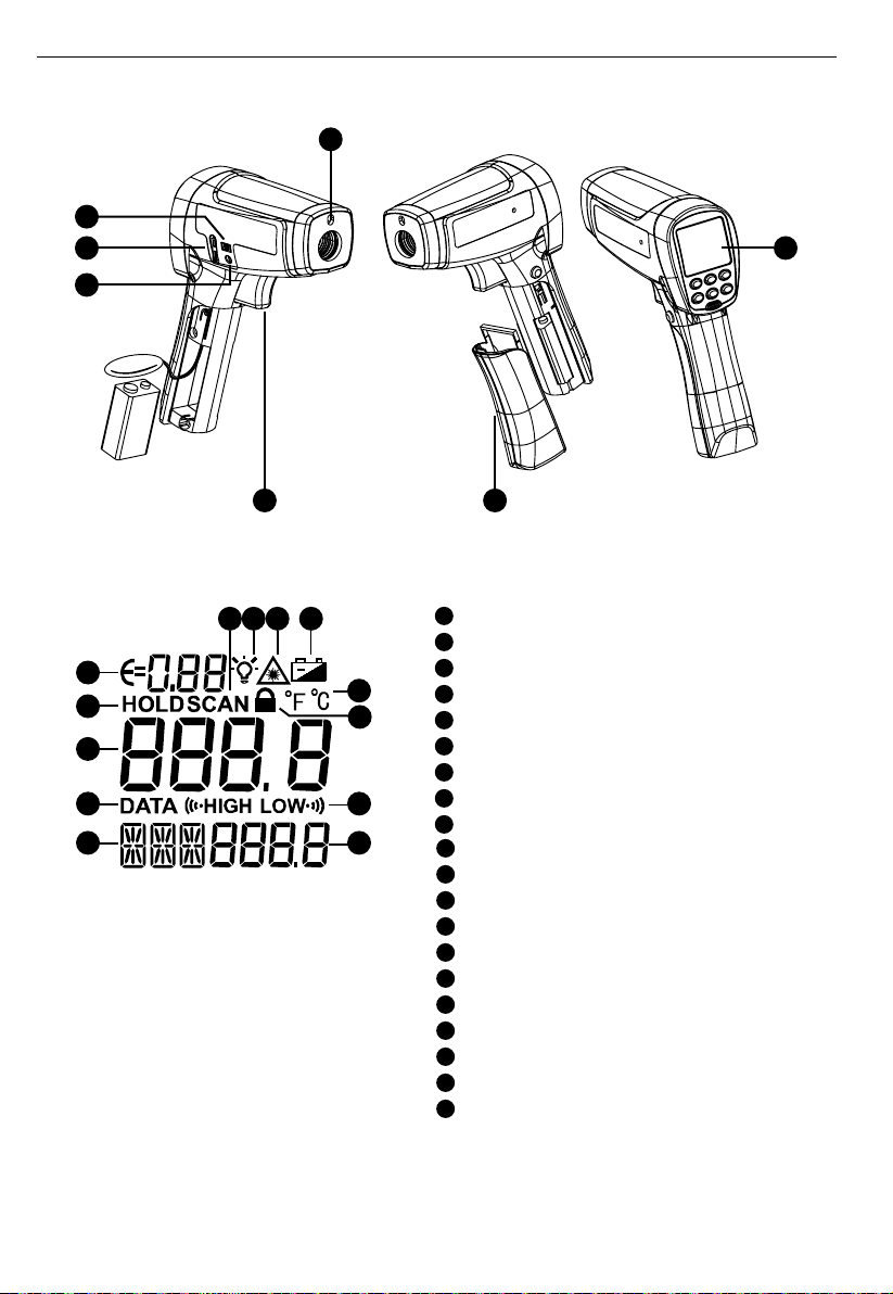
1
5
6
7
2 3
Laser aperture
1
Trigger
2
Battery cover
3
Display
4
USB connector
5
K-type thermocouple connector
6
Power adaptor connector (for optional accessory)
7
Laser “ON” symbol
8
Display backlight
9
10
Measurement lock (continuous measurement)
11
Temperature unit (Celsius / Fahrenheit)
12
8 seconds auto display hold
13
Making measurement (pulling the trigger)
14
Built in memory up to 99 points
15
Programmable high and low alarm
16
Low battery indicator
17
Primary display
18
Secondary display
19
Emissivity (adjustable from 0.10 to 1.00)
20
MAX, MIN, DIF, AVG temperature values
HAL, LAL temperature setting
DATA point selection
T-C K-type thermocouple measurement
19
12
17
14
20
1613
89
11
10
15
18
4
2
Page 7

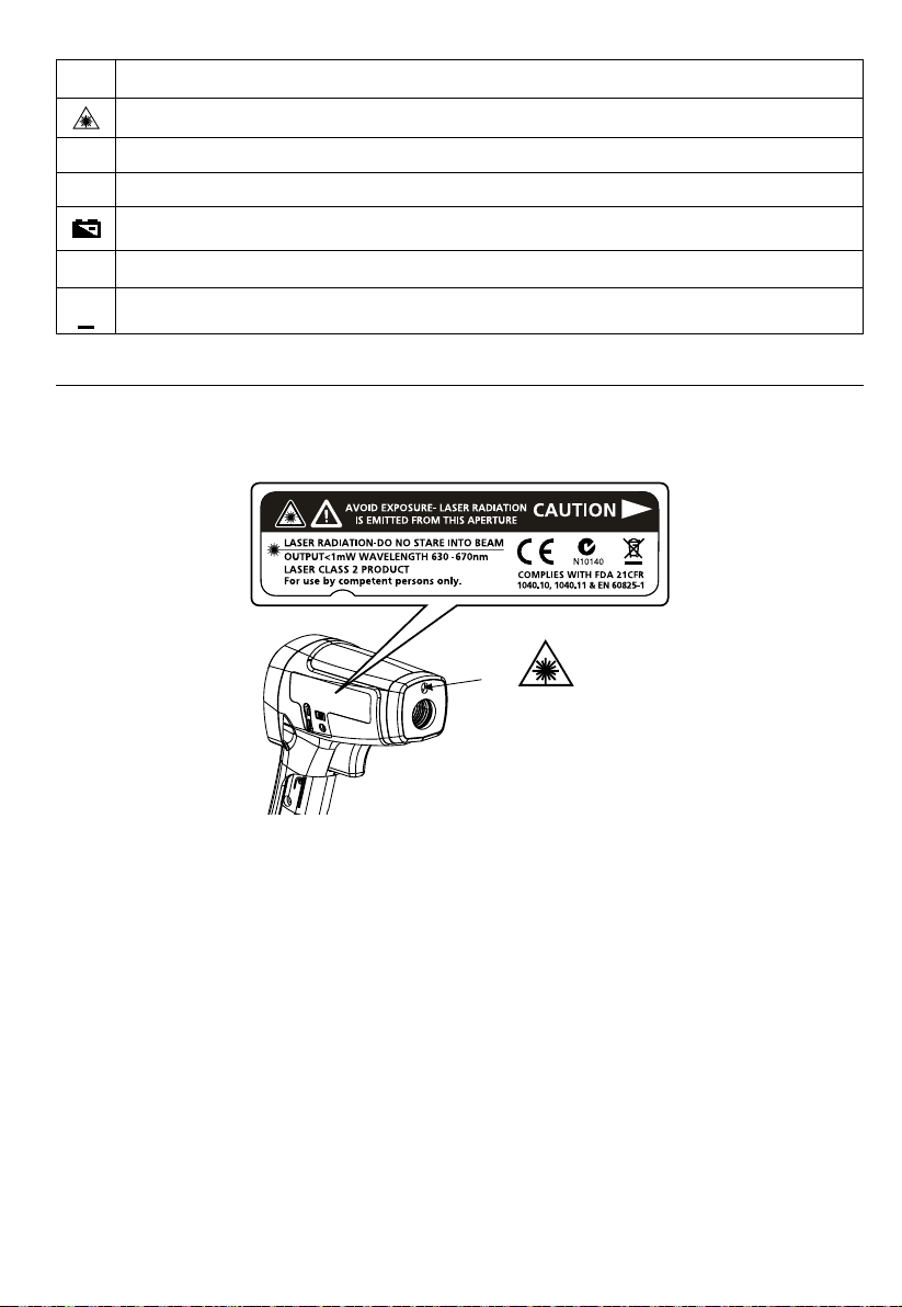
SYMBOLS
Caution! Refer to the explanation in this Manual.
Warning! Laser light. Do not stare into laser beam.
Celsius.
°C
Fahrenheit.
°F
Battery indication.
Complies with European Directives.
Do not dispose of this product as unsorted municipal waste.
Contact a qualified recycler.
SAFETY INFORMATION
The instrument complies with:
EN 61010-1 General Safety
EN 60825-1 Laser Safety
EN 61326-1 Electromagnetic Emissions and Susceptibility
Warning
• Do not stare into laser beam.
• Do not point laser directly at eye or indirectly off reective surfaces.
• For use by competent persons only.
• Replace the batteries as soon as the low-battery indicator appears.
• Do not use the thermometer if it operates abnormally.
• Do not operate the thermometer around explosive gas, vapor, or dust.
• To avoid a burn hazard or re, know that reective objects may be much hotter than the indicated
temperature reading.
• Do not leave the thermometer on or near objects of high temperature.
• If the thermometer is used in a manner not specied by this manual, the protection provided by the
thermometer may be impaired or may result in hazardous laser radiation exposure.
Cautions
To avoid damaging the thermometer under measurement, protect them from the following:
• EMF (electro-magnetic elds) from arc welders, induction heaters
• Static electricity
• Thermal shock (caused by large or abrupt ambient temperature changes — allow 30 minutes for instrument to
stabilize before use)
• Do not leave the thermometer on or near objects of high temperature
3
Page 8

UNPACKING AND INSPECTION
Your shipping carton should include:
1 Thermometer (IR-750 / IR-750-EUR)
1 USB cable
1 K-type thermocouple probe
1 Carrying case
1 Hard carrying case
1 9V battery (installed)
1 Users manual
If any of the items are damaged or missing, return the complete package to the place of purchase for an
exchange.
FEATURES
The Amprobe IR-750 / IR-750-EUR, a precision performance 50:1 spot to distance ratio infrared thermometer,
offers unparalleled accuracy and response time with a temperature measurement range of -58°F to 2822°F
or -50°C to 1550°C. The IR-750 / IR-750-EUR is perfect for demanding quality and process control applications
with extremely high accuracy and distance to spot ratio. The IR-750 / IR-750-EUR also features 99 data points
recognition, thermocouple inputs, and USB download for advanced HVAC/R, electrical, industrial maintenance,
automotive as well as quality control and fire prevention applications.
• 50:1 Distance to Spot ratio
• Temperature range of 0°F to -58°F to 2822°F or -50°C to 1550°C
• Precision accuracy and rapid response time
• Laser pointer, backlit dual LCD Display
• Auto display hold and MAX/MIN memory
• Adjustable emissivity for measuring a variety of materials
• 99 Memory locations and PC download cable included
HOW THE THERMOMETERS WORK
Infrared thermometers measure the surface temperature of an object. The thermometer’s optics sense emitted,
reflected, and transmitted energy, which is collected and focused onto a detector. The unit’s electronics translate
the signal into a temperature reading which the unit displays .
OPERATING THE THERMOMETER
Temperature Measurement
The thermometer will turn on when you pull the trigger and also features an auto-off function that
automatically powers down the thermometer after 8 seconds of inactivity.
To measure temperature, point the thermometer at an object and pull the trigger. You can use the laser pointer
to help aim the thermometer. Pull and hold the trigger when measuring the target surface. When release the
trigger, the display will hold the reading for 8 seconds. Be sure to consider distance-to-spot size ratio and field of
view. The laser is used for aiming only and is not related to temperature measurement.
4
Page 9
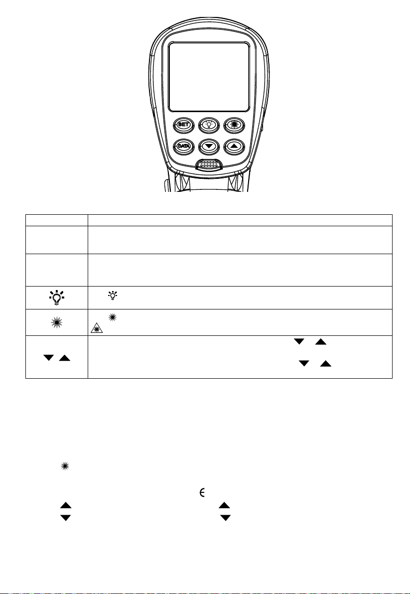
Rotary Switch Positions
Button Description
YELLOW
button
SET
/
Press YELLOW button to toggle between MAX, MIN, DIF, AVG, HAL, LAL, DATA and
T-C options. When the Thermometer goes into sleep mode, press MODE to turn the
thermometer ON again and it displays the last measurement result.
Press to enter set-up mode stepping through Emissivity, Trigger Lock and Switching °C/°F
set-up.
Details refer to the below Emissivity, Trigger Lock and °C / °F set-up.
to turn the display backlight ON or OFF.
Press
Selectable two level of display backlight to adapt different lighting conditions.
Press to turn the laser light ON or OFF.
symbol on the display Indicates laser light is ON.
When the thermometer enters the setup up mode (SET), press or to select a set-up
option (Emissivity, Trigger lock, Switching °C / °F).
When the thermometer enters HAL, LAL and DATA mode, press
option (Emissivity, Trigger lock, Switching °C / °F).
or to select a set-up
Laser
Caution
To avoid injury, do not point the laser directly at eye or indirectly off reflective surfaces.
The thermometer is equipped with a laser used for aiming purposes only. The laser turns off when the trigger
is released.
To enable or disable the laser:
1. Press
button to enable or disable the laser. Symbol appears on the display when laser is enabled.
Emissivity set-up
1. Press SET button to select Emissivity set-up, icon is blinking on the display
2. Press
3. Press
4. Press MODE button to complete the setting and exit Emissivity set-up, or press SET button to complete the setting
Note: Default emissivity is 0.95.
to increase the value by 0.01. Press and hold for quick setting. The maximum value is 1.00.
to decrease the value by 0.01. Press and hold for quick setting. The minimum value is 0.01.
and continue setting for Trigger Lock.
5
Page 10
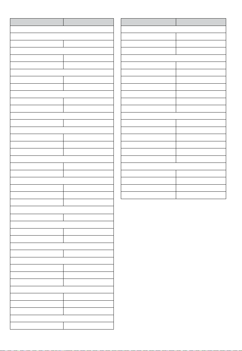
Table of Surface Emissivity
Measure Surface Switch Setting
METALS
Aluminum
Oxidized 0.2 – 0.4
Alloy A3003
Oxidized 0.3
Roughened 0.1 – 0.3
Brass
Burnished 0.3
Oxidized 0.5
Cooper
Oxidized 0.4 – 0.8
Electrical Terminal Blocks 0.6
Haynes
Alloy 0.3 – 0.8
Inconel
Oxidized 0.7 – 0.95
Sandblasted 0.3 – 0.6
Electoropolished 0.15
Iron
Oxidized 0.5 – 0.9
Rusted 0.5 – 0.7
Iron Cast
Oxidized 0.6 – 0.95
Unoxidized 0.2
Molten 0.2 – 0.3
Iron Wrought
Dull 0.9
Lead
Rough 0.4
Oxidized 0.2 – 0.6
Molydbenum
Oxidized 0.2 – 0.6
Nickel
Oxidized 0.2 – 0.5
Platinum
Black 0.9
Steel
Cold-Rolled 0.7 – 0.9
Ground Sheet 0.4 – 0.6
Polished Sheet 0.1
Zinc
Oxidized 0.1
Measure Surface Switch Setting
NON-METALS
Asbestos 0.95
Asphalt 0.95
Basalt 0.7
Carbon
Unoxidized 0.8 – 0.9
Graphite 0.7 – 0.8
Carborundum 0.9
Ceramic 0.95
Clay 0.95
Concrete 0.95
Cloth 0.95
Glass
Plate 0.85
Gravel 0.95
Gypsum 0.8 – 0.95
Ice 0.98
Limestone 0.98
Paper (any colour) 0.95
Plastic
Opaque 0.95
Soil 0.9 – 0.98
Water 0.93
Wood, (natural) 0.9 – 0.95
6
Page 11
Trigger Lock
The thermometer trigger can be locked on for continuous measurement.
To lock the trigger:
1. Press SET button to select Trigger Lock set-up, icon
2. Press
3. Press YELLOW button to complete the setting and exit Trigger Lock set-up, or press SET button to complete the
or to select ON or OFF.
setting and continue setting for °C / °F.
is blinking on the display
°C / °F Set-up
1. Press SET button to select °C / °F set-up, icon °C or °F is blinking on the display
2. Press
3. Press YELLOW button to complete the setting and exit °C / °F set-up.
or to select °C or °F.
MAX, MIN, DIF, AVG
The thermometer can measure maximum (MAX), minimum (MIN), differential (DIF) or average (AVG)
temperatures each time a reading is taken. These values are available for infrared measurements.
1. Press YELLOW button until MIN or MAX or AVG or DIF appears on the display
2. Pull and hold the trigger while aiming at the target surface.
3. The value will show on secondary display.
High Alarm (HAL) and Low Alarm (LAL)
The thermometer has a programmable high and low alarm to designate high or low readings depending on
the thresholds entered. When the alarm level is reached, an alarm will sound. This feature is not available when
measuring by thermocouple.
To set either the high or low alarm:
1. Press YELLOW button to select HAL or LAL option.
2. Press
3. Press SET button to complete the setting. Symbol
To turn off the high or low alarm:
1. Press YELLOW button to select HAL or LAL option.
2. Press SET button. Disappearance of Symbol
or to adjust the threshold value.
or
or
will appear on the display.
on the display indicates high or low alarm is off.
DATA Memory
The thermometer has 99 points data storage and the stored data can be downloaded via IR-750 /
IR-750-EUR software. To save the data:
1. Press YELLOW button to select DATA option.
2. Press
3. Pull and hold the trigger while aiming at the target surface, press DATA button to save the measurement value.
or to select data record number
You can also save the measurement value within 8 seconds of display hold after releasing the trigger.
K-Type Thermocouple Measurement
To avoid electrical shock or personal injury, do not connect the thermocouple contact probe to live
electrical circuits.
The thermometer comes with a bead K-type thermocouple probe.
K-type thermocouple is connected to the thermometer via TC-K input connector located on right side of
the thermometer. The probe can be used simultaneously while the thermometer is taking non-contact
measurements.
1. Press YELLOW button to enter T-C mode. The display shows OL before the measurement is made.
2. Connect the K-type thermocouple to the thermometer via TC-K input connector located on right side of
the thermometer. Press the trigger to start measuring. Secondary display shows the measurement reading.
3. Release the trigger, the reading is kept on display (display hold: 8 seconds)
7
Page 12

Locating a Hot or Cold Spot
To find a hot or cold spot, aim the thermometer outside the target area. Then, slowly scan across the area with
an up and down motion until you located the hot or cold spot.
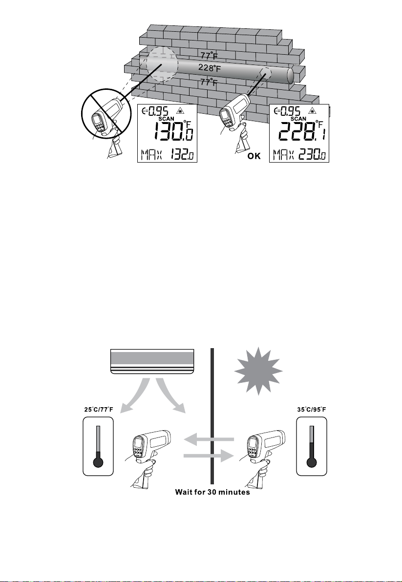
Distance and Spot Size
As the distance (D) from the target being measured increases, the spot size (S) of the area measured by the
instrument becomes larger. The spot size indicates 90% encircled energy.
Field of View
Make sure that the target is larger than the spot size. The smaller the target, the closer you should be to it.
8
Page 13
Emissivity
Emissivity describes the energy-emitting characteristics of materials. Most organic materials and painted or oxidized
surfaces have an emissivity of about 0.95.
If possible, to compensate for inaccurate readings that may result from measuring shiny metal surfaces, cover
the surface to be measured with masking tape or flat black paint (<150°C / 302°F ) and use the high emissivity
setting. Allow time for the tape or paint to reach the same temperatures as the surface beneath it. Measure the
temperature of the tape or painted surface.
If you cannot use paint or use tape, then you could improve the accuracy of your measurements with the
emissivity selector. Even with emissivity selector, it can be difficult to get a completely accurate infrared
measurement of a target with a shiny or metallic surface.
The thermometer allows you to adjust the emissivity for the type of surface you’re trying to measure the
temperature of. Use a different setting for your application by referring to the Table of Surface Emissivity.
Reminders
1. Changes of surrounding ambient temperature can result in inaccurate reading, allow time for the
instrument to adopt the change of ambient temperature before use. Specified accuracy applies after 30
minutes when the instrument changes to a different temperature environment an inaccurate.
2. The instrument cannot measure through transparent surfaces such as glass. It will measure the surface
temperature of the glass instead.
9
Page 14

3. See Table of Surface Emissivity for use in measuring shiny or polished metal surfaces (stainless steel,
aluminum, etc.).
4. Steam, dust, smoke, etc., can prevent accurate measurement by obstructing the instrument’s optics.
TYPICAL MEASUREMENTS
This section describes a variety of measurements often performed by technicians.
Reminder:
• User could select to turn on or off the backlight and laser whenever you are making readings with the
thermometer.
• Relatively high emissivity normally means emissivity setting of about 0.95.
• Relatively low emissivity normally means emissivity setting of about 0.30.
• When user cannot identify the emissivity of the object to be measured, user could cover the surface to be
measured (temperature >150°C) with black electric tape (emissivity of about 0.95). Allow time for the tape
to reach the same temperature as the object to be measured. Measure and record the temperature of the
tape.
Aim the thermometer to the object to be measured, adjust the emissivity setting to make it as the same temperature
as the tape. At this time, the thermometer emissivity setting is close to the emissivity of the object to be measured,
measurement can be taken.
Testing Contactors (Starters)
1. Press SET to select emissivity. Press / to select relatively low emissivity for bright contacts, or 0.7 mid
level for darkened contacts.
2. Press YELLOW button to select MAX.
3. Measure line and load side of one pole without releasing trigger.
4. A temperature difference between the line and load sides of a pole indicate increased resistance of one
point and a contactor may be failing.
Testing Enclosed Relays
1. Press SET and then press / to set emissivity to relatively low for un-insulated connectors or relatively
high for plastic encased relays or for Bakelite enclosed relays or insulated connectors.
2. Press YELLOW button to select MAX.
3. Start to scan.
4. Measure the relay casing, looking for hot spots.
5. Measure electrical connections on relay terminals looking for hot spots.
10
Page 15

Testing Fuses and Buss Connections
1. Press SET and then press / to set emissivity to relatively high for paper covered fuse body or
insulated connections.
2. Press YELLOW button to select MAX.
3. Scan the paper covered length of fuse.
4. Without releasing the trigger, scan each fuse. Unequal temperatures between fuses may indicate voltage or
amperage imbalance.
5. Press SET and then press / to set emissivity to relatively low, for metal fuses and caps and insulated
buss connections.
6. Press MODE to select MAX.
7. Scan each end cap on each fuse.
Note: Unequal temperatures or a high temperature indicates loose or corroded connection through the fuse
buss spring clip
Testing Electrical Connections
1. Press SET and then press / to set emissivity to relatively low for
un-insulated connectors or buss connections or relatively high for insulated connections.
Note: Conductors are typically smaller than the thermometer’s spot size.
If the spot size is bigger than the connector, the temperature reading is the average within the spot.
2. Scan the conductor, moving toward direction of electrical connector (quick connector, wire nut, buss
connection, etc.).
Scanning Walls for Air Leaks or Insulation Deficiencies
1. Turn off heating, cooling, and blower.
2. Press SET to select emissivity. Press
window surfaces.
3. Press YELLOW button to select MIN when opposite side of wall is at lower temperature and or select MAX
when opposite side of wall is at higher temperature.
4. Measure an interior partition wall surface temperature.
5. Do not release the trigger. Record this temperature as your baseline (or benchmark) for a “perfectly”
insulated wall.
6. Face the wall to be scanned. Stand 1.5m away to scan a 4cm spot on the wall.
7. Scan horizontal rows of wall from top to bottom, or horizontal rows of ceiling from wall to wall. Look for
greatest deviations from baseline temperature to identify problems. This completes the insulation test scan.
Turn on the blower (no heat, no cooling) and retest. If test results with the blower on are different than results
with the blower off, this may indicate air leaks in conditioned envelope walls. The air leaks are caused by duct
leaks that create a pressure differential across the conditioned space envelope.
/ to select emissivity relatively high for painted surfaces or
Testing Bearings
Warning
To avoid injury when testing bearings:
1. Do not wear loose clothing, jewelry, or anything around neck when working around moving parts such as
motors, belts, blower, and fans.
2. Make sure an electrical disconnect is within reach and operating correctly and freely.
3. Do not work alone.
Note: It works best to compare two similar motors operating similar loads
11
Page 16

1. Press SET and then press
2. Press SELECT to select MAX.
3. Enable motor and allow it to reach steady state operating temperatures.
4. Disable the motor if possible.
5. Measure the two motor bearing temperatures.
6. Compare the two motor bearing temperatures. Unequal temperatures or a high temperature can indicate
a lubrication or other bearing problem that is resulting from excess friction.
7. Repeat the sequence for the blower bearings.
/ to select relatively high emissivity.
Testing Belts and Sheaves
1. Press SET and then press / to select relatively high emissivity.
2. Press SELECT to select MAX.
3. Enable the motor and allow it to reach a steady state operating temperatures.
4. Aim the thermometer at the surface to be measured.
5. Start recording temperature.
6. Slowly move the thermometer up the belt toward second sheave.
• If belt is slipping, sheave temperature will be high from friction.
• If belt is slipping, belt temperature will remain high between sheaves.
• If belt is not slipping, belt temperature will reduce between sheaves.
• If inner surfaces of sheaves are not a true “V” shape, this indicates belt slippage and will continue to
operate at elevated temperatures until sheave is replaced.
• Sheaves must be properly aligned (include “pitch & yaw”) for belt and sheaves to operate at
appropriate temperatures. A straight edge or taut string, can be used to check alignments.
• Motor sheave should operate at a temperature consistent with blower sheaves.
• If motor sheave is at a higher temperature at motor shaft than at outer circumference, belt is probably
not slipping.
• If outer circumference of sheave is at higher temperature than sheave at motor shaft, then belt is probably
slipping and sheaves may be misaligned.
Checking Hydronic Radiant Heat Applications
1. Press SET and then press / to select relatively high emissivity.
2. Press YELLOW button to select MAX.
3. To locate radiant heat tubes in floor, temporarily elevate the loop temperature to create hotter spots for
identifying tubing runs.
4. Before releasing trigger, press YELLOW button to toggle between MIN, MAX, DIF floor temperatures and
record the temperature for future comparison and trending under similar conditions.
Measuring Grill, Register, or Diffuser Discharge Temperature
1. Press SET and then press / to select relatively high emissivity.
2. Aim the thermometer at the discharge air grille, register, or diffuser.
3. Measure discharge temperature.
4. Release trigger to freeze the temperature reading for 8 seconds and record this temperature.
5. Grille, register, or diffuser temperature should be equivalent to discharge temperature at the air handler.
12
Page 17
Checking for Blockage in Air-To-Air Evaporator or Condensers
1. Remove panels to gain access to coil return bends or hairpins.
2. Press SET and then press
3. Start the refrigeration system.
4. Aim the thermometer at coil turn bends/hairpins.
5. Start recording temperature.
6. Take temperature of each return bend/hairpin.
• All evaporator return bends/hairpins should be at or slightly above evaporator saturation temperature from the
pressure/temperature chart.
• All condenser return bend/hairpins should be at or slightly less than condenser saturation temperature.
• If a group of return bends/hairpins do not conform to expected temperatures, that indicates a blocked
or restricted distributor or distributor tube.
/ to select relatively high emissivity for copper tube.
OPERATING IR-750 / IR-750-EUR SOFTWARE
System Prerequisites
Recommended configuration
Processor Pentium® 4 or higher with support of all customary operating systems
Operating system Microsoft Windows® 2000 / XP / Vista / Win7
Memory 512 MB RAM or higher
Monitor VGA (1024 x 768)
Drive CD-ROM
Input device Mouse or compatible
Interface USB for data transmission
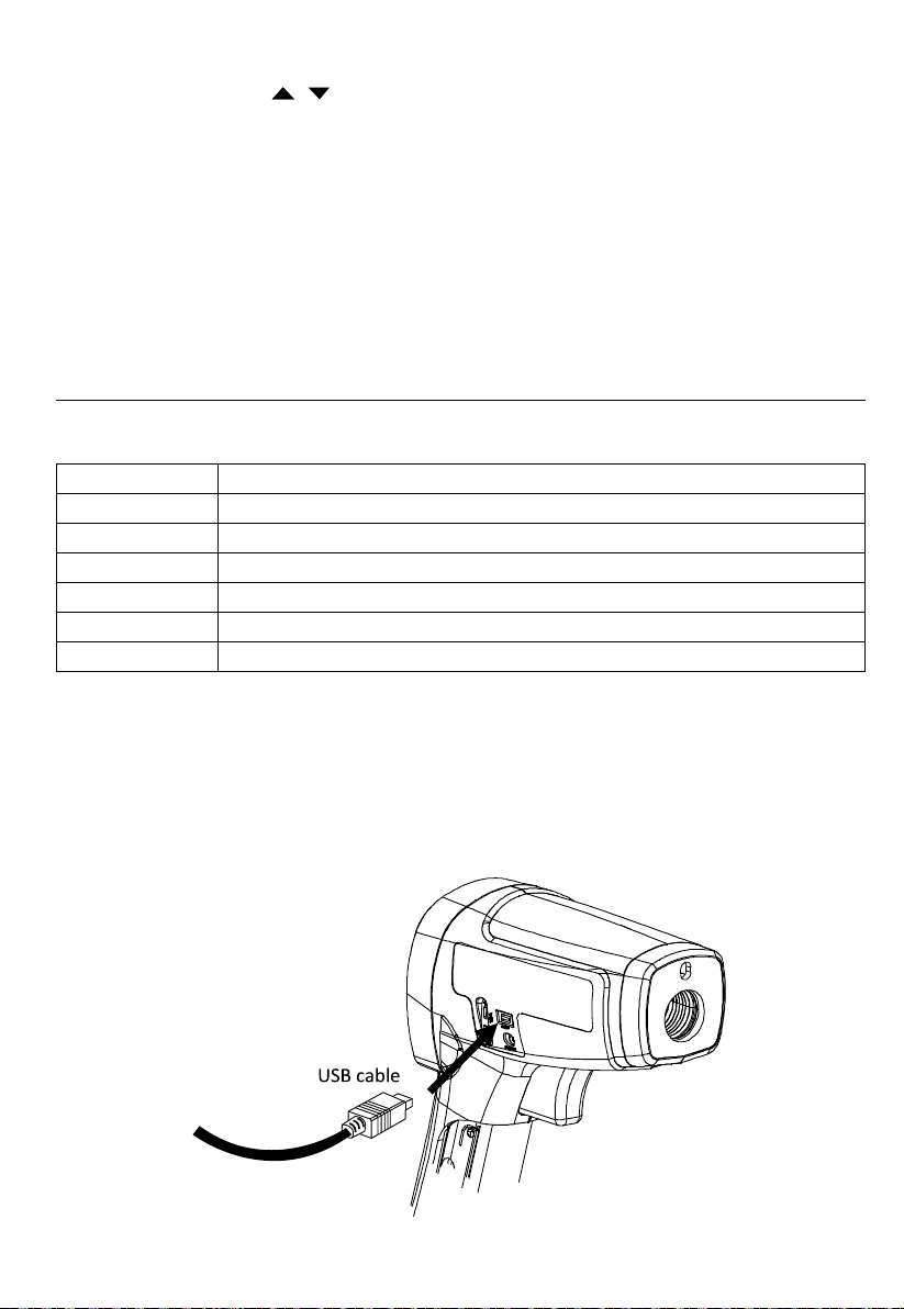
Install IR-750 / IR-750-EUR Software
• Insert the provided CD disk into CD-ROM drive.
• Double-click “IR-750_VX.XX.exe” (X can be 0 to 9 or blank,
indicating the software version)
• The pop-up windows will guide you through the program setup process.
Connecting USB cable to IR-750 / IR-750-EUR Thermometer
13
Page 18
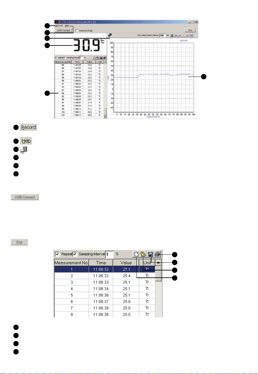
Main Screen
1
2
3
4
6
5
command enables you to create New, Save file and set the numbers of measurement (1000, 5000,
1
10000, 50000, 100000 or limitless).
command enables you to view the software operation instructions.
2
Blinking indicates IR-750 / IR-750-EUR is connected to the software
3
Main display screen of measurement
4
Secondary display screen for measurement data
5
Measurement data in graph
6
Using Program
Connect” blinking indicates that the IR-750 / IR-750-EUR Thermometer is successfully connected to the
PC and that the thermometer will automatically start taking measurements. The primary display screen shows
current measurement temperatures and the secondary display screen shows all measurement data.
Download Data enables you to download temperature measurements saved in IR-750 / IR-750-EUR Thermometer.
Tick “Download Data” and then click “USB Connect”; the saved data will automatically upload to your PC and
display on secondary display.
button enables you to connect to IR-750 / IR-750-EUR thermometer and start measurement. “USB
Exit and close the program
1
Print data
2
Save data (*.txt, *.xls, *.xml)
3
Open files (*.txt, *.xls, *.xml)
Deleting current data and create a new data.
4
1
2
3
4
14
Page 19
Repeat: Tick to display every measurement with the interval you set. Un-tick “Repeat”, the secondary display will
only show measurement results that are different from the last measured temperature. The graph display will
show complete measurement results in the graphics despite whether “Repeat” is ticked or un-ticked.
Sampling Interval allows you to set the sampling intervals of measurement ( 1 to 9999 seconds).
Note: When measurement data reaching to 10000 sets (measurement number), a warning message will pop up
and stop measurements. Save or clear the measurement data before continuing next measurements.
1
2
3
4
5
6
7
1
Last page
2
Next page
3
Current page
4
Previous page
5
First page
6
Save graph in current page as *.bmp
7
Set numbers of measurement data on graph display
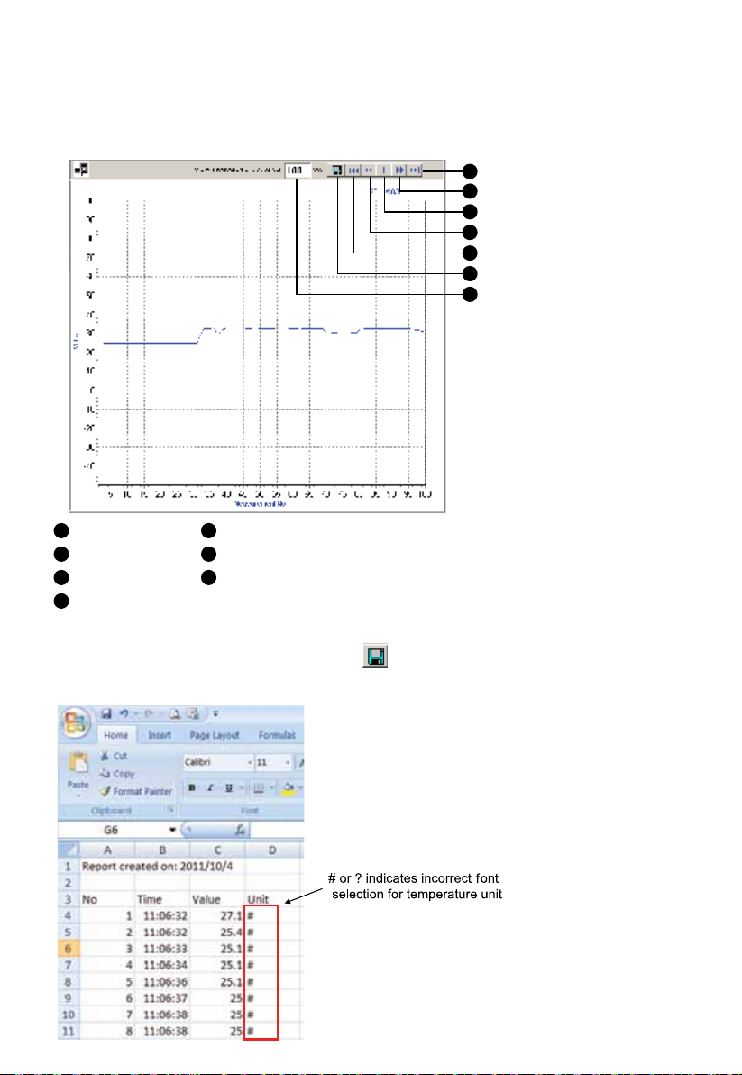
Test Report
Test data can be saved as *.txt, *.xls, *.xml by clicking button. When opening data report, make sure
selecting font format as Amprobe-A1 or Amprobe-A2 in “Unit” column in order to display correct temperature
unit °C or °F.
15
Page 20

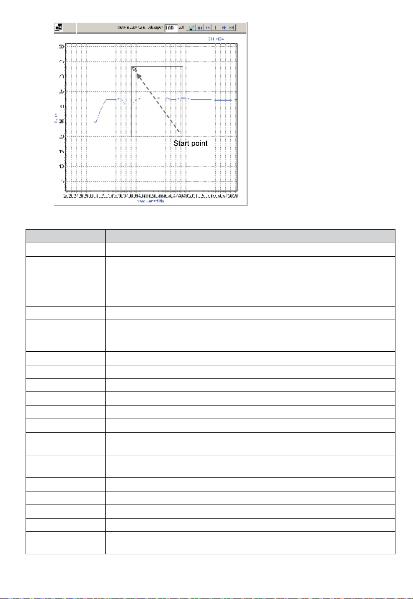
Zoom In Selected Graph
To enlarge the particular part of the graph, use the mouse pointer to select area from upper-left point to lower-right
point.
You can use button to save the selected enlarged graph.
To resume to its original full view, use the mouse pointer to select any area on the graph from lower-right point
to upper-left point.
16
Page 21
DETAILED SPECIFICATIONS
Feature IR-750 / IR-750-EUR
Temperature Range -50°C to 1550°C (-58°F to 2822°F)
Accuracy (assumes
ambient operating
temperature of 21°C
to 25°C (70°F to 77°F))
Repeatability ±0.5% of reading or ±0.5°C (±1°F), whichever is greater (Typical)
Display Resolution 0.1°C / 0.1°F of reading < 999.9
Spectral Response 8µm to14µm
Laser Sighting Single point laser
Laser Power Output > 1mW Class 2, wavelength 630 to 670nm
Response Time (95%) 250ms
Distance to Spot (D:S) 50:1
Minimum Spot Size 19mm
Emissivity Digitally adjustable from 0.10 to 1.00 by 0.01.
Ambient Operating
Temperature
Relative Humidity 0% to 75% non-condensing
Storage Temperature -20°C to 65°C / -4°F to 150°F (Battery not installed)
Temperature Display °C or °F selectable
Display Hold 8 sec
MAX/MIN
Temperature Display
>0°C to 1550°C (>32°F to 2822°F): ±1.8% or ±1.8°C (±4°F),
whichever is greater (Typical)
>-35°C to 0°C (-31°F to 32°F): ±1.8%+1°C (2°F) or ±2.8°C (±6°F),
whichever is greater (Typical)
-50°C to -35°C (-58°F to -31°F): not specified (for reference only)
0.2°C / 0.2°F of reading below 10°C (50°F)
1°C / 1°F of reading > 999.9
Pre-set emissivity is 0.95
0°C to 50°C
32°F to 120°F
√
17
Page 22
DIF/AVG Temperature
Display
USB Interface √
Data Storage 99
Programmable High
and Low Alarm
K-Type Thermocouple
Measurement
Dual LCD Display √
LCD Backlit √
Low Battery Indication
Tripod Mount √
Power 9V 6F22 alkaline battery or by Amprobe EPS-700-US (US plug) or EPS-700-EUR (European
Battery Life
Dimension (H x L x W) Approx.183 x 147 x 57 mm (7.2 x 5.8 x 2.3 in)
Weight Approx.345 g (0.76 lb) with battery installed
Optional Accessory Power adaptor EPS-700-US (US plug), EPS-700-EUR (European plug)
√
√
√
√
plug) power adaptor
10 hours with laser and backlight on
30 hours with laser and backlight off
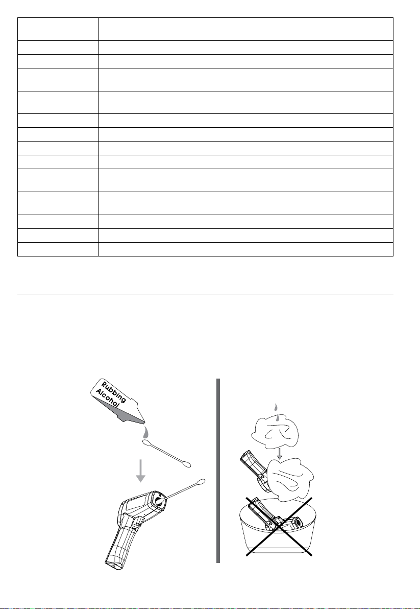
MAINTENANCE
Lens Cleaning: Blow off loose particles using clean compressed air. Gently brush remaining debris away with a
camel hair brush. Carefully wipe the surface with a moist cotton swab. The swab may be moistened with water
or rubbing alcohol.
NOTE: DO NOT use solvents to clean the plastic lens.
Case Cleaning: Use soap and water on a damp sponge or soft cloth.
Caution!
Do not submerge the unit in water.
18
Page 23
TROUBLE SHOOTING
Code Problem Action
OL Target temperature is over range Select target within specifications
-OL Target temperature is under range Select target within specifications
Low battery
Battery indication
Blank display Possible dead battery Check and/or replace battery
Laser does not work
Beeper beeps
continuously
1. Low or dead battery
2. Ambient temperature above 40°C (104°F)
Check if high/low alarm has been set and if
the measurement value is over the limit
Check and/or replace battery
1. Replace battery
2. Use in area with lower ambient
temperature
Reset high/low alarm setting or
cancel the limit setting
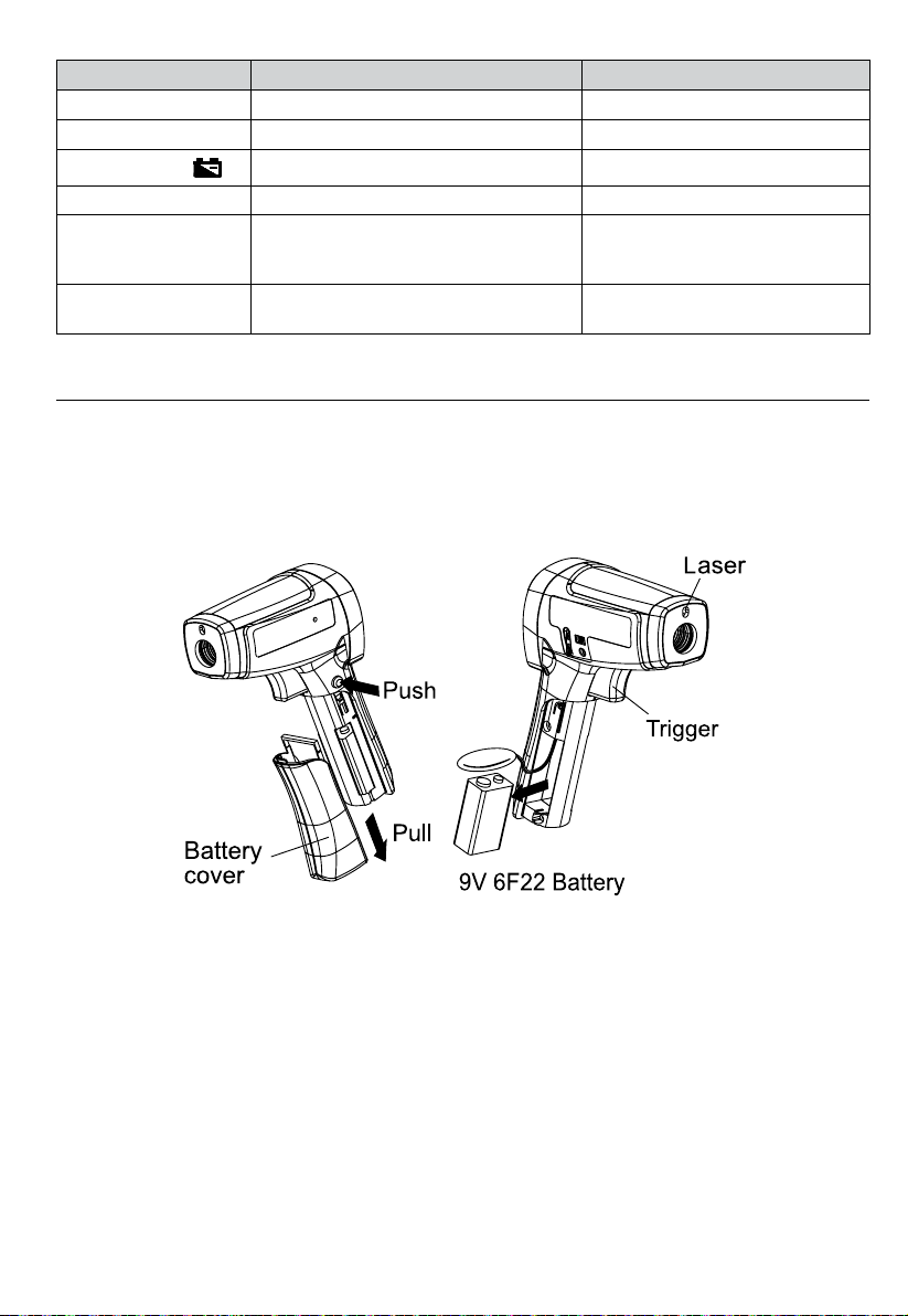
BATTERY REPLACEMENT
To install or change one 9V battery (see below):
1. Push the button and pull the handle downward to open battery cover.
2. Install the battery noting its correct polarity.
3. Re-install the battery cover.
Battery: 9V 6F22 alkaline battery or equivalent
19
Page 24

Page 25

IR-750
IR-750-EUR
Thermomètre IR 50:1 avec mémoire
Mode d’emploi
Français
11/2013, 4279850 B
©2013 Amprobe Test Tools.
Tous droits réservés. Imprimé en Chine.
Page 26

Limites de garantie et de responsabilité
Amprobe garantit l’absence de vices de matériaux et de fabrication de ce produit pendant une période d’un
an prenant effet à la date d’achat, sauf disposition contraire prévue par la loi. Cette garantie ne s’applique
pas aux fusibles, aux piles jetables ni à tout produit mal utilisé, modié, contaminé, négligé ou endommagé
par accident ou soumis à des conditions anormales d’utilisation et de manipulation. Les revendeurs n’ont pas
l’autorisation de prolonger toute autre garantie au nom d’Amprobe. Pour bénéficier de la garantie, renvoyez
le produit accompagné d’un justicatif d’achat auprès d’un centre de services agréé par Amprobe Test Tools ou
d’un distributeur ou d’un revendeur Amprobe. Voir la section Réparation pour tous les détails. LA PRÉSENTE
GARANTIE EST LE SEUL ET EXCLUSIF RECOURS DE L’UTILISATEUR TOUTES AUTRES GARANTIES, EXPLICITES,
IMPLICITES OU STATUTAIRES, NOTAMMENT LE CAS ÉCHÉANT LES GARANTIES DE QUALITÉ MARCHANDE OU
D’ADAPTATION À UN OBJECTIF PARTICULIER SONT EXCLUES PAR LES PRÉSENTES. LE FABRICANT NE SERA EN
AUCUN CAS TENU RESPONSABLE DE DOMMAGES PARTICULIERS, INDIRECTS, ACCIDENTELS OU CONSÉCUTIFS,
NI D’AUCUNS DÉGATS OU PERTES DE DONNÉES, SUR UNE BASE CONTRACTUELLE, EXTRA-CONTRACTUELLE
OU AUTRE. Étant donné que certaines juridictions n’admettent pas les limitations d’une condition de garantie
implicite ou l’exclusion ou la limitation de dégâts accidentels ou consécutifs, il se peut que les limitations et les
exclusions de cette garantie ne s’appliquent pas à votre cas.
Réparation
Tous les outils de test renvoyés pour être réparés au titre de la garantie ou pour étalonnage doivent être
accompagnés des éléments suivants : nom, raison sociale, adresse, numéro de téléphone et justicatif d’achat.
Ajoutez également une brève description du problème ou du service demandé et incluez les cordons de test avec
l’appareil. Les frais de remplacement ou de réparation hors garantie doivent être acquittés par chèque, mandat,
carte de crédit avec date d’expiration, ou par bon de commande payable à l’ordre de Amprobe® Test Tools.
Remplacements et réparations sous garantie – Tous pays
Veuillez lire la déclaration de garantie et vérifier les piles avant de demander une réparation. Pendant la période
de garantie, tout outil de test défectueux peut être renvoyé auprès de votre distributeur Amprobe® Test Tools
pour être échangé contre un produit identique ou similaire. Consultez la section « Where to Buy » sur le site
www.amprobe.com pour obtenir la liste des distributeurs dans votre région. Les appareils sous garantie devant
être remplacés ou réparés au Canada et aux États-Unis peuvent également être envoyés dans un centre de
services Amprobe® Test Tools (voir les adresses ci-dessous).
Remplacements et réparations hors garantie – Canada et États-Unis
Les appareils à réparer hors garantie au Canada et aux États-Unis doivent être envoyés dans un centre de
services Amprobe® Test Tools. Appelez Amprobe® Test Tools ou renseignez-vous auprès de votre lieu d’achat
pour connaître les tarifs en vigueur de remplacement ou de réparation.
Aux États-Unis Au Canada
Amprobe Test Tools Amprobe Test Tools
Everett, WA 98203 Mississauga, Ontario L4Z 1X9
Tél. : 877-AMPROBE (267-7623) Tél. : 905-890-7600
Remplacements et réparations hors garantie – Europe
Les appareils européens non couverts par la garantie peuvent être remplacés par votre distributeur Amprobe®
Test Tools pour une somme nominale. Consultez la section « Where to Buy » sur le site www.amprobe.com pour
obtenir la liste des distributeurs dans votre région.
Adresse postale européenne*
Amprobe® Test Tools Europe
Beha-Amprobe GmbH
In den Engematten 14
79286 Glottertal, Allemagne
Tél. : +49 (0) 7684 8009 - 0
www.amprobe.eu
*(Réservée à la correspondance – Aucune réparation ou remplacement n’est possible à cette adresse. Nos clients
européens doivent contacter leur distributeur.)
Page 27

IR-750 / IR-750-EUR Thermomètre IR 50:1 avec mémoire
TABLE DES MATIÈRES
SYMBOLES .................................................................................................................................................................... 3
CONSIGNES DE SÉCURITÉ ............................................................................................................................................ 3
DÉBALLAGE ET INSPECTION ........................................................................................................................................ 4
FONCTIONNALITÉS ....................................................................................................................................................... 4
FONCTIONNEMENT DES THERMOMÈTRES ................................................................................................................. 4
UTILISATION DU THERMOMÈTRE ................................................................................................................................4
Mesures de température ......................................................................................................................................... 4
Localisation d'un point chaud ou froid .................................................................................................................. 8
Distance et taille du point focal (spot) ................................................................................................................... 8
Champ de visée ........................................................................................................................................................ 8
Émissivité .................................................................................................................................................................. 9
Rappels ..................................................................................................................................................................... 9
MESURES TYPIQUES ..................................................................................................................................................... 10
FONCTIONNEMENT DU LOGICIEL IR-750 / IR-750-EUR ............................................................................................... 13
CARACTÉRISTIQUES ..................................................................................................................................................... 17
ENTRETIEN .................................................................................................................................................................... 18
DÉPANNAGE .................................................................................................................................................................19
CHANGEMENT DES PILES ............................................................................................................................................. 19
1
Page 28

IR-750 / IR-750-EUR Thermomètre IR 50:1 avec mémoire
1
5
6
7
2 3
Ouverture laser
1
Gâchette
2
Couvercle de pile
3
Affichage
4
Connecteur USB
5
Connecteur de thermocouple de type K
6
Connecteur d'adaptateur secteur (pour un accessoire
7
optionnel)
Symbole laser « actif »
8
Rétroéclairage
9
10
Verrouillage de mesure (mesure continue)
11
Unité de température (Celsius / Fahrenheit)
12
Maintien d'affichage automatique de 8 secondes
13
Établissement des mesures (en actionnant la gâchette)
14
Mémoire intégrée de 99 points
15
Alarme haute et basse programmable
16
Témoin de pile faible
17
Fenêtre principale
18
Fenêtre secondaire
19
Émissivité (réglable de 0,10 à 1,00)
20
Valeurs de température MAX, MIN, DIF, AVG
Réglage de température HAL, LAL Sélection des
points de données DATA
Mesure de thermocouple de type T-C K
19
12
17
14
20
1613
89
11
10
15
18
4
2
Page 29
SYMBOLES
Attention ! Se reporter aux explications de ce manuel.
Avertissement ! Lumière laser. Ne pas regarder dans le faisceau laser.
Celsius.
°C
Fahrenheit.
°F
Témoin de pile.
Conforme aux directives européennes.
Ne pas mettre ce produit au rebut parmi les déchets ménagers. Consulter un centre de recyclage
homologué.
CONSIGNES DE SÉCURITÉ
L'instrument est conforme aux normes suivantes :
Sécurité générale EN 61010-1
Sécurité laser EN 60825-1
Émissions et sensibilité électromagnétique EN 61326-1
Ouverture laser
Avertissement
• Ne pas regarder dans le faisceau laser.
• Ne pas pointer directement le laser en direction des yeux, ou indirectement vers des surfaces
rééchissantes.
• Utilisation réservée aux personnes compétentes.
• Remplacer les piles dès que l’indicateur des piles déchargées apparaît.
• Vérier le fonctionnement du thermomètre en mesurant une source de tension connue. Ne pas utiliser le
thermomètre s’il ne fonctionne pas normalement.
• Ne pas utiliser le thermomètre à proximité de gaz explosifs, de vapeurs ou de poussière.
• Pour éviter les risques d’incendie ou de brûlures, ne pas oublier que les objets rééchissants sont souvent
plus chauds que la température indiquée sur le thermomètre.
• Ne pas laisser le thermomètre sur ou à proximité d'objets à température élevée.
• Utiliser le thermomètre en respectant les indications de ce mode d’emploi an de ne pas entraver la
protection intégrée au thermomètre et de pas provoquer d'exposition dangereuse au rayonnement
laser.
Attention
Pour ne pas endommager le thermomètre pendant la mesure, le protéger des éléments suivants :
• CEM (champs électromagnétiques) des soudeurs à l'arc, chauffages à induction
• Électricité statique
• Chocs thermiques (provoqués par des changements de température ambiante importants ou abrupts : laisser
l'appareil se stabiliser 30 minutes avant l'emploi)
• Ne pas laisser le thermomètre sur ou à proximité d'objets à température élevée
3
Page 30

DÉBALLAGE ET INSPECTION
Le carton d’emballage doit inclure les éléments suivants :
1 thermomètre (IR-750 / IR-750-EUR)
1 câble USB
1 sonde thermocouple de type K
1 sacoche de transport
1 étui de transport
1 pile de 9 V (installée)
1 Mode d’emploi
Si l’un de ces éléments est endommagé ou manquant, renvoyez le contenu complet de l’emballage au lieu
d’achat pour l’échanger.
FONCTIONNALITÉS
Le thermomètre Amprobe IR-750 / IR-750-EUR, un thermomètre infrarouge avec un rapport de distance à taille
de point focal de 50:1, offre la meilleure précision de sa classe et un temps de réponse avec une plage de mesure
de températures de -50 °C à 1550 °C (-58 °F à 2822 °F). L'IR-750 / IR-750-EUR est spécialement conçu pour les
applications de contrôle de procédés avec une précision extrêmement élevée de la distance au point focal. Le
thermomètre Amprobe IR-750 / IR-750-EUR propose également la reconnaissance de 99 points de données, des
entrées de thermocouple et le téléchargement par connexion USB pour les applications avancées de CVC/R,
électricité, maintenance industrielle, automobile et le contrôle de la qualité et la prévention des incendies.
• Rapport de distance à taille de point focal 50:1
• Plage de températures de -50 °C à 1550 °C (-58 °F à 2822 °F)
• Précision des mesures et temps de réponse rapide
• Pointeur laser, double afchage LCD rétroéclairé
• Maintien automatique de l'afchage et mémoire MAX/MIN
• Émissivité réglable pour la mesure de divers matériaux
• 99 emplacements mémoire et câble de téléchargement vers PC inclus
FONCTIONNEMENT DES THERMOMÈTRES
Les thermomètres infrarouges mesurent la température de surface d'un objet. L'optique du thermomètre
détecte l'énergie émise, réfléchie et transmise qui est collectée et focalisée sur un détecteur. L'électronique de
l'appareil convertit le signal dans la lecture de température qui apparaît sur l'afficheur.
UTILISATION DU THERMOMÈTRE
Mesures de température
Le thermomètre se met sous tension lorsque vous appuyez sur la gâchette.
Le thermomètre se met hors tension lorsqu'aucune activité n'est détectée pendant 8 secondes.
Pour mesurer la température, pointez le thermomètre sur un objet et actionnez la gâchette. Vous pouvez utiliser
le pointeur laser pour mieux viser avec le thermomètre. Actionnez et maintenez la gâchette pour mesurer la
surface ciblée. Quand vous relâchez la gâchette, l'écran maintient l'affichage de la mesure pendant 8 secondes.
Veillez à respecter la distance par rapport à la taille du point focal et le champ de visée. Le laser n'est utilisé que
pour viser et n'a pas d'incidence sur la mesure de température.
Le thermomètre possède une fonction d'arrêt automatique qui met le thermomètre automatiquement hors
tension après 8 secondes d'inactivité. Actionnez la gâchette pour mettre le thermomètre sous tension.
4
Page 31

Positions du sélecteur rotatif
Bouton Description
Bouton
JAUNE
SET
Appuyer sur le bouton JAUNE pour basculer entre les options MAX, MIN, DIF, AVG, HAL, LAL,
DATA et T-C. Lorsque le thermomètre passe en mode de veille, appuyer sur MODE pour remettre
le thermomètre de nouveau sous tension pour qu'il afche la dernière mesure obtenue.
Appuyer sur cette touche pour passer en mode de configuration, soit alternativement pour
définir l'émissivité, verrouiller le déclenchement des mesures et sélectionner °C / °F. Les détails
ci-dessous renvoient à la configuration de l'émissivité, au verrouillage du déclenchement des
mesures et à la sélection °C / °F.
Appuyer sur
sélectionnables pour s'adapter aux différentes conditions d'éclairage.
Appuyer sur pour allumer ou éteindre la lumière laser. Le symbole sur l'affichage indique
que la lumière laser est allumée.
Quand le thermomètre passe en mode de conguration (SET), appuyer sur ou sur
pour sélectionner une option de configuration (émissivité, verrouillage du déclenchement des
mesures et sélection °C / °F).
/
Quand le thermomètre passe en mode HAL, LAL et DATA, appuyer sur
sélectionner une option de configuration (émissivité, verrouillage du déclenchement des
mesures et sélection °C / °F).
pour activer ou désactiver le rétroéclairage. Deux niveaux de rétroéclairage
ou sur pour
Laser
Attention
Pour éviter les blessures, ne pas pointer directement le laser en direction des yeux, ou indirectement vers des
surfaces réfléchissantes.
Le thermomètre est équipé d'un laser, celui-ci ne doit être utilisé que pour viser. Le laser s'éteint quand la
gâchette est relâchée.
Pour activer ou désactiver le laser :
1. Appuyez
laser est activé.
le bouton pour activer ou désactiver le laser. Un symbole apparaît sur l'afchage lorsque le
Configuration de l'émissivité
1. Appuyez sur le bouton SET pour sélectionner la configuration de l'émissivité, l'icône clignote sur
l'affichage.
2. Appuyez sur la touche
un réglage rapide. La valeur maximale est 1,00.
3. Appuyez sur la touche
rapide. La valeur par défaut est 0,01.
4. Appuyez sur le bouton MODE pour compléter le réglage et quitter la configuration de l'émissivité, ou sur le bouton
SET pour compléter le réglage et procéder au verrouillage du déclenchement des mesures.
Remarque : L'émissivité par défaut est 0,95.
pour augmenter la valeur affichée par pas de 0,01. Maintenez enfoncé pour
pour diminuer la valeur par pas de 0,01. Maintenez enfoncé pour un réglage
5
Page 32

Tableau d’émissivité des surfaces
Surface de mesure
MÉTAUX
Aluminium
Oxydé 0,2 à 0,4
Alliage A3003
Oxydé 0,3
Rugosifié 0,1 à 0,3
Laiton
Lustré 0,3
Oxydé 0,5
Cuivre
Oxydé 0,4 à 0,8
Bornier électrique 0,6
Haynes
Alliage 0,3 à 0,8
Inconel
Oxydé 0,7 à 0,95
Sablé 0,3 à 0,6
Électropoli 0,15
Fer
Oxydé 0,5 à 0,9
Rouillé 0,5 à 0,7
Fonte
Oxydé 0,6 à 0,95
Inoxydé 0,2
Fondu 0,2 à 0,3
Fer forgé
Terne 0,9
Plomb
Rugueux 0,4
Oxydé 0,2 à 0,6
Molybdène
Oxydé 0,2 à 0,6
Nickel
Oxydé 0,2 à 0,5
Platine
Noir 0,9
Acier
Laminé à froid 0,7 à 0,9
Meulé 0,4 à 0,6
Poli 0,1
Zinc
Oxydé 0,1
Réglage du
commutateur
Surface de mesure
NON-MÉTAUX
Amiante 0,95
Asphalte 0,95
Basalte 0,7
Carbone
Inoxydé 0,8 à 0,9
Graphite 0,7 à 0,8
Carborundum 0,9
Céramique 0,95
Argile 0,95
Béton 0,95
Tissu 0,95
Verre
Tôle 0,85
Gravier 0,95
Gypse 0,8 à 0,95
Glace 0,98
Calcaire 0,98
Papier (toutes couleurs) 0,95
Plastique
Opaque 0,95
Sols 0,9 à 0,98
Eau 0,93
Bois, (naturel) 0,9 à 0,95
6
Réglage du
commutateur
Page 33

Verrouillage du déclenchement des mesures
Le déclenchement du thermomètre peut être verrouillé pour obtenir une mesure continue.
Pour verrouiller le déclenchement :
1. Appuyez sur le bouton SET pour verrouiller le déclenchement des mesures, l'icône
2. Appuyez sur
3. Appuyez sur le bouton JAUNE pour compléter le réglage et quitter le verrouillage du déclenchement des
mesures, ou sur le bouton SET pour compléter le réglage et passer à la sélection des degrés °C / °F.
ou sur pour activer ou désactiver l'option.
clignote sur l'affichage.
Configuration °C / °F
1. Appuyez sur le bouton SET pour sélectionner la configuration des degrés °C ou °F, l'icône °C ou °F clignote sur
l'affichage.
2. Appuyez sur
3. Appuyez sur le bouton JAUNE pour compléter le réglage et quitter la configuration des degrés °C ou °F.
ou sur pour sélectionner °C ou °F.
MAX, MIN, DIF et AVG
Le thermomètre peut mesurer les températures maximale (MAX), minimale (MIN), différentielle (DIF) ou
moyenne (AVG) à chaque lecture de l'appareil. Ces valeurs sont disponibles pour les mesures infrarouges.
1. Appuyez sur le bouton JAUNE jusqu'à l'apparition de MIN , MAX, AVG ou DIF sur l'afficheur.
2. Actionnez et maintenez la gâchette tout en visant la surface ciblée.
3. La valeur s'affiche sur la fenêtre secondaire.
Alarme haute (HAL) et alarme basse (LAL)
Le thermomètre possède une alarme programmable haute et basse pour désigner les seuils hauts ou bas de
la gamme définie. Lorsque le niveau d'alarme est atteint, une alarme retentit. Cette fonctionnalité n'est pas
disponible lors des mesures par thermocouple.
Pour configurer l'alarme haute ou basse :
1. Appuyez sur le bouton JAUNE pour sélectionner l'option HAL ou LAL.
2. Appuyez sur ou sur pour ajuster la valeur du seuil.
3. Appuyez sur le bouton SET pour compléter le réglage. Le symbole
Pour éteindre l'alarme haute ou basse :
1. Appuyez sur le bouton JAUNE pour sélectionner l'option HAL ou LAL.
2. Appuyez sur le bouton SET. La disparition du symbole
ou basse est éteinte.
ou
ou
de l'afficheur indique que l'alarme haute
apparaît sur l'affichage.
Mémoire de stockage DATA
Le thermomètre possède une capacité de stockage de 99 points de données et les données
mémorisées peuvent être téléchargées avec le logiciel IR-750 / IR-750-EUR. Pour enregistrer les
données :
1. Appuyez sur le bouton JAUNE pour sélectionner l'option DATA.
2. Appuyez sur
3. Actionnez et maintenez la gâchette pour mesurer la surface ciblée, appuyez sur le bouton DATA pour
enregistrer la valeur mesurée. Vous pouvez également enregistrer la mesure pendant les 8 secondes du
maintien d'afchage après avoir relâché la gâchette.
ou sur pour sélectionner le numéro d'enregistrement des données.
Mesure du thermocouple de type K
Pour éviter les chocs électriques ou les blessures corporelles, ne brancher pas la sonde
thermocouple de contact à des circuits électriques sous tension.
Le thermomètre est fourni avec une sonde thermocouple de type K à boule. Le thermocouple de type K est
branché au thermomètre par le biais du connecteur d'entrée TC-K situé à droite du thermomètre. La sonde peut
être utilisée simultanément pendant que le thermomètre relève des mesures sans contact.
1. Appuyez sur le bouton JAUNE pour passer en mode T-C. L'affichage affiche OL avant l'établissement de la
mesure.
2. Branchez le thermocouple de type K au thermomètre par le biais du connecteur d'entrée TC-K situé à
droite du thermomètre. Appuyez sur la gâchette pour lancer une mesure. La fenêtre secondaire afche la
mesure relevée.
3. Quand vous relâchez la gâchette, l'écran maintient l'affichage de la mesure pendant 8 secondes.
7
Page 34

Localisation d'un point chaud ou froid
Pour identier un point chaud ou froid, pointez le thermomètre en dehors de la zone ciblée. Balayez ensuite
lentement la zone d'un mouvement de bas en haut jusqu'à ce que le point chaud ou froid soit localisé.
Distance et taille du point focal (spot)
À mesure que la distance (D) de la cible mesurée augmente, la taille du point focal (S) de la zone mesurée par
l'instrument grandit. La taille du point focal indique 90 % d'énergie circonscrite.
Spot à distance
0,7 à 36
0,8 à 12
1,7 à 60
Pouce
19 à 300
Champ de visée
Vérifiez que la cible est plus grande que la taille du point focal. Plus la cible est petite, plus il faut s'en
rapprocher.
18 à 900
42 à 1500
NON
OUI
8
Page 35

Émissivité
L'émissivité décrit les caractéristiques d'émission d'énergie des matériaux. La plupart des matériaux organiques
et des surfaces peintes ou oxydées ont une émissivité de 0,95. Le cas échéant, pour compenser les lectures
inexactes susceptibles de résulter des mesures de surfaces métalliques brillantes, couvrez la surface à mesurer de
ruban opaque ou de peinture matte noire (< 150 °C / 302 °F) et utiliser le paramètre de haute émissivité. Laissez
au ruban ou à la peinture le temps d'atteindre les mêmes températures que la surface sous-jacente. Mesurez la
température du ruban ou de la surface peinte.
Si vous ne pouvez pas utiliser de peinture ou de ruban, vous pouvez améliorer la précision de vos mesures avec le
sélecteur d'émissivité. Même avec le sélecteur d'émissivité, il est parfois difficile d'obtenir une lecture infrarouge
absolument précise si la cible présente une surface brillante ou métallique.
Le thermomètre permet d'ajuster l'émissivité selon le type de surface mesuré.
Reportez-vous au tableau d'émissivité des surfaces Mais il ne s'agit que d'un cas typique. Vous pouvez utiliser vos
propres données et utiliser d'autres définitions pour vos matériaux.
Rappels
1. Les changements de la température ambiante environnante peuvent entraîner des mesures inexactes,
laissez l'instrument s'adapter au changement de température ambiant avant de l'utiliser. La précision
spéciée s'applique après 30 minutes lorsque l'instrument passe dans un milieu ambiant différent.
25 °C/77 °F
35 °C/95 °F
Attendre 30 minutes
9
Page 36

2. L'instrument ne peut pas établir de mesures à travers des surfaces transparentes telles que le verre. Dans ce
cas, il mesure en fait la température de surface du verre.
3. Reportez-vous au tableau d'émissivité des surfaces pour mesurer les surfaces métalliques brillantes ou polies
(acier inoxydable, aluminium, etc.).
4. La vapeur, la poussière, la fumée, etc., peuvent perturber la précision des mesures en obstruant l'optique
de l'instrument.
MESURES TYPIQUES
Cette section décrit une variété de mesures souvent effectuées par les techniciens.
Rappel :
• L'utilisateur peut décider de mettre sous tension ou hors tension le rétroéclairage et le laser en effectuant
des mesures avec le thermomètre.
• Une émissivité relativement élevée renvoie normalement à une émissivité d'environ 0,95.
• Une émissivité relativement faible renvoie normalement à une émissivité d'environ 0,30.
• Lorsque l'utilisateur ne peut pas identier l'émissivité de l'objet à mesurer, il peut couvrir la surface à
mesurer (température > 150 °C) avec du ruban d'électricien noir (émissivité d'environ 0,95). Laissez le temps
au ruban d'atteindre la même température que l'objet à mesurer. Mesurez et enregistrez la température
du ruban.
Pointez le thermomètre vers l'objet à mesurer, ajustez le paramètre d'émissivité pour l'aligner sur la même
température que le ruban. À ce stade, le paramètre d'émissivité du thermomètre est proche de l'émissivité de l'objet
à mesurer; la mesure peut démarrer.
Tests des contacteurs (démarreurs)
1. Appuyez sur SET pour sélectionner l'émissivité. Appuyez sur / pour sélectionner une émissivité
relativement faible pour les contacts brillants, ou un niveau intermédiaire de 0,7 pour les contacts sombres.
2. Appuyez sur le bouton JAUNE pour sélectionner MAX.
3. Mesurez la ligne et le côté charge d'un pôle sans relâcher la gâchette.
4. Une différence de température entre la ligne et le côté charge d'un pôle indique une résistance accrue d'un
point et la défaillance probable d'un contacteur.
Test de relais sous coffret
1. Appuyez sur SET puis sur / pour définir une émissivité relativement faible pour les connecteurs non
isolés, ou relativement haute pour les relais sous coffret en plastique ou en bakélite ou les connecteurs
isolés.
2. Appuyez sur le bouton JAUNE pour sélectionner MAX.
3. Lancez l'analyse.
4. Mesurez le boîtier du relais en recherchant les points chauds.
5. Mesurez les connexions électriques aux bornes du relais en recherchant les points chauds.
10
Page 37

Test des raccordements à fusibles et à barres omnibus
1. Appuyez sur SET puis sur / pour définir une émissivité relativement élevée pour un corps de fusible à
revêtement papier ou des connexions isolées.
2. Appuyez sur le bouton JAUNE pour sélectionner MAX.
3. Balayez la partie recouverte de papier du fusible.
4. Balayez chaque fusible sans relâcher la gâchette. Des températures inégales entre les fusibles sont
susceptibles d'indiquer un déséquilibre d'intensité ou de tension.
5. Appuyez sur SET puis sur
fusibles métalliques et les connexions de barres omnibus non isolées.
6. Appuyez sur MODE pour sélectionner MAX.
7. Balayez chaque capuchon d'extrémité de chaque fusible.
Remarque : Des températures inégales ou une température élevée indiquent une connexion desserrée ou
corrodée dans la pince à ressort de la barre omnibus à fusibles.
/ pour définir une émissivité relativement faible pour les capuchons et les
Test des branchements électriques
1. Appuyez sur SET puis sur / pour définir une émissivité relativement faible pour les connexions de
barres omnibus ou les connecteurs non isolés, ou relativement haute pour les connexions isolées.
Remarque : Les conducteurs sont généralement plus petits que la taille du spot du thermomètre. Si la taille
du spot est plus grande que celle du connecteur, la température mesurée est la moyenne à l'intérieur du
spot.
2. Scrutez le conducteur, en déplaçant l'appareil en direction du connecteur électrique (connecteur rapide,
serre-fil, connexion de barre omnibus, etc.).
Inspection des murs pour détecter les fuites d'air ou les défauts d'isolation
1. Mettez le chauffage, le refroidissement et la ventilation hors tension.
2. Appuyez sur SET pour sélectionner l'émissivité. Appuyez sur
relativement élevée pour des surfaces peintes ou les surfaces de fenêtres.
3. Appuyez sur JAUNE pour sélectionner MIN quand la paroi opposée du mur est de température inférieure
et/ou sélectionner MAX quand la paroi opposée du mur est de température supérieure.
4. Mesurez une température de surface murale de partition intérieure.
5. Ne relâchez pas la gâchette. Enregistrez cette température de référence (point zéro) pour un mur
« parfaitement » isolé.
6. Faites face au mur à examiner. Tenez-vous à 1,5 m pour balayer un spot de 4 cm sur le mur.
7. Balayez des bandes horizontales de mur de haut en bas, ou des rangées horizontales de plafond d'un mur
à l'autre. Recherchez les plus grands écarts par rapport à la température de référence pour identifier les
problèmes. Cela complète l'examen du test d'isolation.
Mettez le ventilateur en route (sans chaleur ni refroidissement) et répétez le test. Si les résultats du test avec le
ventilateur activé sont différents des résultats avec le ventilateur éteint, cela signale probablement des fuites
d'air dans l'enveloppe d'isolation des murs. Les fuites d'air sont liées à des fuites dans les conduits créant un
différentiel de pression sur l'ensemble de l'enveloppe de l'espace climatisé.
/ pour sélectionner une émissivité
Test de paliers de roulement
Avertissement
Pour éviter les blessures en testant les paliers :
1. L’utilisateur ne doit pas porter de vêtements lâches, de bijoux ou tout autre élément autour du cou en
travaillant à proximité de pièces mobiles telles que les moteurs, courroies et ventilateurs.
2. Vérifier qu'un interrupteur électrique est à portée de la main et qu'il fonctionne correctement et
librement.
3. Ne pas travailler sans assistance.
Remarque : Il vaut mieux comparer deux moteurs similaires utilisant des charges similaires.
1. Appuyez sur SET, puis sur
2. Appuyez sur SELECT pour sélectionner MAX.
3. Actionnez le moteur et laissez-le atteindre les températures de régime permanent.
4. Coupez le moteur si possible.
5. Mesurez les deux températures des paliers moteur.
/ pour sélectionner une émissivité relativement élevée.
11
Page 38

6. Comparez les deux températures des paliers moteur. Des températures inégales ou une température élevée
peuvent indiquer une anomalie de lubrification ou autre du palier résultant d'une friction excessive.
7. Répétez la séquence pour les paliers du ventilateur.
Test des courroies et des poulies
1. Appuyez sur SET, puis sur / pour sélectionner une émissivité relativement élevée.
2. Appuyez sur SELECT pour sélectionner MAX.
3. Actionnez le moteur et laissez-le atteindre les températures de régime permanent.
4. Pointez le thermomètre vers la surface à mesurer.
5. Lancez l'enregistrement de la température.
6. Déplacez lentement le thermomètre vers le haut de la courroie et la deuxième poulie.
• Si la courroie est en train de glisser, la température de courroie sera élevée à cause de la friction.
• Si la courroie glisse, la température de courroie restera élevée entre les poulies.
• Si la courroie ne glisse pas, la température de courroie diminuera entre les poulies.
• Si les surfaces intérieures des poulies ne sont pas véritablement en forme en « V », la courroie risque de
glisser et le moteur continuera de fonctionner à des températures élevées tant que la poulie n'est pas
remplacée.
• Les poulies doivent être correctement alignées (y compris le « tangage et le roulis ») pour que la
courroie et les poulies fonctionnent aux températures appropriées. Un règle rectiée ou une ligne
droite peut être utilisée pour vérifier les alignements.
• La poulie du moteur doit fonctionner à une température cohérente avec les poulies de ventilateur.
• Si la poulie du moteur est à une température plus élevée au niveau de l'arbre moteur que de la
circonférence extérieure, la courroie n'est probablement pas en train de glisser.
• Si la circonférence extérieure de la poulie a une température supérieure à celle de la poulie au niveau de l'arbre
moteur, alors la courroie est probablement en train de glisser et les poulies sont sans doute incorrectement
alignées.
Contrôle des applications de chauffage hydronique
1. Appuyez sur SET, puis sur / pour sélectionner une émissivité relativement élevée.
2. Appuyez sur le bouton JAUNE pour sélectionner MAX.
3. Pour localiser les tuyaux de chauffage radiant dans les planchers, élevez temporairement la température de
la boucle pour créer des points plus chauds afin de repérer les longueurs de tuyaux.
4. Avant de relâcher la gâchette, appuyez sur JAUNE pour basculer entre les températures de plancher MIN,
MAX, DIF et enregistrer la température pour de futures comparaisons et les tendances en conditions
similaires.
Mesure des températures de sortie d'air de grille, de registre ou de diffuseur
1. Appuyez sur SET, puis sur / pour sélectionner une émissivité relativement élevée.
2. Pointez le thermomètre sur le diffuseur, le registre ou la grille de sortie d'air.
3. Mesurez la température de sortie.
4. Relâchez la gâchette pour figer la température pendant 8 secondes et enregistrez cette température.
5. La température de diffuseur, le registre ou la grille de sortie d'air doit être équivalente à la température de
sortie du système de traitement d'air.
Contrôle des blocages dans les condensateurs ou l'évaporateur à circulation d'air
1. Retirez les panneaux pour accéder aux coudes ou bobines en U.
2. Appuyez sur SET puis sur
cuivre.
3. Lancez le système de réfrigération.
4. Pointez le thermomètre au niveau des coudes/bobines en U.
5. Lancez l'enregistrement de la température.
6. Prenez la température de chaque coudes/bobines en U.
/ pour sélectionner une émissivité relativement élevée pour le tuyau en
12
Page 39

• Tous les coudes/bobines en U de l'évaporateur doivent être à un niveau égal ou légèrement supérieur à la
température de saturation de l'évaporateur sur le tableau de pressions/températures.
• Tous les coudes ou bobines en U de l'évaporateur doivent être à un niveau égal ou légèrement
supérieur à la température de saturation de l'évaporateur du tableau de pression/température.
• Si un groupe de coudes/bobines en U n'est pas conforme aux températures attendues, cela signale la
présence d'un tube de distribution ou d'un distributeur bloqué ou limité.
FONCTIONNEMENT DU LOGICIEL IR-750 / IR-750-EUR
Configuration nécessaire du système
Configuration recommandée
Processeur
Système d’exploitation Microsoft Windows® 2000 / XP / Vista / Win7
Mémoire 512 Mo RAM ou supérieur
Moniteur VGA (1024 x 768)
Lecteur CD-ROM
Périphérique d'entrée Souris ou compatible
Interface USB pour la transmission des données
Pentium® 4 ou supérieur avec prise en charge de tous les systèmes d'exploitation
traditionnels
Installer le logiciel IR-750 / IR-750-EUR
• Introduisez le CD fourni dans le lecteur de CD-ROM.
• Cliquez deux fois sur « IR-750_VX.XX.exe » (pour indiquer la version du logiciel, X est compris entre 0 et 9 ou
laissé vierge)
• Les fenêtres déroulantes vous guideront au l des étapes de conguration du programme.
Connexion du câble USB au thermomètre IR-750 / IR-750-EUR
Câble USB
13
Page 40

Écran principal
1
2
3
4
5
6
La commande
1
nombre de mesures (1000, 5000, 10000, 50000, 100000 ou infini).
La commande
2
clignotant indique que l'IR-750 / IR-750-EUR est connecté au logiciel
Un
3
Écran principal des mesures
4
Fenêtre secondaire des résultats de mesure
5
Résultats de mesure dans le graphe
6
permet de créer de nouvelles mesures, d'enregistrer des fichiers et de définir le
permet d'afficher les instructions d'utilisation du logiciel.
Utilisation du programme
Le bouton permet de connecter le thermomètre IR-750 / IR-750-EUR et de lancer la mesure. Cliquez
sur « USB Connect » (Connexion USB),
correctement connecté au PC et qu'il commence à relever automatiquement les mesures. La fenêtre principale
affiche les températures de mesure actives, la fenêtre secondaire affiche tous les résultats de mesure.
Le téléchargement des données vous permet de télécharger les données enregistrées dans le thermomètre
IR-750 / IR-750-EUR. Cochez « Download Data » (Télécharger les données) et cliquez sur « USB Connect », les
données enregistrées seront automatiquement transférées vers le PC et s'afficheront dans la fenêtre secondaire.
Pour quitter et fermer le programme
clignote pour indiquer que le thermomètre IR-750 / IR-750-EUR est
1
2
3
4
1
Impression des données
2
Enregistrement des données (*.txt, *.xls, *.xml)
3
Ouverture des fichiers (*.txt, *.xls, *.xml)
Suppression des données actuelles et création de nouvelles données.
4
14
Page 41

Repeat : Cochez cette case pour afficher chaque mesure à l'intervalle que vous avez défini. Supprimez la coche
devant « Répéter », la fenêtre secondaire n'afchera que les résultats de mesure qui diffèrent de la dernière
température mesurée. L'affichage graphique indiquera les résultats de mesure complets en format graphique
malgré la présence ou l'absence d'une coche devant « Repeat » (Répéter).
Sampling Interval vous permet de définir les intervalles d'échantillonnage des mesures (1 à 9999 secondes).
Remarque : Un message d'avertissement avertit l'utilisateur et arrête les mesures quand les résultats de mesure
atteignent 10000 ensembles sous Measurement No. (Nº de mesure). Enregistrez ou effacez les résultats des
mesures avant d'effectuer d'autres mesures.
1
2
3
4
5
6
7
1
Dernière page
2
Page suivante
3
Page active
4
Page précédente
5
Première page
6
Enregistre le graphique dans la page active sous la forme *.bmp
7
Définit les nombres de mesures sur l’affichage graphique
Rapport de test
Les données de test peuvent être enregistrées au format *.txt, *.xls, *.xml en
cliquant sur le bouton . En ouvrant le rapport des données, veillez à sélectionner le format de polices sous la
forme Amprobe-A1 ou Amprobe-A2 dans la colonne « Unité » pour afficher l'unité de température correcte °C ou °F.
# ou ? indique une sélection
de polices incorrecte pour
l'unité de température
15
Page 42

Sélectionner Amprobe-A1 ou
Amprobe-A2 pour afficher
l'unité de température correcte
Affichage correct de
l'unité de température
Zoom avant sur le graphique sélectionné
Pour agrandir une partie du graphique, utilisez le pointeur de la souris pour sélectionner la zone entre le point
supérieur gauche et le point inférieur droit.
Point de départ
Vous pouvez utiliser le bouton pour enregistrer le graphique agrandi sélectionné.
Pour revenir à l'écran complet initial, utilisez le pointeur de la souris pour sélectionner une zone du graphique
du point inférieur droit au point supérieur gauche.
16
Page 43

Point de départ
CARACTÉRISTIQUES
Fonctionnalité IR-750 / IR-750-EUR
Plage de températures -50 °C à 1550 °C (-58 °F à 2822 °F)
Précision (avec une
température ambiante
supposée de 21 °C à
25 °C (70 °F à 77 °F) en
fonctionnement
Fidélité des mesures ±0,5 % du résultat ou ±0,5 °C (±1 °F), selon la valeur la plus grande (Typique)
Résolution d'affichage 0,1°C / 0,1°F du résultat < 999,9
Réponse spectrale 8 µm à 14 µm
Visée laser Laser à un point
Puissance laser Sortie > 1 mW Classe 2, longueur d'onde de 630 à 670 nm
Temps de réponse (95 %) 250 ms
Rapport de distance à
taille de point focal (spot)
(D:S)
Taille de spot minimum 19 mm
Émissivité Réglage numérique de 0,10 à 1,00 par pas de 0,01 Émissivité prédéfinie à 0,95
Température ambiante
de fonctionnement
Humidité relative 0 % à 75 % sans condensation
Température de stockage -20 °C à 65 °C / -4 °F à 150 °F (sans la pile)
Affichage des
températures
Maintien de l'affichage 8 s
Affichage MAX/MIN des
températures
> 0 °C à 1550 °C (> 32 °F à 2822 °F) : ±1,8 % ou ±1,8 °C (±4 °F), selon la valeur la
plus grande (Typique)
-35 °C à 0 °C (-31 °F à 32 °F) : ±1,8 % ou +1 °C (2 °F), ou ±2,8 °C (±6 °F) selon la
valeur la plus grande (Typique)
-50 °C à -35 °C (-58 °F à -31 °F) : non spécifié (uniquement à titre de référence)
0,2 °C / 0,2 °F du résultat en dessous de 10 °C (50 °F)
1 °C / 1 °F du résultat > 999,9
50:1
0 à 50 °C (32 à 120 °F)
°C ou °F sélectionnable
√
17
Page 44

Affichage des
températures DIF/AVG
Liaison USB
Stockage de données 99
Alarme haute et basse
programmable
Mesure de thermocouple
de type K
Double affichage LCD
Rétroéclairage LCD
Indication de pile faible
Montage sur trépied
Puissance Pile alcaline 6F22 de 9 V ou adaptateur secteur Amprobe EPS-700-US (fiche américaine) ou
Durée de vie des piles
Dimensions (H x l x L) Environ 183 x 147 x 57 mm (7,2 x 5,8 x 2,3 pouces)
Poids Environ 345 g (0,76 lb) avec la pile installée
Accessoire facultatif Adaptateur secteur EPS-700-US (fiche américaine), EPS-700-EUR (fiche européenne)
√
√
√
√
√
√
√
√
EPS-700-EUR (fiche américaine)
10 heures avec le laser et le rétroéclairage actifs,
30 heures avec le laser et le rétroéclairage inactifs
ENTRETIEN
Nettoyage de l'objectif : Expulsez les impuretés en suspension avec de l'air comprimé sec et propre. Essuyez
doucement les débris restants à l'aide d'un pinceau d'aquarelle. Essuyez soigneusement la surface avec un coton
humide. Essuyez soigneusement la surface avec un coton-tige humide ou imbibé d'alcool.
REMARQUE : NE PAS utiliser de solvants pour nettoyer la lentille en plastique.
Nettoyage du boîtier : Utilisez de l'eau savonneuse sur une éponge humide ou un chiffon doux.
Attention !
Ne pas plonger l'appareil dans l'eau.
Alcool
dénaturé
18
Page 45

DÉPANNAGE
Enfoncer
Laser
Pile 6F22 9 V
Couvercle du
logement
de la pile
Tirer
Gâchette
Code Problème Action
OL
-OL
Témoin
de pile
Affichage vide La pile est sans doute usée Vérifier et/ou remplacer la pile
Le laser ne
fonctionne pas
L'avertisseur retentit
en continu
La température cible est supérieure au seuil
haut de la gamme
La température cible est inférieure au seuil
bas de la gamme
Pile faible Vérifier et/ou remplacer la pile
1. Pile faible ou épuisée
2. Température ambiante supérieure à
40 °C (104 °F)
Vérifier si l'alarme haute/basse a été définie ?
Et si la valeur mesurée dépasse la limite ?
Sélectionner une valeur cible dans la
gamme voulue
Sélectionner une valeur cible dans la
gamme voulue
1.Remplacer la pile
2.Utiliser dans une zone avec une
température ambiante inférieure
Redéfinir l'alarme haute/basse ou
annuler la limite définie
CHANGEMENT DES PILES
Pour installer ou remplacer une pile de 9 V (voir ci-dessous) :
1. Enfoncez le bouton et tirez sur la poignée vers le bas pour ouvrir le capot de la pile.
2. Installez la pile en notant sa polarité.
3. Réinstallez la pile dans son compartiment.
Batterie : Pile alcaline 6F22 de 9 V ou équivalente
19
Page 46

Page 47

IR-750
IR-750-EUR
50:1 IR-Thermometer mit Speicher
Bedienungshandbuch
Deutsch
11/2013, 4279850 B
©2013 Amprobe Test Tools.
Alle Rechte vorbehalten. Gedruckt in China.
Page 48

Beschränkte Gewährleistung und Haftungsbeschränkung
Es wird gewährleistet, dass dieses Amprobe-Produkt für die Dauer von einem Jahr ab dem Kaufdatum frei von
Material- und Fertigungsdefekten ist, sofern örtliche Gesetze nichts anderes vorsehen. Diese Gewährleistung
erstreckt sich nicht auf Sicherungen, Einwegbatterien oder Schäden durch Unfälle, Nachlässigkeit, Missbrauch,
Änderungen oder abnormale Betriebsbedingungen bzw. unsachgemäße Handhabung. Die Verkaufsstellen
sind nicht dazu berechtigt, diese Gewährleistung im Namen von Amprobe zu erweitern. Um während der
Gewährleistungsperiode Serviceleistungen in Anspruch zu nehmen, das Produkt mit Kaufnachweis an ein
autorisiertes Amprobe Test Tools Service-Center oder an einen Amprobe-Fachhändler/-Distributor einsenden.
Nähere Einzelheiten siehe Abschnitt „Reparatur“. DIESE GEWÄHRLEISTUNG STELLT DEN EINZIGEN UND
ALLEINIGEN RECHTSANSPRUCH AUF SCHADENERSATZ DAR. ALLE ANDEREN (VERTRAGLICH GEREGELTEN
ODER GESETZLICH VORGESCHRIEBENEN) GEWÄHRLEISTUNGEN, EINSCHLIESSLICH DER GESETZLICHEN
GEWÄHRLEISTUNG DER MARKTFÄHIGKEIT UND DER EIGNUNG FÜR EINEN BESTIMMTEN ZWECK, WERDEN
ABGELEHNT. DER HERSTELLER ÜBERNIMMT KEINE HAFTUNG FÜR SPEZIELLE, INDIREKTE, NEBEN- ODER
FOLGESCHÄDEN ODER FÜR VERLUSTE, DIE AUF BELIEBIGER URSACHE ODER RECHTSTHEORIE BERUHEN.
Weil einige Staaten oder Länder den Ausschluss oder die Einschränkung einer implizierten Gewährleistung
sowie den Ausschluss von Begleit- oder Folgeschäden nicht zulassen, ist diese Gewährleistungsbeschränkung
möglicherweise für Sie nicht gültig.
Reparatur
Zu allen Geräten, die zur Reparatur oder Kalibrierung im Rahmen der Garantie oder außerhalb der
Garantie eingesendet werden, muss folgendes beigelegt werden: Name des Kunden, Firmenname, Adresse,
Telefonnummer und Kaufbeleg. Zusätzlich bitte eine kurze Beschreibung des Problems oder der gewünschten
Wartung sowie die Messleitungen dem Messgerät beilegen. Die Gebühren für außerhalb des Garantiezeitraums
durchgeführte Reparaturen oder für den Ersatz von Instrumenten müssen per Scheck, Zahlungsanweisung oder
Kreditkarte (Kreditkartennummer mit Ablaufdatum) beglichen werden oder es muss ein Auftrag auf Rechnung
an Amprobe® Test Tools formuliert werden.
Garantiereparaturen oder -austausch – Alle Länder
Bitte die Garantieerklärung lesen und die Batterie prüfen, bevor Reparaturen angefordert werden. Während
der Garantieperiode können alle defekten Geräte zum Umtausch gegen dasselbe oder ein ähnliches Produkt
an den Amprobe® Test Tools-Distributor gesendet werden. Ein Verzeichnis der zuständigen Distributoren ist im
Abschnitt „Where to Buy“ (Verkaufsstellen) auf der Website
www.amprobe.com zu finden. Darüber hinaus können in den USA und in Kanada Geräte an ein Amprobe® Test
Tools Service-Center (siehe Adresse unten) zur Reparatur oder zum Umtausch eingesendet werden.
Reparaturen und Austausch außerhalb der Garantie – USA und Kanada
Für Reparaturen außerhalb des Garantiezeitraums in den Vereinigten Staaten und in Kanada werden die Geräte
an ein Amprobe® Test Tools Service-Center gesendet. Auskunft über die derzeit geltenden Reparatur- und
Austauschgebühren erhalten Sie von Amprobe® Test Tools oder der Verkaufsstelle.
In den USA: In Kanada:
Amprobe Test Tools Amprobe Test Tools
Everett, WA 98203 Mississauga, ON L4Z 1X9
Tel.: 877-AMPROBE (267-7623) Tel.: 905-890-7600
Reparaturen und Austausch außerhalb der Garantie – Europa
Geräte mit abgelaufener Garantie können durch den zuständigen Amprobe® Test Tools-Distributor gegen
eine Gebühr ersetzt werden. Ein Verzeichnis der zuständigen Distributoren ist im Abschnitt „Where to Buy“
(Verkaufsstellen) auf der Website www.amprobe.com zu finden.
Korrespondenzanschrift für Europa*
Amprobe® Test Tools Europe
Beha-Amprobe GmbH
In den Engematten 14
79286 Glottertal, Deutschland
Tel.: +49 (0) 7684 8009 - 0
www.amprobe.eu
*(Nur Korrespondenz – keine Reparaturen und kein Umtausch unter dieser Anschrift. Kunden in Europa sollten
sich an den zuständigen Distributor wenden.)
Page 49

IR-750 / IR-750-EUR 50:1 IR-Thermometer mit Speicher
INHALT
SYMBOLE ...................................................................................................................................................................... 3
SICHERHEITSINFORMATIONEN ....................................................................................................................................3
AUSPACKEN UND ÜBERPRÜFEN ..................................................................................................................................4
MERKMALE ................................................................................................................................................................... 4
WIE DAS THERMOMETER FUNKTIONIERT .................................................................................................................. 4
BETRIEB DES THERMOMETERS .................................................................................................................................... 4
Temperaturmessung ................................................................................................................................................4
Auffinden eines Heiß- oder Kaltpunkts .................................................................................................................. 8
Abstand und Punktgröße ........................................................................................................................................ 8
Sichtfeld .................................................................................................................................................................... 8
Emissivität ................................................................................................................................................................. 9
Zur Beachtung .......................................................................................................................................................... 9
TYPISCHE MESSUNGEN ................................................................................................................................................ 10
BETRIEB DER IR-750 / IR-750-EUR SOFTWARE ............................................................................................................ 13
TECHNISCHE DATEN .....................................................................................................................................................17
WARTUNG .....................................................................................................................................................................18
FEHLERBEHEBUNG ....................................................................................................................................................... 19
ERSETZEN DER BATTERIE .............................................................................................................................................19
1
Page 50

IR-750 / IR-750-EUR 50:1 IR-Thermometer mit Speicher
1
5
6
7
2 3
Laseröffnung
1
Auslöser
2
Batteriefachabdeckung
3
Anzeige
4
USB-Anschluss
5
Thermoelement-Typ-K-Anschluss
6
Stromadapteranschluss (für wahlfreies Zubehör)
7
Symbol „Laser-eingeschaltet“
8
Anzeigenhintergrundbeleuchtung
9
10
Messeinrastung (kontinuierliches Messen)
11
Temperatureinheit (Celsius / Fahrenheit)
12
8 Sekunden automatisches Festhalten der Anzeige
13
Messung durchführen (Auslöser ziehen)
14
Integrierter Speicher für bis zu 99 Punkte
15
Programmierbarer oberer und unterer Alarm
16
Anzeige für schwache Batterie
17
Primäre Anzeige
18
Sekundäre Anzeige
19
Emissivität (anpassbar von 0,10 bis 1,00)
20
MAX-, MIN-, DIF-, AVG-Temperaturwerte
HAL, LAL-Temperatureinstellung DATA
Datenpunktauswahl
T-C Thermoelement Typ K-Messung
19
12
17
14
20
1613
89
11
10
15
18
4
2
Page 51

SYMBOLE
Vorsicht! Siehe Erklärung in diesem Handbuch.
Warnung! Laserlicht. Nicht in den Laserstrahl blicken.
Celsius.
°C
Fahrenheit.
°F
Batterieanzeige.
Übereinstimmung mit EU-Richtlinien.
Dieses Produkt nicht im unsortierten Kommunalabfall entsorgen. Ein qualifiziertes Recycling-
Unternehmen kontaktieren.
SICHERHEITSINFORMATIONEN
Das Messgerät stimmt überein mit:
EN 61010-1 Allgemeine Sicherheit
EN 60825-1 Lasersicherheit
EN 61326-1 Elektromagnetische Störaussendungen und Empfindlichkeit
Laseröffnung
Warnung
• Nicht in den Laserstrahl blicken.
• Laser nicht direkt auf Auge oder indirekt reektierende Flächen richten.
• Ausschließlich für Gebrauch durch fachkundiges Personal.
• Die Batterien ersetzen, sobald die Anzeige für schwache Batterie eingeblendet wird.
• Die Funktionsfähigkeit des Messgeräts durch Messen einer bekannten Spannungsquelle prüfen. Das
Thermometer nicht verwenden, wenn es Funktionsstörungen aufweist.
• Das Thermometer nicht in Umgebungen mit explosiven Gasen, Dampf oder Staub verwenden.
• Um Brandgefahr bzw. Feuer zu vermeiden, verstehen, dass reektierende Objekte viel heißer sein können
als der angezeigte Temperaturmesswert.
• Das Thermometer nicht auf oder in der Nähe von Objekten ablegen, die eine hohe Temperatur aufweisen.
• Wenn das Thermometer in einer nicht in diesem Handbuch beschriebenen Weise eingesetzt wird,
kann es sein, dass der vom Thermometer gebotene Schutz beeinträchtigt wird oder dass gefährliche
Laserstrahlenbelastung verursacht wird.
Vorsicht
Um Beschädigungen des Messgeräts zu vermeiden,folgende Vorkehrungen treffen:
• EMF (elektromagnetische Felder) von Bogenschweißgeräten oder Hochfrequenzheizgeräten
• Statische Elektrizität
• Wärmestoß vermeiden (verursacht durch große oder abrupte Umgebungstemperaturschwankungen – das
Gerät vor Gebrauch 30 Minuten stabilisieren lassen)
• Das Thermometer nicht auf oder in der Nähe von Objekten ablegen, die eine hohe Temperatur aufweisen
3
Page 52

AUSPACKEN UND ÜBERPRÜFEN
Der Verpackungskarton sollte Folgendes enthalten:
1 Thermometer (IR-750 / IR-750-EUR)
1 USB-Kabel
1 Typ K Thermoelementsonde
1 Tragetasche
1 Transportbehälter
1 9 V Batterie (installiert)
1 Bedienungshandbuch
Wenn einer dieser Artikel beschädigt ist oder fehlt, die gesamte Lieferung zwecks Ersatz an die Verkaufsstelle
zurücksenden.
MERKMALE
Das Amprobe IR-750 / IR-750-EUR, ein leistungsstarkes Präzisions-Infrarotthermometer mit einem Verhältnis
zwischen Abstand und Punktgröße von 50:1, bietet beispiellose Genauigkeit und Ansprechzeit mit einem
Temperaturmessbereich von -50 °C bis 1550 °C bzw. -58 °F bis 2822 °F. Das IR-750 / IR-750-EUR ist ideal für
anspruchsvolle Qualitäts- und Prozesskontrollanwendungen mit extrem hoher Genauigkeit und extrem
großem Punktabstand ausgelegt. Das Amprobe IR-750 / IR-750-EUR verfügt zudem über 99 Datenpunkte,
Thermoelementeingänge und USB-Download und ist für HVAC/R-, Elektrik-, industrielle Instandhaltungs-, Kfzsowie Qualitätskontroll- und Brandverhütungs-Anwendungen ausgelegt.
• 50:1 Verhältnis Abstand zu Punktgröße
• Temp.-Bereich von -50 °C bis 1550 °C bzw. -58 °F bis 2822 °F
• Präzisionsgenauigkeit und schnelle Ansprechzeit
• Laserstrahl, LCD-Doppelanzeige mit Hintergrundbeleuchtung
• Automatisches Festhalten der Anzeige und MAX/MIN-Speicher
• Einstellbare Emissivität zum Messen einer Vielzahl von Stoffen
• 99 Speicherplätze und Kabel für PC-Download enthalten
WIE DAS THERMOMETER FUNKTIONIERT
Infrarotthermometer messen die Oberächentemperatur eines Objekts. Die Optik des Thermometers nimmt
emittierte, reflektierte und übertragene Energie war, die gesammelt und auf einen Detektor fokussiert wird. Die
Elektronik des Geräts übersetzt das Signal in einen Temperaturmesswert, den das Gerät anzeigt.
BETRIEB DES THERMOMETERS
Temperaturmessung
Das Thermometer schaltet sich ein, wenn der Auslöser gedrückt wird.
Das Thermometer schaltet sich aus, wenn 8 Sekunden lang keine Aktivität stattfindet.
Um Temperatur zu messen, das Thermometer gegen ein Objekt richten und den Auslöser ziehen. Der Laserstrahl
des Thermometers kann als Zielhilfe verwendet werden. Zum Messen der Zieloberfläche den Auslöser ziehen
und halten. Nach dem Loslassen des Auslösers hält die Anzeige den Messwert 8 Sekunden lang fest. Das
Verhältnis zwischen Abstand und Punktgröße sowie das Sichtfeld berücksichtigen. Der Laser wird ausschließlich
zum Zielen verwendet und hat für die Temperaturmessung keine Bedeutung.
Das Thermometer verfügt über eine automatische Ausschaltfunktion, die das Thermometer nach 8 Sekunden
Inaktivität automatisch abschaltet. Um das Thermometer einzuschalten, den Auslöser ziehen.
4
Page 53

Drehschalterpositionen
Taste Beschreibung
GELBE Taste
SET
/
Die GELBE Taste drücken, um zwischen den Optionen MAX, MIN, DIF, AVG, HAL, LAL, DATA
und T-C umzuschalten. Wenn sich das Thermometer im Ruhemodus befindet, MODE drücken,
um das Thermometer wieder einzuschalten; das Gerät zeigt das letzte Messergebnis an.
Die Taste drücken, um die Einstellungen für Emissivität, Auslösereinrastung oder °C / °F zu
durchlaufen. Für Details unter Emissivität, Auslösereinrastung bzw. °C / °F nachschlagen.
Die Taste
Zwei wählbare Pegel von Anzeigehintergrundbeleuchtung zur Anpassung an verschiedene
Beleuchtungsbedingungen.
drücken, um das Laserlicht ein- bzw. auszuschalten. Das Symbol auf der Anzeige zeigt
an, dass das Laserlicht eingeschaltet ist.
Wenn sich das Thermometer im Einrichtungsmodus (SET) befindet, die Taste oder
drücken, um eine Einrichtungsoption (Emissivität, Auslösereinrastung oder
°C / °F) auszuwählen.
Wenn sich das Thermometer im Modus HAL, LAL oder DATA befindet, die Taste
drücken, um eine Einrichtungsoption (Emissivität, Auslösereinrastung oder
°C / °F) auszuwählen.
drücken, um die Hintergrundbeleuchtung ein- bzw. auszuschalten.
oder
Laser
Vorsicht
Zur Vermeidung von Verletzungen Laser nicht direkt auf Auge oder indirekt reflektierende Flächen richten.
Das Thermometer ist mit einem Laser ausgestattet, der ausschließlich zum Zielen auf das Objekt verwendet
wird. Der Laser schaltet aus, wenn der Auslöser losgelassen wird.
Aktivieren bzw. Deaktivieren des Lasers:
1. Taste
Emissivität einrichten
1. Die Taste SET drücken, um die Emissivität einzurichten; das Symbol blinkt auf der Anzeige.
2.
3.
4. Die Taste MODE drücken, um die Einstellung abzuschließen und die Emissivitätseinrichtung zu beenden,
Hinweis: Die Standard-Emissivität ist 0,95.
drücken, um den Laser zu aktivieren bzw. zu deaktivieren. Das Symbol erscheint auf der Anzeige,
wenn der Laser aktiviert ist.
drücken, um den Wert um 0,01 zu erhöhen. drücken und gedrückt halten, um schneller zu
vermindern. Die Maximaleinstellung ist 1,00.
drücken, um den Wert um 0,01 zu vermindern. drücken und gedrückt halten, um schneller zu
vermindern. Die Minimaleinstellung ist 0,01.
oder die Taste SET drücken, um die Einstellung abzuschließen und mit der Einstellung „Auslösereinrastung“
fortzufahren.
5
Page 54

Tabelle Flächen-Emissivität
Messfläche Schaltereinstellung
METALLE
Aluminium
Oxidiert 0,2-0,4
Legierung A3003
Oxidiert 0,3
Geraut 0,1-0,3
Messing
Poliert 0,3
Oxidiert 0,5
Kupfer
Oxidiert 0,4-0,8
Elektrische Klemmleisten 0,6
Haynes
Legierung 0,3-0,8
Inconel
Oxidiert 0,7-0,95
Sandgestrahlt 0,3-0,6
Elektropoliert 0,15
Eisen
Oxidiert 0,5-0,9
Korrodiert 0,5-0,7
Gusseisen
Oxidiert 0,6-0,95
Nicht oxidiert 0,2
Schmelze 0,2-0,3
Schmiedeisen
Matt 0,9
Blei
Rau 0,4
Oxidiert 0,2-0,6
Molybdän
Oxidiert 0,2-0,6
Nickel
Oxidiert 0,2-0,5
Platin
Schwarz 0,9
Stahl
Kaltgewalzt 0,7-0,9
Geschliffenes Blech 0,4-0,6
Poliertes Blech 0,1
Zink
Oxidiert 0,1
Messfläche Schaltereinstellung
NICHTMETALLE
Asbest 0,95
Asphalt 0,95
Basalt 0,7
Kohle
Nicht oxidiert 0,8-0,9
Graphit 0,7-0,8
Karborundum 0,9
Keramik 0,95
Lehm 0,95
Beton 0,95
Tuch 0,95
Glas
Platte 0,85
Kies 0,95
Gips 0,8-0,95
Eis 0,98
Kalkstein 0,98
Papier (beliebige Farbe) 0,95
Kunststoff
Undurchsichtig 0,95
Erde 0,9-0,98
Wasser 0,93
Holz (natürlich) 0,9-0,95
6
Page 55

Auslösereinrastung
Der Thermometerauslöser kann für kontinuierliches Messen eingerastet werden.
Einrasten des Auslösers:
1. Die Taste SET drücken, um die Auslösereinrastung einzurichten;
das Symbol
2.
oder drücken, um ON (Ein) oder OFF (Aus) auszuwählen.
3. Die GELBE Taste drücken, um die Einstellung abzuschließen und die Auslösereinrastung zu beenden, oder die
Taste SET drücken, um die Einstellung abzuschließen und mit der Einstellung „°C / °F“ fortzufahren.
blinkt auf der Anzeige.
°C / °F-Einrichtung
1. Die Taste SET drücken, um °C / °F auszuwählen; das Symbol °C bzw. °F blinkt auf der Anzeige.
2.
oder drücken, um °C bzw. °F auszuwählen.
3. Die GELBE Taste drücken, um die Einstellung abzuschließen und die °C / °F-Einrichtung zu beenden.
MAX, MIN, DIF, AVG
Das Thermometer kann bei jedem Messvorgang Maximaltemperatur (MAX), Minimaltemperatur (MIN),
Differenztemperatur (DIF) oder Durchschnittstemperatur (AVG) messen. Diese Werte sind für Infrarotmessungen
verfügbar.
1. Die GELBE Taste drücken, sodass MIN oder MAX oder AVG oder DIF auf der Anzeige erscheint.
2. Das Thermometer auf die Zielfläche richten und den Auslöser ziehen und halten.
3. Der Wert wird auf der sekundären Anzeige angezeigt.
Oberer Alarmgrenzwert (HAL) und unterer Alarmgrenzwert (LAL)
Das Thermometer verfügt über einen programmierbaren oberen und unteren Alarmgrenzwert, um
aufgrund der eingegeben Schwellenwerte Überschreitungen bzw. Unterschreitungen zu bestimmen. Wenn
der Alarmpegel erreicht wird, wird ein Alarm ausgegeben. Diese Funktion ist beim Messen mit einem
Thermoelement nicht verfügbar.
Einstellen des oberen oder unteren Alarms:
1. Die GELBE Taste drücken, um die Option HAL oder LAL auszuwählen.
oder drücken, um den Schwellenwert einzustellen.
2.
3. Die Taste SET drücken, um die Einstellung abzuschließen. Das Symbol
der Anzeige.
oder
erscheint auf
Ausschalten des oberen bzw. unteren Alarms:
1. Die GELBE Taste drücken, um die Option HAL oder LAL auszuwählen.
2. Die Taste SET drücken. Die Ausblendung des Symbols
der obere bzw. untere Alarm ausgeschaltet ist.
bzw.
auf der Anzeige zeigt an, dass
Datenspeicher (DATA)
Das Thermometer verfügt über Datenspeicher für 99 Punkte. Die gespeicherten Daten können
über die IR-750 / IR-750-EUR Software heruntergeladen werden. Speichern der Daten:
1. Die GELBE Taste drücken, um die Option DATA auszuwählen.
2.
bzw. , um die Datensatznummer auszuwählen.
3. Das Thermometer auf die Zielfläche richten und den Auslöser ziehen und halten; die Taste DATA drücken, um
den Messwert zu speichern. Der Messwert kann auch während der 8 Sekunden gespeichert werden, die der
Wert nach dem Loslassen des Auslösers auf der Anzeige festgehalten wird.
Messen mit Thermoelement Typ K
Zur Vermeidung von Stromschlag oder Verletzungen die Thermoelementkontaktsonde nicht an
stromführende Schaltkreise anschließen.
7
Page 56

Zum Lieferumfang des Thermometers gehört eine Typ-K-Knopfthermoelementsonde. Das Typ-K-Thermoelement
ist über den TC-K-Eingangsanschluss auf der rechten Seite an das Thermometer angeschlossen. Die Sonde kann
verwendet werden, während das Thermometer kontaktlose Messungen durchführt.
1. Die GELBE Taste drücken, um den Modus T-C (Thermoelement) zu aktivieren. Die Anzeige zeigt OL an,
bevor die Messung vorgenommen wird.
2. Das Typ-K-Thermoelement über den TC-K-Eingangsanschluss auf der rechten Seite an das Thermometer
anschließen. Den Auslöser drücken, um eine Messung zu beginnen. Die sekundäre Anzeige zeigt den
Messwert an.
3. Den Auslöser loslassen; der Messwert wird auf der Anzeige festgehalten (Display Hold: 8 Sekunden).
Auffinden eines Heiß- oder Kaltpunkts
Um einen Heiß- bzw. Kaltpunkt zu finden, den Laser auf eine Stelle außerhalb des Zielbereichs richten. Dann mit
einer Auf- und Ab-Bewegung langsam über den Bereich scannen, bis der Heiß- bzw. Kaltpunkt gefunden ist.
Abstand und Punktgröße
Die Punktgröße (S) des gemessenen Bereichs wird mit zunehmendem Abstand (D) des Messgeräts vom
gemessenen Ziel größer. Die Punktgröße gibt 90 % umfassender Energie an.
Punktgröße bei Abstand
1,7 bei 60
0,7 bei 36
0,8 bei 12
Zoll
42 bei 1500
19 bei 300
18 bei 900
8
Page 57

Sichtfeld
Sicherstellen, dass das Ziel größer ist als die Punktgröße. Je kleiner das Ziel ist, desto näher soll das Gerät
gehalten werden.
NEIN
JA
Emissivität
Emissivität beschreibt die Energie emittierenden Eigenschaften von Stoffen. Die meisten organischen Stoffe und
angemalten oder oxidierten Flächen weisen einen Emissionswert von ungefähr 0,95 auf. Zur Kompensation von
ungenauen Messwerten, die beim Messen von glänzenden Metallflächen auftreten können, die zu messende
Fläche, wenn möglich, mit Abdeckband oder matter schwarzer Farbe bedecken (< 150 °C / 302 °F) und die hohe
Emissivitätseinstellung verwenden. Zeit einräumen, sodass das Abdeckband bzw. die schwarze Farbe die gleiche
Temperatur wie die darunterliegende Fläche annimmt. Die Temperatur des Bandes/der angemalten Fläche
messen.
Wenn weder Abdeckband noch Farbe eingesetzt werden kann, kann die Genauigkeit von Messungen mit der
Emissivitäts-Auswahl verbessert werden. Es kann selbst mit Emissivitäts-Auswahl schwierig sein, eine genaue
Infrarotmessung einer glänzenden oder metallischen Fläche zu erzielen.
Das Thermometer ermöglicht Anpassung der Emissivität je nach Art der zu messenden Fläche.
Siehe Tabelle Flächen-Emissivität. Es handelt sich jedoch lediglich um einen typischen Fall. Stoffe können auf
eigene Fälle gestützt werden und unterschiedliche Werte haben.
Zur Beachtung
1. Schwankungen in der Umgebungstemperatur können zu ungenauen Ergebnissen führen; vor Gebrauch
warten, damit sich das Messgerät an die Umgebungstemperatur anpassen kann. Die spezifizierte
Genauigkeit gilt nach 30 Minuten, wenn das Messgerät in eine andere Umgebung eingebracht wird.
9
Page 58

25 °C/77 °F
35 °C/95 °F
30 Minuten warten
2. Das Messgerät kann nicht durch transparente Flächen (z. B. Glas) hindurch messen. Das Gerät misst
stattdessen die Oberächentemperatur des Glasobjekts.
3. Für Gebrauch zum Messen von glänzenden oder polierten Metallflächen (Edelstahl, Aluminium usw.) siehe
Tabelle Flächen-Emissivität.
4. Dampf, Staub, Rauch usw. können genaue Messungen verhindern, da sie u. U. die Optik des Messgeräts
beeinträchtigen.
TYPISCHE MESSUNGEN
Dieser Abschnitt beschreibt eine Reihe von Messungen, die von Technikern häufig durchgeführt werden.
Zur Beachtung:
• Die Hintergrundbeleuchtung und der Laser können beim Messen mit dem Thermometer stets ein- oder
ausgeschaltet werden.
• Relativ hohe Emissivität bedeutet eine Emissivitäts-Einstellung von ca. 0,95.
• Relativ niedrige Emissivität bedeutet eine Emissivitäts-Einstellung von ca. 0,30.
• Wenn die Emissivität des zu messenden Objekts nicht bestimmt werden kann, kann die zu messende
Oberfläche (Temperatur > 150 °C) mit schwarzem Isolierband (Emissivität ca. 0,95) abgedeckt werden. Zeit
einräumen, sodass das Band die gleiche Temperatur wie der Stoff darunter annehmen kann. Die Temperatur
des Bandes messen und aufzeichnen.
Das Thermometer auf das zumessende Objekt richten, die Emissivitäts-Einstellung anpassen, um die gleiche
Temperatur wie das Band festzulegen. Die Emissivitäts-Einstellung des Thermometers ist zu diesem Zeitpunkt nahe
bei der Emissivität des zu messenden Objekts und Messungen können begonnen werden.
10
Page 59

Testen von Schaltern (Starter)
1. SET drücken, um Emissivität auszuwählen. / drücken, um relativ niedrige Emissivität für helle
Kontakte bzw. 0,7 Mittelwert für dunklere Kontakte auszuwählen.
2. Die GELBE Taste drücken, um MAX auszuwählen.
3. Leitungs- und lastseitig von einem Pol messen, ohne den Auslöser loszulassen.
4. Eine Temperaturdifferenz zwischen Leitungs- und Lastseite eines Pols zeigen erhöhten Widerstand eines
Punkts an und es kann sein, dass ein Schalter nachlässt/fehlschlägt.
Testen gekapselter Relais
1. SET drücken und dann / drücken, um die Emissivität relativ niedrig einzustellen für unisolierte
Steckverbinder, oder relativ hoch für kunststoffummantelte Relais oder für bakelitummantelte Relais oder
isolierte Steckverbinder.
2. Die GELBE Taste drücken, um MAX auszuwählen.
3. Scan beginnen.
4. Das Relaisgehäuse messen und auf Heißpunkte achten.
5. Elektrische Verbindungen an Relaisanschlüssen messen und auf Heißpunkte achten.
Testen von Sicherungen und Busanschlüssen
1. SET drücken und dann / drücken, um die Emissivität relativ hoch einzustellen für papierbedeckte
Sicherungskörper oder unisolierte Anschlüsse.
2. Die GELBE Taste drücken, um MAX auszuwählen.
3. Die papierbedeckte Länge der Sicherung scannen.
4. Ohne den Auslöser loszulassen, die einzelnen Sicherungen scannen. Ungleiche Temperaturen zwischen
Sicherungen können Spannungs- oder Stromstärke-Ungleichgewicht anzeigen.
5. SET drücken und dann
Metallsicherungen, Kappen und isolierte Busanschlüsse.
6. MODE drücken, um MAX auszuwählen.
7. Die Endkappen der einzelnen Sicherungen scannen.
Hinweis: Ungleiche Temperaturen oder eine hohe Temperatur zeigen eine lose oder korrodierte Verbindung
durch die Sicherungsbus-Federklemme an.
/ drücken, um die Emissivität relativ niedrig einzustellen für
Testen elektrischer Verbindungen
1. SET drücken und dann / drücken, um die Emissivität relativ niedrig einzustellen für unisolierte
Anschlüsse oder Busanschlüsse, oder relativ hoch für isolierte Anschlüsse.
Hinweis: Leiter sind normalerweise kleiner als die Punktgröße des Thermometers. Wenn die Punktgröße
größer ist als der Anschluss, repräsentiert der Messwert den Mittelwert innerhalb des Punkts.
2. Den Leiter scannen und das Thermometer gegen den elektrischen Anschluss (Schnellanschluss, SchraubDrahtverbinder, Busanschluss usw.) bewegen.
Scannen von Wänden nach Luftverlust oder Isolationsmängeln
1. Heizung, Kühlung und Gebläse ausschalten.
2. SET drücken, um Emissivität auszuwählen.
für angestrichene Flächen oder Fensterflächen.
3. Die GELBE Taste drücken, um MIN auszuwählen, wenn die gegenüberliegende Seite der Wand eine
niedrigere Temperatur aufweist, bzw. MAX auswählen, wenn die gegenüberliegende Seite der Wand eine
höhere Temperatur aufweist.
4. Eine inwendige Oberflächentemperatur messen.
5. Den Auslöser nicht loslassen. Diese Temperatur als Baseline (oder Richtwert) für eine „perfekt“ isolierte
Wand verwenden.
6. Der scannenden Wand gegenübertreten. 1,5 m vor der Wand stehen und einen 4-cm-Punkt Wand scannen.
7. Von oben nach unten horizontale Zeilen der Wand scannen, oder von Seite zu Seite vertikale Spalten. Nach
den größten Abweichungen von der Baseline-Temperatur Ausschau halten, um Probleme zu identifizieren.
Dies schließt den Isolationstest-Scan ab.
Das Gebläse einschalten (ohne Heizung oder Kühlung) und erneut testen. Wenn sich die Testergebnisse mit
eingeschaltetem Gebläse von den Ergebnissen mit ausgeschaltetem Gebläse unterscheiden, weist dies u. U. auf
Luftverlust in klimatisierten Mantelwänden hin. Der Luftverlust wird durch Kanallecks verursacht, die einen
Druckunterschied über den klimatisiertem Raum erzeugen.
/ drücken, um die Emissivität relativ hoch auszuwählen
11
Page 60

Testen von Lagern
WarnungVermeiden von Verletzungen beim Testen von Lagern:
1. Bei Arbeiten im Bereich von sich bewegenden Teilen, z. B. Motoren, Riemen, Gebläse und Lüfter, keine
lose Kleidung, keinen Schmuck bzw. nichts um den Nacken tragen.
2. Sicherstellen, dass sich ein korrekt und frei funktionierender elektrischer Trennschalter in Reichweite
befindet.
3. Nicht allein arbeiten.
Hinweis: Idealerweise sollten zwei ähnliche Motoren mit Ähnlichen Lasten verglichen werden.
1. SET drücken und dann
2. SELECT drücken, um MAX auszuwählen.
3. Motor aktivieren und Zeit für eingeschwungene Betriebstemperaturen gewähren.
4. Wenn möglich, den Motor deaktivieren.
5. Die zwei Motorlagertemperaturen messen.
6. Die zwei Motorlagertemperaturen vergleichen. Ungleiche Temperaturen oder eine hohe Temperatur zeigen
u. U. ein Schmierproblem oder ein anderes Lagerproblem an, das durch übermäßige Reibung verursacht wird.
7. Die Sequenz für die Gebäselager wiederholen.
Testen von Riemen und Rollen
1. SET drücken und dann / drücken, um eine relativ hohe Emissivität auszuwählen.
2. SELECT drücken, um MAX auszuwählen.
3. Motor aktivieren und Zeit für eingeschwungene Betriebstemperaturen gewähren.
4. Das Thermoelement auf die zu messende Fläche richten.
5. Beginnen, die Temperatur zu messen und aufzuzeichnen.
6. Das Thermometer langsam dem Riemen entlang nach oben gegen die zweite Rolle bewegen.
• Wenn der Riemen rutscht, ist die Rollentemperatur aufgrund der Reibung hoch.
• Wenn der Riemen rutscht, bleibt die Riementemperatur zwischen Rollen hoch.
• Wenn der Riemen nicht rutscht, verringert sich die Riementemperatur zwischen Rollen.
• Wenn die Innenächen von Rollen nicht einwandfrei V-förmig sind, zeigt dies Riemenschlupf an, der
fortgesetzt erhöhte Betriebstemperaturen bewirkt, bis die Rollen ausgewechselt werden.
• Für Riemen- und Rollenbetrieb bei angemessenen Temperaturen müssen Rollen korrekt ausgerichtet
sein (einschließlich Kipp- und Gierwinkel). Ausrichtungen können mit einem Haarlineal oder einer
Spannschnur geprüft werden.
• Motorrolle sollte eine Betriebstemperatur aufweisen, die mit den Gebläserollen im Einklang stehen.
• Wenn die Motorrolle an der Motorwelle eine höhere Temperatur aufweist als außen, rutscht der
Riemen wahrscheinlich nicht.
• Wenn die Temperatur außen an der Rolle höher ist als die Rolle an der Motorwelle, dann rutscht der Riemen
wahrscheinlich und die Rollen sind u. U. falsch ausgerichtet.
/ drücken, um eine relativ hohe Emissivität auszuwählen.
Prüfen von Anwendungen mit Warmwasserstrahlungswärme
1. SET drücken und dann / drücken, um eine relativ hohe Emissivität auszuwählen.
2. Die GELBE Taste drücken, um MAX auszuwählen.
3. Um Strahlungswärmeleitungen im Boden zu finden, die Schleifentemperatur vorübergehend erhöhen, um
heißere Stellen zur Identifizierung der Leitungen zu bewirken.
4. Vor dem Loslassen des Auslösers die GELBE Taste drücken, um zwischen MIN-, MAX- und DIFBodentemperaturen umzuschalten und die Temperatur für Vergleiche und Trends unter ähnlichen
Bedingungen aufzuzeichnen.
Messen von Temperatur am Gitter-, Schieber- bzw. Diffuserauslass
1. SET drücken und dann / drücken, um eine relativ hohe Emissivität auszuwählen.
2. Das Thermometer auf den Gitter-, Schieber- bzw. Diffuserauslass richten.
3. Die Auslasstemperatur messen.
4. Den Auslöser loslassen, um den Temperaturmesswert 8 Sekunden lang festzuhalten und den Messwert
aufzuzeichnen.
5. Die Gitter-, Schieber- bzw. Diffuserauslass-Temperatur sollte der Auslasstemperatur am Luftgerät
entsprechen.
12
Page 61

Prüfen auf Blockierung Luft-Luft-Verdampfern oder -Kondensatoren
1. Abdeckungen abnehmen, um Zugang zu Schlangenumkehrbogen bzw. -krümmern zu ermöglichen.
2. SET drücken und dann
3. Die Kühlanlage starten.
4. Das Thermometer auf die Schlangenumkehrbogen bzw. -krümmer richten.
5. Beginnen, die Temperatur zu messen und aufzuzeichnen.
6. Die Temperatur an jedem Umkehrbogen/Krümmer messen.
• Alle Verdampfer-Umkehrbogen bzw. -Krümmer sollten der Verdampfersättigungstemperatur gemäß Druck-/
Temperaturdiagramm entsprechen oder leicht darüber liegen.
• Alle Kondensator-Umkehrbogen bzw. -Krümmer sollten der Kondensatorsättigungstemperatur
entsprechen oder leicht darunter liegen.
• Wenn eine Gruppe von Umkehrbogen bzw. Krümmern nicht den erwarteten Temperaturen
entsprechen, zeigt dies einen Verteiler bzw. ein Verteilerrohr mit Blockierung oder Einschränkung an.
/ drücken, um eine relativ hohe Emissivität auszuwählen für Kupferrohr.
BETRIEB DER IR-750 / IR-750-EUR SOFTWARE
Systemanforderungen
Empfohlene Konfiguration:
Prozessor Pentium® 4 oder höher mit Unterstützung aller üblichen Betriebssysteme
Betriebssystem Microsoft Windows® 2000 / XP / Vista / Win7
Speicher 512 MB RAM oder mehr
Bildschirm VGA (1024 x 768)
Laufwerk CD-ROM
Eingabegerät Maus oder kompatibel
Schnittstelle USB für Datenübertragung
Installieren der IR-750 / IR-750-EUR Software
• Die gelieferte CD in das CD-ROM-Laufwerk einlegen.
• Auf „IR-750_VX.XX.exe“ doppelklicken (X kann 0 bis 9 oder leer sein und bezeichnet die Softwareversion).
• Die Popup-Fenster führen den Benutzer durch den Programmeinrichtungsprozess.
Anschließen des USB-Kabels an das IR-750 / IR-750-EUR Thermometer
USB-Kabel
13
Page 62

Hauptbildschirm
1
2
3
4
6
5
Befehl ermöglicht neue Daten, Datei speichern und Festlegen der Anzahl Messungen (1000, 5000,
1
10000, 50000, 100000 oder unbegrenzt).
Befehl bietet Zugriff auf Software-Betriebsanweisungen.
2
Blinken zeigt an, dass das IR-750 / IR-750-EUR mit der Software verbunden ist.
3
Hauptanzeigebildschirm für Messungen.
4
Sekundärer Anzeigebildschirm für Messdaten.
5
Messdaten in Diagramm.
6
Verwendung des Programms
Messungen. Auf „USB Connect“ (USB verbinden) klicken.
Schaltfläche ermöglicht Verbindung mit IR-750 / IR-750-EUR Thermometer und Beginn von
Thermometer mit dem PC verbunden ist; das IR-750 / IR-750-EUR Thermometer beginnt automatisch, Messungen
vorzunehmen. Der primäre Anzeigebildschirm zeigt die aktuellen Messtemperaturen an; der sekundäre
Anzeigebildschirm zeigt alle Messdaten an.
blinkt und zeigt an, dass das IR-750 / IR-750-EUR
„Download Data“ (Daten herunterladen) ermöglicht Download der im IR-750 / IR-750-EUR Thermometer
gespeicherten Daten. Häkchen in „Download Data“ und „USB Connect“ setzen; die gespeicherten Daten werden
automatisch auf den PC heruntergeladen und auf der sekundären Anzeige angezeigt.
Das Programm beenden und schließen
1
2
3
4
1
Daten drucken
2
Daten speichern (*.txt, *.xls, *.xml)
3
Dateien öffnen (*.txt, *.xls, *.xml)
Aktuelle Daten löschen und neue Daten erstellen.
4
14
Page 63

Repeat (Wiederholung): Häkchen setzen, um alle Messungen im festgelegten Intervall anzuzeigen. Häkchen aus
„Repetiert“ entfernen; der sekundäre Anzeigebildschirm zeigt nur Messergebnisse an, die sich von der zuletzt
gemessenen Temperatur unterscheiden. Die Diagrammanzeige stellt die vollständigen Messergebnisse grafisch
dar, egal ob das Häkchen „Repeat“ gesetzt oder entfernt ist.
Probenintervall ermöglicht Einstellen des Probenintervalls für Messungen (1 bis 9999 Sekunden).
Hinweis: wenn 10000 Messdatensätze (Messungsnummer) erreicht werden, wird eine Warnmeldung
eingeblendet und die Messfunktion wird gestoppt. Vor weiteren Messungen die Messdaten ggf. speichern und
löschen.
1
2
3
4
5
6
7
1
Letzte Seite
2
Nächste Seite
3
Aktuelle Seite
4
Vorherige Seite
5
Erste Seite
6
Diagramm der aktuellen Seite speichern unter *.bmp
7
Anzahl Messdaten auf Diagrammanzeige festlegen
Testbericht
Testdaten können durch Klicken auf die Schaltfläche als *.txt, *.xls, *.xml gespeichert werden. Beim öffnen
eines Datenberichts sicherstellen, dass das ausgewählte Schriftartformat, Amprobe-A1 oder Amprobe-A2 in
Spalte „Unit“ (Einheit), für die Anzeige der gewünschten Temperatureinheit, °C oder °F, korrekt ist.
Nr. oder ? zeigen fehlerhafte
Schriftart-Auswahl für
Temperatureinheit an
15
Page 64

Amprobe-A1 oder
Amprobe-A2 auswählen,
um Temperatureinheit
zu korrigieren
Korrekte Anzeige
der Temperatureinheit
Vergrößern eines Teils des Diagramms
Um einen bestimmten Teil des Diagramms zu vergrößern, den Mauszeiger verwenden, um den Bereich von oben
links nach unten rechts auszuwählen.
Startpunkt
Mit der Schaltfläche kann der ausgewählte vergrößerte Teil des Diagramms gespeichert werden.
Um zur ursprünglichen vollständigen Ansicht zurückzukehren, den Mauszeiger verwenden, um einen beliebigen
Bereich des Diagramms von oben links nach unten rechts auszuwählen.
16
Page 65

Startpunkt
TECHNISCHE DATEN
Merkmale IR-750 / IR-750-EUR
Temperaturbereich -50 °C bis 1550 °C (-58 °F bis 2822 °F)
Genauigkeit (mit
Umgebungsbetriebs-temperatur
von 21 °C bis 25 °C °(70 °F bis
77 F)
Wiederholbarkeit ±0,5 % von Messwert bzw. ±0,5 °C (±1 °F), es gilt der größere Wert (Typisch)
Anzeigenauflösung 0,1 °C / 0,1 °F von Messwert < 999,9
Spektralreaktion 8 µm bis 14 µm
Laserlicht Einzelpunktlaser
Laserenergie Ausgabe > 1 mW Klasse 2, Wellenlänge 630 bis 670 nm
Ansprechzeit (95 %) 250 ms
Verhältnis Abstand zu
Punktgröße (D:S)
Minimale Punktgröße 19 mm
Emissivität Digital anpassbar von 0,10 bis 1,00 in Schritten von 0,01
Umgebungsbetriebs-temperatur 0 °C bis 50 °C / 32 °F bis 120 °F
Relative Luftfeuchtigkeit 0 % bis 75 % nicht kondensierend
Lagerungstemperatur -20 °C bis 65 °C / -4 °F bis 150 °F (Batterie nicht eingesetzt)
Temperaturanzeige °C bzw. °F wählbar
Display-Hold 8 Sek.
MAX/MIN-Temperatur-anzeige
> 0 °C bis 1550 °C (> 32 °F bis 2822 °F): ±1,8 % oder ±1,8 °C (±4 °F),
es gilt der größere Wert (Typisch)
-35 °C bis 0 °C (-31 °F bis 32 °F): ±1,8 %+1 °C (2 °F) oder ±2,8 °C (±6 °F), es
gilt der größere Wert (Typisch)
-50 °C bis -35 °C (-58 °F bis -31 °F): nicht spezifiziert (nur als Referenz)
0,2 °C / 0,2 °F von Messwert unter 10 °C (50 °F)
1 °C / 1 °F von Messwert > 999,9
50:1
Die voreingestellte Emissivität ist 0,95
√
17
Page 66

DIF/AVG-Temperatur-anzeige
USB-Schnittstelle
Datenspeicher 99
Programmierbarer oberer und
unterer Alarm
Messen mit Thermoelement
Typ K
LCD-Doppelanzeige
LCD-Hintergrundbeleuchtung
Anzeige für schwache Batterie
Stativbefestigung
Stromversorgung Alkalibatterie 9 V 6F22 oder Amprobe EPS-700-US Stromadapter (USA) oder
Batterielebensdauer
Abmessungen (H x B x L) Ca. 183 x 147 x 57 mm
Gewicht Ca. 345 g mit eingesetzter Batterie
Wahlfreies Zubehör Stromadapter EPS-700-US (USA), EPS-700-EUR (Europa)
√
√
√
√
√
√
√
√
EPS-700-EUR Stromadapter (Europa)
10 Stunden mit Laser und Hintergrundbeleuchtung eingeschaltet
30 Stunden mit Laser und Hintergrundbeleuchtung ausgeschaltet
WARTUNG
Linsenreinigung: Lose Partikel mit sauberer Druckluft abblasen. Verbleibende Verunreinigungen mit einer
Kamelhaarbürste behutsam abbürsten. Die Oberfläche mit einem angefeuchteten Baumwolllappen sorgfältig
abwischen. Der Lappen kann mit Wasser oder Reinigungsalkohol angefeuchtet werden.
HINWEIS: KEINE Lösungsmittel zur Reinigung der Kunststofflinse verwenden.
Gehäusereinigung: Seife und Wasser an einem feuchten Schwamm oder weichen Tuch verwenden.
Vorsicht!
Das Gerät nicht in Wasser eintauchen.
Reinigungs-
alkohol
18
Page 67

FEHLERBEHEBUNG
Drücken
Laser
Batterie 9 V 6F22
Batterie-
fachabdeckung
Ziehen
Auslöser
Code Problem Maßnahme
OL Zieltemperatur-Bereichsüber-schreitung Ziel innerhalb des Bereichs auswählen
-OL Zieltemperatur-Bereichsunter-schreitung Ziel innerhalb des Bereichs auswählen
Schwache Batterie
Batterieanzeige
Leere Anzeige Möglicherweise leere Batterie Batterie prüfen und/oder ersetzen
Laser funktioniert nicht
Akustisches Signal
piepst kontinuierlich
1. Erschöpfte oder leere Batterie
2. Umgebungstemperatur über 40 °C
(104 °F)
Prüfen, ob der oberere/untere Alarm
eingestellt ist?
Übersteigt Messwert den gesetzten
Grenzwert?
Batterie prüfen und/oder ersetzen
1. Batterie ersetzen
2. In Umgebung mit geringerer
Umgebungs-emperatur verwenden
Oberere/untere Alarmeinstellung
zurücksetzen oder Grenzwerteinstellung
stornieren
ERSETZEN DER BATTERIE
Einsetzen bzw. Wechseln der 9-V-Batterie (siehe unten):
1. Die Taste drücken und den Griff nach unten ziehen, um die Batteriefachabdeckung zu öffnen.
2. Auf die richtige Polarität achten und die Batterie einsetzen.
3. Die Batteriefachabdeckung wieder anbringen.
Batterie: Alkalibatterie 9 V 6F22 oder gleichwertig
19
Page 68

Page 69

IR-750
IR-750-EUR
Termometro IR 50:1 con memoria
Manuale d’uso
Italiano
11/2013, 4279850 B
©2013 Amprobe Test Tools.
Tutti i diritti riservati. Stampato in Cina.
Page 70

Garanzia limitata e limitazione di responsabilità
Questo prodotto Amprobe sarà esente da difetti di materiale e fabbricazione per un anno a decorrere dalla
data di acquisto se non specificato diversamente dalle leggi locali. Sono esclusi da questa garanzia i fusibili,
le pile monouso e i danni causati da incidenti, negligenza, uso improprio, alterazione, contaminazione o
condizioni anomale di funzionamento o manipolazione. I rivenditori non sono autorizzati a offrire nessun’altra
garanzia a nome della Amprobe. Per richiedere un intervento durante il periodo di garanzia, restituire il
prodotto, allegando la ricevuta di acquisto, a un centro di assistenza autorizzato Amprobe Test Tools oppure a
un rivenditore o distributore Amprobe locale. Per ulteriori informazioni vedere la sezione Riparazioni. QUESTA
GARANZIA È IL SOLO RICORSO A DISPOSIZIONE DELL’ACQUIRENTE E SOSTITUISCE QUALSIASI ALTRA GARANZIA,
ESPRESSA, IMPLICITA O PREVISTA DALLA LEGGE, COMPRESA, MA NON A TITOLO ESCLUSIVO, QUALSIASI
GARANZIA IMPLICITA DI COMMERCIABILITÀ O DI IDONEITÀ PER SCOPI PARTICOLARI. IL PRODUTTORE NON SARÀ
RESPONSABILE DI DANNI O PERDITE SPECIALI, INDIRETTI O ACCIDENTALI, DERIVANTI DA QUALSIASI CAUSA O
TEORIA. Poiché alcuni stati o Paesi non permettono l’esclusione o la limitazione di una garanzia implicita o di
danni accidentali o indiretti, questa limitazione di responsabilità potrebbe non riguardare l’acquirente.
Riparazioni
A tutti gli strumenti di misura restituiti per interventi in garanzia non coperti dalla garanzia oppure per la
taratura, devono essere allegate le seguenti informazioni: il proprio nome e quello dell’azienda, indirizzo,
numero telefonico e ricevuta di acquisto. Allegare anche una breve descrizione del problema o dell’intervento
richiesto e i cavi di misura. Gli importi dovuti per sostituzioni o riparazioni non coperte dalla garanzia vanno
versati tramite assegno, vaglia bancario, carta di credito con data di scadenza, oppure ordine di acquisto
all’ordine di Amprobe® Test Tools.
Sostituzioni e riparazioni in garanzia – Tutti i Paesi
Leggere la garanzia e controllare la batteria prima di richiedere una riparazione. Durante il periodo di garanzia,
si può restituire uno strumento difettoso al rivenditore Amprobe® Test Tools per ricevere un prodotto identico
o analogo. Nella sezione “Where to Buy” del sito www.amprobe.com c’è un elenco dei distributori più vicini.
Negli Stati Uniti e nel Canada gli strumenti da sostituire o riparare in garanzia possono essere inviati anche a un
centro di assistenza Amprobe® Test Tools (l’indirizzo è più avanti).
Sostituzioni e riparazioni non coperte dalla garanzia – Stati Uniti e Canada
Se la riparazione non è coperta dalla garanzia negli Stati Uniti e nel Canada, lo strumento va inviato a un centro
di assistenza Amprobe® Test Tools. Rivolgersi alla Amprobe® Test Tools o al rivenditore per informazioni sui
costi delle riparazioni e sostituzioni.
Stati Uniti Canada
Amprobe Test Tools Amprobe Test Tools
Everett, WA 98203 Mississauga, ON L4Z 1X9
Tel: 877-AMPROBE (267-7623) Tel: 905-890-7600
Sostituzioni e riparazioni non coperte dalla garanzia – Europa
Gli strumenti acquistati in Europa e non coperti dalla garanzia possono essere sostituiti dal rivenditore
Amprobe® Test Tools per un importo nominale. Nella sezione “Where to Buy” del sito www.amprobe.com c’è
un elenco dei distributori più vicini.
Recapito postale europeo*
Amprobe® Test Tools Europe
Beha-Amprobe GmbH
In den Engematten 14
79286 Glottertal, Germania
Tel.: +49 (0) 7684 8009 - 0
www.amprobe.eu
*(Solo per corrispondenza – non rivolgersi a questo indirizzo per riparazioni o sostituzioni. Si pregano i clienti
europei di rivolgersi al proprio rivenditore.)
Page 71

IR-750 / IR-750-EUR Termometro IR 50:1 con memoria
INDICE
SIMBOLI ........................................................................................................................................................................ 3
INFORMAZIONI SULLA SICUREZZA ............................................................................................................................. 3
DISIMBALLAGGIO E ISPEZIONE ................................................................................................................................... 4
CARATTERISTICHE ........................................................................................................................................................4
PRINCIPIO DI FUNZIONAMENTO DEL TERMOMETRO ................................................................................................ 4
USO DEL TERMOMETRO .............................................................................................................................................. 4
Misure di temperatura ............................................................................................................................................. 4
Individuazione di un punto ad alta o bassa temperatura ..................................................................................... 8
Rapporto distanza-diametro spot ........................................................................................................................... 8
Campo visivo ............................................................................................................................................................ 8
Emissività .................................................................................................................................................................. 9
Promemoria .............................................................................................................................................................. 9
MISURE TIPICHE ............................................................................................................................................................ 10
USO DEL SOFTWARE IR-750 / IR-750-EUR ................................................................................................................... 13
DATI TECNICI .................................................................................................................................................................17
MANUTENZIONE .......................................................................................................................................................... 18
RICERCA GUASTI .......................................................................................................................................................... 19
SOSTITUZIONE DELLA PILA .......................................................................................................................................... 19
1
Page 72

IR-750 / IR-750-EUR Termometro IR 50:1 con memoria
1
5
6
7
2 3
Apertura laser
1
Pulsante di misura
2
Coperchio scomparto pila
3
Display
4
Connettore USB
5
Connettore per termocoppia di tipo K
6
Connettore per l'adattatore di corrente (accessorio
7
opzionale)
Simbolo di laser acceso
8
Retroilluminazione del display
9
10
Bloccaggio misura (Misura continua)
11
Unità di misura temperatura (Celsius / Fahrenheit)
12
Tenuta automatica dati di 8 secondi sul display
13
Esecuzione della misura (pulsante premuto)
14
Memoria incorporata con 99 posizioni di memoria
15
Allarme programmabile di alta e bassa lettura
16
Indicazione di bassa carica della pila
17
Display principale
18
Display secondario
19
Emissività (regolabile da 0,10 a 1,00)
20
Valori di temperatura MAX, MIN, DIF, AVG
Impostazione di temperatura HAL, LAL Selezione
valori in memoria (DATA) Misure con termocoppia
(T-C) tipo K
19
12
17
14
20
1613
89
11
10
15
18
4
2
Page 73

SIMBOLI
Attenzione. Vedere la spiegazione nel manuale.
Avvertenza Luce laser. Non tenere lo sguardo fisso sul fascio laser.
Gradi Celsius.
°C
Gradi Fahrenheit.
°F
Indicazione di bassa carica della pila.
Conforme alle direttive della Comunità Europea.
Non smaltire questo prodotto assieme ad altri rifiuti solidi non differenziati.
Rivolgersi a una ditta di riciclaggio qualificata.
INFORMAZIONI SULLA SICUREZZA
Lo strumento è conforme alle seguenti norme:
EN 61010-1 – Sicurezza generale
EN 60825-1 – Sicurezza laser
EN 61326-1 – Emissioni elettromagnetiche e suscettibilità
Apertura laser
Avvertenza
• Non tenere lo sguardo sso sul fascio laser.
• Non dirigere il fascio laser verso gli occhi, né direttamente, né indirettamente tramite superci riettenti.
• Solo per l'uso da parte di persone competenti.
• Sostituire la pila non appena si visualizza l'indicazione di bassa carica.
• Vericare il funzionamento dello strumento misurando una temperatura nota. Non usare il termometro se
funziona in modo anomalo.
• Non usare il termometro in presenza di polvere, vapore o gas esplosivi.
• Per prevenire il rischio di ustioni o incendio, tenere presente che oggetti riettenti possono essere a
temperatura molto più alta di quella indicata dallo strumento.
• Non lasciare il termometro su, o presso, oggetti ad alta temperatura.
• Usare il termometro solo come specicato nel presente manuale, altrimenti si rischia di compromettere
la protezione offerta dallo strumento o si può essere esposti a radiazione laser pericolosa.
Attenzione
Per evitare lesioni personali e di danneggiare il termometro durante le misure, prendere le seguenti
precauzioni e proteggerlo dalle seguenti condizioni:
• campi elettromagnetici generati da saldatrici ad arco o riscaldatori a induzione;
• elettricità statica;
• intense sollecitazioni termiche, causate da variazioni di temperatura improvvise o estreme – lasciare che lo
strumento si stabilizzi per 30 minuti prima di usarlo.
• Non lasciare il termometro su, o presso, oggetti ad alta temperatura.
3
Page 74

DISIMBALLAGGIO E ISPEZIONE
Contenuto della confezione
1 Termometro IR-750 / IR-750-EUR
1 Cavo USB
1 Sonda per termocoppia tipo K
1 Custodia da trasporto
1 Custodia rigida da trasporto
1 Pila da 9 V (installata)
1 Manuale dell’utente
Se uno di questi articoli è danneggiato o manca, restituire l’intera confezione al punto di acquisto perché venga
sostituita.
CARATTERISTICHE
Il modello Amprobe IR-750 / IR-750-EUR è un termometro a raggi infrarossi con rapporto di 50:1 tra distanza
e diametro dello spot, che offre la precisione e il tempo di risposta migliori tra gli strumenti della sua classe
nell'intervallo di temperature tra -50 e 1.550 °C (-58 – 2822 °F). Il termometro IR-750 / IR-750-EUR è perfetto
per applicazioni di controllo di processo e della qualità in cui si richiedono precisione e distanza dallo spot
estremamente alte. È dotato di memoria per 99 punti, ingresso per termocoppia e porta USB per impieghi
complessi su impianti di ventilazione, condizionamento dell'aria e riscaldamento (HVAC/R), impianti elettrici, per
la manutenzione di apparati industriali e applicazioni automobilistiche nonché per procedure di controllo della
qualità e di prevenzione degli incendi.
• Rapporto di 50:1 tra distanza e diametro dello spot
• Intervallo di temperature tra -50 e 1550 °C (-58 – 2822 °F)
• Alta precisione e breve tempo di risposta
• Puntatore laser e display doppio a cristalli liquidi con retroilluminazione
• Tenuta automatica delle letture sul display e memoria MAX/MIN
• Emissività regolabile per misure su un'ampia gamma di materiali
• 99 posizioni di memoria; è incluso un cavo per trasferimento dati a PC
PRINCIPIO DI FUNZIONAMENTO DEL TERMOMETRO
I termometri a infrarossi misurano la temperatura superficiale di un oggetto. L'ottica dello strumento rileva
l'energia emessa, riflessa e trasmessa, che viene raccolta e concentrata su un rivelatore. I circuiti elettronici dello
strumento convertono il segnale in una lettura di temperatura che viene visualizzata.
USO DEL TERMOMETRO
Misure di temperatura
Il termometro si accende quando si preme il pulsante a grilletto
e si spegne se non rileva alcuna attività per 8 secondi.
Per misurare la temperatura di un oggetto, puntare il termometro verso l'oggetto stesso e premere il pulsante
a grilletto. Si può usare il puntatore laser per traguardare più facilmente l'oggetto. Premere e tenere premuto il
pulsante mentre il termometro esegue la misura. Quando si rilascia il pulsante, la lettura rimane visualizzata per
8 secondi. Accertarsi di considerare il rapporto distanza-diametro spot e il campo visivo. Il laser non è correlato ai
circuiti di misura; serve solo a traguardare la superficie di cui misurare la temperatura.
Il termometro è dotato di una funzione di spegnimento automatico che interviene dopo 8 secondi di inattività.
Per riaccendere il termometro, premere il pulsante.
4
Page 75

Posizioni del selettore rotativo
Pulsante Descrizione
Premere il pulsante GIALLO per selezionare ciclicamente le opzioni MAX, MIN, DIF, AVG, HAL,
Pulsante
GIALLO
SET
/
LAL, DATA e T-C.
Quando il termometro va nella modalità di risparmio energetico, premere MODE per
riaccenderlo e visualizzare il risultato dell'ultima misura.
Premerlo per andare alla modalità di impostazione dell'emissività, del bloccaggio del pulsante
a grilletto e dell'unità di misura °C / °F.
Vedere più avanti per i dettagli sulle impostazioni dell'emissività, del bloccaggio del pulsante a
grilletto e °C / °F.
Premere
È possibile scegliere tra due livelli di retroilluminazione, per adattarsi a diverse condizioni di
illuminazione ambiente.
Premere per accendere o spegnere il laser. Il simbolo
Quando il termometro va nella modalità di impostazione (SET), premere o per
selezionare un'opzione (emissività, bloccaggio del pulsante a grilletto, unità di misura °C / °F).
Quando il termometro va nella modalità HAL, LAL o DATA, premere
un'opzione (emissività, bloccaggio del pulsante a grilletto, unità di misura °C / °F).
per attivare o disattivare la retroilluminazione.
sul display indica che il laser è acceso.
o per selezionare
Laser
Attenzione
Per prevenire infortuni, non dirigere il fascio laser verso gli occhi, né direttamente, né indirettamente tramite
superfici riflettenti.
Il termometro è dotato di un laser, che serve solo per il puntamento. Il laser si spegne quando si rilascia il
pulsante.
Accensione e spegnimento del laser
1. Premere il pulsante
apposito simbolo.
per accendere o spegnere il laser; quando il laser è acceso, sul display compare un
Impostazione dell'emissività
1. Premere il pulsante SET per selezionare l'impostazione dell'emissività; sul display lampeggia l'icona .
2. Premere
valore massimo è 1,00.
3. Premere
valore minimo è 0,01.
4. Premere il pulsante MODE per completare l'impostazione e uscire dalla modalità di impostazione
dell'emissività o premere il pulsante SET per completare l'impostazione e passare all'impostazione del
bloccaggio del pulsante a grilletto.
Nota: l'emissività predenita è pari a 0,95.
per aumentare il valore di 0,01. Premere e tenere premuto per un'impostazione veloce. Il
per diminuire il valore di 0,01. Premere e tenere premuto per un'impostazione veloce. Il
5
Page 76

TTabella delle emissività superficiali
Superficie di misura Impostazione
METALLI
Alluminio
Ossidata 0,2 – 0,4
Lega A3003
Ossidata 0,3
Rugosa 0,1 – 0,3
Ottone
Brunita 0,3
Ossidata 0,5
Rame
Ossidata 0,4 – 0,8
Morsettiere elettriche 0,6
Haynes
Lega 0,3 – 0,8
Inconel
Ossidata 0,7 – 0,95
Sabbiata 0,3 – 0,6
Elettrolevigata 0,15
Ferro
Ossidata 0,5 – 0,9
Arrugginita 0,5 – 0,7
Ghisa
Ossidata 0,6 – 0,95
Non ossidata 0,2
Fusa 0,2 – 0,3
Ferro battuto
Opaca 0,9
Piombo
Rugosa 0,4
Ossidata 0,2 – 0,6
Molibdeno
Ossidata 0,2 – 0,6
Nichel
Ossidata 0,2 – 0,5
Platino
Nera 0,9
Acciaio
Laminata a freddo 0,7 – 0,9
Lamiere rettificate 0,4 – 0,6
Lamiere levigate 0,1
Zinco
Ossidata 0,1
Superficie di misura Impostazione
MATERIALI NON METALLICI
Amianto 0,95
Asfalto 0,95
Basalto 0,7
Carbonio
Non ossidata 0,8 – 0,9
Grafite 0,7 – 0,8
Carborundum 0,9
Ceramica 0,95
Argilla 0,95
Calcestruzzo 0,95
Tela 0,95
Vetro
Lastre 0,85
Ghiaia 0,95
Gesso 0,8 – 0,95
Ghiaccio 0,98
Calcare 0,98
Carta (qualsiasi colore) 0,95
Plastica
Opaca 0,95
Terra 0,9 – 0,98
Acqua 0,93
Legno (naturale) 0,9 – 0,95
6
Page 77

Bloccaggio del pulsante a grilletto
È possibile bloccare il pulsante per eseguire misure continue.
Procedere come segue:
1. Premere il pulsante SET per selezionare l'impostazione di bloccaggio del pulsante; sul display lampeggia
l'icona
2. Premere
3. Premere il pulsante GIALLO per completare l'impostazione e uscire dalla modalità di impostazione di
bloccaggio del pulsante o premere il pulsante SET per completare l'impostazione e passare all'impostazione
dell'unità di misura della temperatura, °C o °F.
.
o per selezionare ON (pulsante bloccato) o OFF (pulsante sbloccato).
Impostazione dell'unità di misura della temperatura, °C o °F
1. Premere il pulsante SET per selezionare l'impostazione dell'unità di misura della temperatura; sul display
lampeggia l'icona °C o °F.
2. Premere
3. Premere il pulsante GIALLO per completare l'impostazione e uscire dalla modalità di impostazione
dell'unità di misura della temperatura.
o per selezionare °C o °F.
MAX, MIN, DIF e AVG
Il termometro può misurare la temperatura massima (MAX), minima (MIN), differenziale (DIF) o media (AVG)
ogni volta che viene acquisita una lettura. Questi valori sono disponibili per misure a infrarossi.
1. Premere il pulsante GIALLO finché sul display non compare MIN , MAX, AVG o DIF.
2. Premere e tenere premuto il pulsante a grilletto mentre si traguarda la superficie di cui misurare la
temperatura.
3. Il valore viene visualizzato sul display secondario.
Allarme di alta (HAL) e bassa (LAL) lettura
Il termometro è dotato di una funzione programmabile di allarme per letture alte o basse a seconda delle soglie
immesse. Quando viene raggiunto il livello di allarme, viene emesso un segnale acustico. Questa funzione non è
disponibile quando si eseguono misure con una termocoppia.
Per impostare l'allarme di alta o bassa lettura, procedere come segue:
1. Premere il pulsante GIALLO per selezionare l'opzione HAL o LAL.
2. Premere
3. Premere il pulsante SET per completare l'impostazione. Sul display compare il simbolo
Per impostare l'allarme di alta o bassa lettura, procedere come segue:
1. Premere il pulsante GIALLO per selezionare l'opzione HAL o LAL.
2. Premere il pulsante SET. Se il simbolo
alta o bassa lettura è disattivato.
o per regolare il valore di soglia.
o
o
non è più visualizzato, signica che l'allarme di
.
Memoria (opzione DATA)
Il termometro ha 99 posizioni di memoria e i dati memorizzati possono essere scaricati mediante il
software IR-750 / IR-750-EUR. Per memorizzare i dati procedere come segue:
1. Premere il pulsante GIALLO per selezionare l'opzione DATA.
2. Premere
3. Premere e tenere premuto il pulsante a grilletto mentre si traguarda la superficie di cui misurare la
temperatura, quindi premere il pulsante DATA per memorizzare la misura. È possibile anche salvare il
valore misurato dopo che si rilascia il pulsante, entro 8 secondi mentre i dati sono fermi sul display.
o per selezionare il numero di record.
7
Page 78

Misure con termocoppia di tipo K
Diametro spot alla distanza
0,8 a 12
Pollici
0,7 a 36
1,7 a 60
19 a 300
18 a 900
42 a 1500
Per prevenire scosse elettriche o lesioni personali, non collegare la sonda di contatto della
termocoppia a circuiti elettrici sotto tensione.
Il termometro è dotato di una sonda per termocoppia di tipo K a sfera. La termocoppia di tipo K va collegata al
termometro tramite il connettore d'ingresso TC-K situato sul lato destro del termometro. La sonda può essere
adoperata mentre il termometro eseguire misure senza contatto.
1. Premere il pulsante GIALLO per passare alla modalità di misura con termocoppia (T-C). Il display visualizza
OL prima dell'esecuzione della misura.
2. Collegare la termocoppia di tipo K al termometro tramite il connettore d'ingresso TC-K situato sul lato
destro del termometro. Premere il pulsante a grilletto per iniziare la misura. Il display secondario mostra la
misura acquisita.
3. Quando si rilascia il pulsante, la lettura rimane visualizzata per 8 secondi.
Individuazione di un punto ad alta o bassa temperatura
Per individuare un punto ad alta o bassa temperatura, orientare il termometro verso un punto esterno all'area
di misura, quindi muovere lentamente in verticale il fascio laser di puntamento fino a individuare il punto
desiderato.
Rapporto distanza-diametro spot
All'aumentare della distanza (D) dalla superficie di cui si vuole misurare la temperatura, il diametro dello spot (S)
misurato aumenta; tale diametro corrisponde al 90% dell'energia racchiusa.
8
Page 79

Campo visivo
Accertarsi che l'oggetto sia più grande del diametro dello spot. Più è piccolo l'oggetto, più ci si deve avvicinare
con il termometro.
NO
SÍ
Emissività
L'emissività descrive le caratteristiche di emissione dell'energia dei materiali. L'emissività della maggior parte
dei materiali organici e delle superci verniciate o ossidate è pari a circa 0,95. Se possibile, per compensare
l'imprecisione delle letture che può derivare dalla misura della temperatura di superfici metalliche lucide, coprire
la superficie con nastro per mascheratura o vernice nera opaca (< 150 °C / 302 °F) e usare l'impostazione di alta
emissività. Attendere che il nastro o la vernice raggiungano la stessa temperatura della superficie sottostante.
Misurare la temperatura del nastro o della superficie verniciata.
Se non si può usare né vernice né nastro, si potrebbe migliorare la precisione delle misure ricorrendo al selettore
di emissività, anche se può essere difficile acquisire una misura a infrarossi di buona precisione quando la
supercie è lucida o metallica.
Il termometro permette di regolare l'emissività in base al tipo di superficie su cui eseguire la misura.
Vedere la tabella delle emissività superficiali. Tenere presente che questa si riferisce a casi tipici; a seconda del
caso specifico e dei materiali, le impostazioni potrebbero essere diverse.
Promemoria
1. Eventuali variazioni della temperatura ambiente nelle aree circostanti possono causare misure imprecise;
prima di usare lo strumento, attendere che si adatti alla variazione di temperatura. La precisione dichiarata
è valida 30 minuti dopo che lo strumento rileva una variazione della temperatura ambiente.
9
Page 80

25 °C/77 °F
35 °C/95 °F
Attendere 30 minuti
2. Lo strumento non è in grado di misurare attraverso superci trasparenti, come il vetro. In tal caso, misura la
temperatura superficiale dell'oggetto trasparente (in questo esempio, il vetro).
Corretto
3. Vedere la tabella delle emissività superficiali per quanto riguarda l'uso dello strumento per la misura della
temperatura di superfici lucide o di metallo levigato (acciaio inossidabile, alluminio ecc.).
4. La presenza di vapore, polvere, fumo ecc. può ostruire l'ottica dello strumento, compromettendo la
precisione delle misure.
MISURE TIPICHE
Questa sezione descrive varie misure eseguite spesso dai tecnici.
Promemoria:
• Si può attivare o disattivare la retroilluminazione e il laser ogni volta che si eseguono misure con il
termometro.
• Un'emissività “relativamente alta” normalmente signica un'impostazione pari a circa 0,95.
• Un'emissività “relativamente bassa” normalmente signica un'impostazione pari a circa 0,30.
• Se non è possibile identicare l'emissività dell'oggetto di cui misurare la temperatura, si può coprire la
superficie (temperatura >150 °C) con nastro isolante nero (emissività pari a circa 0,95). Attendere che il
nastro raggiunga la stessa temperatura dell'oggetto ricoperto, quindi misurare e annotare la temperatura
del nastro.
Puntare il termometro sull'oggetto di cui misurare la temperatura superficiale e impostare l'emissività affinché la
temperatura dell'oggetto corrisponda a quella del nastro. A questo punto l'emissività impostata sul termometro
è prossima a quella dell'oggetto e si può iniziare la misura.
10
Page 81

Misure su contattori (avviatori)
1. Premere SET per selezionare l'emissività. Premere / per selezionare un'emissività relativamente bassa
per contatti lucidi o un livello medio di 0,7 per contatti scuriti.
2. Premere il pulsante GIALLO per selezionare MAX.
3. Eseguire la misura sul lato di fase e di carico di un polo senza rilasciare il pulsante a grilletto.
4. Una differenza di temperatura tra i lati di fase e di carico di un polo indica una resistenza maggiore a uno
dei punti e il contattore potrebbe essere sul punto di guastarsi.
Misure su relè racchiusi
1. Premere SET e poi premere / per impostare l’emissività su un valore relativamente basso se i
connettori non sono isolati o relativamente alto nel caso di relè all’interno di involucri di plastica o di
bachelite o se i connettori sono isolati.
2. Premere il pulsante GIALLO per selezionare MAX.
3. Iniziare l'analisi.
4. Misurare la temperatura dell'involucro del relè, cercando punti ad alta temperatura.
5. Misurare la temperatura delle connessioni sui terminali del relè, cercando punti ad alta temperatura.
Misure su fusibili e connessioni di bus
1. Premere SET e quindi premere / per impostare l'emissività su un valore relativamente alto per un
corpo fusibile coperto da carta o connessioni isolate.
2. Premere il pulsante GIALLO per selezionare MAX.
3. Analizzare la lunghezza del fusibile coperta dalla carta.
4. Senza rilasciare il pulsante a grilletto, analizzare ciascun fusibile. Differenze di temperatura tra i fusibili
possono indicare sbilanciamenti di tensione o corrente.
5. Premere SET e quindi premere
cappucci e fusibili metallici e per connessioni di bus isolate.
6. Premere MODE per selezionare MAX.
7. Analizzare il cappuccio terminale di ciascun fusibile.
Nota: temperatura diverse o una temperatura elevata indicano una connessione allentata o corrosa nel morsetto
elastico del fusibile.
/ per impostare l'emissività su un valore relativamente basso per
Prova di connessioni elettriche
1. Premere SET e quindi premere / per impostare l'emissività su un valore relativamente basso per
connettori non isolati o connessioni di bus o relativamente alto per connessioni isolate.
Nota: in genere i conduttori sono più piccoli dello spot del termometro; se il diametro dello spot è più
grande del connettore, la lettura di temperatura rappresenta il valore medio nello spot.
2. Rilevare la temperatura del conduttore muovendo il termometro lungo la direzione del connettore
(connessione rapida, dado serrafilo, connessione di linea di distribuzione ecc.).
Analisi di pareti per individuare perdite di aria o difetti di coibentazione
1. Spegnere l'impianto di riscaldamento, di condizionamento dell'aria e la soffiante.
2. Premere SET per selezionare l'emissività. Premere
per superfici verniciate o superfici di finestre.
3. Premere il pulsante GIALLO per selezionare MIN quando il lato opposto della parete è a temperatura
inferiore o MAX quando il lato opposto della parete è a temperatura superiore.
4. Misurare la temperatura della superficie della parete di una partizione interna.
5. Non rilasciare il pulsante a grilletto. Annotare questa temperatura come valore di riferimento per una
parete isolata “perfettamente”.
6. Sostare di fronte alla parete da analizzare, a 1,5 metri di distanza per ottenere un diametro dello spot di 4
cm sulla parete.
7. Analizzare file orizzontali di parete dalla parte superiore a quella inferiore o file orizzontali del soffitto
da una parete all'altra, per rilevare le deviazioni maggiori dalla temperatura di riferimento allo scopo di
individuare i problemi. Questa operazione completa la prova di coibentazione.
Avviare la soffiante (senza inserire l'impianto di riscaldamento né quello di condizionamento dell'aria) e
rieseguire l'analisi. Se i risultati con la soffiante in funzione sono diversi dai risultati con la soffiante ferma,
potrebbero esistere perdite d'aria nelle pareti coibentate, causate da perdite nei condotti che creano pressioni
differenziali negli spazi coibentati.
/ per selezionare un'emissività relativamente alta
11
Page 82

Misure su cuscinetti
Avvertenza
Per prevenire infortuni quando si eseguono misure su cuscinetti:
1. non indossare indumenti larghi, gioielli o qualsiasi altro oggetto intorno al collo quando si lavora presso
componenti mobili come motori, cinghie, soffianti e ventole;
2. accertarsi che il sezionatore sia a portata di mano, non ostacolato e funzionante correttamente;
3. non lavorare da soli.
Nota: si ottengono risultati migliori confrontando due motori simili funzionanti con carichi simili.
1. Premere SET e quindi premere
2. Premere SELECT per selezionare MAX.
3. Avviare il motore e attendere che raggiunga la temperatura di esercizio a regime.
4. Arrestare il motore se possibile.
5. Misurare le temperature dei due cuscinetti del motore.
6. Confrontare le temperature dei due cuscinetti del motore. Temperature diverse o una temperatura elevata
possono indicare un problema di lubrificazione o di altro tipo, causato da attrito eccessivo.
7. Ripetere la sequenza per i cuscinetti della soffiante.
Misure su cinghie e pulegge
1. Premere SET e quindi premere / per selezionare un'emissività relativamente alta.
2. Premere SELECT per selezionare MAX.
3. Avviare il motore e attendere che si porti alla temperatura corrispondente al funzionamento a regime.
4. Puntare il termometro sulla superficie di cui misurare la temperatura.
5. Iniziare a registrare le temperature.
6. Muovere lentamente il termometro verso l'alto, verso la seconda puleggia.
• Se la cinghia slitta, la temperatura della puleggia sarà alta a causa dell'attrito.
• Se la cinghia slitta, la sua temperatura rimane alta tra le pulegge.
• Se la cinghia non slitta, la temperatura si riduce tra le pulegge.
• Se le superci delle pulegge non sono perfettamente a “V”, signica che la cinghia slitta e continuerà
a funzionare ad alte temperatura finché non si sostituisce la puleggia.
• Le pulegge devono essere allineate (compresi “passo e imbardata”) afnché la cinghia e le pulegge
funzionino a temperature appropriate. Per verificare gli allineamenti si può usare un righello o una
corda tesa.
• La puleggia del motore deve funzionare a temperatura coerente con quella delle pulegge della
soffiante.
• Se la puleggia del motore è a temperatura superiore in corrispondenza dell'albero del motore rispetto
alla circonferenza esterna, probabilmente la cinghia non slitta.
• Se la puleggia del motore è a temperatura superiore in corrispondenza della circonferenza esterna rispetto
all'albero del motore, probabilmente la cinghia slitta e le pulegge potrebbero essere disallineate.
Verifica di impianti idronici irradiatori di calore
1. Premere SET e quindi premere / per selezionare un'emissività relativamente alta.
2. Premere il pulsante GIALLO per selezionare MAX.
3. Per individuare i tubi radianti nel pavimento, aumentare temporaneamente la temperatura di anello per
creare punti “più caldi” allo scopo di identicare i tratti di tubi.
4. Prima di rilasciare il pulsante a grilletto, premere il pulsante GIALLO per rilevare alternativamente i valori
MIN, MAX e DIF delle temperature del pavimento e registrarle per confrontarle in un secondo tempo e
determinare gli andamenti in condizioni simili.
Misurazione della temperatura all’uscita di griglie, bocchette o diffusori
1. Premere SET e quindi premere / per selezionare un'emissività relativamente alta.
2. Puntare il termometro sul punto di uscita dell’aria dalla griglia, dalla bocchetta o dal diffusore.
3. Misurare la temperatura all’uscita.
4. Rilasciare il pulsante a grilletto per fermare la lettura per 8 secondi e registrarla.
5. La temperatura all’uscita di una griglia, una bocchetta o un diffusore deve essere uguale a quella di uscita
dal ventilatore di circolazione dell’aria.
/ per selezionare un'emissività relativamente alta.
12
Page 83

Controllo dell'esistenza di ostruzioni nell'evaporatore o nel condensatore
1. Rimuovere i pannelli per accedere ai gomiti di ritorno/tratti a U della serpentina.
2. Premere SET e quindi premere
rame.
3. Avviare l'impianto di refrigerazione.
4. Puntare il termometro verso i gomiti/tratti a U della serpentina.
5. Iniziare a registrare le temperature.
6. Misurare la temperatura di ciascun gomito di ritorno/tratto a U.
• Tutti i gomiti di ritorno/tratti a U dell’evaporatore devono essere a temperatura uguale o leggermente più alta
di quella di saturazione dell’evaporatore letta sul diagramma di pressione-temperatura.
• Tutti i gomiti di ritorno/tratti a U devono essere a temperatura uguale o leggermente più bassa di quella
di saturazione del condensatore.
• Se un gruppo di gomiti di ritorno/tratti a U non è alle temperature previste, un tubo o dispositivo
distributore è intasato, in tutto o in parte.
/ per selezionare un'emissività relativamente alta per il tubo di
USO DEL SOFTWARE IR-750 / IR-750-EUR
Requisiti di sistema
Configurazione consigliata
Processore Pentium® 4 o superiore con supporto di tutti i normali sistemi operativi
Sistema operativo Microsoft Windows® 2000 / XP / Vista / Win7
Memoria 512 MB o più di RAM
Monitor VGA (1024 x 768)
Unità CD-ROM
Dispositivo di immissione Mouse o compatibile
Interfaccia USB per la trasmissione dati
Installazione del software IR-750 / IR-750-EUR
• Inserire il CD fornito nell'unità CD-ROM.
• Fare doppio clic su “IR-750_VX.XX.exe” (X può essere 0 o 9 o anche uno spazio, a seconda della versione del
software).
• Compaiono nestre di procedura guidata all'impostazione del software.
Collegamento del cavo USB al termometro IR-750 / IR-750-EUR
Cavo USB
13
Page 84

Schermata principale
1
2
3
4
6
5
Questo comando permette di creare (New) un file, memorizzare (Save) un file e impostare (Set) il
1
numero di misure (1000, 5000, 10000, 50000, 100000 o nessun limite).
Questo comando visualizza le istruzioni per l'uso del software.
2
Quando questa icona lampeggia, signica che il termometro IR-750 / IR-750-EUR è collegato al PC su cui
3
si esegue il software.
Riquadro principale della misura
4
Riquadro secondario dei dati di misura
5
Dati di misura sotto forma di grafico
6
Uso del software
Questo pulsante serve a collegare il software al termometro
IR-750 / IR-750-EUR e iniziare le misure. Fare clic su “USB Connect”; l'icona
termometro IR-750 ha stabilito la connessione con il PC e inizierà automaticamente a eseguire le misure. Il
riquadro principale mostra l'attuale temperatura misurata, mentre il riquadro secondario mostra tutti i dati di
misura.
Download Data permette di scaricare tutti i dati memorizzati nel termometro IR-750. Selezionare “Download
Data” e fare clic su “USB Connect”; i dati memorizzati vengono trasferiti automaticamente al PC e visualizzati
sul riquadro secondario.
Questo pulsante chiude il software.
1
Per stampare i dati
2
Per memorizzare i dati (*.txt, *.xls, *.xml)
3
Per aprire file (*.txt, *.xls, *.xml)
Per cancellare i dati correnti e crearne di nuovi.
4
14
lampeggiante indica che il
1
2
3
4
Page 85

Repeat: selezionare questa opzione per visualizzare ogni misura con l'intervallo impostato. Se si deseleziona
“Repeat”, il riquadro secondario mostra solo il risultato della misura diverso dall'ultima temperatura misurata.
Il grafico mostra tutti i risultati delle misure indipendentemente dal fatto che “Repeat” sia selezionata o
deselezionata.
Sampling Interval permette di impostare l'intervallo di campionamento delle misure (da 1 a 9999 secondi).
Nota: quando il numero di dati corrispondenti alle misure eseguite raggiunge 10.000, compare un'avvertenza
e il termometro cessa di eseguire misure. Memorizzare o cancellare i dati di misura prima di passare alle misure
successive.
1
2
3
4
5
6
7
1
Ultima pagina
2
Pagina successiva
3
Pagina corrente
4
Pagina precedente
5
Prima pagina
6
Per salvare il grafico nella pagina corrente con l’estensione *.bmp
7
Per impostare il numero di dati di misura sul grafico
Rapporto sulle misure
I dati di misura possono essere salvati nel formato *.txt, *.xls o *.xml facendo clic sul pulsante . Quando
si apre il rapporto sui dati, accertarsi di selezionare come tipo di carattere (Theme Fonts) Amprobe-A1 o
Amprobe-A2 nella colonna “Unit” per visualizzare la corretta unità di misura della temperatura, °C o °F.
# o ? indica la selezione di
un tipo di caratteri sbagliato
per l'unità di misura della
temperatura
15
Page 86

Selezionare Amprobe-A1 o
Amprobe-A2 per visualizzare
la corretta unità di misura
della temperatura
Visualizzazione giusta
dell'unità di misura
della temperatura
Zoom sul grafico selezionato
Per ingrandire una parte del grafico, selezionare con il puntatore del mouse l'area dal vertice superiore sinistro al
vertice inferiore destro.
Punto iniziale
Si può usare il pulsante per salvare la parte selezionata e ingrandita del grafico.
Per ripristinare la visualizzazione completa originale, selezionare con il pulsante del mouse qualsiasi area del
grafico dal vertice inferiore destro al vertice superiore sinistro.
16
Page 87

Punto iniziale
DATI TECNICI
Caratteristica IR-750
Portata di temperatura Da -50 a 1550 °C (-58 a 2822 °F)
Precisione a temperatura
ambiente compresa tra
21 °C e 25 °C (70 a 77 °F)
Ripetibilità ±0,5% della lettura o ±0,5 °C (±1 °F), il valore maggiore dei due (Tipico)
Risoluzione del display 0,1 °C / 0,1 °F della lettura < 999,9
Risposta spettrale Da 8 µm a 14 µm
Alzo laser Laser a punto singolo
Potenza laser Uscita > 1 mW Classe 2, lunghezza d'onda da 630 a 670 nm
Tempo di risposta (95%) 250 ms
Rapporto distanzadiametro spot (D:S)
Diametro minimo spot 19 mm
Emissività Regolabile in modalità digitale da 0,10 a 1,00 con incrementi di 0,01
Temperatura ambiente
di funzionamento
Umidità relativa Da 0% a 75% senza condensazione
Temperatura di
immagazzinaggio
Visualizzazione
temperatura
Tenuta dati sul display 8 sec
Visualizzazione
temperatura MAX/MIN
Visualizzazione
temperatura DIF/AVG
> 0 a 1550 °C (> 32 a 2822 °F): ±1,8% o ±1,8 °C (±4 °F), il valore maggiore dei due
(Tipico); da -35 a 0 °C (-31 a 32 °F): ±1,8% + 1 °C (2 °F) o ±2,8 °C (±6 °F), il valore
maggiore dei due (Tipico); da -50 a -35 °C (-58 a -31 °F): non specificata (solo per
riferimento)
0,2 °C / 0,2 °F della lettura sotto 10 °C (50 °F)
1 °C / 1 °F della lettura > 999,9
50:1
L'emissività predenita è pari a 0,95
Da 0 a 50 °C
(32 a 120 °F)
Da -20 a 65 °C (-4 a 150 °F)
(pila non installata)
°C o °F selezionabile
√
√
17
Page 88

Interfaccia USB
Posizioni di memoria 99
Allarme programmabile
di alta e bassa lettura
Misure con termocoppia
di tipo K
Doppio display a
cristalli liquidi
Retroilluminazione
display
Indicazione di bassa
carica della pila
Treppiede
Alimentazione Pila alcalina 6F22 da 9 V o adattatore di corrente Amprobe EPS-700-US (spina per gli Stati
Durata della pila
Dimensioni (A x L x P) Circa 183 x 147 x 57 mm
Peso Circa 345 g con la pila installata
Accessorio opzionale Adattatore di corrente EPS-700-US (spina per gli Stati Uniti), EPS-700-EUR (spina europea)
√
√
√
√
√
√
√
Uniti) o EPS-700-EUR (spina europea)
10 ore con il laser e la retroilluminazione attivati
30 ore con il laser e la retroilluminazione disattivati
MANUTENZIONE
Pulizia della lente – Ripulire la lente dalle particelle non attaccate usando aria compressa pulita. Eliminare le
particelle rimaste passando delicatamente sulla lente un pennello con setole di cammello. Passare con cautela
sulla superficie un tamponcino di cotone inumidito con acqua o alcol disinfettante.
NOTA: NON utilizzare solventi per pulire la lente di plastica.
Pulizia dell'involucro – Usare una spugna o un panno morbido inumiditi con acqua e sapone.
Attenzione.
Non immergere lo strumento in acqua.
disinfettante
Alcol
18
Page 89

RICERCA GUASTI
Premere
Laser
Pila 6F22 da 9 V
Coperchio
scomparto pila
Tirare
Pulsante
di misura
Segnalazione Problema Intervento
OL
-OL
Indicazione di bassa
carica della pila
Display vuoto.
Il laser non funziona
Il segnale acustico
viene emesso
continuamente
La temperatura dell'oggetto è maggiore
della portata dello strumento.
La temperatura dell'oggetto è minore
della portata dello strumento.
Pila quasi scarica
La pila potrebbe essere completamente
scarica.
1. Pila quasi scarica o esausta
2. Temperatura ambiente maggiore di
40 °C (104 °F)
Controllare se è stato impostato l'allarme
di alta/bassa lettura
e se il valore misurato è oltre il limite.
Scegliere un oggetto che rientri nelle
specifiche.
Scegliere un oggetto che rientri nelle
specifiche.
Controllare la pila e/o sostituirla.
Controllare la pila e/o sostituirla.
1. Sostituire la pila.
2. Usare lo strumento in un ambiente a
temperatura inferiore.
Reimpostare l'allarme di alta/bassa
lettura o annullare il limite impostato.
SOSTITUZIONE DELLA PILA
Per installare o sostituire la pila da 9 V, procedere come segue:
1. Premere il pulsante e tirare l'impugnatura verso il basso per esporre lo scomparto della pila.
2. Inserire la pila, osservando la giusta polarità.
3. Riposizionare il coperchio della pila.
Alimentazione: pila alcalina 6F22 da 9 V o equivalente.
19
Page 90

Page 91

IR-750
IR-750-EUR
Termómetro IR 50:1 con memoria
Manual de uso
Español
11/2013, 4279850 B
©2013 Amprobe Test Tools.
Reservados todos los derechos. Impreso en China.
Page 92

Garantía limitada y limitación de responsabilidades
Su producto de Amprobe está garantizado contra defectos de material y mano de obra durante 1 año a partir de
la fecha de compra, salvo que la legislación de su país estipule lo contrario. Esta garantía no cubre fusibles, baterías
desechables, ni daños derivados de accidentes, negligencia, uso indebido, alteración, contaminación o condiciones
anormales de uso o manipulación. Los revendedores no están autorizados a extender ninguna otra garantía en
nombre de Amprobe. Para obtener servicio durante el período de garantía, devuelva el producto acompañado
del comprobante de compra a un centro de servicio de Amprobe Test Tools autorizado o a un concesionario o
distribuidor de Amprobe. Consulte el apartado Reparación para obtener información más detallada. ESTA GARANTÍA
CONSTITUYE SU ÚNICO RECURSO. TODAS LAS DEMÁS GARANTÍAS, TANTO EXPRESAS COMO IMPLÍCITAS O
ESTATUTARIAS, INCLUIDAS LAS GARANTÍAS IMPLÍCITAS DE IDONEIDAD PARA UN PROPÓSITO DETERMINADO O DE
COMERCIABILIDAD, QUEDAN POR LA PRESENTE DENEGADAS. EL FABRICANTE NO SERÁ RESPONSABLE DE LOS DAÑOS
O PÉRDIDAS ESPECIALES, INDIRECTOS, CONTINGENTES O RESULTANTES, QUE SE DERIVEN DE CUALQUIER CAUSA O
TEORÍA. Debido a que determinados estados o países no permiten la exclusión o limitación de una garantía implícita o
de los daños contingentes o resultantes, esta limitación de responsabilidad puede no regir para usted.
Reparación
Todas las herramientas de prueba que se devuelvan para su reparación, cubierta o no por garantía, o para su
calibración, deben ir acompañadas de lo siguiente: su no mbre, el nombre de su empresa, el domicilio, el número de
teléfono y el comprobante de compra. Además, incluya una breve descripción del problema o del servicio solicitado
y adjunte los conductores de prueba del medidor. La reparación fuera de garantía o los cargos de sustitución deben
remitirse en la forma de cheque, giro postal, tarjeta de crédito con fecha de vencimiento u orden de compra pagadera
a Amprobe® Test Tools.
Reparaciones y sustituciones cubiertas por la garantía – Todos los países
Sírvase leer la declaración de garantía y compruebe las baterías antes de solicitar la reparación. Durante el período de
garantía, toda herramienta de prueba defectuosa puede devolverse al distribuidor de Amprobe® Test Tools para cambiarla
por otra igual o por un producto similar. Consulte el apartado “Where to buy” en www.amprobe.com para ver una lista de
distribuidores locales. Asimismo, las unidades de reparación en garantía y las unidades de reemplazo en los Estados Unidos y
Canadá también pueden enviarse al Centro de servicio Amprobe® Test Tools (consulte la dirección más abajo).
Reparaciones y sustituciones no cubiertas por la garantía – Estados Unidos y Canadá
Las reparaciones fuera de la garantía en los Estados Unidos y Canadá deben enviarse a un Centro de servicio de
Amprobe® Test Tools. Llame a Amprobe® Test Tools o pregunte en su punto de compra para conocer las tarifas
actuales de reparación y sustitución de productos.
En Estados Unidos En Canadá
Amprobe Test Tools Amprobe Test Tools
Everett, WA 98203 Mississauga, Ontario L4Z 1X9
Tel.: 877-AMPROBE (267-7623) Tel.: 905-890-7600
Reparaciones y sustituciones no cubiertas por la garantía – Europa
El distribuidor de Amprobe® Test Tools puede sustituir las unidades vendidas en Europa no cubiertas por la garantía
por un coste nominal. Consulte el apartado “Where to buy” en
www.amprobe.com para ver una lista de distribuidores locales.
Dirección para envío de correspondencia en Europa*
Amprobe® Test Tools Europe
Beha-Amprobe GmbH
In den Engematten 14
79286 Glottertal, Alemania
Tel.: +49 (0) 7684 8009 - 0
www.amprobe.eu
*(Correspondencia solamente. En esta dirección no se proporcionan reparaciones ni sustituciones de productos. Los
clientes europeos deben ponerse en contacto con su distribuidor).
Page 93

IR-750 / IR-750-EUR: Termómetro IR 50:1 con memoria
ÍNDICE
SÍMBOLOS ..................................................................................................................................................................... 3
INFORMACIÓN DE SEGURIDAD ................................................................................................................................... 3
DESEMBALAJE E INSPECCIÓN ...................................................................................................................................... 4
FUNCIONES ................................................................................................................................................................... 4
CÓMO FUNCIONA EL TERMÓMETRO .......................................................................................................................... 4
UTILIZACIÓN DEL TERMÓMETRO ................................................................................................................................ 4
Medición de temperatura ....................................................................................................................................... 4
Localización de puntos fríos o calientes ................................................................................................................. 8
Distancia y tamaño de punto .................................................................................................................................. 8
Campo visual ............................................................................................................................................................ 8
Emisividad ................................................................................................................................................................. 9
Recordatorios ........................................................................................................................................................... 9
MEDICIONES TÍPICAS ................................................................................................................................................... 10
SOFTWARE DEL IR-750 / IR-750-EUR ........................................................................................................................... 13
ESPECIFICACIONES ....................................................................................................................................................... 17
MANTENIMIENTO ......................................................................................................................................................... 18
RESOLUCIÓN DE PROBLEMAS ..................................................................................................................................... 19
CAMBIO DE LA BATERÍA ..............................................................................................................................................19
1
Page 94

IR-750 / IR-750-EUR: Termómetro IR 50:1 con memoria
1
5
6
7
2 3
Abertura del láser
1
Gatillo
2
Cubierta de la batería
3
Pantalla
4
Conector USB
5
Conector de termopar de tipo K
6
Conector de adaptador de alimentación
7
(para accesorio opcional)
Símbolo de láser encendido
8
Retroiluminación de la pantalla
9
10
Bloqueo de la medición (medición continua)
11
Unidad de temperatura (Centígrados / Fahrenheit)
12
Retención automática de 8 segundos en pantalla
13
Realización de medidas (apretando el gatillo)
14
Memoria integrada con 99 lecturas
15
Alarma superior e inferior programable
16
Indicador de batería con poca carga
17
Pantalla principal
18
Pantalla secundaria
19
Emisividad (ajustable de 0,10 a 1,00)
20
Valores de temperaturas MAX, MIN, DIF, AVG
Configuración de temperatura HAL, LAL
Selección de puntos de datos (DATA)
Medición T-C con termopar de tipo K
19
12
17
14
20
1613
89
11
10
15
18
4
2
Page 95

SÍMBOLOS
¡Precaución! Consulte la explicación incluida en este manual.
¡Advertencia! Luz láser. No mire directamente al haz láser.
Centígrados
°C
Fahrenheit
°F
Indicación de batería.
Cumple las directivas europeas.
No elimine este producto como residuo municipal sin clasificar.
Póngase en contacto con un reciclador cualificado.
INFORMACIÓN DE SEGURIDAD
El instrumento cumple la siguiente normativa:
EN 61010-1, seguridad general
EN 60825-1, seguridad de láser
EN 61326-1, susceptibilidad y emisiones electromagnéticas
Abertura del láser
Advertencia
• No mire directamente al haz láser.
• No apunte con el láser directamente a los ojos ni de forma indirecta por medio de supercies reectantes.
• Para uso exclusivo por personal competente.
• Cambie las baterías tan pronto como aparezca el indicador de batería con poca carga.
• Verique el funcionamiento del medidor midiendo una tensión conocida. No utilice el termómetro si no
está funcionando normalmente.
• No utilice el termómetro en áreas donde haya presencia de polvos, vapores o gases explosivos.
• Para evitar riesgos de quemadura o incendios, tenga en cuenta que los objetos reectantes pueden estar
mucho más calientes que la temperatura indicada en la pantalla.
• No deje el termómetro encima ni cerca de objetos muy calientes.
• Si el termómetro se utiliza de una manera diferente a lo especicado en este manual, la protección
que ofrece puede verse afectada o puede producirse una exposición peligrosa a radiación láser.
Precauciones
Para evitar dañar el termómetro al realizar mediciones, protéjalo frente a lo siguiente:
• Campos electromagnéticos (EMF) de equipos de soldadura por arco, calefactores por inducción
• Electricidad estática
• Descarga térmica (causada por cambios intensos o bruscos en la temperatura ambiente; deje que transcurran 30
minutos para que el instrumento se estabilice antes de volver a utilizarlo)
• No deje el termómetro encima ni cerca de objetos muy calientes
3
Page 96

DESEMBALAJE E INSPECCIÓN
La caja del producto debe contener lo siguiente:
1 Termómetro (IR-750 / IR-750-EUR)
1 Cable USB
1 Sonda de termopar tipo K
1 Bolsa para transporte
1 Estuche duro de transporte
1 Batería de 9 V (instalada)
1 Manual de uso
Si alguno de los artículos está dañado o no está en la caja, devuelva el producto completo a la tienda donde lo
compró para cambiarlo.
FUNCIONES
El IR-750 / IR-750-EUR de Amprobe es un termómetro por infrarrojos de alta precisión con cociente de punto a
distancia de 50:1 que ofrece un tiempo de respuesta y una exactitud sin igual en la medición de temperaturas
del rango de -58 °F a 2822 °F o -50 °C a 1550 °C. El IR-750 / IR-750-EUR es idóneo para aplicaciones exigentes en
control de calidad y procesos con una altísima precisión y un cociente de distancia a punto muy elevado. El IR750 / IR-750-EUR incluye además reconocimiento para 99 puntos de datos, entradas para termopares y descarga
con USB para aplicaciones avanzadas en calefacción, ventilación, aire acondicionado y refrigeración (HVAC/R),
electricidad, mantenimiento industrial, automoción y control de calidad y prevención de incendios.
• Cociente de distancia a punto de 50:1
• Rango de temperaturas de -58 °F a 2822 °F o -50 °C a 1550 °C
• Precisión, exactitud y respuesta rápida
• Puntero láser, pantalla LCD doble con retroiluminación
• Retención automática de la lectura y memoria MAX/MIN
• Emisividad ajustable para medición de diferentes materiales
• 99 registros de memoria (se incluye cable para descarga a PC)
CÓMO FUNCIONA EL TERMÓMETRO
Los termómetros por infrarrojos miden la temperatura supercial de un objeto. Los componentes ópticos del
termómetro detectan la energía emitida, reejada y transmitida, que se recoge y se enfoca en un detector. Los
componentes electrónicos de la unidad traducen la señal en una lectura de temperatura que se muestra en la
pantalla de la unidad.
UTILIZACIÓN DEL TERMÓMETRO
Medición de temperatura
El termómetro se enciende al apretar el gatillo, y se apaga si no se detecta ninguna actividad durante 8
segundos.
Para medir la temperatura, apunte con el termómetro a un objeto y apriete el gatillo. Puede utilizar el puntero
láser como ayuda para orientar el termómetro. Mantenga apretado el gatillo mientras mide la superficie del
objeto. Al soltar el gatillo, la pantalla mantendrá la lectura durante 8 segundos. Tenga siempre en cuenta el
cociente entre distancia y tamaño del punto, así como el campo visual. El láser se utiliza exclusivamente para
apuntar, y no tiene nada que ver con la medición de temperaturas.
El termómetro incluye una función de apagado automático que lo apaga automáticamente tras 8 segundos de
inactividad. Para encender el termómetro, apriete el gatillo.
4
Page 97

Posiciones del mando giratorio
Botón Descripción
Botón
AMARILLO
SET
Pulse el botón AMARILLO para alternar entre las opciones MAX, MIN, DIF, AVG, HAL, LAL, DATA
y T-C. Cuando el termómetro pase al modo de reposo, pulse MODE para volver a encenderlo y
ver el resultado de la última medición.
Pulse este botón para configurar, respectivamente, la emisividad, el bloqueo del gatillo y la
unidad de medida °C / °F. Encontrará información más detallada en las secciones de emisividad,
bloqueo del gatillo y selección de °C / °F.
para encender o apagar la retroiluminación de la pantalla. Los dos niveles distintos de
Pulse
intensidad de la pantalla se adaptan a las diferentes condiciones lumínicas.
Pulse para encender y apagar la luz del láser. El símbolo
indica en la pantalla que el láser está encendido.
Cuando el termómetro pase al modo de configuración (SET), pulse o para seleccionar
una opción de configuración (emisividad, bloqueo de gatillo, selección de °C / °F).
/
Cuando el termómetro pase al modo HAL, LAL y DATA, pulse
opción de configuración (emisividad, bloqueo de gatillo, selección de °C / °F).
o para seleccionar una
Láser
Precauciones
Para evitar lesiones, no apunte con el láser directamente a los ojos ni de forma indirecta por medio de
superficies reflectantes.
El termómetro está equipado con láser; utilícelo exclusivamente para apuntar. El láser se apaga al soltar el gatillo.
Para activar o desactivar el láser:
1. Pulse el botón
pantalla.
Configuración de emisividad
1. Pulse el botón SET para seleccionar la configuración de la emisividad; el icono parpadeará en la pantalla.
2. Pulse
máximo es de 1,00.
3. Pulse
mínimo es de 0,01.
4. Pulse el botón MODE para terminar de configurar el bloqueo del gatillo y salir, o el botón SET para completar la
conguración y pasar a ajustar las unidades de medición en °C / °F.
Nota: La emisividad predeterminada es del 0,95.
para activar o desactivar el láser: cuando está activado el láser, aparece un símbolo en la
para aumentar el valor en 0,01. Mantenga pulsado para una configuración rápida. El valor
para reducir el valor en 0,01. Mantenga pulsado para una configuración rápida. El valor
5
Page 98

Tabla de emisividad de superficies
Superficie medida Configuración
METALES
Aluminio
Oxidado 0,2 – 0,4
Aleación A3003
Oxidada 0,3
Desbastada 0,1 – 0,3
Latón
Bruñido 0,3
Oxidado 0,5
Cobre
Oxidado 0,4 – 0,8
Bloques de terminales
eléctricos
Haynes
Aleación 0,3 – 0,8
Inconel
Oxidado 0,7 – 0,95
Lijado con chorro de
arena
Electropulido 0,15
Hierro
Oxidado 0,5 – 0,9
Herrumbroso 0,5 – 0,7
Hierro colado
Oxidado 0,6 – 0,95
Sin oxidar 0,2
Fundido 0,2 – 0,3
Hierro pudelado
Mate 0,9
Plomo
Basto 0,4
Oxidado 0,2 – 0,6
Molibdeno
Oxidado 0,2 – 0,6
Níquel
Oxidado 0,2 – 0,5
Platino
Negro 0,9
Acero
Laminado en frío 0,7 – 0,9
Chapa de acero molido 0,4 – 0,6
Chapa pulida 0,1
Cinc
Oxidado 0,1
0,6
0,3 – 0,6
Superficie medida Configuración
NO METALES
Amianto 0,95
Asfalto 0,95
Basalto 0,7
Carbono
Sin oxidar 0,8 – 0,9
Grafito 0,7 – 0,8
Carborundo 0,9
Cerámica 0,95
Arcilla 0,95
Hormigón 0,95
Tela 0,95
Vidrio
Placa 0,85
Gravilla 0,95
Yeso 0,8 – 0,95
Hielo 0,98
Caliza 0,98
Papel (cualquier color) 0,95
Plástico
Opaco 0,95
Tierra 0,9 – 0,98
Agua 0,93
Madera (natural) 0,9 – 0,95
6
Page 99

Bloqueo del gatillo
El gatillo del termómetro puede bloquearse para realizar mediciones continuas.
Para bloquear el gatillo:
1. Pulse el botón SET para seleccionar el bloqueo del gatillo; el icono
2. Pulse
3. Pulse el botón MODE para terminar de configurar el bloqueo del gatillo y salir, o el botón SET para
o para seleccionar ON u OFF.
completar la conguración y pasar a ajustar las unidades de medición en °C / °F.
parpadeará en la pantalla.
Configuración de °C / °F
1. Pulse el botón SET para seleccionar la configuración de °C / °F; el icono °C o °F parpadeará en la pantalla.
2. Pulse
3. Pulse el botón AMARILLO para realizar la configuración de °C / °F y salir.
o para seleccionar °C o °F.
MAX, MIN, DIF, AVG
En cada lectura, el termómetro puede medir las siguientes temperaturas: máxima (MAX), mínima (MIN),
diferencial (DIF) o promedio (AVG). Estos valores pueden medirse por infrarrojos.
1. Pulse el botón AMARILLO hasta que aparezcan los indicadores MIN, MAX, AVG o DIF en la pantalla.
2. Mantenga apretado el gatillo mientras apunta a la superficie que se va a medir.
3. El valor aparecerá en la pantalla secundaria.
Alarma superior (HAL) y alarma inferior (LAL)
El termómetro tiene una alarma superior e inferior programable para designar lecturas altas o bajas en función
de los umbrales que se especifiquen. La alarma sonará cuando se alcancen los niveles correspondientes. Esta
función no está disponible en las mediciones realizadas con termopar.
Para definir las alarmas superior o inferior:
1. Pulse el botón AMARILLO para seleccionar la opción HAL o LAL.
2. Pulse
3. Pulse el botón SET para completar la configuración. Aparecerá en la pantalla el símbolo
Para apagar la alarma superior o inferior:
1. Pulse el botón AMARILLO para seleccionar la opción HAL o LAL.
2. Pulse el botón SET. Si en la pantalla no aparece el símbolo
o para ajustar el valor del umbral.
inferior o superior están apagadas.
o
o
, significa que las alarmas
.
Memoria de datos (DATA)
El termómetro permite almacenar 99 lecturas, y los datos almacenados pueden descargarse con
ayuda del software del IR-750 / IR-750-EUR. Para guardar los datos:
1. Pulse el botón AMARILLO para seleccionar la opción DATA.
2. Pulse
3. Mantenga pulsado el gatillo mientras apunta a la superficie que se va a medir, pulse el botón DATA para
o para seleccionar el número de registro de los datos.
guardar los valores medidos. A partir de la medición, dispone de un plazo de 8 segundos para guardar la
lectura después de soltar el gatillo.
Medición con el termopar de tipo K
Para evitar descargas eléctricas o lesiones personales, no conecte la sonda de contacto del
termopar a circuitos que porten electricidad.
El termómetro incluye una sonda de termopar de tipo K globular. El termopar de tipo K se conecta al
termómetro mediante la toma de TC-K incluida en el lateral derecho del termómetro. La sonda puede utilizarse
al mismo tiempo que se realizan mediciones sin contacto con el termómetro.
1. Pulse el botón AMARILLO para pasar a la medición con termopar (T-C). La pantalla muestra el mensaje OL
antes de realizar la medición.
2. Conecte el termopar de tipo K al termómetro mediante la toma de TC-K incluida en el lateral derecho del
termómetro. Pulse el gatillo para empezar a medir. La pantalla secundaria indica la lectura de medición.
3. Suelte el gatillo; la lectura permanece en la pantalla durante 8 segundos.
7
Page 100

Localización de puntos fríos o calientes
Para buscar un punto frío o caliente, apunte el termómetro fuera de la zona de medición. Seguidamente, barra
la zona de arriba a abajo lentamente hasta localizar el punto frío o caliente.
Distancia y tamaño de punto
A medida que aumenta la distancia (D) desde el objetivo medido, se agranda el tamaño del punto (S) del área
medida por el instrumento. El tamaño del punto indica el 90% de la energía incluida en el círculo.
Punto a distancia
0,7 a 36
0,8 a 12
1,7 a 60
Pulg.
19 a 300
Campo visual
Asegúrese de que el objetivo medido sea mayor que el tamaño del punto. Cuanto menor sea el objetivo, más
cerca del objeto deberá situarse.
18 a 900
42 a 1500
NO
SÍ
8
 Loading...