

Page 1
IR-712
IR-712-EUR
12:1 Infrared
Thermometer
IR-720
IR-720-EUR
20:1 Infrared
Thermometer
IR-730
IR-730-EUR
30:1 Infrared
Thermometer
Users Manual
Page 2

Page 3

IR-712
IR-712-EUR
12:1 Infrared Thermometer
IR-720
IR-720-EUR
20:1 Infrared Thermometer
IR-730
IR-730-EUR
30:1 Infrared Thermometer
Users Manual
English
11/2013, 4279845 B
©2013 Amprobe Test Tools.
All rights reserved. Printed in China
Page 4

Limited Warranty and Limitation of Liability
Your Amprobe product will be free from defects in material and workmanship for one year from the date of
purchase, unless local laws require otherwise. This warranty does not cover fuses, disposable batteries or damage
from accident, neglect, misuse, alteration, contamination, or abnormal conditions of operation or handling.
Resellers are not authorized to extend any other warranty on the behalf of Amprobe. To obtain service during
the warranty period, return the product with proof of purchase to an authorized Amprobe Service Center or
to an Amprobe dealer or distributor. See Repair Section for details. THIS WARRANTY IS YOUR ONLY REMEDY.
ALL OTHER WARRANTIES - WHETHER EXPRESS, IMPLIED OR STATUTORY - INCLUDING IMPLIED WARRANTIES OF
FITNESS FOR A PARTICULAR PURPOSE OR MERCHANTABILITY, ARE HEREBY DISCLAIMED. MANUFACTURER SHALL
NOT BE LIABLE FOR ANY SPECIAL, INDIRECT, INCIDENTAL OR CONSEQUENTIAL DAMAGES OR LOSSES, ARISING
FROM ANY CAUSE OR THEORY. Since some states or countries do not allow the exclusion or limitation of an
implied warranty or of incidental or consequential damages, this limitation of liability may not apply to you.
Repair
All test tools returned for warranty or non-warranty repair or for calibration should be accompanied by the
following: your name, company’s name, address, telephone number, and proof of purchase. Additionally, please
include a brief description of the problem or the service requested. Non-warranty repair or replacement charges
should be remitted in the form of a check, a money order, credit card with expiration date, or a purchase order
made payable to Amprobe.
In-Warranty Repairs and Replacement – All Countries
Please read the warranty statement and check your battery before requesting repair. During the warranty
period any defective test tool can be returned to your Amprobe distributor for an exchange for the same or
like product. Please check the “Where to Buy” section on www.Amprobe.com for a list of distributors near you.
Additionally, in the United States and Canada, in-warranty repair and replacement units can also be sent to a
Amprobe Service Center.
Non-Warranty Repairs and Replacement – US and Canada
Non-warranty repairs in the United States and Canada should be sent to an Amprobe Service Center. Call
Amprobe or inquire at your point of purchase for current repair and replacement rates.
In USA In Canada
Amprobe Amprobe
Everett, WA 98203 Mississauga, ON L4Z 1X9
Tel: 877-AMPROBE (267-7623) Tel: 905-890-7600
Non-Warranty Repairs and Replacement – Europe
European non-warranty units can be replaced by your Amprobe distributor for a nominal charge. Please check
the “Where to Buy” section on www.Amprobe.com for a list of distributors near you.
European Correspondence Address*
Amprobe® Europe
In den Engematten 14
79286 Glottertal, Germany
Tel.: +49 (0) 7684 8009 - 0
*(Correspondence only – no repair or replacement available from this address. European customers please
contact your distributor.)
Page 5

IR-712 / IR-712-EUR 12:1 Infrared Thermometer
IR-720 / IR-720-EUR 20:1 Infrared Thermometer
IR-730 / IR-730-EUR 30:1 Infrared Thermometer
CONTENTS
SYMBOL ........................................................................................................................................................................ 2
SAFETY INFORMATION ................................................................................................................................................3
UNPACKING AND INSPECTION ....................................................................................................................................3
FEATURES ......................................................................................................................................................................4
HOW THE THERMOMETERS WORK ............................................................................................................................ 4
OPERATING THE THERMOMETER ................................................................................................................................4
Temperature Measurement ....................................................................................................................................4
Locating a Hot or Cold Spot ................................................................................................................................... 7
Distance and Spot Size ............................................................................................................................................ 7
Field of View.............................................................................................................................................................8
Emissivity .................................................................................................................................................................. 8
Reminders ................................................................................................................................................................ 8
TYPICAL MEASUREMENTS .......................................................................................................................................... 9
SPECIFICATION .............................................................................................................................................................12
MAINTENANCE ............................................................................................................................................................. 12
TROUBLE SHOOTING .................................................................................................................................................... 13
BATTERY REPLACEMENT ............................................................................................................................................. 13
1
Page 6
IR-712 / IR-712-EUR 12:1 Infrared Thermometer
IR-720 / IR-720-EUR 20:1 Infrared Thermometer
IR-730 / IR-730-EUR 30:1 Infrared Thermometer
4
3
1110
56
14
9
7
8
12
15
13
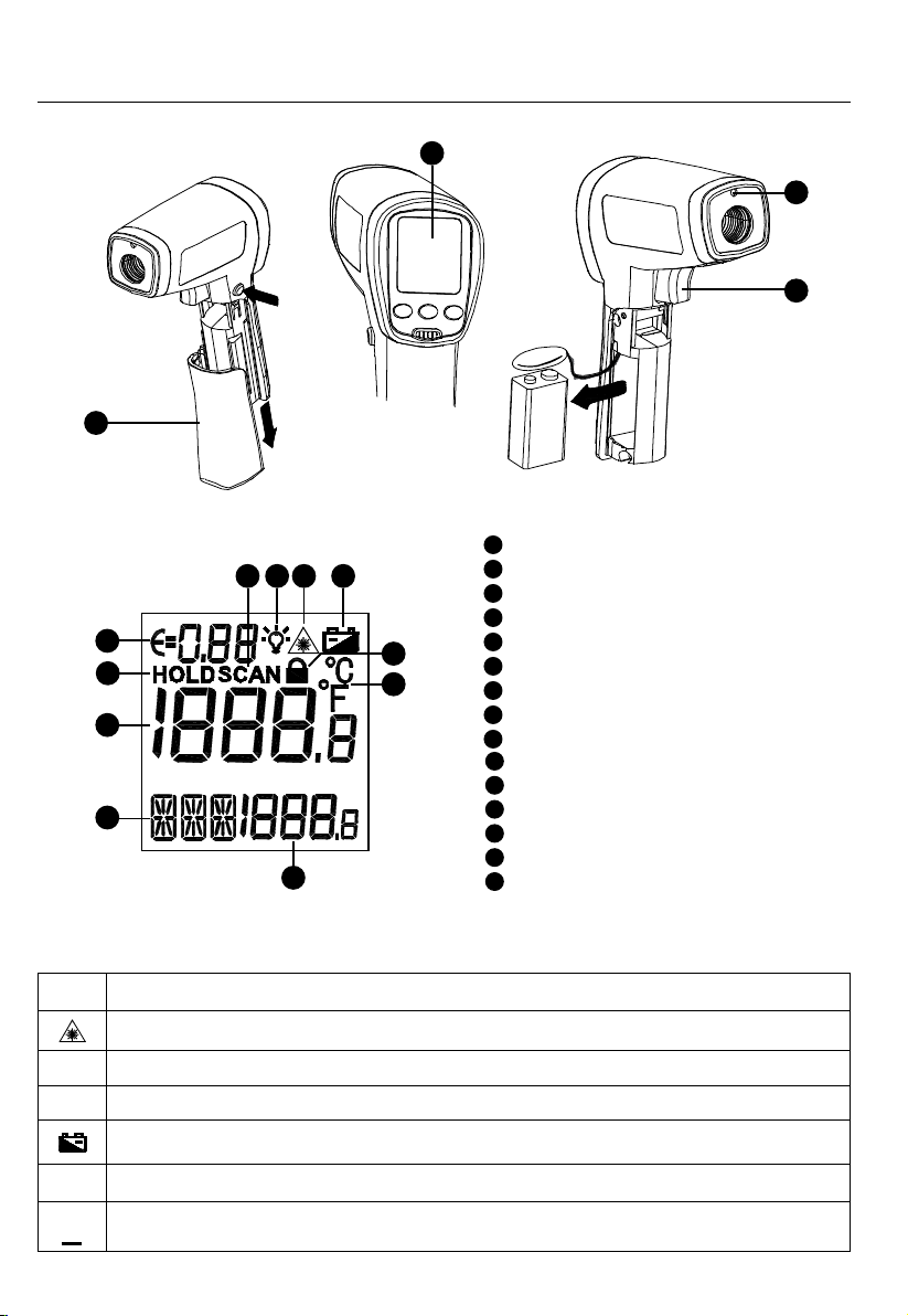
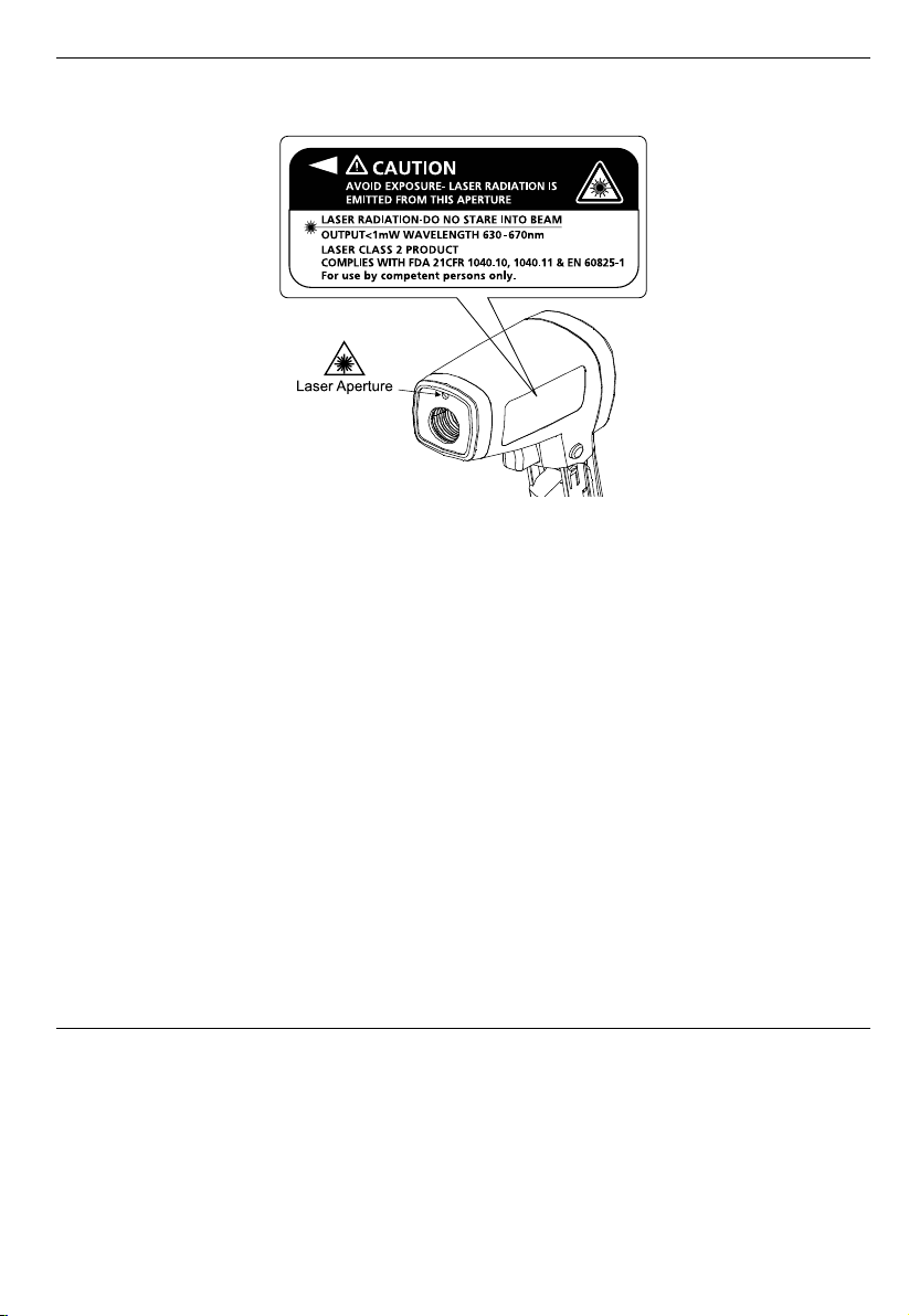
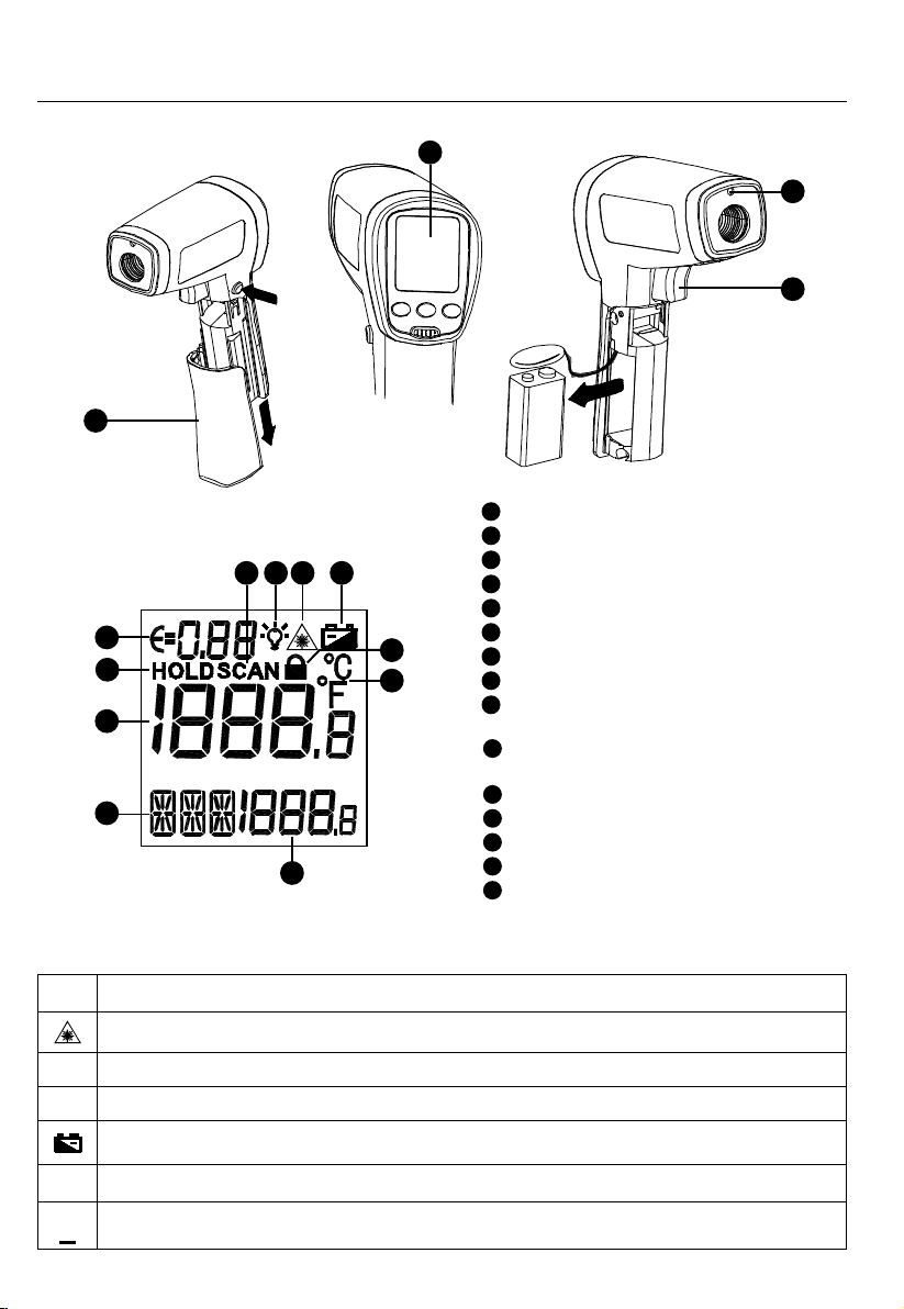
Laser Aperture
1
Trigger
2
Battery Cover
3
Display
4
Laser “ON” symbol
5
Display backlight
6
Measurement lock (Continuous measurement)
7
Temperature unit (Celsius / Fahrenheit)
8
8 seconds auto display hold
9
10
Making measurement (Pulling the trigger)
11
Battery indicator
12
Primary display
13
Secondary display
14
Emissivity (Adjustable from 0.10 to 1.00)
15
MAX, MIN, DIF, AVG temperature values
1
2
SYMBOLS
°C
°F
Caution! Refer to the explanation in this manual.
Warning! Laser light. Do not stare into laser beam.
Celsius.
Fahrenheit.
Battery indication.
Complies with European directives.
Do not dispose of this product as unsorted municipal waste.
Contact a qualified recycler.
2
Page 7
SAFETY INFORMATION
The instrument complies with:
EN 61010-1 General Safety
EN 60825-1 Laser Safety
EN 61326-1 Electromagnetic Emissions and Susceptibility
Warning
• Do not stare into laser beam.
• Do not point laser directly at eye or indirectly off reective surfaces.
• For use by competent persons only.
• Replace the batteries as soon as the low-battery indicator appears.
• Do not use the thermometer if it operates abnormally.
• Do not operate the thermometer around explosive gas, vapor, or dust.
• To avoid a burn hazard or re, know that reective objects may be much hotter than the indicated
temperature reading.
• Do not leave the thermometer on or near objects of high temperature.
• If the thermometer is used in a manner not specied by this manual, the protection provided by the
thermometer may be impaired or may result in hazardous laser radiation exposure.
Cautions
To avoid damaging the thermometer under measurement, protect them from the following:
• EMF (electro-magnetic elds) from arc welders, induction heaters
• Static electricity
• Thermal shock (caused by large or abrupt ambient temperature changes — allow 30 minutes for instrument to
stabilize before use)
• Do not leave the thermometer on or near objects of high temperature
UNPACKING AND INSPECTION
Your shipping carton should include:
1 Thermometer (IR-712 / IR-712-EUR or IR-720 / IR-720-EUR or IR-730 / IR-730-EUR)
1 Carrying case
1 9V battery (installed)
1 Users manual
If any of the items are damaged or missing, return the complete package to the place of purchase for an
exchange.
3
Page 8

FEATURES
The Amprobe IR-712 / IR-712-EUR, a 12:1 distance to spot ratio infrared thermometer, offers best in class
accuracy and response time with a temperature measurement range of 0°F to 1022°F or -18°C to 550°C. The
IR-712 / IR-712-EUR is specifically designed for HVAC/R, electrical, industrial maintenance, automotive as well as
quality control and fire prevention applications.
• 12:1 Distance to Spot ratio
• Temperature range of 0°F to 1022°F or -18°C to 550°C
• Precision accuracy and rapid response time
• Laser pointer, backlit dual LCD Display
• Auto display hold and MAX/MIN memory
• Adjustable emissivity for measuring a variety of materials
The Amprobe IR-720 / IR-720-EUR, a 20:1 distance to spot ratio infrared thermometer, offers best in class
accuracy and response time with a temperature measurement range of -26°F to 1922°F or -32°C to 1050°C. The
IR-720 / IR-720-EUR is specifically designed for HVAC/R, electrical, industrial maintenance, automotive as well as
quality control and fire prevention applications.
• 20:1 Distance to Spot ratio
• Temperature range of -26°F to 1922°F or -32°C to 1050°C
• Precision accuracy and rapid response time
• Laser pointer, backlit dual LCD Display
• Auto display hold and MAX/MIN memory
• Adjustable emissivity for measuring a variety of materials
The Amprobe IR-730 / IR-730-EUR, a 30:1 spot to distance ratio infrared thermometer, offers best in class accuracy
and response time with a temperature measurement range of -26°F to 2282°F or -32°C to 1250°C. The IR-730 /
IR-730-EUR is specifically designed for HVAC/R, electrical, industrial maintenance, automotive as well as quality
control and fire prevention applications.
• 30:1 Distance to Spot ratio
• Temperature range of -26°F to 2282°F or -32°C to 1250°C
• Precision accuracy and rapid response time
• Laser pointer, backlit dual LCD Display
• Auto display hold and MAX/MIN memory
• Adjustable emissivity for measuring a variety of materials
HOW THE THERMOMETERS WORK
Infrared thermometers measure the surface temperature of an object. The thermometer’s optics sense emitted,
reflected, and transmitted energy, which is collected and focused onto a detector. The unit’s electronics translate
the signal into a temperature reading which the unit displays.
OPERATING THE THERMOMETER
Temperature Measurement
The thermometer will turn on when you pull the trigger and also features an auto-off function that
automatically powers down the thermometer after 8 seconds of inactivity.
To measure temperature, point the thermometer at an object and pull the trigger. You can use the laser pointer
to help aim the thermometer. Pull and hold the trigger when measuring the target surface. When the trigger is
released, the display will hold the reading for 8 seconds. Be sure to consider distance-to-spot size ratio and field
of view. The laser is used for aiming only and is not related to temperature measurement.
4
Page 9
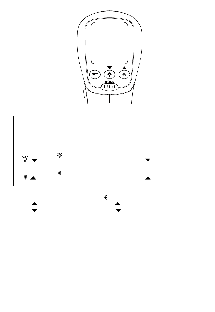
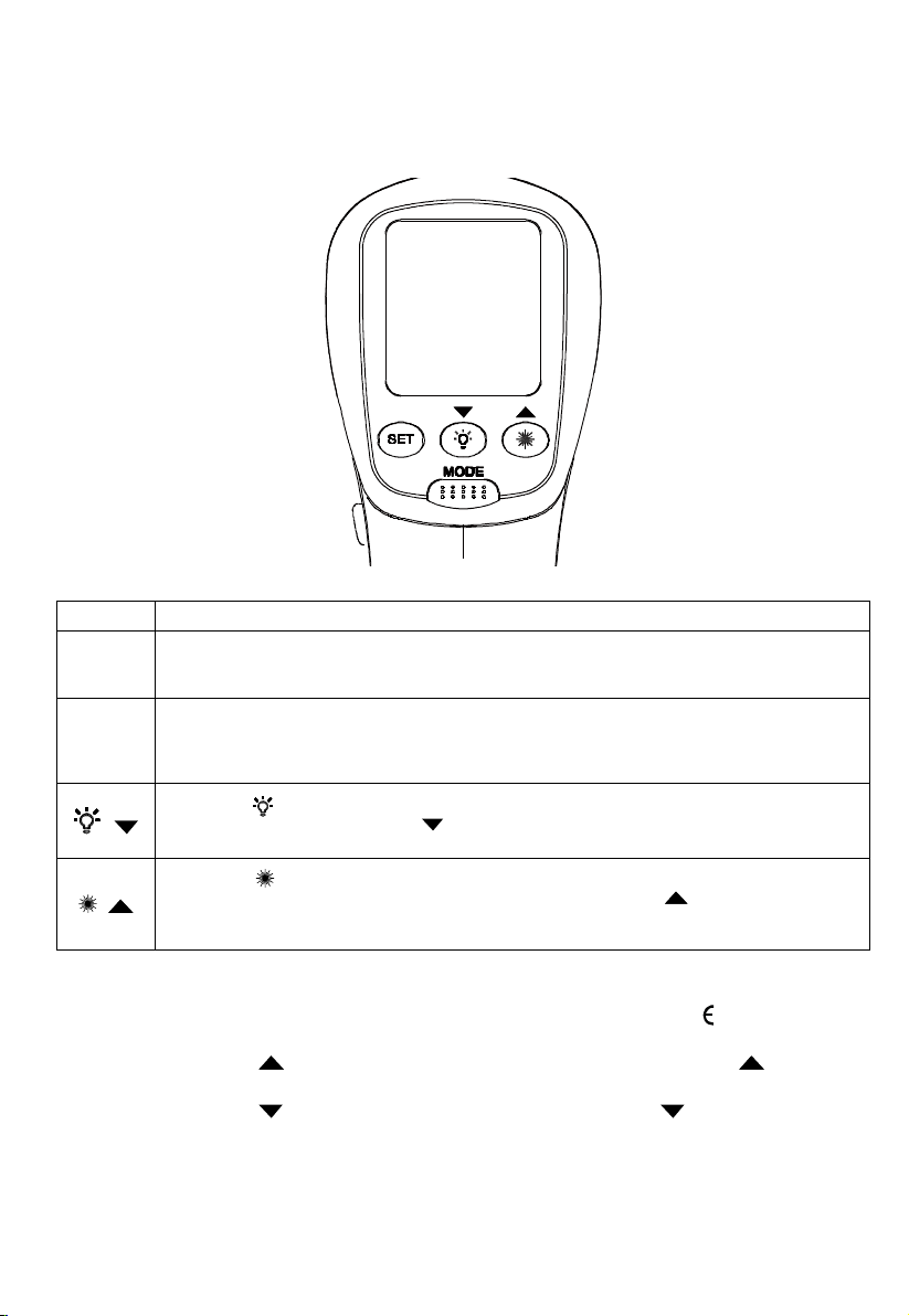
Rotary Switch Positions
Button Description
MODE
SET
/
/
Press MODE button to toggle between MAX, MIN, DIF, and AVG options.
When the thermometer goes into sleep mode, press MODE to turn the thermometer ON
again and it displays the last measurement result.
Press to enter set-up mode stepping through Emissivity, Trigger Lock and Switching °C/°F
set-up. Details refer to the below Emissivity, Trigger Lock and °C / °F set-up.
to turn the display backlight ON or OFF.
Press
When the thermometer enters the setup up mode, press to select a set-up option
(Emissivity, Trigger lock, Switching °C / °F).
Press to turn the laser light ON or OFF.
When the thermometer enters the setup up mode, press
(Emissivity, Trigger lock, Switching °C / °F).
to select a set-up option
Emissivity set-up
1. Press SET button to select Emissivity set-up, icon is blinking on the display
2. Press
3. Press
4. Press MODE button to complete the setting and exit Emissivity set-up, or press SET button to complete the setting
Note: Default emissivity is 0.95.
to increase the value by 0.01. Press and hold for quick setting. The maximum value is 1.00.
to decrease the value by 0.01. Press and hold for quick setting. The minimum value is 0.01.
and continue setting for Trigger Lock.
5
Page 10
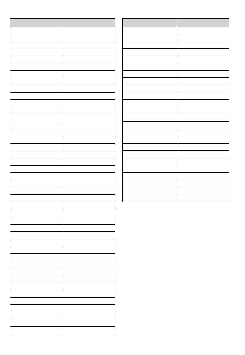
Table of Surface Emissivity
Measure Surface Switch Setting
METALS
Aluminum
Oxidized 0.2 – 0.4
Alloy A3003
Oxidized 0.3
Roughened 0.1 – 0.3
Brass
Burnished 0.3
Oxidized 0.5
Cooper
Oxidized 0.4 – 0.8
Electrical Terminal Blocks 0.6
Haynes
Alloy 0.3 – 0.8
Inconel
Oxidized 0.7 – 0.95
Sandblasted 0.3 – 0.6
Electoropolished 0.15
Iron
Oxidized 0.5 – 0.9
Rusted 0.5 – 0.7
Iron Cast
Oxidized 0.6 – 0.95
Unoxidized 0.2
Molten 0.2 – 0.3
Iron Wrought
Dull 0.9
Lead
Rough 0.4
Oxidized 0.2 – 0.6
Molydbenum
Oxidized 0.2 – 0.6
Nickel
Oxidized 0.2 – 0.5
Platinum
Black 0.9
Steel
Cold-Rolled 0.7 – 0.9
Ground Sheet 0.4 – 0.6
Polished Sheet 0.1
Zinc
Oxidized 0.1
Measure Surface Switch Setting
NON-METALS
Asbestos 0.95
Asphalt 0.95
Basalt 0.7
Carbon
Unoxidized 0.8 – 0.9
Graphite 0.7 – 0.8
Carborundum 0.9
Ceramic 0.95
Clay 0.95
Concrete 0.95
Cloth 0.95
Glass
Plate 0.85
Gravel 0.95
Gypsum 0.8 – 0.95
Ice 0.98
Limestone 0.98
Paper (any colour) 0.95
Plastic
Opaque 0.95
Soil 0.9 – 0.98
Water 0.93
Wood, (natural) 0.9 – 0.95
6
Page 11
Trigger Lock
The thermometer trigger can be locked on for continuous measurement. To lock the trigger:
1. Press SET button to select Trigger Lock set-up, icon
2. Press
3. Press MODE button to complete the setting and exit Trigger Lock set-up, or press SET button to complete the
or to select ON or OFF.
setting and continue setting for °C / °F.
is blinking on the display
°C / °F Set-up
1. Press SET button to select °C / °F set-up, icon °C or °F is blinking on the display
2. Press
3. Press MODE button to complete the setting and exit °C / °F set-up.
or to select °C or °F.
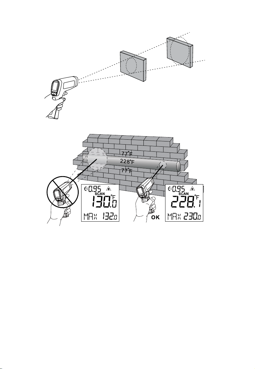
Locating a Hot or Cold Spot
To find a hot or cold spot, aim the thermometer outside the target area. Then, slowly scan across the area with
an up and down motion until you located the hot or cold spot.
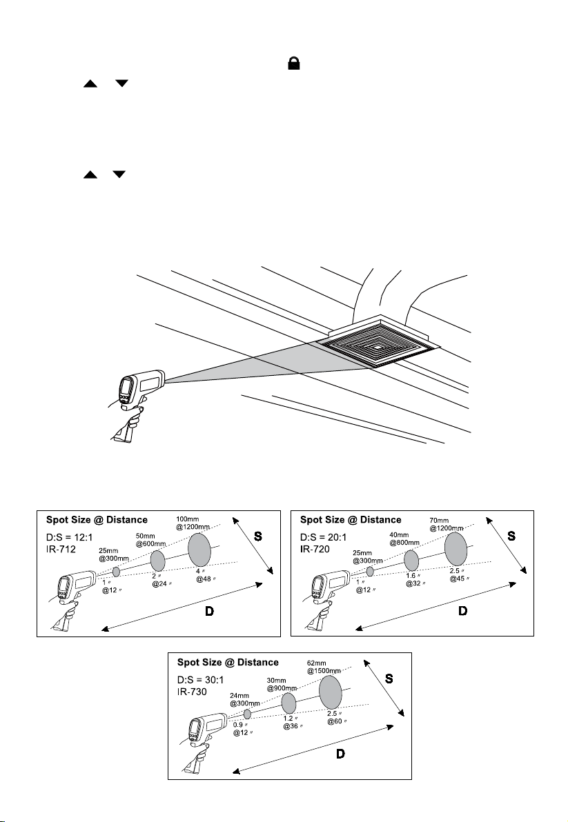
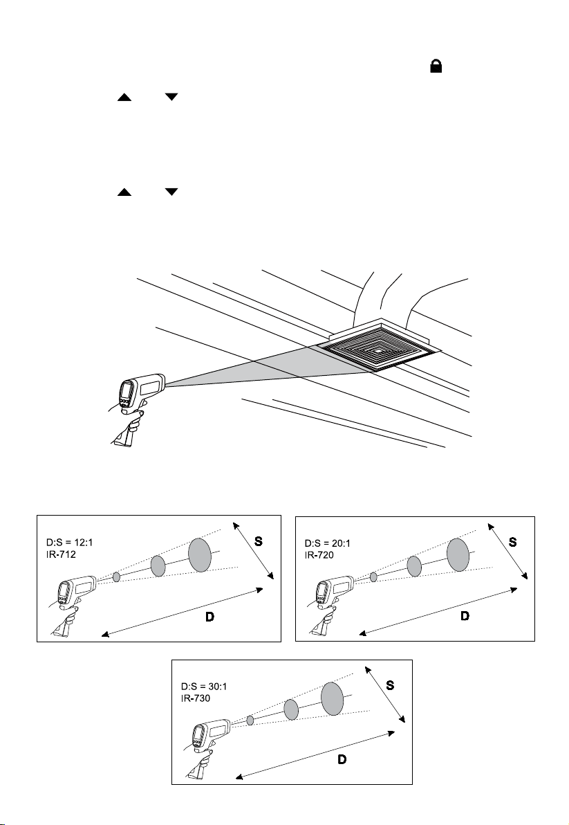
Distance and Spot Size
As the distance (D) from the target being measured increases, the spot size (S) of the area measured by the
instrument becomes larger. The spot size indicates 90% encircled energy.
7
Page 12
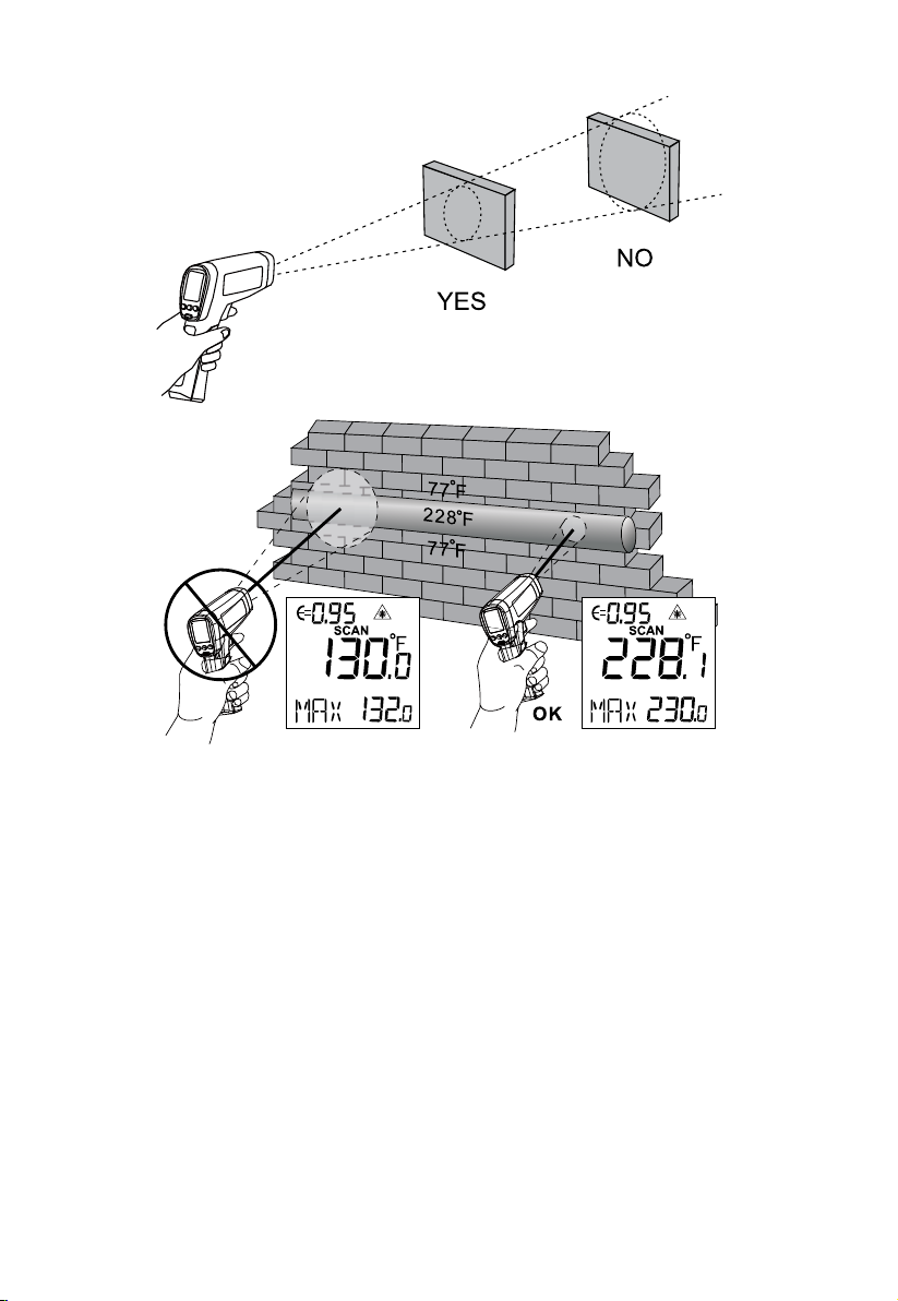
Field of View
Make sure that the target is larger than the spot size. The smaller the target, the closer you should be to it.
Emissivity
Emissivity describes the energy-emitting characteristics of materials. Most organic materials and painted or oxidized
surfaces have an emissivity of about 0.95.
If possible, to compensate for inaccurate readings that may result from measuring shiny metal surfaces, cover
the surface to be measured with masking tape or flat black paint (<150°C / 302°F ) and use the high emissivity
setting. Allow time for the tape or paint to reach the same temperatures as the surface beneath it. Measure the
temperature of the tape or painted surface.
If you cannot use paint or use tape, then you could improve the accuracy of your measurements with the
emissivity selector. Even with emissivity selector, it can be difficult to get a completely accurate infrared
measurement of a target with a shiny or metallic surface.
The thermometer allows you to adjust the emissivity setting for the type of surface before taking measurements.
To determine the adjustment setting please refer to Table of Surface Emissivity.
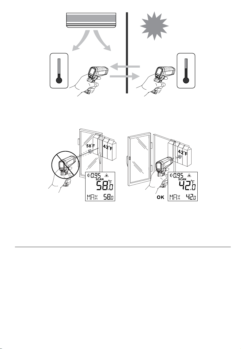
Reminders
1. Changes of surrounding ambient temperature can result in inaccurate readings, allow time for the
instrument to adopt the change of ambient temperatures before use. Specified accuracy applies after 30
minutes when the instrument changes to a different environment ambient temperatures.
8
Page 13

2. The instrument cannot measure through transparent surfaces such as glass. It will measure the surface
temperature of the glass instead.
3. See Table of Surface Emissivity for use in measuring shiny or polished metal surfaces (stainless steel,
aluminum, etc.).
4. Steam, dust, smoke, etc., can prevent accurate measurements by obstructing the instrument’s optics.
TYPICAL MEASUREMENTS
This section describes a variety of measurements often performed by technicians.
Reminder:
• User may select to turn on or off the backlight and laser whenever you are making readings with the
thermometer.
• Relatively high emissivity normally means emissivity setting of about 0.95.
• Relatively low emissivity normally means emissivity setting of about 0.30.
• When user cannot identify the emissivity of the object to be measured, user could cover the surface to be
measured (temperature >150°C) with black electric tape (emissivity of about 0.95). Allow time for the tape
to reach the same temperature as the object to be measured. Measure and record the temperature of the
tape.
Aim the thermometer at the object to be measured, adjust the emissivity setting to make it as the same temperature
as the tape. At this time, the thermometer emissivity setting is close to the emissivity of the object to be measured,
measurement may be taken.
9
Page 14

Testing Contactors (Starters)
1. Press SET to select emissivity. Press / to select relatively low emissivity for bright contacts, or 0.7 mid
level for darkened contacts.
2. Press MODE to select MAX.
3. Measure line and load side of one pole without releasing trigger.
4. A temperature difference between the line and load sides of a pole indicate increased resistance of one
point and a contactor may be failing.
Testing Enclosed Relays
1. Press SET and then press / to set emissivity to relatively low for un-insulated connectors or relatively
high for plastic encased relays or for Bakelite enclosed relays or insulated connectors.
3. Press MODE to select MAX.
4. Start to scan.
5. Measure the relay casing, looking for hot spots.
6. Measure electrical connections on relay terminals looking for hot spots.
Testing Fuses and Buss Connections
1. Press SET and then press / to set emissivity to relatively high for paper covered fuse body or
insulated connections.
2. Press MODE to select MAX.
3. Scan the paper covered length of fuse.
4. Without releasing the trigger, scan each fuse. Unequal temperatures between fuses may indicate voltage or
amperage imbalance.
5. Press SET and then press
buss connections.
6. Press MODE to select MAX.
7. Scan each end cap on each fuse.
Note: Unequal temperatures or a high temperature indicates loose or corroded connection through the fuse
buss spring clip
/ to set emissivity to relatively low, for metal fuses and caps and insulated
Scanning Walls for Air Leaks or Insulation Deficiencies
1. Turn off heating, cooling, and blower.
2. Press SET to select emissivity. Press
window surfaces.
3. Press MODE to select MIN when opposite the side of the wall is at a lower temperature and/or select MAX
when the opposite side of the wall is at a higher temperature.
4. Measure an interior partition wall surface temperature.
5. Do not release the trigger. Record this temperature as your baseline (or benchmark) for a “perfectly”
insulated wall.
6. Face the wall to be scanned. Stand 1.5m away to scan a 6cm spot on the wall (D:S=30:1). Also refer to “Field
of View” section for D:S=12:1 and D:S=20:1 Distance to Spot ratio.
7. Scan horizontal rows of wall from top to bottom, or horizontal rows of ceiling from wall to wall. Look for
greatest deviations from baseline temperature to identify problems. This completes the insulation test scan.
Turn on the blower (no heat, no cooling) and retest. If test results with the blower on are different than results
with the blower off, this may indicate air leaks in conditioned envelope walls. The air leaks are caused by duct
leaks that create a pressure differential across the conditioned space envelope.
/ to select emissivity relatively high for painted surfaces or
10
Page 15

Testing Bearings
Warning - To avoid injury when testing bearings:
1. Do not wear loose clothing, jewelry, or anything around neck when working around moving parts such as
motors, belts, blower, and fans.
2. Make sure an electrical disconnect is within reach and operating correctly and freely.
3. Do not work alone.
Note: It works best to compare two similar motors operating similar loads
1. Press SET and then press
2. Press MODE to select MAX.
3. Enable motor and allow it to reach steady state operating temperatures.
4. Disable the motor if possible.
5. Measure the two motor bearing temperatures.
6. Compare the two motor bearing temperatures. Unequal temperatures or a high temperature can indicate
a lubrication or other bearing problem that is resulting from excess friction.
7. Repeat the sequence for the blower bearings.
/ to select relatively high emissivity.
Testing Belts and Sheaves
1. Press SET and then press / to select relatively high emissivity.
2. Press MODE to select MAX.
3. Enable the motor and allow it to reach a steady state operating temperatures.
4. Aim the thermometer at the surface to be measured.
5. Start recording temperature.
6. Slowly move the thermometer up the belt toward second sheave.
• If belt is slipping, sheave temperature will be high from friction.
• If belt is slipping, belt temperature will remain high between sheaves.
• If belt is not slipping, belt temperature will reduce between sheaves.
• If inner surfaces of sheaves are not a true “V” shape, this indicates belt slippage and will continue to
operate at elevated temperatures until sheave is replaced.
• Sheaves must be properly aligned (include “pitch & yaw”) for belt and sheaves to operate at
appropriate temperatures. A straight edge or taut string, can be used to check alignments.
• Motor sheave should operate at a temperature consistent with blower sheaves.
• If motor sheave is at a higher temperature at motor shaft than at outer circumference, belt is probably
not slipping.
• If outer circumference of sheave is at a higher temperature than sheave at motor shaft, then the belt is probably
slipping and sheaves may be misaligned.
Checking for Blockage in Air-To-Air Evaporator or Condensers
1. Remove panels to gain access to coil return bends or hairpins.
2. Press SET and then press
3. Start the refrigeration system.
4. Aim the thermometer at coil turn bends/hairpins.
5. Start recording temperature.
6. Take temperature of each return bend/hairpin.
• All evaporator return bends/hairpins should be at or slightly above evaporator saturation temperature from the
pressure/temperature chart.
• All condenser return bend/hairpins should be at or slightly less than condenser saturation temperature.
• If a group of return bends/hairpins do not conform to expected temperatures, that indicates a blocked
or restricted distributor or distributor tube.
/ to select relatively high emissivity for copper tube.
11
Page 16
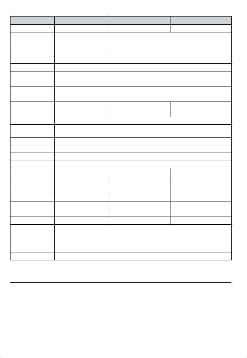
DETAILED SPECIFICATIONS
Feature IR-712 / IR-712-EUR IR-720 / IR-720-EUR IR-730 / IR-730-EUR
Temperature Range -18°C to 550°C (0°F to 1022°F) -32°C to 1050°C (-26°F to 1922°F) -32°C to 1250°C (-26°F to 2282°F)
Accuracy (Assumes
ambient operating
temperature of 21°C to
25°C (70°F to 77°F)
Repeatability ±0.5% of reading or ±0.5°C (±1°F), whichever is greater (Typical)
Display Resolution 0.1°C / 0.1°F
Spectral Response 8µm to14µm
Laser Sighting Single point laser
Laser Power Output > 1mW Class 2, wavelength 630 to 670nm
Response Time (95%) 250ms
Distance to Spot (D:S) 12:1 20:1 30:1
Minimum Spot Size 25mm 25mm 24mm
Emissivity Digitally adjustable from 0.10 to 1.00 by 0.01. Pre-set emissivity is 0.95
Ambient Operating
Temperature
Relative Humidity 0% to 75% non-condensing
Storage Temperature -20°C to 65°C / -4°F to 150°F (Battery not installed)
Temperature Display °C or °F selectable
Display Hold 8 seconds
MAX/MIN Temperature
Display
DIF/AVG Temperature
Display
Dual LCD Display √ √ √
LCD Backlit √ √ √
Low Battery Indication √ √ √
Tripod mount √ √ √
Power 9V 6F22 alkaline battery or equivalent
Battery Life 10 hours with laser and backlight on
Dimension (H x L x W) Approximately 169 x 138 x 53 mm (6.7 x 5.4 x 2.1 in)
Weight Approximately 290 g (0.64 lb) with battery installed
±1.8% or ±1.8°C (±4F),
whichever is greater (Typical)
0°C to 50°C / 32°F to 120°F
√ √ √
√ √ √
30 hours with laser and backlight off
>0°C to 1250°C (>32°F to 2282°F): ±1.8% or ±1.8°C (±4F), whichever is
greater (Typical)
-32°C to 0°C (-26°F to 32°F): ±1.8%+1°C (2°F) or ±2.8°C (±6F),
whichever is greater (Typical)
MAINTENANCE
Lens Cleaning: Blow off loose particles using clean compressed air. Gently brush remaining debris away with a camel
hair brush. Carefully wipe the surface with a moist cotton swab. The swab may be moistened with water or rubbing
alcohol.
NOTE: DO NOT use solvents to clean the plastic lens.
Case Cleaning: Use soap and water on a damp sponge or soft cloth.
12
Page 17

Caution!
Do not submerge the unit in water.
TROUBLE SHOOTING
Code Problem Action
OL Target temperature is over range Select target within specifications
-OL Target temperature is under range Select target within specifications
Low battery Check and/or replace battery
Battery indication
Blank display Possible dead battery Check and/or replace battery
Laser does not work
1. Low or dead battery
2. Ambient temperature above 40°C (104°F)
1. Replace battery
2. Use in area with lower ambient
temperature
BATTERY REPLACEMENT
To install or change one 9V battery (see below):
1. Push the button and pull the handle downward to open battery cover.
2. Install the battery noting its correct polarity.
3. Re-install the battery cover.
Battery: 9V 6F22 alkaline battery or equivalent
13
Page 18

Page 19

IR-712
IR-712-EUR
Thermomètre IR 12:1
IR-720
IR-720-EUR
Thermomètre IR 20:1
IR-730
IR-730-EUR
Thermomètre IR 30:1
Mode d’emploi
Français
11/2013, 4279845 B
©2013 Amprobe Test Tools.
Tous droits réservés. Imprimé en Chine.
Page 20

Limites de garantie et de responsabilité
Amprobe garantit l’absence de vices de matériaux et de fabrication de ce produit pendant une période d’un an
prenant effet à la date d’achat, sauf disposition contraire prévue par la loi. Cette garantie ne s’applique pas aux
fusibles, aux piles jetables ni à tout produit mal utilisé, modié, contaminé, négligé ou endommagé par accident
ou soumis à des conditions anormales d’utilisation et de manipulation. Les revendeurs n’ont pas l’autorisation
de prolonger toute autre garantie au nom d’Amprobe. Pour bénéficier de la garantie, renvoyez le produit
accompagné d’un justicatif d’achat auprès d’un centre de services agréé par Amprobe ou d’un distributeur ou
d’un revendeur Amprobe. Voir la section Réparation pour tous les détails. LA PRÉSENTE GARANTIE EST LE SEUL
ET EXCLUSIF RECOURS DE L’UTILISATEUR TOUTES AUTRES GARANTIES, EXPLICITES, IMPLICITES OU STATUTAIRES,
NOTAMMENT LE CAS ÉCHÉANT LES GARANTIES DE QUALITÉ MARCHANDE OU D’ADAPTATION À UN OBJECTIF
PARTICULIER SONT EXCLUES PAR LES PRÉSENTES. LE FABRICANT NE SERA EN AUCUN CAS TENU RESPONSABLE
DE DOMMAGES PARTICULIERS, INDIRECTS, ACCIDENTELS OU CONSÉCUTIFS, NI D’AUCUNS DÉGATS OU PERTES
DE DONNÉES, SUR UNE BASE CONTRACTUELLE, EXTRA-CONTRACTUELLE OU AUTRE. Étant donné que certaines
juridictions n’admettent pas les limitations d’une condition de garantie implicite ou l’exclusion ou la limitation
de dégâts accidentels ou consécutifs, il se peut que les limitations et les exclusions de cette garantie ne
s’appliquent pas à votre cas.
Réparation
Tous les outils de test renvoyés pour être réparés au titre de la garantie ou pour étalonnage doivent être
accompagnés des éléments suivants : nom, raison sociale, adresse, numéro de téléphone et justicatif d’achat.
Ajoutez également une brève description du problème ou du service demandé et incluez les cordons de test avec
l’appareil. Les frais de remplacement ou de réparation hors garantie doivent être acquittés par chèque, mandat,
carte de crédit avec date d’expiration, ou par bon de commande payable à l’ordre de Amprobe.
Remplacements et réparations sous garantie – Tous pays
Veuillez lire la déclaration de garantie et vérifiez la pile avant de demander une réparation. Pendant la période
de garantie, tout outil de test défectueux peut être renvoyé auprès de votre distributeur Amprobe® pour
être échangé contre un produit identique ou similaire. Consultez la section « Where to Buy » sur le site www.
Amprobe.com pour obtenir la liste des distributeurs dans votre région. Les appareils sous garantie devant être
remplacés ou réparés au Canada et aux États-Unis peuvent également être envoyés dans un centre de services
Amprobe® (voir les adresses ci-dessous).
Remplacements et réparations hors garantie – Canada et États-Unis
Les appareils à réparer hors garantie au Canada et aux États-Unis doivent être envoyés dans un centre de
services Amprobe. Appelez Amprobe® ou renseignez-vous auprès de votre lieu d’achat pour connaître les tarifs
en vigueur de remplacement ou de réparation.
Aux États-Unis et au Canada
Amprobe Amprobe
Everett, WA 98203 Mississauga, ON L4Z 1X9Canada
Tél. : 877-AMPROBE (267-7623) Tél. : 905-890-7600
Remplacements et réparations hors garantie – Europe
Les appareils européens non couverts par la garantie peuvent être remplacés par votre distributeur Amprobe®
pour une somme nominale. Consultez la section « Where to Buy » sur le site www.Amprobe.com pour obtenir la
liste des distributeurs dans votre région.
Adresse postale européenne*
Amprobe® Europe
Beha-Amprobe GmbH
In den Engematten 14
79286 Glottertal, Allemagne
Tél. : +49 (0) 7684 8009 - 0
www.amprobe.eu
*(Réservée à la correspondance – Aucun remplacement ou réparation n’est possible à cette adresse. Nos clients
européens doivent contacter leur distributeur.)
Page 21

IR-712 / IR-712-EUR Thermomètre IR 12:1
IR-720 / IR-720-EUR Thermomètre IR 20:1
IR-730 / IR-730-EUR Thermomètre IR 30:1
TABLE DES MATIÈRES
SYMBOLES .................................................................................................................................................................... 2
CONSIGNES DE SÉCURITÉ ............................................................................................................................................ 3
DÉBALLAGE ET INSPECTION ........................................................................................................................................ 3
FONCTIONNALITÉS ....................................................................................................................................................... 4
FONCTIONNEMENT DES THERMOMÈTRES ................................................................................................................. 4
UTILISATION DU THERMOMÈTRE ................................................................................................................................4
Mesures de température ........................................................................................................................................ 4
Localisation d'un point chaud ou froid .................................................................................................................. 7
Distance et taille du point focal (spot) ................................................................................................................... 7
Champ de visée ........................................................................................................................................................ 8
Émissivité .................................................................................................................................................................. 8
Rappels ..................................................................................................................................................................... 8
MESURES TYPIQUES ..................................................................................................................................................... 9
CARACTÉRISTIQUES ..................................................................................................................................................... 12
ENTRETIEN .................................................................................................................................................................... 12
DÉPANNAGE .................................................................................................................................................................13
CHANGEMENT DES PILES ............................................................................................................................................. 13
1
Page 22
IR-712 / IR-712-EUR Thermomètre IR 12:1
IR-720 / IR-720-EUR Thermomètre IR 20:1
IR-730 / IR-730-EUR Thermomètre IR 30:1
3
1110
56
14
9
7
8
12
15
13
4
1
2
Ouverture laser
1
Gâchette
2
Couvercle de pile
3
Affichage
4
Symbole laser « actif »
5
Affichage du rétroéclairage
6
Verrouillage de mesure (mesure continue)
7
Unité de température (Celsius / Fahrenheit)
8
Maintien d'affichage automatique de
9
8 secondes
10
Établissement des mesures
(en actionnant la gâchette)
11
Témoin de pile
12
Fenêtre principale
13
Fenêtre secondaire
14
Émissivité (réglable de 0,10 à 1,00)
15
Valeurs de température MAX, MIN, DIF, AVG
SYMBOLES
Attention ! Se reporter aux explications de ce manuel.
Avertissement ! Lumière laser. Ne pas regarder dans le faisceau laser.
Celsius.
°C
Fahrenheit.
°F
Témoin de pile.
Conforme aux directives européennes.
Ne pas mettre ce produit au rebut parmi les déchets ménagers.
Consulter un centre de recyclage homologué.
2
Page 23

CONSIGNES DE SÉCURITÉ
L'instrument est conforme aux normes suivantes :
Sécurité générale EN 61010-1
Sécurité laser EN 60825-1
Susceptibilité et émissions électromagnétiques EN 61326-1
Ouverture laser
Avertissement
• Ne pas regarder dans le faisceau laser.
• Ne pas pointer directement le laser en direction des yeux, ou indirectement vers des surfaces
rééchissantes.
• Utilisation réservée aux personnes compétentes.
• Remplacer les piles dès que l’indicateur des piles déchargées apparaît.
• Ne pas utiliser le thermomètre s’il ne fonctionne pas normalement.
• Ne pas utiliser le thermomètre à proximité de gaz explosifs, de vapeurs ou de poussière.
• Pour éviter les risques d’incendie ou de brûlures, ne pas oublier que les objets rééchissants sont souvent
plus chauds que la température indiquée sur le thermomètre.
• Ne pas laisser le thermomètre sur ou à proximité d'objets à température élevée.
• Utiliser le thermomètre en respectant les indications de ce mode d’emploi an de ne pas entraver la
protection intégrée au thermomètre et de pas provoquer d'exposition dangereuse au rayonnement
laser.
Attention
Pour ne pas endommager le thermomètre pendant la mesure, le protéger des éléments suivants :
• CEM (champs électromagnétiques) des soudeurs à l'arc, chauffages à induction
• Électricité statique
• Chocs thermiques (provoqués par des changements de température ambiante importants ou abrupts : laisser
l'appareil se stabiliser 30 minutes avant l'emploi)
• Ne pas laisser le thermomètre sur ou à proximité d'objets à température élevée
DÉBALLAGE ET INSPECTION
Le carton d’emballage doit inclure les éléments suivants :
1 thermomètre (IR-712 / IR-712-EUR ou IR-720 / IR-720-EUR ou IR-730 / IR-730-EUR)
1 sacoche de transport
1 pile de 9 V (installée)
1 Mode d’emploi
Si l’un de ces éléments est endommagé ou manquant, renvoyez le contenu complet de l’emballage au lieu
d’achat pour l’échanger.
3
Page 24

FONCTIONNALITÉS
Le thermomètre Amprobe IR-712 / IR-712-EUR, un thermomètre infrarouge avec un rapport de distance à
taille de point focal de 12:1, offre la meilleure précision de sa classe et un temps de réponse avec une plage de
mesure de températures de -18 °C à 550 °C (0 °F à 1022 °F). L'IR-712 / IR-712-EUR est spécialement conçu pour les
applications CVC/R, l'électricité, la maintenance industrielle, l'automobile ainsi que le contrôle de la qualité et la
prévention des incendies.
• Rapport de distance à taille de point focal 12:1
• Plage de températures de -18 °C à 550 °C (0 °F à 1022 °F)
• Précision des mesures et temps de réponse rapide
• Pointeur laser, double afchage LCD rétroéclairé
• Maintien automatique de l'afchage et mémoire MAX/MIN
• Émissivité réglable pour la mesure de divers matériaux
Le thermomètre Amprobe IR-720 / IR-720-EUR, un thermomètre infrarouge avec un rapport de distance à taille
de point de 20:1, offre la meilleure précision de sa classe et un temps de réponse avec une plage de mesure
de températures de -32 °C à 1050 °C (-26 °F à 1922 °F). L'IR-720 / IR-720-EUR est spécialement conçu pour les
applications CVC/R, l'électricité, la maintenance industrielle, l'automobile ainsi que le contrôle de la qualité et la
prévention des incendies.
• Rapport de distance à taille de point focal 20:1
• Plage de températures de -32 °C à 1050 °C (-26 °F à 1922 °F)
• Précision des mesures et temps de réponse rapide
• Pointeur laser, double afchage LCD rétroéclairé
• Maintien automatique de l'afchage et mémoire MAX/MIN
• Émissivité réglable pour la mesure de divers matériaux
Le thermomètre Amprobe IR-730 / IR-730-EUR, un thermomètre infrarouge avec un rapport de distance à taille
de point focal de 30:1, offre la meilleure précision de sa classe et un temps de réponse avec une plage de mesure
de températures de -32 °C à 1250 °C (-26 °F à 2282 °F). L'IR-730 / IR-730-EUR est spécialement conçu pour les
applications CVC/R, l'électricité, la maintenance industrielle, l'automobile ainsi que le contrôle de la qualité et la
prévention des incendies.
• Rapport de distance à taille de point focal 30:1
• Plage de températures de -32 °C à 1250 °C (-26 °F à 2282 °F)
• Précision des mesures et temps de réponse rapide
• Pointeur laser, double afchage LCD rétroéclairé
• Maintien automatique de l'afchage et mémoire MAX/MIN
• Émissivité réglable pour la mesure de divers matériaux
FONCTIONNEMENT DES THERMOMÈTRES
Les thermomètres infrarouges mesurent la température de surface d'un objet. L'optique du thermomètre
détecte l'énergie émise, réfléchie et transmise qui est collectée et focalisée sur un détecteur. L'électronique de
l'appareil convertit le signal dans la lecture de température qui apparaît sur l'afcheur.
UTILISATION DU THERMOMÈTRE
Mesures de température
Le thermomètre se met sous tension lorsque vous appuyez sur la gâchette
Le thermomètre se met hors tension lorsqu'aucune activité n'est détectée pendant 8 secondes.
Pour mesurer la température, pointez le thermomètre sur un objet et actionnez la gâchette. Vous pouvez utiliser
le pointeur laser pour mieux viser avec le thermomètre. Actionnez et maintenez la gâchette pour mesurer la
4
Page 25
surface ciblée. Quand vous relâchez la gâchette, l'écran maintient l'affichage de la mesure pendant 8 secondes.
Veillez à respecter la distance par rapport à la taille du point focal et le champ de visée. Le laser n'est utilisé que
pour viser et n'a pas d'incidence sur la mesure de température.
Le thermomètre possède une fonction d'arrêt automatique qui met le thermomètre automatiquement hors
tension après 8 secondes d'inactivité. Actionnez la gâchette pour mettre le thermomètre sous tension.
Positions du sélecteur rotatif
Bouton Description
MODE
SET
Appuyer sur le bouton MODE pour basculer entre les options MAX, MIN, DIF et AVG.
Quand le thermomètre passe en mode de veille, appuyer sur MODE pour remettre le
thermomètre de nouveau sous tension pour qu'il afche la dernière mesure obtenue.
Appuyer sur cette touche pour passer en mode de configuration, soit alternativement pour
définir l'émissivité, verrouiller le déclenchement des mesures et sélectionner °C / °F.
Les détails ci-dessous renvoient à la configuration de l'émissivité, au verrouillage du
déclenchement des mesures et à la sélection °C / °F.
Appuyer sur
mode de configuration, appuyer sur
/
verrouillage du déclenchement des mesures et sélection °C / °F).
Appuyer sur pour activer ou désactiver le laser.
/
Quand le thermomètre passe en mode de conguration, appuyer sur
option de configuration (émissivité, verrouillage du déclenchement des mesures et sélection °C
/ °F).
pour activer ou désactiver le rétroéclairage.Quand le thermomètre passe en
pour sélectionner une option de configuration (émissivité,
pour sélectionner une
Configuration de l'émissivité
1. Appuyez sur le bouton SET pour sélectionner la configuration de l'émissivité, l'icône clignote sur
l'affichage.
2. Appuyez sur la touche
un réglage rapide. La valeur maximale est 1,00.
3. Appuyez sur la touche
rapide. La valeur par défaut est 0,01.
4. Appuyez sur le bouton MODE pour compléter le réglage et quitter la configuration de l'émissivité, ou sur le bouton
SET pour compléter le réglage et procéder au verrouillage du déclenchement des mesures.
Remarque : L'émissivité par défaut est 0,95.
pour augmenter la valeur affichée par pas de 0,01. Maintenez enfoncé pour
pour diminuer la valeur par pas de 0,01. Maintenez enfoncé pour un réglage
5
Page 26
Tableau d’émissivité des surfaces
Surface de mesure Réglage du sélecteur
MÉTAUX
Aluminium
Oxydé 0,2 à 0,4
Alliage A3003
Oxydé 0,3
Rugosifié 0,1 à 0,3
Laiton
Lustré 0,3
Oxydé 0,5
Cuivre
Oxydé 0,4 à 0,8
Bornier électrique 0.6
Haynes
Alliage 0,3 à 0,8
Inconel
Oxydé 0,7 à 0,95
Sablé 0,3 à 0,6
Électropoli 0,15
Fer
Oxydé 0,5 à 0,9
Rouillé 0,5 à 0,7
Fonte
Oxydé 0,6 à 0,95
Inoxydé 0,2
Fondu 0,2 à 0,3
Fer forgé
Terne 0,9
Plomb
Rugueux 0,4
Oxydé
Molybdène
Oxydé 0,2 à 0,6
Nickel
Oxydé 0,2 à 0,5
Platine
Noir 0,9
Acier
Laminé à froid 0,7 à 0,9
Meulé 0,4 à 0,6
Poli 0,1
Zinc
Oxydé 0,1
0,2 à 0,6
Surface de mesure Réglage du sélecteur
NON MÉTAUX
Amiante 0,95
Asphalte 0,95
Basalte 0,7
Carbone
Inoxydé 0,8 à 0,9
Graphite 0,7 à 0,8
Carborundum 0,9
Céramique 0,95
Argile 0,95
Béton 0,95
Tissu 0,95
Verre
Tôle 0,85
Gravier 0,95
Gypse 0,8 à 0,95
Glace 0,98
Calcaire 0,98
Papier (toutes couleurs) 0,95
Plastique
Opaque 0,95
Sols 0,9 à 0,98
Eau 0,93
Bois, (naturel) 0,9 à 0,95
6
Page 27
Verrouillage du déclenchement des mesures
Le déclenchement du thermomètre peut être verrouillé pour obtenir une mesure continue. Pour verrouiller le
déclenchement :
1. Appuyez sur le bouton SET pour verrouiller le déclenchement des mesures, l'icône
clignote sur
l'affichage.
2. Appuyez sur
ou sur pour activer ou désactiver l'option.
3. Appuyez sur le bouton MODE pour compléter le réglage et quitter le verrouillage du déclenchement des
mesures, ou sur le bouton SET pour compléter le réglage et passer à la sélection des degrés °C / °F.
Configuration °C / °F
1. Appuyez sur le bouton SET pour sélectionner la configuration des degrés °C / °F, l'icône °C ou °F clignote sur
l'affichage.
2. Appuyez sur
ou sur pour sélectionner °C ou °F.
3. Appuyez sur le bouton MODE pour compléter le réglage et quitter la configuration des degrés °C / °F.
Localisation d'un point chaud ou froid
Pour identier un point chaud ou froid, pointez le thermomètre en dehors de la zone ciblée. Balayez ensuite
lentement la zone d'un mouvement de bas en haut jusqu'à ce que le point chaud ou froid soit localisé.
Distance et taille du point focal (spot)
À mesure que la distance (D) de la cible mesurée augmente, la taille du point focal (S) de la zone mesurée par
l'instrument grandit. La taille du point focal indique 90 % d'énergie circonscrite.
Rapport de distance à spot
50 mm
1 à 12 po.
à 600 mm
2 à 24 po.
25 mm
à 300 mm
100 mm
à 1200 mm
4 à 48 po.
Rapport de distance à spot
24 mm
à 300 mm
0,9 à 12 po.
Rapport de distance à spot
25 mm
à 300 mm
1 à 12 po.
62 mm
à 1500 mm
30 mm
à 900 mm
1,2 à 36 po.
2,5 à 60 po.
7
40 mm
à 800 mm
1,6 à 32 po.
70 mm
à 1200 mm
2,5 à 45 po.
Page 28
Champ de visée
Vérifiez que la cible est plus grande que la taille du point focal. Plus la cible est petite, plus il faut s'en
rapprocher.
NON
OUI
Émissivité
L'émissivité décrit les caractéristiques d'émission d'énergie des matériaux. La plupart des matériaux organiques et
des surfaces peintes ou oxydées ont une émissivité de 0,95. Le cas échéant, pour compenser les lectures inexactes
susceptibles de résulter des mesures de surfaces métalliques brillantes, couvrez la surface à mesurer de ruban
opaque ou de peinture matte noire (< 150 °C / 302 °F) et utiliser le paramètre de haute émissivité. Laissez
au ruban ou à la peinture le temps d'atteindre les mêmes températures que la surface sous-jacente. Mesurez la
température du ruban ou de la surface peinte.
Si vous ne pouvez pas utiliser de peinture ou de ruban, vous pouvez améliorer la précision de vos mesures avec le
sélecteur d'émissivité. Même avec le sélecteur d'émissivité, il est parfois difficile d'obtenir une lecture infrarouge
absolument précise d'une cible présentant une surface brillante ou métallique.
Le thermomètre permet d'ajuster l'émissivité selon le type de surface mesuré.
Reportez-vous au tableau d'émissivité des surfaces Mais il ne s'agit que d'un cas typique. Vous pouvez utiliser vos
propres données et utiliser d'autres définitions pour vos matériaux.
Rappels
1. Les changements de la température ambiante environnante peuvent entraîner des mesures inexactes,
laissez l'instrument s'adapter au changement de température ambiant avant de l'utiliser. La précision
spéciée s'applique après 30 minutes lorsque l'instrument passe dans un milieu ambiant différent.
8
Page 29
25 °C/77 °F
35 °C/95 °F
Attendre 30 minutes
2. L'instrument ne peut pas établir de mesures à travers des surfaces transparentes telles que le verre. Dans ce
cas, il mesure en fait la température de surface du verre.
3. Reportez-vous au tableau d'émissivité des surfaces pour mesurer les surfaces métalliques brillantes ou polies
(acier inoxydable, aluminium, etc.).
4. La vapeur, la poussière, la fumée, etc., peuvent perturber la précision des mesures en obstruant l'optique
de l'instrument.
MESURES TYPIQUES
Cette section décrit une variété de mesures souvent effectuées par les techniciens.
Rappel :
• L'utilisateur peut décider de mettre sous tension ou hors tension le rétroéclairage et le laser en effectuant
des mesures avec le thermomètre.
• Une émissivité relativement élevée renvoie normalement à une émissivité d'environ 0,95.
• Une émissivité relativement faible renvoie normalement à une émissivité d'environ 0,30.
• Lorsque l'utilisateur ne peut pas identier l'émissivité de l'objet à mesurer, il peut couvrir la surface à
mesurer (température >150 °C) avec du ruban d'électricien noir (émissivité d'environ 0,95). Laissez le temps
au ruban d'atteindre la même température que l'objet à mesurer. Mesurez et enregistrez la température
du ruban.
Pointez le thermomètre vers l'objet à mesurer, ajustez le paramètre d'émissivité pour l'aligner sur la même
température que le ruban. À ce stade, le paramètre d'émissivité du thermomètre est proche de l'émissivité de l'objet
à mesurer ; la mesure peut démarrer.
9
Page 30

Tests des contacteurs (démarreurs)
1. Appuyez sur SET pour sélectionner l'émissivité. Appuyez sur / pour sélectionner une émissivité
relativement faible pour les contacts brillants, ou un niveau intermédiaire de 0,7 pour les contacts sombres.
2. Appuyez sur MODE pour sélectionner MAX.
3. Mesurez la ligne et le côté charge d'un pôle sans relâcher la gâchette.
4. Une différence de température entre la ligne et le côté charge d'un pôle indique une résistance accrue d'un
point et la défaillance probable d'un contacteur.
Test de relais sous coffret
1. Appuyez sur SET, puis sur / pour définir une émissivité relativement faible pour les connecteurs non
isolés, ou relativement haute pour les relais sous coffret en plastique ou en bakélite ou les connecteurs
isolés.
2. Appuyez sur MODE pour sélectionner MAX.
3. Lancez l'analyse.
4. Mesurez le boîtier du relais, en recherchant les points chauds.
5. Mesurez les connexions électriques aux bornes du relais en recherchant les points chauds.
Test des raccordements à fusibles et à barres omnibus
1. Appuyez sur SET puis sur / pour définir une émissivité relativement élevée pour un corps de fusible à
revêtement papier ou des connexions isolées.
2. Appuyez sur MODE pour sélectionner MAX.
3. Balayez la partie recouverte de papier du fusible.
4. Balayez chaque fusible sans relâcher la gâchette. Des températures inégales entre les fusibles sont
susceptibles d'indiquer un déséquilibre d'intensité ou de tension.
5. Appuyez sur SET puis sur
fusibles métalliques et les connexions de barres omnibus non isolées.
6. Appuyez sur MODE pour sélectionner MAX.
7. Balayez chaque capuchon d'extrémité de chaque fusible.
Remarque : Des températures inégales ou une température élevée indiquent une connexion desserrée ou
corrodée dans la pince à ressort de la barre omnibus à fusibles.
/ pour définir une émissivité relativement faible pour les capuchons et les
Examen des murs pour détecter les fuites d'air ou les défauts d'isolation
1. Mettez le chauffage, le refroidissement et la ventilation hors tension.
2. Appuyez sur SET pour sélectionner l'émissivité. Appuyez sur
relativement élevée pour des surfaces peintes ou les surfaces de fenêtres.
3. Appuyez sur MODE pour sélectionner MIN quand la paroi opposée du murs est de température inférieure
et/ou sélectionner MAX quand la paroi opposée du mur est de température supérieure.
4. Mesurez une température de surface murale de partition intérieure.
5. Ne relâchez pas la gâchette. Enregistrez cette température de référence (point zéro) pour un mur
« parfaitement » isolé.
6. Faites face au mur à examiner. Tenez-vous à 1,5 m pour balayer un spot de 6 cm sur le mur (D:S=30:1).
Reportez-vous également à la section « Champ de visée » pour un rapport de distance à taille de point
focal (spot) D:S=12:1 et D:S=20:1.
7. Balayez des bandes horizontales de mur de haut en bas, ou des rangées horizontales de plafond d'un mur
à l'autre. Recherchez les plus grands écarts par rapport à la température de référence pour identifier les
problèmes. Cela conclut le test d'isolation.
Mettez le ventilateur en route (sans chaleur ni refroidissement) et répétez le test. Si les résultats du test avec le
ventilateur activé sont différents des résultats avec le ventilateur éteint, cela signale probablement des fuites
d'air dans l'enveloppe d'isolation des murs. Les fuites d'air sont liées à des fuites dans les conduits qui créent un
différentiel de pression dans l'enveloppe de l'espace climatisé.
10
/ pour sélectionner une émissivité
Page 31

Test de paliers de roulement
Avertissement
Pour éviter les blessures en testant les paliers :
1. L’utilisateur ne doit pas porter de vêtements lâches, de bijoux ou tout autre élément autour du cou en
travaillant à proximité de pièces mobiles telles que les moteurs, courroies et ventilateurs.
2. Vérifier qu'un interrupteur électrique est à portée de la main et qu'il fonctionne correctement et
librement.
3. Ne pas travailler seul.
Remarque : Il vaut mieux comparer deux moteurs similaires utilisant des charges similaires.
1. Appuyez sur SET puis sur
2. Appuyez sur MODE pour sélectionner MAX.
3. Actionnez le moteur et laissez-le atteindre les températures de régime permanent.
4. Coupez le moteur si possible.
5. Mesurez les deux températures des paliers moteur.
6. Comparez les deux températures des paliers moteur. Des températures inégales ou une température élevée
peuvent indiquer une anomalie de lubrification ou autre du palier résultant d'une friction excessive.
7. Répétez la séquence pour les paliers du ventilateur.
Test des courroies et des poulies
1. Appuyez sur SET puis sur / pour sélectionner une émissivité relativement élevée.
2. Appuyez sur MODE pour sélectionner MAX.
3. Actionnez le moteur et laissez-le atteindre les températures de régime permanent.
4. Pointez le thermomètre vers la surface à mesurer.
5. Lancez l'enregistrement de la température.
6. Déplacez lentement le thermomètre vers le haut de la courroie et la deuxième poulie.
• Si la courroie est en train de glisser, la température de courroie sera élevée à cause de la friction.
• Si la courroie glisse, la température de courroie restera élevée entre les poulies.
• Si la courroie ne glisse pas, la température de courroie diminuera entre les poulies.
• Si les surfaces intérieures des poulies ne sont pas véritablement en forme en « V », la courroie risque de
glisser et le moteur continuera de fonctionner à des températures élevées tant que la poulie n'est pas
remplacée.
• Les poulies doivent être correctement alignées (y compris le « tangage et le roulis ») pour que la
courroie et les poulies fonctionnent aux températures appropriées. Un règle rectiée ou une ligne
droite peut être utilisée pour vérifier les alignements.
• La poulie du moteur doit fonctionner à une température cohérente avec les poulies de ventilateur.
• Si la poulie du moteur est à une température plus élevée au niveau de l'arbre moteur que de la
circonférence extérieure, la courroie n'est probablement pas en train de glisser.
• Si la circonférence extérieure de la poulie a une température supérieure à celle de la poulie au niveau de l'arbre
moteur, alors la courroie est probablement en train de glisser et les poulies sont sans doute incorrectement
alignées.
Vérification des blocages dans les condensateurs ou l'évaporateur à circulation d'air
1. Retirez les panneaux pour accéder aux coudes ou bobines en U.
2. Appuyez sur SET puis sur
cuivre.
3. Lancez le système de réfrigération.
4. Pointez le thermomètre au niveau des coudes/bobines en U.
5. Lancez l'enregistrement de la température.
6. Prenez la température de chaque coudes/bobines en U.
• Tous les coudes/bobines en U de l'évaporateur doivent être à un niveau égal ou légèrement supérieur à la
température de saturation de l'évaporateur sur le tableau de pressions/températures.
• Tous les coudes ou bobines en U de l'évaporateur doivent être à un niveau égal ou légèrement
supérieur à la température de saturation de l'évaporateur sur le tableau de pressions/températures.
• Si un groupe de coudes/bobines en U n'est pas conforme aux températures attendues, cela signale la
présence d'un tube de distribution ou d'un distributeur bloqué ou limité.
/ pour sélectionner une émissivité relativement élevée.
/ pour sélectionner une émissivité relativement élevée pour le tuyau en
11
Page 32

CARACTÉRISTIQUES
Fonctionnalité IR-712 / IR-712-EUR IR-720 / IR-720-EUR IR-730 / IR-730-EUR
Plage de températures -18 °C à 550 °C (0 °F à 1022 °F) -32 °C à 1050 °C (-26 °F à 1922
Précision (avec une
température ambiante
supposée de 21 °C à
25 °C (70 °F à 77 °F)
en fonctionnement
Fidélité des mesures ±0,5 % du résultat ou ±0,5 °C (±1 °F), selon la valeur la plus grande (Typique)
Résolution d'affichage 0,1 °C / 0,1 °F
Réponse spectrale 8 µm à 14 µm
Visée laser Laser à un point
Puissance laser Sortie > 1 mW Classe 2, longueur d'onde de 630 à 670 nm
Temps de réponse (95%) 250 ms
Rapport de distance
à taille de point focal
(spot) (D:S)
Taille de spot minimum 25 mm 25 mm 24 mm
Émissivité Réglage numérique de 0,10 à 1,00 par pas de 0,01 Émissivité prédéfinie à 0,95
Température ambiante
de fonctionnement
Humidité relative 0 % à 75 % sans condensation
Température de
stockage
Affichage des
températures
Maintien de l'affichage 8 s
Affichage MAX/MIN
des températures
Affichage des
températures DIF/AVG
Double affichage LCD
Rétroéclairage LCD
Indication de pile
faible
Montage sur trépied
Puissance Pile alcaline 6F22 de 9 V ou équivalente
Durée de vie des piles 10 heures avec le laser et le rétroéclairage actifs,
Dimensions (H x l x L) Environ 169 x 138 x 53 mm (6,7 x 5,4 x 2,1 pouces)
Poids Environ 290 g (0,64 lb) avec la pile installée
±1,8 %, ou ±1,8 °C (±4 °F),
selon la valeur la plus grande
(Typique)
12:1 20:1 30:1
0 à 50 °C (32 à 120 °F)
-20 °C à 65 °C (-4 °F à 150 °F) (sans la pile)
°C ou °F sélectionnable
√ √ √
√ √ √
√ √ √
√ √ √
√ √ √
√ √ √
30 heures avec le laser et le rétroéclairage inactifs
°F)
>0 °C à 1250 °C (>32 °F à 2282 °F) : ±1,8 % ou ±1,8 °C (±4 °F),
selon la valeur la plus grande (Typique)
-32 °C à 0 °C (-26 °F à 32 °F) : ±1,8 % +1 °C (2 °F) ou ±2,8 °C (±6 F),
selon la valeur la plus grande (Typique)
-32 °C à 1250 °C (-26 °F à 2282 °F)
ENTRETIEN
Nettoyage de l'objectif : Expulsez les impuretés en suspension avec de l'air comprimé sec et propre. Essuyez
doucement les débris restants à l'aide d'un pinceau d'aquarelle. Essuyez soigneusement la surface avec un coton
humide. Essuyez soigneusement la surface avec un coton-tige humide ou imbibé d'alcool.
REMARQUE : NE PAS utiliser de solvants pour nettoyer la lentille en plastique.
Nettoyage du boîtier : Utilisez de l'eau savonneuse sur une éponge humide ou un chiffon doux.
12
Page 33

Attention !
Couvercle du
logement de la pile
Tirer
Gâchette
Pile 6F22 9 V
Enfoncer
Ouverture laser
Ne pas plonger l'appareil dans l'eau.
Alcool
dénaturé
DÉPANNAGE
Code Problème Action
OL
-OL
Témoin de pile
Affichage vide La pile est sans doute usée Vérifier et/ou remplacer la pile
Le laser ne fonctionne
pas
La température cible est supérieure au seuil
haut de la gamme
La température cible est inférieure au seuil
bas de la gamme
Pile faible
1. Pile faible ou épuisée
2. Température ambiante supérieure à
40 °C (104 °F)
Sélectionner une valeur cible dans la
gamme voulue
Sélectionner une valeur cible dans la
gamme voulue
Vérifier et/ou remplacer la pile
1.Remplacer la pile
2.Utiliser dans une zone avec une
température ambiante inférieure
CHANGEMENT DES PILES
Pour installer ou remplacer une pile de 9 V (voir ci-dessous) :
1. Enfoncez le bouton et tirez sur la poignée vers le bas pour ouvrir le capot de la pile.
2. Installez la pile en notant sa polarité.
3. Réinstallez la pile dans son compartiment.
Batterie : Pile alcaline 6F22 de 9 V ou équivalente.
13
Page 34

Page 35

IR-712
IR-712-EUR
12:1 IR-Thermometer
IR-720
IR-720-EUR
20:1 IR-Thermometer
IR-730
IR-730-EUR
30:1 IR-Thermometer
Bedienungshandbuch
Deutsch
11/2013, 4279845 B
©2013 Amprobe Test Tools.
Alle Rechte vorbehalten. Gedruckt in China.
Page 36

Beschränkte Gewährleistung und Haftungsbeschränkung
Es wird gewährleistet, dass dieses Amprobe-Produkt für die Dauer von einem Jahr ab dem Kaufdatum frei von
Material- und Fertigungsdefekten ist, sofern örtliche Gesetze nichts anderes vorsehen. Diese Gewährleistung
erstreckt sich nicht auf Sicherungen, Einwegbatterien oder Schäden durch Unfälle, Nachlässigkeit, Missbrauch,
Änderungen oder abnormale Betriebsbedingungen bzw. unsachgemäße Handhabung. Die Verkaufsstellen
sind nicht dazu berechtigt, diese Gewährleistung im Namen von Amprobe zu erweitern. Um während der
Gewährleistungsperiode Serviceleistungen in Anspruch zu nehmen, das Produkt mit Kaufnachweis an ein
autorisiertes Amprobe Service-Center oder an einen Amprobe-Fachhändler/-Distributor einsenden. Nähere
Einzelheiten siehe Abschnitt „Reparatur“. DIESE GEWÄHRLEISTUNG STELLT DEN EINZIGEN UND ALLEINIGEN
RECHTSANSPRUCH AUF SCHADENERSATZ DAR. ALLE ANDEREN (VERTRAGLICH GEREGELTEN ODER GESETZLICH
VORGESCHRIEBENEN) GEWÄHRLEISTUNGEN, EINSCHLIESSLICH DER GESETZLICHEN GEWÄHRLEISTUNG DER
MARKTFÄHIGKEIT UND DER EIGNUNG FÜR EINEN BESTIMMTEN ZWECK, WERDEN ABGELEHNT. DER HERSTELLER
ÜBERNIMMT KEINE HAFTUNG FÜR SPEZIELLE, INDIREKTE, NEBEN- ODER FOLGESCHÄDEN ODER FÜR VERLUSTE,
DIE AUF BELIEBIGER URSACHE ODER RECHTSTHEORIE BERUHEN. Weil einige Staaten oder Länder den Ausschluss
oder die Einschränkung einer implizierten Gewährleistung sowie den Ausschluss von Begleit- oder Folgeschäden
nicht zulassen, ist diese Gewährleistungsbeschränkung möglicherweise für Sie nicht gültig.
Reparatur
Zu allen Geräten, die zur Reparatur oder Kalibrierung im Rahmen der Garantie oder außerhalb der
Garantie eingesendet werden, muss folgendes beigelegt werden: Name des Kunden, Firmenname, Adresse,
Telefonnummer und Kaufbeleg. Zusätzlich bitte eine kurze Beschreibung des Problems oder der gewünschten
Wartung sowie die Messleitungen dem Messgerät beilegen. Die Gebühren für außerhalb des Garantiezeitraums
durchgeführte Reparaturen oder für den Ersatz von Instrumenten müssen per Scheck, Zahlungsanweisung oder
Kreditkarte beglichen werden oder es muss ein Auftrag auf Rechnung an Amprobe® formuliert werden.
Garantiereparaturen oder -austausch – alle Länder
Bitte die Garantieerklärung lesen und die Batterie prüfen, bevor Reparaturen angefordert werden. Während
der Garantieperiode können alle defekten Geräte zum Umtausch gegen dasselbe oder ein ähnliches Produkt an
den Amprobe® - Distributor gesendet werden. Ein Verzeichnis der zuständigen Distributoren ist im Abschnitt
„Where to Buy“ (Verkaufsstellen) auf der Website www.Amprobe.com zu finden. Darüber hinaus können in
den USA und in Kanada Geräte an ein Amprobe® Service-Center (siehe Adresse unten) zur Reparatur oder zum
Umtausch eingesendet werden.
Reparaturen und Austausch außerhalb der Garantie – USA und Kanada
Für Reparaturen außerhalb des Garantiezeitraums in den Vereinigten Staaten und in Kanada werden die
Geräte an ein Amprobe Service-Center gesendet. Auskunft über die derzeit geltenden Reparatur- und
Austauschgebühren erhalten Sie von Amprobe® oder der Verkaufsstelle.
In den USA In Kanada
Amprobe Amprobe
Everett, WA 98203 Mississauga, ON L4Z 1X9
Tel.: 877-AMPROBE (267-7623) Tel.: 905-890-7600
Reparaturen und Austausch außerhalb der Garantie – Europa
Geräte mit abgelaufener Garantie können durch den zuständigen Amprobe -Distributor gegen eine Gebühr
ersetzt werden. Ein Verzeichnis der zuständigen Distributoren ist im Abschnitt „Where to Buy“ (Verkaufsstellen)
auf der Website www.Amprobe.com zu finden.
Korrespondenzanschrift für Europa*
Amprobe® Europe
Beha-Amprobe GmbH
In den Engematten 14
79286 Glottertal, Deutschland
Tel.: +49 (0) 7684 8009 - 0
www.amprobe.eu
*(Nur Korrespondenz – keine Reparaturen und kein Umtausch unter dieser Anschrift. Kunden in Europa wenden
sich an den zuständigen Distributor.)
Page 37

IR-712 / IR-712-EUR 12:1 IR-Thermometer
IR-720 / IR-720-EUR 20:1 IR-Thermometer
IR-730 / IR-730-EUR 30:1 IR-Thermometer
INHALT
SYMBOLE ...................................................................................................................................................................... 2
SICHERHEITSINFORMATIONEN ....................................................................................................................................3
AUSPACKEN UND ÜBERPRÜFEN ..................................................................................................................................3
MERKMALE ................................................................................................................................................................... 4
WIE DAS THERMOMETER FUNKTIONIERT .................................................................................................................. 4
BETRIEB DES THERMOMETERS .................................................................................................................................... 4
Temperaturmessung ...............................................................................................................................................4
Auffinden eines Heiß- oder Kaltpunkts .................................................................................................................. 7
Abstand und Punktgröße ........................................................................................................................................ 7
Sichtfeld .................................................................................................................................................................... 8
Emissivität ................................................................................................................................................................. 8
Zur Beachtung ......................................................................................................................................................... 8
TYPISCHE MESSUNGEN ................................................................................................................................................ 9
TECHNISCHE DATEN ....................................................................................................................................................12
WARTUNG .....................................................................................................................................................................12
FEHLERBEHEBUNG ....................................................................................................................................................... 13
ERSETZEN DER BATTERIE .............................................................................................................................................13
1
Page 38

IR-712 / IR-712-EUR 12:1 IR-Thermometer
IR-720 / IR-720-EUR 20:1 IR-Thermometer
IR-730 / IR-730-EUR 30:1 IR-Thermometer
3
1110
56
14
9
7
8
12
15
13
4
Laseröffnung
1
Auslöser
2
Batteriefachabdeckung
3
Anzeige
4
Symbol „Laser-eingeschaltet“
5
Anzeige-Hintergrundbeleuchtung
6
Messeinrastung (kontinuierliches Messen)
7
Temperatureinheit (Celsius / Fahrenheit)
8
8 Sekunden automatisches Festhalten der
9
Anzeige
10
Messung durchführen (Auslöser ziehen)
11
Batterieanzeige
12
Primäre Anzeige
13
Sekundäre Anzeige
14
Emissivität (anpassbar von 0,10 bis 1,00)
15
MAX-, MIN-, DIF-, AVG-Temperaturwerte
SYMBOLE
°C
°F
Vorsicht! Siehe Erklärung in diesem Handbuch.
Warnung! Laserlicht. Nicht in den Laserstrahl blicken.
Celsius.
Fahrenheit.
Batterieanzeige.
Übereinstimmung mit EU-Richtlinien.
Dieses Produkt nicht im unsortierten Kommunalabfall entsorgen.
Ein qualifiziertes Recycling-Unternehmen kontaktieren.
2
Page 39

SICHERHEITSINFORMATIONEN
Das Messgerät stimmt überein mit:
EN 61010-1 Allgemeine Sicherheit
EN 60825-1 Lasersicherheit
EN 61326-1 Elektromagnetische Störaussendungen und Empfindlichkeit
Laseröffnung
Warnung
• Nicht in den Laserstrahl blicken.
• Laser nicht direkt auf Auge oder indirekt reektierende Flächen richten.
• Ausschließlich für Gebrauch durch fachkundiges Personal.
• Die Batterien ersetzen, sobald die Anzeige für schwache Batterie eingeblendet wird.
• Das Thermometer nicht verwenden, wenn es Funktionsstörungen aufweist.
• Das Thermometer nicht in Umgebungen mit explosiven Gasen, Dampf oder Staub verwenden.
• Um Brandgefahr bzw. Feuer zu vermeiden, verstehen, dass reektierende Objekte viel heißer sein können
als der angezeigte Temperaturmesswert.
• Das Thermometer nicht auf oder in der Nähe von Objekten ablegen, die eine hohe Temperatur aufweisen.
• Wenn das Thermometer in einer nicht in diesem Handbuch beschriebenen Weise eingesetzt wird,
kann es sein, dass der vom Thermometer gebotene Schutz beeinträchtigt wird oder dass gefährliche
Laserstrahlenbelastung verursacht wird.
Vorsicht
Um Beschädigungen des Messgeräts zu vermeiden, folgende Vorkehrungen treffen:
• EMF (elektromagnetische Felder) von Bogenschweißgeräten oder Hochfrequenzheizgeräten
vermeiden.
• Statische Elektrizität vermeiden.
• Wärmestoß vermeiden (verursacht durch große oder abrupte Umgebungstemperaturschwankungen – das
Gerät vor Gebrauch 30 Minuten stabilisieren lassen).
• Das Thermometer nicht auf oder in der Nähe von Objekten ablegen, die eine hohe Temperatur aufweisen.
AUSPACKEN UND ÜBERPRÜFEN
Der Verpackungskarton sollte Folgendes enthalten:
1 Thermometer (IR-712 / IR-712-EUR oder IR-720 / IR-720-EUR oder IR-730 / IR-730-EUR)
1 Tragetasche
1 9 V Batterie (installiert)
1 Bedienungshandbuch
Wenn einer dieser Artikel beschädigt ist oder fehlt, die gesamte Lieferung zwecks Ersatz an die Verkaufsstelle
zurücksenden.
3
Page 40

MERKMALE
Das Amprobe IR-712 / IR-712-EUR, ein Infrarotthermometer mit einem Verhältnis zwischen Abstand
und Punktgröße von 12:1, bietet branchenweit führende Genauigkeit und Ansprechzeit mit einem
Temperaturmessbereich von -18 °C bis 550 °C bzw. 0 °F bis 1022 °F. Das IR-712 / IR-712-EUR ist spezifisch
für HVAC/R-, Elektrik-, industrielle Instandhaltungs-, Kfz- sowie Qualitätskontroll- und BrandverhütungsAnwendungen ausgelegt.
• 12:1 Verhältnis Abstand zu Punktgröße
• Temp.-Bereich von -18 °C bis 550 °C bzw. 0 °F bis 1022 °F
• Präzisionsgenauigkeit und schnelle Ansprechzeit
• Laserstrahl, LCD-Doppelanzeige mit Hintergrundbeleuchtung
• Automatisches Festhalten der Anzeige und MAX/MIN-Speicher
• Einstellbare Emissivität zum Messen einer Vielzahl von Stoffen
Das Amprobe IR-720 / IR-720-EUR, ein Infrarotthermometer mit einem Verhältnis zwischen Abstand
und Punktgröße von 20:1, bietet branchenweit führende Genauigkeit und Ansprechzeit mit einem
Temperaturmessbereich von -32 °C bis 1050 °C bzw. -26 °F bis 1922 °F. Das IR-720 / IR-720-EUR ist spezifisch
für HVAC/R-, Elektrik-, industrielle Instandhaltungs-, Kfz- sowie Qualitätskontroll- und BrandverhütungsAnwendungen ausgelegt.
• 20:1 Verhältnis Abstand zu Punktgröße
• Temp.-Bereich von -32 °C bis 1050 °C bzw. -26 °F bis 1922 °F
• Präzisionsgenauigkeit und schnelle Ansprechzeit
• Laserstrahl, LCD-Doppelanzeige mit Hintergrundbeleuchtung
• Automatisches Festhalten der Anzeige und MAX/MIN-Speicher
• Einstellbare Emissivität zum Messen einer Vielzahl von Stoffen
Das Amprobe IR-730 / IR-730-EUR, ein Infrarotthermometer mit einem Verhältnis zwischen Abstand
und Punktgröße von 30:1, bietet branchenweit führende Genauigkeit und Ansprechzeit mit einem
Temperaturmessbereich von -32 °C bis 1250 °C bzw. -26 °F bis 2282 °F. Das IR-730 / IR-730-EUR ist spezifisch
für HVAC/R-, Elektrik-, industrielle Instandhaltungs-, Kfz- sowie Qualitätskontroll- und BrandverhütungsAnwendungen ausgelegt.
• 30:1 Verhältnis Abstand zu Punktgröße
• Temp.-Bereich von -32 °C bis 1250 °C bzw. -26 °F bis 2282 °F
• Präzisionsgenauigkeit und schnelle Ansprechzeit
• Laserstrahl, LCD-Doppelanzeige mit Hintergrundbeleuchtung
• Automatisches Festhalten der Anzeige und MAX/MIN-Speicher
• Einstellbare Emissivität zum Messen einer Vielzahl von Stoffen
WIE DAS THERMOMETER FUNKTIONIERT
Infrarotthermometer messen die Oberächentemperatur eines Objekts. Die Optik des Thermometers nimmt
emittierte, reflektierte und übertragene Energie war, die gesammelt und auf einen Detektor fokussiert wird. Die
Elektronik des Geräts übersetzt das Signal in einen Temperaturmesswert, den das Gerät anzeigt.
BETRIEB DES THERMOMETERS
Temperaturmessung
Das Thermometer schaltet sich ein, wenn der Auslöser gedrückt wird.
Das Thermometer schaltet sich aus, wenn 8 Sekunden lang keine Aktivität stattfindet.
Um Temperatur zu messen, das Thermometer gegen ein Objekt richten und den Auslöser ziehen. Der Laserstrahl
des Thermometers kann als Zielhilfe verwendet werden. Zum Messen der Zieloberfläche den Auslöser ziehen
und halten. Nach dem Loslassen des Auslösers hält die Anzeige den Messwert 8 Sekunden lang fest. Das
Verhältnis zwischen Abstand und Punktgröße sowie das Sichtfeld berücksichtigen. Der Laser wird ausschließlich
zum Zielen verwendet und hat für die Temperaturmessung keine Bedeutung.
Das Thermometer verfügt über eine automatische Ausschaltfunktion, die das Thermometer nach 8 Sekunden
Inaktivität automatisch abschaltet. Um das Thermometer einzuschalten, den Auslöser ziehen.
4
Page 41

Drehschalterpositionen
Taste Beschreibung
MODE
SET
Die Taste MODE drücken, um zwischen den Optionen MAX, MIN, DIF und AVG umzuschalten.
Wenn sich das Thermometer im Ruhemodus befindet, MODE drücken, um das Thermometer
wieder einzuschalten; das Gerät zeigt das letzte Messergebnis an.
Die Taste drücken, um die Einstellungen für Emissivität, Auslösereinrastung und °C / °F zu
durchlaufen.
Für Details unter Emissivität, Auslösereinrastung und
°C / °F nachschlagen.
Die Taste
/
/
Wenn sich das Thermometer im Einrichtungsmodus befindet, die Taste drücken, um eine
Einrichtungsoption (Emissivität, Auslösereinrastung und °C / °F) auszuwählen.
Die Taste drücken, um das Laserlicht ein- bzw. auszuschalten.
Wenn sich das Thermometer im Einrichtungsmodus befindet, die Taste
Einrichtungsoption (Emissivität, Auslösereinrastung und °C / °F) auszuwählen.
drücken, um die Hintergrundbeleuchtung ein- bzw. auszuschalten.
drücken, um eine
Emissivität einrichten
1. Die Taste SET drücken, um die Emissivität einzurichten; das Symbol blinkt auf der Anzeige.
2.
drücken, um den Wert um 0,01 zu erhöhen. drücken und gedrückt halten, um schneller zu
erhöhen. Die Maximaleinstellung ist 1,00.
drücken, um den Wert um 0,01 zu vermindern. drücken und gedrückt halten, um schneller zu
3.
vermindern. Die Minimaleinstellung ist 0,01.
4. Die Taste MODE drücken, um die Einstellung abzuschließen und die Emissivitätseinrichtung zu beenden,
oder die Taste SET drücken, um die Einstellung abzuschließen und mit der Einstellung „Auslösereinrastung“
fortzufahren.
Hinweis: Die Standard-Emissivität ist 0,95.
5
Page 42

Tabelle Flächen-Emissivität
Messfläche Schaltereinstellung
METALLE
Aluminium
Oxidiert 0,2-0,4
Legierung A3003
Oxidiert 0,3
Geraut 0,1-0,3
Messing
Poliert 0,3
Oxidiert 0,5
Kupfer
Oxidiert 0,4-0,8
Elektrische Klemmleisten 0,6
Haynes
Legierung 0,3-0,8
Inconel
Oxidiert 0,7-0,95
Sandgestrahlt 0,3-0,6
Elektropoliert 0,15
Eisen
Oxidiert 0,5-0,9
Korrodiert 0,5-0,7
Gusseisen
Oxidiert 0,6-0,95
Nicht oxidiert 0,2
Schmelze 0,2-0,3
Schmiedeisen
Matt 0,9
Blei
Rau 0,4
Oxidiert
Molybdän
Oxidiert 0,2-0,6
Nickel
Oxidiert 0,2-0,5
Platin
Schwarz 0,9
Stahl
Kaltgewalzt 0,7-0,9
Geschliffenes Blech 0,4-0,6
Poliertes Blech 0,1
Zink
Oxidiert 0,1
0,2-0,6
Messfläche Schaltereinstellung
NICHTMETALLE
Asbest 0,95
Asphalt 0,95
Basalt 0,7
Kohle
Nicht oxidiert 0,8-0,9
Graphit 0,7-0,8
Karborundum 0,9
Keramik 0,95
Lehm 0,95
Beton 0,95
Tuch 0,95
Glas
Platte 0,85
Kies 0,95
Gips 0,8-0,95
Eis 0,98
Kalkstein 0,98
Papier (beliebige Farbe) 0,95
Kunststoff
Undurchsichtig 0,95
Erde 0,9-0,98
Wasser 0,93
Holz (natürlich) 0,9-0,95
6
Page 43

Auslösereinrastung
Der Thermometerauslöser kann für kontinuierliches Messen eingerastet werden. Einrasten des Auslösers:
1. Die Taste SET drücken, um die Auslösereinrastung einzurichten; das Symbol
2.
oder drücken, um ON (Ein) oder OFF (Aus) auszuwählen.
blinkt auf der Anzeige.
3. Die Taste MODE drücken, um die Einstellung abzuschließen und die Auslösereinrastung zu beenden, oder die
Taste SET drücken, um die Einstellung abzuschließen und mit der Einstellung „°C / °F“ fortzufahren.
°C / °F-Einrichtung
1. Die Taste SET drücken, um °C / °F auszuwählen; das Symbol °C bzw. °F blinkt auf der Anzeige.
2.
oder drücken, um °C bzw. °F auszuwählen.
3. Die Taste MODE drücken, um die Einstellung abzuschließen und die °C / °F-Einrichtung zu beenden.
Auffinden eines Heiß- oder Kaltpunkts
Um einen Heiß- bzw. Kaltpunkt zu finden, den Laser auf eine Stelle außerhalb des Zielbereichs richten. Dann mit
einer Auf- und Ab-Bewegung langsam über den Bereich scannen, bis der Heiß- bzw. Kaltpunkt gefunden ist.
Abstand und Punktgröße
Die Punktgröße (S) des gemessenen Bereichs wird mit zunehmendem Abstand (D) des Messgeräts vom
gemessenen Ziel größer. Die Punktgröße gibt 90 % umfassender Energie an.
Punktgröße bei Abstand
50 mm
bei 600 mm
25 mm
bei 300 mm
1 Zoll bei
12 Zoll
100 mm
bei 1200 mm
2 Zoll bei
24 Zoll
4 Zoll bei
48 Zoll
Punktgröße bei Abstand
24 mm
bei 300 mm
0,9 Zoll bei
12 Zoll
Punktgröße bei Abstand
62 mm
1,2 Zoll bei
36 Zoll
bei 1500 mm
2,5 Zoll bei
60 Zoll
30 mm
bei 900 mm
7
25 mm
bei 300 mm
1 Zoll bei
12 Zoll
40 mm
bei 800 mm
1,6 Zoll bei
32 Zoll
70 mm
bei 1200 mm
2,5 Zoll bei
45 Zoll
Page 44

Sichtfeld
Sicherstellen, dass das Ziel größer ist als die Punktgröße. Je kleiner das Ziel ist, desto näher soll das Gerät
gehalten werden.
NEIN
JA
Emissivität
Emissivität beschreibt die Energie emittierenden Eigenschaften von Stoffen. Die meisten organischen Stoffe und
angemalten oder oxidierten Flächen weisen einen Emissionswert von ungefähr 0,95 auf. Zur Kompensation von
ungenauen Messwerten, die beim Messen von glänzenden Metallflächen auftreten können, die zu messende
Fläche, wenn möglich, mit Abdeckband oder matter schwarzer Farbe bedecken (< 150 °C / 302 °F) und die hohe
Emissivitätseinstellung verwenden. Zeit einräumen, sodass das Abdeckband bzw. die schwarze Farbe die gleiche
Temperatur wie die darunterliegende Fläche annimmt. Die Temperatur des Bandes/der angemalten Fläche messen.
Wenn weder Abdeckband noch Farbe eingesetzt werden kann, kann die Genauigkeit von Messungen mit der
Emissivitäts-Auswahl verbessert werden. Es kann selbst mit Emissivitäts-Auswahl schwierig sein, eine genaue
Infrarotmessung einer glänzenden oder metallischen Fläche zu erzielen.
Das Thermometer ermöglicht Anpassung der Emissivität je nach Art der zu messenden Fläche.
Siehe Tabelle Flächen-Emissivität. Es handelt sich jedoch lediglich um einen typischen Fall. Stoffe können auf
eigene Fälle gestützt werden und unterschiedliche Werte haben.
Zur Beachtung
1. Schwankungen in der Umgebungstemperatur können zu ungenauen Ergebnissen führen; vor Gebrauch
warten, damit sich das Messgerät an die Umgebungstemperatur anpassen kann. Die spezifizierte
Genauigkeit gilt nach 30 Minuten, wenn das Messgerät in eine andere Umgebung eingebracht wird.
8
Page 45

30 Minuten warten
2. Das Messgerät kann nicht durch transparente Flächen (z. B. Glas) hindurch messen. Das Gerät misst
stattdessen die Oberächentemperatur des Glasobjekts.
3. Für Gebrauch zum Messen von glänzenden oder polierten Metallflächen (Edelstahl, Aluminium usw.) siehe
Tabelle Flächen-Emissivität.
4. Dampf, Staub, Rauch usw. können genaue Messungen verhindern, da sie u. U. die Optik des Messgeräts
beeinträchtigen.
TYPISCHE MESSUNGEN
Dieser Abschnitt beschreibt eine Reihe von Messungen, die von Technikern häufig durchgeführt werden.
Zur Beachtung:
• Die Hintergrundbeleuchtung und der Laser können beim Messen mit dem Thermometer stets ein- oder
ausgeschaltet werden.
• Relativ hohe Emissivität bedeutet eine Emissivitäts-Einstellung von ca. 0,95.
• Relativ niedrige Emissivität bedeutet eine Emissivitäts-Einstellung von ca. 0,30.
• Wenn die Emissivität des zu messenden Objekts nicht bestimmt werden kann, kann die zu messende
Oberfläche (Temperatur > 150 °C) mit schwarzem Isolierband (Emissivität ca. 0,95) abgedeckt werden.
Zeit einräumen, sodass das Band die gleiche Temperatur wie der Stoff darunter annehmen kann. Die
Temperatur des Bandes messen und festhalten.
Das Thermometer auf das zumessende Objekt richten, die Emissivitäts-Einstellung anpassen, um die gleiche
Temperatur wie das Band festzulegen. Die Emissivitäts-Einstellung des Thermometers ist zu diesem Zeitpunkt nahe
bei der Emissivität des zu messenden Objekts und Messungen können begonnen werden.
9
Page 46

Testen von Schaltern (Starter)
1. SET drücken, um Emissivität auszuwählen. / drücken, um relativ niedrige Emissivität für helle
Kontakte bzw. 0,7 Mittelwert für dunklere Kontakte auszuwählen.
2. MODE drücken, um MAX auszuwählen.
3. Leitungs- und lastseitig von einem Pol messen, ohne den Auslöser loszulassen.
4. Eine Temperaturdifferenz zwischen Leitungs- und Lastseite eines Pols zeigen erhöhten Widerstand eines
Punkts an und es kann sein, dass ein Schalter nachlässt/fehlschlägt.
Testen gekapselter Relais
1. SET drücken und dann / drücken, um die Emissivität relativ niedrig einzustellen für unisolierte
Anschlüsse, oder relativ hoch für kunststoffumhüllte Relais oder isolierte Anschlüsse.
2. MODE drücken, um MAX auszuwählen.
3. Scan beginnen.
4. Das Relaisgehäuse messen und auf Heißpunkte achten.
5. Elektrische Verbindungen an Relaisanschlüssen messen und auf Heißpunkte achten.
Testen von Sicherungen und Busanschlüssen
1. SET drücken und dann / drücken, um die Emissivität relativ hoch einzustellen für papierbedeckte
Sicherungskörper oder unisolierte Anschlüsse.
2. MODE drücken, um MAX auszuwählen.
3. Die papierbedeckte Länge der Sicherung scannen.
4. Ohne den Auslöser loszulassen, die einzelnen Sicherungen scannen. Ungleiche Temperaturen zwischen
Sicherungen können Spannungs- oder Stromstärke-Ungleichgewicht anzeigen.
5. SET drücken und dann
Metallsicherungen, Kappen und isolierte Busanschlüsse.
6. MODE drücken, um MAX auszuwählen.
7. Die Endkappen der einzelnen Sicherungen scannen.
Hinweis: Ungleiche Temperaturen oder eine hohe Temperatur zeigen eine lose oder korrodierte Verbindung
durch die Sicherungsbus-Federklemme an.
/ drücken, um die Emissivität relativ niedrig einzustellen für
Scannen von Wänden nach Luftverlust oder Isolationsmängeln
1. Heizung, Kühlung und Gebläse ausschalten.
2. SET drücken, um Emissivität auszuwählen.
für angestrichene Flächen oder Fensterflächen.
3. MODE drücken, um MIN auszuwählen, wenn die gegenüberliegende Seite der Wand eine niedrigere
Temperatur aufweist, bzw. MAX auswählen, wenn die gegenüberliegende Seite der Wand eine höhere
Temperatur aufweist.
4. Eine inwendige Oberflächentemperatur messen.
5. Den Auslöser nicht loslassen. Diese Temperatur als Baseline (oder Richtwert) für eine „perfekt“ isolierte
Wand verwenden.
6. Der scannenden Wand gegenübertreten. 1,5 m vor der Wand stehen und einen 6-cm-Punkt an der Wand
scannen (D:S=30:1). Siehe auch Abschnitt „Sichtfeld“ für Verhältnis zwischen Abstand und Punktgröße
D:S=12:1 und D:S=20:1.
7. Von oben nach unten horizontale Zeilen der Wand scannen, oder von Seite zu Seite vertikale Spalten. Nach
den größten Abweichungen von der Baseline-Temperatur Ausschau halten, um Probleme zu identifizieren.
Dies schließt den Isolationstest-Scan ab.
Das Gebläse einschalten (ohne Heizung oder Kühlung) und erneut testen. Wenn sich die Testergebnisse mit
eingeschaltetem Gebläse von den Ergebnissen mit ausgeschaltetem Gebläse unterscheiden, weist dies u. U. auf
Luftverlust in klimatisierten Mantelwänden hin. Der Luftverlust wird durch Kanallecks verursacht, die einen
Druckunterschied über den klimatisiertem Raum erzeugen.
/ drücken, um die Emissivität relativ hoch auszuwählen
10
Page 47

Testen von Lagern
Warnung
Vermeiden von Verletzungen beim Testen von Lagern:
1. Bei Arbeiten im Bereich von sich bewegenden Teilen, z. B. Motoren, Riemen, Gebläse und Lüfter, keine
lose Kleidung, keinen Schmuck bzw. nichts um den Nacken tragen.
2. Sicherstellen, dass sich ein korrekt und frei funktionierender elektrischer Trennschalter in Reichweite
befindet.
3. Nicht allein arbeiten.
Hinweis: Idealerweise sollten zwei ähnliche Motoren mit Ähnlichen Lasten verglichen werden.
1. SET drücken und dann
2. MODE drücken, um MAX auszuwählen.
3. Motor aktivieren und Zeit für eingeschwungene Betriebstemperaturen gewähren.
4. Wenn möglich, den Motor deaktivieren.
5. Die zwei Motorlagertemperaturen messen.
6. Die zwei Motorlagertemperaturen vergleichen. Ungleiche Temperaturen oder eine hohe Temperatur zeigen
u. U. ein Schmierproblem oder ein anderes Lagerproblem an, das durch übermäßige Reibung verursacht
wird.
7. Die Sequenz für die Gebläselager wiederholen.
Testen von Riemen und Rollen
1. SET drücken und dann / drücken, um eine relativ hohe Emissivität auszuwählen.
2. MODE drücken, um MAX auszuwählen.
3. Motor aktivieren und Zeit für eingeschwungene Betriebstemperaturen gewähren.
4. Das Thermoelement auf die zu messende Fläche richten.
5. Beginnen, die Temperatur zu messen.
6. Das Thermometer langsam dem Riemen entlang nach oben gegen die zweite Rolle bewegen.
• Wenn der Riemen rutscht, ist die Rollentemperatur aufgrund der Reibung hoch.
• Wenn der Riemen rutscht, bleibt die Riementemperatur zwischen Rollen hoch.
• Wenn der Riemen nicht rutscht, verringert sich die Riementemperatur zwischen Rollen.
• Wenn die Innenächen von Rollen nicht einwandfrei V-förmig sind, zeigt dies Riemenschlupf an, der
fortgesetzt erhöhte Betriebstemperaturen bewirkt, bis die Rollen ausgewechselt werden.
• Für Riemen- und Rollenbetrieb bei angemessenen Temperaturen müssen Rollen korrekt ausgerichtet
sein (einschließlich Kipp- und Gierwinkel). Ausrichtungen können mit einem Haarlineal oder einer
Spannschnur geprüft werden.
• Motorrolle sollte eine Betriebstemperatur aufweisen, die mit den Gebläserollen im Einklang stehen.
• Wenn die Motorrolle an der Motorwelle eine höhere Temperatur aufweist als außen, rutscht der
Riemen wahrscheinlich nicht.
• Wenn die Temperatur außen an der Rolle höher ist als die Rolle an der Motorwelle, dann rutscht der Riemen
wahrscheinlich und die Rollen sind u. U. falsch ausgerichtet.
Prüfen auf Blockierung Luft-Luft-Verdampfern oder -Kondensatoren
1. Abdeckungen abnehmen, um Zugang zu Schlangenumkehrbogen bzw. -krümmern zu ermöglichen.
2. SET drücken und dann
3. Die Kühlanlage starten.
4. Das Thermometer auf die Schlangenumkehrbogen bzw. -krümmer richten.
5. Beginnen, die Temperatur zu messen.
6. Die Temperatur an jedem Umkehrbogen/Krümmer messen.
• Alle Verdampfer-Umkehrbogen bzw. -Krümmer sollten der Verdampfersättigungstemperatur gemäß Druck-/
Temperaturdiagramm entsprechen oder leicht darüber liegen.
• Alle Kondensator-Umkehrbogen bzw. -Krümmer sollten der Konden-satorsättigungstemperatur
entsprechen oder leicht darunter liegen.
• Wenn eine Gruppe von Umkehrbogen bzw. Krümmern nicht den erwarteten Temperaturen
entsprechen, zeigt dies einen Verteiler bzw. ein Verteilerrohr mit Blockierung oder Einschränkung an.
/ drücken, um eine relativ hohe Emissivität auszuwählen.
/ drücken, um eine relativ hohe Emissivität auszuwählen für Kupferrohr.
11
Page 48

TECHNISCHE DATEN
Merkmal IR-712 / IR-712-EUR IR-720 / IR-720-EUR IR-730 / IR-730-EUR
Temperaturbereich
Genauigkeit (mit
Umgebungsbetriebstemperatur von
21 °C bis 25 °C
(70 °F bis 77 °F)
Wiederholbarkeit ±0,5 % von Messwert bzw. ±0,5 °C (±1 °F), es gilt der größere Wert (Typisch)
Anzeigenauflösung 0,1 °C / 0,1 °F
Spektralreaktion 8 µm bis 14 µm
Laserlicht Einzelpunktlaser
Laserenergie Ausgabe > 1 mW Klasse 2, Wellenlänge 630 bis 670 nm
Ansprechzeit (95 %) 250 ms
Verhältnis Abstand zu
Punktgröße (D:S)
Minimale Punktgröße 25 mm 25 mm 24 mm
Emissivität Digital anpassbar von 0,10 bis 1,00 in Schritten von 0,01
Umgebungsbetriebstemperatur
Relative
Luftfeuchtigkeit
Lagerungstemperatur -20 °C bis 65 °C / -4 °F bis 150 °F (Batterie nicht eingesetzt)
Temperaturanzeige °C bzw. °F wählbar
Display-Hold 8 Sek.
MAX/MINTemperaturanzeige
DIF/AVGTemperaturanzeige
LCD-Doppelanzeige
LCD-Hintergrundbeleuchtung
Anzeige für schwache
Batterie
Stativbefestigung
Stromversorgung Alkalibatterie 9 V 6F22 oder gleichwertig
Batterielebensdauer 10 Stunden mit Laser und Hintergrundbeleuchtung eingeschaltet
Abmessungen (H x B x L) Ca. 169 x 138 x 53 mm
Gewicht Ca. 290 g mit eingesetzter Batterie
-18 °C bis 550 °C
(0 °F bis 1022 °F)
±1,8 % oder ±1,8 °C (±4 °F), es
gilt der größere Wert (Typisch)
12:1 20:1 30:1
Die voreingestellte Emissivität ist 0,95
0 °C bis 50 °C / 32 °F bis 120 °F
0 % bis 75 % nicht kondensierend
√ √ √
√ √ √
√ √ √
√ √ √
√ √ √
√ √ √
30 Stunden mit Laser und Hintergrundbeleuchtung ausgeschaltet
-32 °C bis 1050 °C
(-26 °F bis 1922 °F)
>0 °C bis 1250 °C (>32 °F bis 2282 °F): ±1,8 % oder ±1,8 °C (±4 °F),
es gilt der größere Wert (Typisch)
-32 °C bis 0 °C (-26 °F bis 32 °F): ±1,8 %+1 °C (2 °F) oder ±2,8 °C
(±6 °F), es gilt der größere Wert (Typisch)
-32 °C bis 1250 °C
(-26 °F bis 2282 °F)
WARTUNG
Linsenreinigung: Lose Partikel mit sauberer Druckluft abblasen. Verbleibende Verunreinigungen mit einer
Kamelhaarbürste behutsam abbürsten. Die Oberfläche mit einem angefeuchteten Baumwolllappen sorgfältig
abwischen. Der Lappen kann mit Wasser oder Reinigungsalkohol angefeuchtet werden.
HINWEIS: KEINE Lösungsmittel zur Reinigung der Kunststofflinse verwenden.
Gehäusereinigung: Seife und Wasser an einem feuchten Schwamm oder weichen Tuch verwenden.
12
Page 49

Vorsicht!
Das Gerät nicht in Wasser eintauchen.
FEHLERBEHEBUNG
Code Problem Maßnahme
OL Zieltemperatur-Bereichsüberschreitung Ziel innerhalb des Bereichs auswählen
-OL Zieltemperatur-Bereichsunterschreitung Ziel innerhalb des Bereichs auswählen
Batterieanzeige
Leere Anzeige Möglicherweise leere Batterie Batterie prüfen und/oder ersetzen
Laser funktioniert nicht
Reinigungs-
alkohol
Schwache Batterie
1. Erschöpfte oder leere Batterie
2. Umgebungs-temperatur über
40 °C (104 °F)
Batterie prüfen und/oder ersetzen
1. Batterie ersetzen
2. In Umgebung mit geringerer
Umgebungstemperatur verwenden
ERSETZEN DER BATTERIE
Einsetzen bzw. Wechseln der 9-V-Batterie (siehe unten):
1. Die Taste drücken und den Griff nach unten ziehen, um die Batteriefachabdeckung zu öffnen.
2. Auf die richtige Polarität achten und die Batterie einsetzen.
3. Die Batteriefachabdeckung wieder anbringen.
Batterie: Alkalibatterie 9 V 6F22 oder gleichwertig
Laseröffnung
Drücken
Auslöser
Ziehen
Batterie-
fachabdeckung
Batterie 9 V 6F22
13
Page 50

Page 51

IR-712
IR-712-EUR
Termometro IR 12:1
IR-720
IR-720-EUR
Termometro IR 20:1
IR-730
IR-730-EUR
Termometro IR 30:1
Manuale d’uso
11/2013, 4279845 B
©2013 Amprobe Test Tools.
Tutti i diritti riservati. Stampato in Cina.
Italiano
Page 52

Garanzia limitata e limitazione di responsabilità
Questo prodotto Amprobe sarà esente da difetti di materiale e fabbricazione per un anno a decorrere dalla data
di acquisto se non specificato diversamente dalle leggi locali. Sono esclusi da questa garanzia i fusibili, le pile
monouso e i danni causati da incidenti, negligenza, uso improprio, alterazione, contaminazione o condizioni
anomale di funzionamento o manipolazione. I rivenditori non sono autorizzati a offrire nessun’altra garanzia
a nome della Amprobe. Per richiedere un intervento durante il periodo di garanzia, restituire il prodotto,
allegando la ricevuta di acquisto, a un centro di assistenza autorizzato Amprobe oppure a un rivenditore o
distributore Amprobe locale. Per ulteriori informazioni vedere la sezione Riparazioni. QUESTA GARANZIA È
IL SOLO RICORSO A DISPOSIZIONE DELL’ACQUIRENTE E SOSTITUISCE QUALSIASI ALTRA GARANZIA, ESPRESSA,
IMPLICITA O PREVISTA DALLA LEGGE, COMPRESA, MA NON A TITOLO ESCLUSIVO, QUALSIASI GARANZIA
IMPLICITA DI COMMERCIABILITÀ O DI IDONEITÀ PER SCOPI PARTICOLARI. IL PRODUTTORE NON SARÀ
RESPONSABILE DI DANNI O PERDITE SPECIALI, INDIRETTI O ACCIDENTALI, DERIVANTI DA QUALSIASI CAUSA O
TEORIA. Poiché alcuni stati o Paesi non permettono l’esclusione o la limitazione di una garanzia implicita o di
danni accidentali o indiretti, questa limitazione di responsabilità potrebbe non riguardare l’acquirente.
Riparazioni
A tutti gli strumenti di misura restituiti per interventi in garanzia non coperti dalla garanzia oppure per la
taratura, devono essere allegate le seguenti informazioni: il proprio nome e quello dell’azienda, indirizzo,
numero telefonico e ricevuta di acquisto. Allegare anche una breve descrizione del problema o dell’intervento
richiesto e i cavi di misura. Gli importi dovuti per sostituzioni o riparazioni non coperte dalla garanzia vanno
versati tramite assegno, vaglia bancario, carta di credito con data di scadenza, oppure ordine di acquisto
all’ordine di Amprobe.
Sostituzioni e riparazioni in garanzia – Tutti i Paesi
Leggere la garanzia e controllare la batteria prima di richiedere una riparazione. Durante il periodo di garanzia,
si può restituire uno strumento difettoso al rivenditore Amprobe® per ricevere un prodotto identico o analogo.
Nella sezione “Where to Buy” del sito www.Amprobe.com c’è un elenco dei distributori più vicini. Negli Stati
Uniti e nel Canada gli strumenti da sostituire o riparare in garanzia possono essere inviati anche a un centro di
assistenza Amprobe.
Sostituzioni e riparazioni non coperte dalla garanzia – Stati Uniti e Canada
Se la riparazione non è coperta dalla garanzia negli Stati Uniti e nel Canada, lo strumento va inviato a un centro
di assistenza Amprobe. Rivolgersi alla Amprobe® o al rivenditore per informazioni sui costi delle riparazioni e
sostituzioni.
Stati Uniti Canada
Amprobe Amprobe
Everett, WA 98203 Mississauga, ON L4Z 1X9
Tel: 877-AMPROBE (267-7623) Tel: 905-890-7600
Sostituzioni e riparazioni non coperte dalla garanzia – Europa
Gli strumenti acquistati in Europa e non coperti dalla garanzia possono essere sostituiti dal rivenditore
Amprobe® per un importo nominale. Nella sezione “Where to Buy” del sito www.Amprobe.com c’è un elenco
dei distributori più vicini.
Recapito postale europeo*
Amprobe® Europe
Beha-Amprobe GmbH
In den Engematten 14
79286 Glottertal, Germania
Tel.: +49 (0) 7684 8009 - 0
www.amprobe.eu
*(Solo per corrispondenza – non rivolgersi a questo indirizzo per riparazioni o sostituzioni. Si pregano i clienti
europei di rivolgersi al proprio rivenditore.)
Page 53

IR-712 / IR-712-EUR Termometro IR 12:1
IR-720 / IR-720-EUR Termometro IR 20:1
IR-730 / IR-730-EUR Termometro IR 30:1
INDICE
SIMBOLI ........................................................................................................................................................................ 2
INFORMAZIONI SULLA SICUREZZA ............................................................................................................................. 3
DISIMBALLAGGIO E ISPEZIONE ................................................................................................................................... 3
CARATTERISTICHE ........................................................................................................................................................4
PRINCIPIO DI FUNZIONAMENTO DEL TERMOMETRO ................................................................................................ 4
USO DEL TERMOMETRO .............................................................................................................................................. 4
Misure di temperatura ............................................................................................................................................ 4
Individuazione di un punto ad alta o bassa temperatura ..................................................................................... 7
Rapporto distanza-diametro spot ........................................................................................................................... 7
Campo visivo ............................................................................................................................................................ 8
Emissività .................................................................................................................................................................. 8
Promemoria .............................................................................................................................................................. 8
MISURE TIPICHE ............................................................................................................................................................ 9
DATI TECNICI .................................................................................................................................................................12
MANUTENZIONE .......................................................................................................................................................... 12
RICERCA GUASTI .......................................................................................................................................................... 13
SOSTITUZIONE DELLA PILA .......................................................................................................................................... 13
1
Page 54

IR-712 / IR-712-EUR Termometro IR 12:1
IR-720 / IR-720-EUR Termometro IR 20:1
IR-730 / IR-730-EUR Termometro IR 30:1
3
1110
56
14
9
12
15
13
4
Apertura laser
1
Pulsante di misura
2
Coperchio scomparto pila
3
Display
4
Simbolo di laser acceso
5
Retroilluminazione display
7
8
6
Bloccaggio misura (Misura continua)
7
Unità di misura temperatura
8
(Celsius / Fahrenheit)
Tenuta automatica dati di 8 secondi sul display
9
10
Esecuzione della misura (pulsante premuto)
11
Indicazione di bassa carica della pila
12
Display principale
13
Display secondario
14
Emissività (regolabile da 0,10 a 1,00)
15
Valori temperatura massima, minima, differenziale,
media (MAX, MIN, DIF, AVG)
SIMBOLI
°C
°F
Attenzione. Vedere la spiegazione nel manuale.
Avvertenza Luce laser. Non tenere lo sguardo fisso sul fascio laser.
Gradi Celsius.
Gradi Fahrenheit.
Indicazione di bassa carica della pila.
Conforme alle direttive della Comunità Europea.
Non smaltire questo prodotto assieme ad altri rifiuti solidi non differenziati. Rivolgersi a una ditta di
riciclaggio qualificata.
2
Page 55

INFORMAZIONI SULLA SICUREZZA
Lo strumento è conforme alle seguenti norme:
EN 61010-1 – Sicurezza generale
EN 60825-1 – Sicurezza laser
EN 61326-1 – Emissioni elettromagnetiche e suscettibilità
Apertura laser
Avvertenza
• Non tenere lo sguardo sso sul fascio laser.
• Non dirigere il fascio laser verso gli occhi, né direttamente, né indirettamente tramite superci riettenti.
• Solo per l'uso da parte di persone competenti.
• Sostituire la pila non appena si visualizza l'indicazione di bassa carica.
• Non usarlo se funziona in modo anomalo.
• Non usare il termometro in presenza di polvere, vapore o gas esplosivi.
• Per prevenire il rischio di ustioni o incendio, tenere presente che oggetti riettenti possono essere a
temperatura molto più alta di quella indicata dallo strumento.
• Non lasciare il termometro su, o presso, oggetti ad alta temperatura.
• Usare il termometro solo come specicato nel presente manuale, altrimenti si rischia di compromettere
la protezione offerta dallo strumento o si può essere esposti a radiazione laser pericolosa.
Attenzione
Per evitare lesioni personali e di danneggiare il termometro durante le misure, prendere le seguenti
precauzioni e proteggerlo dalle seguenti condizioni:
• campi elettromagnetici generati da saldatrici ad arco o riscaldatori a induzione;
• elettricità statica;
• intense sollecitazioni termiche, causate da variazioni di temperatura improvvise o estreme – lasciare che lo
strumento si stabilizzi per 30 minuti prima di usarlo.
• Non lasciare il termometro su, o presso, oggetti ad alta temperatura.
DISIMBALLAGGIO E ISPEZIONE
Contenuto della confezione:
1 Termometro (IR-712 / IR-712-EUR, IR-720 / IR-720-EUR o IR-730 / IR-730-EUR)
1 Custodia da trasporto
1 Pila da 9 V (installata)
1 Manuale dell’utente
Se uno di questi articoli è danneggiato o manca, restituire l’intera confezione al punto di acquisto perché venga
sostituita.
3
Page 56

CARATTERISTICHE
Il modello Amprobe IR-712 / IR-712-EUR è un termometro a raggi infrarossi con rapporto di 12:1 tra distanza
e diametro dello spot, che offre la precisione e il tempo di risposta migliori tra gli strumenti della sua classe
nell'intervallo di temperature tra -18 e 550 °C (0 – 1022 °F). Il termometro IR-712 / IR-712-EUR è stato progettato
specificamente per impianti di ventilazione, condizionamento dell'aria e riscaldamento (HVAC/R), impianti
elettrici, manutenzione di apparati industriali e applicazioni automobilistiche nonché per procedure di controllo
della qualità e di prevenzione degli incendi.
• Rapporto di 12:1 tra distanza e diametro dello spot
• Intervallo di temperature tra -18 e 550 °C (0 – 1022 °F)
• Alta precisione e breve tempo di risposta
• Puntatore laser e display doppio a cristalli liquidi con retroilluminazione
• Tenuta automatica delle letture sul display e memoria MAX/MIN
• Emissività regolabile per misure su un'ampia gamma di materiali
Il modello Amprobe IR-720 / IR-720-EUR è un termometro a raggi infrarossi con rapporto di 20:1 tra distanza
e diametro dello spot, che offre la precisione e il tempo di risposta migliori tra gli strumenti della sua classe
nell'intervallo di temperature tra -32 e 1050 °C (-26 – 1922 °F). Il termometro IR-720 / IR-720-EUR è stato
progettato specificamente per impianti di ventilazione, condizionamento dell'aria e riscaldamento (HVAC/R),
impianti elettrici, manutenzione di apparati industriali e applicazioni automobilistiche nonché per procedure di
controllo della qualità e di prevenzione degli incendi.
• Rapporto di 20:1 tra distanza e diametro dello spot
• Intervallo di temperature tra -32 e 1050 °C (-26 – 1922 °F)
• Alta precisione e breve tempo di risposta
• Puntatore laser e display doppio a cristalli liquidi con retroilluminazione
• Tenuta automatica delle letture sul display e memoria MAX/MIN
• Emissività regolabile per misure su un'ampia gamma di materiali
Il modello Amprobe IR-730 / IR-730-EUR è un termometro a raggi infrarossi con rapporto di 20:1 tra distanza
e diametro dello spot, che offre la precisione e il tempo di risposta migliori tra gli strumenti della sua classe
nell'intervallo di temperature tra -32 e 1250 °C (-26 – 2282 °F). Il termometro IR-730 / IR-730-EUR è stato
progettato specificamente per impianti di ventilazione, condizionamento dell'aria e riscaldamento (HVAC/R),
impianti elettrici, manutenzione di apparati industriali e applicazioni automobilistiche nonché per procedure di
controllo della qualità e di prevenzione degli incendi.
• Rapporto di 30:1 tra distanza e diametro dello spot
• Intervallo di temperature tra -32 e 1250 °C (-26 – 2282 °F)
• Alta precisione e breve tempo di risposta
• Puntatore laser e display doppio a cristalli liquidi con retroilluminazione
• Tenuta automatica delle letture sul display e memoria MAX/MIN
• Emissività regolabile per misure su un'ampia gamma di materiali
PRINCIPIO DI FUNZIONAMENTO DEL TERMOMETRO
I termometri a infrarossi misurano la temperatura superficiale di un oggetto. L'ottica dello strumento rileva
l'energia emessa, riflessa e trasmessa, che viene raccolta e concentrata su un rivelatore. I circuiti elettronici dello
strumento convertono il segnale in una lettura di temperatura che viene visualizzata.
USO DEL TERMOMETRO
Misure di temperatura
Il termometro si accende quando si preme il pulsante a grilletto
e si spegne se non rileva alcuna attività per 8 secondi.
Per misurare la temperatura di un oggetto, puntare il termometro verso l'oggetto stesso e premere il pulsante a
grilletto. Si può usare il puntatore laser per traguardare più facilmente l'oggetto. Premere e tenere premuto il
4
Page 57

pulsante mentre il termometro esegue la misura. Quando si rilascia il pulsante, la lettura rimane visualizzata per
8 secondi. Accertarsi di considerare il rapporto distanza-diametro spot e il campo visivo. Il laser non è correlato ai
circuiti di misura; serve solo a traguardare la superficie di cui misurare la temperatura.
Il termometro è dotato di una funzione di spegnimento automatico che interviene dopo 8 secondi di inattività.
Per riaccendere il termometro, premere il pulsante.
Posizioni del selettore rotativo
Pulsante Descrizione
Premere il pulsante MODE per selezionare in sequenza ciclica le opzioni MAX, MIN, DIF e
MODE
SET
AVG.
Quando il termometro va nella modalità di risparmio energetico, premere MODE per
riaccenderlo e visualizzare il risultato dell'ultima misura.
Premerlo per andare alla modalità di impostazione dell'emissività, del bloccaggio del pulsante
a grilletto e dell'unità di misura °C / °F.
Vedere più avanti per i dettagli su queste impostazioni.
Premere
/
/
Quando il termometro va nella modalità di impostazione, premere per selezionare
un'opzione (emissività, bloccaggio del pulsante a grilletto, unità di misura °C / °F).
Premere per accendere o spegnere il laser.
Quando il termometro va nella modalità di impostazione, premere
un'opzione (emissività, bloccaggio del pulsante a grilletto, unità di misura °C / °F).
per attivare o disattivare la retroilluminazione.
per selezionare
Impostazione dell'emissività
1. Premere il pulsante SET per selezionare l'impostazione dell'emissività; sul display lampeggia l'icona .
2. Premere
valore massimo è 1,00.
3. Premere
valore minimo è 0,01.
4. Premere il pulsante MODE per completare l'impostazione e uscire dalla modalità di impostazione
dell'emissività o premere il pulsante SET per completare l'impostazione e passare all'impostazione del
bloccaggio del pulsante a grilletto.
Nota: l'emissività predenita è pari a 0,95.
per aumentare il valore di 0,01. Premere e tenere premuto per un'impostazione veloce. Il
per diminuire il valore di 0,01. Premere e tenere premuto per un'impostazione veloce. Il
5
Page 58

Tabella delle emissività superficiali
Superficie di misura Impostazione
METALLI
Alluminio
Ossidata 0,2 – 0,4
Lega A3003
Ossidata 0,3
Rugosa 0,1 – 0,3
Ottone
Brunita 0,3
Ossidata 0,5
Rame
Ossidata 0,4 – 0,8
Morsettiere elettriche 0,6
Haynes
Lega 0,3 – 0,8
Inconel
Ossidata 0,7 – 0,95
Sabbiata 0,3 – 0,6
Elettrolevigata 0,15
Ferro
Ossidata 0,5 – 0,9
Arrugginita 0,5 – 0,7
Ghisa
Ossidata 0,6 – 0,95
Non ossidata 0,2
Fusa 0,2 – 0,3
Ferro battuto
Opaca 0,9
Piombo
Rugosa 0,4
Ossidata
Molibdeno
Ossidata 0,2 – 0,6
Nichel
Ossidata 0,2 – 0,5
Platino
Nera 0,9
Acciaio
Laminata a freddo 0,7 – 0,9
Lamiere rettificate 0,4 – 0,6
Lamiere levigate 0,1
Zinco
Ossidata 0,1
0,2 – 0,6
Superficie di misura Impostazione
MATERIALI NON METALLICI
Amianto 0,95
Asfalto 0,95
Basalto 0,7
Carbonio
Non ossidata 0,8 – 0,9
Grafite 0,7 – 0,8
Carborundum 0,9
Ceramica 0,95
Argilla 0,95
Calcestruzzo 0,95
Tela 0,95
Vetro
Lastre 0,85
Ghiaia 0,95
Gesso 0,8 – 0,95
Ghiaccio 0,98
Calcare 0,98
Carta (qualsiasi colore) 0,95
Plastica
Opaca 0,95
Terra 0,9 – 0,98
Acqua 0,93
Legno (naturale) 0,9 – 0,95
6
Page 59

Bloccaggio del pulsante a grilletto
È possibile bloccare il pulsante per eseguire misure continue. Procedere come segue:
1. Premere il pulsante SET per selezionare l'impostazione di bloccaggio del pulsante; sul display lampeggia
l'icona
2. Premere
.
o per selezionare ON (pulsante bloccato) o OFF (pulsante sbloccato).
3. Premere il pulsante MODE per completare l'impostazione e uscire dalla modalità di impostazione di
bloccaggio del pulsante o premere il pulsante SET per completare l'impostazione e passare all'impostazione
dell'unità di misura della temperatura, °C o °F.
Impostazione dell'unità di misura della temperatura, °C o °F
1. Premere il pulsante SET per selezionare l'impostazione dell'unità di misura della temperatura; sul display
lampeggia l'icona °C o °F.
2. Premere
o per selezionare °C o °F.
3. Premere il pulsante MODE per completare l'impostazione e uscire dalla modalità di impostazione dell'unità di
misura della temperatura.
Individuazione di un punto ad alta o bassa temperatura
Per individuare un punto ad alta o bassa temperatura, orientare il termometro verso un punto esterno all'area
di misura, quindi muovere lentamente in verticale il fascio laser di puntamento fino a individuare il punto
desiderato.
Rapporto distanza-diametro spot
All'aumentare della distanza (D) dalla superficie di cui si vuole misurare la temperatura, il diametro dello spot (S)
misurato aumenta; tale diametro corrisponde al 90% dell'energia racchiusa.
1,6” a 32”
70 mm
a 1200 mm
2,5” a 45”
Distanza e diametro dello spot
50 mm
1” a 12”
a 600 mm
2” a 24”
25 mm
a 300 mm
100 mm
a 1200 mm
4” a 48”
Distanza e diametro dello spot
Distanza e diametro dello spot
30 mm
a 900 mm
24 mm
a 300 mm
0,9” a 12”
1,2” a 36”
7
62 mm
a 1500 mm
2,5” a 60”
25 mm
a 300 mm
1” a 12”
40 mm
a 800 mm
Page 60

Campo visivo
Accertarsi che l'oggetto su cui eseguire la misura sia più grande del diametro dello spot; quanto più piccolo è il
punto di misura, tanto più vicini occorre essere.
NO
SÍ
Emissività
L'emissività descrive le caratteristiche di emissione dell'energia dei materiali. L'emissività della maggior parte
dei materiali organici e delle superci verniciate o ossidate è pari a circa 0,95. Se possibile, per compensare
l'imprecisione delle letture che può derivare dalla misura della temperatura di superfici metalliche lucide, coprire
la superficie con nastro per mascheratura o vernice nera opaca (< 150 °C / 302 °F) e usare l'impostazione di
alta emissività. Attendere che il nastro o la vernice raggiungano la stessa temperatura della superficie sottostante.
Misurare la temperatura del nastro o della superficie verniciata.
Se non si può usare né vernice né nastro, si potrebbe migliorare la precisione delle misure ricorrendo al selettore
di emissività, anche se può essere difficile acquisire una misura a infrarossi di buona precisione quando la
supercie è lucida o metallica.
Il termometro permette di regolare l'emissività in base al tipo di superficie su cui eseguire la misura.
Vedere la tabella delle emissività superficiali. Tenere presente che questa si riferisce a casi tipici; a seconda del
caso specifico e dei materiali, le impostazioni potrebbero essere diverse.
Promemoria
1. Eventuali variazioni della temperatura ambiente nelle aree circostanti possono causare misure imprecise;
prima di usare lo strumento, attendere che si adatti alla variazione di temperatura. La precisione dichiarata
è valida 30 minuti dopo che lo strumento rileva una variazione della temperatura ambiente.
8
Page 61

25 °C/77 °F
35 °C/95 °F
Attendere 30 minuti
2. Lo strumento non è in grado di misurare attraverso superci trasparenti, come il vetro. In tal caso, misura la
temperatura superficiale dell'oggetto trasparente (in questo esempio, il vetro).
3. Vedere la tabella delle emissività superficiali per quanto riguarda l'uso dello strumento per la misura della
temperatura di superfici lucide o di metallo levigato (acciaio inossidabile, alluminio ecc.).
4. La presenza di vapore, polvere, fumo ecc. può ostruire l'ottica dello strumento, compromettendo la
precisione delle misure.
MISURE TIPICHE
Questa sezione descrive varie misure eseguite spesso dai tecnici.
Promemoria
• Si può attivare o disattivare la retroilluminazione e il laser ogni volta che si eseguono misure con il
termometro.
• Un'emissività “relativamente alta” normalmente signica un'impostazione pari a circa 0,95.
• Un'emissività “relativamente bassa” normalmente signica un'impostazione pari a circa 0,30.
• Se non è possibile identicare l'emissività dell'oggetto di cui misurare la temperatura, si può coprire la
superficie (temperatura >150 °C) con nastro isolante nero (emissività pari a circa 0,95). Attendere che il
nastro raggiunga la stessa temperatura dell'oggetto ricoperto, quindi misurare e annotare la temperatura
del nastro.
Puntare il termometro sull'oggetto di cui misurare la temperatura superficiale e impostare l'emissività affinché la
temperatura dell'oggetto corrisponda a quella del nastro. A questo punto l'emissività impostata sul termometro è
prossima a quella dell'oggetto e si può iniziare la misura.
9
Page 62

Misure su contattori (avviatori)
1. Premere SET per selezionare l'emissività. Premere / per selezionare un'emissività relativamente bassa
per contatti lucidi o un livello medio di 0,7 per contatti scuriti.
2. Premere MODE per selezionare MAX.
3. Eseguire la misura sul lato di fase e di carico di un polo senza rilasciare il pulsante a grilletto.
4. Una differenza di temperatura tra i lati di fase e di carico di un polo indica una resistenza maggiore a uno
dei punti e il contattore potrebbe essere sul punto di guastarsi.
Misure su relè racchiusi
1. Premere SET e quindi premere / per impostare l'emissività su un valore relativamente basso per
connettori non isolati o relativamente alto per relè in involucri di plastica o di bachelite oppure per
connettori isolati.
2. Premere MODE per selezionare MAX.
3. Iniziare l'analisi.
4. Misurare la temperatura dell'involucro del relè, cercando punti ad alta temperatura.
5. Misurare la temperatura delle connessioni sui terminali del relè, cercando punti ad alta temperatura.
Misure su fusibili e connessioni di bus
1. Premere SET e quindi premere / per impostare l'emissività su un valore relativamente alto per un
corpo fusibile coperto da carta o connessioni isolate.
2. Premere MODE per selezionare MAX.
3. Analizzare la lunghezza del fusibile coperta dalla carta.
4. Senza rilasciare il pulsante a grilletto, analizzare ciascun fusibile. Differenze di temperatura tra i fusibili
possono indicare sbilanciamenti di tensione o corrente.
5. Premere SET e quindi premere
cappucci e fusibili metallici e per connessioni di bus isolate.
6. Premere MODE per selezionare MAX.
7. Analizzare il cappuccio terminale di ciascun fusibile.
Nota: temperatura diverse o una temperatura elevata indicano una connessione allentata o corrosa nel morsetto
elastico del fusibile.
/ per impostare l'emissività su un valore relativamente basso per
Analisi di pareti per individuare perdite di aria o difetti di coibentazione
1. Spegnere l'impianto di riscaldamento, di condizionamento dell'aria e la soffiante.
2. Premere SET per selezionare l'emissività. Premere
per superfici verniciate o superfici di finestre.
3. Premere MODE per selezionare MIN quando il lato opposto della parete è a temperatura inferiore o MAX
quando il lato opposto della parete è a temperatura superiore.
4. Misurare la temperatura della superficie della parete di una partizione interna.
5. Non rilasciare il pulsante a grilletto. Annotare questa temperatura come valore di riferimento per una
parete isolata “perfettamente”.
6. Sostare di fronte alla parete da analizzare, a 1,5 metri di distanza per ottenere un diametro dello spot di 6
cm sulla parete (D:S=30:1). Vedere anche la sezione “Campo visivo” per il rapporto distanza-diametro dello
spot di D:S=12:1 e D:S=20:1.
7. Analizzare file orizzontali di parete dalla parte superiore a quella inferiore o file orizzontali del soffitto
da una parete all'altra, per rilevare le deviazioni maggiori dalla temperatura di riferimento allo scopo di
individuare i problemi. Questa operazione completa la prova di coibentazione.
Avviare la soffiante (senza inserire l'impianto di riscaldamento né quello di condizionamento dell'aria) e
rieseguire l'analisi. Se i risultati con la soffiante in funzione sono diversi dai risultati con la soffiante ferma,
potrebbero esistere perdite d'aria nelle pareti coibentate, causate da perdite nei condotti che creano pressioni
differenziali negli spazi coibentati.
/ per selezionare un'emissività relativamente alta
Misure su cuscinetti
Avvertenza
Per prevenire infortuni quando si eseguono misure su cuscinetti:
10
Page 63

1. non indossare indumenti larghi, gioielli o qualsiasi altro oggetto intorno al collo quando si lavora presso
componenti mobili come motori, cinghie, soffianti e ventole;
2. accertarsi che il sezionatore sia a portata di mano, non ostacolato e funzionante correttamente;
3. non lavorare da soli.
Nota: si ottengono risultati migliori confrontando due motori simili funzionanti con carichi simili.
1. Premere SET e quindi premere
2. Premere MODE per selezionare MAX.
3. Avviare il motore e attendere che si porti alla temperatura corrispondente al funzionamento a regime.
4. Arrestare il motore se possibile.
5. Misurare le temperature dei due cuscinetti del motore.
6. Confrontare le temperature dei due cuscinetti del motore. Temperature diverse o una temperatura elevata
possono indicare un problema di lubrificazione o di altro tipo, causato da attrito eccessivo.
7. Ripetere la sequenza per i cuscinetti della soffiante.
/ per selezionare un'emissività relativamente alta.
Misure su cinghie e pulegge
1. Premere SET e quindi premere / per selezionare un'emissività relativamente alta.
2. Premere MODE per selezionare MAX.
3. Avviare il motore e attendere che raggiunga la temperatura di esercizio nello stato stazionario.
4. Puntare il termometro sulla superficie di cui misurare la temperatura.
5. Iniziare a registrare le temperature.
6. Muovere lentamente il termometro verso l'alto, verso la seconda puleggia.
• Se la cinghia slitta, la temperatura della puleggia sarà alta a causa dell'attrito.
• Se la cinghia slitta, la sua temperatura rimane alta tra le pulegge.
• Se la cinghia non slitta, la temperatura si riduce tra le pulegge.
• Se le superci delle pulegge non sono perfettamente a “V”, signica che la cinghia slitta e continuerà
a funzionare ad alte temperatura finché non si sostituisce la puleggia.
• Le pulegge devono essere allineate (compresi “passo e imbardata”) afnché la cinghia e le pulegge
funzionino a temperature appropriate. Per verificare gli allineamenti si può usare un righello o una
corda tesa.
• La puleggia del motore deve funzionare a temperatura coerente con quella delle pulegge della
soffiante.
• Se la puleggia del motore è a temperatura superiore in corrispondenza dell'albero del motore rispetto
alla circonferenza esterna, probabilmente la cinghia non slitta.
• Se la puleggia del motore è a temperatura superiore in corrispondenza della circonferenza esterna rispetto
all'albero del motore, probabilmente la cinghia slitta e le pulegge potrebbero essere disallineate.
Controllo dell'esistenza di ostruzioni nell'evaporatore o nel condensatore
1. Rimuovere i pannelli per accedere ai gomiti di ritorno o ai tratti a U della serpentina.
2. Premere SET e quindi premere
rame.
3. Avviare l'impianto di refrigerazione.
4. Puntare il termometro verso i gomiti/tratti a U della serpentina.
5. Iniziare a registrare le temperature.
6. Misurare la temperatura di ciascun gomito di ritorno/tratto a U.
• Tutti i gomiti di ritorno/tratti a U dell'evaporatore devono essere a temperatura uguale o leggermente maggiore
della temperatura di saturazione dell'evaporatore, rilevata dal diagramma pressione-temperatura.
• Tutti i gomiti di ritorno/tratti a U del condensatore devono essere a temperatura uguale o leggermente
minore della temperatura di saturazione del condensatore.
• Se un gruppo di gomiti di ritorno/tratti a U non rientra negli intervalli di temperature previste, un tubo
o dispositivo distributore è intasato, in tutto o in parte.
/ per selezionare un'emissività relativamente alta per il tubo di
11
Page 64

DATI TECNICI
Caratteristica IR-712 / IR-712-EUR IR-720 / IR-720-EUR IR-730 / IR-730-EUR
Portata di temperatura Da -18 a 550° C (0 – 1022 °F) Da -32 a 1050 °C (-26 – 1922 °F) Da -32 a 1250 °C (-26 – 2282 °F)
Precisione a
temperatura ambiente
compresa tra 21 °C e
25 °C (70 – 77 °F)
Ripetibilità ±0,5% della lettura o ±0,5 °C (±1 °F), il valore maggiore dei due. (Tipico)
Risoluzione del display 0,1 °C o 0,1 °F
Risposta spettrale Da 8 µm a 14 µm
Alzo laser Laser a punto singolo
Potenza laser Uscita > 1 mW Classe 2, lunghezza d'onda da 630 a 670 nm
Tempo di risposta (95%) 250 ms
Rapporto distanzadiametro spot (D:S)
Diametro minimo spot 25 mm 25 mm 24 mm
Emissività Regolabile in modalità digitale da 0,10 a 1,00 con incrementi di 0,01.
Temperatura ambiente
di funzionamento
Umidità relativa Da 0% a 75% senza condensazione
Temperatura di
immagazzinaggio
Visualizzazione
temperatura
Tenuta dati sul display 8 sec
Visualizzazione
temperatura MAX/MIN
Visualizzazione
temperatura DIF/AVG
Doppio display a
cristalli liquidi
Retroilluminazione
display
Indicazione pila quasi
scarica
Treppiede
Alimentazione Pila alcalina 6F22 da 9 V o equivalente
Durata della pila 10 ore con il laser e la retroilluminazione attivati
Dimensioni (A x L x P) Circa 169 x 138 x 53 mm
Peso Circa 290 g con la pila installata
±1,8% o ±1,8 °C (±4 °F), il
valore maggiore dei due.
(Tipico)
12:1 20:1 30:1
L'emissività predenita è pari a 0,95.
Da 0 a 50 °C (32 – 120 °F)
Da -20 a 65 °C (-4 – 150 °F) (pila non installata)
°C o °F selezionabile
√ √ √
√ √ √
√ √ √
√ √ √
√ √ √
√ √ √
30 ore con il laser e la retroilluminazione disattivati
>0 a 1250 °C (>32 a 2282 °F): ±1,8% o ±1,8 °C (±4 °F), il valore
maggiore dei due (Tipico); da -32 a 0 °C (-26 – 32 °F): ±1,8%+1 °C
(2 °F) o ±2,8 °C (±6 °F), il valore maggiore dei due. (Tipico)
MANUTENZIONE
Pulizia della lente – Ripulire la lente dalle particelle non attaccate usando aria compressa pulita. Eliminare le particelle
rimaste passando delicatamente sulla lente un pennello con setole di cammello. Passare con cautela sulla superficie
un tamponcino di cotone inumidito con acqua o alcol disinfettante.
NOTA: NON utilizzare solventi per pulire la lente di plastica.
Pulizia dell'involucro – Usare una spugna o un panno morbido inumiditi con acqua e sapone.
12
Page 65

Attenzione: Non immergere lo strumento in acqua.
Coperchio
scomparto pila
Tirare
Pulsante
di misura
Pila 6F22 da 9 V
Premere
Apertura laser
disinfettante
Alcol
RICERCA GUASTI
Segnalazione Problema Intervento
OL
-OL
Indicazione di bassa
carica della pila
Display vuoto
Il laser non funziona
La temperatura dell'oggetto è maggiore
della portata dello strumento
La temperatura dell'oggetto è minore della
portata dello strumento
Pila quasi scarica
La pila potrebbe essere completamente
scarica
1. Pila quasi scarica o esausta
2. Temperatura ambiente maggiore di 40
°C (104 °F)
Scegliere un oggetto che rientri nelle
specifiche
Scegliere un oggetto che rientri nelle
specifiche
Controllare la pila e/o sostituirla
Controllare la pila e/o sostituirla
1. Sostituire la pila.
2. Usare lo strumento in un ambiente a
temperatura inferiore
SOSTITUZIONE DELLA PILA
Per installare o sostituire la pila da 9 V, procedere come segue:
1. Premere il pulsante e tirare l'impugnatura verso il basso per esporre lo scomparto della pila.
2. Inserire la pila, osservando la giusta polarità.
3. Riposizionare il coperchio della pila.
Alimentazione: pila alcalina 6F22 da 9 V o equivalente.
13
Page 66

Page 67

IR-712
IR-712-EUR
Termómetro IR 12:1
IR-720
IR-720-EUR
Termómetro IR 20:1
IR-730
IR-730-EUR
Termómetro IR 30:1
Manual de uso
11/2013, 4279845 B
©2013 Amprobe Test Tools.
Reservados todos los derechos. Impreso en China.
Español
Page 68

Garantía limitada y limitación de responsabilidades
Su producto de Amprobe está garantizado contra defectos de material y mano de obra durante 1 año a partir
de la fecha de compra, salvo que la legislación de su país estipule lo contrario. Esta garantía no cubre fusibles,
baterías desechables, ni daños derivados de accidentes, negligencia, uso indebido, alteración, contaminación o
condiciones anormales de uso o manipulación. Los revendedores no están autorizados a extender ninguna otra
garantía en nombre de Amprobe. Para obtener servicio durante el período de garantía, devuelva el producto
acompañado del comprobante de compra a un centro de servicio de Amprobe autorizado o a un concesionario
o distribuidor de Amprobe. Consulte el apartado Reparación para obtener información más detallada. ESTA
GARANTÍA CONSTITUYE SU ÚNICO RECURSO. TODAS LAS DEMÁS GARANTÍAS, TANTO EXPRESAS COMO
IMPLÍCITAS O ESTATUTARIAS, INCLUIDAS LAS GARANTÍAS IMPLÍCITAS DE IDONEIDAD PARA UN PROPÓSITO
DETERMINADO O DE COMERCIABILIDAD, QUEDAN POR LA PRESENTE DENEGADAS. EL FABRICANTE NO SERÁ
RESPONSABLE DE LOS DAÑOS O PÉRDIDAS ESPECIALES, INDIRECTOS, CONTINGENTES O RESULTANTES, QUE
SE DERIVEN DE CUALQUIER CAUSA O TEORÍA. Debido a que determinados estados o países no permiten la
exclusión o limitación de una garantía implícita o de los daños contingentes o resultantes, esta limitación de
responsabilidad puede no regir para usted.
Reparación
Todas las herramientas de prueba que se devuelvan para su reparación, cubierta o no por garantía, o para su
calibración, deben ir acompañadas de lo siguiente: su nombre, el nombre de su empresa, el domicilio, el número
de teléfono y el comprobante de compra. Además, incluya una breve descripción del problema o del servicio
solicitado y adjunte los conductores de prueba del medidor. La reparación fuera de garantía o los cargos de
sustitución deben remitirse en la forma de cheque, giro postal, tarjeta de crédito con fecha de vencimiento u
orden de compra pagadera a Amprobe.
Reparaciones y sustituciones cubiertas por la garantía – Todos los países
Sírvase leer la declaración de garantía y compruebe las baterías antes de solicitar la reparación. Durante el
período de garantía, toda herramienta de prueba defectuosa puede devolverse al distribuidor de Amprobe®
para cambiarla por otra igual o por un producto similar. Consulte el apartado “Where to buy” en www.
Amprobe.com para ver una lista de distribuidores locales. Asimismo, las unidades de reparación en garantía y las
unidades de reemplazo en los Estados Unidos y Canadá también pueden enviarse al Centro de servicio Amprobe.
Reparaciones y sustituciones no cubiertas por la garantía – Estados Unidos y Canadá
Las reparaciones fuera de la garantía en los Estados Unidos y Canadá deben enviarse a un Centro de servicio de
Amprobe. Llame a Amprobe® o pregunte en su punto de compra para conocer las tarifas actuales de reparación
y sustitución de productos.
En Estados Unidos En Canadá
Amprobe Amprobe
Everett, WA 98203 Mississauga, Ontario L4Z 1X9
Tel.: 877-AMPROBE (267-7623) Tel.: 905-890-7600
Reparaciones y sustituciones no cubiertas por la garantía – Europa
El distribuidor de Amprobe puede sustituir las unidades vendidas en Europa no cubiertas por la garantía por un
coste nominal. Consulte el apartado “Where to buy” en
www.Amprobe.com para ver una lista de distribuidores locales.
Dirección para envío de correspondencia en Europa*
Amprobe® Europe
Beha-Amprobe GmbH
In den Engematten 14
79286 Glottertal, Alemania
Tel.: +49 (0) 7684 8009 - 0
www.amprobe.eu
*(Correspondencia solamente. En esta dirección no se proporcionan reparaciones ni sustituciones de productos.
Los clientes europeos deben ponerse en contacto con su distribuidor).
Page 69

IR-712 / IR-712-EUR: Termómetro IR 12:1
IR-720 / IR-720-EUR: Termómetro IR 20:1
IR-730 / IR-730-EUR: Termómetro IR 30:1
ÍNDICE
SÍMBOLOS ..................................................................................................................................................................... 2
INFORMACIÓN DE SEGURIDAD ................................................................................................................................... 3
DESEMBALAJE E INSPECCIÓN ...................................................................................................................................... 3
FUNCIONES ................................................................................................................................................................... 4
CÓMO FUNCIONA EL TERMÓMETRO .......................................................................................................................... 4
UTILIZACIÓN DEL TERMÓMETRO ................................................................................................................................ 4
Medición de temperatura ....................................................................................................................................... 4
Localización de puntos fríos o calientes ................................................................................................................. 7
Distancia y tamaño de punto .................................................................................................................................. 7
Campo visual ............................................................................................................................................................ 8
Emisividad ................................................................................................................................................................. 8
Recordatorios .......................................................................................................................................................... 8
MEDICIONES TÍPICAS ................................................................................................................................................... 9
ESPECIFICACIONES ....................................................................................................................................................... 12
MANTENIMIENTO ......................................................................................................................................................... 12
RESOLUCIÓN DE PROBLEMAS ..................................................................................................................................... 13
CAMBIO DE LA BATERÍA ..............................................................................................................................................13
1
Page 70

IR-712 / IR-712-EUR: Termómetro IR 12:1
IR-720 / IR-720-EUR: Termómetro IR 20:1
IR-730 / IR-730-EUR: Termómetro IR 30:1
3
1110
56
14
9
12
15
13
4
Abertura del láser
1
Gatillo
2
Cubierta de la batería
3
Pantalla
4
Símbolo de láser encendido
5
Retroiluminación
7
8
6
Bloqueo de medición (medición continua)
7
Unidad de temperatura
8
(Centígrados / Fahrenheit)
Retención automática de 8 segundos en
9
pantalla
10
Realización de medidas (apretando del gatillo)
11
Indicador de la batería
12
Pantalla principal
13
Pantalla secundaria
14
Emisividad (ajustable de 0,10 a 1,00)
15
Valores de temperatura MAX, MIN, DIF, AVG
SÍMBOLOS
¡Precaución! Consulte la explicación incluida en este manual.
¡Advertencia! Luz láser. No mire directamente al haz láser.
Centígrados
°C
Fahrenheit
°F
Indicación de batería.
Cumple las directivas europeas.
No elimine este producto como residuo municipal sin clasificar. Póngase en contacto con un reciclador
cualificado.
2
Page 71

INFORMACIÓN DE SEGURIDAD
El instrumento cumple la siguiente normativa:
EN 61010-1, seguridad general
EN 60825-1, seguridad de láser
EN 61326-1, susceptibilidad y emisiones electromagnéticas
Abertura del láser
Advertencia
• No mire directamente al haz láser.
• No apunte con el láser directamente a los ojos ni de forma indirecta por medio de supercies reectantes.
• Para uso exclusivo por personal competente.
• Reemplace las baterías tan pronto como aparezca el indicador de batería con poca carga.
• No utilice el termómetro si no está funcionando normalmente.
• No utilice el termómetro en áreas donde haya presencia de gases, vapores o polvos explosivos.
• Para evitar riesgos de quemadura o incendio, tenga en cuenta que los objetos reectantes pueden estar
mucho más calientes que la temperatura indicada en la pantalla.
• No deje el termómetro encima ni cerca de objetos muy calientes.
• Si el termómetro se utiliza de una manera diferente a lo especicado en este manual, la protección
que ofrece puede verse reducida o puede producirse una exposición peligrosa a radiación láser.
Precauciones
Para evitar dañar el termómetro al realizar mediciones, protéjalo frente a lo siguiente:
• Campos electromagnéticos (EMF) de equipos de soldadura por arco, calefactores por inducción
• Electricidad estática
• Descarga térmica (causada por cambios intensos o bruscos en la temperatura ambiente; deje que transcurran 30
minutos para que el instrumento se estabilice antes de volver a utilizarlo)
• No deje el termómetro encima ni cerca de objetos muy calientes
DESEMBALAJE E INSPECCIÓN
La caja del producto debe contener lo siguiente:
1 Termómetro (IR-712 / IR-712-EUR, IR-720 / IR-720-EUR o IR-730 / IR-730-EUR)
1 Bolsa para transporte
1 Batería de 9 V (instalada)
1 Manual de uso
Si alguno de los artículos está dañado o no está en la caja, devuelva el producto completo a la tienda donde lo
compró para cambiarlo.
3
Page 72

FUNCIONES
El IR-712 / IR-712-EUR de Amprobe, un termómetro por infrarrojos con un cociente de distancia a punto de 12:1,
ofrece la mejor precisión en instrumentos de su clase, y el mejor tiempo de respuesta en un rango de medición
de temperaturas de 0 °F a 1022 °F o de -18 °C a 550 °C. El IR-712 / IR-712-EUR está diseñado específicamente
para uso en aire acondicionado, ventilación, calefacción y refrigeración (HVAC/R), electricidad, mantenimiento
industrial, automoción y cualquier otra aplicación de control de calidad o prevención de incendios.
• Cociente de distancia a punto de 12:1
• Rango de temperaturas de 0 °F a 1022 °F o de -18 °C a 550 °C
• Precisión, exactitud y respuesta rápida
• Puntero láser, pantalla LCD doble con retroiluminación
• Retención automática de la lectura en pantalla con memoria MAX/MIN
• Emisividad ajustable para medición de diferentes materiales
El IR-720 / IR-720-EUR de Amprobe, un termómetro por infrarrojos con un cociente de distancia a punto de 20:1,
ofrece la mejor precisión en instrumentos de su clase, y el mejor tiempo de respuesta en un rango de medición
de temperaturas de -26 °F a 1922 °F o de -32 °C a 1050 °C. El IR-720 / IR-720-EUR está diseñado específicamente
para uso en aire acondicionado, ventilación, calefacción y refrigeración (HVAC/R), electricidad, mantenimiento
industrial, automoción y cualquier otra aplicación de control de calidad o prevención de incendios.
• Cociente de distancia a punto de 20:1
• Rango de temperaturas de -26 °F a 1922 °F o de -32 °C a 1050 °C
• Precisión, exactitud y respuesta rápida
• Puntero láser, pantalla LCD doble con retroiluminación
• Retención automática de la lectura en pantalla con memoria MAX/MIN
• Emisividad ajustable para medición de diferentes materiales
El IR-730 / IR-730-EUR de Amprobe, un termómetro por infrarrojos con un cociente de distancia a punto de 30:1,
ofrece la mejor precisión en instrumentos de su clase, y el mejor tiempo de respuesta en un rango de medición
de temperaturas de -26 °F a 2282 °F o de -32 °C a 1250 °C. El IR-730 / IR-730-EUR está diseñado específicamente
para uso en aire acondicionado, ventilación, calefacción y refrigeración (HVAC/R), electricidad, mantenimiento
industrial, automoción y cualquier otra aplicación de control de calidad o prevención de incendios.
• Cociente de distancia a punto de 30:1
• Rango de temperaturas de -26 °F a 2282 °F o de -32 °C a 1250 °C
• Precisión, exactitud y respuesta rápida
• Puntero láser, pantalla LCD doble con retroiluminación
• Retención automática de la lectura en pantalla con memoria MAX/MIN
• Emisividad ajustable para medición de diferentes materiales
CÓMO FUNCIONA EL TERMÓMETRO
Los termómetros por infrarrojos miden la temperatura supercial de un objeto. Los componentes ópticos del
termómetro detectan la energía emitida, reejada y transmitida, que se recoge y se enfoca en un detector. Los
componentes electrónicos de la unidad traducen la señal en una lectura de temperatura que se muestra en la
pantalla de la unidad.
UTILIZACIÓN DEL TERMÓMETRO
Medición de temperatura
El termómetro se enciende al apretar el gatillo, y se apaga si no se detecta ninguna actividad durante 8
segundos.
Para medir la temperatura, apunte con el termómetro a un objeto y apriete el gatillo. Puede utilizar el puntero
láser para ayudarse a orientar el termómetro. Mantenga apretado el gatillo mientras mide la superficie del
objeto sometido a medición. Al soltar el gatillo, la pantalla mantendrá la lectura durante 8 segundos. Tenga
4
Page 73

siempre en cuenta el cociente entre distancia y tamaño del punto, así como el campo visual. El láser se utiliza
exclusivamente para apuntar, y no tiene nada que ver con la medición de temperaturas.
El termómetro incluye una función de apagado automático que lo apaga automáticamente tras 8 segundos de
inactividad. Para encender el termómetro, apriete el gatillo.
Posiciones del mando giratorio
Botón Descripción
MODE
SET
Pulse el botón MODE para alternar entre las opciones de MAX, MIN, DIF y AVG.
Cuando el termómetro pase al modo de reposo, pulse MODE para volver a encenderlo y ver el
resultado de la última medición.
Pulse este botón para configurar, respectivamente, la emisividad, el bloqueo del gatillo y la
unidad de medida °C / °F.
Consulte las secciones de configuración de emisividad, bloqueo del gatillo y selección de °C / °F.
para encender o apagar la retroiluminación de la pantalla.
Pulse
Cuando el termómetro pase al modo de configuración, pulse para seleccionar una opción de
/
configuración (emisividad, bloqueo de gatillo, selección de °C / °F).
/
Pulse para encender y apagar el láser.
Cuando el termómetro pase al modo de configuración, pulse
configuración (emisividad, bloqueo de gatillo, selección de °C / °F).
para seleccionar una opción de
Configuración de emisividad
1. Pulse el botón SET para seleccionar la configuración de la emisividad; el icono parpadeará en la pantalla
2. Pulse
máximo es de 1,00.
3. Pulse
mínimo es de 0,01.
4. Pulse el botón MODE para configurar la emisividad y salir, o el botón SET para completar la configuración y pasar a
ajustar el bloqueo del gatillo.
Nota: La emisividad predeterminada es del 0,95.
para aumentar el valor en 0,01. Mantenga pulsado para una configuración rápida. El valor
para reducir el valor en 0,01. Mantenga pulsado para una configuración rápida. El valor
5
Page 74

Tabla de emisividad de superficies
Superficie medida Configuración
METALES
Aluminio
Oxidado 0,2 – 0,4
Aleación A3003
Oxidada 0,3
Desbastada 0,1 – 0,3
Latón
Bruñido 0,3
Oxidado 0,5
Cobre
Oxidado 0,4 – 0,8
Bloques de terminales
eléctricos
Haynes
Aleación 0,3 – 0,8
Inconel
Oxidado 0,7 – 0,95
Lijado con chorro de
arena
Electropulido 0,15
Hierro
Oxidado 0,5 – 0,9
Herrumbrado 0,5 – 0,7
Hierro colado
Oxidado 0,6 – 0,95
Sin oxidar 0,2
Fundido 0,2 – 0,3
Hierro pudelado
Mate 0,9
Plomo
Basto 0,4
Oxidado
Molibdeno
Oxidado 0,2 – 0,6
Níquel
Oxidado 0,2 – 0,5
Platino
Negro 0,9
Acero
Laminado en frío 0,7 – 0,9
Chapa de acero molido 0,4 – 0,6
Chapa pulida 0,1
Cinc
Oxidado 0,1
0,6
0,3 – 0,6
0,2 – 0,6
Superficie medida Configuración
NO METALES
Amianto 0,95
Asfalto 0,95
Basalto 0,7
Carbono
Sin oxidar 0,8 – 0,9
Grafito 0,7 – 0,8
Carborundo 0,9
Cerámica 0,95
Arcilla 0,95
Hormigón 0,95
Tela 0,95
Vidrio
Placa 0,85
Gravilla 0,95
Yeso 0,8 – 0,95
Hielo 0,98
Caliza 0,98
Papel (cualquier color) 0,95
Plástico
Opaco 0,95
Tierra 0,9 – 0,98
Agua 0,93
Madera (natural) 0,9 – 0,95
6
Page 75

Bloqueo del gatillo
El gatillo del termómetro puede bloquearse para realizar mediciones continuas. Para bloquear el gatillo:
1. Pulse el botón SET para seleccionar el bloqueo del gatillo; el icono
2. Pulse
o para seleccionar ON u OFF.
parpadeará en la pantalla.
3. Pulse el botón MODE para configurar el bloqueo del gatillo y salir, o el botón SET para completar la
conguración y pasar a ajustar las unidades de medición en °C / °F.
Configuración de °C / °F
1. Pulse el botón SET para seleccionar la configuración de °C / °F; el icono °C o °F parpadeará en la pantalla.
2. Pulse
o para seleccionar °C o °F.
3. Pulse el botón MODE para realizar la configuración de °C / °F y salir.
Localización de puntos fríos o calientes
Para buscar un punto frío o caliente, apunte el termómetro fuera de la zona de medición. Seguidamente, barra
la zona de arriba a abajo lentamente hasta localizar el punto frío o caliente.
Distancia y tamaño de punto
A medida que aumenta la distancia (D) desde el objetivo medido, se agranda el tamaño del punto (S) del área
medida por el instrumento. El tamaño del punto indica el 90% de la energía incluida en el círculo.
Tamaño de punto a Distancia
50 mm
1” a 12”
a 600 mm
2” a 24”
25 mm
a 300 mm
100 mm
a 1200 mm
4” a 48”
Tamaño de punto a Distancia
30 mm
a 900 mm
24 mm
a 300 mm
0,9” a 12”
1,2” a 36”
7
Tamaño de punto a Distancia
40 mm
a 800 mm
25 mm
a 300 mm
1,6” a 32”
1” a 12”
62 mm
a 1500 mm
2,5” a 60”
70 mm
a 1200 mm
2,5” a 45”
Page 76

Campo visual
Asegúrese de que el objetivo medido sea mayor que el tamaño del punto. Cuanto menor sea el objetivo, más
cerca del objeto deberá situarse.
NO
SÍ
Emisividad
La emisividad describe las características de emisión de energía de los materiales. La mayoría de los materiales
orgánicos y las superficies pintadas u oxidadas tienen una emisividad de 0,95. Si es posible, para compensar la
inexactitud en las lecturas resultante de medir superficies metálicas brillantes, cubra con cinta de pintor o con
pintura negra mate la supercie que se va a medir (< 150 °C / 302 °F) y utilice el ajuste de alta emisividad. Espere
a que la cinta o la pintura alcancen la misma temperatura que la superficie subyacente. Mida la temperatura de la
cinta o de la superficie pintada.
Si no puede utilizar pintura o cinta, quizás pueda mejorar la exactitud de las mediciones mediante el selector de
emisividad. Incluso con el selector de emisividad, puede resultar difícil conseguir una medición completamente
exacta en infrarrojos si la supercie medida es brillante o metálica.
El termómetro permite ajustar la emisividad del tipo de supercie antes de realizar la medición.
Consulte la tabla de emisividad de superficies. Pero se trata solamente de un caso típico. Puede tomar como
referencia su propio caso y los materiales en cuestión para utilizar otra configuración.
Recordatorios
1. Los cambios en la temperatura ambiente circundante pueden afectar a la exactitud de las lecturas; deje
tiempo para que el instrumento se adapte a un cambio de ambiente antes de utilizarlo. La exactitud
especificada se consigue a los 30 minutos de un cambio del instrumento a condiciones ambientales
diferentes.
8
Page 77

25 °C/77 °F
35 °C/95 °F
Espere 30 minutos
2. El instrumento no puede realizar mediciones a través de superficies transparentes como el vidrio. En tal
caso, la temperatura que se medirá será la de la superficie del vidrio.
3. Consulte la tabla de emisividad de superficies para su uso en la medición de superficies metálicas brillantes o
pulidas (acero inoxidable, aluminio, etc.).
4. La presencia de vapor, polvo, humo, etcétera, puede obstruir la óptica del instrumento e impedir la
realización de mediciones exactas.
MEDICIONES TÍPICAS
En esta sección se describen varias mediciones que suelen realizar los técnicos.
Recordatorio:
• El usuario puede optar por encender o apagar la iluminación de la pantalla y el láser mientras se realizan
mediciones con el termómetro.
• Una emisividad relativamente alta suele indicar una conguración de aproximadamente el 0,95.
• Una emisividad relativamente baja suele indicar una conguración de aproximadamente el 0,30.
• Si el usuario no puede identicar la emisividad del objeto que se va a medir, puede cubrir la supercie
(temperatura >150 °C) con cinta aislante negra (emisividad de aproximadamente el 0,95). Deje que
transcurra suciente tiempo para que la cinta alcance la misma temperatura que el objeto que se va a
medir. Mida y registre la temperatura de la cinta.
Dirija el termómetro al objeto que se va a medir y ajuste la emisividad para que la temperatura sea la misma que
la de la cinta. En ese momento, la emisividad del termómetro será próxima a la del objeto que se va a medir, y la
medición podrá comenzar.
9
Page 78

Comprobación de contactores (motores de arranque)
1. Pulse SET para seleccionar la emisividad. Pulse / para seleccionar una emisividad relativamente baja
si los contactos son brillantes o de nivel medio (0,7) si los contactos están oscurecidos.
2. Pulse MODE para seleccionar MAX.
3. Mida la línea y el lado de carga de un polo sin soltar el gatillo.
4. Una diferencia en temperatura entre los lados de línea y de carga de un polo indica un aumento de la
resistencia en algún punto, y es posible que un contactor esté averiado.
Comprobación de relés encerrados
1. Pulse SET y luego / para congurar una emisividad relativamente baja si se trata de conectores sin
aislamiento, o relativamente alta en el caso de relés encerrados, relés encerrados en baquelita o conectores
aislados.
2. Pulse MODE para seleccionar MAX.
3. Inicie el barrido.
4. Mida la carcasa del relé en busca de puntos calientes.
5. Mida las conexiones eléctricas de los terminales del relé en busca de puntos calientes.
Comprobación de fusibles y de conexiones en conductores eléctricos
1. Pulse SET y luego pulse / para ajustar la emisividad en un valor relativamente alto para la carcasa
cubierta de papel del fusible o para las conexiones aisladas.
2. Pulse MODE para seleccionar MAX.
3. Mida el tramo del fusible que está cubierto en papel.
4. Sin soltar el gatillo, mida todos los fusibles uno a uno. La diferencia de temperatura entre fusibles puede
indicar desequilibrios en tensión o amperaje.
5. Pulse SET y luego
sus fulminantes, así como para conexiones de conductores eléctricos aisladas.
6. Pulse MODE para seleccionar MAX.
7. De uno en uno, mida todos los fulminantes de todos los fusibles.
Nota: La presencia de temperaturas diferentes o elevadas indica que hay conexiones sueltas o corroídas en el clip
de resorte de las conexiones eléctricas de los fusibles.
/ para congurar una emisividad relativamente baja para los fusibles metálicos y
Barrido de paredes en busca de fugas de aire o deficiencias en aislamientos
1. Apague la calefacción, la refrigeración y los sistemas de soplado.
2. Pulse SET para seleccionar la emisividad. Pulse
se trata de superficies pintadas o ventanas.
3. Pulse MODE para seleccionar MIN si el otro lado de la pared tiene una temperatura inferior, y seleccione
MAX si la temperatura es superior al otro lado de la pared.
4. Mida la temperatura en la superficie de un tabique interior.
5. No suelte el gatillo. Registre esta temperatura como referencia para una pared con aislamiento “perfecto”.
6. Colóquese de cara a la pared que desea barrer. Aléjese a 1,5 m para barrer un punto de 6 cm en la pared
(D:S=30:1). Consulte además la sección “Campo visual” relativa a los cocientes de distancia a tamaño de
punto D:S=12:1 y D:S=20:1.
7. Barra la pared en tiras horizontales de arriba a abajo, o el techo en tiras horizontales de pared a pared.
Busque las mayores desviaciones respecto a la temperatura de referencia para identificar problemas. Así es
cómo se realiza un barrido de comprobación de aislamiento.
Encienda el sistema de soplado (sin calefacción ni refrigeración) y repita la comprobación. Si los resultados son
diferentes con el sistema de soplado encendido, esto es indicio de fugas de aire en las paredes circundantes del
área acondicionada. Las fugas de aire se deben a fugas en los conductos que crean un diferencial de presión en
el entorno del espacio acondicionado.
/ para seleccionar una emisividad relativamente alta si
Comprobación de rodamientos
Advertencia
Para evitar lesiones al comprobar rodamientos:
1. Quítese la ropa suelta, joyas, o cualquier cosa que lleve en el cuello cuando trabaje cerca de piezas móviles
como motores, correas, sistemas de soplado y ventiladores.
2. Asegúrese de tener al alcance de la mano un interruptor de desconexión eléctrica que funcione bien y sin
trabas.
10
Page 79

3. No trabaje solo.
Nota: La mejor forma de realizar las comprobaciones consiste en comparar dos motores iguales sometidos a
la misma carga de trabajo.
1. Pulse SET y luego pulse
2. Pulse MODE para seleccionar MAX.
3. Encienda el motor y deje que alcance la temperatura de funcionamiento a régimen continuo.
4. Si es posible, apague el motor.
5. Mida las dos temperaturas de los rodamientos del motor.
6. Compare las dos temperaturas de los rodamientos del motor. Si las temperaturas son diferentes o si se mide
una temperatura elevada, puede haber un problema de lubricación o de otro tipo causado por un exceso
de fricción.
7. Repita la secuencia con los rodamientos del sistema de soplado.
/ para seleccionar una emisividad relativamente alta.
Comprobación de correas y poleas
1. Pulse SET y luego pulse / para seleccionar una emisividad relativamente alta.
2. Pulse MODE para seleccionar MAX.
3. Encienda el motor y deje que alcance la temperatura de funcionamiento a régimen continuo.
4. Apunte el termómetro a la superficie que se va a medir.
5. Empiece a registrar la temperatura.
6. Desplace lentamente el termómetro a lo largo de la correa hasta la segunda polea.
• Si la correa patina, la temperatura de la polea será elevada a causa de la fricción.
• Si la correa patina, la temperatura de la correa será elevada entre las poleas.
• Si la correa no patina, bajará la temperatura de la correa entre las poleas.
• Si las supercies internas de las poleas no tienen una forma de “V” verdadera, es señal de que la correa
patina, y seguirá funcionando a temperaturas elevadas mientras no se cambie la polea.
• Es necesario que las poleas estén correctamente alineadas (incluida la inclinación vertical y horizontal)
para que las correas y las poleas funcionen a temperaturas adecuadas. Puede utilizar un borde recto o
un cordón tensado para comprobar la alineación.
• La polea del motor deberá funcionar a una temperatura adecuada para las poleas del sistema de
soplado.
• Si la polea del motor tiene una temperatura más elevada en el árbol del motor que en su
circunferencia exterior, es probable que la correa no esté patinando.
• Si la circunferencia exterior de la polea tiene una temperatura superior a la de la polea en el árbol del
motor, es probable que la correa esté patinando y que las poleas no estén bien alineadas.
Comprobación de obstrucciones en evaporadores aire-aire o condensadores
1. Quite los paneles para tener acceso al serpentín o a los codos de retorno.
2. Pulse SET y luego pulse
3. Ponga en marcha el sistema de refrigeración.
4. Apunte el termómetro a los codos o al serpentín.
5. Empiece a registrar la temperatura.
6. Tome la temperatura en cada codo o vuelta de serpentín.
• Todos los codos o vueltas de serpentín del evaporador deberán tener una temperatura igual (o
ligeramente superior) a la temperatura de saturación del evaporador conforme a la tabla de presiones
y temperaturas.
• Todos los codos o vueltas de serpentín del condensador deberán tener una temperatura igual (o
ligeramente inferior) a la temperatura de saturación del condensador.
• Si un grupo de codos o vueltas de serpentín no reeja las temperaturas previstas, signica que algún
distribuidor o tubo de distribuidor está obstruido total o parcialmente.
/ para seleccionar una emisividad relativamente alta (tubos de cobre).
11
Page 80

ESPECIFICACIONES
Función IR-712 / IR-712-EUR IR-720 / IR-720-EUR IR-730 / IR-730-EUR
Rango de temperatura -18 °C a 550 °C
Exactitud con
temperatura ambiente
de 21 °C a 25 °C
(70 °F a 77 °F)
Repetibilidad ±0,5 % de la lectura o ±0,5 °C (±1 °F), el valor mayor de los dos (Típico)
Resolución de la
pantalla
Respuesta espectral 8 µm a 14 µm
Visibilidad del láser Puntero láser de un haz
Potencia de láser Salida > 1 mW clase 2, longitud de onda de 630 a 670 nm
Tiempo de respuesta
(95 %)
Cociente de distancia a
punto (D:S)
Tamaño de punto
mínimo
Emisividad Ajuste digital de 0,10 a 1,00 en incrementos de 0,01
Temperatura ambiente
de funcionamiento
Humedad relativa 0% a 75%, sin condensación
Temperatura de
almacenamiento
Pantalla de
temperatura
Retención de datos 8 seg.
Pantalla de
temperatura MAX/MIN
Pantalla de
temperatura DIF/AVG
(diferencia/promedio)
Pantalla LCD doble
LCD retroiluminado
Indicación de batería
con poca carga
Montura para trípode
Alimentación Batería alcalina de 9 V 6F22 o equivalente
Duración de la batería 10 horas con láser y retroiluminación de pantalla encendidos
Dimensiones (Al x La x Pr) Aproximadamente 169 x 138 x 53 mm (6,7 x 5,4 x 2,1 pulg.)
Peso Aproximadamente 290 g (0,64 lb) con batería instalada
(0 °F a 1022 °F)
±1,8% o ±1,8 °C (±4 °F), el
valor mayor de los dos (Típico)
0,1 °C / 0,1 °F
250 ms
12:1 20:1 30:1
25 mm 25 mm 24 mm
La emisividad preconfigurada es de 0,95
0 °C a 50 °C / 32 °F a 120 °F
-20 °C a 65 °C / -4 °F a 150 °F (sin la batería instalada)
Selector °C/°F
√ √ √
√ √ √
√ √ √
√ √ √
√ √ √
√ √ √
30 horas con láser y retroiluminación de pantalla apagados
-32 °C a 1050 °C
(-26 °F a 1922 °F)
> 0 °C a 1250 °C (> 32 °F a 2282 °F): ±1,8 % o ±1,8 °C (±4 °F),
el valor mayor de los dos (Típico)
-32 °C a 0 °C (-26 °F a 32 °F): ±1,8 % + 1 °C (2 °F) o ±2,8 °C (±6 °F),
el valor mayor de los dos (Típico)
-32 °C a 1250 °C
(-26 °F a 2282 °F)
MANTENIMIENTO
Limpieza de la lente: Utilice aire comprimido limpio para retirar partículas sueltas. Utilice un cepillo de pelo de
camello para quitar con cuidado la suciedad residual. Frote suavemente la superficie con un bastoncillo de algodón
humedecido. El bastoncillo puede humedecerse con agua o con alcohol isopropílico.
NOTA: NO utilice disolventes para limpiar la lente de plástico.
Limpieza de la carcasa: Utilice jabón y agua con una esponja húmeda o un paño suave.
12
Page 81

¡Precaución!
Cubierta de
la batería
Tirar
Gatillo
Batería de 9 V 6F22
Pulsar
Abertura del láser
No sumerja la unidad en agua.
Alcohol
isopropílico
RESOLUCIÓN DE PROBLEMAS
Código Problema Acción
OL Temperatura del objetivo superior al rango
-OL Temperatura del objetivo inferior al rango
Indicación
de batería
La pantalla
aparece vacía
El láser no funciona
Poca carga Compruebe la batería o cámbiela
Es posible que la batería esté agotada Compruebe la batería o cámbiela
1. Queda poca o ninguna carga en la batería
2. Temperatura ambiente por encima de 40
°C (104 °F)
Seleccione un objetivo que cumpla las
especificaciones
Seleccione un objetivo que cumpla las
especificaciones
1. Cambie la batería
2. Use la unidad en un lugar con
temperatura ambiente inferior
CAMBIO DE LA BATERÍA
Para instalar o cambiar una batería de 9 V (vea las instrucciones a continuación):
1. Pulse el botón y tire del mango hacia abajo para abrir la tapa de la batería.
2. Instale la batería, con cuidado de aplicar la polaridad correcta.
3. Vuelva a colocar la tapa de la batería.
Baterías: Batería alcalina de 9 V 6F22 o equivalente
13
Page 82

Page 83

IR-712
IR-712-EUR
12:1 IR-termometer
IR-720
IR-720-EUR
20:1 IR-termometer
IR-730
IR-730-EUR
30:1 IR-termometer
Användarhandbok
11/2013, 4279845 B
©2013 Amprobe Test Tools.
Med ensamrätt. Tryckt i Kina.
Svenska
Page 84

Begränsad garanti och ansvarsbegränsning
Denna Amprobe-produkt garanteras vara fri från felaktigheter i material och utförande i ett år från
inköpsdatum om detta inte avviker från lokal lagstiftning. Denna garanti innefattar inte säkringar och
engångsbatterier, och inte heller skador som uppkommer som en följd av olyckshändelser, försummelse, felaktig
användning, ändring, förorening eller onormala förhållanden eller onormal hantering. Återförsäljare har inte
rätt att lämna några ytterligare garantier å Amprobes vägnar. Om du behöver service under garantiperioden
ska produkten, tillsammans med inköpsbevis, skickas in till ett auktoriserat Amprobe Service Center eller till
en återförsäljare eller distributör för Amprobe. Avsnittet Reparation innehåller uppgifter om detta. DENNA
GARANTI UTGÖR DIN ENDA GOTTGÖRELSE. ALLA ANDRA GARANTIER – VARE SIG DESSA ÄR UTTRYCKLIGA,
UNDERFÖRSTÅDDA ELLER LAGSTADGADE – INKLUSIVE UNDERFÖRSTÅDDA GARANTIER AVSEENDE
LÄMPLIGHETEN FÖR ETT VISST SYFTE ELLER SÄLJBARHET, DEMENTERAS HÄRMED. TILLVERKAREN ÄR EJ
ANSVARIG FÖR NÅGRA SÄRSKILDA SKADOR, INDIREKTA SKADOR, OFÖRUTSEDDA SKADOR ELLER FÖLJDSKADOR
ELLER FÖRLUSTER, SOM UPPSTÅR PÅ GRUND AV NÅGON ORSAK ELLER TEORI. Vissa stater eller länder tillåter
inte undantag eller begränsningar av underförstådda garantier eller tillfälliga skador eller följdskador, så denna
ansvarsbegränsning gäller eventuellt inte dig.
Reparation
Alla mätverktyg som returneras för garantireparation eller reparation utanför garantin eller för kalibrering ska
åtföljas av följande: ditt namn, företagets namn, adress, telefonnummer och inköpsbevis. Inkludera dessutom
en kort beskrivning av problemet eller den begärda servicen och skicka också in mätsladdarna tillsammans
med mätaren. Betalning för reparation eller utbytesdelar som ej faller under garantin ska ske med check,
postanvisning, kreditkort med utgångsdatum eller en inköpsorder med betalningsmottagare Amprobe.
Reparationer och utbyten under garanti – Alla länder
Läs garantiuttalandet och kontrollera batteriet innan du begär reparation. Defekta mätverktyg kan under
garantiperioden returneras till din Amprobe -distributör för utbyte mot samma eller liknande produkt. Avsnittet
“Where to Buy” på www.Amprobe.com innehåller en lista över distributörer i närheten av dig. Om du befinner
dig i USA eller Kanada och din enhet täcks av garanti kan du få den reparerad eller utbytt genom att skicka in
den till ett Amprobe Service Center.
Reparationer och utbyten ej under garanti – USA och Kanada
Enheter som kräver reparation, men som ej täcks av garanti i USA och Kanada, ska skickas till ett Amprobe
Service Center. Ring till Amprobe® eller kontakta inköpsstället för att få uppgifter om aktuella kostnader för
reparation och utbyte.
I USA I Kanada
Amprobe Amprobe
Everett, WA 98203 Mississauga, ON L4Z 1X9
Tel: 877-AMPROBE (267-7623) Tel: 905-890-7600
Reparationer och utbyten ej under garanti – Europa
Enheter i Europa, som ej täcks av garanti, kan bytas ut av din Amprobe -distributör för en nominell kostnad.
Avsnittet “Where to Buy” på www.Amprobe.com innehåller en lista över distributörer i närheten av dig.
Adress för korrespondens i Europa*
Amprobe® Europe
Beha-Amprobe GmbH
In den Engematten 14
79286 Glottertal, Tyskland
Tel: +49 (0) 7684 8009 - 0
www.amprobe.eu
*(Endast korrespondens – inga reparationer eller utbyten är tillgängliga från denna adress. Kunder i Europa ska
kontakta respektive distributör.)
Page 85

IR-712 / IR-712-EUR 12:1 IR-termometer
IR-720 / IR-720-EUR 20:1 IR-termometer
IR-730 / IR-730-EUR 30:1 IR-termometer
INNEHÅLL
SYMBOLER .................................................................................................................................................................... 2
SÄKERHETSINFORMATION ..........................................................................................................................................3
UPPACKNING OCH INSPEKTION ..................................................................................................................................3
FUNKTIONER ................................................................................................................................................................. 4
HUR TERMOMETRARNA FUNGERAR ........................................................................................................................... 4
ANVÄNDA TERMOMETERN ......................................................................................................................................... 4
Temperaturmätning .................................................................................................................................................4
Hitta en het eller kallt punkt .................................................................................................................................. 7
Avstånd och punktstorlek ........................................................................................................................................7
Synfält ....................................................................................................................................................................... 8
Strålningstal ............................................................................................................................................................. 8
Kom ihåg .................................................................................................................................................................. 8
TYPISKA MÅTT ............................................................................................................................................................. 9
SPECIFIKATIONER .........................................................................................................................................................12
UNDERHÅLL .................................................................................................................................................................. 12
FELSÖKNING ................................................................................................................................................................. 13
BYTA BATTERI ............................................................................................................................................................... 13
1
Page 86

IR-712 / IR-712-EUR 12:1 IR-termometer
IR-720 / IR-720-EUR 20:1 IR-termometer
IR-730 / IR-730-EUR 30:1 IR-termometer
3
1110
56
14
9
12
15
13
4
Laseröppning
1
Avtryckare
2
Batterilucka
3
Teckenfönster
4
Symbol för laser ”PÅ”
5
Bakgrundsbelyst teckenfönster
7
8
6
Mätningslås (kontinuerlig mätning)
7
Temperaturenhet (Celsius/Fahrenheit)
8
8 sekunders automatisk låsning av
9
teckenfönstret
10
Göra en mätning (trycka på avtryckaren)
11
Batteriindikation
12
Primärt teckenfönster
13
Sekundärt teckenfönster
14
Strålningstal (justerbart från 0,10 till 1,00)
15
Temperaturvärden MAX, MIN, DIF, AVG
SYMBOLER
Varning! Se förklaringen i denna handbok.
Varning! Laserljus. Titta inte in i laserstrålen.
Celsius.
°C
Fahrenheit.
°F
Batteriindikation.
Överensstämmer med EU-direktiven.
Avyttra inte denna produkt tillsammans med osorterade, vanliga sopor. Ska återvinnas enligt
gällande föreskrifter.
2
Page 87

SÄKERHETSINFORMATION
Instrumentet uppfyller kraven enligt:
EN 61010-1 General Safety
EN 60825-1 Laser Safety
EN 61326-1 Elektrisk utrustning för mätning, styrning och för laboratorieändamål
Laseröppning
Varning
• Titta inte in i laserstrålen.
• Rikta inte lasern direkt mot ögon eller indirekt mot reektiva ytor.
• Får endast användas av kompetent personal.
• Byt ut batterierna så snart som ikonen för låg batteriladdning visas.
• Kontrollera att instrumentet fungerar genom att mäta på en känd spänningskälla. Använd inte
termometern om den inte fungerar som den ska.
• Använd inte termometern i närheten av explosiv gas, ånga eller damm.
• För att undvika brännskador eller brand ska du vara medveten om att reekterande föremål kan vara
mycket varmare än den angivna temperaturavläsningen visar.
• Lämna inte termometern ovanpå eller i närheten av föremål med höga temperaturer.
• Om termometern används på ett sätt som inte anges i denna handbok kan det skydd som
tillhandahålls av termometern nedsättas eller det kan leda till farlig exponering för laserstrålning.
Viktigt
För att undvika att skada termometern under mätning ska den skyddas från följande:
• EMF (elektromagnetiska fält) från bågsvetsar och induktionsvärmare
• Statisk elektricitet
• Plötslig temperaturförändring (förorsakad av kraftiga eller plötsliga förändringar i den omgivande
temperaturen — låt instrumentet vila i 30 minuter för att det ska stabiliseras före användning)
• Lämna inte termometern ovanpå eller i närheten av objekt med höga temperaturer
UPPACKNING OCH INSPEKTION
Din kartong ska innehålla:
1 Termometer (IR-712 / IR-712-EUR eller IR-720 / IR-720-EUR eller IR-730 / IR-730-EUR)
1 Transportväska
1 9 V-batteri (installerat)
1 Användarhandbok
Om någon av de här artiklarna är skadade eller saknas ska du returnera hela paketet till inköpsstället för utbyte.
3
Page 88

FUNKTIONER
Den infraröda termometern Amprobe IR-712 / IR-712-EUR, med förhållandet 12:1 mellan avstånd och mätpunkt,
erbjuder bästa möjliga noggrannhet och svarstid med ett temperaturmätområde från 0 °F till 1022 °F eller -18 °C
till 550 °C. Termometern IR-712 / IR-712-EUR är särskilt utformad för VVS, elinstallationer, industriellt underhåll,
bilverkstäder samt kvalitetskontroll och brandsäkerhetskontroller.
• Förhållandet 12:1 mellan avstånd och mätpunkt
• Temperaturintervall från 0
• Precision och snabb svarstid
• Laserpekare, dubbelt bakgrundsbelyst teckenfönster
• Automatisk låsning av teckenfönstret och minne för MAX/MIN
• Justerbart strålningstal för att kunna mäta en mängd olika material
Den infraröda termometern Amprobe IR-720 / IR-720-EUR, med förhållandet 20:1 mellan avstånd och mätpunkt,
erbjuder bästa möjliga noggrannhet och svarstid med ett temperaturmätområde från -26
-32 °C till 1050 °C. Termometern IR-720 / IR-720-EUR är särskilt utformad för VVS, elinstallationer, industriellt
underhåll, bilverkstäder samt kvalitetskontroll och brandsäkerhetskontroller.
• Förhållandet 20:1 mellan avstånd och mätpunkt
• Temperaturintervall från -26
• Precision och snabb svarstid
• Laserpekare, dubbelt bakgrundsbelyst teckenfönster
• Automatisk låsning av teckenfönstret och minne för MAX/MIN
• Justerbart strålningstal för att kunna mäta en mängd olika material
Den infraröda termometern Amprobe IR-730 / IR-730-EUR, med förhållandet 30:1 mellan avstånd och mätpunkt,
erbjuder bästa möjliga noggrannhet och svarstid med ett temperaturmätområde från -26 °F till 2282 °F eller
-32 °C till 1250 °C. Termometern IR-730 / IR-730-EUR är särskilt utformad för VVS, elinstallationer, industriellt
underhåll, bilverkstäder samt kvalitetskontroll och brandsäkerhetskontroller.
• Förhållandet 30:1 mellan avstånd och mätpunkt
• Temperaturintervall från -26
• Precision och snabb svarstid
• Laserpekare, dubbelt bakgrundsbelyst teckenfönster
• Automatisk låsning av teckenfönstret och minne för MAX/MIN
• Justerbart strålningstal för att kunna mäta en mängd olika material
°F till 1022 °F eller från -18 °C till 550 °C
°F till 1922 °F eller
°F till 1922 °F eller från -32 °C till 1050 °C
°F till 2282°F eller från -32 °C till 1250 °C
HUR TERMOMETRARNA FUNGERAR
Infraröda termometrar mäter yttemperaturen på ett föremål. Termometerns optik känner av utstrålad,
reflekterad och överförd energi, som samlas och fokuseras mot en detektor. Enhetens elektronik översätter
denna signal till ett temperaturvärde som sedan visas på enheten.
ANVÄNDA TERMOMETERN
Temperaturmätning
Termometern sätts på när du trycker på avtryckaren
Termometern stängs av om ingen åtgärd utförs under 8 sekunder.
Utför en temperaturmätning genom att peka enheten mot ett föremål och trycka på avtryckaren. Du kan
använda laserpekaren för hjälpa till att rikta termometern. Tryck på och håll in avtryckaren vid mätning av
önskad yta. När du släpper avtryckaren kommer mätvärdet att visas under 8 sekunder. Ta hänsyn till förhållandet
mellan avstånd och mätpunkt samt synfält. Lasern används endast för att rikta termometern och har ingen
inverkan på temperaturmätningen.
4
Page 89

Termometern har en automatisk avstängningsfunktion som stänger av termometern efter 8 sekunders
inaktivitet. Slå på termometern genom att trycka på avtryckaren.
Positioner för vridomkopplare
Knapp Beskrivning
MODE
(läge)
SET
(ställ in)
Tryck på MODE för att växla mellan alternativen MAX, MIN, DIF och AVG.
När termometern försätts i viloläge behöver du bara trycka på MODE för att aktivera
termometern igen och den visar då det senaste mätresultatet.
Tryck för att gå till inställningsläget för inställning av strålningstal, avtryckarlås och byte mellan
visning av °C eller °F.
Informationen gäller nedanstående inställning av strålningstal, avtryckarlås och °C eller °F.
för att slå på eller stänga av bakgrundsbelysningen.
Tryck
När termometern ändras till inställningsläget trycker du på för att välja ett
/
inställningsalternativ (strålningstal, avtryckarlås, byte mellan °C eller °F).
för att slå på eller stänga av laserljusstrålen.
Tryck
/
När termometern ändras till inställningsläget trycker du på
inställningsalternativ (strålningstal, avtryckarlås, byte mellan °C eller °F).
för att välja ett
Inställning av strålningstal
1. Tryck på knappen SET för att välja inställning av strålningstal, ikonen blinkar i teckenfönstret.
2. Tryck på
maximala värdet är 1,00.
3. Tryck på
minsta värdet är 0,01.
4. Tryck på MODE-knappen för att slutföra inställningen och avsluta inställningen av strålningstal eller tryck på SET för
att slutföra inställningen och fortsätta inställningen för avtryckarlås.
Obs: Strålningstalet är som standard 0,95.
för att öka värdet med 0,01. Tryck på och håll ned knappen för snabb inställning. Det
för att minska värdet med 0,01. Tryck på och håll ned knappen för snabb inställning. Det
5
Page 90

Tabell över ytors strålningstal
Mätningsyta Ändra inställning
METALLER
Aluminium
Oxiderad 0,2 – 0,4
Legering A3003
Oxiderad 0,3
Uppruggad 0,1 – 0,3
Mässing
Skinande 0,3
Oxiderad 0,5
Koppar
Oxiderad 0,4 – 0,8
Elektriska terminalblock 0,6
Haynes
Legering 0,3 – 0,8
Inconel
Oxiderad 0,7 – 0,95
Sandblästrad 0,3 – 0,6
Elektrokemiskt polerad 0,15
Järn
Oxiderad 0,5 – 0,9
Rostat 0,5 – 0,7
Gjutjärn
Oxiderad 0,6 – 0,95
Ooxiderad 0,2
Stöpt 0,2 – 0,3
Smidesjärn
Matt 0,9
Bly
Grov 0,4
Oxiderad
Molybden
Oxiderad 0,2 – 0,6
Nickel
Oxiderad 0,2 – 0,5
Platina
Svart 0,9
Stålplåt
Kallvalsad 0,7 – 0,9
Bleckplåt 0,4 – 0,6
Polerad plåt 0,1
Zink
Oxiderad 0,1
0,2 – 0,6
Mätningsyta Ändra inställning
ICKEMETALLER
Asbest 0,95
Asfalt 0,95
Basalt 0,7
Kol
Ooxiderad 0,8 – 0,9
Grafit 0,7 – 0,8
Karborundum 0,9
Keramik 0,95
Lera 0,95
Betong 0,95
Tyg 0,95
Glas
planglas 0,85
Grus 0,95
Gips 0,8 – 0,95
Is 0,98
Kalksten 0,98
Papper (oavsett färg) 0,95
Plast
ogenomskinlig 0,95
Jord 0,9 – 0,98
Vatten 0,93
Trä, (naturligt) 0,9 – 0,95
6
Page 91

Avtryckarlås
Termometerns avtryckare kan låsas i aktiverat läge för kontinuerlig mätning. Så här låser du avtryckaren:
1. Tryck på knappen SET för att välja inställning av avtryckarlås, ikonen
2. Tryck på
eller för att välja ON (PÅ) eller OFF (AV).
blinkar i teckenfönstret.
3. Tryck på MODE-knappen för att slutföra inställningen och avsluta inställningen av avtryckarlås eller tryck på SET
för att slutföra inställningen och fortsätta inställningen för °C/°F.
Inställning av °C/°F
1. Tryck på knappen SET för att välja inställning av °C / °F, ikonen för °C eller °F blinkar i teckenfönstret.
2. Tryck på
eller för att välja °C eller °F.
3. Tryck på knappen MODE för att slutföra inställningen och lämna inställningen av °C / °F.
Hitta en het eller kallt punkt
Hitta en het eller kall plats genom att rikta termometern utanför målområdet. Svep sedan långsamt över
området med en upp och ner-rörelse tills du hittat den heta eller kalla platsen.
Avstånd och punktstorlek
Efterhand som avståndet (D) från den plats som mäts ökar blir platsens storlek (S) större för det område som
instrumentet mäter. Punktstorleken visar 90 % inringad energi.
Punktstorlek vid avstånd
50 mm
1 tum vid
12 tum
vid 600 mm
25 mm
vid 300 mm
100 mm
vid 1200 mm
2 tum vid
24 tum
4 tum vid
48 tum
Punktstorlek vid avstånd
24 mm
vid 300 mm
0,92 tum vid
12 tum
Punktstorlek vid avstånd
62 mm
vid 1500 mm
30 mm
vid 900 mm
1,22 tum vid
36 tum
2,52 tum vid
60 tum
7
25 mm
vid 300 mm
12 tum vid
12 tum
40 mm
vid 800 mm
1,62 tum vid
32 tum
70 mm
vid 1200 mm
2,52 tum vid
45 tum
Page 92

Synfält
Kontrollera att det mål som ska mätas är större än punktstorleken. Ju mindre mål, desto närmare bör du vara till
detta.
NEJ
JA
Strålningstal
Strålningstal anger materialets energiavgivningsegenskaper. De flesta organiska material och målade eller oxiderade
ytor har ett strålningstal omkring 0,95.
För att kompensera för felaktiga värden som kan uppstå vid mätning av blanka metallytor kan den yta som ska mätas
om möjligt täckas med maskeringstejp eller matt svart färg (< 150 °C / 302 °F) och använd den inställningen för högt
strålningstal. Vänta en stund tills tejpen eller färgen har nått samma temperatur som den underliggande ytan. Mät
temperaturen på den tejpade eller målade ytan.
Om du inte kan använda färg eller tejp kan du förbättra noggrannheten för mätningarna med
strålningstalsväljaren. Även med strålningstalsväljaren kan det vara svårt att få en helt exakt IR-mätning för ett
mål med en blank eller metallisk yta.
Med termometern kan du justera strålningstalet för den typ av yta du ska mäta innan du mäter.
Se tabellen över olika ytors strålningstal. Men det gäller endast för ett typiskt fall. Du kan använda någon annan
inställning, baserat på just ditt fall och ditt material.
Kom ihåg
1. Förändringar i den omgivande temperaturen kan resultera i felaktig avläsning. Låt instrumentet anpassa sig
till omgivningstemperaturen före användning. Den angivna noggrannheten gäller efter att instrumentet har
befunnit sig i en miljö minst 30 minuter efter ändring från en annan miljö.
8
Page 93

25 °C/77 °F
35 °C/95 °F
Vänta i 30 minuter
2. Instrumentet kan inte mäta genom transparenta ytor, som till exempel glas. Den kan dock mäta glasets
yttemperatur.
3. Se tabellen över olika ytors strålningstal vid användning på blanka eller polerade metallytor (rostfritt stål,
aluminium o.dyl.).
4. Ånga, damm, rök o.dyl. kan förhindra exakta mätningar genom att dessa påverkar instrumentets optik.
TYPISKA MÅTT
I detta avsnitt beskrivs en rad olika mätningar som ofta utförs av tekniker.
Påminnelse:
• Användaren kan välja att aktivera eller inaktivera bakgrundsbelysningen och lasern under mätningar med
termometern.
• Relativt högt strålningstal innebär normalt en inställning på ung. 0,95.
• Relativt lågt strålningstal innebär normalt en inställning på ung. 0,30.
• När användaren inte kan identiera strålningstalet för det objekt som ska mätas kan användaren täcka
den yta som ska mätas (temperatur > 150 °C) med svart eltejp (strålningstal omkr. 0,95). Låt tejpen uppnå
samma temperatur som det objekt som ska mätas. Mät och anteckna temperaturen för tejpen.
Rikta termometern mot det objekt som ska mätas och ändra strålningstalsinställningen tills termometern visar samma
temperatur som mot tejpen. Då är termometerns strålningstalsinställning nära strålningstalet för det objekt som ska
mätas och mätningen kan börja.
9
Page 94

Testning av kontaktorer (startmotorer)
1. Tryck på SET för att välja strålningstal. Tryck på / för att välja ett relativt lågt strålningstal för ljusa
kontakter eller mellannivån 0,7 för mörka kontakter.
2. Tryck på MODE för att välja MAX.
3. Mät ingående och utgående sida för en pol utan att släppa avtryckaren.
4. En temperaturskillnad mellan ingående och utgående sida för en pol påvisar en ökad resistans vid en punkt
och det kan vara fel på kontaktorn.
Testning av kapslade reläer
1. Tryck på SET och tryck sedan på / för att ange strålningstalet till relativt lågt för oisolerade kontakter
eller relativt högt för plastinneslutna reläer eller för bakelitinkapslade reläer eller isolerade kontakter.
2. Tryck på MODE för att välja MAX.
3. Börja skanna.
4. Mät reläets hölje och sök efter heta punkter.
5. Mät elektriska anslutningar på reläplintarna och sök efter heta punkter.
Testning av säkringar och bussanslutningar
1. Tryck på SET och tryck sedan på / för att ange strålningstalet till relativt högt för pappersomslagna
säkringar eller isolerade anslutningar.
2. Tryck på MODE för att välja MAX.
3. Skanna den pappersklädda delen av säkringen.
4. Skanna alla säkringar, utan att släppa avtryckaren. Ojämn temperatur mellan säkringarna kan betyda
ojämnheter mellan spänning eller strömstyrka.
5. Tryck på SET och tryck sedan på
proppar och isolerade bussanslutningar.
6. Tryck på MODE för att välja MAX.
7. Skanna båda ändarna för varje säkring.
Obs: Ojämna temperaturer eller hög temperatur påvisar lös eller korroderad anslutning genom säkringen eller
bussens fjäderklämma.
/ för att ange strålningstalet till relativt lågt för metallsäkringar och
Skanna väggar för att hitta luftläckage eller bristande isolering
1. Stäng av uppvärmning, kylning och kompressor.
2. Tryck på SET för att välja strålningstal. Tryck på
ytor eller fönsterytor.
3. Tryck på MODE för att välja MIN när motsatta sidan av väggen är vid lägre temperatur och välj MAX när
motsatta sidan av väggen är vid högre temperatur.
4. Mät temperaturen på ytan för en innervägg.
5. Släpp inte avtryckaren. Anteckna denna temperatur som din referens (eller riktlinje) för en ”perfekt”
isolerad vägg.
6. Vänd dig mot den vägg som ska skannas. Stå på 1,5 m avstånd för att skanna en 6 cm bred punkt på
väggen (D:S=30:1). Se även avsnittet ”Synfält” för förhållandet D:S=12:1 och D:S=20:1 mellan avstånd och
mätpunkt.
7. Skanna horisontella linjer för väggen uppifrån och ned, eller horisontella linjer för taket från vägg till
vägg. Sök efter största avvikelsen från referenstemperaturen för att identifiera problem. Det avslutar
isoleringstestningen.
Slå på kompressorn (ingen värme, ingen kylning) och testa igen. Om testresultaten med kompressorn igång
skiljer sig från resultaten med äkten avstängd kan det tyda på luftläckage i konditionerade väggar. Luftläckage
beror på läckande ledningar som orsakar en tryckskillnad i väggarna.
/ för att välja relativt högt strålningstal för målade
Testning av lager
Varning
För att undvika skador vid testning av lager:
10
Page 95

1. Bär inte löst sittande kläder, smycken eller något runt halsen vid arbete omkring rörliga delar, som t.ex.
motorer, remmar, kompressorer och fläktar.
2. Se till att en strömbrytare finns inom räckhåll och fungerar korrekt och obehindrat.
3. Arbeta inte ensam.
Obs: Det fungerar bäst att jämföra två liknande motorer med liknande belastningar.
1. Tryck på SET och tryck sedan på
2. Tryck på MODE för att välja MAX.
3. Starta motorn och låt den uppnå en stabil arbetstemperatur.
4. Inaktivera motorn om möjligt.
5. Mät de två motorernas lagertemperaturer.
6. Jämför de två motorernas lagertemperaturer. Olika temperaturer eller en hög temperatur kan påvisa ett
smörjningsproblem eller annat lagerproblem på grund av för hög friktion.
7. Upprepa proceduren för kompressorns lager.
/ för att välja relativt högt strålningstal.
Testning av remmar och skivor
1. Tryck på SET och tryck sedan på / för att välja relativt högt strålningstal.
2. Tryck på MODE för att välja MAX.
3. Starta motorn och låt den uppnå en stabil arbetstemperatur.
4. Rikta termometern mot den yta som ska mätas.
5. Starta temperaturmätningen.
6. Flytta termometern sakta upp längs remmen mot den andra skivan.
• Om remmen slirar kommer skivans temperatur att vara hög på grund av friktionen.
• Om remmen slirar kommer remmens temperatur att vara hög mellan skivorna.
• Om remmen inte slirar kommer remmens temperatur att minska mellan skivorna.
• Om insidan av skivorna inte har en korrekt "V"-form betyder det att remmen slirar och kommer att
fortsätta att ha en förhöjd temperatur tills skivan byts ut.
• Skivorna måste vara ordentligt inriktade (inklusive korrekt lutningsvinkel) för att remmen och skivorna
ska arbeta med rätt temperatur. En riktlinjal eller ett spänt snöre kan användas för att kontrollera
inriktningen.
• Motorskivan ska arbeta vid en temperatur som överensstämmer med kompressorskivan.
• Om motorskivan har en högre temperatur vid motoraxeln än vid dess yttre kant slirar remmen
förmodligen inte.
• Om temperaturen vid skivans yttre kant är högre än vid motoraxeln slirar remmen troligen och skivorna kan
vara dåligt inriktade.
Söka efter blockering i luft-luft-förångare eller kondensorer
1. Avlägsna paneler för att få tillgång till kylelementets returledning eller U-rör.
2. Tryck på SET och tryck sedan på
3. Starta kylsystemet.
4. Rikta termometern mot returledningen eller U-rören.
5. Starta temperaturmätningen.
6. Mät temperaturen för varje returledning eller U-rör.
• Alla förångarens temperaturer för returledning eller U-rör ska vara vid eller strax över förångarens
mättningstemperatur enligt tabellen över
tryck/temperatur.
• Alla förångarens temperaturer för returledning eller U-rör ska vara vid eller strax över kondensorns
mättningstemperatur.
• Om en grupp returledningar eller U-rör inte överensstämmer med den förväntade temperaturen
påvisar det ett igentäppt eller reducerat rör.
/ för att välja relativt högt strålningstal för kopparrör.
11
Page 96

SPECIFIKATIONER
Funktion IR-712 / IR-712-EUR IR-720 / IR-720-EUR IR-730 / IR-730-EUR
Temperaturområde
Noggrannhet
med omgivande
driftstemperatur från
21 °C till 25 °C
(70 °F till 77 °F)
Repeterbarhet ±0,5 % av avläsningen eller ±0,5 °C (±1 °F), beroende på vilket som är störst (Typisk)
Teckenfönstrets
upplösning
Spektralrespons 8 µm till 14 µm
Lasersikte Enpunktslaser
Lasereffekt Effekt > 1 mW klass 2, våglängd från 630 till 670 nm
Svarstid (95 %) 250 ms
Avstånd till punkt (D:S) 12:1 20:1 30:1
Minsta punktstorlek 25 mm 25 mm 24 mm
Strålningstal Digitalt justerbart från 0,10 till 1,00 i steg om 0,01
Omgivande
driftstemperatur
Relativ luftfuktighet 0 % till 75 % icke-kondenserande
Förvaringstemperatur -20 °C till 65 °C / -4 °F till 150 °F (Batteriet inte installerat)
Temperaturvisning Val mellan °C och °F
Låst visning 8 sek
MAX/MINtemperaturvisning
Temperaturvisning
DIF/AVG
Dubbelt teckenfönster
Bakgrundsbelyst
teckenfönster
Indikation om svagt
batteri
Montering på
trebensstativ
Strömförsörjning 9V 6F22 alkaliskt batteri eller motsvarande
Batteriets
användningstid
Storlek (H x L x B) Ung. 169 x 138 x 53 mm
Vikt Vikt ung. 290 g med batteri installerat
-18 °C till 550 °C
(0 °F till 1022 °F)
±1,8 % eller ±1,8 °C (±4 °F),
beroende på vilket som är
störst (Typisk)
0,1 °C / 0,1 °F
Det förinställda strålningstalet är 0,95
0 °C till 50 °C / 32 °F till 120 °F
√ √ √
√ √ √
√ √ √
√ √ √
√ √ √
√ √ √
10 timmar med laser och bakgrundsbelysning
30 timmar utan laser och bakgrundsbelysning
-32 °C till 1050 °C
(-26 °F till 1922 °F)
>0 °C till 1250°C (> 32 °F till 2282 °F): ±1,8 % eller ±1,8 °C (4 °F),
beroende på vilket som är störst (Typisk)
-32 °C till 0 °C (-26 °F till 32 °F): ±1,8 % +1 °C (2 °F) eller ±2,8 °C (±6
°F), beroende på vilket som är störst (Typisk)
-32 °C till 1250 °C
(-26 °F till 2282 °F)
UNDERHÅLL
Rengöring av objektivet: Blås bort lösa partiklar med ren, komprimerad luft. Borsta försiktigt bort allt återstående
skräp med en kamelhårspensel. Torka försiktigt ytan med fuktad bomullsvadd. Vadden kan fuktas med vatten eller
tvättsprit.
OBS! Använd INTE lösningsmedel för att rengöra plastobjektivet.
Rengöring av kåpan: Använd en svamp eller mjuk duk som fuktats med tvål och vatten.
12
Page 97

Viktigt!
Sänk inte ned enheten i vatten.
Tvättsprit
FELSÖKNING
Kod Problem Åtgärd
OL Måltemperaturen ligger över området Välj ett mål inom specifikationerna
-OL Måltemperaturen ligger under området Välj ett mål inom specifikationerna
Svagt batteri
Batteriindikation
Tomt teckenfönster Batteriet kan vara dött Kontrollera och/eller byt ut batteriet
Lasern fungerar inte
1. Batteriet är svagt eller det är slut
2. Omgivande temperatur över
°C (104 °F)
40
Kontrollera och/eller byt ut batteriet
1. Byt ut batteriet
2. Använd på en plats med lägre
omgivande temperatur
BYTE AV BATTERI
Installation eller byte av ett 9 V-batteri (se nedan):
1. Tryck på knappen och dra handtaget nedåt för att öppna batteriluckan.
2. Installera batteriet notera att det har rätt polaritet.
3. Sätt tillbaka batteriluckan.
Batteri: 9 V 6F22 alkaliskt batteri eller motsvarande
Tryck
Dra
Batterilucka
9 V 6F22 batteri
13
Laseröppning
Avtryckare
Page 98

Visit www.Amprobe.com for
• Catalog
• Application notes
• Product specifications
• User manuals
Amprobe
®
www.Amprobe.com
info@amprobe.com
Everett, WA 98203
Tel: 877-AMPROBE (267-7623)
Amprobe® Europe
Beha-Amprobe
In den Engematten 14
79286 Glottertal, Germany
Tel.: +49 (0) 7684 8009 - 0
Please
Recycle
 Loading...