

Page 1
INSP-3
Wiring Inspection
Tester
User Manual
ENG SPA
GER ITA
FRE
Page 2

Page 3

INSP-3
Wiring Inspection Tester
User Manual
11/2018, 6011721 G
©2018 Amprobe Test Tools.
All rights reserved. Printed in USA
English
Page 4

Limited Warranty and Limitation of Liability
Your Amprobe product will be free from defects in material
and workmanship for 1 year from the date of purchase. This
warranty does not cover fuses, disposable batteries or damage
from accident, neglect, misuse, alteration, contamination, or
abnormal conditions of operation or handling. Resellers are
not authorized to extend any other warranty on Amprobe’s
behalf. To obtain service during the warranty period, return the
product with proof of purchase to an authorized Amprobe Test
Tools Service Center or to an Amprobe dealer or distributor.
See Repair Section for details. THIS WARRANTY IS YOUR ONLY
REMEDY. ALL OTHER WARRANTIES - WHETHER EXPRESS,
IMPLIED OR STAUTORY - INCLUDING IMPLIED WARRANTIES OF
FITNESS FOR A PARTICULAR PURPOSE OR MERCHANTABILITY,
ARE HEREBY DISCLAIMED. MANUFACTURER SHALL NOT
BE LIABLE FOR ANY SPECIAL, INDIRECT, INCIDENTAL OR
CONSEQUENTIAL DAMAGES OR LOSSES, ARISING FROM ANY
CAUSE OR THEORY. Since some states or countries do not
allow the exclusion or limitation of an implied warranty or of
incidental or consequential damages, this limitation of liability
may not apply to you.
Repair
All Amprobe tools returned for warranty or non-warranty
repair or for calibration should be accompanied by the
following: your name, company’s name, address, telephone
number, and proof of purchase. Additionally, please include a
brief description of the problem or the service requested and
include the test leads with the meter. Non-warranty repair or
replacement charges should be remitted in the form of a check,
a money order, credit card with expiration date, or a purchase
order made payable to Amprobe.
In-Warranty Repairs and Replacement – All Countries
Please read the warranty statement and check your battery
before requesting repair. During the warranty period, any
defective test tool can be returned to your Amprobe distributor
for an exchange for the same or like product. Please check the
“Where to Buy” section on
www.Amprobe.com for a list of distributors near you.
Page 5

Additionally, in the United States and Canada, in-warranty
repair and replacement units can also be sent to an Amprobe
Service Center (see address below).
Non-warranty Repairs and Replacement – United States and Canada
Non-warranty repairs in the United States and Canada should
be sent to an Amprobe Service Center. Call Amprobe or inquire
at your point of purchase for current repair and replacement
rates.
USA: Canada:
Amprobe Amprobe
Everett, WA 98203 Mississauga, ON L4Z 1X9
Tel: 888-993-5853 Tel: 905-890-7600
Fax: 425-446-6390 Fax: 905-890-6866
Non-warranty Repairs and Replacement – Europe
European non-warranty units can be replaced by your Amprobe
distributor for a nominal charge. Please check the “Where to Buy”
section on www.Amprobe.eu for a list of distributors near you.
Amprobe Europe*
Beha-Amprobe
In den Engematten 14
79286 Glottertal, Germany
Tel.: +49 (0) 7684 8009 - 0
www.Amprobe.eu
*(Correspondence only – no repair or replacement available
from this address. European customers please contact your
distributor.)
Page 6
INSP-3 Wiring Inspection Tester
1
6
7
8
10
11
12
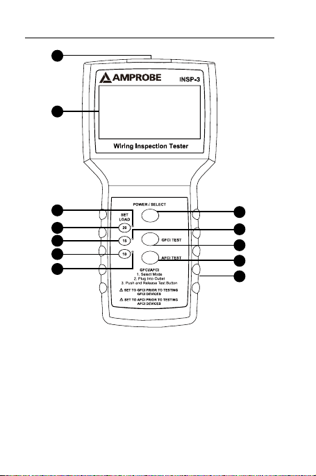
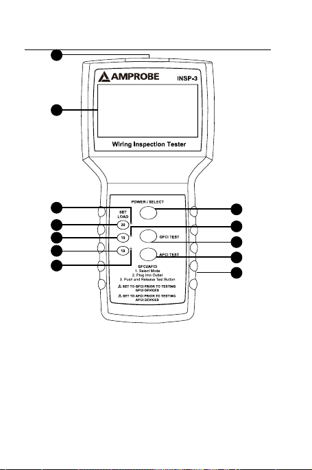
1) Power Cord Receptacle
2) Power/Select Push button
3) GFCI Test Push button
4) AFCI Test Push button
5) Battery Compartment
6) LCD Display
7) 20A load LED indicator
2
9
3
4
5
8) 20A load push button
selector
9) 15A load LED indicator
10) 15A load push button
selector
11) 10A load push button
selector
12) 10A load LED indicator
Page 7

CONTENTS
SYMBOLS ........................................................................ 2
UNPACKING AND INSPECTION ..................................... 4
INTRODUCTION .............................................................. 4
Features ...................................................................... 4
OPERATION ..................................................................... 6
Main Screen (Refer to Fig.2) ..................................... 7
Secondary Screen (Refer to Fig.3) ............................ 7
What the Readings Mean ......................................... 8
SPECIFICATION ............................................................. 11
MAINTENANCE AND REPAIR ....................................... 11
Battery Replacement .............................................. 12
1
Page 8
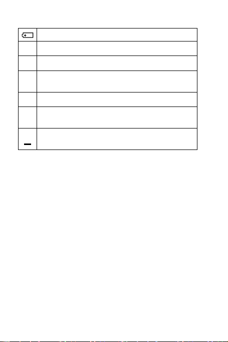
SYMBOLS
Battery
Hazardous voltage
Double Insulated
Risk of Danger. Important information.
�
See Manual.
Conforms to European Union directives.
Conforms to relevant North American Safety
Standards.
Do not dispose of this product as unsorted
=
municipal waste
Safety Information
• The INSP-3 wiring inspection Tester is conformed
to CAN/CSA-C22.2 No. 61010-1-04, UL 61010-1
(2nd Edition), CAT III 120 V, class II and pollution
degree 2.
• Do not exceed the maximum overload limits
(see specifications) nor the limits marked on the
instrument itself. Never apply more than 120
VAC rms between the adaptor prongs of the
wiring inspection tester.
2
Page 9

WARNING and PRECAUTIONS
�
• Before and after hazardous voltage
measurements, test the voltage function on a
known source such as line voltage to determine
proper meter functioning.
• Inspect the INSP-3 wiring inspection tester before
every use. Do not use any damaged part.
• Never ground yourself when taking
measurements. Do not touch exposed circuit
elements or test probe tips.
• Do not operate the instrument in an explosive
atmosphere.
• To reduce the risk of fire or electric shock, do not
expose this product to rain or moisture.
• The meter is intended only for indoor use. To
avoid electrical shock hazard, observe the proper
safety precautions when working with voltages
above 60 VDC, 42.4 Vpk, or 30 VAC rms. These
voltage levels pose a potential shock hazard to
the user.
• Before and after hazardous voltage
measurements, test the voltage function on a
known source such as line voltage to determine
proper meter functioning.
• Keep your hands/fingers behind the hand/finger
barriers (of the meter and the power cord) that
indicate the limits of safe access of the hand-held
part during measurement.
3
Page 10

UNPACKING AND INSPECTION
Your shipping carton should include:
1 INSP-3 Wiring Inspection Tester
1 Power Cord
1 9V Alkaline Battery (Installed)
1 Users Manual
1 Carrying Case
If any of the items are damaged or missing, return
the complete package to the place of purchase for an
exchange.
INTRODUCTION
The INSP-3, wiring inspector is a rugged tester
designed to verify building wiring compliance to
electrical code, especially voltage drop under load.
Identify issues with splices, connections and conductor
quality, crucial to safety and performance of the
electrical system.
Features
• Testing efficiency - relevant test data (voltage,
voltage drop, hot and neutral voltage drop,
voltage with load, ground impedance) is
presented on a single large display to save
operator time - no scrolling or switching screens
needed
• Verifies if wiring is tested for load
carrying ability that meets electrical code
recommendations for voltage drop under load
4
Page 11

• Meter detects faulty wiring in need of repair
without removing outlets cover plates, or panel
covers:
• Faulty splices and connections
• Incorrect wiring
• Undersized wiring
• Faulty GFCIs,
• Faulty or incorrectly wired AFCIs
• Incorrect line voltage
• Poor ground quality
• User selectable 10,15 and 20 amps loads to verify
performance of the electrical system
• Incorrect wiring or voltage drop test failure is
clearly indicated by flashing screen
• Will not trip circuit breakers or blow fuses
during the test
• Tests GFCI and AFCI operations
• Check ground quality for safety and ability to
support sensitive electronic equipment
• Measure fault currents
• Save money and time by eliminating guess work.
NOTE: The Inspector™ 3 does not check the
condition of wiring insulation.
5
Page 12

OPERATION
A High Quality Adaptor should be used when testing
2 wire outlets.
Ground impedance and polarity is not tested on 2 wire
outlets.
1. Push GFCI TEST push button or AFCI TEST push
button before plugging the INSP-3 to a GFCI or
AFCI circuit outlet to be tested.
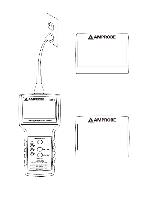
2. Plug the INSP-3 wiring inspection tester into
an energized 120V wall outlet using the power
cord provided. Refer to Fig.1
3. The unit will turn itself ON and display the test
results.
4. Push the desired Set Load push button.
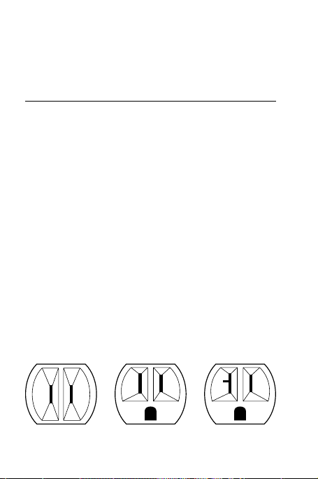
Although 10 AMP outlets don’t exist, the switch may be
set to 10 simulating a light load if a small, lower current
device will be connected to the line. Typical 2 wire, 15
AMP and 20 AMP outlets appear as follows:
2 WIRE 15 AMP 20 AMP
5. Read the test results. For GFCI and AFCI, refer to
fig.4 and fig.5
IMPORTANT: In case GFCI/AFCI breaker does not
automatically trip after pressing and releasing
GFCI/AFCI TEST button, push the “TEST” button
on the breaker under test. The breaker must
6
Page 13

trip. If it does not – do not use the breaker –
consult an electrician.
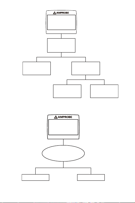
Main Screen (Refer to Fig.2)
Line 1: shows an unloaded voltage of 121.5V /
60Hz at the outlet being tested.
Line 2: shows the polarity status
Line 3: The “SET LOAD” switch is set for a test
drawing 15 amps. At 15 amps of current draw, the
voltage at the outlet would drop by 4.2%. Since
4.2% is lower than the NEC recommendation of a
maximum of 5% drop, it would not be flashing.
Line 4: shows that 1.1% of the voltage drop is on
the hot conductor while 3.1% is on the neutral
conductor.
Line 5: shows that the voltage at the outlet would
drop to 116.4 volts with a 15 amp load applied.
Line 6: shows that the resistance of the ground
conductor from the outlet to the point where it is
bonded to the neutral conductor is .27 ohms.
NOTE: The Set Load switch may be changed to
show what the drops and voltage would be at 10,
15, or 20 Amps any time after the first reading is
indicated.
Secondary Screen (Refer to Fig.3)
Line 1: shows the outlet to have a true rms voltage
of 121.5/60 Hz volts with no load applied by The
Inspector-3.
Line2: shows the polarity status
7
Page 14

Line 3: shows the common mode (the voltage
difference between the ground and neutral
conductor) to be 0.79 volts with no load applied
by the Inspector-3.
Line 4: shows that if the hot and neutral
conductors were to be shorted at the outlet,
the wiring resistance would limit the current to
approximately 424 Amps.
Line 5: shows that if the hot and ground
conductors were to be shorted at the outlet,
the wiring resistance would limit the current to
approximately 850 Amps.
NOTE: Unit turns on automatically when plugged
in. Push and release Power/Select push button to
toggle between screens.
What the Readings Mean
A) Voltage under load: This is the actual voltage
available if a steady load of 10, 15 or 20 amps is
applied to the line. Most North American devices
will operate correctly between approximately
110 and 125 volts. Voltage of less than 108 may
cause computers and other sensitive equipment
to malfunction. High or low voltage can often be
corrected by the utility company servicing your
area.
B) Voltage Drop: Indicates amount voltage would
be reduced with the set load applied to the line.
The national electrical code recommends no
more than a 5% voltage drop. Excessive voltage
drop can be caused by poor splices, connections
8
Page 15

or too small of wiring for the length of the run.
Excessive voltage drop can lead to fire, low
operating voltages, and marginal operations
of equipment. Individual conductor quality is
tested by comparing the percentage of voltage
drop on the hot and neutral conductors. This
will indicate if either the hot or the neutral has a
loose connection or if the wiring run is too long
or has too small a gauge wire for the length of
the run. The electrical code states that “. . . where
the maximum voltage drop on both feeders
and branch circuits to the farthest outlet does
not exceed 5 percent, will provide reasonably
efficiency of operation” (Sec. 210-19)
Possible problems creating excessive voltage drop:
a) Bad splice
b) Loose screw termination
c) Stripped thread on wire nuts or terminal screws
d) Faulty outlet
e) Undersize wiring (too long of run for wire size)
f) Loose connection at circuit breaker or fuse
g) Corroded connections
h) Overheating due to loose contacts
i) Faulty or poor quality push in connections on
receptacles
j) Cold forming on aluminum wiring, causing
loose connections
k) Worn switch or circuit breaker contacts.
NOTE: 15 amp systems should not be expected to
perform to 20 amp specifications
9
Page 16

C) Ground Impedance Test – This test is not related
to the “set load” switch and is not affected by
voltage drop on the line. This test simply tells you
the quality of the outlet ground. Most computers
and high technology electronics are reliant on
a good quality equipment ground for proper
operation. A typical rule of thumb is ground
resistance in most cases should be less than 2
ohms. Loose connection, splices or too small of a
ground conductor can cause high impedance. If
less than .05 ohms is indicated on a medium or
long wire run, check the test outlet for a short
between neutral and ground.
D) Polarity Test – This test checks for typical wiring
errors involving three wire outlets. Any wiring
errors should be corrected immediately before
further test of the outlet.
NOTE: Open hot is indicated by “No AC present”
Important Notes for Testing GFCI / AFCI Circuits
A) Consult the manufacturer’s installation
instructions to determine that the device is
installed in accordance with the manufacturer’s
specifications.
B) Check for correct wiring of the receptacle and
all remotely connected receptacles on the branch
circuit.
C) In case GFCI/AFCI breaker does not
automatically trip after pressing and releasing
GFCI/AFCI TEST button, push the “TEST” button on
the breaker under test. The breaker must trip. If
it does not – do not use the breaker – consult an
electrician.
10
Page 17

NOTE: A good quality 3 to 2 wire adapter may be used
to test ungrounded systems with little loss in accuracy.
Lighting or motor circuits may be tested by using a
good quality plug to clip lead adapter having not
smaller than 14 gauge wire and not longer than
4 feet.
Large power disturbances or spikes may cause
erratic readings.
SPECIFICATION
Load: Constant 0, 10,15 or 20 AMP simulation
regardless of line voltage
Operating Voltage: 95-120V AC
Power: 9V Alkaline Battery
Fuse: ½ Amp, 125V. Not user replaceable.
GFI Trip: 6.0 mA nominal to trip GFI, 30 mA to trip RCD
AFCI Trip: Up to 8, 120 Amp pulses within ½ second
period
Operating altitude: 6561 ft (2000 m)
Operating Temperature: 32 °F to 120 °F (0 °C to 50 °C)
Accuracy: +/- 2%, +/- 2 digits.
MAINTENANCE AND REPAIR
If there appears to be a malfunction during the
operation of the meter, the following steps should be
performed in order to isolate the cause of the problem.
1. Check the battery. Replace the battery
immediately when the unit doesn’t turn ON.
2. Make sure you use the power cord provided
with the unit
11
Page 18
3. Review the operating instructions for possible
mistakes in operating procedure.
Except for the replacement of the battery, repair of
the meter should be performed only by a Factory
Authorized Service Center or by other qualified
instrument service personnel. The front panel and
case can be cleaned with a mild solution of detergent
and water. Apply sparingly with a soft cloth and allow
to dry completely before using. Do not use aromatic
hydrocarbons or chlorinated solvents for cleaning.
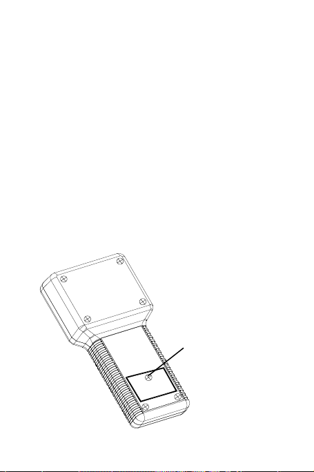
Battery Replacement
Power is supplied by 9V Alkaline Battery x1
To replace the battery, remove the screw from the
back of the meter and pull the battery door outward.
Remove the battery from case bottom and replace it
with a fresh 9V Alkaline battery.
To open,
remove screw
12
Page 19
121.5 Vrms
Polarity OK
Volt Drop @15A=4.2%
(1.1% Hot + 3.1% Neut)
Loaded Voltage =116.4
Gnd Impedance = .27e
Fig.2
60 Hz
Fig.1
121.5 Vrms
Common Mode: 0.79V
HotNeu Fault: 424A
HotGnd Fault: 850A
Polarity OK
Fig.3
13
60 Hz
Page 20
121.5V Drop@15A=3.9%
(1.5% Hot + 2.4% Neut)
Loaded Voltage=118.0
Push GFCI to trip
GFCI Breaker Test
Testing at 6mA
GFCI Breaker Test
GFCI Test passed at
6mA in 1.2 Seconds
AFCI Test passed
GFCI Breaker Test
Failed 6mA Test
Testing at 30mA
GFCI Breaker Test
GFCI Test passed at
30mA in 1.5 Seconds
Fig.4
121.5 Vrms
Volt Drop@15A=3.9%
(1.5% Hot + 2.4% Neut)
Loaded Voltage=116.8
Push AFCI to trip
Draws up to eight 120A
pulses within half period
60 Hz
Fig.5
14
GFCI Breaker Test
Failed 6mA Test
Failed 30mATest
GFCI Test Failed
AFCI Test Failed
Page 21

INSP-3
Comprobador de
inspección de cableado
Manual de uso
11/2018, 6011721 G
©2018 Amprobe Test Tools.
Reservados todos los derechos. Impreso en USA.
1
Español
Page 22

Garantía limitada y limitación de responsabilidad
Su producto Amprobe estará libre de defectos de material y
mano de obra durante 1 año a partir de la fecha de compra.
Esta garantía no cubre fusibles, baterías desechables ni
daños que sean consecuencia de accidentes, negligencia, uso
indebido, alteración, contaminación o condiciones anormales
de uso o manipulación. Los revendedores no están autorizados
a extender ninguna otra garantía en nombre de Amprobe.
Para obtener servicio durante el período de garantía,
devuelva el producto con un comprobante de compra a un
centro de servicio autorizado por Amprobe de equipos de
comprobación o a un concesionario o distribuidor de Amprobe.
Consulte la sección Reparación para obtener información
más detallada. ESTA GARANTÍA CONSTITUYE SU ÚNICO
RESARCIMIENTO. TODAS LAS DEMÁS GARANTÍAS, TANTO
EXPRESAS, IMPLÍCITAS COMO ESTATUTARIAS, INCLUYENDO
LAS GARANTÍAS IMPLÍCITAS DE IDONEIDAD PARA UN
PROPÓSITO DETERMINADO O COMERCIABILIDAD, QUEDAN
POR LA PRESENTE DESCONOCIDAS. EL FABRICANTE NO SERÁ
RESPONSABLE DE NINGÚN DAÑO O PÉRDIDA, YA SEA ESPECIAL,
INDIRECTO, CONTINGENTE O RESULTANTE QUE SURJA DE
CUALQUIER CAUSA O TEORÍA. Debido a que determinados
estados o países no permiten la exclusión o limitación de una
garantía implícita o de los daños contingentes o resultantes,
esta limitación de responsabilidad puede no regir para usted.
Reparación
Todas las herramientas de prueba devueltas para reparación
bajo la garantía o fuera de garantía, o devueltas para
calibración, deben ir acompañadas de lo siguiente: su nombre,
el nombre de su compañía, la dirección, el número de teléfono
y la prueba de compra. Además, incluya una breve descripción
del problema o del servicio solicitado y los conductores de
prueba del medidor. Los gastos en concepto de reparación
o reemplazo fuera de garantía deben remitirse en forma de
cheque, giro postal, tarjeta de crédito con fecha de vencimiento
o una orden de compra pagadera a Amprobe
®
Test Tools.
Page 23

Reparaciones y reemplazos cubiertos por la garantía
(todos los países)
Sírvase leer la declaración de garantía y compruebe su batería
antes de solicitar la reparación. Durante el período de garantía,
cualquier herramienta de comprobación defectuosa puede
ser devuelta a su distribuidor de Amprobe® Test Tools para un
intercambio por el mismo producto u otro similar. Consulte
la sección “Where to Buy” en www.amprobe.com para ver
una lista de distribuidores locales. Asimismo, las unidades de
reparación en garantía y de reemplazo en Estados Unidos
y Canadá también pueden enviarse al centro de servicio
Amprobe® Test Tools (consulte la dirección más abajo).
Reparaciones y reemplazos no cubiertos por la garantía
(Estados Unidos y Canadá)
Las reparaciones fuera de la garantía en Estados Unidos
y Canadá deben enviarse a un centro de servicio de
Amprobe® Test Tools. Llame a Amprobe® Test Tools o consulte
en su punto de compra para conocer las tarifas actuales de
reparación y reemplazo.
En EE.UU. En Canadá
Amprobe Test Tools Amprobe Test Tools
Everett, WA 98203 Mississauga, ON L4Z 1X9
Tel.: 877-AMPROBE (267-7623) Tel.: 905-890-7600
Reparaciones y reemplazos no cubiertos por la garantía (Europa)
El distribuidor de Amprobe® Test Tools puede reemplazar las
unidades vendidas en Europa no cubiertas por la garantía por
un costo nominal. Consulte la sección “Where to Buy” en
www.amprobe.com para ver una lista de distribuidores locales.
Dirección para envío de correspondencia en Europa*
Amprobe® Test Tools Europe
In den Engematten 14
79286 Glottertal, Alemania
Tel.: +49 (0) 7684 8009-0
*(Correspondencia solamente. En esta dirección no se
proporcionan reparaciones ni reemplazos. Los clientes europeos
deben ponerse en contacto con su distribuidor).
Page 24
Comprobador de inspección de cableado
INSP-3
1
6
7
8
10
11
12
1) Receptáculo para el
cable eléctrico
2) Botón Power/Select
3) Botón para pruebas de GFCI
4) Botón para pruebas de AFCI
5) Compartimento de la batería
6) Pantalla LCD
7) Indicador LED de carga de
20 A
2
9
3
4
5
8) Selector del botón de
carga de 20 A
9) Indicador LED de carga
de 15 A
10) Selector del botón de
carga de 15 A
11) Selector del botón de
carga de 10 A
12) Indicador LED de carga
de 10 A
Page 25

ÍNDICE
SÍMBOLOS ....................................................................... 2
DESEMBALAJE E INSPECCIÓN ........................................ 4
INTRODUCCIÓN .............................................................. 4
Funciones .................................................................... 4
FUNCIONAMIENTO ......................................................... 6
Pantalla principal (véase la figura 2) ........................ 7
Pantalla secundaria (véase la figura 3) ..................... 8
Lo que significan las lecturas ..................................... 8
ESPECIFICACIONES ....................................................... 11
MANTENIMIENTO Y REPARACIÓN .............................. 12
Reemplazo de la batería .......................................... 13
1
Page 26

SÍMBOLOS
Pila
Voltaje peligroso
Doble aislamiento
Riesgo de peligro. Información importante.
�
Consulte el manual.
Está conforme con la normativa de seguridad
relevante en América del Norte.
No deseche este producto sin que sea tratado
=
de forma separada del resto de desechos
Información relacionada con la seguridad
• El comprobador de inspección de cableado
INSP-3 cumple la norma CAN/CSA-C22.2 Nº.
61010-1-04, UL 61010-1 (2ª edición), CAT III 120 V,
clase II y grado de contaminación 2.
• No sobrepase los límites máximos de sobrecarga
(consulte las especificaciones) ni los límites
marcados en el propio instrumento. Nunca
aplique más de 120 V CA rms entre las patillas
del adaptador del comprobador de inspección
de cableado.
2
Page 27

ADVERTENCIAS y PRECAUCIONES
�
• Antes y después de realizar mediciones de
voltaje peligroso, compruebe la función de
voltaje en una fuente conocida, tal como el
voltaje de línea, para determinar el correcto
funcionamiento del multímetro.
• Inspeccione el comprobador de inspección de
cableado INSP-3 antes de cada uso. No lo utilice
si existe alguna pieza averiada.
• Asegúrese de no estar conectado a tierra
mientras mide. No toque los elementos
expuestos de los circuitos ni las puntas de las
sondas de prueba.
• No utilice el instrumento en una atmósfera
explosiva.
• Para reducir el riesgo de incendio o descarga
eléctrica, no exponga este producto a la lluvia o
a la humedad.
• El instrumento está destinado únicamente a uso
en interiores. Para evitar los riesgos de descarga
eléctrica, observe las precauciones correctas de
seguridad al trabajar con tensiones de más de
60 V de CC, 42,4 V pico o 30 V de CA rms. Estos
niveles de tensión presentan un potencial peligro
de descarga eléctrica al usuario.
• Antes y después de realizar mediciones de
voltaje peligroso, compruebe la función de
voltaje en una fuente conocida, tal como el
voltaje de línea, para determinar el correcto
funcionamiento del multímetro.
3
Page 28

• Mantenga sus manos/dedos detrás de los
protectores correspondientes (del medidor y del
cable de alimentación eléctrica) que indican los
límites de acceso seguro de la parte sujetada
manualmente durante la medición.
DESEMBALAJE E INSPECCIÓN
La caja de envío debe incluir:
1 Comprobador de inspección de cableado INSP-3
1 Cable de alimentación eléctrica
1 Batería alcalina de 9 V (instalada)
1 Manual de uso
1 Estuche de transporte
Si alguno de los elementos estuviera dañado o faltara,
devuelva el paquete completo al lugar de compra
para cambiarlo.
INTRODUCCIÓN
El inspector de cableado INSP-3 es un comprobador
robusto diseñado para verificar el cumplimiento
normativo del cableado de edificios según el código
eléctrico, especialmente la caída de tensión bajo carga.
Identifique problemas con empalmes, conexiones
y calidad del conductor, ya que se trata de algo
esencial para la seguridad y el funcionamiento del
sistema eléctrico.
Funciones
• Eficiencia de las pruebas: los datos de prueba
relevantes (tensión, caída de tensión, caída
de tensión con corriente y neutra, tensión con
carga, impedancia de tierra) se presentan en
4
Page 29

una pantalla única de gran tamaño para ahorrar
tiempo al operador, sin necesidad de desplazar
ni alternar pantallas
• Verifica si se comprueba el cableado para
capacidad de transporte de carga que cumpla las
recomendaciones del código eléctrico para caída
de tensión bajo carga
• El instrumento detecta un cableado defectuoso
que requiere reparación sin desmontar las placas
protectoras de las tomas de corriente ni las
cubiertas de los paneles:
• Empalmes y conexiones defectuosos
• Cableado incorrecto
• Cableado subdimensionado
• GFCI defectuosos
• AFCI defectuosos o incorrectamente cableados
• Tensión de línea incorrecta
• Calidad de tierra deficiente
• Cargas de 10, 15 y 20 amps seleccionables por
el usuario para verificar el funcionamiento del
sistema eléctrico
• Se indica claramente el cableado incorrecto o el
fallo de la prueba de caída de tensión mediante
la pantalla parpadeante
• No activa los disyuntores ni quema fusibles
durante la prueba
• Prueba las operaciones de los GFCI y AFCI
• Verifique la calidad de la tierra en cuanto a
seguridad y capacidad de soportar el equipo
electrónico
• Mida corrientes de fallo
5
Page 30
• Ahorre dinero y tiempo al eliminar la necesidad
de adivinar dónde se encuentra el problema.
NOTA: El Inspector™ 3 no verifica el estado del
aislamiento del cableado.
FUNCIONAMIENTO
Debe usarse un adaptador de alta calidad al comprobar
tomas de corriente de 2 hilos.
No se comprueba la impedancia de tierra ni la polaridad en las tomas de corriente de 2 hilos.
1. Pulse el botón GFCI TEST o el botón AFCI TEST antes de enchufar el INSP-3 a la toma de corriente
de circuito de GFCI o AFCI que desee comprobar.
2. Enchufe el comprobador de inspección de
cableado INSP-3 a una toma de corriente de
pared de 120 V que reciba electricidad por
medio del cable eléctrico provisto. Véase la fig. 1.
3. La unidad se encenderá y mostrará los resultados
de la prueba.
4. Pulse el botón Set Load deseado para establecer
la carga.
Aunque no hay tomas de corriente de 10 AMP, el
interruptor puede configurarse en 10 simulando una
carga ligera si se conectará a la línea un dispositivo pequeño que utilice corriente inferior. Las típicas tomas de
corriente de 2 hilos, de 15 y 20 AMP, tiene este aspecto:
2 HILOS 15 AMP 20 AMP
6
Page 31

5. Lea los resultados de la prueba. Para GFCI y
AFCI, véanse las figuras 4 y 5.
IMPORTANTE: Si el disyuntor no se activa
automáticamente después de pulsar y soltar el
botón GFCI/AFCI TEST, pulse el botón “TEST“
del disyuntor a comprobar. El disyuntor debe
activarse. Si no lo hace, no utilice el disyuntor;
consulte a un electricista.
Pantalla principal
Línea 1: muestra una tensión sin carga de 121,5 V
/ 60 Hz en la toma de corriente que se somete
a prueba.
Línea 2: muestra el estado de polaridad.
Línea 3: el interruptor “SET LOAD” se establece
para una prueba que requiere 15 amps. A 15 amps
de corriente, la tensión presente en la toma de
corriente disminuiría en un 4,2 %. El 4,2 % no
parpadearía, ya que es inferior a la recomendación
de NEC de una caída máxima del 5 %.
Línea 4: muestra que el 1,1 % de la caída de
tensión se encuentra en el conductor activo
mientras que el 3,1 % se encuentra en el
conductor neutro.
Línea 5: indica que la tensión presente en la toma
de corriente disminuiría a 116,4 voltios con la
aplicación de una carga de 15 amp.
Línea 6: indica que la resistencia del conductor de
tierra desde la toma de corriente hasta el punto en
donde se encuentra unido al conductor neutro es
de 0,27 ohmios.
NOTA: el interruptor Set Load puede cambiarse
para mostrar los valores de las caídas y de la
tensión a 10, 15 ó 20 amps en cualquier momento
después de indicarse la primera lectura.
(véase la figura 2)
7
Page 32

Pantalla secundaria (véase la figura 3)
Línea 1: muestra que la toma de corriente tiene
una tensión con un verdadero valor eficaz de
121,5/60 Hz voltios sin ninguna carga aplicada por
el instrumento Inspector-3.
Línea 2: muestra el estado de polaridad.
Línea 3: muestra el modo común (la diferencia de
tensión entre el conductor de tierra y el neutro)
con un valor de 0,79 voltios sin carga aplicada por
el instrumento Inspector-3.
Línea 4: muestra que si se colocaran en
cortocircuito los conductores activo y neutro
de la toma de corriente, la resistencia del
cableado limitaría la corriente a un valor de
aproximadamente 424 amps.
Línea 5: muestra que si se colocaran en
cortocircuito los conductores activo y tierra
de la toma de corriente, la resistencia del
cableado limitaría la corriente a un valor de
aproximadamente 850 amps.
NOTA: la unidad se enciende automáticamente al
enchufarla. Pulse y suelte el botón Power/Select
para alternar entre las pantallas.
Lo que significan las lecturas
A) Tensión bajo carga: se trata de la tensión
real disponible si se aplica a la línea una carga
permanente de 10, 15 ó 20 amps. La mayoría de
los dispositivos en América del Norte funcionan
correctamente entre aproximadamente 110 y
125 voltios. Una tensión inferior a 108 puede causar
un funcionamiento defectuoso de ordenadores y
otros equipos sensibles. Muchas veces, la tensión
alta o baja puede corregirla la empresa de servicios
eléctricos responsable de su zona.
8
Page 33

B) Caída de tensión: indica la cantidad en que
se reduciría la tensión con la carga establecida
aplicada a la línea. El código eléctrico nacional
recomienda una caída de tensión inferior al 5 %.
Una caída de tensión excesiva puede tener su
origen en deficiencias de empalmes y conexiones,
o en un cableado demasiado pequeño para toda
la longitud del tramo. Una caída excesiva de
tensión puede ocasionar incendios, tensiones
operativas bajas y funcionamiento marginal de
los equipos. La calidad del conductor individual
se comprueba comparando el porcentaje de caída
de tensión en los conductores activo y neutro.
Esto indicará si el conductor activo o neutro tiene
una conexión suelta o si el tramo del cableado
es demasiado largo o tiene un hilo de calibre
demasiado pequeño para la longitud del tramo. El
código eléctrico indica que “. . . donde la máxima
caída de tensión, tanto en los alimentadores como
en los circuitos de ramificación, hasta la toma de
corriente más lejana no supere el 5 por ciento, la
eficiencia operativa será razonable” (Sec. 210-19).
Problemas posibles que crean una caída excesiva
de tensión:
a) Empalme defectuoso
b) Terminación de tornillo suelto
c) Rosca desgastada en tuercas del hilo o tornillos
terminales
d) Toma de corriente defectuosa
e) Cableado subdimensionado (tramo demasiado
largo para el tamaño de hilo)
f) Conexión suelta en el disyuntor o fusible
9
Page 34

g) Conexiones corroídas
h) Sobrecalentamiento debido a contactos sueltos
i) Conexiones de compresión defectuosas o de
calidad deficiente en los receptáculos
j) Conformación en frío en cableado de aluminio,
lo que produce conexiones sueltas
k) Contactos desgastados en el interruptor
o disyuntor.
NOTA: no se debe contar con que los sistemas de
15 amp funcionen conforme a las especificaciones
para 20 amp.
C) Prueba de impedancia de tierra: esta prueba
no está relacionada con el interruptor de
“establecimiento de la carga” y no se ve afectada
por la caída de tensión en la línea. Esta prueba
simplemente le indica la calidad de la tierra de la
toma de corriente. La mayoría de los ordenadores
y componentes electrónicos de alta tecnología
dependen de que el equipo tenga una buena
conexión a tierra de buena calidad para su
correcto funcionamiento. Una típica regla práctica
es que la resistencia de tierra en la mayoría de
los casos debe ser de inferior a 2 ohmios. Una
conexión o empalmes sueltos, o un conductor a
tierra demasiado pequeño, pueden causar una alta
impedancia. Si se indican menos de 0,05 ohmios
en un tramo de hilo mediano o largo, verifique la
toma de corriente de prueba para determinar si
hay un cortocircuito entre el neutro y la tierra.
D) Prueba de polaridad: esta prueba verifica la
existencia de los errores de cableado comunes en
tomas de corriente de tres hilos. Cualquier error de
cableado deberá corregirse inmediatamente antes
de realizar otras pruebas de la toma de corriente.
10
Page 35

NOTA: los cables activos abiertos se indican con el
mensaje “No AC present”.
Notas importantes para comprobar circuitos
GFCI / AFCI
A) Consulte las instrucciones de instalación del
fabricante para determinar que el dispositivo
esté instalado de acuerdo con las especificaciones
del fabricante.
B) Verifique un correcto cableado del receptáculo
y de todos los receptáculos conectados
remotamente en el circuito de ramificación.
C) Si el disyuntor no se activa automáticamente
después de pulsar y soltar el botón GFCI/AFCI TEST,
pulse el botón “TEST” del disyuntor a comprobar. El
disyuntor debe activarse. Si no lo hace, no utilice el
disyuntor; consulte a un electricista.
NOTA: puede usarse un adaptador de 3 a 2 hilos
de buena calidad para comprobar sistemas
subterráneos con poca pérdida de exactitud.
Es posible comprobar circuitos de iluminación o de
motores utilizando un adaptador de conector a
conductor de pinza de buena calidad con un hilo
que no sea inferior al calibre 14 y con una longitud
inferior a 1,2 metros (4 pies).
Las perturbaciones o picos grandes de energía
pueden causar lecturas erráticas.
ESPECIFICACIONES
Carga: simulación constante de 0, 10, 15 ó 20 AMP
independientemente de la tensión de línea
Tensión de funcionamiento: 95-120 V CA
11
Page 36

Alimentación: 1 Batería alcalina de 9 V
Fusible: ½ amp, 125 V; no es reemplazable por
el usuario
Conmutación de GFI: 6,0 mA nominales para conmutar
GFI, 30 mA para conmutar RCD
Conmutación de AFCI: hasta 8 pulsos de 120 amperios
dentro de un período de ½ segundo
Altitud de funcionamiento: 2000 metros
Temperatura de funcionamiento: 0 °C a 50 °C
(32 °F a 120 °F)
Exactitud: +/- 2 %, +/- 2 dígitos
MANTENIMIENTO Y REPARACIÓN
Si parece que el medidor no funciona bien, realice los
pasos siguientes para identificar la causa del problema:
1. Compruebe la batería. Reemplace la batería
inmediatamente cuando la unidad no se
encienda.
2. Asegúrese de utilizar el cable eléctrico provisto
con la unidad.
3. Repase las instrucciones de funcionamiento
por si hubiera cometido algún error en algún
procedimiento.
Excepto el cambio de la batería, cualquier otra
reparación del medidor deberá llevarla a cabo
exclusivamente un centro de servicio autorizado por
la fábrica u otro personal cualificado para reparación
de instrumentos. El panel frontal y la carcasa pueden
limpiarse con una solución suave de detergente y
agua. Aplique sólo un poquito de dicha solución con
un paño suave y séquelo por completo antes de su
utilización. No utilice hidrocarburos aromáticos ni
solventes clorados para la limpieza.
12
Page 37

Reemplazo de la batería
Se suministra energía por medio de una batería
alcalina de 9 V.
Para reemplazar la batería, quite el tornillo de la parte
posterior del instrumento y deslice la puerta de la
batería hacia afuera.
Retire la batería de la parte inferior de la caja y
reemplácela con una batería alcalina nueva de 9 V.
Para abrir,
quite el tornillo
13
Page 38

121.5 Vrms
Polarity OK
Volt Drop @15A=4.2%
(1.1% Hot + 3.1% Neut)
Loaded Voltage =116.4
Gnd Impedance = .27e
Fig. 2
60 Hz
Fig. 1
121.5 Vrms
Common Mode: 0.79V
HotNeu Fault: 424A
HotGnd Fault: 850A
Polarity OK
Fig. 3
14
60 Hz
Page 39

Fig. 4
Fig. 5
15
Page 40

Page 41

INSP-3
Inspecteur de câblage
Mode d’emploi
11/2018, 6011721 G
©2018 Amprobe Test Tools.
Tous droits réservés. Imprimé au États - unis.
Français
Page 42

Limites de garantie et de responsabilité
Amprobe garantit l’absence de vices de matériaux et de
fabrication de ce produit pendant une période d’un an
prenant effet à la date d’achat. Cette garantie ne s’applique
pas aux fusibles, aux piles jetables ni à tout produit mal
utilisé, modifié, contaminé, négligé ou endommagé par
accident ou soumis à des conditions anormales d’utilisation
et de manipulation. Les revendeurs n’ont pas l’autorisation
de prolonger toute autre garantie au nom d’Amprobe. Pour
bénéficier de la garantie, renvoyez le produit accompagné
d’un justificatif d’achat auprès d’un centre de services agréé
par Amprobe Test Tools ou d’un distributeur ou d’un revendeur
Amprobe. Voir la section Réparation pour tous les détails.
LA PRESENTE GARANTIE EST LE SEUL ET EXCLUSIF RECOURS
DE L’UTILISATEUR. TOUTES AUTRES GARANTIES, EXPLICITES,
IMPLICITES OU STATUTAIRES, NOTAMMENT LES GARANTIES
DE QUALITE MARCHANDE OU D’ADAPTATION A UN OBJECTIF
PARTICULIER SONT EXCLUES PAR LES PRESENTES. LE FABRICANT
NE SERA EN AUCUN CAS TENU RESPONSABLE DE DOMMAGES
PARTICULIERS, INDIRECTS, ACCIDENTELS OU CONSECUTIFS, NI
D’AUCUNS DEGATS OU PERTES DE DONNEES, SUR UNE BASE
CONTRACTUELLE, EXTRA-CONTRACTUELLE OU AUTRE. Etant
donné que certaines juridictions n’admettent pas les limitations
d’une condition de garantie implicite ou l’exclusion ou la
limitation de dégâts accidentels ou consécutifs, il se peut que
les limitations et les exclusions de cette garantie ne s’appliquent
pas à votre cas.
Réparation
Tous les outils de test renvoyés pour être réparés au titre de
la garantie doivent être accompagnés des éléments suivants :
nom, raison sociale, adresse, numéro de téléphone et justificatif
d’achat. Ajoutez également une brève description du problème
ou du service demandé et incluez les cordons de test avec
l’appareil. Les frais de remplacement ou de réparation hors
garantie doivent être acquittés par chèque, mandat, carte de
crédit avec date d’expiration, ou par bon de commande payable
à l’ordre de Amprobe
®
Test Tools.
Page 43

Remplacements et réparations sous garantie – Tous pays
Veuillez lire la déclaration de garantie et vérifiez la pile avant
de demander une réparation. Pendant la période de garantie,
tout outil de test défectueux peut être renvoyé auprès de votre
distributeur Amprobe® Test Tools pour être échangé contre un
produit identique ou similaire. Consultez la section « Where
to Buy » sur le site www.amprobe.com pour obtenir la liste
des distributeurs dans votre région. Les appareils sous garantie
devant être remplacés ou réparés au Canada et aux Etats-Unis
peuvent également être envoyés dans un centre de services
Amprobe® Test Tools (voir les adresses ci-dessous).
Remplacements et réparations hors garantie – Canada et
Etats-Unis
Les appareils à réparer hors garantie au Canada et aux
Etats-Unis doivent être envoyés dans un centre de services
Amprobe® Test Tools. Appelez Amprobe® Test Tools ou
renseignez-vous auprès de votre lieu d’achat pour connaître
les tarifs en vigueur de remplacement ou de réparation.
Aux Etats-Unis Au Canada
Amprobe Test Tools Amprobe Test Tools
Everett, WA 98203 Mississauga, ON L4Z 1X9
Tél. : 877-AMPROBE (267-7623) Tél. : 905-890-7600
Remplacements et réparations hors garantie – Europe
Les appareils européens non couverts par la garantie peuvent
être remplacés par votre distributeur Amprobe® Test Tools pour
une somme nominale. Consultez la section « Where to Buy » sur
le site www.amprobe.com pour obtenir la liste des distributeurs
dans votre région.
Adresse postale européenne*
Amprobe® Test Tools Europe
In den Engematten 14
79286 Glottertal, Allemagne
Tél. : +49 (0) 7684 8009-0
*(Réservée à la correspondance – Aucune réparation ou
remplacement n’est possible à cette adresse. Nos clients
européens doivent contacter leur distributeur.)
Page 44

Inspecteur de câblage INSP-3
1
6
7
8
10
11
12
1) Prise du cordon
d’alimentation
2) Bouton-poussoir Power/
Select
3) Bouton-poussoir de test GFCI
4) Bouton-poussoir de test AFCI
5) Couvercle de pile
6) Ecran LCD
7) Témoin indicateur 20 A
de charge
2
9
3
4
5
8) Sélecteur à boutonpoussoir 20 A de charge
9) Témoin indicateur 15 A
de charge
10) Sélecteur à bouton-
poussoir 15 A de charge
11) Sélecteur à bouton-
poussoir 10 A de charge
12) Témoin indicateur 10 A
de charge
Page 45

TABLE DES MATIERES
SYMBOLES ...................................................................... 2
DEBALLAGE ET INSPECTION .......................................... 4
INTRODUCTION .............................................................. 4
Fonctionnalités ........................................................... 4
FONCTIONNEMENT ........................................................ 6
Ecran principal (se reporter à la Fig. 2) ..................... 7
Ecran secondaire (se reporter à la Fig. 3) ................. 7
Que signifient les valeurs relevées ............................ 8
CARACTERISTIQUES ..................................................... 11
ENTRETIEN ET REPARATION ......................................... 12
Changement de la pile ............................................ 13
1
Page 46

SYMBOLES
Pile
Tension dangereuse
Isolation double
Risque de danger. Information importante.
�
Consulter le manuel.
Conforme aux normes de sécurité nord
américaines applicables.
Ne jetez pas ce produit avec des déchets
=
municipaux non triés
Consignes de sécurité
• L’inspecteur de câblage INSP-2 est conforme
à CAN/CSA-C22.2 N° 61010-1-04, UL 61010-1
(2e édition), CAT III 120 V, classe II et degré de
pollution 2.
• Ne pas dépasser les limites de surcharge maximum
(voir les caractéristiques techniques) ou les limites
indiquées sur l’appareil lui-même. Ne jamais
appliquer plus de 120 V c.a. eff. entre les broches
de l’adaptateur de l’inspecteur de câblage.
2
Page 47

MISES EN GARDE et PRECAUTIONS
�
• Avant et après les mesures de tensions
dangereuses, tester la fonction de tension sur
une source connue, une tension secteur p. ex.,
pour déterminer le bon fonctionnement de
l’appareil.
• Examiner l’inspecteur de câblage INSP-3
avant chaque emploi. Ne pas utiliser de pièce
endommagée.
• Ne jamais se relier à la terre lors de la prise de
mesures. Ne toucher ni aux éléments de circuit
exposés ni aux pointes des sondes de test.
• Ne pas utiliser l’appareil dans une atmosphère
explosive.
• Pour réduire le risque d’incendie ou
d’électrocution, ne pas exposer cet appareil à
l’humidité ou à la pluie.
• L’appareil est destiné à être utilisé à l’intérieur
uniquement. Pour éviter les chocs électriques,
observer les précautions de sécurité appropriées
en intervenant sur des tensions supérieures à
60 V c.c., 42,4 V cr. ou 30 V. c.a. eff. Ces niveaux
de tension présentent un risque d’électrocution
pour l’utilisateur.
• Avant et après les mesures de tensions
dangereuses, tester la fonction de tension
sur une source connue, une tension secteur
p. ex., pour déterminer le bon fonctionnement
de l’appareil.
• Garder les mains/doigts derrière les collerettes
de protection (de l’appareil et du cordon
d’alimentation) qui indiquent les limites de
sécurité de l’appareil et des cordons pendant
la mesure.
3
Page 48

DEBALLAGE ET INSPECTION
Le carton d’emballage doit inclure les éléments
suivants :
1 Inspecteur de câblage INSP-3
1 Cordon d’alimentation
1 Pile de 9 V (installée)
1 Mode d’emploi
1 Mallette de transport
Si l’un de ces éléments est endommagé ou manquant,
renvoyez le contenu complet de l’emballage au lieu
d’achat pour l’échanger.
INTRODUCTION
L’inspecteur de câblage INSP-3 est un appareil d’essai
robuste conçu pour vérifier la conformité des fils
de câblage d’un bâtiment avec le code national de
l’électricité, notamment les chutes de tension en
charge. Identifiez les anomalies liées aux épissures,
aux branchements et à la qualité des conducteurs, qui
sont cruciales pour la sécurité et les performances du
système électrique.
Fonctionnalités
• Efficacité des tests - Les données de test
pertinentes (tension, chute de tension, chute de
tension aux points neutre et chaud, tension sous
charge, impédance à la terre) sont présentées
sur grand écran pour faire gagner du temps à
l’opérateur qui n’a pas besoin de faire défiler ou
de permuter les écrans
• Vérifie si le fils de câblage testé sur sa
capacité de transport de charge répond
4
Page 49

aux recommandations du code national de
l’électricité pour la chute de tension en charge
• L’appareil détecte les fils de câblage défectueux
à réparer sans retirer les plaques de protection
des prises, ou les capots des panneaux :
• Epissures et branchements défectueux
• Câblage incorrect
• Câblage sous-dimensionné
• Disjoncteurs de fuite à la terre (GFCI) défectueux
• Disjoncteurs de défaut d’arc (AFCI) défectueux
ou incorrects
• Tension secteur incorrecte
• Mauvaise qualité de la terre
• Charges de 10, 15 et 20 A que l’utilisateur peut
sélectionner pour vérifier les performances du
système électrique
• La présence d’un défaut lors d’un test de
chute de tension ou de câblage est clairement
indiquée par un affichage clignotant
• Ne déclenche pas de disjoncteurs ni ne fait
sauter de fusibles pendant le test
• Vérifie le fonctionnement des disjoncteurs GFCI
et AFCI
• Vérifie la qualité de la prise de terre pour la
sécurité et sa capacité à prendre en charge des
équipements électroniques sensibles
• Mesure les courants de défaut
• Economies de temps et d’argent en évitant les
estimations
REMARQUE : L’Inspector™ 3 ne vérifie pas la
condition de l’isolant du câblage.
5
Page 50

FONCTIONNEMENT
Un adaptateur de haute qualité doit être utilisé pour
tester les prises à 2 fils.
L’impédance à la terre et la polarité ne sont pas testées
sur les prises à 2 fils.
1. Enfoncez le bouton GFCI TEST ou AFCI TEST
avant de brancher l’INSP-3 dans la prise du
circuit GFCI ou AFCI à tester.
2. Branchez l’inspecteur de câblage INSP-3 dans
une prise murale de 120 V sous tension en
utilisant le cordon d’alimentation fourni.
Reportez-vous à la Fig. 1.
3. L’appareil s’allume et affiche les résultats du test.
4. Enfoncez le bouton-poussoir Set Load souhaité.
Même si des prises de 10 A n’existent pas, le sélecteur
peut être réglé sur 10 pour simuler une charge légère si
un petit appareil d’intensité inférieure doit être branché
sur la ligne. Les prises typiques à 2 fils, de 15 et 20 A sont
affichées comme suit :
2 FILS 15 A 20 A
5. Lisez les résultats du test. Pour les disjoncteurs
GFCI et AFCI, reportez-vous aux Fig. 4 et Fig. 5.
IMPORTANT : Si le disjoncteur GFCI/AFCI ne
se déclenche pas automatiquement après
avoir enfoncé puis relâché le bouton de
test GFCI/AFCI, appuyez sur le bouton TEST
6
Page 51

du disjoncteur testé. Le disjoncteur doit se
déclencher. Si ce n´est pas le cas, n´utilisez pas
le disjoncteur et consultez un électricien.
Ecran principal (se reporter à la Fig. 2)
Ligne 1 : indique une tension non chargée de
121,5 V / 60 Hz à la prise testée.
Ligne 2 : indique l’état de la polarité
Ligne 3 : le sélecteur « SET LOAD » est réglé pour
un appel de 15 A lors du test. Avec un appel
de courant de 15 A, la tension au niveau de la
prise chuterait de 4,2 %. Comme le chiffre de
4,2 % est inférieur à la chute maximum de 5 %
recommandée par le Code national de l’électricité
(NEC), l’affichage ne clignoterait pas.
Ligne 4 : indique que 1,1 % de la chute de tension
se produit sur le fil chaud et 3,1 % sur le fil neutre.
Ligne 5 : indique que la tension au niveau de la
prise tomberait à 116,4 V si une charge de 15 A
était appliquée.
Ligne 6 : indique que la résistance du fil de terre
entre la prise et le point où il est relié au neutre
est de 0,27 ohms.
REMARQUE : le sélecteur Set Load peut être
déplacé pour indiquer quelles seraient les chutes
de tension et le potentiel à 10, 15 ou 20 A à
un moment donné après l’apparition de la
première valeur.
Ecran secondaire (se reporter à la Fig. 3)
Ligne 1 : indique que la prise montrerait une
tension eff. vraie de 121,5 V / 60 Hz sans charge
7
Page 52

appliquée par l’Inspector-3.
Ligne 2 : indique l’état de la polarité.
Ligne 3 : indique que le mode commun (la
différence de tension entre les fils neutre et la
terre) serait de 0,79 V sans charge appliquée par
l’Inspector-3.
Ligne 4 : indique que si les fils neutre et chaud
étaient en court-circuit au niveau de la prise, la
résistance du fil limiterait le courant à environ
424 A.
Ligne 5 : indique que si les fils neutre et chaud
étaient en court-circuit au niveau de la prise, la
résistance du fil limiterait le courant à environ
850 A.
REMARQUE : l’appareil se met automatiquement
en marche dès qu’il est branché. Enfoncez le
bouton-poussoir Power/Select et relâchez-le pour
basculer d’un écran à l’autre.
Ce que signifient les valeurs relevées
A) Tension en charge : il s’agit de la tension réelle
disponible si une charge stable de 10, 15 ou 20 A
est appliquée sur la ligne. La plupart des appareils
nord-américains fonctionnent correctement entre
environ 110 et 125 V. Une tension inférieure à 108
peut provoquer le mauvais fonctionnement des
ordinateurs ou d’autres équipements sensibles. La
tension haute ou basse peut souvent être corrigée
par la compagnie d’électricité qui dessert la zone.
B) Chute de tension : indique le niveau de
réduction de tension si la charge définie était
appliquée à la ligne. Le code national de
l’électricité recommande une chute de tension
8
Page 53

égale ou inférieure à 5 %. Une chute de tension
excessive peut être induite par des épissures ou
des branchements médiocres, ou une longueur
de fil trop petite pour le câblage prévu. Une
chute de tension excessive peut entraîner un
incendie, des basses tensions d’exploitation et un
fonctionnement aux marges de l’équipement. La
qualité individuelle du fil est testée en comparant
le pourcentage de la chute de tension sur les fils
chaud et neutre. Cette comparaison indique si
le fil chaud ou neutre présente une connexion
desserrée ou si le fil prévu est trop long ou d’un
calibre trop petit pour la longueur de câblage
prévue. Le code de l’électricité déclare que
« . . . l’exploitation sera la plus raisonnablement
performante quand la chute de tension maximale
sur les câbles d’alimentation et les circuits de
dérivation vers la prise la plus éloignée ne
dépassera pas 5 % » (Sec. 210-19).
Anomalies possibles en créant une chute de
tension excessive :
a) Epissure défectueuse
b) Vis de serrage desserrée
c) Filets foirés sur les serre-fils ou les vis de serrage
d) Prise défectueuse
e) Fil sous-dimensionné (trop long pour le calibre
du fil)
f) Branchement desserré au niveau du disjoncteur
ou le fusible
g) Branchements corrodés
h) Surchauffe due à des contacts desserrés
9
Page 54

i) Qualité d’insertion défectueuse ou médiocre
des branchements sur les prises
j) Formage à froid sur les fils en aluminium
entraînant des branchements desserrés
k) Interrupteur ou contacts de disjoncteur usés
REMARQUE : les systèmes à 15 A ne sont pas
prévus pour fonctionner selon les spécifications
20 A.
C) Test d’impédance à la terre : ce test n’est pas lié
au sélecteur « Set Load » et n’est pas affecté par
une chute de tension sur la ligne. Il vous indique
simplement la qualité de la terre de protection
de la prise. La plupart des ordinateurs et des
appareils électroniques de haute technologie
sont tributaires de la bonne qualité de la mise
à la masse des équipements pour leur bon
fonctionnement. Il existe une règle de vérification
toute simple : la résistance à la terre doit être
inférieure à 2 ohms dans la plupart des cas.
Les connexions desserrées, les épissures ou une
longueur de fil de terre trop petite peut entraîner
une impédance élevée. Si l’appareil indique une
résistance inférieure à 0,05 ohms sur une longueur
de fil longue ou intermédiaire, recherchez la
présence d’un court-circuit entre le neutre et la
terre sur la prise testée.
D) Test de polarité : ce test recherche les erreurs
de fils de câblage typiques sur les prises trifilaires.
Toutes les erreurs de fils de câblage doivent
être corrigées immédiatement avant de tester
davantage la prise.
REMARQUE : un fil chaud coupé est indiqué par la
mention « No AC present » (« Pas de c.a. »).
10
Page 55

Remarques importantes sur les tests de circuits
GFCI / AFCI
A) Reportez-vous aux instructions d’installation du
fabricant pour déterminer si le dispositif installé
répond aux spécifications du fabricant.
B) Confirmez le câblage du fil dans la prise et
sur toutes les prises du circuit de dérivation
connectées à distance.
C) Si le disjoncteur GFCI/AFCI ne se déclenche pas
automatiquement après avoir enfoncé puis relâché
le bouton de test GFCI/AFCI, appuyez sur le bouton
TEST du disjoncteur testé. Le disjoncteur doit se
déclencher. Si ce n´est pas le cas, n´utilisez pas le
disjoncteur et consultez un électricien.
REMARQUE : un adaptateur de 3 à 2 fils de bonne
qualité peut être utilisé pour tester les systèmes
souterrains avec une petite perte de précision.
L’éclairage ou les circuits moteur peuvent être
testés en utilisant un adaptateur de fiche à pince
de bonne qualité d’un calibre égal ou supérieur
à 14 et d’une longueur ne dépassant pas 1,20 m
(4 pieds).
Des grandes perturbations ou crêtes d’alimentation
peuvent entraîner des valeurs irrégulières.
CARACTERISTIQUES
Charge : Simulation constante de 0, 10, 15 ou 20 A,
quelle que soit la tension secteur
Tension de fonctionnement : 95 à 120 V c.a.
Alimentation : Pile alcaline de 9 V
11
Page 56

Fusible : 0,5 A, 125 V Non remplaçable
Déclenchement du disjoncteur GFI : 6,0 mA nominal
pour déclencher le disjoncteur GFI, 30 mA pour
déclencher un disjoncteur différentiel (RCD)
Déclenchement du disjoncteur AFCI : Impulsions
jusqu’à 8, 120 A dans une période de 0,5 seconde
Altitude de fonctionnement: 2000 m
Température de fonctionnement : 0 à 50 °C
(32 à 120 °F)
Précision : +/- 2 %, +/- 2 chiffres
ENTRETIEN ET REPARATION
Si une anomalie est suspectée pendant le
fonctionnement du multimètre, procédez comme suit
pour isoler la cause du problème.
1. Vérifiez la pile. Remplacez la pile
immédiatement si l’appareil ne s’allume pas.
2. Confirmez que vous utilisez bien le cordon
d’alimentation fourni avec l’appareil.
3. Consultez les consignes d’utilisation pour vérifier
les erreurs possibles lors de l’utilisation.
A l’exception du changement des piles, la réparation
de l’appareil doit être effectuée en usine dans un
centre de service agréé ou par un autre personnel de
réparation qualifié. La face avant et le boîtier peuvent
être nettoyés à l’aide d’une solution légère à base
d’eau et de détergent. Appliquez cette solution avec
modération en utilisant un tissu doux et laissez bien
sécher avant l’utilisation. N’utilisez pas de solvants à
base de chlore ou d’hydrocarbures aromatiques pour
le nettoyage.
12
Page 57

Changement de la pile
L’alimentation est fournie par une pile alcaline de 9 V.
Pour remplacer la pile, retirez la vis sur la face arrière
de l’appareil et tirez la trappe de pile vers l’extérieur.
Retirez la pile au fond du boîtier et remplacez-la par
une pile alcaline neuve de 9 V.
Pour ouvrir,
retirer la vis
13
Page 58

121.5 Vrms
Polarity OK
Volt Drop @15A=4.2%
(1.1% Hot + 3.1% Neut)
Loaded Voltage =116.4
Gnd Impedance = .27e
Fig. 2
60 Hz
Fig. 1
121.5 Vrms
Common Mode: 0.79V
HotNeu Fault: 424A
HotGnd Fault: 850A
Polarity OK
Fig. 3
14
60 Hz
Page 59

Fig. 4
Fig. 5
15
Page 60

Page 61

INSP-3
Verdrahtungstester
Bedienungshandbuch
11/2018, 6011721 G
©2018 Amprobe Test Tools.
Alle Rechte vorbehalten. Gedruckt in USA.
Deutsch
Page 62

Beschränkte Gewährleistung und Haftungsbeschränkung
Es wird gewährleistet, dass dieses Amprobe-Produkt für die
Dauer von einem Jahr ab dem Kaufdatum frei von Material- und
Fertigungsdefekten ist. Diese Gewährleistung erstreckt sich nicht
auf Sicherungen, Einwegbatterien oder Schäden durch Unfälle,
Nachlässigkeit, Missbrauch, Änderungen oder abnormale
Betriebsbedingungen bzw. unsachgemäße Handhabung. Die
Verkaufsstellen sind nicht dazu berechtigt, diese Gewährleistung
im Namen von Amprobe zu erweitern. Um während der
Gewährleistungsperiode Serviceleistungen in Anspruch zu
nehmen, das Produkt mit Kaufnachweis an ein autorisiertes
Amprobe Test Tools Service-Center oder an einen AmprobeFachhändler/-Distributor einsenden. Nähere Einzelheiten
siehe Abschnitt „Reparatur“. DIESE GEWÄHRLEISTUNG
STELLT DEN EINZIGEN UND ALLEINIGEN RECHTSANSPRUCH
AUF SCHADENERSATZ DAR. ALLE ANDEREN (VERTRAGLICH
GEREGELTEN ODER GESETZLICH VORGESCHRIEBENEN)
GEWÄHRLEISTUNGEN, EINSCHLIESSLICH DER GESETZLICHEN
GEWÄHRLEISTUNG DER MARKTFÄHIGKEIT UND DER EIGNUNG
FÜR EINEN BESTIMMTEN ZWECK, WERDEN ABGELEHNT. DER
HERSTELLER ÜBERNIMMT KEINE HAFTUNG FÜR SPEZIELLE,
INDIREKTE, NEBEN- ODER FOLGESCHÄDEN ODER FÜR VERLUSTE,
DIE AUF BELIEBIGER URSACHE ODER RECHTSTHEORIE BERUHEN.
Weil einige Staaten oder Länder den Ausschluss oder die
Einschränkung einer implizierten Gewährleistung sowie den
Ausschluss von Begleit- oder Folgeschäden nicht zulassen, ist
diese Gewährleistungsbeschränkung möglicherweise für Sie
nicht gültig.
Reparatur
Zu allen Geräten, die zur Reparatur oder Kalibrierung im
Rahmen der Garantie oder außerhalb der Garantie eingesendet
werden, muss folgendes beigelegt werden: Name des Kunden,
Firmenname, Adresse, Telefonnummer und Kaufbeleg.
Zusätzlich bitte eine kurze Beschreibung des Problems oder der
gewünschten Wartung sowie die Messleitungen dem Messgerät
beilegen. Die Gebühren für außerhalb des Garantiezeitraums
durchgeführte Reparaturen oder für den Ersatz von
Instrumenten müssen per Scheck, Zahlungsanweisung
oder Kreditkarte (Kreditkartennummer mit Ablaufdatum)
beglichen werden oder es muss ein Auftrag auf Rechnung an
®
Test Tools formuliert werden.
Amprobe
Page 63

Garantiereparaturen oder -austausch – Alle Länder
Bitte die Garantieerklärung lesen und die Batterie prüfen, bevor
Reparaturen angefordert werden. Während der Garantieperiode
können alle defekten Geräte zum Umtausch gegen dasselbe
oder ein ähnliches Produkt an den Amprobe
Distributor gesendet werden. Ein Verzeichnis der zuständigen
Distributoren ist im Abschnitt „Where to Buy“ (Verkaufsstellen)
auf der Website www.amprobe.com zu finden. Darüber hinaus
können in den USA und in Kanada Geräte an ein Amprobe
Tools Service-Center (siehe Adresse unten) zur Reparatur oder
zum Umtausch eingesendet werden.
Reparaturen und Austausch außerhalb der Garantie – USA
und Kanada
Für Reparaturen außerhalb des Garantiezeitraums in den
Vereinigten Staaten und in Kanada werden die Geräte an ein
®
Test Tools Service-Center gesendet. Auskunft über
Amprobe
die derzeit geltenden Reparatur- und Austauschgebühren
erhalten Sie von Amprobe
In den USA In Kanada
Amprobe Test Tools Amprobe Test Tools
Everett, WA 98203 Mississauga, ON L4Z 1X9
Tel.: 877-AMPROBE (267-7623) Tel.: 905-890-7600
Reparaturen und Austausch außerhalb der Garantie – Europa
Geräte mit abgelaufener Garantie können durch den
zuständigen Amprobe
Gebühr ersetzt werden. Ein Verzeichnis der zuständigen
Distributoren ist im Abschnitt „Where to Buy“ (Verkaufsstellen)
auf der Website www.amprobe.com zu finden.
Korrespondenzanschrift für Europa*
®
Test Tools Europe
Amprobe
In den Engematten 14
79286 Glottertal, Deutschland
Tel.: +49 (0) 7684 8009-0
*(Nur Korrespondenz – keine Reparaturen und kein Umtausch
unter dieser Anschrift. Kunden in Europa wenden sich an den
zuständigen Distributor.)
®
Test Tools oder der Verkaufsstelle.
®
Test Tools-Distributor gegen eine
®
Test Tools-
®
Test
Page 64

INPS-3 Verdrahtungstester
1
6
7
8
10
11
12
1) Buchse für Netzkabel
2) Taste POWER/SELECT
(Ein-Aus/Auswählen)
3) Taste GFCI TEST (FI-Test)
4) Taste AFCI TEST
5) Batteriefach
6) LCD-Anzeige
7) LED-Anzeiger für 20 A Last
2
9
3
4
5
8) Auswahltaste für 20 A Last
9) LED-Anzeiger für 15 A Last
10) Auswahltaste für
15 A Last
11) Auswahltaste für
10 A Last
12) LED-Anzeiger für
10 A Last
Page 65

INHALT
SYMBOLE ........................................................................ 2
AUSPACKEN UND ÜBERPRÜFEN .................................... 4
EINFÜHRUNG .................................................................. 4
Merkmale ................................................................... 4
BEDIENUNG .................................................................... 6
Hauptbildschirm (siehe Abb. 2) ................................. 7
Sekundärbildschirm (siehe Abb. 3) ........................... 7
Bedeutung der Messung ........................................... 8
TECHNISCHE DATEN ..................................................... 11
WARTUNG UND REPARATUR ....................................... 12
Auswechseln der Batterie ........................................ 13
1
Page 66

SYMBOLE
Batterie
Gefährliche Spannung
Doppelte Isolierung
Gefahr. Wichtige Informationen. Siehe
�
Anleitung.
Erfüllt zutreffende nordamerikanische
Sicherheitsvorgaben.
Produkt nicht mit dem regulären Hausmüll
=
entsorgen
Sicherheitsinformationen
• Der INSP-3 Verdrahtungstester stimmt überein
mit CAN/CSA-C22.2 Nr. 61010-1-04, UL 610101 (2. Ausgabe), CAT III 120 V, Klasse II und
Verschmutzungsgrad 2.
• Die maximalen Überlastgrenzen der einzelnen
Funktionen (siehe Technische Daten) und die auf
dem Messgerät markierten Grenzwerte nicht
überschreiten. Zwischen dem Adapter und den
Stiften des Verdrahtungstesters niemals mehr als
120 V Wechselspannung eff. anlegen.
2
Page 67

WARNUNGEN und VORSICHTSHINWEISE
�
• Vor und nach gefährlichen Spannungsmessungen
die Spannungsfunktion an einer bekannten
Quelle, z. B. Netzspannung, testen, um korrektes
Funktionieren des Messgeräts zu bestimmen.
• Den INSP-3 Verdrahtungstester vor jedem
Gebrauch untersuchen. Keine beschädigten
Teile verwenden.
• Sich selbst isolieren, wenn Messungen
durchgeführt werden. Keine freiliegenden
Schaltungselemente oder Prüfspitzen/
Messleitungen berühren.
• Das Messgerät nicht in Umgebungen mit
explosiven Gasen betreiben.
• Um das Risiko von Feuer und Stromschlag zu
verringern, dieses Produkt nicht Regen oder
Feuchtigkeit aussetzen.
• Das Messgerät ist ausschließlich für Gebrauch
in Gebäuden konzipiert. Zur Vermeidung von
Stromschlag bei Arbeiten mit Spannungen über
60 V Gleichspannung, 42,4 V Spitze oder 30 V
Wechselspannung eff. die ordnungsgemäßen
Sicherheitsvorkehrungen beachten. Diese
Spannungen stellen eine Stromschlaggefahr für
den Bediener dar.
• Vor und nach gefährlichen Spannungsmessungen
die Spannungsfunktion an einer bekannten
Quelle, z. B. Netzspannung, testen, um korrektes
Funktionieren des Messgeräts zu bestimmen.
• Die Hände/Finger stets hinter dem Griffschutz
(des Messgeräts und der stromführenden Kabel)
halten, der die Grenze sicherer Berührung des
handgehaltenen Teils während Messungen
anzeigt.
3
Page 68

AUSPACKEN UND ÜBERPRÜFEN
Der Verpackungskarton sollte Folgendes enthalten:
1 INSP-3 Verdrahtungstester
1 Netzkabel
1 9 V Alkalibatterie (eingesetzt)
1 Bedienungshandbuch
1 Tragbehälter
Wenn einer dieser Artikel beschädigt ist oder fehlt, die
gesamte Lieferung zwecks Ersatz an die Verkaufsstelle
zurücksenden.
EINFÜHRUNG
Der INSP-3 Verdrahtungstester ist ein robustes
Gerät zur Prüfung der Übereinstimmung von
Gebäudeverkabelungen mit Elektrovorschriften,
insbesondere „Spannungsabfall“ und „Spannung
unter Last“. Es können Probleme mit Spleißen,
Verbindungen und Leiterqualität identifiziert werden,
die für die Sicherheit und Leistung des Elektrosystems
entscheidend sind.
Merkmale
• Testeffizienz - relevante Testdaten (Spannung,
Spannungsabfall, Spannungsabfall Phasen- und
Nulleiter, Spannung unter Last, Erdwiderstand)
werden auf einer großen Anzeige präsentiert,
was dem Bediener Zeit spart, da kein Blättern
oder Umschalten von Bildschirmen erforderlich ist
• Überprüft, ob die Verdrahtung für eine Belastbarkeit getestet wird, die die Empfehlungen
für Spannungsabfall unter Last in den
Elektrovorschriften erfüllt
4
Page 69

• Messgerät erkennt fehlerhafte Verdrahtung, die
repariert werden muss, ohne Entfernung von
Steckdosen- oder Feldabdeckplatten:
• Fehlerhafte Spleiße und Verbindungen
• Inkorrekte Verdrahtung
• Unterdimensionierte Verdrahtung
• Fehlerhafte FI-Schaltungen
• Fehlerhafte oder inkorrekt verdrahtete AFCIs
• Inkorrekte Leitungsspannung
• Schlechte Erdungsqualität
• Benutzerwählbare Lasten (10, 15 und 20 A) zur
Überprüfung der Leistung des Elektrosystems
• Inkorrekte Verdrahtung oder SpannungsabfallTestfehler wird klar angezeigt durch blinkenden
Bildschirm
• Löst während der Tests keine Trennschalter bzw.
Sicherungen aus
• Testet FI- und AFCI-Funktionalität
• Erdungsqualität kann auf Sicherheit und
Fähigkeit zur Unterstützung empfindlicher
elektronischer Ausrüstung geprüft werden
• Messfehlerströme
• Spart Zeit und Geld; macht Schluss mit dem
Rätselraten
HINWEIS: Der Inspector™ 3 prüft den Zustand der
Verdrahtungsisolierung nicht.
5
Page 70

BEDIENUNG
Zum Testen von Zweidraht-Steckdosen wird ein
qualitativ hochwertiger Adapter empfohlen.
Bei Zweidraht-Steckdosen werden Erdwiderstand und
Polarität nicht getestet.
1. Vor dem Einstecken des INSP-3 in eine zu
prüfende GFCI (FI)- oder AFCI-Steckdose die Taste
GFCI TEST (FI) oder die Taste AFCI TEST drücken.
2. Den INSP-3 Verdrahtungstester mit dem
gelieferten Netzkabel in eine stromführende
120-V-Wandsteckdose einstecken. Siehe Abb. 1.
3. Das Gerät schaltet sich selbst ein und zeigt die
Testergebnisse an.
4. Die gewünschte SET LOAD-Taste drücken.
Obwohl es keine 10-A-Steckdosen gibt, kann der
Schalter auf 10 A eingestellt werden, um eine geringe
Last zu simulieren, falls Gerät mit schwächerem Strom an
die Leitung angeschlossen wird. Die folgende Abbildung
zeigt typische 15-A- und 20-A-Zweidraht-Steckdosen:
ZWEIDRAHT 15 A 20 A
5. Testergebnisse ablesen. Für GFCI (FI) und AFCI
siehe Abb. 4 und Abb. 5.
WICHTIG: Für den Fall, dass der Störlichtbogenoder Fehlerstrom-Schutzschalter (AFCI oder
GFCI) nach Drücken des GFCI/AFCI-TESTKnopfes nicht automatisch ausgelöst wird,
6
Page 71

drücken Sie den „TEST“-Knopf auf dem zu
prüfenden Schutzschalter. Der Schutzschalter
muss dann ausgelöst werden. Ist das nicht der
Fall, verwenden Sie den Schutzschalter bitte
nicht, und wenden Sie sich an einen Elektriker.
Hauptbildschirm
Zeile 1: zeigt eine entlastete Spannung von
121,5 V / 60 Hz an der zu prüfenden Steckdose an.
Zeile 2: zeigt den Polaritätsstatus an.
Zeile 3: der Schalter SET LOAD ist für einen
Test eingestellt, der 15 A verbraucht. Bei 15 A
Strombezug würde die Spannung an der Steckdose
um 4,2 % abfallen. Da 4,2 % weniger ist als die
NEC-Empfehlung eines maximalen Abfalls von
5 %, würde die Anzeige nicht blinken.
Zeile 4: zeigt an, dass 1,1 % des Spannungsabfalls
am Phasenleiter und 3,1 % am Nullleiter
stattfinden.
Zeile 5: zeigt an, dass die Spannung bei einer Last
von 15 A an der Steckdose auf 116,4 Volt abfallen
würde.
Zeile 6: zeigt an, dass der Widerstand des Erdleiters
von der Steckdose zum Punkt, an dem der Erdleiter
elektrisch leitend mit dem Nullleiter verbunden
wird, 0,27 Ohm beträgt.
HINWEIS: Der SET LOAD-Schalter kann nach
Anzeige des ersten Messwerts jederzeit verändert
werden, um anzuzeigen, wie sich der Abfall und die
Spannung bei 10, 15 oder 20 A verhalten würden.
(siehe Abb. 2)
Sekundärbildschirm (siehe Abb. 3)
Zeile 1: zeigt an, dass die Steckdose, ohne durch
den Inspector-3 angelegte Last, eine Echteffek-
7
Page 72

tivwert-Spannung von 121,5 V/60 Hz aufweist.
Zeile 2: zeigt den Polaritätsstatus an.
Zeile 3: zeigt an, dass der Gleichtakt (Spannungs-
unterschied zwischen Erde und Nullleiter), ohne
durch den Inspector-3 angelegte Last, 0,79 V
beträgt.
Zeile 4: zeigt an, dass der Verdrahtungswiderstand
bei einem Kurzschluss des Phasenleiters und des
Nullleiters an der Steckdose die Stromstärke auf
ungefähr 424 A begrenzen würde.
Zeile 5: zeigt an, dass der Verdrahtungswiderstand
bei einem Kurzschluss des Phasenleiters und des
Erdleiters an der Steckdose die Stromstärke auf
ungefähr 850 A begrenzen würde.
HINWEIS: Das Gerät schaltet sich automatisch
ein, wenn es eingesteckt wird. Die Taste POWER/
SELECT (Ein-Aus/Auswählen) drücken, um zwischen
Bildschirmen umzuschalten.
Bedeutung der Messung
A) Spannung unter Last: Dies ist die verfügbare
Ist-Spannung, wenn eine Dauerbelastung von 10,
15 oder 20 A an die Leitung angelegt wird. Die
meisten Geräte in Nordamerika funktionieren
korrekt zwischen ungefähr 110 und 125 V. Eine
Spannung von weniger als 108 V kann bewirken,
dass Computer und andere empfindliche
Geräte Funktionsstörungen erfahren. Hohe und
niedrige Spannung kann oft vom jeweiligen
Stromversorgungsunternehmen korrigiert werden.
B) Spannungsabfall: Gibt den Betrag an, um den
die Spannung bei Anlegen der eingestellten Last an
die Leitung reduziert würde. Die NEC-Vorschriften
empfehlen einen maximalen Spannungsabfall
8
Page 73

von 5 %. Übermäßiger Spannungs abfall kann
durch schlechte Spleiße, Verbindungen oder eine
in Bezug auf die Strecke zu klein bemessene
Drahtstärke verursacht werden. Übermäßiger
Spannungsabfall kann zu Brand, niedrigen
Betriebsspannungen und Betrieb von Geräten im
Grenzbereich führen. Die Qualität der einzelnen
Leiter wird durch Vergleichen des Prozentsatzes
von Spannungsabfall auf dem Phasenleiter
und dem Nullleiter getestet. Dies ergibt ob
der Phasen lei ter oder der Nulleiter eine lose
Verbindung aufweist oder die Kabelstrecke zu
lang ist oder eine in Bezug auf die Strecke zu
klein bemessene Drahtstärke verwendet wird.
Die Elektrovorschriften halten fest, dass... wenn
der maximale Spannungsabfall auf Haupt- und
Zweigschaltkreisen zur entferntesten Steckdose
5 Prozent nicht übersteigt, eine annehmbare Betriebseffizienz gewährleistet ist (Abschnitt 210-19).
Mögliche Probleme, die zu übermäßigem
Spannungsabfall führen können:
a) Schlechter Spleiß
b) Lose Schraubklemme
c) Abisolierte Schraubdrahtverbinder oder
Anschlussschrauben
d) Fehlerhafte Steckdose
e) Zu klein bemessene Drahtstärke (in Bezug auf
die Strecke)
f) Lose Verbindung an Trennschalter oder
Sicherung
g) Korrodierte Anschlüsse
h) Überhitzung aufgrund von losen Kontakten
i) Fehlerhafte/schlechte Einsteckverbindungen an
Gerätbuchsen
j) Kaltformung bei Aluminiumverdrahtung führt
9
Page 74

zu losen Verbindungen
k) Verschlissene Schalter oder Trennschalter-
kontakte
HINWEIS: Es darf nicht erwartet werden, dass
15-A-Systeme 20-A-Spezifikationen erfüllen.
C) Erdwiderstandstest: Dieser Test hat keinen
Bezug zur SET LOAD-Einstellung und wird
durch Spannungsabfall auf der Leitung nicht
beeinträchtigt. Dieser Test bestimmt lediglich
die Qualität der Steckdosenerdung. Die meisten
Computer und Hightech-Elektronikgeräte
verlassen sich für ordnungsgemäßen Betrieb auf
eine qualitativ hochwertige Gehäuseerdung/
Schutzerdung. Eine typische Faustregel ist, dass
der Erdwiderstand in den meisten Fällen weniger
als 2 Ohm betragen sollte. Lose Verbindungen/
Anschlüsse, schlechte Spleiße oder ein zu klein
bemessener Erdleiter können hohen Widerstand
verursachen. Wenn auf einer mittleren bis langen
Kabelstrecke weniger als 0,05 Ohm angezeigt
wird, die Teststeckdose auf Kurzschluss zwischen
Nullleiter und Erdleiter prüfen.
D) Polaritätstest: Dieser Test prüft auf typische
Verdrahtungsfehler bei Dreidraht-Steckdosen.
Jegliche Verdrahtungsfehler sollten vor weiteren
Tests an der Steckdose korrigiert werden.
HINWEIS: Offen-stromführend wird durch „No
AC present“ (keine Wechselspannung vorhanden)
angezeigt.
Wichtige Hinweise zum Testen von GFCI (FI)-/AFCISchaltkreisen
10
Page 75

A) Die Installationsanweisungen des Herstellers
heranziehen, um zu bestimmen, ob das Gerät in
Übereinstimmung mit den Spezifikationen des
Herstellers installiert ist.
B) Auf korrekte Verdrahtung der Steckbuchse
und aller am fernen Standort am Zweigschaltkreis
angeschlossenen Steckbuchsen prüfen.
C) Für den Fall, dass der Störlichtbogen- oder
Fehlerstrom-Schutzschalter (AFCI oder GFCI)
nach Drücken des GFCI/AFCI-TEST-Knopfes nicht
automatisch ausgelöst wird, drücken Sie den „TEST“Knopf auf dem zu prüfenden Schutzschalter. Der
Schutzschalter muss dann ausgelöst werden. Ist das
nicht der Fall, verwenden Sie den Schutzschalter
bitte nicht, und wenden Sie sich an einen Elektriker.
HINWEIS: Um ungeerdete Systeme mit wenig
Verlust von Genauigkeit zu testen, einen qualitativ
hochwertigen Drei- bzw. Zweidraht-Adapter
verwenden.
Beleuchtungs- oder Motorschaltkreise können
unter Verwendung eines qualitativ hochwertigen
Steck-Klemm-Adapter getestet werden;
Drahtstärke 14 sollte nicht unterschritten werden;
die Kabelstrecke sollte nicht länger als 1,2 m sein.
Große Stromstörungen oder Spitzen können
sprunghafte Messwerte verursachen.
TECHNISCHE DATEN
Last: Konstant 0-, 10-, 15- oder 20-A-Simulation
unabhängig von der Leitungsspannung
Betriebsspannung: 95-120 V AC
Speisung: 9 V Alkalibatterie
11
Page 76

Sicherung: ½ A, 125 V. Nicht durch Bediener austauschbar
GFI (FI)-Auslösung: 6,0 mA nominal für FI-Auflösung,
30 mA für RCD-Auslösung
AFCI-Auslösung: Bis zu 8 120-A-Impulse innerhalb
einer 0,5-Sekunden-Periode
Einsatzhöhe: 2000 m
Betriebstemperatur: 0 °C bis 50 °C (32 °F bis 120 °F)
Genauigkeit: +/- 2 %, +/- 2 Stellen
WARTUNG UND REPARATUR
Wenn ein Fehlverhalten während des Betriebs des
Messgeräts vermutet wird, sollten die folgenden
Schritte durchgeführt werden, um die Ursache des
Problems genau zu bestimmen.
1. Die Batterien prüfen. Die Batterie sofort
ersetzen, wenn die LED nicht LEUCHTET.
2. Das mit dem Gerät gelieferte Netzkabel
verwenden.
3. Die Bedienungsanleitungen studieren, um
mögliche Fehler bei der Bedienung zu erkennen.
Außer dem Ersetzen der Batterie sollten Reparaturen
am Messgerät ausschließlich durch werkseitig
autorisiertes Servicepersonal oder anderes
Fachpersonal durchgeführt werden. Die Vorderseite
und das Gehäuse können mit einer milden Lösung von
Reinigungsmittel und Wasser gereinigt werden. Die
Lösung spärlich mit einem weichen Tuch auftragen
und das Gerät vor Gebrauch vollständig trocknen
lassen. Keine aromatischen Kohlenwasserstoffe oder
Chlorlösungsmittel zur Reinigung verwenden.
12
Page 77

Auswechseln der Batterie
Strom wird durch eine 9-Volt-Alkalibatterie geliefert.
Um die Batterie zu ersetzen, die Schraube von
der Rückseite des Messgeräts entfernen und die
Batteriefachabdeckung abheben.
Die Batterie aus den Gehäuse herausnehmen und
durch eine frische 9-Volt-Alkalibatterie ersetzen.
Öffnen:
Schraube
entfernen
13
Page 78

121.5 Vrms
Polarity OK
Volt Drop @15A=4.2%
(1.1% Hot + 3.1% Neut)
Loaded Voltage =116.4
Gnd Impedance = .27e
Abb. 2
60 Hz
Abb. 1
121.5 Vrms
Common Mode: 0.79V
HotNeu Fault: 424A
HotGnd Fault: 850A
Polarity OK
Abb. 3
14
60 Hz
Page 79

121.5V Drop@15A=3.9%
(1.5% Hot + 2.4% Neut)
Loaded Voltage=118.0
Push GFCI to trip
GFCI (FI)-Test
Test bei 6 mA
GFCI (FI)-Test
GFCI (FI)-Test erfolg.
6 mA in 1,2 Sek.
AFCI-Test erfolg.
GFCI (FI)-Test
6-mA-Test fehlgeschl.
Test bei 30 mA
GFCI (FI)-Test
GFCI (FI)-Test erfolg.
30 mA in 1,5 Sek.
Abb. 4
121.5 Vrms
Volt Drop@15A=3.9%
(1.5% Hot + 2.4% Neut)
Loaded Voltage=116.8
Push AFCI to trip
Bis zu 8 120-A-Impulse
innerhalb Halbperiode
60 Hz
AFCI-Test fehlgeschl.
Abb. 5
15
GFCI (FI)-Test
6-mA-Test fehlgeschl.
30-mA-Test fehlgeschl.
GFCI (FI)-Test fehlgeschl.
Page 80

Page 81

INSP-3
Tester per ispezione
di cablaggi
Manuale d’uso
11/2018, 6011721 G
©2018 Amprobe Test Tools.
Tutti i diritti riservati. Stampato negli stati uniti.
Italiano
Page 82

Garanzia limitata e limitazione di responsabilità
Questo prodotto Amprobe sarà esente da difetti di
materiale e fabbricazione per un anno a decorrere dalla
data di acquisto. Sono esclusi da questa garanzia i fusibili,
le pile monouso e i danni causati da incidenti, negligenza,
uso improprio, alterazione, contaminazione o condizioni
anomale di funzionamento o manipolazione. I rivenditori
non sono autorizzati a offrire nessun’altra garanzia a nome
della Amprobe. Per richiedere un intervento durante il
periodo di garanzia, restituire il prodotto, allegando la
ricevuta di acquisto, a un centro di assistenza autorizzato
Amprobe Test Tools oppure a un rivenditore o distributore
Amprobe locale. Per ulteriori informazioni vedere la sezione
Riparazioni. QUESTA GARANZIA È IL SOLO RICORSO A
DISPOSIZIONE DELL’ACQUIRENTE, E SOSTITUISCE QUALSIASI
ALTRA GARANZIA, ESPRESSA, IMPLICITA O PREVISTA DALLA
LEGGE, COMPRESA, MA NON A TITOLO ESCLUSIVO, QUALSIASI
GARANZIA IMPLICITA DI COMMERCIABILITÀ O DI IDONEITÀ
PER SCOPI PARTICOLARI. IL PRODUTTORE NON SARÀ
RESPONSABILE DI DANNI O PERDITE SPECIALI, INDIRETTI O
ACCIDENTALI, DERIVANTI DA QUALSIASI CAUSA O TEORIA.
Poiché alcuni stati o paesi non permettono l’esclusione o la
limitazione di una garanzia implicita o di danni accidentali o
indiretti, questa limitazione di responsabilità potrebbe non
riguardare l’acquirente.
Riparazioni
A tutti gli strumenti di misura restituiti per interventi in
garanzia non coperti dalla garanzia oppure per la taratura,
devono essere allegate le seguenti informazioni: il proprio
nome e quello dell’azienda, indirizzo, numero telefonico e
ricevuta di acquisto. Allegare anche una breve descrizione
del problema o dell’intervento richiesto e i cavi di misura. Gli
importi dovuti per sostituzioni o riparazioni non coperte dalla
garanzia vanno versati tramite assegno, vaglia bancario, carta
di credito con data di scadenza, oppure ordine di acquisto
all’ordine di Amprobe
®
Test Tools.
Page 83

Sostituzioni e riparazioni in garanzia – Tutti i Paesi
Leggere la garanzia e controllare la batteria prima di richiedere
una riparazione. Durante il periodo di garanzia, si può restituire
uno strumento difettoso al rivenditore Amprobe® Test Tools
per ricevere un prodotto identico o analogo. Nella sezione
“Where to Buy” del sito www.amprobe.com c’è un elenco
dei distributori più vicini. Negli Stati Uniti e nel Canada gli
strumenti da sostituire o riparare in garanzia possono essere
inviati anche a un centro di assistenza Amprobe® Test Tools
(l’indirizzo è più avanti).
Sostituzioni e riparazioni non coperte dalla garanzia – U.S.A.
e Canada
Se la riparazione non è coperta dalla garanzia negli Stati Uniti
e nel Canada, lo strumento va inviato a un centro di assistenza
Amprobe® Test Tools. Rivolgersi alla Amprobe® Test Tools
o al rivenditore per informazioni sui costi delle riparazioni
e sostituzioni.
Negli Stati Uniti Nel Canada
Amprobe Test Tools Amprobe Test Tools
Everett, WA 98203 Mississauga, ON L4Z 1X9
Tel.: 877-AMPROBE (267-7623) Tel.: 905-890-7600
Sostituzioni e riparazioni non coperte dalla garanzia – Europa
Gli strumenti acquistati in Europa e non coperti dalla garanzia
possono essere sostituiti dal rivenditore Amprobe® Test Tools
per un importo nominale. Nella sezione “Where to Buy” del
sito www.amprobe.com c’è un elenco dei distributori più vicini.
Recapito postale europeo*
Amprobe® Test Tools Europe
In den Engematten 14
79286 Glottertal, Germania
Tel.: +49 (0) 7684 8009-0
*(Solo per corrispondenza; non rivolgersi a questo indirizzo
per riparazioni o sostituzioni. Si pregano i clienti europei di
rivolgersi al proprio rivenditore.)
Page 84

INSP-3 Tester per ispezione di cablaggi
1
6
7
8
10
11
12
1) Connettore per il cavo di
alimentazione
2) Pulsante di alimentazione/
selezione
3) Pulsante di test GFCI
4) Pulsante di test AFCI
5) Scomparto pila
6) Display a cristalli liquidi
7) Spia LED carico da 20 A
2
9
3
4
5
8) Pulsante di selezione carico
da 20 A
9) Spia LED carico da 15 A
10) Pulsante di selezione carico
da 15 A
11) Pulsante di selezione carico
da 10 A
12) Spia LED carico da 10 A
Page 85

INDICE
SIMBOLI .......................................................................... 2
DISIMBALLAGGIO E ISPEZIONE ..................................... 4
INTRODUZIONE .............................................................. 4
Caratteristiche ............................................................ 4
FUNZIONAMENTO .......................................................... 6
Schermata principale (vedi Fig. 2) ............................. 7
Schermata secondaria (vedi Fig. 3) ........................... 7
Significato delle letture ............................................. 8
DATI TECNICI ................................................................. 12
MANUTENZIONE E RIPARAZIONI ................................. 12
Sostituzione della pila ............................................. 13
1
Page 86

SIMBOLI
Batteria
Tensione pericolosa
Doppio isolamento
Rischio di pericolo. Informazione importante.
�
Vedere il manuale.
Conforme alle normative pertinenti Nord
americane sulla sicurezza.
Non smaltire questo prodotto insieme ai
=
normali rifiuti urbani indifferenziati
Informazioni sulla sicurezza
• Il tester per ispezione di cablaggi INSP-3 è a
norma CAN/CSA-C22.2 No. 61010-1-04, UL 610101 (2a edizione), CAT III 120 V, classe II e grado di
inquinamento 2.
• Non superare né i limiti di sovraccarico massimo
(vedere la sezione Dati tecnici) né i limiti indicati
sullo strumento. Mai applicare più di 120 V c.a.
efficaci rms tra i terminali dell’adattatore
del tester.
2
Page 87

AVVERTENZE e PRECAUZIONI
�
• Prima e dopo misure di alte tensioni, provare la
funzione di misura di tensioni su una sorgente
nota, come una tensione di linea, per accertarsi
che il multimetro funzioni correttamente.
• Ispezionare il tester INSP-3 prima di ogni uso.
Non usare alcun componente danneggiato.
• Non collegarsi mai al potenziale di terra quando
si eseguono misure. Non toccare gli elementi di
un circuito esposti o i puntali delle sonde.
• Non usare lo strumento in un’atmosfera esplosiva.
• Per ridurre il rischio di incendio o scosse elettriche,
non esporre il tester alla pioggia o all’umidità.
• Il tester va adoperato solo in locali chiusi.
Per prevenire scosse elettriche, osservare le
precauzioni appropriate quando si lavora con
tensioni maggiori di 60 V a corrente continua,
42,4 V di picco o 30 V (valore efficace) a
corrente alternata. Questi livelli di tensione
sono pericolosi.
• Prima e dopo misure di alte tensioni, provare la
funzione di misura di tensioni su una sorgente
nota, come una tensione di linea, per accertarsi
che il tester funzioni correttamente.
• Tenere le mani o le dita dietro le apposite
nervature (del tester e del cavo di alimentazione),
che indicano il limite di accesso in sicurezza al
tester e ai cavi di misura durante le misure.
3
Page 88

DISIMBALLAGGIO E ISPEZIONE
La confezione deve contenere:
1 tester per ispezione di cablaggi INSP-3
1 cavo di alimentazione
1 pila da 9 V (già installata)
1 copia del manuale d’uso
1 custodia da trasporto
Se uno di questi articoli è danneggiato o manca,
restituire l’intera confezione al punto di acquisto
perché venga sostituita.
INTRODUZIONE
Il tester per ispezione di cablaggi INSP-3 è un robusto
strumento concepito per la verifica della conformità
dei cablaggi di edifici alle norme elettriche,
specialmente con riguardo alla caduta di tensione
sotto carico. Individua problemi nella qualità delle
giunzioni, delle connessioni e dei conduttori, cruciali
per la sicurezza e l’efficienza dell’impianto elettrico.
Caratteristiche
• Verifica efficiente - i dati pertinenti (livello
di tensione, caduta di tensione, caduta di
tensione sui cavi sotto tensione e sul neutro,
tensione sotto carico, impedenza di massa) sono
presentati su un grande display - non occorre né
scorrerli né passare da una schermata all’altra.
• Verifica della capacità del cablaggio di tollerare
la corrente in conformità alle pertinenti norme
elettriche relative alla caduta di tensione
sotto carico.
4
Page 89

• Lo strumento rileva cablaggi malfunzionamenti
che occorre riparare, senza bisogno di rimuovere
le placche delle prese di corrente o i coperchi
dei pannelli:
• Problemi di giunzioni e connessioni
• Cablaggi errati
• Cablaggi sottodimensionati
• Interruttori differenziali guasti
• Dispositivi di protezione dagli effetti di archi
elettrici (AFCI) guasti o cablati erroneamente
• Tensione di linea errata
• Qualità scadente del collegamento a massa
• Carichi di 10, 15 e 20 A, selezionabili dall’utente,
per la verifica dell’efficienza e funzionalità
dell’impianto elettrico
• Cadute di tensione o cablaggi errati sono
indicati chiaramente da una schermata
lampeggiante
• Il tester non fa scattare gli interruttori automatici
né fa intervenire i fusibili durante la verifica
• Verifica il funzionamento di interruttori
differenziali e di AFCI
• Verifica la qualità del collegamento a massa
in relazione alla sicurezza e all’efficienza del
funzionamento di apparecchi elettronici sensibili
• Misure delle correnti di guasto
• Riduzione dei tempi e dei costi eliminando la
necessità di procedere per tentativi successivi
5
Page 90

NOTA BENE: Inspector™ 3 non verifica le
condizioni dell’isolante dei cavi.
FUNZIONAMENTO
Usare un adattatore di alta qualità quando si
ispezionando prese di corrente bipolari.
La polarità e l’impedenza di massa non vengono
verificate su prese di corrente bipolari.
1. Premere il pulsante GFCI TEST o AFCI TEST prima
di collegare il tester alla presa di corrente del
circuito dell’interruttore differenziale o dell’AFCI
da verificare.
2. Collegare il tester a una presa di corrente a
120 V mediante il cavo di alimentazione fornito.
Vedi Fig. 1.
3. Il tester si accende e visualizza i risultati della
prova.
4. Premere il pulsante di selezione del carico
(SET LOAD) desiderato.
Sebbene non esistano prese di corrente da 10 ampere,
si può impostare il valore di 10 A simulando un carico
leggero se si collega alla linea un dispositivo a corrente
più bassa. Le tipiche prese di corrente bipolari, da 15 A e
da 20 A sono illustrate di seguito:
BIPOLARE 15 A 20 A
6
Page 91

5. Leggere i risultati della verifica. Nel caso di
interruttori differenziali e AFCI, vedi Fig. 4 e
Fig. 5.
IMPORTANTE: Nel caso in cui l‘interruttore
GFCI/AFCI non scatti automaticamente dopo
aver premuto e rilasciato il pulsante GFCI/AFCI
TEST, premere il pulsante „TEST“ sull‘interruttore
da testare. L‘interruttore deve scattare.
Altrimenti - non utilizzare l‘interruttore consultare un elettricista.
Schermata principale
Riga 1: mostra una tensione senza carico di 121,5 V
a 60 Hz sulla presa di corrente ispezionata.
Riga 2: mostra lo stato della polarità.
Riga 3: è stato premuto il pulsante “SET LOAD”
corrispondente a un assorbimento di 15 A.
Quando viene assorbita una corrente di 15 A, la
tensione sulla presa di corrente si ridurrebbe del
4,2%. Poiché 4,2% è inferiore alla specifica NEC di
un massimo di 5% di caduta di tensione, il valore
non lampeggia.
Riga 4: mostra che l’1,1% della caduta di tensione
è sul conduttore sotto tensione, mentre il 3,1% è
sul neutro.
Riga 5: mostra che la tensione sulla presa di
corrente scenderebbe a 116,4 V quando viene
applicato un carico di 15 A.
Riga 6: mostra che la resistenza del conduttore di
protezione dalla presa di corrente al punto in cui è
collegato al neutro è pari a 0,27 ohm.
NOTA BENE: una volta visualizzata la prima
lettura, si può premere un altro pulsante SET
LOAD in qualsiasi momento per visualizzare la
caduta di tensione a 10, 15 o 20 A.
(vedi Fig. 2)
7
Page 92

Schermata secondaria (vedi Fig. 3)
Riga 1: mostra che sulla presa di corrente c’è una
tensione a vero valore efficace di 121,5 a 60 Hz
senza alcun carico applicato dal tester Inspector-3.
Riga 2: mostra lo stato della polarità.
Riga 3: mostra che la tensione di modo comune (la
differenza di potenziale tra il conduttore di massa
e il neutro) è pari a 0,79 volt senza alcun carico
applicato dal tester Inspector-3.
Riga 4: mostra che se il conduttore sotto tensione
e il neutro fossero messi in cortocircuito sulla
presa, la resistenza del cablaggio limiterebbe la
corrente a circa 424 A.
Riga 5: mostra che se il conduttore di protezione e
il neutro fossero messi in cortocircuito sulla presa,
la resistenza del cablaggio limiterebbe la corrente
a circa 850 A.
NOTA BENE: il tester si accende automaticamente
quando viene collegato a una presa di corrente
Premere e rilasciare il pulsante POWER/SELECT per
visualizzare alternativamente le due schermate.
Significato delle letture
A) Tensione sotto carico: è la tensione effettiva
disponibile se alla linea è applicato un carico
costante di 10, 15 o 20 ampere. La maggior
parte dei dispositivi in Nord-America funziona
correttamente a tensioni comprese tra circa 110 e
125 volt. A tensioni minori di 108 volt, i computer
e altri apparecchi sensibili possono malfunzionare.
Spesso una tensione troppo alta o bassa può essere
corretta dalla società per l’energia elettrica.
B) Caduta di tensione: è il valore di cui sarebbe
8
Page 93

ridotta la tensione con il carico impostato
applicato alla linea. Le norme elettriche negli Stati
Uniti specificano una caduta di tensione massima
del 5%. Una caduta eccessiva di tensione può
essere causata da giunzioni o connessioni scadenti
oppure da cablaggi sottodimensioni in relazione
alla loro lunghezza. Una caduta eccessiva di
tensione può causare incendio, basse tensioni di
funzionamento e funzionamento degli apparecchi
al limite minimo di efficienza. Si può verificare la
qualità di conduttori individuali confrontando la
percentuale di caduta di tensione sul conduttore
sotto tensione e sul neutro. La misura indica se
il conduttore sotto tensione o il neutro ha una
connessione allentata o se il cablaggio è troppo
lungo o è sottodimensionato in relazione alla sua
lunghezza. Le norme elettriche negli Stati Uniti
specificano che “. . . quando la massima caduta
di tensione sia sui circuiti di alimentazione che su
quelli di derivazione sino alla presa di corrente
più lontana non supera il 5%, è assicurata una
ragionevole efficienza di funzionamento”
(Sez. 210-19).
Possibili problemi che creano una caduta eccessiva
di tensione:
a) Giunzioni scadenti
b) Terminali a vite allentati
c) Filetti spanati sui dadi serrafilo o sui terminali
a vite
d) Prese di corrente guaste
e) Cablaggi sottodimensionati (lunghezza eccessiva
in relazione alla sezione dei conduttori)
9
Page 94

f) Connessioni allentate in corrispondenza degli
interruttori automatici o dei fusibili
g) Connessioni corrose
h) Surriscaldamento causato da contatti allentati
i) Connessioni di qualità scadente sulle prese
di corrente
j) Deformazioni dei cablaggi in alluminio, che
causano connessioni allentate
k) Contatti usurati di commutatori o interruttori
automatici
NOTA BENE: gli impianti da 15 A non possono
funzionare secondo le specifiche degli impianti
da 20 A.
C) Verifica dell’impedenza di massa: questa
prova non è correlata al pulsante SET LOAD e non
risente delle cadute di tensione sulla linea; verifica
semplicemente la qualità della connessione della
presa di corrente all’impianto di messa a terra. La
maggiore dei computer e dei dispositivi elettronici
ad avanzata tecnologia dipendono da una buona
connessione all’impianto di messa a terra per
il corretto funzionamento. Una tipica regola
pratica è che, nella maggior parte dei casi, la
resistenza di massa deve essere minore di 2 ohm.
Connessioni o giunzioni allentate o un conduttore
di protezione di sezione insufficiente possono
causare un’impedenza elevata. Se per un cavo di
media lunghezza o più lungo viene indicata una
resistenza minore di 0,05 ohm, controllare se sulla
presa di corrente c’è un cortocircuito tra il neutro
e il conduttore di protezione.
10
Page 95

D) Verifica della polarità: questa prova determina
eventuali problemi in prese di corrente tripolari.
Se si rileva un problema di cablaggio, eliminarlo
immediatamente prima di procedere a ulteriori
verifiche della presa di corrente.
NOTA BENE: un circuito aperto nel conduttore
sotto tensione è indicato dall’avviso “No AC
present”.
Note importanti per le verifiche sugli interruttori
differenziali e sugli AFCI
A) Consultare le istruzioni per l’installazione
fornite dal produttore, per determinare se il
dispositivo è installato correttamente.
B) Verificare il cablaggio in corrispondenza della
presa di corrente e di tutte le prese collegate allo
stesso circuito di derivazione.
C) Nel caso in cui l’interruttore GFCI/AFCI non
scatti automaticamente dopo aver premuto e
rilasciato il pulsante GFCI/AFCI TEST, premere
il pulsante “TEST” sull’interruttore da testare.
L’interruttore deve scattare. Altrimenti - non
utilizzare l’interruttore - consultare un elettricista.
NOTA BENE: usare un adattatore bipolare o
tripolare di buona qualità per la verifica su
impianti interrati, per evitare misure imprecise.
La verifica di circuiti di illuminazione o di motori
elettrici può essere condotta mediante un
adattatore tra spina e terminali di buona qualità,
con conduttori di sezione non inferiore a 14 AWG
e di lunghezza non superiore a 1,2 metri.
Picchi transitori o disturbi dell’alimentazione di
entità notevole possono causare letture irregolari.
11
Page 96

DATI TECNICI
Carico: simulazione di 0, 10, 15 o 20 A costante,
indipendentemente dalla tensione di linea
Tensione di funzionamento: 95-120 V c.a.
Alimentazione: pila alcalina da 9 V
Fusibile: ½ A, 125 V; non sostituibile dall’utente
Scatto di interruttori differenziali: 6,0 mA nominali per
lo scatto di un GFI (Ground Fault Interrupter), 30 mA
per lo scatto di un RCD (Residual Current Device)
Scatto di un AFCI: fino a 8 impulsi da 120 A entro un
periodo di ½ secondo
Altitudine operative : 2.000 m
Temperatura di funzionamento: da 0 °C a 50 °C
Precisione: +/- 2%, +/- 2 cifre
MANUTENZIONE E RIPARAZIONI
Se sembra che il tester non funzioni bene, procedere
come segue per individuare la causa del problema:
1. Controllare la pila. Sostituirla subito se il tester
non si accende.
2. Accertarsi che sia impiegato il cavo di
alimentazione fornito con il tester.
3. Rileggere le istruzioni per l’uso, per accertarsi di
non avere compiuto operazioni sbagliate.
Fatta eccezione per la sostituzione della pila, qualsiasi
operazione di manutenzione o riparazione dello
strumento deve essere eseguita esclusivamente presso
un centro di assistenza autorizzato dalla fabbrica o
da altro personale di manutenzione qualificato. Il
12
Page 97

pannello anteriore e l’involucro possono essere puliti
con una soluzione di acqua e detergente neutro.
Applicare la soluzione in quantità moderata con un
panno morbido e lasciare asciugare completamente lo
strumento prima di usarlo. Non utilizzare idrocarburi
aromatici né solventi clorurati per la pulizia.
Sostituzione della pila
Lo strumento è alimentato da una pila alcalina da 9 V.
Per sostituire la pila, togliere la vite dal pannello
posteriore dello strumento e tirare il fuori il coperchio
dello scomparto.
Estrarre la pila dalla parte inferiore dell’involucro e
sostituirla con una pila alcalina da 9 V nuova.
Per aprire,
togliere la vite
13
Page 98

121.5 Vrms
Polarity OK
Volt Drop @15A=4.2%
(1.1% Hot + 3.1% Neut)
Loaded Voltage =116.4
Gnd Impedance = .27e
Fig. 2
60 Hz
Fig. 1
121.5 Vrms
Common Mode: 0.79V
HotNeu Fault: 424A
HotGnd Fault: 850A
Polarity OK
Fig. 3
14
60 Hz
Page 99

121.5V Drop@15A=3.9%
(1.5% Hot + 2.4% Neut)
Loaded Voltage=118.0
Push GFCI to trip
Prova GFCI
Prova a 6 mA
Prova GFCI
Prova GFCI superata
a 6 mA in 1,2 secondi
Prova AFCI superata
Prova GFCI
Prova a 6 mA non
superata
Prova a 30 mA
Prova GFCI
Prova GFCI superata a
30 mA in 1,5 secondi
Prova GFCI
Prova a 6 mA non superata
Prova a 30 mA non superata
Prova GFCI non superata
Fig. 4
121.5 Vrms
Volt Drop@15A=3.9%
(1.5% Hot + 2.4% Neut)
Loaded Voltage=116.8
Push AFCI to trip
Assorbe fino a otto impulsi
da 120 A entro mezzo periodo
60 Hz
Prova AFCI non superata
Fig. 5
15
Page 100

Visit amprobe.com for
• Catalog
• Application notes
• Product specifications
• User manuals
Amprobe
®
amprobe.com
Division of Fluke Corp.
6920 Seaway Blvd.
M/S 143F
Everett, WA 98203 USA
Tel: 877-AMPROBE (267-7623)
Beha-Amprobe
®
beha-amprobe.com
c/o Fluke Europe BV
Science Park
Eindhoven 5110
NL-5692 EC Son
Tel.: +49 (0) 7684 8009 - 0
Please
Recycle
 Loading...