

Page 1

AU92
Automotive
Multimeter
Users Manual
• Bedienungshandbuch
• Mode d’emploi
• Manuale d’Uso
• Manual de uso
• Användarhanbok
Page 2

AU92
Automotive Multimeter
AU92_Rev001
Users Manual
Page 3

Limited Warranty and Limitation of Liability
Your Amprobe product will be free from defects in material and workmanship for 1 year from
the date of purchase. This warranty does not cover fuses, disposable batteries or damage from
accident, neglect, misuse, alteration, contamination, or abnormal conditions of operation or
handling. Resellers are not authorized to extend any other warranty on Amprobe’s behalf.
To obtain service during the warranty period, return the product with proof of purchase to
an authorized Amprobe Test Tools Service Center or to an Amprobe dealer or distributor. See
Repair Section for details. THIS WARRANTY IS YOUR ONLY REMEDY. ALL OTHER WARRANTIES WHETHER EXPRESS, IMPLIED OR STAUTORY - INCLUDING IMPLIED WARRANTIES OF FITNESS FOR
A PARTICULAR PURPOSE OR MERCHANTABILITY, ARE HEREBY DISCLAIMED. MANUFACTURER
SHALL NOT BE LIABLE FOR ANY SPECIAL, INDIRECT, INCIDENTAL OR CONSEQUENTIAL DAMAGES
OR LOSSES, ARISING FROM ANY CAUSE OR THEORY. Since some states or countries do not allow
the exclusion or limitation of an implied warranty or of incidental or consequential damages,
this limitation of liability may not apply to you.
Repair
All test tools returned for warranty or non-warranty repair or for calibration should be accompanied by the following: your name, company’s name, address, telephone number, and proof of
purchase. Additionally, please include a brief description of the problem or the service requested and include the test leads with the meter. Non-warranty repair or replacement charges
should be remitted in the form of a check, a money order, credit card with expiration date, or a
purchase order made payable to Amprobe® Test Tools.
In-Warranty Repairs and Replacement – All Countries
Please read the warranty statement and check your battery before requesting repair. During the
warranty period any defective test tool can be returned to your Amprobe® Test Tools distributor for an exchange for the same or like product. Please check the “Where to Buy” section on
www.amprobe.com for a list of distributors near you. Additionally, in the United States and
Canada In-Warranty repair and replacement units can also be sent to a Amprobe® Test Tools
Service Center (see address below).
Non-Warranty Repairs and Replacement – US and Canada
Non-warranty repairs in the United States and Canada should be sent to a Amprobe® Test Tools
Service Center. Call Amprobe® Test Tools or inquire at your point of purchase for current repair
and replacement rates.
In USA In Canada
Amprobe Test Tools Amprobe Test Tools
Everett, WA 98203 Mississauga, ON L4Z 1X9
Tel: 877-AMPROBE (267-7623) Tel: 905-890-7600
Non-Warranty Repairs and Replacement – Europe
European non-warranty units can be replaced by your Amprobe® Test Tools distributor for a
nominal charge. Please check the “Where to Buy” section on www.amprobe.com for a list of
distributors near you.
European Correspondence Address*
Amprobe® Test Tools Europe
In den Engematten 14
79286 Glottertal, Germany
Tel.: +49 (0) 7684 8009 - 0
*(Correspondence only – no repair or replacement available from this address. European customers please contact your distributor.)
1
Page 4
RPM
DC/AC
Ω
/ /
COM
10A
μ
A mA
RANGE
HOLD
Hz
Mk
Ω
AC
DC
RANGE
APO
HOLD
mVA
μ
RPM
X10RPM
%
400
1000
1832
DUTY
10A
Hz
mA
6CYL
8CYL
400
A
5CYL
OFF
V
X10RPM
RPM
Ω
4CYL
μ
DWELL
%
CAT.III
MAX
600V
600V
MAX
FUSED
MAX
FUSED
400mA
10A/60sec
AUTOMOTIVE METER
AU92
℉
℉
℃
℃
℃
RPM
VΩ
℃ ℉
℉
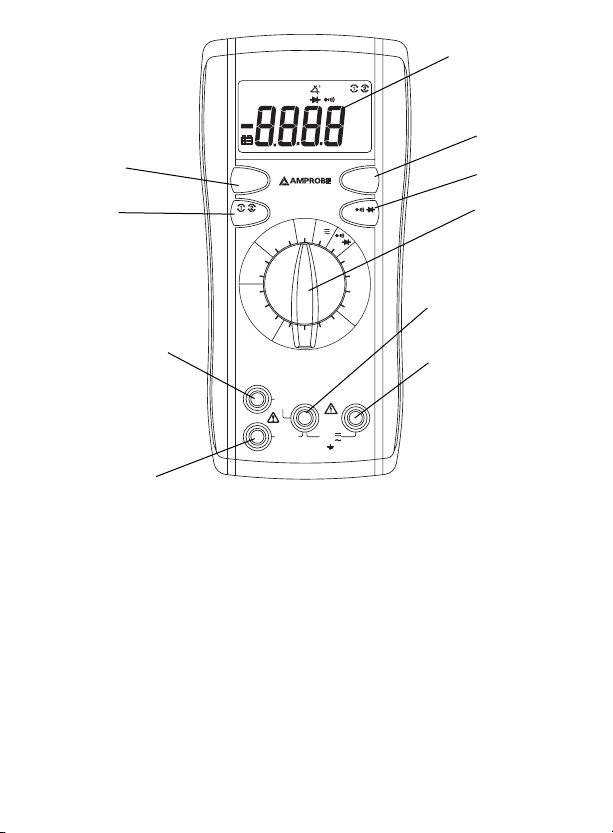
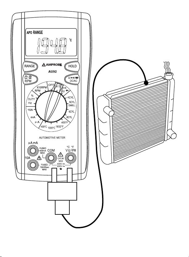
➓
➊
➋
➌
➒
➑
➐
➊ 4 Digit LCD with Function Indicators
Data Hold Button
➋
Resistance / Continuity / Diode / AC/DC Button
➌
Function / Range / Selector Knob
➍
COM Input
➎
Temperature / Volts / Ohms / RPM / Dwell Input
➏
10 Amp Input
➐
uA, mA Input
➑
RPM Button
➒
Range Lock Button
➓
2
➍
➎
➏
Page 5

AU92 Automotive Multimeter
Contents
Symbols ............................................................................................................................................... 4
Introduction ....................................................................................................................................... 4
Warnings and Precautions ................................................................................................................ 5
Unpacking and Inspection ................................................................................................................ 6
Measuring Procedures ....................................................................................................................... 3
Maintenance ..................................................................................................................................... 10
Troubleshooting ................................................................................................................... 10
Battery Replacement ............................................................................................................ 10
General Specications ..................................................................................................................... 11
3
Page 6

SYMBOLS
Introduction
The AU92 is a digital meter for automotive applications that measure both AC and DC
voltage, AC and DC current, Resistance, Continuity, Diode Test Dwell, RPM, % Duty Cycle,
and Temperature.
Caution ! Refer to the explanation in this Manual
Caution ! Risk of electric shock
Earth (Ground)
Double Insulation or Reinforced insulation
AC--Alternating Current
DC--Direct Current
Conforms to relevant Australian standards
Underwriters Laboratories Inc. [Note: Canadian and US.]
Complies with European Directives
Do not dispose of this product as unsorted municipal waste
4
Page 7

WARNINGS AND PRECAUTIONS
Safety Information
• The AU92 Automotive Meter conforms to EN61010-1:2001; CAT III 600 V, class 2 and
pollution deg.2
• This instrument is EN61010-1 certified for Installation Category III ( 600V). It is recommended for use in distribution level and fixed installations, as well as lesser installations, and not for primary supply lines, overhead lines and cable systems.
• Do not exceed the maximum overload limits per function (see specifications) nor the
limits marked on the instrument itself. Never apply more than 600 Vdc/600 V ac rms
between the test lead and earth ground.
• The extension probe tip TP92 is intended for use only with TL36 test leads. The TP92
is CAT III-1000V / CAT IV-600V rated. Keep fingers behind the guard ring.
WARNING
• Before and after hazardous voltage measurements, test the voltage function on a
known source such as line voltage to determine proper meter functioning.
• Disconnect the test leads from the test points before changing meter functions.
• Inspect the Clampmeter, test leads and accessories before every use. Do not use any
damaged part.
• Never ground yourself when taking measurements. Do not touch exposed circuit elements or test probe tips.
• Do not operate the instrument in an explosive atmosphere.
• To reduce the risk of fire or electric shock, do not expose this product to rain or
moisture.
• The meter is intended only for indoor use. To avoid electrical shock hazard, observe
the proper safety precautions when working with voltages above 60 VDC or 30 VAC
rms. These voltage levels pose a potential shock hazard to the user.
• Before and after hazardous voltage measurements, test the voltage function on a
known source such as line voltage to determine proper meter functioning.
• Keep your hands/fingers behind the hand/finger barriers (of the meter and the test
leads) that indicate the limits of safe access of the hand-held part during measurement.
• Inspect test leads, connectors, and probes for damaged insulation or exposed metal
before using the instrument. If any defects are found, replace them immediately.
• Exercise extreme caution when: measuring voltage >20 V // current >10 mA // AC
power line with inductive loads // AC power line during electrical storms // current,
when the fuse blows in a circuit with open circuit voltage >600 V // servicing CRT
equipment.
• Remove test leads before opening the case to change the battery.
5
Page 8

• Disconnect circuit power and discharge all high-voltage capacitors before testing
resistance, continuity, diodes, or capacitance.
• To avoid false readings, which could lead to possible electric shock or personal
injury, replace the batteries as soon as the low battery indicator (
Unpacking and Inspection
Your shipping carton should include:
AU92 Digital meter
Inductive pick-up probe
Test lead set (one black, one red)
Test lead extender tip (threaded - one black, one red)
Alligator clips (threaded - one black, one red)
Temperature Adapter (TA-1A)
Temperature Sensor (TP-255A)
Spare fuse ( 500 mA) FP520
One 9V battery
Carrying case
Users Manual
If any of the items are damaged or missing, return the complete package to the place of
purchase for an exchange.
) appears.
6
Page 9

OPERATION
Before taking any measurements, read the Safety Information Section. Always examine
the instrument for damage, contamination (excessive dirt, grease, etc.) and defects.
Examine the test leads for cracked or frayed insulation. If any abnormal conditions exist
do not attempt to make any measurements.
Function
modes. Selects DC or AC current modes.
Auto Power Off
1. Auto power off: approx. 10 minutes.
2. After auto power off, press any button to restart the meter, and the reading of
measurement will be maintained in the display.
Disable Auto Power Off Feature:
Press and hold the (RANGE) button while rotating function switch from off to any
position to turn the meter on. The auto power off feature is disabled. Note “APO”
annunciator is turned off on the LCD.
Data Hold Button
Press [HOLD] button to lock the reading on display, and release it by pressing the button
again.
Range Button
The meter also has a manual range mode. In manual range, you select and lock the meter
in a range. To manually select a range: Press [RANGE] button to hold the selected range.
Subsequently pressing the [RANGE] button will select each range in sequence from the
lowest to highest range. Hold the button for 2 seconds to return to the Autorange Mode.
If magnitude is unknown, set meter to highest range and reduce range until a
satisfactory reading is obtained.
Functions that show RANGE when rst selecting indicate Range measurement is locked.
Anytime display shows RANGE, this is indication the meter is locked in that range.
Button: Selects ohm/continuity and diode modes. Selects DC or AC volts
7
Page 10

RPM ➊ ➋ Button: In the RPM function the meter defaults to RPM ➋ for conventional
4-Cycle engines. Press the RPM button to toggle to RPM ➊ for 2-Cycle engines or waste
spark (DIS) 4-Cycle engines.
RPM Measurements (fig. 1)
1. Set the Function/Range switch to the desired RPM range.
2. Connect the red inductive pick-up to the “VΩ” jack and the black inductive pick-up
to the “COM” jack.
3. Connect the inductive pick-up to a spark plug wire. If no reading is received, unhook
the clamp, turn it over and connect again.
4. Press the RPM button to toggle between RPM ➊ for 2-Cycle engines or Distributorless
Ignition System (DIS) or RPM ➋ for 4-Cycle engines.
Dwell (fig. 2)
1. Set the Function/Range switch to the desired Dwell range.
2 Connect the red test lead to the “VΩ" jack and the black test lead to the "COM" jack.
3. Connect red lead to coil “-“ and black lead to ground
Voltage Measurements (see fig. 3)
1. Set the Function/Range knob to Voltage V
DC voltage
2. Connect the test leads to the device or circuit being measured.
3. For DC, a (-) sign is displayed for negative polarity; positive polarity is implied.
Current Measurements (see fig. 4)
1. Set the Function knob to uA, mA, 10A. Use the function button to select AC or DC
current.
2. Connect the red test lead to the (uA, mA or 10A) jack and the black test lead to the
“COM” jack.
3. Remove power from the circuit under test and open the normal circuit path where
the measurement is to be taken. Connect the meter in series with the circuit.
4. Apply power and read the value from the display.
. Use the Function button to select AC or
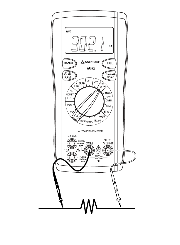
Resistance Measurements (see fig. 5)
1. Set the Function knob to the Ω
2. Connect the red test lead to the “VΩ" jack and the black test lead to the "COM" jack.
3. Remove power from the equipment under test.
4. Connect the test leads to the points of measurements and read the value from the
display.
. Use Function button to select ohms Ω.
8
Page 11

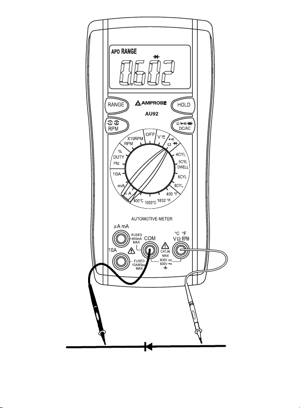
Diode Tests (see fig. 6)
1. Set the Function knob to the " Ω
2. Connect the red test lead to the “VΩ" jack and the black test lead to the "COM"
3. Turn off power to the circuit under test. External voltage across the components
4. Touch probes to the diode. A forward-voltage drop is about 0.6V (typical for a sili-
5. Reverse probes. If the diode is good, "OL" is displayed. If the diode is shorted,
6. If the diode is open, "OL" is displayed in both directions.
7. Audible Indication: Less than 0.25 Ω.
Continuity Measurements (see fig. 7)
1. Set the Function knob to the " Ω
2. Connect the red test lead to the “VΩ" jack and the black test lead to the “COM”
3. Turn off power to the circuit under test. External Voltage across the components
4. Connect the test leads to the two points at which continuity is to be tested. The
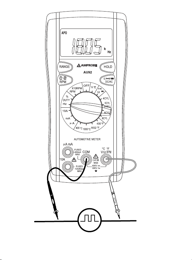
Frequency and Duty Cycle Measurements (see fig. 8)
1. Set the Function knob to the “Hz“ or “%” position.
2. Connect the red test lead to the “VΩ" jack and the black test lead to the “COM”
3. Connect the test leads to the point of measurement and read the frequency or duty
Temperature Measurements (see fig. 9)
1. Set the Function knob to the desired temperature range: °C, °F.
2. Connect the K-type thermocouple to the TEMP adapter and plug into VΩ and COM.
3. Match the polarity of the adapter to the polarity of the thermocouple.
4. Connect the TEMP adapter to the VΩ and COM jacks.
test.
diode
jack.
causes invalid readings.
con diode).
"0.00" or another number is displayed.
jack.
causes invalid reading.
buzzer will sound if the resistance is less than approximately 25Ω.
jack.
cycle from the display.
" position. Use the Function button to select
" position. Set Function button to “ “.
9
Page 12

MAINTENANCE
WARNING
Remove test leads before changing battery or fuse or performing any servicing.
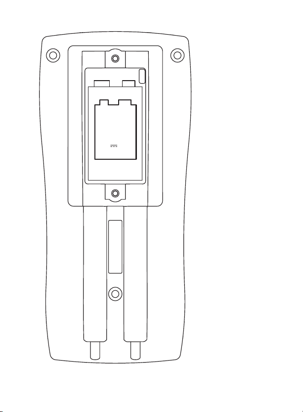
Battery Replacement (see fig. 10)
Power is supplied by a 9 volt battery. (NEDA 1604, IEC 6F22). The “
LCD display when replacement is needed. To replace the battery, remove the three screws
from the back of the meter and lift off the front case. Remove the battery from case
bottom.
Trouble Shooting
If the instrument fails to operate correctly, check battery, fuses and test leads etc., and
replace as necessary.
Refer to the LIMITED WARRANTY section for obtaining warranty or repairing service.
Cleaning and Storage
Periodically wipe the case with a damp cloth and mild detergent; do not use abrasives
or solvents. If the meter is not to be used for periods of longer than 60 days, remove the
battery and store separately.
Fuse Replacement
If no current measurements are possible, check for a blown overload protection fuse. For
access to fuses, remove the three screws from the back of the meter and lift off the front
case. Replace F1 only with the original type 0.5A / 500V (FP520), fast acting ceramic fuse,
Replace F2 only with the original type 10A / 500V (FP540), fast acting ceramic fuse .
“ appears on the
10
Page 13

GENERAL SPECIFICATIONS
Display: 3¾ digit liquid crystal display (LCD) with a maximum reading of 3999.
Polarity: Automatic, positive implied, negative polarity indication.
Overrange: (OL) or (-OL) is displayed.
Zero: Automatic.
Low battery indication: The “
“ is displayed when the battery voltage drops below
the operating level.
Measurement rate: 2 times per second, nominal.
Auto power off: Approx. 10 minutes.
Operating environment: 0°C to 50°C at < 70% RH.
Storage temperature: -20°C to 60°C at < 80% RH.
Accuracy: Stated accuracy at 23°C ± 5°C, <75% RH.
Temperature Coefficient: 0.1 × (specied accuracy) per °C. (0°C to 18°C, 28°C to 50°C).
Altitude: 2000m, indoor operation
Power: Standard 9-volt battery, NEDA 1604, JIS 006P, IEC 6F22.
Battery life: 150 hours typical with carbon zinc.
Dimensions: 165 × 78 × 50 mm ( 6.5 x 3.1 x 1.9 in.)
Weight: Approx. 315g (11.1 oz). including holster.
Accessories: One pair test leads, temperature adapter, inductive pick-up probe,
type-K thermocouple, One spare fuse (0.5A/500V), 9V battery (installed) and users
manual.
Safety : Meets IEC61010-1 2
nd
Ed., UL61010-1 2nd Ed. CAT III-600 Volts AC & DC; Class II;
Pollution degree: 2; EN61010-2-032
EMC: Conforms to EN61326-1.
This product complies with requirements of the following European Community
Directives: 89/ 336/ EEC (Electromagnetic Compatibility) and 73/ 23/ EEC (Low Voltage)
as amended by 93/ 68/ EEC (CE Marking). However, electrical noise or intense
electromagnetic elds in the vicinity of the equipment may disturb the measurement
circuit. Measuring instruments will also respond to unwanted signals that may be
present within the measurement circuit. Users should exercise care and take appropriate
precautions to avoid misleading results when making measurements in the presence of
electronic interference.
11
Page 14

ELECTRICAL SPECIFICATION Accuracy at 23 °C ± 5 °C, < 75% R.H.
DC VOLTS
Ranges: 400 mV, 4 V, 40 V, 400 V, 600 V
Accuracy: ±(1.0% rdg + 2 dgts)
Resolution: 0.1 mV
Input impedance: 400 mV: >100 MΩ; 4 V:10 MΩ; 40 V ~ 600 V: 9.1 MΩ
Overload protection: 600VDC or AC rms
AC VOLTS
Ranges: 400 mV, 4 V, 40 V, 400 V, 600 V
Range: Accuracy:
400 mV (50 ~ 100 Hz) ±(2.0% rdg + 5 dgts)
4, 40, 400, 600 V (50 ~ 500 Hz) ±(2.0% rdg + 5 dgts)
Resolution: 0.1 mV
Input impedance: 400 mV: >100 MΩ; 4 V: 10 MΩ; 40 V ~ 600 V: 9.1 MΩ
Overload protection: 600 VDC or AC rms
DC CURRENT
Ranges: 400 µA, 4000 µA, 40 mA, 400 mA, 10 A
Range: Accuracy:
400 µA to 400 mA ranges ±(2.0% rdg + 2 dgts)
10 A range ±(3.0% rdg + 3 dgts)
10A input: 10 A for 60 seconds maximum followed by a 10 minutes cooling period
Resolution: 0.1 µA
Voltage burden: 0.2 V on 400uA, 40mA ranges ;
2V on 4000 uA, 400 mA ranges
Input protection: 0.5 A / 500V fast blow ceramic fuse (FP520)
10 A / 500 V fast blow ceramic fuse (FP540)
AC CURRENT
Ranges: 400 uA, 4000 uA, 40 mA, 400 mA, 10 A
Range: (50 ~ 500 Hz) Accuracy:
400 uA to 400 mA ranges ±(2.5% rdg + 5 dgts)
10 A range ±(3.5% rdg + 5 dgts)
10A input: 10 A for 60 seconds maximum followed by a 10 minutes cooling period
Voltage burden: see DC Current
Input protection: see DC Current
12
Page 15

RESISTANCE
Ranges: 400 Ω, 4 kΩ, 40 kΩ, 400 kΩ, 4 MΩ, 40 MΩ
Resolution: 0.1 Ω on 400 Ω range
Range: Accuracy:
400 Ω to 400 kΩ ranges ±(1.5% rdg + 4 dgts)
4 MΩ range ±(2.5% rdg + 4 dgts)
40 MΩ range ±(5.0% rdg + 5 dgts)
Open circuit volts: -0.45Vdc (-1.2Vdc on 400 Ω range)
Overload protection: 600 VDC or AC RMS
FREQUENCY (Hz) (Auto ranging)
Range: 4 kHz, 40 kHz, 400 kHz
Resolution: 1Hz
Accuracy: ±(0.1% rdg + 3 dgts)
Sensitivity: 10Hz ~ 400kHz: > 3.5Vrms
Minimum pulse width: > 2.5us
Duty cycle limits: >30% and < 70%
Overload protection: 600 VDC or AC RMS
TEMPERATURE
Ranges: -20°C ~ 1000°C, -4°F ~ 1832°F
Resolution: 0.1°C, 0.1°F
Accuracy: 10°C ~ 200°C ±(1.0% rdg + 3°C)
-20°C ~ 10°C ±(2.0% rdg + 4°C)
200°C ~ 1000°C ±(3.0% rdg + 2°C)
-4°F ~ 50°F ±(2.0% rdg + 8°F)
50°F ~ 400°F ±(1.0% rdg + 6°F)
400°F ~ 1832°F ±(3.0% rdg + 4°F)
Sensor type: K-type thermocouple
Overload protection: 600 VDC or AC RMS
RPM
Range: RPM 600 ~ 4000 RPM
X10 RPM 4000 ~ 12000 RPM
Resolution: 1 RPM
Accuracy: ±(2% rdg + 4 dgts)
Effect Reading: > 600 RPM
Overload protection: 600 VDC or AC RMS
13
Page 16

% DUTY CYCLE
Range: 1.0% ~ 90.0%
Resolution: 0.1%
Pulse width: > 100us, < 100ms
Accuracy: ±(2% rdg + 5 dgts)
Overload protection: 600 VDC or AC RMS
DWELL ANGLE
No. OF Cylinders: 4, 5, 6, 8
Range: 4 CYL 0 ~ 90.0°
5 CYL 0 ~ 72.0°
6 CYL 0 ~ 60.0°
8 CYL 0 ~ 45.0°
Resolution: 0.1°
Accuracy: ±(2% rdg + 5 dgts)
Overload protection: 600 VDC or AC RMS
CONTINUITY
Audible indication: Less than 25Ω
Response time: 500ms
Overload protection: 600VDC or AC RMS
DIODE TEST
Test current: 1.0mA (approximate)
Accuracy: ±(3.0% rdg + 3 dgts)
Resolution: 10mV
Audible indication: <0.25V
Open circuit volts: 3.0VDC typical
Overload protection: 600VDC or AC RMS
14
Page 17

RPM
Figure 1
15
Page 18

Dwell
Figure 2
16
Page 19

Black Red
Voltage
Figure 3
17
Page 20

Red Black
Current
X
Figure 4
18
Page 21
Black Red
Resistance
Figure 5
19
Page 22
Black Red
Diode
Figure 6
20
Page 23

Black Red
Continuity
Figure 7
21
Page 24
Black Red
Frequency
Duty Cycle
Figure 8
22
Page 25
- +
Temperature
+
-
Figure 9
23
Page 26
SIZE:
NEDA 1604
JIS 006P
IEC 6F22
9V
Battery
Replacement
Figure 10
24
Page 27

AU92
Multimètre automobile
Français
Page 28

Limites de garantie et de responsabilité
Amprobe garantit l’absence de vices de matériaux et de fabrication de ce produit dans des
conditions normales d’utilisation et d’entretien pendant une période d’un an prenant effet à la
date d’achat. Cette garantie ne s’applique pas aux fusibles, aux piles jetables ni à tout produit
mal utilisé, modifié, contaminé, négligé ou endommagé par accident ou soumis à des conditions
anormales d’utilisation et de manipulation. Les revendeurs n’ont pas l’autorisation de prolonger
toute autre garantie au nom d’Amprobe. Pour bénéficier de la garantie, renvoyez le produit
accompagné d’un justificatif d’achat auprès d’un centre de services agréé par Amprobe Test
Tools, d’un distributeur ou d’un revendeur Amprobe. Voir la section Réparation pour tous les
détails. LA PRESENTE GARANTIE EST LE SEUL ET EXCLUSIF RECOURS DE L’UTILISATEUR TOUTES
AUTRES GARANTIES, EXPLICITES, IMPLICITES OU STATUTAIRES, NOTAMMENT LES GARANTIES
DE QUALITE MARCHANDE OU D’ADAPTATION A UN OBJECTIF PARTICULIER SONT EXCLUES PAR
LES PRESENTES. LE FABRICANT NE SERA EN AUCUN CAS TENU RESPONSABLE DE DOMMAGES
PARTICULIERS, INDIRECTS, ACCIDENTELS OU CONSECUTIFS, NI D’AUCUNS DEGATS OU PERTES DE
DONNEES, SUR UNE BASE CONTRACTUELLE, EXTRA-CONTRACTUELLE OU AUTRE. Etant donné
que certaines juridictions n’admettent pas les limitations d’une condition de garantie implicite
ou l’exclusion ou la limitation de dégâts accidentels ou consécutifs, il se peut que les limitations
et les exclusions de cette garantie ne s’appliquent pas à votre cas.
Réparation
Tous les outils de test renvoyés pour un étalonnage ou une réparation couverte ou non par la
garantie doivent être accompagnés des éléments suivants : nom, raison sociale, adresse, numéro
de téléphone et justificatif d’achat. Ajoutez également une brève description du problème ou
du service demandé et incluez les cordons de test avec l’appareil. Les frais de remplacement
ou de réparation hors garantie doivent être acquittés par chèque, mandat, carte de crédit avec
date d’expiration, ou par bon de commande payable à l’ordre d’Amprobe® Test Tools.
Remplacements et réparations sous garantie – Tous pays
Veuillez lire la déclaration de garantie et vérifiez la pile avant de demander une réparation.
Pendant la période de garantie, tout outil de test défectueux peut être renvoyé auprès de
votre distributeur Amprobe® Test Tools pour être échangé contre un produit identique ou
similaire. Consultez la section « Where to Buy » sur le site www.amprobe.com pour obtenir la
liste des distributeurs dans votre région. Au Canada et aux Etats-Unis, les appareils devant être
remplacés ou réparés sous garantie peuvent également être envoyés dans un centre de services
Amprobe® Test Tools (voir les adresses ci-dessous).
Remplacements et réparations hors garantie – Canada et Etats-Unis
Les appareils à réparer hors garantie au Canada et aux Etats-Unis doivent être envoyés
dans un centre de services Amprobe
vous auprès de votre lieu d’achat pour connaître les tarifs en vigueur de remplacement ou
de réparation.
Aux Etats-Unis Au Canada
Amprobe Test Tools Amprobe Test Tools
Everett, WA 98203 Mississauga, ON L4Z 1X9
Tel: 877-AMPROBE (267-7623) Tel: 905-890-7600
Remplacements et réparations hors garantie – Europe
Les appareils européens non couverts par la garantie peuvent être remplacés par votre
distributeur Amprobe® Test Tools pour une somme nominale. Consultez la section « Where to
Buy » sur le site www.amprobe.com pour obtenir la liste des distributeurs dans votre région.
European Correspondence Address*
Amprobe
In den Engematten 14
79286 Glottertal, Germania
Tel.: +49 (0) 7684 8009 - 0
*(Réservée à la correspondance – Aucune réparation ou remplacement n’est possible à cette
adresse. Nos clients européens doivent contacter leur distributeur.)
®
Test Tools Europe
®
Test Tools. Appelez Amprobe® Test Tools ou renseignez-
1
Page 29

RPM
DC/AC
Ω
/ /
COM
10A
μ
A mA
RANGE
HOLD
Hz
Mk
Ω
AC
DC
RANGE
APO
HOLD
mVA
μ
RPM
X10RPM
%
400
1000
1832
DUTY
10A
Hz
mA
6CYL
8CYL
400
A
5CYL
OFF
V
X10RPM
RPM
Ω
4CYL
μ
DWELL
%
CAT.III
MAX
600V
600V
MAX
FUSED
MAX
FUSED
400mA
10A/60sec
AUTOMOTIVE METER
AU92
℉
℉
℃
℃
℃
RPM
VΩ
℃ ℉
℉
➓
➊
➋
➌
➒
➎
➑
➐
➊ Ecran LCD à 4 chiffres avec indicateurs de fonction
Bouton de maintien d’affichage
➋
Bouton de résistance / continuité / diode / c.a./c.c.
➌
Sélecteur de gamme / fonction
➍
Entrée COM
➎
Entrée de température / volts / ohms / RPM / Angle de came
➏
Entrée 10 A
➐
Entrée uA, mA
➑
Bouton RPM
➒
Verrouillage de gamme
➓
2
➏
➍
Page 30

AU92 Automotive Multimeter
Table des matières
Symboles ............................................................................................................................................. 4
Introduction ....................................................................................................................................... 4
Mises en garde et précautions .......................................................................................................... 5
Déballage et inspection ..................................................................................................................... 6
Techniques de mesure ........................................................................................................................ 3
Entretien ........................................................................................................................................... 10
Dépannage ............................................................................................................................ 10
Changement des piles ........................................................................................................... 10
Caractéristiques générales .............................................................................................................. 11
3
Page 31

SYMBOLES
Introduction
Destiné aux applications automobiles, l’AU92 est un multimètre numérique qui mesure
les tensions alternatives et continues, les courants alternatifs et continus, la résistance, la
continuité, l’angle de fermeture du test de diode, les RPM, le rapport cyclique en % et la
température.
Attention ! Se reporter aux explications de ce manuel
Attention ! Risque de décharge électrique
Prise de terre
Double isolation ou isolation renforcée
c.a. -- courant alternatif
c.c. -- courant continu
Conforme aux directives de l’association australienne de normalisation
Underwriters Laboratories, Inc. [Remarque : norme canadienne
et américaine.]
Conforme aux directives européennes
Ne pas mettre ce produit au rebut avec les déchets ménagers non triés
4
Page 32

AVERTISSEMENTS ET PRECAUTIONS
Consignes de sécurité
• Le multimètre automobile AU92 est conforme à EN61010-1:2001; CAT III 600 V,
classe 2 et degré de pollution 2.
• Cet appareil est certifié conforme à la norme EN61010-1 pour les installations de
catégorie III (600 V). Il est recommandé pour les installations fixes et les équipements
au niveau distribution, ainsi que pour les installations de catégories inférieures, mais
il n’est pas destiné aux lignes du réseau d’alimentation électrique principale, aux
lignes aériennes ou aux systèmes câblés.
• Ne pas dépasser les limites de surcharge maximum par fonction (voir les caractéristiques techniques) ou les limites indiquées sur l’appareil lui-même. Ne jamais
appliquer plus de 600 V c.c. / 600 V c.a. eff. entre le cordon de mesure et la prise
de terre.
• L’embout de rallonge de sonde TP92 est réservé aux cordons de mesure TL36.
L’embout TP92 est homologué CAT III-1000V / CAT IV-600V. Garder les doigts derrière la collerette de protection.
AVERTISSEMENT
• Avant et après les mesures de tensions dangereuses, tester la fonction de tension sur
une source connue, une tension secteur p. ex., pour déterminer le bon fonctionnement du multimètre.
• Débrancher les cordons de mesure des points de test avant de changer de fonction
sur le multimètre.
• Inspecter la pince ampèremétrique, les cordons de mesure et les accessoires avant
toute utilisation. Ne pas utiliser de pièce endommagée.
• Ne jamais se relier à la terre en prenant des mesures. Ne toucher ni aux éléments de
circuit exposés ni aux pointes des sondes de test.
• Ne pas utiliser l’appareil dans une atmosphère explosive.
• Pour réduire le risque d’incendie ou d’électrocution, ne pas exposer cet appareil à
l’humidité ou à la pluie.
• Le multimètre est destiné à être utilisé à l’intérieur uniquement. Pour éviter les chocs
électriques, observer les précautions de sécurité appropriées en intervenant sur des
tensions supérieures à 60 V c.c. ou à 30 V c.a. eff. Ces niveaux de tension présentent
un risque d’électrocution pour l’utilisateur.
• Avant et après les mesures de tensions dangereuses, tester la fonction de tension sur
une source connue, une tension secteur p. ex., pour déterminer le bon fonctionnement du multimètre.
• Garder les mains/doigts derrière les collerettes de protection qui indiquent les limites
de sécurité du multimètre et des cordons pendant la mesure.
• Inspecter les cordons de mesure, les connecteurs et les sondes pour détecter
l’endommagement de l’isolant ou les parties métalliques exposées avant d’utiliser
l’instrument. Remplacer immédiatement l’élément si des défauts sont détectés.
• Faire preuve d’extrême prudence en : mesurant une tension > 20 V // un courant
5
Page 33

> 10 mA // les lignes d’alimentation secteur avec charges inductives // les lignes
d’alimentation secteur pendant les orages électriques // un courant alors que le
fusible a sauté dans un circuit avec une tension en circuit ouvert > 600 V // lors d’une
intervention sur un appareil à écran cathodique.
• Retirer les cordons de mesure avant d’ouvrir le boîtier pour changer les piles.
• Débrancher l’alimentation du circuit et décharger tous les condensateurs à tension
élevée avant de contrôler la résistance, la continuité, les diodes ou la capacité.
• Pour éviter les mesures erronées qui posent des risques d’électrocution ou de blessure, remplacez les piles dès que l’indicateur d’état de piles faibles apparaît (
Déballage et inspection
Le carton d’emballage doit inclure les éléments suivants :
Multimètre numérique AU92
Sonde à prise de mesure inductive
Jeu de cordons de mesure (un noir, un rouge)
Pointe de rallonge de cordon de mesure (leté un noir, un rouge)
Pinces crocodiles (letées, une noire, une rouge)
Adaptateur de température (TA-1A)
Capteur de température (TP-255A)
Fusible de rechange (500 mA) FP520
Une pile 9 V
Sacoche de transport
Mode d’emploi
Si l’un de ces éléments est endommagé ou manquant, renvoyez le contenu complet de
l’emballage au lieu d’achat pour l’échanger.
).
6
Page 34

FONCTIONNEMENT
Lire la section Consignes de sécurité avant de relever des mesures. Toujours rechercher les
traces d’endommagement, de contamination (impuretés, graisse, etc.) et les défauts sur
l’appareil. Constater l’absence de ssures ou d’isolant efloché sur les cordons de mesure.
Ne tenter aucune mesure en présence de conditions anormales.
Bouton de fonction
de diode. Sélectionne les modes de mesure en volts c.c. ou c.a. Sélectionne les modes de
mesure en courant c.c. ou c.a.
Arrêt automatique
1. Arrêt automatique : environ 10 minutes.
2. Après l’arrêt automatique, appuyez sur un bouton pour redémarrer le multimètre :
le résultat de la mesure relevée est maintenu sur l’affichage.
Désactiver la fonction d’arrêt automatique :
Maintenez la touche [RANGE] enfoncée tout en déplaçant le sélecteur de fonction de la
position OFF pour activer le multimètre. La fonction d’arrêt automatique est désactivée.
L’indicateur « APO » est éteint sur l’écran LCD.
Bouton de maintien d’affichage
Appuyez sur la touche [HOLD] pour verrouiller le résultat afché et relâchez-le en
appuyant une deuxième fois.
Bouton de gamme
Le multimètre possède aussi un mode de gamme manuelle. En gamme manuelle,
sélectionnez et verrouillez le multimètre dans une gamme. Pour sélectionner
manuellement la gamme : Appuyez sur [RANGE] pour maintenir la gamme sélectionnée.
La pression consécutive du bouton [RANGE] sélectionne chaque gamme, de la plus basse
à la plus haute. Maintenez la touche enfoncée pendant 2 secondes pour revenir en mode
de gamme automatique.
Si l’amplitude est inconnue, réglez le multimètre sur la gamme la plus élevée, puis
réduisez-la an d’obtenir une valeur satisfaisante.
Les fonctions afchent RANGE à la première sélection pour indiquer le verrouillage de la
mesure dans une gamme. Quand l’afchage indique RANGE, le multimètre est verrouillé
dans cette gamme.
: Sélectionne les modes de mesure de résistance/continuité et
7
Page 35

Bouton RPM ➊ ➋ : Dans la fonction RPM, le multimètre sélectionne par défaut RPM ➋
pour les moteurs traditionnels à 4 temps. Appuyez sur RPM pour basculer RPM ➊
sur les moteurs à 2 temps ou sur les moteurs à 4 temps à système d’allumage (DIS) à
étincelle perdue.
Mesures RPM (voir fig. 1)
1. Réglez le sélecteur de fonction/gamme sur la gamme RPM souhaitée.
2. Reliez le fil de mesure inductive rouge à la prise « VΩ » et le fil de mesure inductive
noir à la prise « COM ».
3. Branchez la sonde inductive à un fil de bougie. Si aucun résultat n’est obtenu,
détachez la pince, inversez-la et rebranchez-la.
4. Appuyez sur la touche RPM pour basculer entre RPM ➊ sur les moteurs à 2 temps ou
sur les systèmes d’allumage sans distribution (DIS) et RPM ➋ sur les moteurs à 4 temps.
Angle de came (voir fig. 2)
1. Réglez le sélecteur de fonction/gamme sur la gamme de fermeture souhaitée.
2 Reliez le cordon de mesure rouge à la prise « VΩ » et le cordon de mesure noir à la
prise « COM ».
3. Reliez le cordon rouge à la bobine « - » et le cordon noir à la terre.
Mesures de tension (voir fig. 3)
1. Réglez le sélecteur de gamme/fonction sur Voltage V
tion pour sélectionner une tension alternative ou continue AC ou DC.
2. Reliez les cordons de mesure à l’appareil ou au circuit mesuré.
3. Pour le courant continu, un signe (-) indique une polarité négative ; une polarité positive est impliquée.
Mesures de courant (voir fig. 4)
1. Réglez le sélecteur de fonction sur uA, mA, 10A. Utilisez la touche de fonction pour
sélectionner un courant c.a. ou c.c.
2. Reliez le cordon de mesure rouge à la prise (uA, mA ou 10A) et le cordon de mesure
noir à la prise « COM ».
3. Coupez l’alimentation du circuit testé et ouvrez le trajet normal du circuit à l’endroit
où la mesure doit être prise. Branchez le multimètre en série avec le circuit.
4. Mettez sous tension et relevez la valeur affichée.
. Utilisez le sélecteur de fonc-
Mesures de résistance (voir fig. 5)
1. Réglez le sélecteur de fonction sur Ω
sélectionner la résistance Ω.
2. Reliez le cordon de mesure rouge à la prise « VΩ » et le cordon de mesure noir à la
prise « COM ».
3. Coupez l’alimentation de l’équipement testé.
. Utilisez le sélecteur de fonction pour
8
Page 36

4. Reliez les cordons de mesure aux points de mesure et relevez la valeur affichée.
Contrôles de diode (voir fig. 6)
1. Réglez le sélecteur de fonction sur la position « Ω
ction pour sélectionner le contrôle de diode
2. Reliez le cordon de mesure rouge à la prise « VΩ » et le cordon de mesure noir à la
prise « COM ».
3. Mettez le circuit testé hors tension. La présence d’une tension externe aux bornes
des composants entraîne des mesures erronées.
4. Touchez la diode avec les sondes. Une baisse de tension directe est d’environ 0,6 V
(typique pour une diode au silicium).
5. Inversez les sondes. Si la diode est bonne, « OL » apparaît. Si la diode est en
court-circuit, « 0,00 » ou un autre chiffre est affiché.
6. Si la diode est ouverte, « OL » apparaît dans les deux sens.
7. Indication sonore : inférieur à 0,25 Ω.
Mesures de continuité (voir fig. 7)
1. Réglez le sélecteur de fonction sur la position « Ω
fonction sur «
2. Reliez le cordon de mesure rouge à la prise « VΩ » et le cordon de mesure noir à la
prise « COM ».
3. Mettez le circuit testé hors tension. La tension externe aux bornes des composants
entraîne une mesure erronée.
4. Connectez les cordons de mesure aux deux points auxquels la continuité est mesurée. L’avertisseur retentit si la résistance est inférieure à environ 25 Ω.
Mesures de fréquence et de rapport cyclique (voir fig. 8)
1. Réglez le sélecteur de fonction sur la position « Hz » ou « % ».
2. Reliez le cordon de mesure rouge à la prise « VΩ » et le cordon de mesure noir à la
prise « COM ».
3. Connectez les cordons de mesure au point de mesure et relevez la fréquence ou le
rapport cyclique affiché.
».
. » Utilisez la touche de fon-
.
. » Réglez le sélecteur de
Mesures de température (voir fig. 9)
1. Réglez le sélecteur de fonction sur la gamme de température souhaitée: °C, °F.
2. Reliez le thermocouple de type K à l’adaptateur TEMP et branchez-le dans VΩ et
dans COM.
3. Alignez la polarité de l’adaptateur sur celle du thermocouple.
4. Reliez l’adaptateur TEMP aux prises VΩ et COM.
9
Page 37

ENTRETIEN
AVERTISSEMENT
Retirez les cordons de mesure avant de changer la pile ou le fusible ou d’effectuer une
intervention.
Changement des piles (voir fig. 10)
L’alimentation est fournie par une pile de 9 volts. (NEDA 1604, CEI 6F22). Le symbole
» apparaît sur l’écran LCD quand la pile doit être remplacée. Pour remplacer la pile,
«
retirez les trois vis du boîtier dorsal et soulevez la face avant. Retirez la pile au fond
du boîtier.
Dépannage
Si l’appareil ne fonctionne pas correctement, vériez la pile, les fusibles et les cordons de
mesure, etc. et remplacez si nécessaire.
Consultez la section GARANTIE LIMITEE pour obtenir des renseignements sur la garantie
et le service après-vente.
Nettoyage et entreposage
Nettoyez régulièrement le boîtier avec un chiffon humide et du détergent doux.
N’utilisez ni abrasifs, ni solvants. Si le multimètre doit rester inutilisé pendant plus de
60 jours, retirez la pile et rangez-la séparément.
Changement de fusible
Si aucune mesure de courant n’est possible, vériez l’état des fusibles de protection
contre les surcharges. Pour accéder aux fusibles, retirez les trois vis du boîtier dorsal et
soulevez la face avant. Ne remplacez F1 qu’avec un fusible céramique rapide d’origine de
0,5 A / 500 V (FP520), ne remplacez F2 qu’avec un fusible céramique rapide d’origine de
10 A / 500 V (FP540).
10
Page 38

CARACTERISTIQUES GENERALES
Affichage : Afcheur à cristaux liquides (LCD), 3¾ chiffres de résolution et 3999 mesures
maximum.
Polarité : Indication de la polarité négative, à implication positive, automatique.
Dépassement de gamme : (OL) ou (-OL) s’afche.
Zéro : Automatique.
Témoin de pile faible : Le symbole «
» apparaît lorsque la tension de pile passe en
dessous du niveau d’exploitation.
Vitesse de mesure : 2 fois par seconde, nominal.
Arrêt automatique : environ 10 minutes.
Environnement de fonctionnement : de 0 °C à 50 °C à < 70 % HR.
Température d’entreposage : de -20 °C à 60 °C à < 80 % HR.
Précision : Précision déclarée à 23 °C ± 5 °C, < 75 % HR.
Coefficient thermique : 0,1 x (précision spéciée) par °C. (0 °C à 18 °C, 28 °C à 50 °C).
Altitude : 2000 m, à l’intérieur de locaux
Alimentation : Pile standard de 9 volts, NEDA 1604, JIS 006P, CEI 6F22.
Durée de vie de pile : 150 heures en moyenne pour la pile au carbone-zinc.
Dimensions : 165 x 78 x 50 mm (6,5 x 3,1 x 1,9 po)
Poids : environ 315 g (11,1 oz) étui inclus.
Accessoires : Une paire de cordons de mesure, un adaptateur de température, une sonde
à prise de mesure inductive, un thermocouple de type K, un fusible de rechange (0,5 A /
500 V), une pile 9 V (installée) et un mode d’emploi.
Sécurité : Conforme à CEI61010-1 2
e
édition UL61010-1 2e édition CAT III 600 volts c.a.
et c.c. ; classe II ; degré de pollution : 2 ; EN61010-2-032
EMC: Conforme à EN61326-1.
Ce produit est conforme aux exigences des directives suivantes de la Communauté
européenne : 89/ 336/ CEE (Compatibilité électromagnétique) et 73/ 23/ CEE (Basse
tension) modiée par 93/ 68/ CEE (Marquage CE). Toutefois, le bruit électrique ou les
champs électromagnétiques intenses à proximité de l’équipement sont susceptibles de
perturber le circuit de mesure. Les appareils de mesure réagissent également aux signaux
indésirables parfois présents dans le circuit de mesure. Les utilisateurs doivent faire
preuve de prudence et prendre les mesures nécessaires pour éviter les erreurs de mesure
en présence de parasites électromagnétiques.
11
Page 39

CARACTERISTIQUES ELECTRIQUES Précision à 23 °C ± 5 °C, < 75 % H.R.
VOLTS C.C.
Gammes : 400 mV, 4 V, 40 V, 400 V, 600 V
Précision : ± (1,0 % de lecture + 2 chiffres)
Résolution : 0,1 mV
Impédance d’entrée : 400 mV : > 100 MΩ ; 4 V : 10 MΩ ; 40 V à 600 V : 9,1 MΩ
Protection contre les surcharges : 600 Vc.c. ou c.a. eff.
Volts c.a.
Gammes : 400 mV, 4 V, 40 V, 400 V, 600 V
Gamme : Précision :
400 mV (50 à 100 Hz) ± (2,0 % de lecture + 5 chiffres)
4, 40, 400, 600 V (50 à 500 Hz) ± (2,0 % de lecture + 5 chiffres)
Résolution : 0,1 mV
Impédance d’entrée : 400 mV : > 100 MΩ ; 4 V : 10 MΩ ; 40 V à 600 V : 9,1 MΩ
Protection contre les surcharges : 600 V c.c. ou c.a. eff.
COURANT C.C.
Gammes : 400 µA, 4000 µA, 40 mA, 400 mA, 10 A
Gamme : Précision :
Gammes 400 µA à 400 mA : ± (2,0 % de lecture + 2 chiffres)
Gamme 10 A ± (3,0 % de lecture + 3 chiffres)
Entrée 10 A : 10 A pendant un délai de 60 secondes maximum suivi d’une période de
refroidissement de 10 minutes
Résolution : 0,1 µA
Tension de charge : 0,2 V sur les gammes 400 uA, 40 mA
2 V sur les gammes 4000 uA, 400 mA
Protection d’entrée : Fusible céramique rapide de 0,5 A / 500 V (FP520)
Fusible céramique rapide de 10 A / 500 V (FP540)
Courant alternatif
Gammes : 400 uA, 4000 uA, 40 mA, 400 mA, 10 A
Gamme : (50 à 500 Hz) Précision :
Gammes 400 uA à 400 mA ± (2,5 % de lecture + 5 chiffres)
Gamme 10 A ± (3,5 % de lecture + 5 chiffres)
Entrée 10 A : 10 A pendant un délai de 60 secondes maximum suivi d’une période de
refroidissement de 10 minutes
Tension de charge : voir Courant c.c.
Protection d’entrée : voir Courant c.c.
12
Page 40

RESISTANCE
Gammes : 400 Ω, 4 kΩ, 40 kΩ, 400 kΩ, 4 MΩ, 40 MΩ
Résolution : 0,1 Ω sur la gamme 400 Ω
Gamme : Précision :
Gammes 400 Ω à 400 kΩ ± (1,5 % de lecture + 4 chiffres)
Gamme 4 MΩ ± (2,5 % de lecture + 4 chiffres)
Gamme 40 M Ω ± (5,0 % de lecture + 5 chiffres)
Volts en circuit ouvert : -0,45 V c.c. (-1,2 V c.c. sur la gamme 400 Ω)
Protection contre les surcharges : 600 V c.c. ou c.a. eff.
FREQUENCE (Hz) (Gamme automatique)
Gamme : 4 kHz, 40 kHz, 400 kHz
Résolution : 1 Hz
Précision : ± (0,1 % de lecture + 3 chiffres)
Sensibilité : 10 Hz à 400 kHz : > 3,5 V eff.
Largeur d’impulsion minimum : > 2,5 us
Limites du rapport cyclique : > 30 % et < 70 %
Protection contre les surcharges : 600 V c.c. ou c.a. eff.
TEMPERATURE
Gammes : -20 °C à 1000 °C, -4 °F à 1832 °F
Résolution : 0,1 ºC ; 0,1 ºF
Précision : 10 °C ~ 200 °C ± (1,0 % de lecture + 3 °C)
-20 °C ~ 10 °C ± (2.0 % de lecture + 4 °C)
-20 °C ~ 1000 °C ± (3,0 % de lecture + 2 °C)
-4 °F ~ 50 °F ± (2,0 % de lecture - 8 °F)
50 °F ~ 400 °F ± (1,0 % de lecture - 6 °F)
400 °F ~ 1832 °F ± (3,0 % de lecture - 4 °F)
Type de capteur : Thermocouple de type K
Protection contre les surcharges : 600 V c.c. ou c.a. eff.
RPM
Gamme : RPM 600 à 4000 RPM
X10 RPM 4000 ~ 12000 RPM
Résolution : 1 RPM
Précision : ± (2 % de lecture + 4 chiffres)
Mesure de l’effet : 600 RPM
Protection contre les surcharges : 600 V c.c. ou c.a. eff.
13
Page 41

% DE RAPPORT CYCLIQUE
Gamme : 1,0 % ~ 90,0 %
Résolution : 0,1 %
Largeur d’impulsion : > 100 us, < 100 ms
Précision : ± (2 % de lecture + 5 chiffres)
Protection contre les surcharges : 600 V c.c. ou c.a. eff.
ANGLE DE CAME
Nb de cylindres : 4, 5, 6, 8
Gamme : 4 CYL 0 ~ 90,0°
5 CYL 0 ~ 72,0°
6 CYL 0 ~ 60,0°
8 CYL 0 ~ 45,0°
Résolution : 0,1°
Précision : ± (2 % de lecture + 5 chiffres)
Protection contre les surcharges : 600 V c.c. ou c.a. eff.
CONTINUITE
Indication sonore : inférieur à 25 Ω
Temps de réponse : 500 ms
Protection contre les surcharges : 600 V c.c. ou c.a. eff.
TEST DE DIODE
Courant de test : 1,0 mA (approximatif)
Précision : ± (3,0 % de lecture + 3 chiffres)
Résolution : 10 mV
Indication sonore : < 0,25 V
Volts en circuit ouvert : 3,0 V c.c. typique
Protection contre les surcharges : 600 V c.c. ou c.a. eff.
14
Page 42

RPM
Figure 1
15
Page 43

ROUGE
CONTACTS DE RUPTEUR
NOIR
CONDENSATEUR
BOBINE
PILE
CIRCUIT ET CONTACT
D’ALLUMAGE
Angle de came
Figure 2
16
Page 44

Noir Rouge
Tension
Figure 3
17
Page 45

Rouge Noir
Courant
X
Figure 4
18
Page 46

Noir Rouge
Résistance
Figure 5
19
Page 47

Noir Rouge
Diode
Figure 6
20
Page 48

Noir Rouge
Continuité
Figure 7
21
Page 49

Noir Rouge
Fréquence
Rapport
cyclique
Figure 8
22
Page 50

- +
Température
+
-
Figure 9
23
Page 51

SIZE:
NEDA 1604
JIS 006P
IEC 6F22
9V
Changement
des piles
Figure 10
24
Page 52

AU92
Kfz-Multimeter
Deutsch
Page 53

Beschränkte Gewährleistung und Haftungsbeschränkung
Es wird gewährleistet, dass dieses Amprobe-Produkt für die Dauer von einem Jahr ab dem
Kaufdatum frei von Material- und Fertigungsdefekten ist. Diese Gewährleistung erstreckt sich
nicht auf Sicherungen, Einwegbatterien oder Schäden durch Unfälle, Nachlässigkeit, Missbrauch,
Änderungen oder abnormale Betriebsbedingungen bzw. unsachgemäße Handhabung. Die
Verkaufsstellen sind nicht dazu berechtigt, diese Gewährleistung im Namen von Amprobe zu
erweitern. Um während der Gewährleistungsperiode Serviceleistungen in Anspruch zu nehmen, das Produkt mit Kaufnachweis an ein autorisiertes Amprobe Test Tools Service-Center
oder an einen Amprobe-Fachhändler/-Distributor einsenden. Nähere Einzelheiten siehe
Abschnitt „Reparatur“. DIESE GEWÄHRLEISTUNG STELLT DEN EINZIGEN UND ALLEINIGEN
RECHTSANSPRUCH AUF SCHADENERSATZ DAR. ALLE ANDEREN (VERTRAGLICH GEREGELTEN ODER
GESETZLICH VORGESCHRIEBENEN) GEWÄHRLEISTUNGEN, EINSCHLIESSLICH DER GESETZLICHEN
GEWÄHRLEISTUNG DER MARKTFÄHIGKEIT UND DER EIGNUNG FÜR EINEN BESTIMMTEN
ZWECK, WERDEN ABGELEHNT. DER HERSTELLER ÜBERNIMMT KEINE HAFTUNG FÜR SPEZIELLE,
INDIREKTE, NEBEN- ODER FOLGESCHÄDEN ODER FÜR VERLUSTE, DIE AUF BELIEBIGER URSACHE
ODER RECHTSTHEORIE BERUHEN. Weil einige Staaten oder Länder den Ausschluss oder die
Einschränkung einer implizierten Gewährleistung sowie den Ausschluss von Begleit- oder Folgeschäden nicht zulassen, ist diese Gewährleistungsbeschränkung möglicherweise für Sie nicht gültig.
Reparatur
Allen Geräten, die innerhalb oder außerhalb des Garantiezeitraums zur Reparatur oder
Kalibrierung eingesendet werden, müssen mit folgenden Informationen und Dokumenten
versehen werden: Name des Kunden, Firmenname, Adresse, Telefonnummer und Kaufbeleg.
Zusätzlich bitte eine kurze Beschreibung des Problems oder der gewünschten Wartung sowie
die Messleitungen dem Messgerät beilegen. Die Gebühren für außerhalb des Garantiezeitraums
durchgeführteReparaturen oder für den Ersatz von Instrumenten müssen per Scheck,
Zahlunganweisung oder Kreditkarte (Kreditkartennummer mit Ablaufdatum) beglichen werden
oder es muss ein Auftrag auf Rechnung an Amprobe
Reparaturen und Ersatz während des Garantiezeitraums - alle Länder
Bitte die Garantieerklärung lesen und die Batterie prüfen, bevor Reparaturen angefordert
werden. Während der Garantieperiode können alle defekten Geräte zum Umtausch gegen
dasselbe oder ein ähnliches Produkt an den Amprobe
Ein Verzeichnis der zuständigen Distributoren ist im Abschnitt „Where to Buy“ (Verkaufsstellen)
auf der Website www.amprobe.com zu finden. Darüber hinaus können in den USA und in
Kanada Geräte an ein Amprobe® Test Tools Service-Center (siehe Adresse unten) zur Reparatur
oder zum Umtausch eingesendet werden.
Reparaturen und Ersatz außerhalb des Garantiezeitraums - USA und Kanada
Für Reparaturen außerhalb des Garantiezeitraums in den Vereinigten Staaten und in Kanada
werden die Geräte an ein Amprobe® Test Tools Service-Center gesendet. Auskunft über die
derzeit geltenden Reparatur- und Austauschgebühren erhalten Sie von Amprobe® Test Tools
oder der Verkaufsstelle.
In den USA In Kanada
Amprobe Test Tools Amprobe Test Tools
Everett, WA 98203 Mississauga, ON L4Z 1X9
Tel.: 877-AMPROBE (267-7623) Tel.: 905-890-7600
Reparaturen und Austausch außerhalb des Garantiezeitraums - Europa
Geräte mit abgelaufener Garantie können durch den zuständigen Amprobe® Test ToolsDistributor gegen eine Gebühr ersetzt werden. Ein Verzeichnis der zuständigen Distributoren ist
im Abschnitt „Where to Buy“ (Verkaufsstellen) auf der Website www.amprobe.com zu finden.
Korrespondenzanschrift für Europa*
Amprobe
In den Engematten 14
79286 Glottertal, Germany
Tel.: +49 (0) 7684 8009 - 0
*(Nur Korrespondenz – keine Reparaturen und kein Umtausch unter dieser Anschrift. Kunden in
Europa wenden sich an den zuständigen Distributor.)
®
Test Tools Europe
®
Test Tools formuliert werden.
®
Test Tools-Distributor gesendet werden.
1
Page 54

RPM
DC/AC
Ω
/ /
COM
10A
μ
A mA
RANGE
HOLD
Hz
Mk
Ω
AC
DC
RANGE
APO
HOLD
mVA
μ
RPM
X10RPM
%
400
1000
1832
DUTY
10A
Hz
mA
6CYL
8CYL
400
A
5CYL
OFF
V
X10RPM
RPM
Ω
4CYL
μ
DWELL
%
CAT.III
MAX
600V
600V
MAX
FUSED
MAX
FUSED
400mA
10A/60sec
AUTOMOTIVE METER
AU92
℉
℉
℃
℃
℃
RPM
VΩ
℃ ℉
℉
➓
➊
➋
➌
➒
➑
➊ 4 Stellen LCD mit Funktionsanzeige
➐
HOLD-Taste (Datenhaltemodus)
➋
Widerstand- / Kontinuität- / Dioden- und AC/DC-Taste
➌
Funktion- / Bereichsauswahl-Drehschalter
➍
COM-Eingang
➎
Temperatur- / Volt- / Ohm- / Drehzahl- / Schließwinkel-Eingang
➏
10-Ampere-Eingang
➐
uA-, mA-Eingang
➑
RPM-Taste (Drehzahl)
➒
➓
RANGE-Taste (Bereichsfixierung)
➍
➎
➏
2
Page 55

AU92 Automotive Multimeter
Inhalt
Symbole .............................................................................................................................................. 4
Einleitung ........................................................................................................................................... 4
Warn- und Vorsichtshinweise ............................................................................................................ 5
Auspacken und Überprüfen .............................................................................................................. 6
Messverfahren .................................................................................................................................... 3
Wartung ............................................................................................................................................ 10
Fehlerbehebung .................................................................................................................... 10
Ersetzen der Batterie ............................................................................................................. 10
Allgemeine Spezikationen ............................................................................................................ 11
3
Page 56

SYMBOLE
Einleitung
Das AU92 ist ein digitales Messgerät für Kfz-Anwendungen und misst Wechsel- und
Gleichspannung, Wechsel- und Gleichstromstärke, Widerstand, Kontinuität, Dioden,
Schließwinkel, RPM, %-Tastgrad und Temperatur.
Vorsicht! Siehe Erklärung in diesem Handbuch
Vorsicht! Stromschlaggefahr
Erde, Masse
Schutzisolierung oder verstärkte Isolierung
Wechselstrom (AC - Alternating Current)
Gleichstrom (DC - Direct Current)
Übereinstimmung mit den relevanten australischen Normen
Underwriters Laboratories Inc. [Hinweis: Kanada und USA]
Übereinstimmung mit EU-Vorschriften
Dieses Produkt nicht im unsortierten Kommunalabfall entsorgen.
4
Page 57

Warnungen und Sicherheitshinweise
Sicherheitsinformationen
• Das AU92 Kfz-Messgerät stimmt mit EN61010-1:2001, CAT III 600 V, Klasse 2 und
Verschmutzungsgrad 2 überein.
• Dieses Messgerät ist EN61010-1-zertifiziert für Installationskategorie III (600 V).
Es wird zum Gebrauch auf Verteilungsebene und in Festinstallationen sowie
auch in untergeordneten Installationen empfohlen, nicht jedoch für primäre
Stromverteilung, Hochspannungsleitungen und Kabelsysteme.
• Die maximalen Überlastungsgrenzen der einzelnen Funktionen (siehe technische
Daten) und die auf dem Instrument markierten Grenzwerte nicht überschreiten.
Zwischen Messleitung und Masse niemals mehr als 600 V Gleichspannung oder 600 V
Wechselspannung eff. anlegen.
• Die Verlängerungs-Sondenspitze TP92 ist nur zur Verwendung mit TL36 Prüfkabeln
vorgesehen. Die TP92-Spitze stimmt mit CAT III-1000V / CAT IV-600V überein. Finger
hinter dem Schutzring halten.
ACHTUNG
• Vor und nach gefährlichen Spannungsmessungen die Spannungsfunktion an einer
bekannten Quelle, z. B. Netzspannung, testen, um die Funktionstüchtigkeit des
Messgeräts zu prüfen.
• Die Messleitungen vor dem Wechseln von Messgerätfunktionen von den
Prüfpunkten trennen.
• Vor jedem Gebrauch das Zangenmessgerät, die Messleitungen und das Zubehör prüfen. Keine beschädigten Teile verwenden.
• Sich selbst isolieren, wenn Messungen durchgeführt werden. Keine freiliegenden
Schaltungselemente oder Prüfspitzen/Messleitungen berühren.
• Das Messgerät nicht in Umgebungen mit explosiven Gasen betreiben.
• Um das Risiko von Feuer und Stromschlag zu verringern, dieses Produkt nicht Regen
oder Feuchtigkeit aussetzen.
• Das Messgerät ist ausschließlich für Gebrauch in Gebäuden konzipiert. Zur
Vermeidung von Stromschlaggefahr bei Arbeiten mit Spannungen oberhalb 60 V
Gleichspannung bzw. 30 V Wechselspannung eff. die ordnungsgemäßen Sicherheitsvorkehrungen einhalten. Diese Spannungen stellen eine Stromschlaggefahr für den
Bediener dar.
• Vor und nach gefährlichen Spannungsmessungen die Spannungsfunktion an einer
bekannten Quelle, z. B. Netzspannung, testen, um die Funktionsfähigkeit des
Messgeräts zu prüfen.
• Die Hände/Finger stets hinter dem Hand-/Fingerschutz (des Messgeräts und der
Messleitungen) halten, der die Grenzen sicherer Berührung des handgehaltenen
Teils während Messungen angibt.
• Vor jedem Gebrauch die Messleitungen, Anschlüsse und Sonden bezüglich beschädigter Isolierung und exponiertem Metall untersuchen. Falls ein Defekt festgestellt
wird, das entsprechende Teil unverzüglich ersetzen.
5
Page 58

• In den folgenden Situationen besonders vorsichtig vorgehen: Messung von
Spannung > 20 V // Stromstärke > 10 mA // Wechselspannungsleitungen mit
Induktivlasten // Wechselspannungsleitungen während Gewittern // Strom mit einer
durchgebrannten Sicherung in einem Schaltkreis mit Leerlaufspannung > 600 V // bei
der Wartung von Kathodenröhrengeräten.
• Vor dem Öffnen des Gehäuses zum Auswechseln der Batterie die Messleitungen
entfernen.
• Vor dem Prüfen von Widerstand, Kontinuität, Dioden oder Kapazität den Strom des
Stromkreises ausschalten und alle Hochspannungskondensatoren entladen.
• Zur Vermeidung falscher Ablesungen, die zu Stromschlag oder Verletzungen führen
können, die Batterie ersetzen, sobald das Symbol für schwache Batterie (
geblendet wird.
Auspacken und Überprüfen
Der Verpackungskarton sollte Folgendes enthalten:
AU92 Digitales Messgerät
Induktive Messsonde
Messleitungssatz (1 schwarz, 1 rot)
Messleitungsverlängerungsspitze (mit Gewinde - 1 schwarz, 1 rot)
Krokodilklemmen (mit Gewinde - 1 schwarz, 1 rot)
Temperaturadapter (TA-1A)
Temperatursensor (TP-255A)
Ersatzsicherung (500 mA) FP520
Eine (1) 9-V-Batterie
Tragbehälter
Bedienungshandbuch
Wenn einer dieser Artikel beschädigt ist oder fehlt, die gesamte Lieferung zwecks Ersatz
an die Verkaufsstelle zurücksenden.
) ein-
6
Page 59

BEDIENUNG
Vor der Durchführung von Messungen den Abschnitt „Sicherheitsinformationen“
durchlesen. Das Messgerät stets auf Beschädigung, Verunreinigung (übermäßiger
Schmutz, Fett usw.) und Defekte untersuchen. Die Messleitungen auf rissige oder
anderweitig beschädigte Isolierung untersuchen. Falls abnormale Umstände herrschen,
nicht versuchen, Messungen durchzuführen.
Funktionstaste
bzw. Wechselspannungsmodus aus. Wählt Gleich- bzw. Wechselstrommodus aus.
Automatische Abschaltung
1. Auto Power Off: ungefähr 10 Minuten.
2. Nach automatischer Ausschaltung eine beliebige Taste drücken, um das Messgerät
neu zu starten. Der Messwert bleibt auf der Anzeige erhalten.
Automatische Ausschaltfunktion (APO):
Die RANGE-Taste drücken und gedrückt halten und gleichzeitig den Funktionsschalter
von OFF in eine beliebige Position schalten Die automatische Ausschaltfunktion (APO) ist
deaktiviert. Das APO-Symbol auf der LCD wird ausgeblendet.
HOLD-Taste (Datenhaltemodus)
Die HOLD-Taste drücken, um den Messwert auf der Anzeige festzuhalten, und die Taste
erneut drücken, um den Wert wieder freizugeben.
RANGE-Taste
Das Messgerät verfügt auch über manuelle Bereichswahl. Bei manueller Bereichswahl
wird ein Bereich ausgewählt und das Messgerät wird in diesem Bereich xiert. Manuelles
Auswählen eines Bereichs: Die RANGE-Taste drücken, um den ausgewählten Bereich zu
halten. Wiederholtes Drücken der RANGE-Taste wählt jeden verfügbaren Bereich der
Reihe nach vom niedrigsten bis zum höchsten Bereich aus. Die Taste 2 Sekunden gedrückt
halten, um zur automatischen Bereichswahl zurückzukehren.
Falls die Größe unbekannt ist, das Messgerät auf den höchsten Bereich einstellen und
dann den Bereich reduzieren, bis ein zufriedenstellender Messwert erzielt wird.
Funktionen, die RANGE einblenden, wenn sie ausgewählt werden, geben an, dass die
RANGE-Messung xiert ist. Wenn immer RANGE angezeigt wird, gibt dies an, dass das
Messgerät in diesem Bereich xiert ist.
: Wählt Ohm/Kontinuitäts- und Dioden-Modus aus. Wählt Gleich-
7
Page 60

Taste RPM ➊ ➋ : In der RPM-Funktion schaltet das Messgerät standardmäßig auf RPM ➋
für herkömmliche 4-Takt-Motoren. Die RPM-Taste drücken, um auf RPM ➊ für 2-TaktMotoren oder Zündsystem-4-Takt-Motoren (DIS) zu schalten
RPM-Messung (siehe Abb. 1)
1. Den Funktions-/Bereichsschalter auf den gewünschten Drehzahlbereich einstellen.
2. Die rote induktive Messsonde an die Buchse VΩ und die schwarze induktive Messsonde
an die Buchse COM anschließen.
3. Die induktive Messsonde an ein Zündkerzenkabel anschließen. Wenn kein Messwert
erzielt wird, die Zange abnehmen, umkehren und wieder anlegen.
4. Die RPM-Taste drücken, um zwischen RPM ➊ für 2-Takt-Motoren und verteilerlose
Zündsysteme (DIS) und RPM ➋ für 4-Takt-Motoren umzuschalten.
Schließwinkel (siehe Abb. 2)
1. Den Funktions-/Bereichsschalter auf den gewünschten Schließwinkelbereich einstellen.
2 Die rote Messleitung an die Buchse VΩ und die schwarze Messleitung an die Buchse
COM anschließen.
3. Die rote Messleitung an Spule „-“ und die schwarze Messleitung an Erde anschließen.
Spannungsmessung (siehe Abb. 3)
1. Den Funktions-/Bereichsdrehschalter auf V
den, um Wechselspannung (AC) oder Gleichspannung (DC) auszuwählen.
2. Die Messleitungen an das zu messende Gerät bzw. den zu messenden Stromkreis
anschließen.
3. Für Gleichspannung (DC) wird ein Minuszeichen (-) für negative Polarität angezeigt.
Positive Polarität wird impliziert.
Stromstärkemessung (siehe Abb. 4)
1. Den Funktionsdrehschalter auf uA, mA oder 10A einstellen. Die Funktionstaste verwenden, um Wechselstrom (AC) oder Gleichstrom (DC) auszuwählen.
2. Die rote Messleitung an die Buchse uA, mA oder 10A und die schwarze Messleitung an
die Buchse COM anschließen.
3. Den Strom vom zu prüfenden Stromkreis entfernen und den normalen Strompfad an
der Stelle öffnen, an der die Messung erfolgen soll. Das Messgerät mit dem Stromkreis
in Reihe schalten.
4. Strom anlegen und den Wert von der Anzeige ablesen.
einstellen. Die Funktionstaste verwen-
Widerstandsmessung (siehe Abb. 5)
1. Den Funktionsdrehschalter auf Ω
Ohm Ω auszuwählen.
2. Die rote Messleitung an die Buchse VΩ und die schwarze Messleitung an die Buchse
COM anschließen.
3. Den Strom vom zu prüfenden Gerät trennen.
einstellen. Die Funktionstaste verwenden, um
8
Page 61

4. Die Messleitungen an die Messpunkte anschließen und den Wert von der Anzeige
ablesen.
Diodenprüfung (siehe Abb. 6)
1. Den Funktionsdrehschalter auf die Position Ω einstellen. Die Funktionstaste
verwenden, um Diodenprüfung auszuwählen
2. Die rote Messleitung an die Buchse VΩ und die schwarze Messleitung an die Buchse
COM anschließen.
3. Die Stromversorgung des zu prüfenden Stromkreises ausschalten. Externe Spannung
über den Komponenten verursacht ungültige Messwerte.
4. Mit den Sonden die Diode berühren. Ein Vorwärtsspannungsabfall beträgt ungefähr
0,6 V (typisch für eine Silikondiode).
5. Sonden umkehren. Wenn die Diode in Ordnung ist, wird OL angezeigt. Wenn die
Diode kurzgeschlossen ist, wird 0,00 oder eine andere Zahl angezeigt.
6. Wenn die Diode offen ist, wird OL in beiden Richtungen angezeigt.
7. Akustische Anzeige: Weniger als 0,25 Ω.
Kontinuitätsmessung (siehe Abb. 7)
1. Den Funktionsdrehschalter in die Position Ω
stellen.
2. Die rote Messleitung an die Buchse VΩ und die schwarze Messleitung an die Buchse
COM anschließen.
3. Die Stromversorgung des zu prüfenden Stromkreises ausschalten. Externe Spannung
über den Komponenten verursacht ungültige Messwerte.
4. Die Messleitungen an die zwei Punkte anschließen, an denen Kontinuität gemessen
werden soll. Der Summer ertönt, wenn der Widerstand kleiner als ungefähr 25 Ω ist.
Frequenz- und Tastgradmessung (siehe Abb. 8)
1. Den Funktionsdrehschalter auf die Position Hz oder % einstellen.
2. Die rote Messleitung an die Buchse VΩ und die schwarze Messleitung an die Buchse
COM anschließen.
3. Die Messleitungen an die Messpunkte anschließen und die Frequenz bzw. den
Tastgrad von der Anzeige ablesen.
.
stellen. Die Funktionstaste auf
Temperaturmessung (siehe Abb. 9)
1. Den Funktionsdrehschalter auf den gewünschten Temperaturbereich einstellen: °C, °F.
2. Das Thermoelement-Typ-K an den TEMP-Adapter und dann an VΩ und COM
anschließen.
3. Die Polarität des Adapters an die Polarität des Thermoelements anpassen.
4. Den TEMP-Adapter an die Buchsen VΩ und COM anschließen.
9
Page 62

WARTUNG
WARNUNG
Vor dem Ersetzen der Batterie oder Sicherung bzw. vor dem Durchführen von
Servicearbeiten die Messleitungen entfernen.
Batterie ersetzen (siehe Abb. 10)
Strom wird durch eine 9-Volt-Batterie geliefert. (NEDA 1604, IEC 6F22). „
auf der LCD-Anzeige, wenn die Batterien ausgewechselt werden müssen. Um die Batterie
zu ersetzen, die drei Schrauben von der Rückseite des Messgeräts entfernen und die
Rückseite von der Gehäusevorderseite abheben. Die Batterie aus dem Gehäuseunterteil
entfernen.
Fehlerbehebung
Wenn das Gerät nicht korrekt funktioniert, die Batterie, die Sicherungen und die
Messleitungen prüfen und ggf. ersetzen.
Für Garantieansprüche oder Reparaturservice siehe Abschnitt BESCHRÄNKTE
GEWÄHRLEISTUNG.
Reinigung und Aufbewahrung
Das Gehäuse von Zeit zu Zeit mit einem feuchten Tuch und mildem Reinigungsmittel
abwischen. Keine Scheuer- oder Lösungsmittel verwenden. Wenn das Messgerät
für 60 Tage oder länger nicht verwendet wird, die Batterie entfernen und getrennt
aufbewahren.
Sicherung ersetzen
Wenn keine Strommessungen möglich sind, prüfen, ob eine Überlastschutzsicherung
durchgebrannt ist. Um die Sicherungen zu ersetzen, die drei Schrauben von der
Rückseite des Messgeräts entfernen und die Rückseite von der Gehäusevorderseite
abheben. F1 ausschließlich mit dem ursprünglichen Typ 0,5 A / 500 V (FP520), inke
Keramiksicherung ersetzen. F2 ausschließlich mit dem ursprünglichen Typ 10 A / 500 V
(FP540), inke Keramiksicherung ersetzen.
“ erscheint
10
Page 63

ALLGEMEINE TECHNISCHE DATEN
Anzeige: Flüssigkristallanzeige (LCD) mit 3¾ Stellen, mit Maximalanzeige von 3999.
Polarität: Automatisch, positiv = Standard, negativ = Anzeiger.
Überlast: (OL) oder (-OL) wird angezeigt.
Null: Automatisch.
Anzeige für schwache Batterie: „
den Betriebswert abfällt.
Messintervall: 2 mal pro Sekunde, Nennwert.
Auto Power Off: Ungefähr 10 Minuten.
Betriebsbereich: 0 °C bis 50 °C bei < 70 % RH.
Lagertemperatur: -20 °C bis 60 °C bei < 80 % RH.
Genauigkeit: Nenngenauigkeit bei 23 °C ± 5 °C, < 75 % RH.
Temperaturkoeffizient: 0,1 x (spezizierte Genauigkeit) / °C. (0 °C bis 18 °C, 28 °C bis 50 °C).
Höhenlage: 2000 m, Innenverwendung
Speisung: Standard-9-V-Batterie, NEDA 1604, JIS 006P, IEC 6F22.
Battery life: 150 Stunden, typisch, mit Zink-Kohle.
Abmessungen: 165 x 78 x 50 mm
Gewicht: Ungefähr 315 g, einschließlich Holster.
Zubehör: 1 Paar Messleitungen, Temperaturadapter, induktive Messsonde,
Thermoelement-Typ-K, 1 Ersatzsicherung (0,5 A / 500 V), 9-V-Batterie (eingelegt),
Bedienungshandbuch.
“ wird angezeigt, wenn die Batteriespannung unter
Sicherheit : Erfüllt IEC61010-1 2. Ausgabe, UL61010-1 2. Ausgabe. CAT III-600 Volt AC
und DC; Klasse II; Verschmutzungsgrad: 2; EN61010-2-032
EMC (elektromagnetische Verträglichkeit): Stimmt überein mit EN61326-1.
Dieses Produkt erfüllt die Anforderungen der folgenden EU-Richtlinien:
89/ 336/ EEC (Elektromagnetische Verträglichkeit) und 73/ 23/ EEC (Niederspannung)
mit dem Zusatz 93/ 68/ EEC (CE-Kennzeichnung). Elektrisches Rauschen oder intensive
elektromagnetische Felder in der Nähe des Geräts können jedoch den Messschaltkreis
stören. Messinstrumente reagieren auch auf unerwünschte Impulse/Signale, die unter
Umständen im Messschaltkreis vorkommen. Die Benutzer müssen die nötige Sorgfalt
walten lassen und geeignete Vorkehrungen treffen, um irreführende Ergebnisse bei
Messungen bei Vorhandensein elektrischer Störeinüsse zu vermeiden.
11
Page 64

ELEKTRISCHE SPEZIFIKATION Genauigkeit bei 23 °C ± 5 °C, < 75 % RH
DC VOLT
Bereiche: 400 mV, 4 V, 40 V, 400 V, 600 V
Genauigkeit: ± (1,0 % Anzeige + 2 Stellen)
Auflösung: 0,1 mV
Eingangsimpedanz: 400 mV: >100 MΩ; 4 V: 10 MΩ; 40 V ~ 600 V: 9,1 MΩ
Überlastschutz: 600 V DC oder AC eff.
AC VOLT
Bereiche: 400 mV, 4 V, 40 V, 400 V, 600 V
Bereich: Genauigkeit:
400 mV (50 ~ 100 Hz) ± (2,0 % Anzeige + 5 Stellen)
4, 40, 400, 600 V (50 ~ 500 Hz) ± (2,0 % Anzeige + 5 Stellen)
Auflösung: 0,1 mV
Eingangsimpedanz: 400 mV: > 100 MΩ; 4 V: 10 MΩ; 40 V ~ 600 V: 9,1 MΩ
Überlastschutz: 600 V DC oder AC eff.
GLEICHSTROM (DC - DIRECT CURRENT)
Bereiche: 400 µA, 4000 µA, 40 mA, 400 mA, 10 A
Bereich: Genauigkeit:
400 µA bis 400 mA Bereiche ± (2,0 % Anzeige + 2 Stellen)
10 A Bereich ± (3,0 % Anzeige + 3 Stellen)
10A Eingang: 10 A für 60 Sekunden maximal, gefolgt von einer 10 Minuten
Abkühlperiode
Auflösung: 0,1 µA
Spannungsbürde: 0,2 V auf 400 uA, 40 mA Bereichen;
2 V auf 4000 uA, 400 mA Bereichen
Eingangsschutz: 0,5 A / 500 V, flinke Keramiksicherung (FP520)
10 A / 500 V, flinke Keramiksicherung (FP540)
WECHSELSTROM
Bereiche: 400 µA, 4000 µA, 40 mA, 400 mA, 10 A
Bereich: (50 ~ 500 Hz) Genauigkeit:
400 uA bis 400 mA Bereiche ± (2,5 % Anzeige + 5 Stellen)
10 A Bereich ± (3,5 % Anzeige + 5 Stellen)
10A Eingang: 10 A für 60 Sekunden maximal, gefolgt von einer 10 Minuten
Abkühlperiode
Spannungsbürde: siehe DC Strom
Eingangsschutz: siehe DC Strom
12
Page 65

WIDERSTAND
Bereiche: 400 Ω, 4 kΩ, 40 kΩ, 400 kΩ, 4 MΩ, 40 MΩ
Auflösung: 0,1 Ω auf 400 Ω Bereich
Bereich: Genauigkeit:
400 Ω bis 400 kΩ Bereiche ± (1,5 % Anzeige + 4 Stellen)
4 MΩ Bereich ± (2,5 % Anzeige + 4 Stellen)
40 MΩ Bereich ± (5,0 % Anzeige + 5 Stellen)
Spannung in unterbrochenen
Schaltkreisen: -0,45 V DC (-1,2 V DC auf 400 Ω Bereich)
Überlastschutz: 600 V DC oder AC eff.
FREQUENZ (Hz) (automatische Bereichswahl)
Bereich: 4 kHz, 40 kHz, 400 kHz
Auflösung: 1 Hz
Genauigkeit: ± (0,1 % Anzeige + 3 Stellen)
Frequenzempfindlichkeit: 10 Hz ~ 400 kHz: > 3,5 V eff.
Mindest-Impulsbreite: > 2,5 us
Arbeitszykluslimits: > 30 % und < 70 %
Überlastschutz: 600 V DC oder AC eff.
TEMPERATUR
Bereiche: -20 °C ~ 1000 °C, -4 °F ~ 1832 °F
Auflösung: 0,1 °C, 0,1 °F
Genauigkeit: 10 °C ~ 200 °C ± (1,0 % Anzeige + 3 °C)
-20 °C ~ 10 °C ± (2,0 % Anzeige + 4 °C)
200 °C ~ 1000 °C ± (3,0 % Anzeige + 2 °C)
-4 °F ~ 50 °F ± (2,0 % Anzeige + 8 °F)
50 °F ~ 400 °F ± (1,0 % Anzeige + 6 °F)
400 °F ~ 1832 °F ± (3,0 % Anzeige + 4 °F)
Sensortyp: K-Thermoelement
Überlastschutz: 600 V DC oder AC eff.
RPM
Bereich: RPM 600 ~ 4000 RPM
X10 RPM 4000 ~ 12000 RPM
Auflösung: 1 RPM
Genauigkeit: ± (2 % Anzeige + 4 Stellen)
Wirkung: > 600 RPM
Überlastschutz: 600 V DC oder AC eff.
13
Page 66

% TASTGRAD
Bereich: 1,0 % ~ 90,0 %
Auflösung: 0,1 %
Impulsbreite: > 100 us, < 100 ms
Genauigkeit: ± (2 % Anzeige + 5 Stellen)
Überlastschutz: 600 V DC oder AC eff.
SCHLIESSWINKEL
Anzahl Zylinder 4, 5, 6, 8
Bereich: 4 ZYL 0 ~ 90,0°
5 ZYL 0 ~ 72,0°
6 ZYL 0 ~ 60,0°
8 ZYL 0 ~ 45,0°
Auflösung: 0,1°
Genauigkeit: ± (2 % Anzeige + 5 Stellen)
Überlastschutz: 600 V DC oder AC eff.
KONTINUITÄT
Akustische Anzeige: Weniger als 25 Ω
Ansprechzeit: 500 ms
Überlastschutz: 600 V DC oder AC eff.
DIODENPRÜFUNG
Prüfstrom: 1,0 mA (ungefähr)
Genauigkeit: ± (3,0 % Anzeige + 3 Stellen)
Auflösung: 10 mV
Akustische Anzeige: < 0,25 V
Spannung in unterbrochenen
Schaltkreisen: 3,0 V DC typisch
Überlastschutz: 600 V DC oder AC eff.
14
Page 67

RPM
Abbildung 1
15
Page 68

ROT
UNTERBRECHERKONTAKTBAUGRUPPE
SCHWARZ
KONDENSATOR
SPULE
BATTERIE
ZÜNDSCHALTER
UND STROMKREIS
Schließwinkel
Abbildung 2
16
Page 69

Schwarz Rot
Spannung
Abbildung 3
17
Page 70

Rot Schwarz
Stromstärke
X
Abbildung 4
18
Page 71

Schwarz Rot
Widerstand
Abbildung 5
19
Page 72

Schwarz Rot
Diode
Abbildung 6
20
Page 73

Schwarz Rot
Kontinuität
Abbildung 7
21
Page 74

Schwarz Rot
Frequenz-
tastgrad
Abbildung 8
22
Page 75

- +
Temperatur
+
-
Abbildung 9
23
Page 76

SIZE:
NEDA 1604
JIS 006P
IEC 6F22
9V
Ersetzen der
Batterie
Abbildung 10
24
Page 77

AU92
Multimetro per
applicazioni automobilistiche
Italiano
Page 78

Garanzia limitata e limitazione di responsabilità
Questo prodotto Amprobe sarà esente da difetti di materiale e fabbricazione per un anno a
decorrere dalla data di acquisto. Sono esclusi da questa garanzia i fusibili, le pile monouso e i
danni causati da incidenti, negligenza, uso improprio, alterazione, contaminazione o
condizioni anomale di funzionamento o maneggiamento. I rivenditori non sono autorizzati
a offrire nessun’altra garanzia a nome della Amprobe. Per richiedere un intervento durante
il periodo di garanzia, restituire il prodotto, allegando la ricevuta di acquisto, a un centro di
assistenza autorizzato Amprobe Test Tools oppure a un rivenditore o distributore Amprobe
locale. Per ulteriori informazioni vedere la sezione Riparazioni. QUESTA GARANZIA È IL SOLO
RICORSO A DISPOSIZIONE DELL’ACQUIRENTE E SOSTITUISCE QUALSIASI ALTRA GARANZIA,
ESPRESSA, IMPLICITA O PREVISTA DALLA LEGGE, COMPRESA, MA NON A TITOLO ESCLUSIVO,
QUALSIASI GARANZIA IMPLICITA DI COMMERCIABILITÀ O DI IDONEITÀ PER SCOPI PARTICOLARI.
IL PRODUTTORE NON SARÀ RESPONSABILE DI DANNI O PERDITE SPECIALI, INDIRETTI O
ACCIDENTALI, DERIVANTI DA QUALSIASI CAUSA O TEORIA. Poiché in alcuni Paesi non sono
permesse esclusioni o limitazioni di una garanzia implicita o dei danni incidentali o indiretti,
questa limitazione di responsabilità potrebbe non riguardare l’acquirente.
Riparazioni
A tutti gli strumenti di misura restituiti per interventi in garanzia o non coperti dalla
garanzia, oppure per la taratura, devono essere allegate le seguenti informazioni: il proprio
nome e quello dell’azienda, indirizzo, numero telefonico e ricevuta di acquisto. Allegare anche
una breve descrizione del problema o dell’intervento richiesto e i cavi di misura. Gli importi
dovuti per sostituzioni o riparazioni non coperte dalla garanzia vanno versati tramite assegno,
vaglia bancario, carta di credito con data di scadenza, oppure ordine di acquisto all’ordine di
®
Amprobe
Test Tools.
Sostituzioni e riparazioni in garanzia – Tutti i Paesi
Leggere la garanzia e controllare le pile prima di richiedere una riparazione. Durante il
periodo di garanzia, si può restituire uno strumento difettoso al rivenditore Amprobe
Tools per ricevere un prodotto identico o analogo. Nella sezione “Where to Buy” del sito
www.metermantesttools.com c’è un elenco dei distributori più vicini. Negli Stati Uniti e nel
Canada gli strumenti da sostituire o riparare in garanzia possono essere inviati anche a un
centro di assistenza Amprobe® Test Tools, agli indirizzi seguenti.
Sostituzioni e riparazioni non coperte dalla garanzia – U.S.A. e Canada
Se la riparazione non è coperta dalla garanzia negli Stati Uniti e nel Canada, lo strumento va
inviato a un centro di assistenza Amprobe
rivenditore per informazioni sui costi delle riparazioni e sostituzioni.
Negli Stati Uniti Nel Canada
Amprobe Test Tools Amprobe Test Tools
Everett, WA 98203 Mississauga, ON L4Z 1X9
Tel.: 877-AMPROBE (267-7623) Tel.: 905-890-7600
Sostituzioni e riparazioni non coperte dalla garanzia – Europa
Gli strumenti acquistati in Europa e non coperti dalla garanzia possono essere sostituiti dal
rivenditore Amprobe® Test Tools per un importo nominale. Nella sezione “Where to Buy” del
sito www.metermantesttools.com c’è un elenco dei distributori più vicini.
Recapito postale europeo*
Amprobe
In den Engematten 14
79286 Glottertal, Germania
Tel.: +49 (0) 7684 8009 - 0
*(Solo per corrispondenza; non rivolgersi a questo indirizzo per riparazioni o sostituzioni. Si
pregano i clienti europei di rivolgersi al proprio rivenditore.)
®
Test Tools Europe
®
Test Tools. Rivolgersi alla Amprobe® Test Tools o al
®
Test
1
Page 79

RPM
DC/AC
Ω
/ /
COM
10A
μ
A mA
RANGE
HOLD
Hz
Mk
Ω
AC
DC
RANGE
APO
HOLD
mVA
μ
RPM
X10RPM
%
400
1000
1832
DUTY
10A
Hz
mA
6CYL
8CYL
400
A
5CYL
OFF
V
X10RPM
RPM
Ω
4CYL
μ
DWELL
%
CAT.III
MAX
600V
600V
MAX
FUSED
MAX
FUSED
400mA
10A/60sec
AUTOMOTIVE METER
AU92
℉
℉
℃
℃
℃
RPM
VΩ
℃ ℉
℉
➓
➊
➋
➌
➒
➎
➑
➐
Display a cristalli liquidi a 4 cifre con indicatori di funzione
➊
Pulsante Data Hold
➋
Pulsante di selezione Resistenza / Continuità / Diodi / AC/DC
➌
Selettore di funzione / portata
➍
Ingresso COM
➎
Ingresso Temperatura / Volt / Ohm / RPM / Angolo di chiusura
➏
Ingresso 10 A
➐
Ingresso uA, mA
➑
Pulsante RPM
➒
Pulsante bloccaggio portata
➓
2
➏
➍
Page 80

AU92 Automotive Multimeter
Indice
Simboli ................................................................................................................................................ 4
Introduzione ...................................................................................................................................... 4
Avvertenze e precauzioni ................................................................................................................. 5
Disimballaggio e ispezione ............................................................................................................... 6
Procedure di misura ........................................................................................................................... 3
Manutenzione ................................................................................................................................. 10
Soluzione dei problemi ........................................................................................................ 10
Sostituzione della pila .......................................................................................................... 10
Dati tecnici generali ........................................................................................................................ 11
3
Page 81

SIMBOLI
Introduzione
Il multimetro digitale AU92 esegue misure di tensione in corrente continua e alternata,
di correnti continue e alternate, resistenza, prove di continuità e diodi; serve inoltre a
misurare angolo di chiusura, regime motore, duty cycle (%) e temperatura.
Attenzione. Vedere la spiegazione nel manuale.
Attenzione. Rischio di scosse elettriche.
Terra (massa)
Isolamento doppio o rinforzato
Corrente alternata (AC)
Corrente continua (DC)
Conforme alle norme australiane di pertinenza
Underwriters Laboratories, Inc. [Nota: per Canada e Stati Uniti]
Conforme alle direttive della Comunità Europea
Non smaltire questo prodotto assieme ad altri rifiuti solidi
non differenziati.
4
Page 82

AVVERTENZE E PRECAUZIONI
Informazioni sulla sicurezza
• Il multimetro AU92 è conforme alla norma EN61010-1:2001; CAT III 600 V, classe 2 e
livello di inquinamento 2.
• Questo strumento ha conseguito la certificazione EN61010-1 relativamente agli
impianti di Categoria III (600 V). Si suggerisce di adoperarlo su impianti fissi e di
distribuzione dell’energia elettrica, nonché su impianti meno complessi, e non per
misure su linee di alimentazione principale, linee aeree o sistemi di cavi.
• Non superare né i limiti di sovraccarico massimo per ciascuna funzione (vedere
la sezione Dati tecnici) né i limiti indicati sullo strumento. Mai applicare più di
600 V DC o 750 V AC (valore efficace) fra il cavo di misura e la massa di terra.
• Il puntale di prolunga della sonda TP92 è concepito solo per l’uso con i cavi di misura
TL36. Il puntale TP92 è classificato CAT III-1000 V / CAT IV-600 V. Tenere le dita dietro
l’anello di protezione.
AVVERTENZA
• Prima e dopo misure di alte tensioni, provare la funzione di misura di tensioni su
una sorgente nota, come una tensione di linea, per accertarsi che il multimetro
funzioni correttamente.
• Scollegare i cavi di misura dai punti di misura prima di cambiare funzione
sul multimetro.
• Prima di ogni uso ispezionare il multimetro, i cavi di misura e gli accessori. Non usare
alcun componente danneggiato.
• Non collegare mai se stessi al potenziale di terra quando si eseguono misure. Non
toccare gli elementi di un circuito esposti o i puntali delle sonde.
• Non usare lo strumento in un’atmosfera esplosiva.
• Per ridurre il rischio di incendio o scosse elettriche, non esporre il multimetro alla
pioggia o all’umidità.
• Il multimetro va adoperato solo in locali chiusi. Per prevenire scosse elettriche,
osservare le precauzioni appropriate quando si lavora con tensioni maggiori di 60 V
a corrente continua o 30 V (valore efficace) a corrente alternata. Questi livelli di
tensione sono pericolosi.
• Prima e dopo misure di alte tensioni, provare la funzione di misura di tensioni su
una sorgente nota, come una tensione di linea, per accertarsi che il multimetro
funzioni correttamente.
• Tenere le mani o le dita dietro le apposite nervature, che indicano il limite di accesso
in sicurezza al multimetro e ai cavi di prova durante le misure.
• Prima di usare lo strumento ispezionare i cavi di misura, i connettori e le sonde per
rilevare eventuali danni all’isolamento o metallo esposto. Se si riscontrano difetti,
rimediarvi immediatamente.
• Procedere con estrema cautela quando: si eseguono misure di tensioni > 20 V o di
correnti > 10 mA su linee di alimentazione in corrente alternata con carichi induttivi
o durante temporali, se il fusibile è intervenuto in un circuito con tensione a circuito
5
Page 83

aperto > 600 V, e durante la manutenzione di apparecchi con tubi a raggi
catodici (CRT).
• Prima di aprire l’involucro per sostituire la pila, scollegare i cavi di misura.
• Prima di eseguire misure di resistenza o capacità oppure prove di continuità o di
diodi, scollegare l’alimentazione dal circuito e scaricare tutti i condensatori ad
alta tensione.
• Per evitare letture errate, che potrebbero comportare il rischio di folgorazioni e lesioni, sostituire le pile non appena si accende l’indicatore di scarica (
Disimballaggio e ispezione
La confezione deve contenere:
Multimetro digitale AU92
Sonda induttiva
Set di cavi di misura (un cavo nero, uno rosso)
Puntali prolungati dei cavetti (lettati - uno nero e uno rosso)
Morsetti a coccodrillo (lettati – uno nero e uno rosso)
Adattatore di temperatura (TA-1A)
Sensore temperatura (TP-255A)
Fusibile ricambio (500 mA) FP520
Una pila da 9 V
Custodia da trasporto
Manuale d’uso
Se uno di questi articoli è danneggiato o manca, restituire l’intera confezione al punto di
acquisto perché venga sostituita.
).
6
Page 84

FUNZIONAMENTO
Prima di eseguire una qualsiasi misura, leggere attentamente le informazioni sulla
sicurezza. Esaminare con cura lo strumento per individuare eventuali segni di danni,
contaminazione (sporcizia eccessiva, unto, ecc.) o difetti. Esaminare i cavetti: la guaina
isolante non deve essere incrinata o slacciata. Se si notano anomalie, non utilizzare
lo strumento.
Pulsante di funzione
modalità di tensione c.c. o c.a. Seleziona le modalità di misura della corrente c.c. o c.a.
Spegnimento automatico
1. Spegnimento automatico: dopo circa 10 minuti.
2. Per riavviare il multimetro dopo lo spegnimento automatico, premere un tasto
qualsiasi; sul display riapparirà l’ultima misura eseguita.
Disattivazione della funzione di spegnimento automatico:
Per riaccendere il multimetro, tenere premuto il pulsante (RANGE) mentre si sposta il
selettore di funzione in una qualsiasi posizione. La funzione di spegnimento automatico
è disattivata. La dicitura “APO” scompare dal display.
Pulsante Data Hold
Premere il pulsante [HOLD] per fermare la visualizzazione dell’indicazione sul display;
premerlo di nuovo per sbloccare il display.
Pulsante Range
Il multimetro dispone anche di una modalità di selezione manuale, che consente di
selezionare manualmente e bloccare una portata. Per selezionare manualmente la
portata: premere il pulsante [RANGE] no a raggiungere la portata desiderata. Ogni
volta che si preme il pulsante si seleziona la portata immediatamente successiva. Per
riprendere la selezione automatica della portata, tenere premuto il pulsante per
2 secondi.
Se l’ampiezza del segnale da misurare non è nota, portare prima il selettore sulla portata
massima e ridurre quindi la portata nché non si ottiene una lettura soddisfacente.
Le funzioni che indicano RANGE alla prima selezione, indicano che la misura Range è
bloccata. Se il display mostra la dicitura RANGE signica che quella portata è bloccata.
: Seleziona le modalità ohm/continuità e diodi. Seleziona le
7
Page 85

Misura del regime motore con il pulsante RPM ➊ ➋: La funzione predenita è la ➋ fadatta
ai motori convenzionali a 4 tempi. Per i motori a 2 tempi e i motori a 4 tempi ad accensione
DIS, selezionare ➊ premendo il pulsante RPM.
Misure del regime motore (vedere fig. 1)
1. Portare il selettore di portata / funzione sulla posizione RPM prescelta.
2. Collegare la sonda induttiva rossa alla boccola “VΩ” e la sonda induttiva nera alla
boccola “COM”.
3. Collegare la sonda induttiva al conduttore di una candela. Se non si rileva nessuna
lettura, scollegare la pinza, girarla e ricollegarla.
4. Premere il pulsante RPM per selezionare alternatamente ➊ (motori a 2 tempi o sistemi
ad accensione DIS) e ➋ (motori a 4 tempi).
Misura dell’angolo di camma (vedere fig. 2)
1. Portare il selettore di portata / funzione sulla portata prescelta.
2 Collegare il cavetto rosso alla boccola “VΩ” e il cavetto nero alla boccola “COM”.
3. Collegare il cavetto rosso alla bobina “-“ e il cavetto nero a massa.
Misure della tensione (vedere fig. 3)
1. Portare il selettore di portata / funzione su V
la tensione in c.a. o c.c. (AC o DC).
2. Collegare i cavetti al dispositivo o al circuito su cui si deve eseguire la misura.
3. Per la misura di tensione in corrente continua, la polarità negativa è indicata con il
segno (-) mentre la polarità positiva è implicita.
Misure di corrente (vedere fig. 4)
1. Spostare il selettore di funzione su uA, mA oppure 10A. Con il pulsante Funzione
selezionare c.a. o c.c. (AC o DC).
2. Collegare il cavetto rosso alla boccola (uA, mA or 10A) e il cavetto nero alla
boccola “COM”.
3. Scollegare l’alimentazione dal circuito in prova e aprire il circuito nel punto in cui si
vuole eseguire la misura. Collegare il multimetro in serie con il circuito.
4. Alimentare il circuito e leggere la misura sul display del multimetro.
. Con il pulsante Funzione selezionare
Misure di resistenza (vedere fig. 5)
1. Spostare il selettore di funzione su Ω
selezionare Ω.
2. Collegare il cavetto rosso alla boccola “VΩ” e il cavetto nero alla boccola “COM”.
3. Scollegare l’alimentazione dal dispositivo in prova.
4. Collegare i cavetti ai punti di misura e leggere il valore sul display.
. Premendo il pulsante Funzione
8
Page 86

Prova diodi (vedere fig. 6)
1. Spostare il selettore di funzione su Ω
selezionare prova diodi
2. Collegare il cavetto rosso alla boccola “VΩ” e il cavetto nero alla boccola “COM”.
3. Scollegare l’alimentazione del circuito in prova. La presenza di tensioni esterne ai
componenti può portare a valori non validi.
4. Mettere i puntali a contatto con il diodo. La caduta di tensione diretta per un diodo
al silicio è di circa 0,6 V.
5. Scambiare i puntali. Se il diodo è funzionante il display digitale indica “OL”. Se è in
cortocircuito, si visualizza “0,00” o qualsiasi altra lettura.
6. Se il diodo è aperto il display digitale indica “OL” in entrambe le direzioni.
7. Segnalazione acustica: Meno di 0,25 Ω.
Verifiche di continuità (vedere fig. 7)
1. Spostare il selettore di funzione su Ω
selezionare “
2. Collegare il cavetto rosso alla boccola “VΩ” e il cavetto nero alla boccola “COM”.
3. Scollegare l’alimentazione del circuito in prova. La presenza di tensioni esterne ai
componenti può portare a valori non validi.
4. Collegare i cavetti ai due punti sui quali si vuole verificare la continuità. Il cicalino
suona se la resistenza è inferiore a circa 25 Ω.
Misure di frequenza e duty cycle (vedere fig. 8)
1. Spostare il selettore di funzione su “Hz“ o “%” .
2. Collegare il cavetto rosso alla boccola “VΩ” e il cavetto nero alla boccola “COM”.
3. Collegare i cavetti al punto di misura e leggere il valore sul display.
Misure di temperatura (vedere fig. 9)
1. Portare il selettore di funzione sull’unità prescelta: °C oppure °F.
2. CCollegare la termocoppia di tipo K, con l’adattatore TEMP, alle boccole VΩ e COM.
3. Fare corrispondere la polarità dell’adattatore a quella della termocoppia.
4. Collegare l’adattatore TEMP alle boccole VΩ e COM.
“.
.
. Premere il pulsante Funzione fino a
. Con il tasto di funzione
9
Page 87

MANUTENZIONE
AVVERTENZA
Scollegare i cavetti prima di sostituire le pile o il fusibile e di eseguire qualsiasi tipo
di manutenzione.
Sostituzione della pila (vedere fig. 10)
Lo strumento è alimentato da una pila da 9 V. (NEDA 1604, IEC 6F22). Il simbolo “
display indica che la pila deve essere sostituita. Per sostituire la pila, togliere le tre viti sul
retro dello strumento e sollevare l’involucro anteriore. Togliere la pila dal vano.
Soluzione dei problemi
Se il multimetro non funziona, controllare la pila, i fusibili, i cavetti di prova, ecc. e
sostituire come necessario.
Vedere la GARANZIA LIMITATA per richiedere un intervento di riparazione come previsto dalla garanzia.
Pulizia e custodia
Pulire periodicamente l’involucro con un panno umido e detergente neutro; non
utilizzare abrasivi o solventi. Se il multimetro non deve essere adoperato per più di
60 giorni, rimuovere la pila e conservarla separatamente.
Sostituzione del fusibile
Se il multimetro non è in grado di misurare la corrente, vericare le condizioni del
fusibile. Per accedere al fusibile, togliere le tre viti sul retro dello strumento e sollevare
l’involucro anteriore. Sostituire i fusibili con ricambi identici: il fusibile F1 deve essere
sostituito con un fusibile ceramico a intervento rapido da 0,5 A / 500 V (FP520); il fusibile
F2 con un fusibile ceramico a intervento rapido da 10 A / 500 V (FP540).
“ sul
10
Page 88

DATI TECNICI GENERALI
Display: a cristalli liquidi con 3¾ cifre e lettura massima di 3999.
Polarità: automatica, positiva implicitamente, indicazione di polarità negativa.
Sovraccarico: si visualizza l’indicazione (OL) o (-OL).
Zero: automatico.
Indicazione di pila scarica: quando la carica della pila scende sotto il livello di
funzionamento, si visualizza il simbolo “
“.
Velocità di misura: 2 volte al secondo, nominale.
Spegnimento automatico: dopo circa 10 minuti.
Ambiente di funzionamento: da 0 °C a 50 °C con < 70% di umidità relativa.
Temperatura (non in funzione): da -20 °C a 60 °C con < 80% di umidità relativa.
Precisione: precisione indicata a 23 °C ± 5 °C con < 75% di umidità relativa.
Coefficiente di temperatura: 0,1 × (precisione specicata) per °C (da 0 °C a 18 °C, da 28 °C
a 50 °C).
Altitudine: 2000 m, in locali chiusi
Alimentazione: una pila standard da 9 V, NEDA 1604, JIS 006P, IEC 6F22.
Durata della pila: 150 ore (valore tipico) con pila al carbonio-zinco.
Dimensioni: 165 × 78 × 50 mm
Peso: circa 315 g incluso il guscio.
Accessori: una coppia di cavetti, adattatore di temperatura, sonda induttiva, termocoppia
di tipo K, un fusibile di ricambio (0,5 A / 500 V), pila da 9 V (installata) e manuale d’uso.
Sicurezza: a norma IEC61010-1 2
classe II; livello di inquinamento: 2; EN61010-2-03 2
nd
Ed., UL61010-1 2nd Ed. CAT III-600 V c.a. e c.c.;
nd
Ed.
Compatibilità elettromagnetica: a norma EN61326-1.
Questo prodotto soddisfa i requisiti delle seguenti direttive della Comunità Europea:
89/336/CEE (compatibilità elettromagnetica) e 73/23/CEE (basse tensioni) modicate dalla
direttiva 93/68/CEE (marchio CE). Tuttavia, rumore elettrico o campi elettromagnetici
intensi vicino all’apparecchiatura possono disturbare il circuito di misura. Inoltre gli
strumenti di misura risponderanno a segnali indesiderati che possono essere presenti nel
circuito di misura. Esercitare cautela e prendere le opportune precauzioni per evitare
risultati falsi quando si eseguono misure in presenza di interferenze elettroniche.
11
Page 89

DATI TECNICI ELETTRICI Precisione a 23 °C ± 5 °C e a < 75% umidità relativa
TENSIONI IN CORRENTE CONTINUA
Portate: 400 mV, 4 V, 40 V, 400 V, 600 V
Precisione: ± (1,0% dell’indicazione + 2 cifre)
Risoluzione: 0,1 mV
Impedenza d’ingresso: 400 mV: > 100 MΩ; 4 V:10 MΩ; 40 V ~ 600 V: 9.1 MΩ
Protezione dai sovraccarichi: 600 V c.c. o c.a. (valore efficace)
TENSIONI IN CORRENTE ALTERNATA
Portate: 400 mV, 4 V, 40 V, 400 V, 600 V
Portata: Precisione:
400 mV (50 ~ 100 Hz) ± (2,0% dell’indicazione + 5 cifre)
4, 40, 400, 600 V (50 ~ 500 Hz) ± (2,0% dell’indicazione + 5 cifre)
Risoluzione: 0,1 mV
Impedenza d’ingresso: 400 mV: > 100 MΩ; 4 V: 10 MΩ; 40 V ~ 600 V: 9.1 MΩ
Protezione dai sovraccarichi: 600 V c.c. o c.a. (valore efficace)
CORRENTI CONTINUE
Portate: 400 µA, 4000 µA, 40 mA, 400 mA, 10 A
Portata: Precisione:
Da 400 µA a 400 mA ± (2,0% dell’indicazione + 2 cifre)
a 10 A ± (3,0% dell’indicazione + 3 cifre)
Ingresso di 10 A: 10 A per non più di 60 secondi seguiti da 10 minuti di raffreddamento
Risoluzione: 0,1 µA
Resistenza di shunt: 0,2 V a 400 uA e 40 mA
2 V a 4000 uA e 400 mA
Protezione dell’ingresso: fusibile ceramico a intervento rapido da 0,5 A / 500 V
(FP520)
fusibile ceramico a intervento rapido da 10 A / 500 V
(FP540)
MISURE DI CORRENTE ALTERNATA
Portate: 400 uA, 4000 uA, 40 mA, 400 mA, 10 A
Portata: (50 ~ 500 Hz) Precisione:
Da 400 µA a 400 mA ± (2,5% dell’indicazione + 5 cifre)
a 10 A ± (3,5% dell’indicazione + 5 cifre)
Ingresso di 10 A: 10 A per non più di 60 secondi seguiti da 10 minuti di raffreddamento
Resistenza di shunt: v. corrente continua
Protezione dell’ingresso: v. corrente continua
12
Page 90

RESISTENZA
Portate: 400 Ω, 4 kΩ, 40 kΩ, 400 kΩ, 4 MΩ, 40 MΩ
Risoluzione: da 0,1 Ω a 400 Ω
Portata: Precisione:
da 400 Ω a 400 kΩ ± (1,5% dell’indicazione + 4 cifre)
a 4 MΩ ± (2,5% dell’indicazione + 4 cifre)
a 40 MΩ ± (5,0% dell’indicazione + 5 cifre)
Tensione di circuito aperto: -0,45 V c.c. (-1,2 V c.c. a 400 Ω)
Protezione dai sovraccarichi: 600 V c.c. o c.a. (valore efficace)
FREQUENZA (Hz) (selezione automatica della portata)
Portate: 4 kHz, 40 kHz, 400 kHz
Risoluzione: 1 Hz
Precisione: ± (0,1% dell’indicazione + 3 cifre)
Sensibilità: 10 Hz ~ 400 kHz: > 3,5 V (valore efficace)
Durata minima dell’impulso: > 2,5 us
Limiti del duty cycle: > 30% e < 70%
Protezione dai sovraccarichi: 600 V c.c. o c.a. (valore efficace)
TEMPERATURA
Portate: -20 °C ~ 1000 °C, -4 °F ~ 1832 °F
Risoluzione: 0,1 °C; 0,1 °F
Precisione: 10 °C ~ 200 °C ± (1,0% lettura + 3 °C)
-20 °C ~ 10 °C ± (2,0% lettura + 4 °C)
200 °C ~ 1000 °C ± (3,0% lettura + 2 °C)
-20,00 °C ~ 10,00 °C ± (2,0% lettura – 8 °F)
10,00 °C ~ 204,44 °C ± (1,0% lettura – 6 °F)
204,44 °C ~ 1000.00 °C ± (3,0% lettura – 4 °F)
Tipo di sensore: Termocoppia di tipo K
Protezione dai sovraccarichi: 600 V c.c. o c.a. (valore efficace)
Regime motore
Portata: Regime motore 600 ~ 4000 giri/min
X10 giri/min 4000 ~ 12000 giri/min
Risoluzione: 1 giro/min
Precisione: ± (2% dell’indicazione + 4 cifre)
Indicazione effettiva: > 600 giri/min.
Protezione dai sovraccarichi: 600 V c.c. o c.a. (valore efficace)
13
Page 91

% DUTY CYCLE
Portata: 1,0% ~ 90,0%
Risoluzione: 0,1%
Durata dell’impulso: > 100 us, < 100 ms
Precisione: ± (2% dell’indicazione + 5 cifre)
Protezione dai sovraccarichi: 600 V c.c. o c.a.(valore efficace)
ANGOLO DI CHIUSURA
N. cilindri: 4, 5, 6, 8
Portata: 4 0 ~ 90.0°
5 0 ~ 72.0°
6 0 ~ 60.0°
8 0 ~ 45.0°
Risoluzione: 0,1°
Precisione: ± (2% dell’indicazione + 5 cifre)
Protezione dai sovraccarichi: 600 V c.c. o c.a. (valore efficace)
VERIFICA DI CONTINUITÀ
Segnalazione acustica: Meno di 25 Ω
Tempo di risposta: 500 ms
Protezione dai sovraccarichi: 600 V c.c. o c.a. (valore efficace)
PROVA DEI DIODI
Corrente di prova: 1,0 mA (approssimata)
Precisione: ± (3,0% dell’indicazione + 3 cifre)
Risoluzione: 10 mV
Segnalazione acustica: < 0,25 V
Tensione di circuito aperto: 3,0 V c.c. (valore tipico)
Protezione dai sovraccarichi: 600 V c.c. o c.a. (valore efficace)
14
Page 92

Regime motore
Figura 1
15
Page 93

ROSSO
GRUPPO PUNTINE PLATINATE
NERO
CONDENSATORE
BOBINA
PILA O BATTERIA
INTERRUTTORE
ACCENSIONE E CIRCUITO
Angolo di chiusura
Figura 2
16
Page 94

Nero Rosso
Tensione
Figura 3
17
Page 95

Rosso Nero
Corrente
X
Figura 4
18
Page 96

Nero Rosso
Resistenza
Figura 5
19
Page 97

Nero Rosso
Diodo
Figura 6
20
Page 98

Nero Rosso
Verifica di
continuità
Figura 7
21
Page 99

Nero Rosso
Frequenza
Duty Cycle
Figura 8
22
Page 100

- +
Temperatura
+
-
Figura 9
23
 Loading...