

Amprobe AT-4000-A Operating Manual
AT-4000-A
Series
Advanced Wire
Tracer
Users Manual


AT-4000-A Series
Advanced Wire Tracer
Users Manual
P/N 2756641 Rev 002
11/2013, 6001563 A
© 2013 Amprobe Test Tools. All rights reserved.
English

Limited Warranty and Limitation of Liability
Your Amprob e produ ct will be f ree from d efect s in mater ial and wor kmanship for one yea r from the
date of purchase un less lo cal laws re quire otherwi se. This wa rranty d oes not c over fus es, dis posabl e
batte ries or da mage from acciden t, neglect, mi suse, al teratio n, conta mination , or abnormal
conditi ons of ope ration or h andling . Resellers are no t authorized to ext end any oth er warran ty
on the be half of Amp robe. To obtain service durin g the warra nty per iod, ret urn the pro duct w ith
proof of p urchase to an autho rized Amp robe Ser vice Center or to an A mprob e dealer or d istrib utor.
See Rep air Sec tion for de tails. T HIS WARR ANTY IS YOUR ONLY REMEDY. ALL OTHER WAR RANT IES
- WHET HER EXP RESS, IM PLIED O R STATUTORY - INC LUDING I MPLIED WARRANTIES OF F ITNESS
FOR A PARTICULA R PURPOSE OR MERC HANTABI LIT Y, ARE HEREBY DISCLA IMED. MAN UFACTU RER
SHALL N OT BE LIAB LE FOR AN Y SPECIA L, IND IRECT, IN CIDENTAL O R CONSEQ UENTIAL DAMAGES
OR LOSSES, ARIS ING FROM A NY CAUS E OR THEORY. Sinc e some st ates or co untries d o not allow
the exclu sion or lim itation o f an implie d warrant y or of inci dental o r conseq uential d amages, this
limitat ion of liability may not apply to you.
Repair
All Ampr obe retu rned for warranty or non- warrant y repair or f or calibr ation sho uld be acco mpanie d
by the foll owing: you r name, co mpany’s n ame, add ress, telepho ne numbe r, and proof of purchas e.
Additio nally, plea se inclu de a brief d escrip tion of the p roblem o r the ser vice requeste d and inclu de
the tes t leads wi th the meter. Non-wa rranty r epair or re placem ent charg es shoul d be remit ted in th e
form of a check, a money order, cr edit car d with expi ration da te, or a purc hase ord er made payable
to Amprobe.
In-warranty Repairs and Replacement – All Countries
Please r ead the war ranty s tateme nt and che ck your bat tery before re quest ing repai r. During
the warra nty per iod, any defecti ve test to ol can be returned to your Amp robe dis tributo r for an
exchange for the same or like pro duct . Please c heck the “ Where to Buy” sec tion on www.Amprob e.
com for a lis t of dist ributor s near you . Additionally, in the United Sta tes and Ca nada, in -warra nty
repair an d replac ement un its can al so be sen t to an Amprobe Ser vice Cen ter (see a ddres s below).
Non-warranty Repairs and Replacement – United States and Canada
Non- warrant y repair s in the Unit ed State s and Cana da should be sent to an Amprob e Service Cente r. Call
Amprobe or inqui re at your po int of purc hase for c urrent re pair and re placement rate s.
USA: Canada:
Amprobe Amprobe
Everet t, WA 982 03 Mississauga , ON L4Z 1X9
Tel: 877-AMPROBE (267-7623) Tel: 905-890 -760 0
Non-warranty Repairs and Replacement – Europe
Europea n non-warrant y units c an be replaced by you r Amprobe distr ibutor for a nominal charge.
Please c heck the “ Where to Buy” se ction on www. Ampro be.eu for a list of distribu tors nea r you.
Amprobe Europe*
Beha-Amprobe
In den Eng ematt en 14
79286 Glo tter tal, Ge rmany
Tel.: +49 (0) 76 84 80 09 - 0
www.Amprobe.eu
*(Corresp ondence o nly – no repair or repl acement a vailable fr om this add ress. Euro pean customer s please
contact your distributor.)

AT-4000-A Series
Advanced Wire Tracer
CONTENTS
Precautions ................................................................................................... 4
Introduction .................................................................................................. 4
AT-4000-A Product Description.................................................................... 5
Unit Description ....................................................................................... 5
Application Notes ......................................................................................... 9
Using the R-4000 with Thumbwheel....................................................... 9
Using the T-4000-A Transmitter ............................................................. 10
Using the A2202 Clamp-On Transmitter Accessory .............................. 11
Finding Opens ............................................................................................ 12
Finding Ground Faults ........................................................................... 13
Tracing Wires in Conduit ....................................................................... 14
Locating Circuit Breakers Or Fuses ........................................................ 14
Tracing Energized Wires ........................................................................ 15
Tracing non-energized Lines and Finding Shorts ................................. 15
Locating Individual Wires in a Bundle (Energized and
Non-energized Lines) ............................................................................. 16
Locating Outlets From The Breakers Panel........................................... 16
Locating Buried Conduit or Metal Pipe ................................................ 16
Maintenance ............................................................................................... 17
Changing Batteries................................................................................. 17
Changing Fuse ........................................................................................ 17
Replacement Parts.................................................................................. 17
Troubleshooting ......................................................................................... 18
Specifications .............................................................................................. 19
3

PRECAUTIONS
FOR PERSONAL AND INSTRUMENT PROTECTION
IMPORTANT:
1. Before using any electrical instrument, it should be checked to
make certain it is operating properly.
2. In many instances, you will be working with dangerous levels of
voltages and/or current, therefore, it is important that you avoid
direct contact with any uninsulated, current carrying surfaces.
Appropriate insulated gloves and PPE clothing should be worn.
3. Before attaching any of the conductors, make sure the voltage
presence is not beyond the range of the instrument.
4. When not in use, keep the instruments in their carrying case.
5. If the R-4000 or the T-4000-A will not be used for a period of time,
remove the battery to prevent leakage in the instrument.
INTRODUCTION
Amprobe is dedicated to designing and manufacturing high quality,
reliable instruments for the skilled professional. The Amprobe
Advanced Wire Tracer has a history of providing safe, reliable
operation in tracing energized wires, locating circuit breakers and
locating wires shorted to the ground. The Amprobe wire tracer has the
capability of tracing non-energized wires, locating open breakers and
locating open wires.
The AT-4000-A Wire Tracer Upgrade System combines both the
current tracing CT-100 and the AT-2000 -A series into one versatile
tool providing the ability to solve vir tually all your tracing problems.
In addition to the above features, the receiver provides non-position
sensitivity when tracing wire and the transmitter provides a visual
indication to the user when the traced line is energized. The level of
the signal transmission is also indicated on the LCD of the transmitter
unit.
Please read this manual carefully. Take the time to learn how the
instrument operates.
4

AT-4000-A PRODUCT DESCRIPTION
The AT-4000-A consists of two units:
T-4000-A Transmitter (32.768KHZ, 9-30 0 V ac or dc)
R-4000 Receiver (Non-position sensitive, Open / Short Tracing)
Unit Description
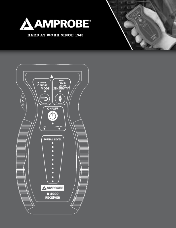
R-4000 Receiver
It has two built-in detectors that are tuned to pick up the 32.768Khz
signals generated by the T-4000-A transmitter. The R-4000 is designed
to display the signal strength to enable quick locating of the conductor
carrying the signal.
T-4000-A Transmitter
When connected to an energized circuit, the T-4000-A will filter
the low frequencies up to 400Hz and rapidly indicate on the display
that the wire is energized. When the user starts the transmission, a
combination of signals is injected on top of the 50, 60, or 400Hz that
causes a slight, periodic current fluctuation and allows the power
line to emit its own, traceable signal. This signal can be detected
back to the main generator. However, the signal will not interfere
with any sensitive electronic equipment and does not require power
interruption. The unit is intrinsically safe and has a ‘LOW’ signal
transmission setting that must be used when tracing GFCI-protected
circuits.
5

➊
➋
➌
R-4000
Receiver
➊ LED Indicator:
ON - OPEN
OFF - SHORT
Mode control
➋
Sensitivity control thumbwheel
➌
LED Indicator:
➍
ON - High sensitivity
BLINKING - Medium sensitivity
OFF - Low sensitivity for breakers
Sensitivity control
➎
Power ON/OFF
➏
LED Indicator:
➐
Green - Unit ON
Red - Low battery
➍
➎
➏
➐
6
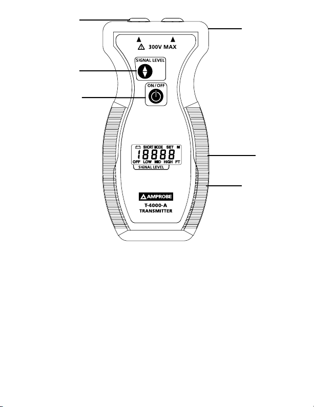
➊
➋
➌
➍
➎
T-4000-A
Transmitter
➊ Banana plug jack
Signal level switch
➋
Power ON/OFF
➌
Fuse (inside) holder
➍
24 Volt jack
➎
9V Battery compartment
➏
7
➏

When connecting to a circuit as a load, the signal will be present
anywhere between the T-4000-A and the power source. Line side or
upstream, no signal will be present on wiring on the other side of the
transmitter (load side or downstream). For example, a transmitter
connected to a circuit breaker will produce no signal on that circuit. It
will, however, cause a signal to be generated between that panel and
the transformer and beyond. When connecting to a non-energized
circuit, the live indication on the display will remain ‘OFF’. When the
user starts the transmission, the transmitter injec ts a combination of
signals onto the conductor. The signal will travel along the conductor
until it ends. There is no difference in the functional mode of the
unit when tracing energized and non-energized circuits. On an open
line, no current will flow, so the injected signal will present itself as
a voltage spike along the wire which is detected by the R-4000 in
the ‘OPEN’ mode. When the conductor is part of a complete circuit,
the voltage causes a current to flow which produces a signal that is
detected in the ‘SHORT’ mode. The T-4000-A contains a 9V battery. A
24V input jack accepts the B2024 rechargeable battery or the B2025
110V converter, both use when a very strong signal is necessar y.
(Note: When using the battery booster (B2024 or B2025) the unit will
work in ultra high “U-HI” mode only. Remove the battery booster to
return to normal operation.)
A2202 Clamp-On Transmitter Accessory
Enables the T-4000-A to induce its signal onto a non-energized or
energized circuit. Plug the A2202 into the T-4000-A and clamp it
around any conductor in a non-energized circuit, or the hot wire in
an energized circuit. The signal will be induced on top of the 50, 60,
or 400Hz frequency which may be present. The A2202 acts like a 0.5
V battery when clamped around a conductor. On a complete circuit,
this voltage will cause about 80mA of current to flow on top of the
whatever frequency is present.
To increase the signal strength, loop the wire around the clamp a few
times or use the B2024 battery Pack. The A2202 will allow wire tracing
8
 Loading...