

Amprobe AMP-330-TRMS Operating Manual

MAX 1000A
1000V CAT III
600V CAT IV
TRMS
NCV(EF
AMP-330
AMP-330-EUR
1000A ACDC TRMS
CAT IV Clamp
Multimeter
)
OFF
HOLD
ZERO
REC
COM
SELECT
CAT III
1000V
CAT IV
600V
CRESTPEAK-RMS
Hz


AMP-330 / AMP-330-EUR
1000A ACDC TRMS CAT IV Clamp Multimeter
User Manual
English
7/2014, 6003318 A
©2014 Amprobe Test Tools.
All rights reserved. Printed in Taiwan

Limited Warranty and Limitation of Liability
Your Amprobe product will be free from defects in material and workmanship for one year from
the date of purchase unless local laws require otherwise. This warranty does not cover fuses,
disposable batteries or damage from accident, neglect, misuse, alteration, contamination, or
abnormal conditions of operation or handling. Resellers are not authorized to extend any other
warranty on the behalf of Amprobe. To obtain service during the warranty period, return the
product with proof of purchase to an authorized Amprobe Service Center or to an Amprobe
dealer or distributor. See Repair Section for details. THIS WARRANTY IS YOUR ONLY REMEDY.
ALL OTHER WARRANTIES - WHETHER EXPRESS, IMPLIED OR STATUTORY - INCLUDING IMPLIED
WARRANTIES OF FITNESS FOR A PARTICULAR PURPOSE OR MERCHANTABILITY, ARE HEREBY
DISCLAIMED. MANUFACTURER SHALL NOT BE LIABLE FOR ANY SPECIAL, INDIRECT, INCIDENTAL
OR CONSEQUENTIAL DAMAGES OR LOSSES, ARISING FROM ANY CAUSE OR THEORY. Since
some states or countries do not allow the exclusion or limitation of an implied warranty or of
incidental or consequential damages, this limitation of liability may not apply to you.
Repair
All Amprobe returned for warranty or non-warranty repair or for calibration should be
accompanied by the following: your name, company’s name, address, telephone number, and
proof of purchase. Additionally, please include a brief description of the problem or the service
requested and include the test leads with the meter. Non-warranty repair or replacement
charges should be remitted in the form of a check, a money order, credit card with expiration
date, or a purchase order made payable to Amprobe.
In-warranty Repairs and Replacement – All Countries
Please read the warranty statement and check your battery before requesting repair. During
the warranty period, any defective test tool can be returned to your Amprobe distributor for
an exchange for the same or like product. Please check the “Where to Buy” section on www.
Amprobe.com for a list of distributors near you. Additionally, in the United States and Canada,
in-warranty repair and replacement units can also be sent to an Amprobe Service Center (see
address below).
Non-warranty Repairs and Replacement – United States and Canada
Non-warranty repairs in the United States and Canada should be sent to an Amprobe Service
Center. Call Amprobe or inquire at your point of purchase for current repair and replacement rates.
USA: Canada:
Amprobe Amprobe
Everett, WA 98203 Mississauga, ON L4Z 1X9
Tel: 877-AMPROBE (267-7623) Tel: 905-890-7600
Non-warranty Repairs and Replacement – Europe
European non-warranty units can be replaced by your Amprobe distributor for a nominal
charge. Please check the “Where to Buy” section on www.Amprobe.eu for a list of
distributors near you.
Amprobe Europe*
Beha-Amprobe
In den Engematten 14
79286 Glottertal, Germany
Tel.: +49 (0) 7684 8009 - 0
www.Amprobe.eu
*(Correspondence only – no repair or replacement available from this address. European customers please
contact your distributor.)

AMP-330 1000A ACDC TRMS CAT IV Clamp Multimeter
CONTENTS
SYMBOL ......................................................................................................... 3
SAFETY INFORMATION ................................................................................. 4
UNPACKING AND INSPECTION ..................................................................... 5
MEASUREMENTS ........................................................................................... 6
Measuring AC and DC Voltage ................................................................ 7
Voltage detection (NCV) .......................................................................... 8
Measuring AC and DC Current ................................................................ 9
Precise Low-Current Measurement ......................................................... 10
Microamps μA Measurement .................................................................. 11
Measuring Resistance, Continuity and Diode ........................................ 12
Measuring Capacitance and Temperature ............................................. 13
Measuring
Auto Power Off ........................................................................................ 15
SPECIFICATIONS ............................................................................................. 16
ELECTRICAL SPECIFICATIONS ....................................................................... 17
MAINTENANCE AND REPAIR ........................................................................ 21
BATTERY REPLACEMENT ............................................................................... 21
& 3-Phase Rotation .................................................. 14
AMP-330 1000A ACDC TRMS CAT IV Clamp Multimeter
8
9
1
10
2
1
3
1
4
11
12
1
5
1
6
7
1
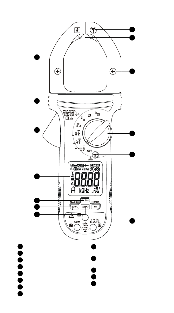
Jaw
2
Tactile Barrier
3
Jaw Release
4
Display
5
Backlight/Flashlight Button
6
REC/PEAK-RMS Button
7
SELECT Button
8
Antenna for Non-Contact
Voltage Detection
13
9
Precise Low Current
Measuring Location
10
Indicator of the Jaw Center
for Current Measurement
11
Rotary Switch
12
Data Hold/ZERO button
13
Input Terminals

26
25 24 23 22
14
15
16
17
14
Low battery indicator
Data hold
15
Alternative Current (AC)
Direct Current (DC)
AC + DC
Varable Frequency Dive
16
Negative reading
17
Relative zero is active
18
Precise low current
measurement mode
19
kΩ: KiloOhms
Hz: Hertz
20
μF: Microfarads
μA: Microamps
A: Amps
V: Volts
18 19
21
20
21
Motor rotation indicator
Phase rotation indicator
22
PEAK-RMS mode
(in-rush current) is active
23
Continuity buzzer is active
24
Diode test mode is active
25
Recording mode is active
Crest mode is active
MAX: MAX mode is active
MIN: MIN mode is active
AVG: AVG mode is active
26
Auto-ranging
SYMBOLS
W
T
J
CAT IV
Application and removal from hazardous live conductors
permitted
Caution! Risk of electric shock.
Caution! Refer to the explanation in this manual.
The equipment is protected by double insulation or reinforced
insulation.
Earth (Ground).
Overvoltage Category IV is for installed at or near the origin of
electrical supply to a building, between the building entrance
and the main distribution board. Such equipment may include
electricity tariff meters and primary over current protection
devices.
3

Overvoltage Category lll is for equipment intended to form
CAT III
part of a building wiring installation. Such equipment includes
socket outlets, fuse panels, and some mains installation control
equipment.
Alternating Current (AC).
B
Direct Current (DC).
F
Battery.
N
Underwriters Laboratories. [Note: Canadian and US.]
Complies with European Directives.
P
Conforms to relevant Australian standards.
Do not dispose this product as unsorted municipal waste.
=
Contact aqualified recycler.
SAFETY INFORMATION
The Meter complies with:
• UL/IEC/EN 61010-1, CAN/CSA C22.2 No. 61010-1, Pollution Degree 2,
Measurement category IV 600 V and Measurement category III 1000 V
• IEC/EN 61010-2-033
• IEC/EN 61010-2-032
• IEC/EN 61010-031 (test leads)
• EMC IEC/EN 61326-1
Measurement Category IV (CAT IV) is for installed at or near the origin of
electrical supply to a building, between the building entrance and the main
distribution board. Such equipment may include electricity tariff meters and
primary over current protection devices.
Measurement Category III (CAT III) is for equipment intended to form part
of a building wiring installation. Such equipment includes socket outlets,
fuse panels, and some mains installation control equipment.
CENELEC Directives
The instruments conform to CENELEC Low-voltage directive 2006/95/EC and
Electromagnetic compatibility directive 2004/108/EC.
W
Warning: Read Before Using
To avoid possible electric shock or personal injury:
• Use the Meter only as specified in this manual or the protection
provided by the Meter might be impaired.
• Avoid working alone so assistance can be rendered.
• Never measure AC current while the test leads are inserted into the
input jacks.
• Do not use the Meter in wet or dirty environments.
• Do not use the Meter if it appears damaged. Inspect the Meter before
use. Look for cracks or missing plastic. Pay particular attention to the
insulation around the connectors.
• Inspect the test leads before use. Do not use them if insulation is
damaged or metal is exposed.
4
 Loading...