

Page 1

Users Manual
Mode d’emploi•
Bedienungshandbuch•
Manual de uso•
AC40C
AD40B
Mini Clamp Meters
Page 2

Page 3

AC40C
AD40B
Mini Clamp Meters
Users Manual
AC40C_Rev001
© 2009 Amprobe Test Tools.
All rights reserved.
1
English
Page 4

Limited Warranty and Limitation of Liability
Your Amprobe product will be free from defects in material and
workmanship for 1 year from the date of purchase. This warranty does not
cover fuses, disposable batteries or damage from accident, neglect, misuse,
alteration, contamination, or abnormal conditions of operation or handling.
Amprobe’s warranty obligation is limited, at Amprobe’s option, to refund
of the purchase price, free of charge repair, or replacement of a defective
product . Resellers are not authorized to extend any other warranty on
Amprobe’s behalf. To obtain service during the warranty period, return the
product with proof of purchase to an authorized Amprobe Test Tools Service
Center or to an Amprobe dealer or distributor. See Repair Section for details.
This warranty is your only remedy . All other warranties - whether express,
implied or statutory - including implied warranties of fitness for a particular
purpose or merchantability, are hereby excluded. Neither Amprobe nor its
parent company or affiliates shall be liable for any special, indirect, incidental
or consequential damages or losses, arising from any cause or theory. Since
some states or countries do not allow the exclusion or limitation of an
implied warranty or of incidental or consequential damages, this limitation of
liability may not apply to you.
Repair
All test tools returned for warranty or non-warranty repair or for calibration
should be accompanied by the following: your name, company’s name,
address, telephone number, and proof of purchase. Additionally, please
include a brief description of the problem or the service requested and
include the test leads with the meter. Non-warranty repair or replacement
charges should be remitted in the form of a check, a money order, credit
card with expiration date, or a purchase order made payable to Amprobe®
Test Tools.
In-Warranty Repairs and Replacement – All Countries
Please read the warranty statement and check your battery before requesting
repair. During the warranty period any defective test tool can be returned to
your Amprobe® Test Tools distributor for an exchange for the same or like
product. Please check the “Where to Buy” section on www.amprobe.com for
a list of distributors near you. Additionally, in the United States and Canada
In-Warranty repair and replacement units can also be sent to a Amprobe®
Test Tools Service Center (see below for address).
Non-Warranty Repairs and Replacement – US and Canada
Non-warranty repairs in the United States and Canada should be sent to a
Amprobe® Test Tools Service Center. Call Amprobe® Test Tools or inquire at
your point of purchase for current repair and replacement rates.
In USA In Canad a
Amprob e Test Tools Amprob e Test Tools
Everet t, WA 98203 Missis sauga, ON L4Z 1X9
Tel: 888 -993-5 853 Tel: 905- 890-7600
Fax: 425 -446- 6390 Fax: 905- 890-68 66
Non-Warranty Repairs and Replacement – Europe
European non-warranty units can be replaced by your Amprobe® Test Tools
distributor for a nominal charge. Please check the “Where to Buy” section on
www.amprobe.com for a list of distributors near you.
European C orresponden ce Address*
Amprob e® Test Tool s Europe
Beha-A mprobe GmbH
In den Eng ematte n 14
79286 Glo tter tal, Ger many
Tel.: +49 (0) 76 84 8009 – 0
*(Correspondence only – no repair or replacement available from this
address. European customers please contact your distributor.)
2
Page 5
AC40C AD40B
CAT III
600V
COM
600V
MAX
400A
CAT 600V
MAX
HOLD
AC
DC
A
100 20 4030
CAT III
600V
MAX400A
CAT 600V
HOLD
A
100 20 4030
1
3
6
7
5
2
2
4
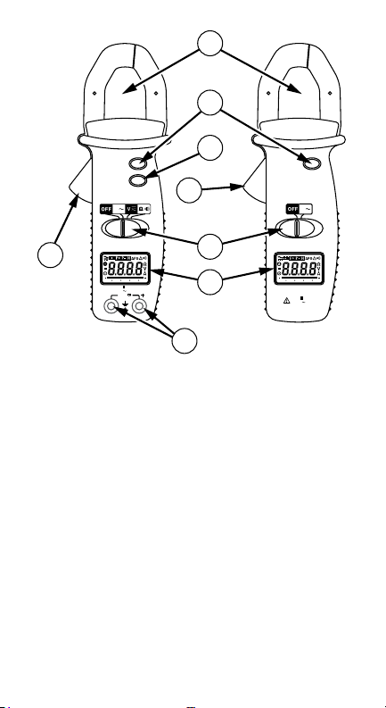
➊ Transformer Jaws: Designed to pick up the AC current
flowing through the conductor.
➋ Jaw Opening Lever: Press lever to open transformer jaws.
When pressure on lever is released, the jaws will close again.
➌Selector Switch: Turns instrument on and off and selects the
measuring function.
➍ AC/DC selector switch (AC40C): With the selector switch set
to voltage measurement, this button selects between AC
and DC voltage.
Data Hold Switch: Holds reading for all functions and
➎
ranges. Press again to release HOLD before taking a new
measurement.
Digital Display: 3-3/4 digit LCD (max reading 3999) with
➏
decimal point, low battery N, Auto-range, Data Hold l,
and unit indicators, plus, for the AC meter: ACB, DCF,
Polarity — ) and continuity R.
Input Terminals (AC meters): Connect the black test lead
➐
to the “COM” input and red lead to the “+” input when
measuring voltage, resistance and continuity (AC40C).
3
Page 6

AC40C / AD40B
Mini Clamp Meters
CONTENTS
Symbols ............................................................................................5
Warnings and Precautions ................................................... 5
Introduction ..................................................................................... 6
Unpacking and Inspection ......................................................... 6
AC Current Measurement (Fig. 1) ..................................................6
AC & DC Voltage Measurement (AC40C) (Fig. 2) ..........................7
Resistance & Continuity Measurement (AC40C) (Fig. 3) ...............7
Display Hold ..................................................................................... 7
Specifications ................................................................................... 7
Troubleshooting & Maintenance .................................................10
Battery Replacement ...............................................................10
4
Page 7

SYMBOLS
Battery
N
Double
insulated
Direct Current
F
Alternating
B
Current
Complies with
EU directives
Warnings and Precautions
This instrument is EN61010-1:2001 and EN61010-2-32 •
certified for Installation Category III. It is recommended for
use with local level power distribution, appliances, portable
equipment, etc, where only smaller transient overvoltages
may occur, and not for primary supply lines, overhead lines
and cable systems.
This instrument must not be used on uninsulated conductors •
at a voltage greater than 600V ac/dc.
Use extreme caution when working around bare conductors •
and bus bars.
Do not exceed the instrument overload limits per function •
(see specifications) nor the limits marked on the instrument.
Exercise extreme caution when: measuring voltage >60 V •
DC or 30 V AC RMS // current >10 mA // AC power lines with
inductive loads // AC power lines during electrical storms //
servicing CRT equipment. High voltages can be lethal and
high voltage transients may occur at any time.
Never measure current while test leads are inserted in the •
input jacks.
Always inspect your instrument, test leads and accessories for •
signs of damage or abnormality before every use. If abnormal
conditions exist (broken or damaged test leads, cracked case,
display not reading, etc.), do not use.
When making voltage measurements, make sure these •
ranges function correctly. Take a reading of a known voltage
first.
R
Refer to the
manual
Dangerous
Voltage
Earth Ground
Audible tone
Application
around and
removal from
hazardous live
conductors is
permitted
5
Page 8

Never ground yourself when taking measurements. Do not •
touch exposed metal pipes, outlets, fixtures, etc., which
might be at ground potential. Keep your body isolated from
ground and never touch exposed wiring, connections, test
probe tips, or any live circuit conductors.
Do not operate the instrument in an explosive atmosphere •
(flammable gases, fumes, vapor, dust).
Do not use this or any piece of test equipment without •
proper training. Read the operating instructions before use
and follow all safety instructions.
Use the meter only as specified in this manual; otherwise the •
meters safety circuitry may not protect you.
Use extreme caution when working around bare conductors. •
Contact with the conductor could result in electric shock.
The ridge at the top of the clamp body is intended to keep •
hands and fingers away from hazardous live conductors.
INTRODUCTION
The AD40B is an average sensing and RMS (sine wave) indicating
AC current clamp. The AC40C is an average sensing and RMS
(sine wave) indicating AC current clamp meter that also
measures AC and DC voltage, resistance and continuity.
Unpacking and Inspection
Your shipping carton should include the digital clamp meter ,
a carrying case, two 1.5 V AAA (UM-2) batteries (installed), and
this manual plus one test lead set (one black, one red) for the
AC40C meter. If any of the items are damaged or missing, return
the complete package to the place of purchase for an exchange.
AC CURRENT MEASUREMENT (FIG. 1)
Set the slide switch to AC1. B position.
Open spring-loaded clamp by pressing lever on left side of 2.
meter.
Position clamp around wire or conductor and release clamp 3.
lever. Make sure that the conductor is centered in the clamp
and that the clamp is entirely closed. The clamp must be
positioned around only one conductor. If it is placed around
two or more current carrying conductors, the reading is
FALSE.
Read the measured value on the display. If the measured 4.
value exceeds the highest range for a period of time,
overheating may occur. Interrupt measurement.
6
Page 9

Note
Do not measure current on high-voltage conductors (>600 V) in
order to avoid risk of discharge and/or incorrect reading.
AC & DC VOLTAGE MEASUREMENT (AC40C) (FIG. 2)
Connect the black test lead to the COM input and the red 1.
test lead to the “+” input.
Set the selector switch to V 2. C position.
Press the AC DC button to select AC or DC voltage (3. B or F is
displayed).
Connect probe tips to circuit, in parallel to the load.4.
Read the measured value on the display.5.
RESISTANCE & CONTINUITY MEASUREMENT (AC40C) (FIG. 3)
Remove any voltage from resistance to be measured and 1.
discharge all capacitors.
Connect the black test lead to the COM input and the red 2.
test lead to the “+” input.
Set the selector switch to 3. Ω R position.
Connect the probe tips across the circuit or resistance.4.
Read the measured value on the display.5.
The instrument emits a continuous tone and the R symbol is
displayed when the measured resistance is < 40 Ω.
DISPLAY HOLD
Press the HOLD button to keep the measured value on the
display for later viewing. Press HOLD again to release the
“Display Hold” function before taking a new measurement.
Display Hold can be applied to all measuring functions.
SPECIFICATIONS
General Specifications
Display: (AC40C & AD40B) 3-3/4 digit LCD (max. reading 3999).
Polarity Indication: Automatic, negative indicated, positive
implied
Overrange Indication: “OL” indicated.
Measuring Principle: Dual slope integration.
Range Selection: Automatic.
Low Battery Indication: N when battery voltage falls below
operating voltage.
7
Page 10

Auto Power Off (APO): Approx. 30 minutes after no function
change.
Environmental Conditions
This instrument is designed for indoor use.
Altitude: < 2000 m
Operating Temperature: 0 °C to +40 °C (32˚F to 104˚F),
<80 % R.H., non-condensing.
Storage Temperature: -10 °C to +60 °C (14˚F to 140˚F),
<70 % R.H., non-condensing, batteries removed.
Power Supply: Two 1.5V AAA batteries (AC40C).
Battery Life: Alkaline 100 hours, approx.
Maximum Jaw Opening: 25.4 mm (1.0 in).
Dimensions/Weight, AD40B (WxHxD): 64x190x36mm (2.5 x 7.5 x
1.42) / 250g (0.55 Lb) (incl. battery).
Dimensions/Weight, AC40C (WxHxD): 64x190x36mm (2.5 x 7.5 x
1.42) / 280g (0.62 lb) (incl. battery).
Accessories: Manual, carrying case, test leads (AC40C).
Replacement Parts: Test lead set - TL245
Safety: meets EN 61010-1:2001 Cat III - 600V Pollution Degree:
Level II, EN 61010-2-032
EMC: meets EN61326-1.
Agency Approvals:
This product complies with requirements of the following
European Community Directives: 89/336/EEC (Electromagnetic
Compatibility) and 73/23/EEC (Low Voltage) as amended by
93/68/EEC (CE Marking). However, electrical noise or intense
electromagnetic fields in the vicinity of the equipment may
disturb the measurement circuit. Measuring instruments will
also respond to unwanted signals that may be present within
the measurement circuit. Users should exercise care and take
appropriate precautions to avoid misleading results when
making measurements in the presence of electronic interference.
Electrical Specifications
Accuracy is ±(%reading + nbr digits) at 23°C ±5°C, <80% R.H.
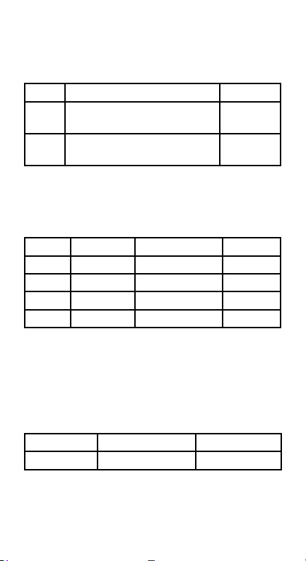
DC Voltage (AC40C)
Range Accuracy Resolution
400 V ±(1.0 %rdg +5 dgt) 0.1 V
600 V ±(1.0 %rdg +5 dgt) 1 V
8
Page 11
Input Impedance: 1 MΩ
Overload Protection: 600 V rms
AC Voltage (AC40C)
Range Accuracy (40 – 450 Hz) Resolution
400 V ±(1.5 %rdg +10 dgt)
50-60Hz;(+/-3% rdg + 15dgts) 400Hz
600 V ±(1.5 %rdg +10 dgt)
50-60Hz;(+/-3% rdg + 15dgts) 400Hz
Input Impedance: 1 MΩ
Measuring method: Dual slope integration. Average Sensing,
rms indication. Overload Protection: 600 V rms
AC Current (AC40C/AD40B)
Range Frequency Accuracy Resolution
40A 50/60 Hz ±(2.5%rdg +10dgt) 0.01A
40A 60 – 400 Hz ±(4.0%rdg +10dgt) 0.01A
400A 50/60 Hz ±(2.5%rdg +10dgt) 0.1A
400A 60 – 400 Hz ±(4.0%rdg +10dgt) 0.1A
Overload Protection: 660 A
Accuracies are specified for conductor centered in the jaw. If
the conductor is not centered, an additional error of max 1.5%
can result.
Measuring method: Dual slope integration. Average Sensing,
rms indication.
Resistance (AC40C)
Range Accuracy Resolution
400 Ω ±(1.0 %rdg + 5 dgt) 0.1 Ω
Max open circuit voltage, AC40C: -1.2 V nominal
Overload Protection, AC40C: 600 Vrms
0.1 V
1 V
9
Page 12

Audible Continuity (AC40C)
Like resistance measurement. Continuous tone and R display at
R ≤40 Ω for AC40C
Max open circuit voltage: -1.2 V
Overload Protection: 600 Vrms
Data Hold: Hold display reading for all functions and ranges.
Always remember to release Data Hold when taking a new
measurement.
TROUBLESHOOTING & MAINTENANCE
In case of malfunction during the operation of the meter, the
following steps should be performed in order to isolate the
cause of the problem:
Check the batteries.1.
Review the operating instructions for possible mistakes in 2.
operating procedure.
Check clamp against a known current source.3.
Check test leads for continuity (voltage and resistance).4.
Except for the replacement of the batteries, repair of the clamp
should be performed only by a Factory Authorized Service
Center or by other qualified instrument service personnel.
Front panel and case can be cleaned with a mild solution of
detergent and water. Apply sparingly with a soft cloth and let
dry completely before using. Do not use aromatic hydrocarbons
or chlorinated solvents for cleaning.
Battery Replacement
The meter is powered by two 1.5 V AAA batteries. Replace
batteries as soon as N symbol is displayed.
Turn meter off. Disconnect and remove the test leads.1.
Position the meter face down. Remove the two screws and 2.
lift off rear case.
Replace the batteries.3.
Reassemble the case.4.
10
Page 13

AC40C
AD40B
Mini Clamp Meters
Mode d’emploi
AC40C_Rev001
© 2009 Amprobe Test Tools.
Tous droits réservés.
11
Français
Page 14

Limites de garantie et de responsabilité
Amprobe g arantit l’absence d e vices de matériau x et de fabrication d e ce produit
pendant u ne période d’un an pr enant effet à la dat e d’achat. Cette ga rantie ne
s’applique p as aux fusibles , aux piles jetable s ni à tout produit mal u tilisé, modifié,
contamin é, négligé ou endo mmagé par acciden t ou soumis à des cond itions anormale s
d’utilisa tion et de manipulati on. L’obligation de garant ie d’Amprobe est limi tée, au
choix d’Ampr obe, au rembour sement du prix d’ach at ou à la réparation/ remplacement
gratuit d’un p roduit défec tueux. Les dist ributeurs agréé s par Amprobe ne so nt pas
autorisé s à appliquer une ga rantie plus étendu e au nom d’Amprobe. Po ur bénéficier
de la garanti e, renvoyez le produi t accompagné d’un ju stificatif d’acha t auprès d’un
centre de se rvices agréé p ar Amprobe Test Tools ou d ’un distributeur o u d’un revendeur
Amprobe . Voir la section Répa ration pour tous le s détails. La pré sente garantie es t
le seul et exc lusif recours tou tes autres garant ies, explicite s, implicites ou st atutaires,
notamme nt le cas échéant le s garanties de quali té marchande ou d’ada ptation a un
objecti f particulier so nt exclues par les pr ésentes. Amp robe, la société mè re ou ses
filiales ne p euvent en aucun ca s être tenues resp onsables des do mmages parti culiers,
indirec ts, accidentel s ou consécutif s, ni d’aucuns dégât s ou pertes de do nnées, sur une
base contr actuelle, ext ra-contrac tuelle ou autre. Eta nt donné que cert aines juridicti ons
n’admette nt pas les limitati ons d’une conditio n de garantie implici te, ou l’exclusion ou
la limitati on de dégâts accid entels ou conséc utifs, il se peut q ue les limitation s et/ou les
exclusio ns de cette garanti e ne s’appliquent pas à v otre cas.
Réparation
Tous les outil s de test renvoyés po ur un étalonnage o u une réparation cou verte ou
non par la gara ntie doivent être a ccompagnés des é léments suivan ts : nom, raison
sociale, a dresse, numéro d e téléphone et ju stificatif d’achat . Ajoutez égalem ent une
brève des cription du problè me ou du service d emandé et incluez le s cordons de mesu re
avec l’appar eil. Les frais de remp lacement ou de rép aration hors garan tie doivent être
acquitt és par chèque, man dat, carte de cr édit avec date d’exp iration, ou par bon de
commande p ayable à l’ordre de Am probe® Test Tools.
Remplacements et réparations sous garantie – Tous pays
Veuillez lire la d éclaration de garan tie et vérifier la pile a vant de demander un e
réparatio n. Pendant la pério de de garantie, tou t outil de test défe ctueux peut êt re
renvoyé aup rès de votre distrib uteur Amprobe ® Test Tools pour être éch angé contre un
produit id entique ou similair e. Consultez la sec tion « Where to Buy » su r le site www.
amprobe .com pour obtenir la l iste des distrib uteurs dans votr e région. Au Canada e t
aux Etats -Unis, les app areils devant être r emplacés ou répar és sous garantie p euvent
égaleme nt être envoyés dans u n centre de servi ces Amprobe® Test Tool s (voir les
adresses ci-dessous).
Remplacements et réparations hors garantie – Canada et Etats-Unis
Les appar eils à réparer hors g arantie au Canada e t aux Etats-Uni s doivent être envoy és
dans un cent re de services A mprobe® Test Tools. A ppelez Amprobe ® Test Tools ou
renseig nez-vous auprès d e votre lieu d’achat pou r connaître les ta rifs en vigueur de
remplace ment ou de réparati on.
Aux Etat s-Unis Au Canada
Amprob e Test Tools Ampro be Test Tools
Everet t, WA 98203 E -U Missi ssauga, ON L4Z 1X 9 Canada
Tel: 877-993- 5853 Tel: 905 -890-760 0
Fax: 425 -446- 6390 Fax: 905 -890- 6866
Remplacements et réparations hors garantie – Europe
Les appar eils européens n on couverts par l a garantie peuvent ê tre remplacés par v otre
distribu teur Amprobe® Tes t Tools pour une somme n ominale. Consul tez la section «
Where to Bu y » sur le site www.a mprobe.com pour o btenir la liste de s distributeur s
dans votre r égion.
Adress e postale europ éenne*
Amprob e® Test Tool s Europe
Beha-A mprobe GmbH
In den Eng ematte n 14
79286 Glo tter tal, Ger many
Tel.: +49 (0) 76 84 8009 – 0
*(Réser vée à la correspon dance – Aucune répa ration ou remplace ment n’est possib le à
cette adr esse. Nos client s européens doi vent contacter l eur distribute ur.)
12
Page 15

AC40C AD40B
CAT III
600V
COM
600V
MAX
400A
CAT 600V
MAX
HOLD
AC
DC
A
100 20 4030
CAT III
600V
MAX400A
CAT 600V
HOLD
A
100 20 4030
1
3
6
7
5
2
2
4
➊ Pince: Capte le courant qui passe par le conducteur.
Levier de la Pince: Poussez ce levier pour ouvrir la pince. La
➋
pince ferme quand la pression est relachée.
➌Sélecteur de Fonctions: Allume et éteint l’appareil et
sélectionne la fonction de mesure.
➍ Sélecteur CC/CA: Avec le sélecteur de fonctions mis sur
mesure de tension, cette touche choisit entre Tension CC et
Tension CA.
Bouton Data Hold: Maintient la lecture pour toutes
➎
fonctions et gammes.
Affichage Digital: LCD 3-3/4 digits (lecture max 3999)
➏
avec indicateurs de point décimal, de pile déchargée N,
sélection automatique, Data Hold l et unités, plus, pour les
instrument AC: ACB, DCF, polarité, et continuité R.
Entrées: Pour les mesures de tension, de résistance et de
➐
continuité, connectez toujours le cordon de mesure noir à
l’entrée COM, et le rouge à l’entrée “+” (AC40C).
13
Page 16

AC40C / AD40B
Mini Clamp Meters
Symboles ........................................................................................ 15
Avertissements et Précautions ........................................... 15
Introduction ................................................................................... 16
Désemballage et inspection ....................................................16
Mesure de Courant Alternatif (fig. 1) ..........................................16
Mesure de Tension Continue et Alternative (AC40C) (fig. 2) ..... 17
Mesure de Résistance et de Continuité (AC40C) (fig. 3) ............. 17
Maintien d’Affichage .................................................................... 17
Spécifications ................................................................................. 17
Dépannage et Maintenance ......................................................... 20
Remplacement de la Pile .........................................................20
14
Page 17

SYMBOLES
Pile
N
Double isolation
Courant continu
F
Courant
B
alternatif
Conforme aux
directives de l’UE
Avertissements et Précautions
Cet instrument est certifié EN61010-1 :2001 et EN61010-2-32 •
catégorie d’installation III. Son utilisation est recommandée
pour le niveau de distribution local, appareils ménagers,
appareils portatifs, etc, où les surtenstions transitoires son
limitées, et non pour les installations de puissance et lignes
de transmission et câblages à haute tension.
N’utilisez pas cet appareil avec des conducteurs non-isolés à •
des tensions supérieures à 600 V ca/cc.
Soyez très prudent quand vous mesurez sur des câbles non-•
isolés et des rails de distribution.
N’excédez jamais les limites de surcharge continues par •
fonction (voir spécifications) ou d’autres limites marquées sur
l’appareil.
Soyez très prudent quand vous mesurez des tensions >60 V •
CC ou 30 V CA, ou des courants >10 mA // tension ou courant
de secteur avec charge inductive ou par temps de tempête
// dans des appareils à tube cathodique (transitoires à haute
tension).
Ne mesurez jamais du courant avec les cordons insérés dans •
l’appareil.
Inspectez appareil, câbles, connecteurs avant chaque mesure. •
N’utilisez pas des pièces endommagées.
Ne touchez pas les pointes de touche ou le circuit pendant les •
mesures. Isolezvous.
R
Se reporter au
mode d’emploi
Tension
dangereuse
Prise de terre
Signal sonore
Son application
et son retrait
à proximité de
conducteurs
sous tension
dangereuse
sont autorisés.
15
Page 18

N’utilisez pas cet appareil dans des atmosphères explosives.•
N’utilisez pas cet appareil sans formation adéquate. Lisez •
le mode d’emploi avant l’utilisation et suivez les conseils de
sécurité.
Utiliser l’appareil en respectant les consignes de sécurité de •
ce manuel afin de ne pas entraver les circuits de sécurité et la
protection de l’utilisateur.
Faire preuve d’extrême prudence en travaillant à proximité •
des conducteurs nus Tout contact avec le conducteur pourrait
entraîner une électrocution.
La collerette au sommet de la pince ampèremétrique est •
destinée à protéger les mains et les doigts des conducteurs
sous tension dangereuse.
INTRODUCTION
Le AD40B est des pinces de courant CA à mesure moyenne et
indication de valeur efficace (onde sinusoïdale). Le AC40C est des
pinces de courant CA à mesure moyenne et indication de valeur
efficace (onde sinusoïdale), qui mesurent également les tensions
CC et CA, la résistance et la continuité.
Désemballage et inspection
Votre emballage devrait contenir: un multimètre-pince,
une sacoche, deux piles-1.5 V AAA (UM-2) (dans l’appareil)
et ce manuel, plus, pour l’instrument AC40C, une paire de
cordons de test (un noir, un rouge). Si une pièce manque ou
est endommagée, retournez à votre point de vente pour un
échange.
MESURE DE COURANT ALTERNATIF (FIG. 1)
Placez le sélecteur sur AC1. B.
Ouvrez la pince en poussant sur le levier.2.
Placez la pince autour du conducteur et fermez la 3.
(en relachant le levier). Assurez-vous que la pince est
complètement fermée et qu’elle ne contient qu’un seul
conducteur. Si elle en contient plusieurs, la mesure est
faussée.
Lisez la valeur affichée. Si la valeur mésurée dépasse 4.
la gamme la plus élevée, l’appareil peur surchauffer.
Interrompez la mesure.
Note
Ne mesurez pas des courants sur des lignes de haute tension
(>600 V) afin d’éviter des chocs électriques et/ou des mesures
erronnées.
16
Page 19

MESURE DE TENSION CONTINUE ET ALTERNATIVE (AC40C)
(FIG. 2)
Connectez le cordon noir à l’entrée COM et le rouge à 1.
l’entrée “+”.
Placez le sélecteur sur V 2. C.
Pressez le bouton(insert AC/DC key cap) pour sélectionner 3.
la mesure de tension alternative ou continue (B ou F est
affiché).
Connectez les pointes de touche au circuit (en parallèle avec 4.
la source de tension).
Lisez la valeur affichée.5.
MESURE DE RÉSISTANCE ET DE CONTINUITÉ (AC40C) (FIG. 3)
Coupez l’alimentation du circuit à mesurer et déchargez les 1.
condensateurs.
Connectez le cordon noir à l’entrée COM et le rouge à 2.
l’entrée “+”.
Placez le sélecteur sur 3. Ω R.
Connectez les pointes de touche au circuit.4.
Lisez la valeur affichée.5.
Un signal sonore retentit et R est affiché quand R < 40
MAINTIEN D’AFFICHAGE
Presser la touche HOLD maintient l’affichage pour visualisation
ultérieure. Pressez HOLD à nouveau avant de prendre une
nouvelle mesure afin de libérer l’affichage. HOLD peut être
appliqué à toutes les fonctions de mesure.
SPÉCIFICATIONS
Spécifications Générales
Afficheur: (AC40C & AD40B) LCD 3-3/4 digits (lecture max. 3999).
Indication de polarité: automatique; négative indiquée, positive
sous-entendue
Indication de Dépassement de Calibre: “OL”.
Méthode de mesure: intégration à double rampe.
Sélection de gammes: automatique.
Indication de pile déchargée: N, quand la tension tombe en-
dessous du niveau de fonctionnement.
Coupure automatique (APO) : Après environ 30 minutes
d’inactivité.
Ω.
17
Page 20

Conditions d’Environnement
Cet instrument est conçu pour utilisation à l’intérieur
Altitude: < 2000 m
Température d’utilisation: 0 °C à +40 °C (32˚F to 104˚F),
<75 % H.R., sans condensation.
Température de Stockage: -10 °C à +60 °C (14˚F to 140˚F),
<70 % H.R., sans condensation, pile enlevée.
Alimentation: deux piles-bouton 1.5 V (IEC LR44, NEDA 116 A
ou A76)
Autonomie: Alkaline 100 heures, approx.
Ouverture max. de la Pince: 27 mm (1.0 in).
Dimensions/Poids, AD40B (LxHxP): 64x190x36mm (2.5 x 7.5 x
1.42) / 250g (0.55 Lb) (avec piles).
Dimensions/Poids, AC40C (LxHxP): 64x190x36mm (2.5 x 7.5 x
1.42) / 280 g (0.62 lb) (incl. battery).
Accessoires: piles (installées), manuel, sacoche et cordons de test
(AC40C)
Accessoires de rechange: un jeu de cordons de test - TL245.
Sécurité: selonEN 61010-1:2001 Cat III - 600V Degré de Pollution:
Niveau II, EN 61010-2-032
EMC: selon EN61326-1.
Homologations d’organismes :
Ce produit est conforme aux exigences des directives suivantes
de la Communauté Européenne: 89/336/EEC (Compatibilité
Electromagnétique) et 73/23/ EEC (Basse Tension), modifiée
par 93/68/EEC (CE Marking). Cependant, du bruit électrique
ou des champs électromagnétiques intenses dans la proximité
de l’instrument peuvent influencer le circuit de mesure.
L’instrument peut également être perturbé par des signaux
parasytes dans le circuit mesuré. L’utilisateur doit être vigilant
et prendre des précautions appropriées pour éviter des
résultats erronés quand les mesures sont prises en présence
d’interférences électromagnétiques.
Spécifications Electriques
La précison est ±(%lecture + nbr digits) à 23 °C ±5 °C, <80 % H.R.
18
Page 21

Tension Continue (AC40C)
Gamme Précision Résolution
400 V ±(1.0 %lect +5 dgt) 0.1 V
600 V ±(1.0 %lect +5 dgt) 1 V
Impédance d’entrée: 1 MΩ
Protection de surcharge: 600 V rms
Tension Alternative (AC40C)
Gamme Précision (40 – 450 Hz) Résolution
400 V ±(1.5 %lect +10 dgt)
50-60Hz;(+/-3% rdg + 15dgts) 400Hz
600 V ±(1.5 %lect +10 dgt)
50-60Hz;(+/-3% rdg + 15dgts) 400Hz
Impédance d’entrée: 1 MΩ
Méthode de mesure: Intégration à double rampe.
Mesure de la valeur moyenne; affichage de la valeur efficace
(onde sinusoïdale).
Protection de surcharge: 600 V rms
Courant Alternatif (AC40C/AD40B)
Gamme Fréquence Précision Résolution
40A 50/60 Hz ±(2.5%lect +10dgt) 0.01A
40A 60 – 400 Hz ±(4.0%lect +10dgt) 0.01A
400A 50/60 Hz ±(2.5%lect +10dgt) 0.1A
400A 60 – 400 Hz ±(4.0%lect +10dgt) 0.1A
Protection de surcharge: 660 A
La précision donnée s’applique pour le conducteur centré
dans la pince. Si le conducteur n’est pas centré, une erreur
supplémentaire de 1.5 % peut en résulter.
Méthode de mesure: Intégration à double rampe. Mesure
de la valeur moyenne; affichage de la valeur efficace (onde
sinusoïdale)
0.1 V
1 V
19
Page 22

Résistance (Sélection Automatique) (AC40C)
Gamme Précision Résolution
400 Ω ±(1.0 %lect + 5 dgt) 0.1 Ω
Tension en circuit ouvert, AC40C: -1.2 V nominal
Protection de surcharge, AC40C: 600 Vrms
Indication de Continuité (AC40C)
Indication sonore et affichage de à R ≤40 Ωpour AC40C.
Tension en circuit ouvert, AC40C: -1.2 V nominal
Protection de surcharge, AC40C: 600 Vrms
Maintien d’Affichage: Pressez HOLD pour maintenir l’affichage
pour toutes les fonctions et gammes. Pressez HOLD à nouveau
pour désactiver la fonction avant de pour une nouvelle mesure.
DÉPANNAGE ET MAINTENANCE
En cas de problèmes:
Vérifiez le chargement de la pile.1.
Vérifiez le mode d’emploi.2.
Mesurez une valeur de courant connue.3.
Vérifiez les câbles de mesure (tension et résistance).4.
A part le remplacement de la pile, toute réparation ne doit être
effectuée que par un centre de services agréé par Wavetek.
Le boîtier peut être nettoyé avec une savonnée douce. Laissez
secher complètement avant utilisation.
Remplacement de la Pile
L’instrument est alimenté par deux piles de 1.5 V AAA. 1.
Remplacez les piles dès que N est affiché.
Coupez l’alimentaton de l’appareil et enlevez les cordons.2.
Dévissez et enlevez le boîtier arrière.3.
Remplacez les piles et réassemblez le boîtier.4.
20
Page 23

AC40C
AD40B
Mini Clamp Meters
Bedienungshandbuch
AC40C_Rev001
© 2009 Amprobe Test Tools.
Alle Rechte vorbehalten.
21
Deutsch
Page 24

Beschränkte Gewährleistung und
Haftungsbeschränkung
Es wird gewä hrleistet, das s dieses Amprob e-Produkt f ür die Dauer von eine m Jahr ab
dem Kaufda tum frei von Materia l- und Fertigun gsdefekten is t. Diese Gewähr leistung
erstre ckt sich nicht auf Si cherungen, Einwe gbatterien od er Schäden durch U nfälle,
Nachläs sigkeit, Missbra uch, Änderung en oder abnormal e Betriebsbed ingungen bzw.
unsachg emäße Handhabu ng. Die Garantiever pflichtung von Amp robe beschränk t
sich darauf, d ass Amprobe nac h eigenem Ermess en den Kaufpreis e rsetzt oder a ber
das defek te Produkt unen tgeltlich repari ert oder aust auscht. Die Verkau fsstellen sind
nicht dazu be rechtigt, dies e Gewährleistun g im Namen von Ampro be zu erweitern . Um
während de r Gewährleistun gsperiode Se rviceleistun gen zu beanspruc hen, das Produk t
mit Kaufna chweis an ein autori siertes Ampro be Test Tools Service -Center ode r an einen
Amprobe -Fachhändle r/-Distributo r einsenden. Nä here Einzelheiten s iehe Abschnit t
„Reparatu r“. Diese Gewährleis tung stellt den ei nzigen und alleinig en Rechtsansp ruch
auf Schad enersatz dar. Alle a nderen Gewährle istungen, ver traglich gerege lte oder
gesetz lich vorgeschrie bene, einschli eßlich der geset zlichen Gewährle istung der
Marktf ähigkeit und der Eignu ng für einen best immten Zweck, we rden abgelehnt .
Weder Amp robe noch desse n Muttergese llschaft oder Toch tergesellsch aften
überneh men Haftung für s pezielle, indirek te, Neben- od er Folgeschäd en oder für
Verluste , die auf beliebiger U rsache oder Re chtstheorie be ruhen. Weil einige S taaten
oder Län der den Ausschlu ss oder die Einsch ränkung einer impl izierten Gewährl eistung
sowie den Au sschluss von Be gleit- oder Folge schäden nicht zula ssen, ist dies e
Gewährle istungsbesc hränkung möglich erweise für Sie ni cht gültig.
Reparatur
Alle Gerät en, die innerhalb o der außerhalb des G arantiezeitraums z ur Reparatur
oder Kalib rierung einges endet werden, m üssen mit folgen den Information en
und Dokume nten versehen w erden: Name des Kun den, Firmennam e, Adresse,
Telefonnummer und Kaufbeleg. Zusätzlich bitte dem Messgerät eine kurze Beschreibung
des Probl ems oder der gewü nschten Wartun g sowie die Messle itungen beileg en. Die
Gebühre n für Reparaturen au ßerhalb der Garant ie oder für den Ers atz von Instrum enten
müssen p er Scheck, Geld anweisung oder K reditkarte (Kr editkartennu mmer mit
Ablaufda tum) beglichen wer den oder es muss e in Auftrag an Ampr obe® Test Tools
formuliert werden.
Garantiereparaturen und -austausch - alle Länder
Bitte die Ga rantieerklärun g lesen und die Bat terie prüfen, be vor Reparaturen
angeford ert werden. Wäh rend der Garantie periode können alle d efekten Gerät e zum
Umtaus ch gegen dasselb e oder ein ähnliche s Produkt an den A mprobe® Test ToolsDistribu tor gesendet we rden. Ein Verzeichn is der zuständi gen Distributor en ist im
Abschni tt „Where to Buy“ (Ve rkaufsstelle n) auf der Website ww w.amprobe.co m zu
finden. Da rüber hinaus könne n in den USA und in Kanad a Geräte an ein Ampro be® Test
Tools Serv ice-Center ( Adresse siehe we iter unten) zur Repar atur oder zum Umtau sch
eingesendet werden.
Reparaturen und Ersatz außerhalb des Garantiezeitraums - USA und Kanada
Für Reparat uren außerhalb de s Garantiezeitraum s in den Vereinigten St aaten und
in Kanada we rden die Geräte an ein A mprobe® Test Tools Se rvice-Ce nter gesendet .
Auskunf t über die derzeit g eltenden Repara tur- und Austausc hgebühren erha lten Sie
von Ampro be® Test Tools oder der Ve rkaufsstelle.
In den USA : In Kanada:
Amprob e Test Tools Amprob e Test Tools
Everet t, WA 98203 U SA Missi ssauga, ON L4Z 1X 9 Kanada
Tel.: 877-993 -5853 Tel.: 9 05-890 -7600
Fax: 425 -446- 6390 Fax: 905- 890-68 66
Reparaturen und Austausch außerhalb des Garantiezeitraums - Europa
Geräte mit a bgelaufener Gar antie können durch de n zuständigen A mprobe® Test
Tools-Di stributor gege n eine Gebühr ers etzt werden. Ein Ve rzeichnis der zus tändigen
Distribu toren ist im Absc hnitt „Where to Buy “ (Verkaufsste llen) auf der Websit e www.
amprobe .com zu finden.
Korresp ondenz anschri ft für Europa*
Amprob e® Test Tool s Europe
Beha-A mprobe GmbH
In den Eng ematte n 14
79286 Glo tter tal, Deu tschland
Tel.: +49 (0) 76 84 8009 – 0
*(Nur Korres pondenz – keine Rep araturen und kein Umt ausch unter dies er Anschrift .
Kunden in Euro pa wenden sich an de n zuständigen D istributor.)
22
Page 25

AC40C AD40B
CAT III
600V
COM
600V
MAX
400A
CAT 600V
MAX
HOLD
AC
DC
A
100 20 4030
CAT III
600V
MAX400A
CAT 600V
HOLD
A
100 20 4030
1
3
6
7
5
2
2
4
➊ Stromzange: Überträgt den Strom der durch den Leiter fließt.
Zangenhebel: Hebel drücken um Zange zu öffnen. Zange
➋
schließt beim Loslassen des Hebels.
➌Funktionsschalter: Schaltet Gerät ein und aus und wählt die
Meßfunktion.
➍ AC/DC Schalter (AC40C): Mit dem Funktionsschalter auf
Spannungsmessung, wählt dieser Schalter zwischen Gleichund Wechselspannung.
Data Hold Taste: Friert die Anzeige für alle Bereiche und
➎
Funktionen. HOLD Taste immer lösen bevor Sie eine neue
Messung vornehmen.
Digitale Anzeige: 3-3/4 Digit LCD (max Ablesung 3999) mit
➏
Dezimalpunkt-, Entladene Batterie- N, Auto-Bereich, Data
Hold-l , und Einheitsanzeigen, plus, für AC meter: ACB,
DCF, Polarität- und Durchgangs- R Anzeigen.
Eingänge (AC Meter): Das schwarze Meßkabel für
➐
Spannungs-, Widerstandsund Durchgangsmessung immer mit
COM Eingang und rotes immer mit “+” Eingang verbinden
(AC40C).
23
Page 26

AC40C / AD40B
Mini Clamp Meters
Symbole .........................................................................................25
Warnungen und Vorsichtsmaßnahmen ............................ 25
Einleitung ......................................................................................26
Auspacken ................................................................................ 26
Wechselstrommessung (Fig. 1) .....................................................26
Gleich- und Wechselspannungsmessung (AC40C) (Fig. 2) ..........26
Widerstands- und Durchgangsmessung (AC40C) (Fig. 3) ............ 27
Anzeigesperre ...............................................................................27
Spezifikationen .............................................................................27
Fehlersuche und Wartung ............................................................30
Batteriewechsel ........................................................................ 30
24
Page 27

SYMBOLE
Batterie
N
Schutzisoliert
Gleichstrom
F
Wechselstrom
B
Übereinstimmung
mit EU-Richtlinien
Warnungen und Vorsichtsmaßnahmen
Dieses Gerät ist EN61010-1:2001 und EN61010-2-32 zertifiziert •
für Installationsklasse III. Anwendung ist empfohlen auf
lokaler Verteilerebene, mit Elektrogeräten, tragbaren
Geräten, usw, wo nur kleinere Überspannungsspitzen
auftreten können, jedoch nicht für Starkstromnetze und
Hochspannungsanlagen
Dieses Gerät darf nicht mit nichtisolierten Leitern bei •
Spannungen höher als 600 V AC/DC verwendet werden
Seien Sie äußerst vorsichtig wenn Sie an nicht-isolierten •
Leitern und Stromschienen messen
Überschreiten Sie nie die kontinuierlichen Überlastgrenzen •
der verschiedenen Meßfunktionen (siehe Spezifikationen)
oder andere Grenzen welche auf dem Gerät markiert sind
Vorsicht beim Messen von Spannungen >60 V DC oder 30 V •
AC// Strömen >10 mA // Netzstrom/-spannung bei induktiever
Last oder bei Gewittern // beim Messen an Bildröhrgeräten
(hohe Spannungsspitzen)
Keine Strommessung vornehmen mit eingesteckten •
Meßkabeln
Unsersuchen Sie Gerät, Meßkabel, Verbinder, usw. vor jeder •
Messung. Beschädigte Teile nicht verwenden
Keine Strommessung vornehmen mit eingesteckten •
Meßkabeln
Unsersuchen Sie Gerät, Meßkabel, Verbinder, usw. vor jeder •
Messung. Beschädigte Teile nicht verwenden
Meßspitzen und Stromkreis während der Messung nicht •
berühren. Sich selbst isolieren
R
Im Handbuch
nachlesen
Gefährliche
Spannung
Erde, Masse
Akustischer Alarm
Anwendung in
der Umgebung
von gefährlichen
stromführenden
Leitern zulässig
25
Page 28

Das Messgerät darf nur wie in diesem Handbuch beschrieben •
eingesetzt werden, da die Sicherheitsschaltkreise des
Messgeräts ansonsten u.U. keinen Schutz bieten
Bei Arbeiten im Bereich von unisolierten Leitern extreme •
Vorsicht walten lassen. Berührung mit dem Leiter kann
Stromschlag verursachen
Der Wulst oben am Zangenkörper dient dazu, die Hände •
und Finger von gefährlichen stromführenden Leitern
fernzuhalten
EINLEITUNG
Der AD40B ist ein mittelwertmessender und Effektivwert
(Sinuswelle) anzeigender AC Stromzangen-Multimeter. Der
AC40C ist ein mittelwertmessender und Effektivwert (Sinuswelle)
anzeigender AC Stromzangen-Multimeter, der auch AC und DC
Spannung, Widerstand und Durchgang mißt.
Auspacken
Die Verpackung sollte enthalten: eine digitale Meßzange, eine
Tragetasche, zwei 1.5 V AAA (UM-2) Knopfzellen (im Gerät) und
diese Anleitung, plus, für den AC40C , ein Paar Meßkabel (eins
schwarz, eins rot). Sollte ein Teil beschädigt sein oder fehlen,
kehren Sie bitte für einen Umtausch zur Verkaufsstelle zurück.
WECHSELSTROMMESSUNG (FIG. 1)
Wahlschalter auf AC1. B stellen.
Zange durch Drücken des Hebels öffnen.2.
Zange um Stromkabel bringen und schließen (durch Loslassen 3.
des Hebels). Stellen Sie sicher daß nur ein Kabel in der Zange
ist und daß die Zange gut geschlossen ist. Bei mehreren
Kabeln in der Zange währe die Messung falsch.
Lesen Sie den Meßwert auf der Anzeige. Wenn der Meßwert 4.
einige Zeit den höchsten Bereich überschreitet, kann
Überhitzung auftreten. Messung unterbrechen.
Anmerkung
Messen Sie keinen Strom an Hochspannungsleitungen (>600 V)
um elektrischen Schlag und/oder Meßfehler zu vermeiden.
GLEICH- UND WECHSELSPANNUNGSMESSUNG (AC40C) (FIG. 2)
Schwarzes Meßkabel mit COM und rotes mit “+” Eingang 1.
verbinden.
Wahlschalter auf V 2. C stellen.
26
Page 29

V 3. C Taste drücken um AC oder DC Spannung zu wählen (B
oder F wird angezeigt).
Meßspitzen mit Schaltkreis verbinden (parallel mit 4.
Spannungsquelle).
Meßwert ablesen.5.
WIDERSTANDS- UND DURCHGANGSMESSUNG (AC40C) (FIG. 3)
Jede Spannung vom Meßkreis entfernen und Kondensatoren 1.
entladen.
Schwarzes Meßkabel mit COM und rotes mit “+” Eingang 2.
verbinden.
Wahlschalter auf 3. Ω R stellen.
Meßspitzen mit Meßkreis verbinden.4.
Meßwert ablesen.5.
Akustisches Signal und R Anzeige wenn Widerstand < 40 Ω.
ANZEIGESPERRE
Durch Drücken der HOLD Taste bleibt die Anzeige für späteres
Ablesen erhalten. HOLD vor einer neuen Messung erneut
drücken um die Anzeige frei zu geben. HOLDsteht für alle
Meßfunktionen zur Verfügung.
SPEZIFIKATIONEN
Allgemeine Spezifikationen
Anzeige: (AC40C & AD40B) 3-3/4 stelliges LCD (max. Ablesung
3999).
Polaritätsanzeige: Automatisch, negativ angezeigt, positiv
unterstellt
Überlastanzeige : “OL”.
Meßart: Doppelte Rampenintegration.
Bereichswahl: Automatisch.
Entladene Batterieanzeige: N wenn Batteriespannung unter
Betriebsspannung fällt.
Automatische Abschaltung (APO): nach ungefähr 30 Minuten
Inaktivität.
Umgebungsbedingungen
Dieses Gerät ist für Binnenbetrieb bestimmt.
Höhenlage: < 2000 m.
Betriebstemperatur: 0 °C bis +40 °C (32˚F to 104˚F), <80 %
R.F., nicht kondensierend.
27
Page 30

Lagertemperatur: -10 °C bis +60 °C (14˚F to 140˚F), <70 %
R.F., nicht kondensierend, Batterien entfernt.
Stromversorgung: zwei 1.5 V AAA Knopfzellen (AC40C).
Batterielebensdauer: Alkali 100 Stunden, approx.
Max. Zangenöffnung: 25.4 mm (1.0 in).
Abmess./Gewicht, AD40B Meter (LxHxB): 64x190x36mm (2.5 x 7.5
x 1.42) / 250g (0.55 Lb) (mit Batterien).
Abmess./Gewicht, AC40C Meter (LxHxB): 64x190x36mm (2.5 x 7.5
x 1.42) / 180 g (0.62 lb) (mit Batterien).
Zubehör: Batterien, Anleitung, Tragetasche, Meßkabel (für AC
Meter)
Ersatzzubehör: Ein Meßkabelsatz - TL245
Sicherheit: EN 61010-1:2001 Cat III – 600 V Pollutionsgrad: Niveau
II, EN 61010-2-032.
EMC: gemäß EN61326-1.
Xulsddungrn:
Dieses Produkt beantwortet an die Bestimmungen der
folgenden EWG Richtlinien: 89/336/EEC (Elektromagnetische
Kompatibilität) und 73/23/EEC (Niedrige Spannung) geändert
durch 93/68/EEC (CE Marking). Elektrisches Rauschen und starke
magnetische Felder in der direkten Umgebung des Meßgerätes
können jedoch den Meßkreis beeinflussen. Das Gerät kann
auch durch Störsignale im gemessenen Schaltkreis beeinflußt
werden. Der Anwender muß Vorsichtsmaßnahmen treffen um
irreführende Meßergebnisse bei Messungen in der Umgebung
von starken elektromagnetischen Feldern zu vermeiden.
Elektrische Spezifikationen
Genauigkeit ist ±(%Ablesung + Anz. Digits) bei 23 °C ±5 °C,
<80 % R.F.
Gleichspannung (AC40C)
Bereich Genauigkeit Auflösung.
400 V ±(1.0 %vMW +5 dgt) 0.1 V
600 V ±(1.0 %vMW +5 dgt) 1 V
Eingangsimpedanz: 1 MΩ
Überlastschutz: 600 V rms
28
Page 31

Wechselspannung (AC40C)
Bereich Genauigk. (40 – 450 Hz) Auflösung.
400 V ±(1.5 %vMW +10 dgt)
50-60Hz;(+/-3% rdg + 15dgts) 400Hz
600 V ±(1.5 %vMW +10 dgt)
50-60Hz;(+/-3% rdg + 15dgts) 400Hz
Eingangsimpedanz: 1 MΩ
Meßart: Doppelte Rampenintegration – Mittelwertmessung mit
Effektivwertanzeige (Sinuswelle). - Überlastschutz: 600 V eff
Wechselstrom (AC40C/AD40B)
Bereich Frequenz Genauigkeit Auflösung.
40A 50/60 Hz ±(2.5%vMW +10dgt) 0.01A
40A 60 – 400 Hz ±(4.0%vMW +10dgt) 0.01A
400A 50/60 Hz ±(2.5%vMW +10dgt) 0.1A
400A 60 – 400 Hz ±(4.0%vMW +10dgt) 0.1A
Überlastschutz: 660 A
Die angegebenen Genauigkeiten sind gültig wenn der
Stromleiter in der Zange zentriert ist. Bei nicht-zentriertem
Leiter kann eine zusätzliche Ungenauigkeit von 1.5 % auftreten.
Meßart: Doppelte Rampenintegration – Mittelwertmessung mit
Effektivwertanzeige (Sinuswelle).
Widerstand (Automatische Bereichswahl) (AC40C)
Bereich Genauigkeit Auflösung.
400 Ω ±(1.0 %vMW + 5 dgt) 0.1 Ω
Max Leerlaufspannung:AC40C: -1.2 V nominal
Überlastschutz:AC40C: 600 V rms
Durchgangstest (AC40C)
Wie Durchgangsmessung. Akustisches Signal und Anzeige bei
≤40 Ω (AC40C).
Max Leerlaufspannung: -1.2 V nominal; Überlastschutz:
600 Vrms.
Anzeigesperre (HOLD): Friert die Anzeige für alle Funktionen
0.1 V
1 V
29
Page 32

und Bereiche. Hold desaktivieren um eine neue Messung
vorzunehmen.
FEHLERSUCHE UND WARTUNG
Bei Problemen bitte folgendes prüfen:
Batterie Ladung,1.
Meßprozedur 2.
Einen bekannten Stromwert mit der Zange prüfen.3.
Meßkabel prüfen (Spannungs-und Widerstandsmessung).4.
Mit Ausnahme des Batteriewechsels sollte jede Reparatur der
Stromzange nur durch eine Wavetek-anerkannte Servicestelle
vorgenommen werden.
Das Gehäuse kann mit einer milden Seifenlösung gereinigt
werden. Vor Gebrauch gut trocknen lassen.
Batteriewechsel
Das Gerät wird durch zwei 1.5 V AAA Knopfzellen betrieben. 1.
Batterien wechseln, sobald N angezeigt wird.
Gerät abschalten und Meßkabel entfernen.2.
Zwei Schrauben von Rückseite entfernen und Geräterückseite 3.
abheben. n Batterien ersetzen und Gerät wieder
zusammensetzen.
30
Page 33

AC40C
AD40B
Mini Clamp Meters
Manual de uso
AC40C_Rev001
© 2009 Amprobe Test Tools.
Reservados todos los derechos.
31
Español
Page 34

Garantía limitada y limitación de responsabilidad
Su produc to Amprobe est ará libre de defec tos de material y man o de obra durante
1 año a parti r de la fecha de adqui sición. Esta gara ntía no cubre fusibl es, baterías
descar tables o daños qu e sean consecue ncia de accidente s, negligencia , uso indebido,
alteració n, contaminació n o condiciones ano rmales de uso o manip ulación. La oblig ación
de garantía d e Amprobe está li mitada, a criteri o de Amprobe, a la dev olución del precio
de la compra , la reparación sin ga stos o la sustituc ión de un product o defectuoso. L os
revende dores no están au torizados a exte nder ninguna otra g arantía en nombre de
Amprobe . Para obtener ser vicio durante el pe ríodo de garantía, d evuelva el produc to
con un compr obante de compra a un ce ntro de servici o autorizado por Am probe de
equipos d e comprobación o a un co ncesionario o dis tribuidor de Amp robe. Consulte la
sección Re paración para obte ner información m ás detallada. Es ta garantía consti tuye su
único resa rcimiento. Las de más garantías, ta nto expresas o imp lícitas como est atutarias,
incluyen do las garantías imp lícitas de adecua ción para un propós ito determinado o
comerciab ilidad, quedan p or la presente excl uidas. Ni Amprob e, ni su matriz ni sus
afiliadas s erán responsab les de ningún daño o p érdida, tanto es pecial como indire cto,
continge nte o resultante, q ue surja de cualquie r causa o teoría. De bido a que ciertos
estado s o países no permi ten la exclusión o limi tación de una garant ía implícita o de
los daños co ntingentes o res ultantes, est a limitación de res ponsabilidad p uede no regir
para uste d.
Reparación
Todas las herr amientas de prue ba devueltas pa ra calibración o repa ración cubiert a o
no por la gara ntía deben ir acomp añadas por: su nom bre, el nombre de la co mpañía,
la direcció n, el número de teléf ono y una prueba de co mpra. Además, in cluya una
breve des cripción del prob lema o del servic io solicitado y los co nductores de p rueba del
medidor. La r eparación fuera de g arantía o los cargo s de reemplazo debe n remitirse en
la forma de un c heque, un giro pos tal, una tarjet a de crédito con fecha d e vencimiento o
una orden d e compra pagadera a A mprobe® Test Tools.
Reparaciones y reemplazos cubiertos por la garantía (todos los países)
Sírvase l eer la declaració n de garantía y compru ebe su batería ante s de solicitar la
reparació n. Durante el perío do de garantía, cual quier herramient a de comprobació n
defect uosa puede ser d evuelta a su distri buidor de Amprob e® Test Tools para un
intercam bio por el mismo pro ducto u otro similar. Co nsulte la sección “ Where to Buy”
del sitio w ww.amprobe.c om en Internet para o btener una list a de los distribuid ores
cercano s a usted. Además , en Estados Uni dos y Canadá, las un idades para repar ación y
reemplazo c ubiertas por l a garantía también s e pueden enviar a un C entro de Servici o
de Amprob e® Test Tools (las direc ciones se incluye n más adelante).
Reparaciones y reemplazos no cubiertos por la garantía (Estados Unidos y
Canadá)
Las repar aciones fuera de la g arantía en los Esta dos Unidos y Cana dá deben enviars e a
un centro de s ervicio de Ampr obe® Test Tools. Llam e a Amprobe® Test Tools o s olicite
en su punto de c ompra para conocer l as tarifas actua les de reparación y r eemplazo.
En Estad os Unidos En Canadá
Amprob e Test Tools Amprob e Test Tools
Everet t, WA 98203 U SA Missi ssauga, ON L4Z 1X 9 Canadá
Tel: 877-993- 5853 Tel: 905- 890-7600
Fax: 425 -446- 6390 Fa x: 905 -890-6 866
Reparaciones y reemplazos no cubiertos por la garantía (Europa)
El distrib uidor de Amprobe ® Test Tools puede reem plazar las unidad es vendidas
en Europa no cu biertas por la g arantía por un costo n ominal. Consulte l a sección
“Where to B uy” del sitio ww w.amprobe.com e n Internet para obt ener una lista de lo s
distribu idores cercano s a usted.
Direcció n para envío de corres pondencia en Euro pa*
Amprob e® Test Tool s Europe
Beha-A mprobe GmbH
In den Eng ematte n 14
79286 Glo tter tal, Ger many
Tel.: +49 (0) 76 84 8009 – 0
*(Sólo para co rrespondenc ia. En esta direcció n no se proporcion an reparaciones ni
reemplazo s. Los clientes eu ropeos deben po nerse en contac to con su distribu idor).
32
Page 35

AC40C AD40B
CAT III
600V
COM
600V
MAX
400A
CAT 600V
MAX
HOLD
AC
DC
A
100 20 4030
CAT III
600V
MAX400A
CAT 600V
HOLD
A
100 20 4030
1
3
6
7
5
2
2
4
➊ Pinza del transformador: Diseñada para captar la corriente
alterna que fluye por el hilo.
➋ Palanca de apertura de la pinza: Presione sobre esta palanca
para abrir la pinza del transformador. La pinza se cierra de
nuevo al liberar la presión.
Selector de función: Selecciona el interruptor de encendido
➌
y apagado y las funciones de medición.
➍ Selector de alterna/contínua: Con el selector en posición de
medir voltaje, elija entre contínua o alterna.
➎ Tecla de retención de datos: (HOLD) Congela la lectura en
todas las funciones.
➏ Pantalla digital: visualizador LCD de 3-3/4 dígitos (lectura
máxima 3999) con punto decimal, indicadores de batería
baja N, auto rango, Data Hold l, y unidades, más para
los medidores del tipo AC: ACB, DCF, polaridad − y
continuidad R.
Terminales de entrada: La punta de prueba negra se conecta
➐
siempre a la entrada “COM”, y la roja a la entrada “+“, para
medir tensión, resistencia y continuidad (AC40C).
33
Page 36

AC40C / AD40B
Mini Clamp Meters
Símbolos ......................................................................................... 35
Advertencias y Precauciones .............................................. 35
Introducción ..................................................................................36
Desembalaje e inspección .......................................................36
Medida de Corriente CA (vea fig. 1) ............................................36
Medida de Tensión CC y CA (AC40C) (fig. 2) ...............................37
Medida de Resistencia y de Continuidad (AC40C) (fig. 3) ..........37
Lectura congelada en pantalla ..................................................... 37
Especificaciones ............................................................................. 37
Reparación y Mantenimiento ....................................................... 40
Sustitución de las Pilas ............................................................. 40
34
Page 37

SÍMBOLOS
R
Consulte el
manual
Tensión peligrosa
Conexión a tierra
Señal acústica
Se permite la
aplicación en
conductores
vivos peligrosos,
así como su
desconexión
de ellos
F
B
Batería
Aislamiento
doble
Corriente
continua
Corriente
alterna
Cumple con las
directivas de la
Unión Europea
N
Advertencias y Precauciones
Este instrumento está homologado según EN61010-1:2001 y •
EN61010-2-32 para la Categoría de Instalación III. Su uso está
recomendado en el nivel local de distribución de energía,
electrodomésticos, equipos portátiles, etc, donde se producen
niveles transitorios de sobretensión reducidos, pero no en
líneas pricipales de suministro, líneas aéreas o sistemas de
cable.
No debe utilizarse este instrumento sobre hilos sin aislar a •
tensiones superiores a 600 V CA/CC
Extreme las precauciones cuando trabaje con cables desnudos •
y conexiones principales
No supere nunca los límites de entrada para las diferentes •
funciones (vea Especificaciones), ni los límites marcados en el
instrumento.
Tenga especial cuidado: al medir tensión >60 V CC o 30 V •
CA // corriente >10 mA // tensión de red de CA con cargas
inductivas // tensión de red de CA durante tormentas
eléctricas // mientras trabaja con pantallas TRC.
Nunca mida corriente mientras las puntas de prueba se •
encuentren conectadas.
Inspeccione siempre el multímetro, las puntas de prueba y los •
accesorios antes de cada uso. No utilice ningún componente
dañado.
35
Page 38

Nunca se ponga Ud. a tierra cuando esté tomando medidas. •
No toque nunca circuitos expuestos ni partes metálicas.
Mantenga su cuerpo aislado de tierra.
No utilice el instrumento en ambientes potencialmente •
explosivos.
No use ningún tipo de equipo sin conocerlo previamente. Lea •
y siga las instrucciones antes de usarlo.
Utilice el multímetro sólo como se especifica en este manual; •
de lo contrario, es posible que los circuitos de seguridad del
medidor no lo protejan.
Tenga extrema precaución al trabajar con conductores •
desnudos. El contacto con ellos puede producir descargas
eléctricas.
La saliente en la parte superior del cuerpo de la pinza está •
diseñada para mantener manos y dedos alejados de los
conductores vivos peligrosos.
INTRODUCCIÓN
El AD40B es una sonda de medición de corriente en alterna,
midiendo el valor medio de la onda senoidal. El AC40C es una
sonda de medición de corriente en alterna, midiendo el valor
medio de la onda senoidal, pudiendo medir también voltajes en
contínua y alterna, resistencia y continuidad.
Desembalaje e inspección
El embalaje debe contener el multímetro de pinza, un estuche
de transporte, dos pilas de 1.5 V AAA (UM-2) (instaladas), y este
manual – más para el medidor AC40C, un juego de puntas (una
negra y otra roja). Si falta algún componente u observa daños,
devuelva el conjunto al lugar donde lo adquirió para que se lo
cambien.
MEDIDA DE CORRIENTE CA (VEA FIG. 1)
Ponga el conmutador deslizante en la posición AC1. B
Abra la pinza de resorte, presionando sobre la palanca 2.
situada en el lado izquierdo del medidor.
Rodee el hilo o el conductor con la pinza y suelte la 3.
palanca para cerrarla. Asegúrese de que la pinza queda
completamente cerrada. La pinza debe rodear un solo
conductor. Si se coloca rodeando dos o más conductores con
corriente, la medida será FALSA.
Lea el valor medido en pantalla. Si dicho valor, excede 4.
el máximo en el tiempo establecido, podría ocasionar
sobrecalentamientos. Interrumpa la medición.
36
Page 39

Note
Ne mesurez pas des courants sur des lignes de haute tension
(>600 V) afin d’éviter des chocs électriques et/ou des mesures
erronnées.
MEDIDA DE TENSIÓN CC Y CA (AC40C) (FIG. 2)
Conecte la punta de prueba negra al terminal “COM” y la 1.
roja al terminal “+“.
Ponga el conmutador deslizante en la posición.2.
Pulse el botón para seleccionar mediciones en alterna o 3.
contínua (se mostrará B ó F en pantalla).
Toque los puntos del circuito con las puntas metálicas.4.
Lea el valor de la medida.5.
MEDIDA DE RESISTENCIA Y DE CONTINUIDAD (AC40C) (FIG. 3)
Asegúrese de que el circuito sometido a prueba no tiene 1.
alimentación. Descargue todos los condensadores.
Conecte la punta de prueba negra al terminal “COM”, y la 2.
roja al terminal “+“.
Ponga el conmutador deslizante en la posición 3. Ω R.
Conecte las puntas de prueba al circuito.4.
Lea el valor de la medida.5.
El zumbador suena (y se mostrará R en pantalla) si la resistencia
es menor de 40 Ω.
LECTURA CONGELADA EN PANTALLA
Pulse la tecla “HOLD”, lo cual retendra la lectura en pantalla
del valor medido. Vuelva a pulsar “HOLD” para desconectar
esta función antes de tomar una nueva medida. Esta función se
puede usar para cualquier tipo de medición.
ESPECIFICACIONES
Especificaciones Generales
Visualizador: (AC40C & AD40B) LCD de 3-3/4 digitos (lectura
máxima 3999).
Indicador de polaridad: Automático, indicación negativa,
implicación positiva.
Indicación de sobrecarga: Anunciador “OL”.
Principio de medición: Doble integración.
Rango seleccionado: Automático.
37
Page 40

Indicación de “pila baja”: N. No se garantiza la precisión.
Apagado automático (APO): después de unos 30 minutos sin
cambiar de función.
Condiciones Ambientales
Este instrumento está diseñado para ser usado en interiores.
Altitud: < 2000 m.
Temperatura de funcionamiento: 0 a 40 ºC (32˚F a 104˚F),
H.R. <80 %, sin condensación.
Temp. de almacenamiento: -10 a 60 ºC (14˚F a 140˚F), H.R.
<70 %, sin condensación, sin pila.
Alimentación: 2 pilas de 1.5 V AAA (AC40C).
Duración de la pila (típica): 100 horas (alcalina).
Máxima apertura de la pinza: 25.4 mm (1.0 in).
Dimensiones, AD40B (An x Al x Pr): 64x190x36 mm (2.5 x 7.5 x
1.42); Peso: 250 g (0.55 Lb).
Dimensiones, AC40C (An x Al x Pr): 65x190x36 mm (2.5 x 7.5 x
1.42); Peso: 280 g (0.62 lb).
Accesorios: manual de instrucciones, estuche de transporte,
puntas de prueba (AC40C).
Repuestos: Juego de Sondas TL245.
Seguridad: según normas EN 61010-1:2001 Cat III - 600V Grado
de contaminación: Nivel II, EN 61010-2-032.
EMC: según EN61326-1.
Aprobaciones de agencias:
Este producto cumple los requisitos de las siguientes Directivas
de la Comunidad Europea: 86/336/ EEC (Compatibilidad
Electromagnética) y 73/23/EEC (Baja Tensión), con enmiendas
según 93/68/EEC (Marcado CE). No obstante, la presencia de
ruido eléctrico o campos electromagnéticos intensos en las
proximidades del equipo pueden introducir perturbaciones
en los circuitos de medida. Los instrumentos de medida
también responden a las señales no deseadas que puedan
estar presentes en los circuitos de medida. El usuario deberá
tomar las precauciones necesarias para evitar obtener
resultados incorrectos cuando realiza medidas en presencia de
interferencias electromagnéticas.
Especificaciones Eléctricas
Precisión: ±(% de lectura + no de dígitos), a 23 ±5 ºC, H.R. <80 %.
38
Page 41

Tensión CC (AC40C)
Escala Precisión Resolución
400 V ±(1.0 %lect +5 dgt)
50-60Hz;(+/-3% rdg + 15dgts) 400Hz
600 V ±(1.0 %lect +5 dgt)
50-60Hz;(+/-3% rdg + 15dgts) 400Hz
Impedancia de entrada: 1 MΩ.
Protección sobrecarga: 600 V rms
Tensión CA (AC40C)
Escala Precisión (40 – 450 Hz) Resolución
400 V ±(1.5 %lect +10 dgt) 0.1 V
600 V ±(1.5 %lect +10 dgt) 1 V
Impedancia de entrada: 1 MΩ
Tipo de medida: promediado, indicación de valor eficaz (onda
sinusoidal).
Protección sobrecarga: 600 V rms.
Corriente CA (AC40C/AD40B)
Escala Frecuencia Precisión Resolución
40A 50/60 Hz ±(2.5%lect +10dgt) 0.01A
40A 60 – 400 Hz ±(4.0%lect +10dgt) 0.01A
400A 50/60 Hz ±(2.5%lect +10dgt) 0.1A
400A 60 – 400 Hz ±(4.0%lect +10dgt) 0.1A
Protección sobrecarga: 600 A
La precisión de medida está diseñada para cuando el conductor
se encuentra en el centro de la mordaza de medición, en caso de
no estarlo, se podría tener un error adicional del 1.5 % máximo.
Tipo de medida: promediado, indicación de valor eficaz (onda
sinusoidal).
0.1 V
1 V
39
Page 42

Resistencia (Escala automática) (AC40C)
Escala Precisión Resolución
400 Ω ±(1.0 %lect + 5 dgt) 0.1 Ω
Máxima tensión de circuito abierto, AC40C: -1.2 V nominal.
Protección sobrecarga, AC40C: 600 Vrms.
Indicación de continuidad (AC40C)
Un zumbador interno suena cuando la resistencia es menor de
40 Ω (AC40C). Indicación de R.
Máxima tensión de circuito abierto, AC40C: -1.2 V nominal.
Protección sobrecarga, AC40C: 600 Vrms.
Retención de datos:
en todas las funciones y escalas. Libere siempre HOLD antes de
tomar una nueva medida.
REPARACIÓN Y MANTENIMIENTO
Si observa alguna anomalía en el medidor, haga lo siguiente
para identificar la causa del problema:
Compruebe la pila.1.
Repase las instrucciones de manejo por si hubiera cometido 2.
algún error.
Aplique la pinza a una corriente de valor conocido.3.
Excepto la sustitución de la pila, cualquier otro trabajo 4.
de reparación debe realizarse en un Centro de Servicio
autorizado o por personas cualificadas para la reparación de
este tipo de instrumentos.
Para limpiar el panel frontal y la carcasa puede utilizar una
solución suave de detergente y agua. Aplíquela en poca
cantidad con un paño suave y deje que se seque bien antes de
utilizar el medidor.
Sustitución de las Pilas
El medidor está alimentado por dos baterías del tipo botón de
1.5 voltios AAA unitarios. Cambie las baterías, tan pronto como
aparezca el símbolo N en pantalla.
Apague el medidor. Desconecte y retire las puntas de prueba.1.
Ponga el medidor mirando hacia abajo. Extraiga los dos 2.
tornillos y levante la tapa posterior.
Cambie las pilas.3.
Vuelva a cerrar la tapa.4.
HOLD congela la lectura en el visualizador,
40
Page 43

1
Current
CAT III
600V
COM
600V
MAX
400A
CAT 600V
MAX
HOLD
AC
DC
A
2
CAT III
600V
COM
600V
MAX
400A
CAT 600V
MAX
HOLD
AC
DC
A
1
2
3
5
4
41
Page 44

CAT III
600V
COM
600V
MAX
400A
CAT 600V
MAX
HOLD
AC
DC
A
3
4
AAA
AAA
3
5
2
1
4
42
Page 45

Page 46

Visit www.Amprobe.com for
Catalog•
Application notes•
Product specifications•
User manuals•
Please Recycle
 Loading...