

USER'S MANUAL
ACD-30P, ACD-31P,
& ACD-41PQ
1000A Clamp-on Power
Meters

1
1) SAFETY
This manual contains information and warnings that must be followed for operating the
instrument safely and maintaining the instrument in a safe operating condition. If the
instrument is used in a manner not specified by the manufacturer, the protection
provided by the instrument may be impaired.
The meter meets the requirements for double insulation to IEC61010-2-032(1994),
EN61010-2-032(1995), UL3111-2-032(1999):
Category III 600 Volts ac and dc.
PER IEC61010 OVERVOLTAGE INSTALLATION CATEGORY
OVERVOLTAGE CATEGORY II
Equipment of OVERVOLTAGE CATEGORY II is energy-consuming equipment to be
supplied from the fixed installation.
Note – Examples include household, office, and laboratory appliances.
OVERVOLTAGE CATEGORY III
Equipment of OVERVOLTAGE CATEGORY III is equipment in fixed installations.
Note – Examples include switches in the fixed installation and some equipment for
industrial use with permanent connection to the fixed installation.
OVERVOLTAGE CATEGORY IV
Equipment of OVERVOLTAGE CATEGORY IV is for use at the origin of the installation.
Note – Examples include electricity meters and primary over-current protection
equipment.
TERMS IN THIS MANUAL
WARNING identifies conditions and actions that could result in serious injury or even
death to the user.
CAUTION identifies conditions and actions that could cause damage or malfunction in
the instrument.

2
WARNING
To reduce the risk of fire or electric shock, do not expose this product to rain or moisture.
The meter is intended only for indoor use.
To avoid electrical shock hazard, observe the proper safety precautions when working
with voltages above 60 VDC or 30 VAC rms. These voltage levels pose a potential shock
hazard to the user.
Inspect test leads, connectors, and probes for damaged insulation or exposed metal
before using the instrument. If any defects are found, replace them immediately.
Do not touch test lead tips or the circuit being tested while power is applied to the circuit
being measured. To avoid accidental short circuit of bare (uninsulated) hazardous live
conductors or busbars, switch them off before insertion and removal of the current clamp
jaws. Contact with the conductor could result in electric shock. Keep your hands/fingers
behind the hand/finger barriers that indicate the limits of safe access of the meter and the
test leads during measurement.
CAUTION
Disconnect the test leads from the test points before changing meter functions.
INTERNATIONAL ELECTRICAL SYMBOLS
!
Caution ! Refer to the explanation in this Manual
Caution ! Risk of electric shock
Earth (Ground)
Double Insulation or Reinforced insulation
Fuse
AC--Alternating Current
DC--Direct Current
2) CENELEC Directives
The instruments conform to CENELEC Low-voltage directive 73/23/EEC and
Electromagnetic compatibility directive 89/336/EEC
3
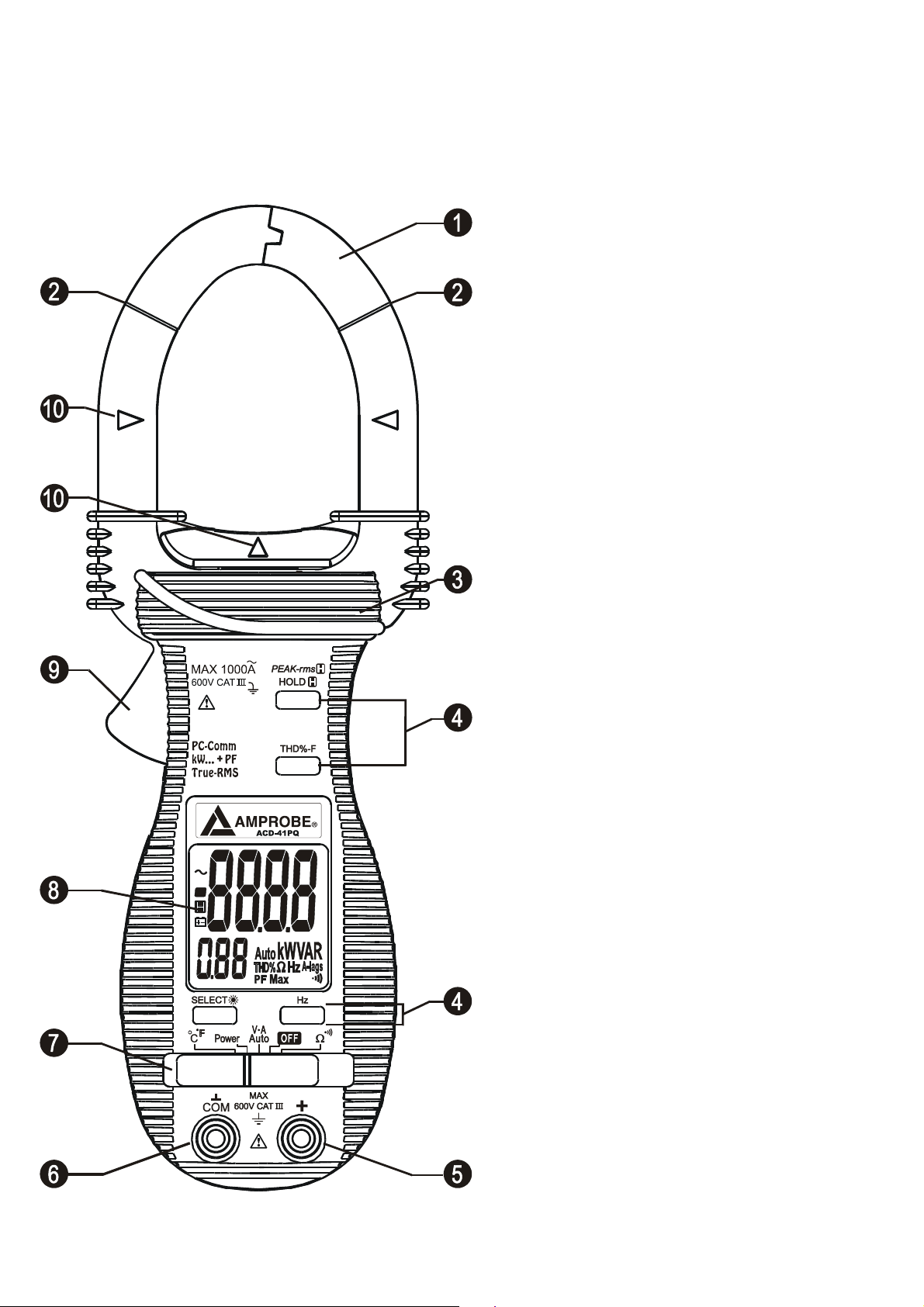
3) PRODUCT DESCRIPTION
This user's manual uses only representative model(s) for illustrations. Please refer
specification details for function availability to each model.
1) Transformer Clamp Jaws for AC
current magnetic field pick up
2) Jaw marking lines for ACA (& thus
Power) position error indication
3) Hand/Finger Barrier to indicate the
limits of safe access to the jaws during
current measurements
4) Push-buttons for special functions &
features
5) Input Jack for all functions EXCEPT
non-invasive ACA current (& thus
Power) function
6) Common (Ground reference) Input
Jack for all functions EXCEPT
non-invasive ACA current (& thus
Power) function
7) Slide-switch Selector to turn the
power ON/OFF and Select a function
8) LCD display
9) Jaw trigger for opening the
transformer clamp jaws
10) Jaw center Indicators, at where
best ACA (& thus Power) accuracy is
specified
4) OPERATION
4
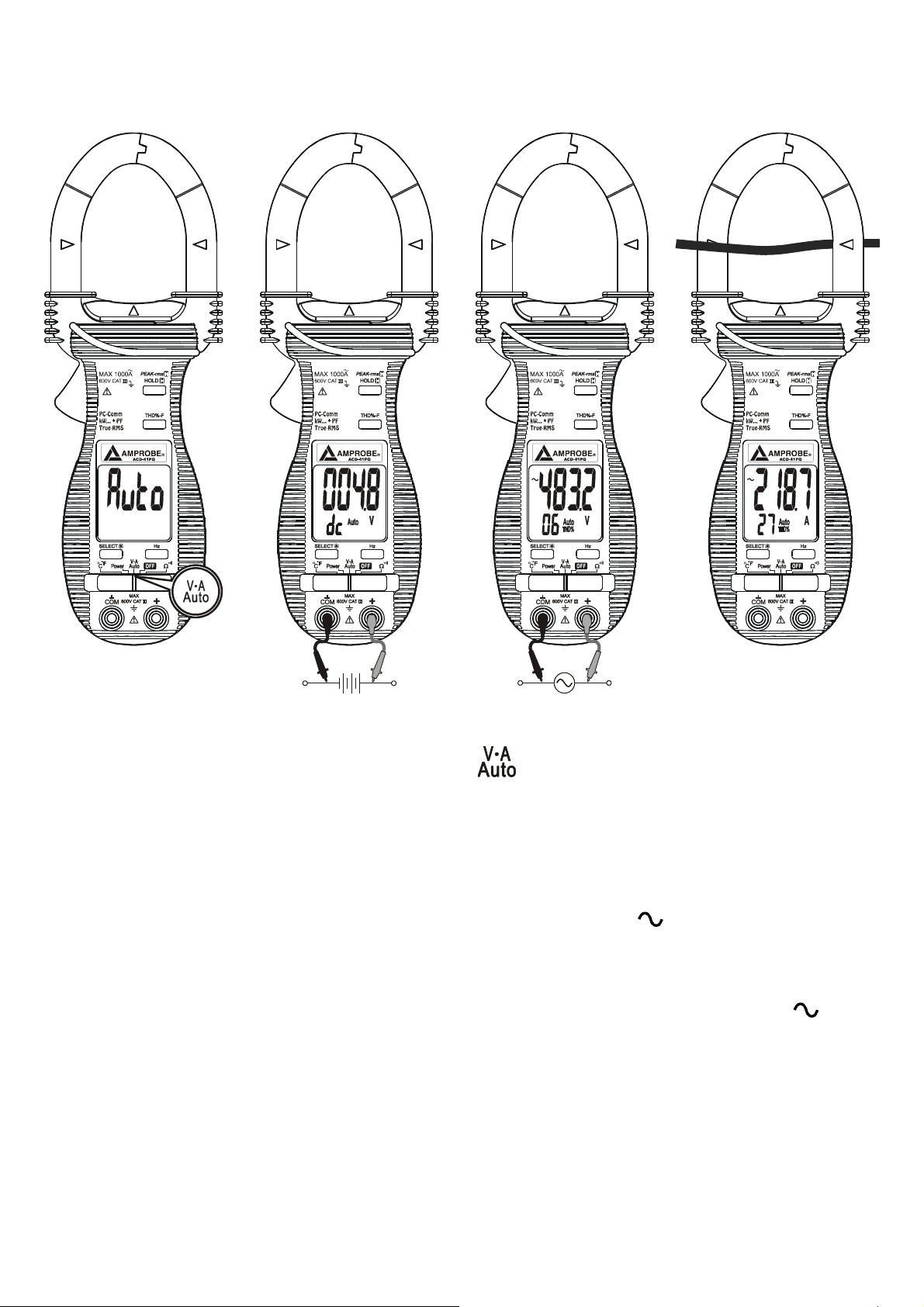
AutoVA
TM
function
Set the slide-switch function-selector to the position.
●With no input, the meter displays “Auto” when it is ready.
●With no ACA current input via the jaws but a voltage signal above the nominal
threshold of DC 2.4V or AC 30V (40Hz ~ 500Hz) up to the rated 600V is present on
V-COM terminals, the meter displays the voltage value in appropriate DC or AC,
whichever larger in peak magnitude. LCD annunciator “dc” or “
” turns on respectively.
●On the contrary, with no voltage signal present on V-COM terminals but a ACA current
signal above the nominal threshold of AC 1A (40Hz ~ 500Hz) up to the rated 1000A is
input via the jaws, the meter displays the ACA current value. LCD annunciator “
” turns
on accordingly.
●The Auto-VA feature stays at the auto-selected function as long as its signal remains
above the specified threshold. Press SELECT button momentarily to manually select
thru the functions ACA, ACV, DCV and then goes back to Auto-VA.
CAUTION
●For non-invasive ACA current measurements, press the jaw trigger and clamp the jaws
5
around only one single conductor of a circuit for load current measurement. Make sure
the jaws are completely closed, or else it will introduce measurement errors. Enclosing
more than one conductor of a circuit will result in differential current (like identifying
leakage current) measurement.
●Adjacent current-carrying devices such as transformers, motors and conductor wires
will affect measurement accuracy. Keep the jaws away from them as much as possible
to minimize influence.
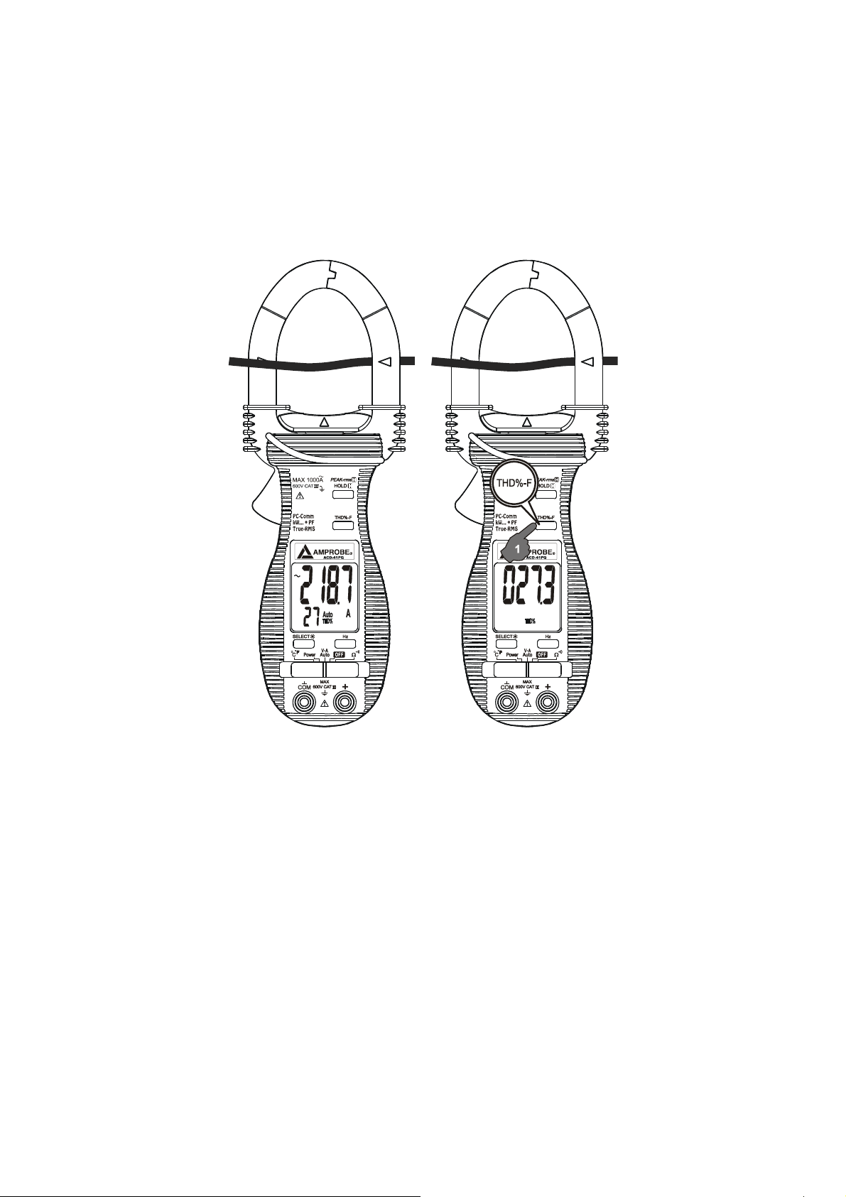
THD%-F Total Harmonic Distortion-Fundamental function (model ACD-41PQ only)
THD%-F = (Total Harmonics RMS / Fundamental RMS) x 100%
Total Harmonic Distortion - Fundamental (THD%-F) is the percentage ratio of the Total
Harmonics RMS value to the Fundamental RMS value of a voltage or current signal, and
is given by the above expression. An ideal sinusoidal waveform has a value of 0 THD%.
A badly distorted sinusoidal waveform may have a much higher THD% value of up to
several hundreds.
When the meter is in ACV or ACA function, THD%-F values up to 99 THD% will be
displayed in the secondary mini display automatically. Press THD%-F button
momentarily toggles THD% readings to main display to get full readings up to 999.9
THD%.
 Loading...