

Page 1

SLM Electronics #CSB0003
A Division of St. Louis Music, Inc
11880 Borman Dr Service Department
St. Louis, MO 63146 Phone 800 738 7563
Phone 314 569 0141 Fax 314 567 7278
November 6, 1997 Customer Service Bulletin
Units Affected:
SVT-2PROJ units serial numbered T2PJJ40001 through T2PJJ40042
SVT-2PROJ units serial numbered T2PJJ80001 through T2PJJ80010
SVT-CLJ units serial numbered TCLJJ40001 through TCLJJ40032
SVT-CLJ units serial numbered TCLJJ60001 through TCLJJ60002
SVT-CLJ units serial numbered TCLJJ90001 through TCLJJ90020
Note: A number of units in these serial number ranges have been factory modi fied to
corre ct the proble m. These units do not need to be modified in the field. They can be
identified by the presence of a “S tar Quality” label affixed to the outside of the shipping
carton adjacent to the serial number/Bar code label.
Conce rn:
AC mains fuse for filament transformer would fail p rematurely during normal operation when turning unit
on as a result of a design change to use IEC approved fuse beginning with 1/1/97 production. Replacement
with larger value fuse would solve false trip p ing p roblem but would not always provide adequate protection
against damage during severe fault condition.
Co rre cti ve Acti on :
Add two each 3A in-rush current limiters (ICL’s) that have been prepared with .187” Fast-on connectors
(SLM E part number 97-123-23) to the filament transformer p rimary circuit as follows:
1. Disconnect the AC power from the unit.
2. Remove lower chassis assembly from cabinet and view from bottom.
3. On the 07-319-xx AC termination PC board, remove blue and gray leads from tabs J17 and J18.
4. Add one 97-123-23 ICL assembly in series with the blue transformer lead and tab J17, and one
in series with the gray lead and J18 by attaching the female Fast-on connector of ICL to the tab
on the p rinted circuit board and the male Fast-on to transformer lead.
5. Secure the assembly with a cable tie to other AC wires so that no leads are touching other parts.
6. Replace the fuse (F2) with a T1.25A (SLM E part number 23-512-05).
7. Remove any fuse label so that “100VAC T1.25A” is visible on the printed circuit board.
8. Reassemble and check out unit for proper operation.
Page 2
Note: For best operation of ICLs do not rapidly turn the amp lifier off and on. These devices are selfheating and require a short time to cool and return to their protective, “ high resistance” st ate.
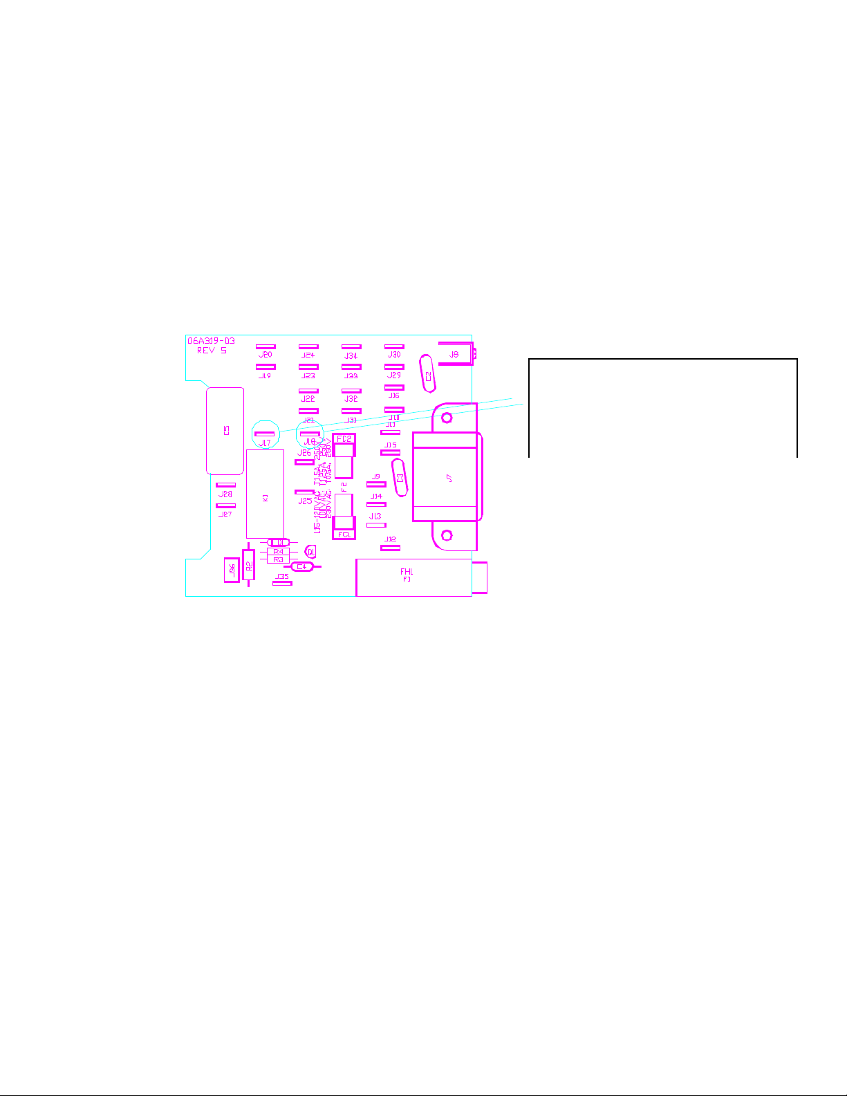
07-319-xx AC Termination board as viewed from inside lower chassis
Add one 97-123-23 ICL assembly in
series with J17 and the blue transformer
lead and one in series with J18 and the
gray transformer lead.
 Loading...