

Page 1

RB-108, RB-110, RB-112, RB-115, and RB-210
Bass Guitar Combo Amplifiers
Owner's Manual
Page 2
TABLE OF CONTENTS
What’s in the Box . . . . . . . . . . . . . . . . . . . . . . . . . . . . . . . . . . . . . . . . . . . . . . . . . . . . 2
Introduction . . . . . . . . . . . . . . . . . . . . . . . . . . . . . . . . . . . . . . . . . . . . . . . . . . . . . . . . . 2
Rocket Bass Series Features . . . . . . . . . . . . . . . . . . . . . . . . . . . . . . . . . . . . . . . . . . . 3
Top Panel Features . . . . . . . . . . . . . . . . . . . . . . . . . . . . . . . . . . . . . . . . . . . . . . . . . . . 4
Rear Panel Features . . . . . . . . . . . . . . . . . . . . . . . . . . . . . . . . . . . . . . . . . . . . . . . . . . 5
RB-108 Technical Specifications . . . . . . . . . . . . . . . . . . . . . . . . . . . . . . . . . . . . . . . . 6
RB-110 Technical Specifications . . . . . . . . . . . . . . . . . . . . . . . . . . . . . . . . . . . . . . . . 7
RB-112 Technical Specifications . . . . . . . . . . . . . . . . . . . . . . . . . . . . . . . . . . . . . . . . 8
RB-115 Technical Specifications . . . . . . . . . . . . . . . . . . . . . . . . . . . . . . . . . . . . . . . . 9
RB-210 Technical Specifications . . . . . . . . . . . . . . . . . . . . . . . . . . . . . . . . . . . . . . . 10
Warranty and Support . . . . . . . . . . . . . . . . . . . . . . . . . . . . . . . . . . . . . . . . . . . . . . . . 11
What’s in the Box
Rocket Bass Combo Series
RB-108, RB-110, RB-112, RB-115, or RB-210 Amplifier, Power Cable, Quick Start Guide.
Introduction
Designed from the ground up, with Ampeg’s industry standard tone and styling in mind, the all-new
Rocket Bass combos feature the legacy Ampeg preamp and tone stack circuits with the widest
range of classic Ampeg tones any Ampeg combo has ever offered. The new SGT™ (Super Grit
Technology) overdrive circuit gives you the warmth and grit of a monster SVT® stack, packed into a
lightweight combo that you can easily carry to any practice or performance.
Iconic black diamond vinyl, reminiscent of the most recorded bass amp of all time, the Ampeg B15,
wraps the most lightweight cabinets Ampeg has ever built, without sacrificing ground shaking lows
and classic Ampeg tone. Integrated DIs, effect loops, and aux in/phones out circuits provide the
ultimate tools for any rehearsal or gigging situation.
Like all Ampeg products, your Rocket Bass combo is designed by musicians and built using only
the best of components. Each combo is tested to confirm that it meets our specifications, and we
believe that each amp is the best that it can be.
In order to get the most out of your new combo, please fully read this Owner’s Manual, as well as
the Important Safety Instructions included with your Rocket Bass series amp, before you begin
playing.
Best of luck in all of your musical endeavors!
- And THANK YOU for choosing Ampeg! -
2
Page 3

Rocket Bass Series Features
• Superior Tone
• Legacy Ampeg preamp and tonestack circuits
• New SGT overdrive circuit
• Perfectly-matched Eminence
• Pro-Grade Flexibility
• Super lightweight construction
• Integrated DIs, effects loops, extension speaker outs*
• Aux in / headphone outs
• Iconic Styling
• Ampeg’s iconic black diamond vinyl
• Impact-resistant metal corners
• Rugged, braced enclosures
®
custom speakers*
Rocket Bass Combo Series
*Some features available on select models only.
3
Page 4
Top Panel Features
Rocket Bass Combo Series
3
4 5
6
1 2 7 9 10 11 128
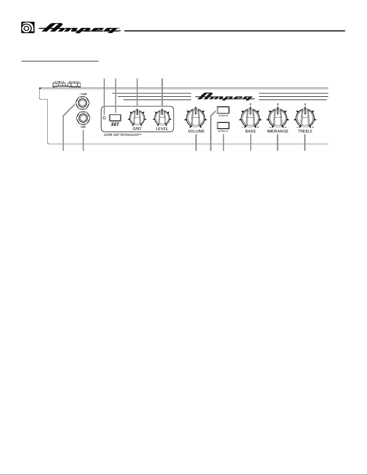
1. –15 dB INPUT: The attenuation of this 1/4”
input is suited for use with basses that have
active electronics or high-output pickups.
Connect here using a shielded instrument
cable.
2. 0 dB INPUT: The signal output from a
passive instrument may be connected to this
1/4” input. Connect here using a shielded
instrument cable.
3.
SGT
LED: This LED illuminates amber when
the SGT overdrive circuit is on.
4.
SGT
ON/OFF: Engage this switch to activate
the SGT overdrive circuit. This allows
for varying amounts of tube-like grit and
distortion.
5. GRIT: Use to adjust the amount of SGT
"grit." Turn the knob clockwise for a more
overdriven sound (RB-110, RB-112, RB-115,
RB-210).
6. LEVEL: Use to control the overall level of
the SGT overdrive circuit. Turn the knob
clockwise to increase the SGT level. (RB-110,
RB-112, RB-115, RB-210).
7. VOLUME: Use to control the amplifier's
overall output level. It affects the preamp
level fed to the Speaker and Phones outputs.
Use it wisely and turn down when making
connections, wearing headphones, or when
trying something new. This control does not
affect any signal coming into to the Aux Input
(14).
8. ULTRA HI: This switch, when engaged,
enhances the amount of high frequency
output with 5 dB boost at 8 kHz (RB-112,
RB-115, RB-210).
9. ULTRA LO: This switch, when engaged,
enhances the amount of low-end output with
a 1 dB boost at 40 Hz, and a 10 dB cut at
500 Hz (RB-112, RB-115, RB-210).
10. BASS: Use to adjust the low frequency level
of the amplifier. The low frequency output is
flat at the center, "0" knob position. Rotate
the control counter clockwise from 0 to
reduce the bass frequencies—or clockwise
from 0 to increase the bass frequencies.
See the following pages for Technical
Specifications.
11. MIDRANGE: Use to adjust the midrange
frequency level of the amplifier. The midrange
frequency level is flat at the center "0" knob
position. Rotate the control counter clockwise
for a "contoured" sound (more distant, less
midrange output), or clockwise for a sound
that really cuts through (increased midrange).
See the following pages for Technical
Specifications.
12. TREBLE: Use to adjust the high frequency
level of the amplifier. The high frequency level
is flat at the center "0" knob position. Rotate
the control counter clockwise from 0 to
reduce the treble frequencies—or clockwise
from 0 to increase the treble frequencies.
See the following pages for Technical
Specifications.
4
Page 5
Rocket Bass Combo Series
HORN
Top Panel Features
13
14 15 16
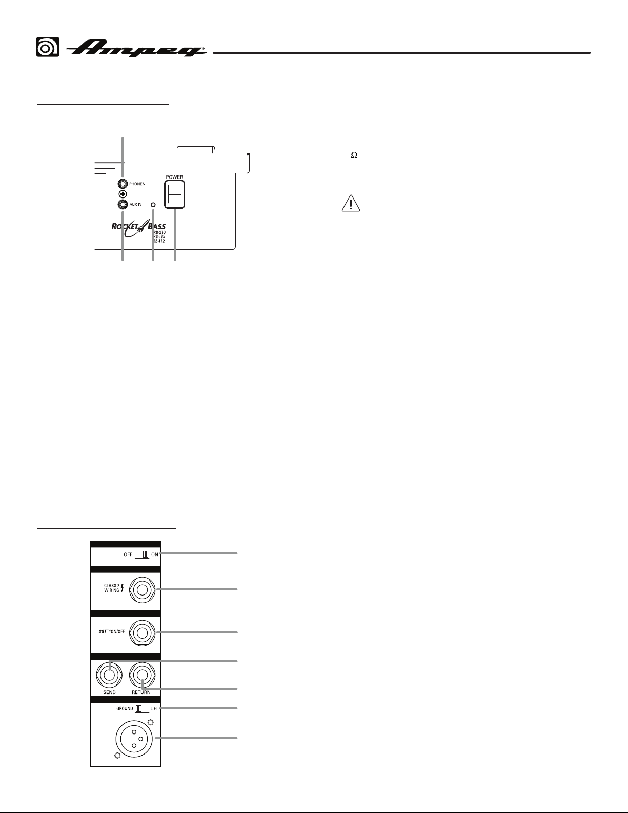
13. PHONES: Use this 1/8" TRS stereo output to
connect your headphones. The output here
is a mix of the line level signals reaching the
amplifier, as well as any incoming audio from
the Aux Input jack (14). Speaker output is
muted when Phones are connected.
14. AUX INPUT: The analog audio output from
a line level source, such as an MP3 player or
other music source, can be connected to this
1/8" input.
15. ON LED: This LED illuminates blue when the
amplifier's power is on.
17. Horn On/Off Switch: Turns the high
frequency horn on/off (RB-210 only).
18. EXT SPEAKER OUTPUT: Optionally, use
this 1/4" TS output jack to connect to an
8
extension speaker cabinet. The internal
speaker remains active when an extension
speaker is connected.
Use a non-shielded speaker cable with
1/4" TS ends to make the connections.
Do not use shielded instrument cables
as they may overheat.
19.
SGT
SWITCH: Optionally, connect a 1/4"
TS footswitch to this jack for remote on/off
control of the SGT circuit (RB-112, RB-115,
RB-210).
NOTE: A footswitch may be purchased at
your local Ampeg Dealer, or directly from
shop.ampeg.com.
20. EFFECTS LOOP SEND: Use a TS
(unbalanced) cable from this 1/4" output to
send a line level signal to an external effects
processor. The output here is affected by all
controls. Use the Effects Loop Return jack to
feed the returned processed signals back into
the power amplifier—see item 21 (RB-112,
RB-115, RB-210).
16. POWER SWITCH: Press the top of this switch
to turn on the overall system power, and press
the bottom of the switch to turn it off.
Rear Panel Features
17
EXT SPEAKER
SGT ™ SWITCH
EFFECTS LOOP
BALANCED DI OUT
18
19
20
21
22
23
21.
FFECTS LOOP RETURN: Use a TS
E
(unbalanced) cable into this 1/4" input to
return the processed line level output of an
external effects processor. The processor
could be fed by signals from the Effects
Loop Send—see item 20 (RB-112, RB-115,
RB-210).
GROUND / LIFT SWITCH: Toggle to Lift
22.
to disable the ground connection at the
Balanced DI Output jack if grounding hum
or noise is present – see item 23 (RB-110,
RB-112, RB-115, RB-210).
BALANCED DI OUT: Connect this post-EQ,
23.
post-SGT, mic level, balanced XLR output to
the balanced input of an external mixer or
recorder. In this configuration, you do not
need to mic the speaker cabinet in order to
add it to the main mix or to record (RB-110,
RB-112, RB-115, RB-210)
5
Page 6
RB-108 Technical Specifications
Rocket Bass Combo Series
RB-108
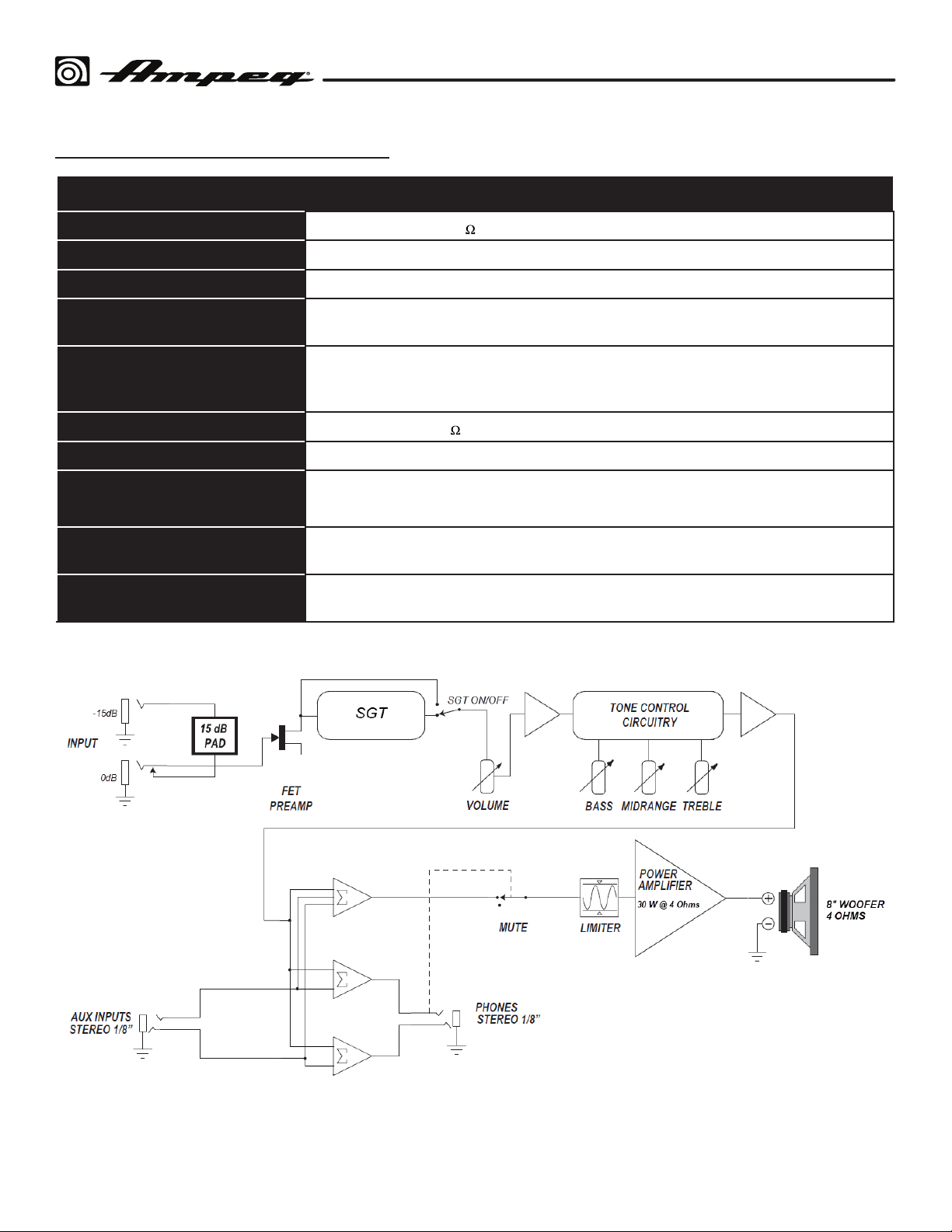
Output Power Rating
Signal-to-Noise Ratio
Maximum Gain @ 1 kHz
Input Impedance
Tone Controls
Speaker Specs
Maximum Operating Range
Power Requirements
Size (H x W x D)
Weight (Approximate)
30 Watts RMS @ 4
80 dB (20 Hz–20 kHz unweighted)
Input: 45 dB
Normal Input: 500k Ohms
-15dB Pad Input: 75k Ohms
Bass: +13/–21 dB @ 40 Hz
Mid: +16/–10 dB @ 500 Hz
reble: +12/–16 dB @ 4 kHz
T
1 x 8" speaker, 4
40° C ambient temperature, 93% relative humidity, up to 2000 m altitude
100–240V ~ 50-60 Hz, 45W Max
17 x 16.2 x 12 inches
433 x 411 x 306 mm
23 lbs
10.45 kg
All specifications subject to change.
10% THD+N
6
Page 7
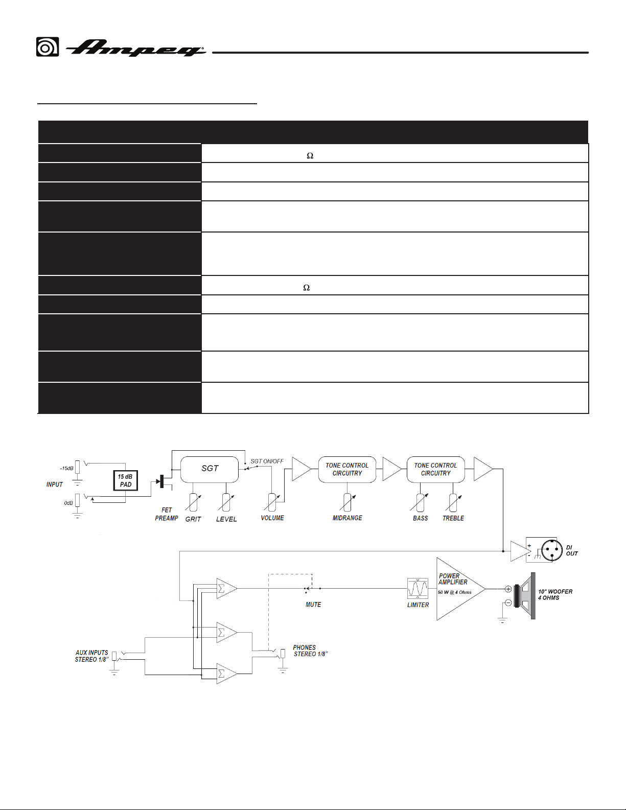
RB-110 Technical Specifications
Rocket Bass Combo Series
RB-110
Output Power Rating
Signal-to-Noise Ratio
Maximum Gain @ 1 kHz
Input Impedance
Tone Controls
Speaker Specs
Maximum Operating Range
Power Requirements
Size (H x W x D)
Weight (Approximate)
50 Watts RMS @ 4
84 dB (20 Hz–20 kHz unweighted)
Input: 48.5 dB
Normal Input: 1Meg Ohms
-15dB Pad Input: 75k Ohms
Bass: +14/–20 dB @ 40 Hz
Mid: +15/–10 dB @ 500 Hz
Treble: +12/–16 dB @ 4 k
1 x 10" speaker, 4
40° C ambient temperature, 93% relative humidity, up to 2000 m altitude
100-240V ~ 50-60 Hz, 70W Max
19 x 16.2 x 13 inches
481 x 411 x 330 mm
22.5 lbs
10.20 kg
All specifications subject to change.
10% THD+N
Hz
7
Page 8
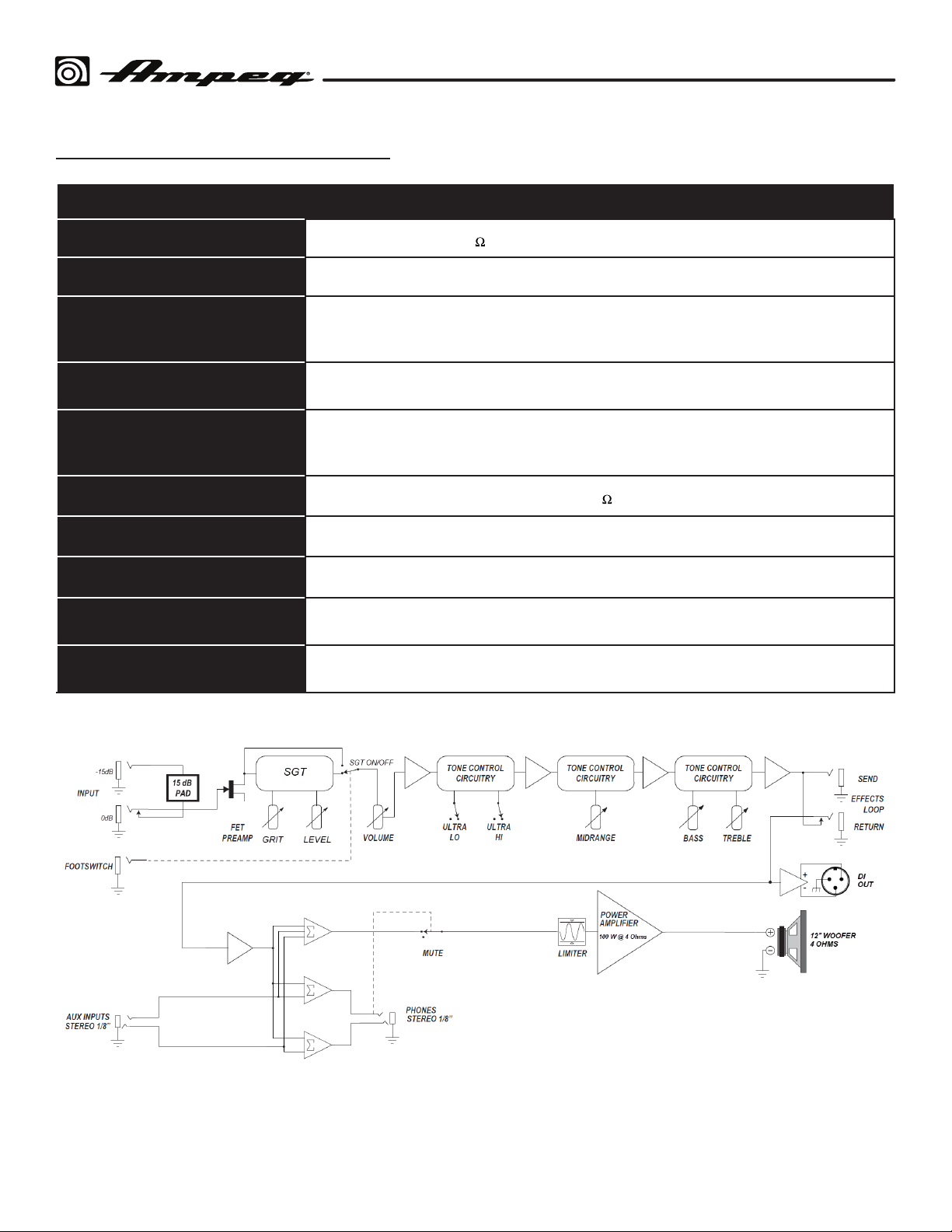
RB-112 Technical Specifications
Rocket Bass Combo Series
RB-112
Output Power Rating
Signal-to-Noise Ratio
Maximum Gain @ 1 kHz
Input Impedance
Tone Controls
Speaker Specs
Maximum Operating Range
Power Requirements
Size (H x W x D)
Weight (Approximate)
100 Watts RMS @ 4
80 dB (20 Hz–20 kHz unweighted)
Input: 48.5 dB
Aux Input: 33 dB
Effects Return: 29 dB
Normal Input: 1Meg Ohms
-15dB Pad Input: 75k Ohms
Bass: +14/–14 dB @ 40 Hz
Mid: +5/–11 dB @ 500 Hz
Treble: +15/–15 dB @ 4 kHz
1 x 12" custom Eminence speaker, 4
40° C ambient temperature, 93% relative humidity, up to 2000 m altitude
100–240V AC ~ 50-60 Hz, 150W Max
21.4 x 18.2 x 14.2 inches
543 x 462 x 360 mm
25.9 lbs
11.75 kg
10% THD+N
All specifications subject to change.
8
Page 9
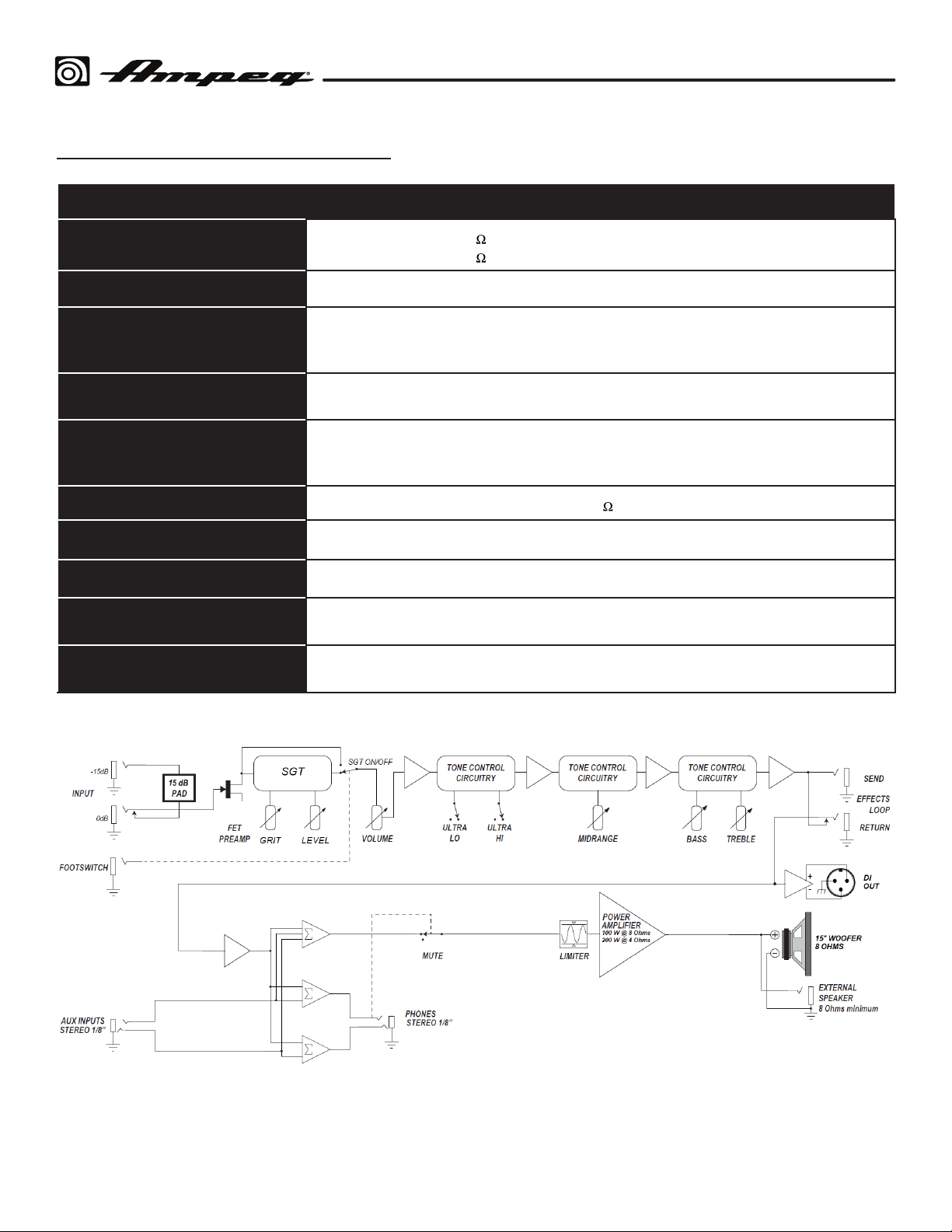
RB-115 Technical Specifications
Rocket Bass Combo Series
RB-115
Output Power Rating
Signal-to-Noise Ratio
Maximum Gain @ 1 kHz
Input Impedance
Tone Controls
Speaker Specs
Maximum Operating Range
Power Requirements
Size (H x W x D)
Weight (Approximate)
200 Watts RMS @ 4
100 Watts RMS @ 8 10% THD+N (with external speaker)
90 dB (20 Hz–20 kHz unweighted)
Input: 60 dB
Aux Input: 39 dB
Effects Return: 32 dB
Normal Input: 1Meg Ohms
-15dB Pad Input: 75k Ohms
Bass: +14/–14 dB @ 40 Hz
Mid: +5/–11 dB @ 500 Hz
T
reble: +16/–15 dB @ 4 kHz
1 x 15" custom Eminence speaker, 8
40° C ambient temperature, 93% relative humidity, up to 2000 m altitude
100–240V ~ 50-60 Hz, 280W Max
22.4 x 20.2 x 13.94 inches
570 x 513 x 354 mm
33.4 lbs
15.45 kg
3% THD+N (with external speaker)
All specifications subject to change.
9
Page 10
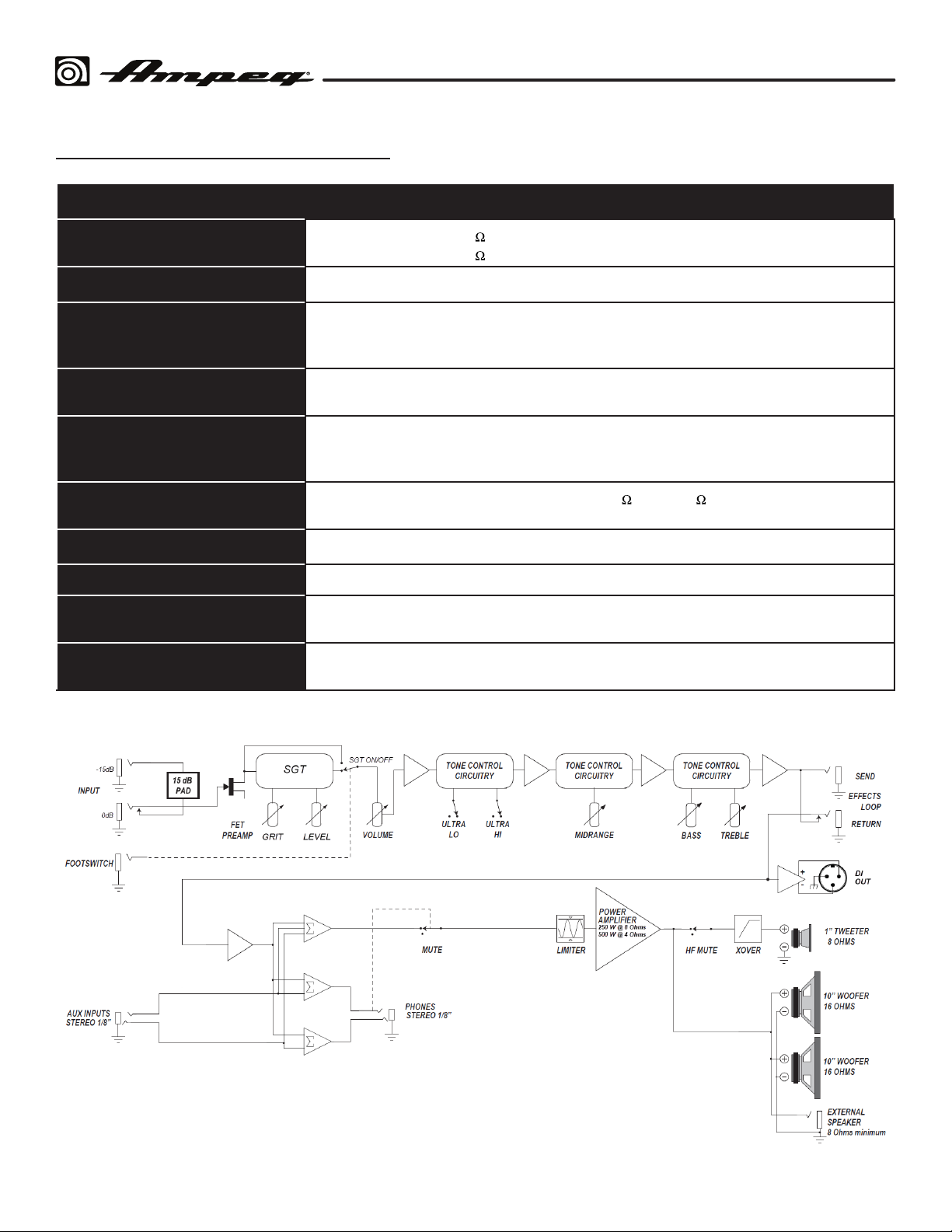
RB-210 Technical Specifications
Rocket Bass Combo Series
RB-210
Output Power Rating
Signal-to-Noise Ratio
Maximum Gain @ 1 kHz
Input Impedance
Tone Controls
Speaker Specs
Maximum Operating Range
Power Requirements
Size (H x W x D)
Weight (Approximate)
500 Watts RMS @ 4
250 Watts RMS @ 8 10% THD+N (with external speaker)
91 dB (20 Hz–20 kHz unweighted)
Input: 73 dB
Aux Input: 52 dB
Effects Return: 36 dB
Normal Input: 1Meg Ohms
-15dB Pad Input: 75k Ohms
Bass: +14/–14 dB @ 40 Hz
Mid: +5/–11 dB @ 500 Hz
reble: +16/–15 dB @ 4 kHz
T
2 x 10" custom Eminence speakers, 16
1 HF compression driver
40° C ambient temperature, 93% relative humidity, up to 2000 m altitude
100–240V ~ 50-60 Hz, 600W Max
25.75 in x 20.2 in x 13.94 inches
654 x 513 x 354 mm
38 lbs
17.7 kg
3% THD+N (with external speaker)
each (8 in parallel)
All specifications subject to change.
10
Page 11

Warranty and Support
Visit WWW.AMPEG.COM to...
(1) ...identify WARRANTY coverage provided in your local market. Please keep
your sales receipt in a safe place.
(2) ...REGISTER your product.
(3) ...CONTACT Technical Support, or call 818-575-3600.
www.ampeg.com
26580 Agoura Road, Calabasas, CA 91302-1921 USA
© 2021 Yamaha Guitar Group, Inc. All rights reserved.
Ampeg, the Ampeg logo, SGT, Super Grit Technology, and SVT are trademarks or registered trademarks of Yamaha Guitar
Group, Inc. in the U.S. and/or other jurisdictions. Eminence is a registered trademark of Eminence Speaker, LLC.
Yamaha Guitar Group, Inc.
Rev. A
Serial Number: _______________________________
 Loading...