

Page 1
Version: 2, March 2019
Designed and manufactured in Australia by Ampcontrol Pty Ltd
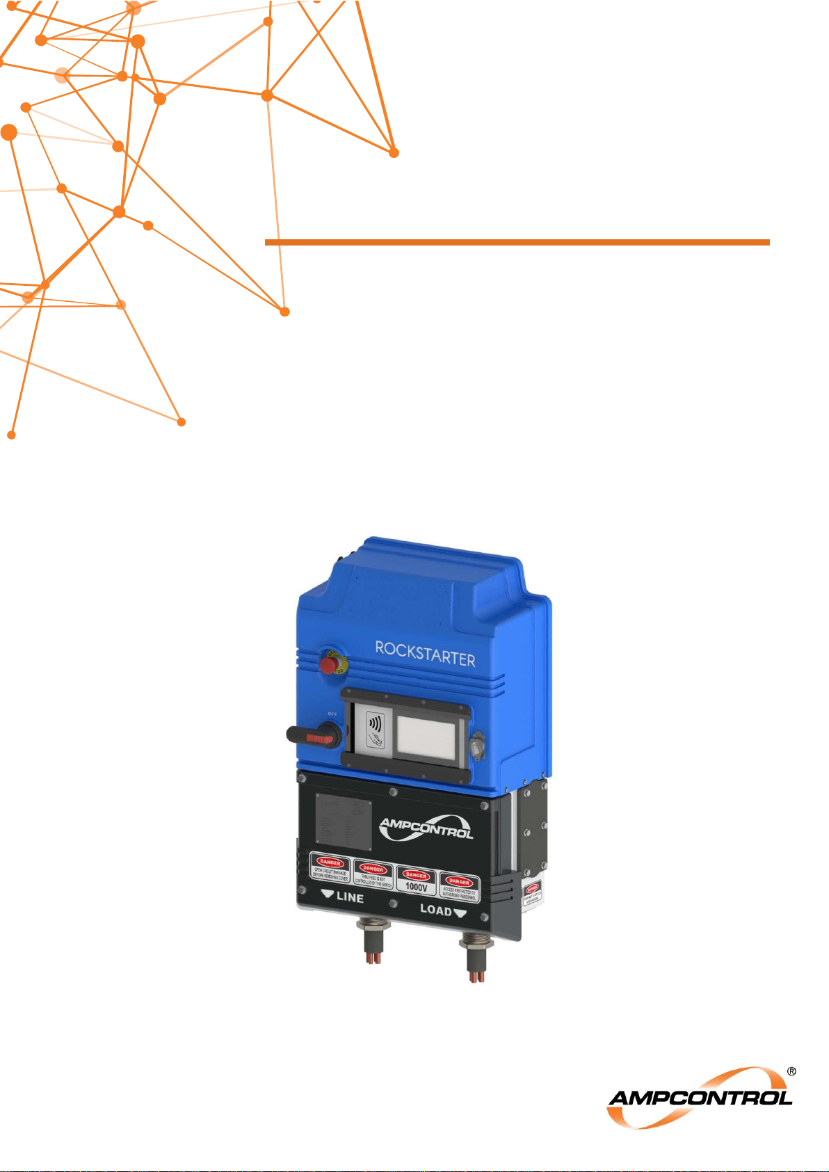
ROCKSTARTER
Multifunction Outlet Starter
User Manual
Page 2
Ampcontrol Pty Ltd – ABN 28 000 915 542
ROCKSTARTER USER MANUAL
MAG-222 Version 2 – MARCH/19
Uncontrolled Copy - Refer to Ampcontrol Website for Latest Version
Page 2 of 127
APPROVED FOR EXTERNAL DISTRIBUTION
– PROPERTY OF AMPCONTROL PTY LTD
– NOT TO BE REPRODUCED IN PART
WARNING!
The warning symbol highlights a potential risk of injury or death.
Please share these warnings with other operators.
CAUTION!
The caution symbol highlights a potential risk of damage to
equipment.
Please share these cautions with other operators.
NOTE
The note symbol highlights key information.
Please share these notes with other operators.
ENVIRO
The enviro (environmental) symbol highlights areas which may have an
impact on the surrounding fauna and/or flora.
Page 3
Ampcontrol Pty Ltd – ABN 28 000 915 542
ROCKSTARTER USER MANUAL
MAG-222 Version 2 – MARCH/19
Uncontrolled Copy - Refer to Ampcontrol Website for Latest Version
Page 3 of 127
APPROVED FOR EXTERNAL DISTRIBUTION
– PROPERTY OF AMPCONTROL PTY LTD
– NOT TO BE REPRODUCED IN PART
Copyright Notice
The Ampcontrol Rockstarter described in this document is the property of AMPCONTROL PTY LTD. It is
furnished under a license agreement and is to be used only in accordance with the terms of the
agreement.
No part of the hardware or documentation may be reproduced, transmitted, transcribed, stored in a
retrieval system, or translated into any language or computer language, in any form or by any means,
without prior written permission of AMPCONTROL PTY LTD.
Disclaimer
While every effort has been made to assure the accuracy and clarity of this document, AMPCONTROL
PTY LTD assumes no liability resulting from any omissions in this document, or from misuse of the
information obtained herein. The information in this document has been carefully checked and is
believed to be entirely reliable with all of the necessary information included. AMPCONTROL PTY LTD
reserves the right to make changes to any products described herein to improve reliability, function, or
design, and reserves the right to revise this document and make changes from time to time in content
hereof with no obligation to notify any persons of revisions or changes. AMPCONTROL PTY LTD does
not assume any liability arising out of the application or any use of any product or circuit described
herein; neither does it convey license under its patent rights or the rights of others.
Before You Begin
Thank you for purchasing the Ampcontrol Rockstarter.
WARNING!
In the interests of safety and correct equipment operation, please
take the time to read and understand the content in this manual.
Ampcontrol Contact Details
7 Billbrooke Close, Cameron Park, NSW, 2285
P +61 1300 267 373 | F +61 2 4903 4888
EMAIL: [email protected]
WEB: ampcontrolgroup.com
Page 4
Ampcontrol Pty Ltd – ABN 28 000 915 542
ROCKSTARTER USER MANUAL
MAG-222 Version 2 – MARCH/19
Uncontrolled Copy - Refer to Ampcontrol Website for Latest Version
Page 4 of 127
APPROVED FOR EXTERNAL DISTRIBUTION
– PROPERTY OF AMPCONTROL PTY LTD
– NOT TO BE REPRODUCED IN PART
TABLE OF CONTENTS
1 SAFETY AND OTHER WARNINGS ................................................................ 11
Safe Use of Equipment ............................................................................ 11
Supplementary Documentation ................................................................ 11
Requirements for Safe Operation............................................................. 12
2 RECEIVING AND STORAGE .......................................................................... 13
Receiving ................................................................................................. 13
Inspection ................................................................................................ 13
Transportation.......................................................................................... 13
Storage after Delivery .............................................................................. 14
Unpacking of Equipment .......................................................................... 14
3 PRODUCT DESCRIPTION ............................................................................. 15
Overview .................................................................................................. 15
Features .................................................................................................. 15
Application ............................................................................................... 15
Configuration Examples ........................................................................... 17
Arc Fault Mitigation .................................................................................. 18
4 INSTALLATION ............................................................................................... 19
General Warnings .................................................................................... 19
Mandatory Installation Practices .............................................................. 19
Mechanical Installation Information .......................................................... 20
Electrical Installation Information ............................................................. 30
5 COMMISSIONING .......................................................................................... 35
Earth Leakage ......................................................................................... 35
Earth Continuity ....................................................................................... 35
Earth Fault Lockout .................................................................................. 35
Insulation Test (High Voltage) .................................................................. 36
Main Contactor Fail .................................................................................. 36
Voltage Measurement .............................................................................. 36
Load Connection Module (LCM) .............................................................. 36
Pump Protection Test .............................................................................. 36
Fan Protection Test ................................................................................. 36
Remote Stop Test .................................................................................. 37
Remote Start Test .................................................................................. 37
Emergency Stop .................................................................................... 37
6 PRODUCT OPERATION ................................................................................. 38
Interfacing Elements ................................................................................ 38
Page 5
Ampcontrol Pty Ltd – ABN 28 000 915 542
ROCKSTARTER USER MANUAL
MAG-222 Version 2 – MARCH/19
Uncontrolled Copy - Refer to Ampcontrol Website for Latest Version
Page 5 of 127
APPROVED FOR EXTERNAL DISTRIBUTION
– PROPERTY OF AMPCONTROL PTY LTD
– NOT TO BE REPRODUCED IN PART
Outlet Starting .......................................................................................... 51
Outlet Resets ........................................................................................... 51
Internal Trips ............................................................................................ 52
Event Log ................................................................................................ 52
Time and date .......................................................................................... 54
Modbus TCP ............................................................................................ 54
Remote Desktop Access .......................................................................... 54
7 OUTLET CONTROL ........................................................................................ 55
Outlet Configuration ................................................................................. 55
Fan Control Mode .................................................................................... 57
Pump Control Mode – (Anti Snore Mode) ................................................ 60
8 TOUCH POTENTIAL PROTECTION FUNCTIONS ......................................... 64
Earth Leakage ......................................................................................... 64
Earth Continuity ....................................................................................... 65
Earth Fault Lockout .................................................................................. 69
Main Contactor Protection ....................................................................... 70
9 LOAD RELATED PROTECTION FUNCTIONS ............................................... 74
Inverse Time Protection ........................................................................... 74
Short Circuit ............................................................................................. 79
Under Voltage .......................................................................................... 81
Current Balance ....................................................................................... 81
Under Current .......................................................................................... 82
10 SERVICE, MAINTENANCE & DISPOSAL ..................................................... 83
Equipment Service ................................................................................. 83
Equipment Maintenance ........................................................................ 83
Disposal ................................................................................................. 84
11 ACCESSORIES & SPARE PARTS ............................................................... 85
Accessories ........................................................................................... 85
Spare Parts ............................................................................................ 89
12 SPECIFICATIONS ........................................................................................ 93
13 EQUIPMENT LIST ........................................................................................ 95
Rockstarter & Accessories ..................................................................... 95
Rockstarter Spares ................................................................................ 96
APPENDIX A: PROTECTION ELEMENT LOAD CURRENT TABLES ................ 98
A1: Protection Module Full Load Current Table ............................................. 98
A2: Protection Module TMS Table ............................................................... 100
APPENDIX B: ROCKSTARTER MODBUS TCP .............................................. 102
Page 6

Ampcontrol Pty Ltd – ABN 28 000 915 542
ROCKSTARTER USER MANUAL
MAG-222 Version 2 – MARCH/19
Uncontrolled Copy - Refer to Ampcontrol Website for Latest Version
Page 6 of 127
APPROVED FOR EXTERNAL DISTRIBUTION
– PROPERTY OF AMPCONTROL PTY LTD
– NOT TO BE REPRODUCED IN PART
B1 Outlet Control Registers ......................................................................... 102
B2 Outlet Live Data ...................................................................................... 102
B3 UI Live Data – Fan Mode ........................................................................ 106
B4 UI Live Data – Pump Mode..................................................................... 107
B5 UI Live Data – Outlet Mode .................................................................... 107
B6 UI Live Data – Common ......................................................................... 108
B7 Outlet Parameters .................................................................................. 109
B9 RKS Load Parameters – Diode Mode ..................................................... 109
B10 RKS General Parameters – Diode Mode .............................................. 115
B11 RKS Load Parameters – LCM Mode .................................................... 119
B12 RKS General Parameters – LCM Mode ................................................ 120
APPENDIX C: HMI REPLACEMENT................................................................ 122
APPENDIX D: RFID ACCESS FORM .............................................................. 124
APPENDIX E: DRAWINGS .............................................................................. 125
Page 7

Ampcontrol Pty Ltd – ABN 28 000 915 542
ROCKSTARTER USER MANUAL
MAG-222 Version 2 – MARCH/19
Uncontrolled Copy - Refer to Ampcontrol Website for Latest Version
Page 7 of 127
APPROVED FOR EXTERNAL DISTRIBUTION
– PROPERTY OF AMPCONTROL PTY LTD
– NOT TO BE REPRODUCED IN PART
TABLE OF FIGURES
Figure 1: Strapping Considerations ........................................................................................................ 13
Figure 2: Rockstarter Overview – Single Rockstarter.............................................................................. 16
Figure 3: Rockstarter Overview – Two Rockstarters with one incoming feed .......................................... 17
Figure 4: Rockstarter Overview – Four Rockstarters with two incoming feeds ........................................ 17
Figure 5: Example of Rockstarter Label .................................................................................................. 18
Figure 6: Rockstarter Dimensions (mm) ................................................................................................. 20
Figure 7: Rockstarter Lifting Adaptor ...................................................................................................... 21
Figure 8: Rockstarter Wall Bracket Mount .............................................................................................. 22
Figure 9: Mounting Bracket Clamps ........................................................................................................ 22
Figure 10: Rockstarter Terminal Compartment Cover Overview ............................................................. 23
Figure 11: Rockstarter Adaptor Plate (60A pictured) .............................................................................. 24
Figure 12: Dual Gland J-Box .................................................................................................................. 25
Figure 13: Dual Incomer Termination ..................................................................................................... 26
Figure 14: Through Feed – with (left) & without (right) cover .................................................................. 27
Figure 15: Ethernet & Terminal I/O Connector ........................................................................................ 27
Figure 16: Load Connection Module (LCM) (mm) ................................................................................... 28
Figure 17: Electrical Connection Diagram ............................................................................................... 30
Figure 18: Incoming Pilot – Terminations ................................................................................................ 31
Figure 19: Incoming Pilot – Through Terminations ................................................................................. 31
Figure 20: Outgoing Pilot – Terminations ................................................................................................ 32
Figure 21: Remote Stop/Start ................................................................................................................. 33
Figure 22: Load Connection Module (LCM) – Connection Diagram ........................................................ 33
Figure 23: Control Supply Termination ................................................................................................... 34
Figure 24: Rockstarter UI Interface ......................................................................................................... 38
Figure 25: Rockstarter UI – Home Screen .............................................................................................. 39
Figure 26: Rockstarter UI – Testing Screen ............................................................................................ 43
Figure 27: Rockstarter UI – Outlet Test System ...................................................................................... 44
Figure 28: Rockstarter UI – Status Screen ................................ ............................................................. 45
Figure 29: Rockstarter UI – SETUP Page ............................................................................................... 48
Figure 30: Rockstarter Lighting ............................................................................................................... 50
Figure 31: Rockstarter UI – Mode Control .............................................................................................. 56
Figure 32: Starting Options - Post Blast Start Enabled, Remote Start Disabled ...................................... 59
Figure 33: Starting Options - Post Blast Start and Delayed Start Enabled, Remote Start Disabled ......... 60
Figure 34: Starting Options – Pump Mode .............................................................................................. 63
Figure 35: Starting Options - Normal Mode ............................................................................................ 68
Figure 36: Rockstarter Mounting Frame C/W Bolts – PN: 177190 .......................................................... 85
Figure 37: Rockstarter Mounting Bar Kit – PN: 177191 .......................................................................... 85
Figure 38: Rockstarter Adaptor Plates - 60A left (PN: 179292) & 150A right (PN: 181811) .................... 86
Figure 39: Through Feed Kit – 181441 ................................................................................................... 86
Figure 40: Dual Gland Junction Box ....................................................................................................... 87
Figure 41: Dual Incomer Termination ..................................................................................................... 88
Figure 42: Rockstarter Gland Plate & Feed Through Kits ................................................................ ....... 89
Page 8

Ampcontrol Pty Ltd – ABN 28 000 915 542
ROCKSTARTER USER MANUAL
MAG-222 Version 2 – MARCH/19
Uncontrolled Copy - Refer to Ampcontrol Website for Latest Version
Page 8 of 127
APPROVED FOR EXTERNAL DISTRIBUTION
– PROPERTY OF AMPCONTROL PTY LTD
– NOT TO BE REPRODUCED IN PART
Figure 43: Rockstarter Terminal Cover Kit .............................................................................................. 90
Figure 44: Rockstarter Secondary Covers .............................................................................................. 91
Figure 45: Rockstarter Capacitive Touch Panel Kit ................................................................................. 92
Figure 46: Replacing the Display Glass and Digitiser ........................................................................... 122
Page 9

Ampcontrol Pty Ltd – ABN 28 000 915 542
ROCKSTARTER USER MANUAL
MAG-222 Version 2 – MARCH/19
Uncontrolled Copy - Refer to Ampcontrol Website for Latest Version
Page 9 of 127
APPROVED FOR EXTERNAL DISTRIBUTION
– PROPERTY OF AMPCONTROL PTY LTD
– NOT TO BE REPRODUCED IN PART
TABLE OF TABLES
Table 1: Rockstarter Dimensions ............................................................................................................ 20
Table 2: Terminal I/O Connector Pinout.................................................................................................. 27
Table 3: LCM Pinout ............................................................................................................................... 29
Table 4: Outlet State............................................................................................................................... 39
Table 5: Outlet Control ........................................................................................................................... 39
Table 6: Outlet Status Icons ................................................................................................................... 40
Table 7: Trip Messages .......................................................................................................................... 41
Table 8: OTS Status Symbols ................................................................................................................ 45
Table 9: Status Page Overview .............................................................................................................. 46
Table 10: Rockstarter Lighting Overview ................................................................................................ 50
Table 11: Event Log Entry Types............................................................................................................ 52
Table 12: Fan Protection – Configuration Settings .................................................................................. 58
Table 13: Rockstarter Burp Timing Mode ............................................................................................... 58
Table 14: Fan Incremental Timing Mode ................................................................................................ 59
Table 15: Pump Protection – Configuration Settings............................................................................... 61
Table 16: Rockstarter Pump Sleep Timing Mode .................................................................................... 61
Table 17: Pump Incremental Timing Mode ............................................................................................. 62
Table 18: Earth Leakage Trip Characteristics ......................................................................................... 64
Table 19: Earth Leakage CT Failure Trip Characteristics ....................................................................... 65
Table 20: Earth Continuity Series Trip Characteristics ............................................................................ 66
Table 21: Earth Continuity Shunt Trip Characteristics ............................................................................. 67
Table 22: Earth Fault Lockout Trip Characteristics ................................................................................. 69
Table 23: EFLO Trip Threshold .............................................................................................................. 70
Table 24: Voltage Detection Trip Characteristics .................................................................................... 70
Table 25: Frozen Contactor Trip Characteristics ..................................................................................... 71
Table 26: Contactor Close Fail Trip Characteristics ................................................................................ 72
Table 27: External Open Trip Characteristic ........................................................................................... 72
Table 28: Coil Voltage Detection Trip Characteristics ............................................................................. 73
Table 29: Over Current Trip Characteristics ........................................................................................... 75
Table 30: Motor Overload Trip Characteristics ........................................................................................ 76
Table 31: Short Circuit Trip Characteristics ............................................................................................ 79
Table 32: Under Voltage Trip Characteristics ......................................................................................... 81
Table 33: Current Balance Trip Characteristics ...................................................................................... 81
Table 34: Under Current Trip Characteristics ......................................................................................... 82
Page 10

Ampcontrol Pty Ltd – ABN 28 000 915 542
ROCKSTARTER USER MANUAL
MAG-222 Version 2 – MARCH/19
Uncontrolled Copy - Refer to Ampcontrol Website for Latest Version
Page 10 of 127
APPROVED FOR EXTERNAL DISTRIBUTION
– PROPERTY OF AMPCONTROL PTY LTD
– NOT TO BE REPRODUCED IN PART
DEFINITIONS
Term
Definition
CB
Circuit Breaker
CCM
Cable Connection Module
EC
Earth Continuity
EFLO
Earth Fault Lockout
EL
Earth Leakage
ELV
Extra Low Voltage
EMF
Electro-Motive Force
FC
Frozen Contactor
FLC
Full Load Current
Healthy
A state in which nothing should trip during the transition of the
state under test
HMI
Human Machine Interface
LCM
Load Connection Module
LOV
Loss of Vacuum
MC
Main Contactor
MEM
Main Electronics Module
OL
Overload
OTS
Outlet Test System
Outlet
The interface that sits on the load side of the Main Contactor
Rockstarter
Integrated starter with AS/NZS 2081 protection for underground
hard rock mines
RTD
Resistive Termination Device
Running
Main contactor closed and main contactor auxiliary indication in
correspondence with the main contactors state (i.e. indicating
that the main contactor is closed).
SC
Short Circuit
Start
A sequence beginning with a start command being issues from
the PLC, the completion of several outlet pre-energising checks
leading up to the closing of the main contactor
Stopped
Main contactor open and main contactor auxiliary indication in
correspondence with the main contactor state (i.e. indicating that
the main contactor is closed).
Trip
A fault condition which requires the opening of the main
contactor or the circuit breaker (fault dependent) to clear the
fault, or prevents the closing of the main contactor or circuit
breaker
TXF
Transformer
UC
Under current
UV
Under Voltage
Page 11
Ampcontrol Pty Ltd – ABN 28 000 915 542
ROCKSTARTER USER MANUAL
MAG-222 Version 2 – MARCH/19
Uncontrolled Copy - Refer to Ampcontrol Website for Latest Version
Page 11 of 127
APPROVED FOR EXTERNAL DISTRIBUTION
– PROPERTY OF AMPCONTROL PTY LTD
– NOT TO BE REPRODUCED IN PART
1 SAFETY AND OTHER WARNINGS
For safety reasons, the Rockstarter must be installed, operated and serviced only by competent
personnel. Please read and understand this instruction manual completely before installing, operating or
servicing this equipment. Failure to install or operate this equipment in accordance with the instructions
contained in this manual may create hazardous operating conditions.
Safe Use of Equipment
The equipment supplied has been designed and manufactured to ensure safe operation. The equipment
must only be used within the design parameters.
The instructions within this manual must be observed as an aid towards achieving the safest possible
installation.
Persons responsible for installation, maintenance, or operation, must observe the following
instructions:
Changes to Equipment
Changes in the design and modifications to the equipment are not permitted. Unauthorised changes
made to the hardware or operating firmware will void the manufacturer's warranty, and may
compromise the integrity of the system into which it is installed and other connected equipment.
Equipment Knowledge
Experience with, or understanding of, this equipment is essential for the safe installation and removal of
the equipment. Therefore, please read and understand this manual prior to use. Competency based
training courses are recommended and are available on request.
Manual Handling
Precautions have been taken to ensure all equipment is safe to handle and free from sharp edges.
However, care should always be taken when handling enclosures and gloves should be worn.
Installation
Correct operation and safety depend on the Rockstarter and associated equipment being installed and
configured correctly. Mechanical and or electrical installation and maintenance of plant and equipment
must only be carried out by appropriately qualified personnel and must be tested thoroughly prior to
operation.
Operation
As safety depends on the Rockstarter functioning correctly it is highly recommended that all safety
functions of the Rockstarter be periodically tested to ensure correct operation.
Supplementary Documentation
The Rockstarter’s User Manual is expected to be read in conjunction with the following documentation:
MAG-196 OTS User Manual
MAG-199 OTS Application User Manual
MAG-204 OTS Dashboard User Manual
Page 12

Ampcontrol Pty Ltd – ABN 28 000 915 542
ROCKSTARTER USER MANUAL
MAG-222 Version 2 – MARCH/19
Uncontrolled Copy - Refer to Ampcontrol Website for Latest Version
Page 12 of 127
APPROVED FOR EXTERNAL DISTRIBUTION
– PROPERTY OF AMPCONTROL PTY LTD
– NOT TO BE REPRODUCED IN PART
Requirements for Safe Operation
All settings must be implemented in accordance with the user’s fault and touch potential control
studies.
Upstream protection must be implemented in accordance with the user’s fault and touch potential
control studies.
The terminal compartment cover must not be removed unless the Rockstarter’s circuit breaker is
open.
Through Feed gland plates must not be removed unless the Rockstarter has been isolated
upstream.
The internal covers must not be removed unless the Rockstarter has been isolated upstream.
The internal covers must be replaced after termination work has been completed and before
upstream isolation is removed.
Upstream isolation must be carried out in accordance with user’s risk assessments and operating
procedures.
All requirements for safe operation should be integrated into the user’s own work procedures.
All gland plates and covers must be installed when in operation.
Gland plates and covers must maintain the Rockstarters IP65 rating, we recommend using
Ampcontrol type tested gland plates and covers.
Earthing must be in compliance with all regulations that the installation is subject to.
Users must periodically confirm the correct operation of E-stop as per their risk assessment.
Use certified and appropriately rated lifting equipment for all manual handling.
The Rockstarter must be installed, operated and serviced only by authorised and competent
personnel.
The user is responsible for implementing a change management strategy to ensure all settings
are configured in compliance with site protection and touch potential studies.
The through feed kit must only be used in conjunction with the Ampcontrol designed mounting
bar.
The Rockstarter is not designed for use in explosive atmospheres.
Do not operate in direct sunlight.
Do not operate the Rockstarter outside of its electrical or mechanical ratings.
The Rockstarter is designed for underground or indoor use.
Page 13
Ampcontrol Pty Ltd – ABN 28 000 915 542
ROCKSTARTER USER MANUAL
MAG-222 Version 2 – MARCH/19
Uncontrolled Copy - Refer to Ampcontrol Website for Latest Version
Page 13 of 127
APPROVED FOR EXTERNAL DISTRIBUTION
– PROPERTY OF AMPCONTROL PTY LTD
– NOT TO BE REPRODUCED IN PART
2 RECEIVING AND STORAGE
Receiving
All possible precautions are taken to protect the equipment against damage during shipment; however,
before accepting delivery, check all items against the packing list. If there is evidence of physical
damage or missing items please notify Ampcontrol immediately.
In the case of any discrepancies to the packing list. Keep a record of any claims and correspondence.
Photographs are recommended.
Where practicable do not remove protective covers prior to installation unless there are indications of
damage. Boxes opened for inspection and inventory should be carefully repacked to ensure protection of
the contents or else the parts should be packaged and stored in a safe place. Examine all packing
boxes, wrappings and covers for items attached to them, retain and store any approval documentation
for your safety file as applicable prior to wrapping being discarded.
Inspection
Equipment that is found to be damaged or has been modified away from its published specification must
not be used. Please contact Ampcontrol if the equipment is suspected to be different than that ordered or
if it does not match the published specifications.
Transportation
Ensure the Rockstarter is appropriately secured during transportation, ideally the Rockstarter should be
installed on the mounting frame for additional protection.
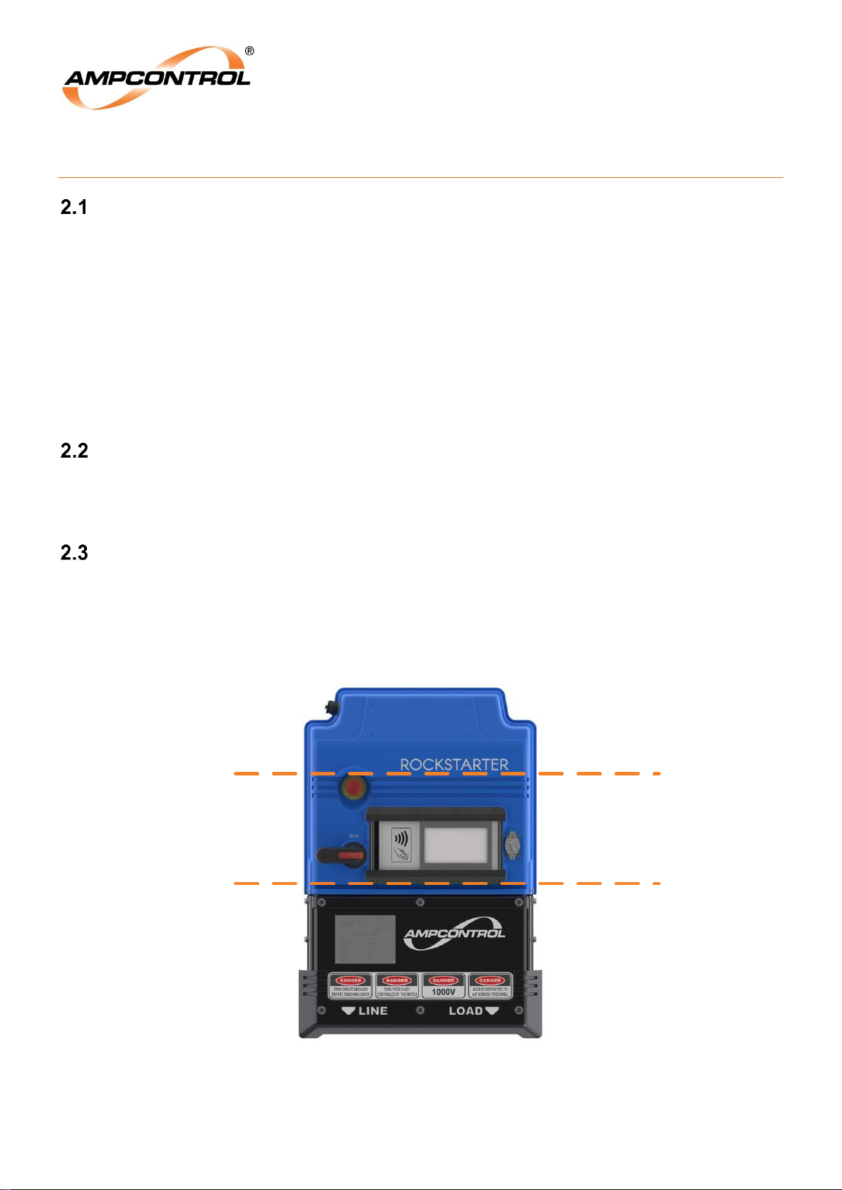
Care must be taken when strapping the Rockstarter. Avoid strapping over the Emergency Stop Switch,
HMI, CB handle, and earth stud. Avoid strapping over any sharp or protruding parts.
Avoid strapping
between these
lines
Avoid strapping over
earth stud
Figure 1: Strapping Considerations
Page 14
Ampcontrol Pty Ltd – ABN 28 000 915 542
ROCKSTARTER USER MANUAL
MAG-222 Version 2 – MARCH/19
Uncontrolled Copy - Refer to Ampcontrol Website for Latest Version
Page 14 of 127
APPROVED FOR EXTERNAL DISTRIBUTION
– PROPERTY OF AMPCONTROL PTY LTD
– NOT TO BE REPRODUCED IN PART
Storage after Delivery
When the equipment is not to be installed immediately, proper storage is important to ensure protection
of equipment and validity of warranty.
All equipment should be stored indoors between 0–40˚C, preferably on shelves and protected from
moisture and sunlight.
The Rockstarter must be stored lying flat on its back, alternatively it is recommended to use the
Rockstarter’s optional Mounting Frame to provide additional protection whilst.
Unpacking of Equipment
The method of packing used will depend on the size and quantity of the equipment. The following
cautions should be interpreted as appropriate.
CAUTION!
Take care when unpacking crates as the
contents may have shifted during transport.
Take care when moving the equipment. Ampcontrol recommends the
use of lifting aids where necessary to prevent strain or injury. Refer to
the specifications (Section 11) for specific weights.
ENVIRO
The disposal of packaging materials, replaced parts, or components
must comply with environmental restrictions without polluting the soil,
air or water.
Ensure that any timber and cardboard used as packaging is disposed
of in a safe and environmentally responsible manner.
Where possible, dispose of all waste products i.e. oils, metals, plastic
and rubber products by using an approved recycling service centre.
Page 15
Ampcontrol Pty Ltd – ABN 28 000 915 542
ROCKSTARTER USER MANUAL
MAG-222 Version 2 – MARCH/19
Uncontrolled Copy - Refer to Ampcontrol Website for Latest Version
Page 15 of 127
APPROVED FOR EXTERNAL DISTRIBUTION
– PROPERTY OF AMPCONTROL PTY LTD
– NOT TO BE REPRODUCED IN PART
3 PRODUCT DESCRIPTION
Overview
Ampcontrol’s Rockstarter is a multifunction, multi-voltage outlet starter designed for use in underground
hard rock mining. It is also suitable for use in tunnelling and other industrial applications.
The Rockstarter controls a single power outlet, rated up to 250A/1000V, incorporating an integrally
designed circuit breaker, contactor and protection electronics, all into a single robust unit.
The starter provides all standard outlet protection functions as well as selectable pump and fan operating
modes and Ampcontrol’s wireless Outlet Test System. An industrial rated, user friendly touch screen
display allows for configuration, control and monitoring of the outlet.
Features
AS/NZS 2081, AS/NZS 4871 and AS/NZS 3000 compliance
Type tested enclosure
Configurable wideband earth leakage
Configurable earth continuity
Main contactor failure protection include frozen contactor protection
Configurable short circuit and overload
Motor thermal modelling
Configurable current balance
Configurable under voltage/under current
Pump and Fan specific control and protection modes
Remote start/stop functionality
Integrated Outlet Test System (OTS) with automated record keeping
Auxiliary I/O
E-stop, for local and upstream tripping
Integrated RFID tag interface (Provided for authorisation and user traceability)
Ethernet communications – Modbus TCP and remote desktop interface
Machine identification – Load Connection Module (LCM)
Accommodates glanded or receptacle terminations on each line/load connection
Post-blast start option
Auto Restart after power loss configurability
Extensible
Application
The Rockstarter’s integrated approach offers a more versatile solution to traditional designs by providing
all of the features and protection to enable re-use in a wide range of applications.
The Rockstarter’s incoming and outgoing connections may be configured to suit either a glanded cable
entry or a restrained receptacle. Utilising the proprietary Through Supply Kit and Wall Mount,
installations are extensible within the limitations of the through feed supply rating.
Ampcontrol’s integrated Outlet Test System (OTS) provides a fully automated and comprehensive outlet
testing facility. The OTS enables the Rockstarter to undergo routine testing quickly and easily, with all
test results uploaded to cloud storage. This satisfies statutory testing requirements while also providing a
secure and comprehensive record management tool.
Page 16
Ampcontrol Pty Ltd – ABN 28 000 915 542
ROCKSTARTER USER MANUAL
MAG-222 Version 2 – MARCH/19
Uncontrolled Copy - Refer to Ampcontrol Website for Latest Version
Page 16 of 127
APPROVED FOR EXTERNAL DISTRIBUTION
– PROPERTY OF AMPCONTROL PTY LTD
– NOT TO BE REPRODUCED IN PART
1
2
3
4
14
12
11
9
8
7
6
5
10
6
13
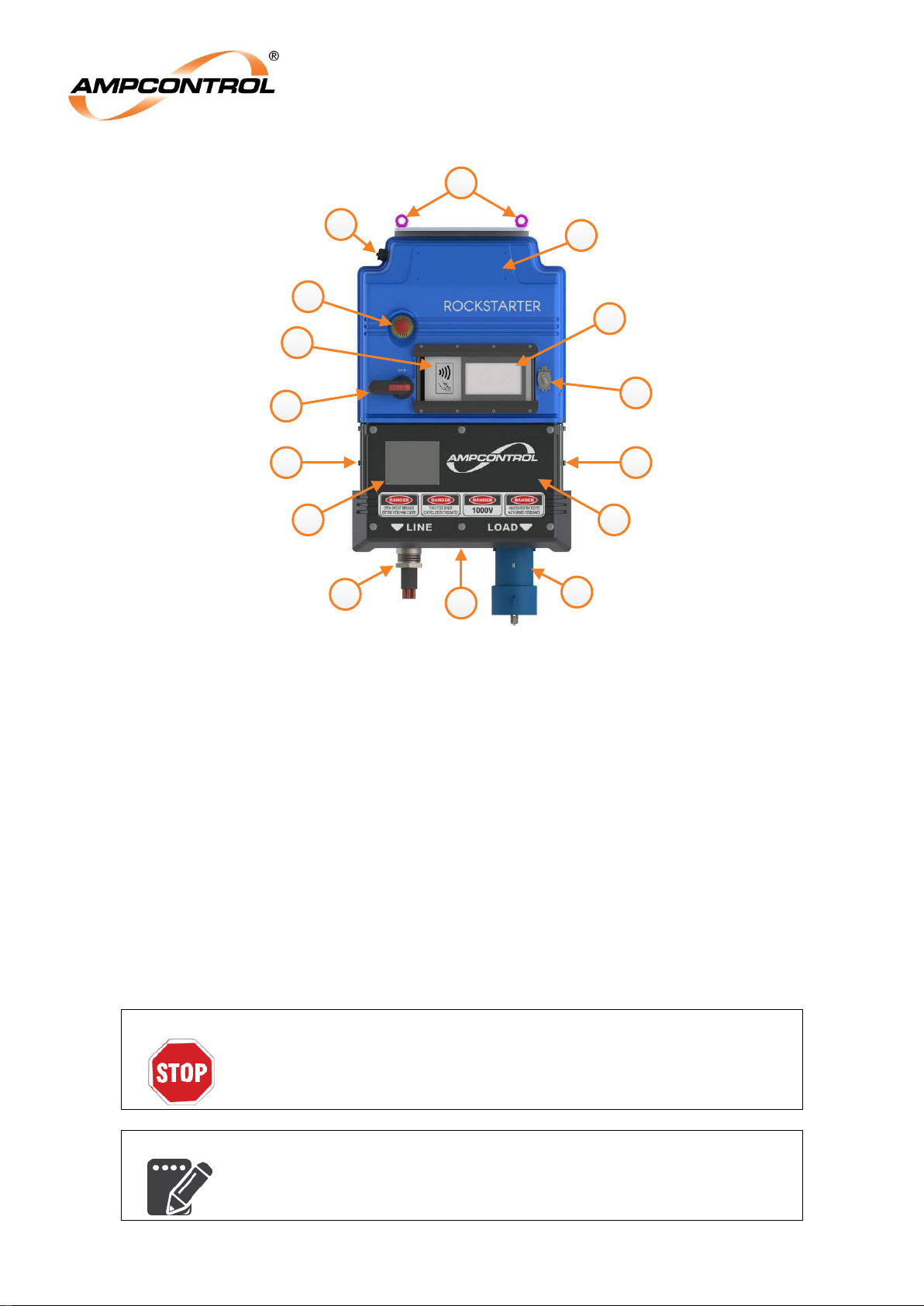
Figure 2: Rockstarter Overview – Single Rockstarter
1.
Incoming feed (accepts gland or optional receptacle)
2.
Chassis earthing stud
3.
Outgoing feed (accepts gland or optional receptacle)
4.
Terminal compartment cover
5.
Main marking label
6.
Through feed
7.
Isolator
8.
E-stop
9.
Ethernet port and auxiliary I/O connector
10.
Lifting adaptor (optional)
11.
Asset number label (optional)
12.
7” LCD touchscreen
13.
RFID tag reader
14.
Lock input
WARNING!
In an emergency, the Emergency Stop button located on the front of the
Rockstarter will stop the outlet.
NOTE
The asset number label is limited to either a single line of 10 characters
with 40mm high text or two lines, each of 10 characters, with 32mm
high text.
Page 17
Ampcontrol Pty Ltd – ABN 28 000 915 542
ROCKSTARTER USER MANUAL
MAG-222 Version 2 – MARCH/19
Uncontrolled Copy - Refer to Ampcontrol Website for Latest Version
Page 17 of 127
APPROVED FOR EXTERNAL DISTRIBUTION
– PROPERTY OF AMPCONTROL PTY LTD
– NOT TO BE REPRODUCED IN PART
Configuration Examples
6
7 8 8
4
5
3
2
1
3
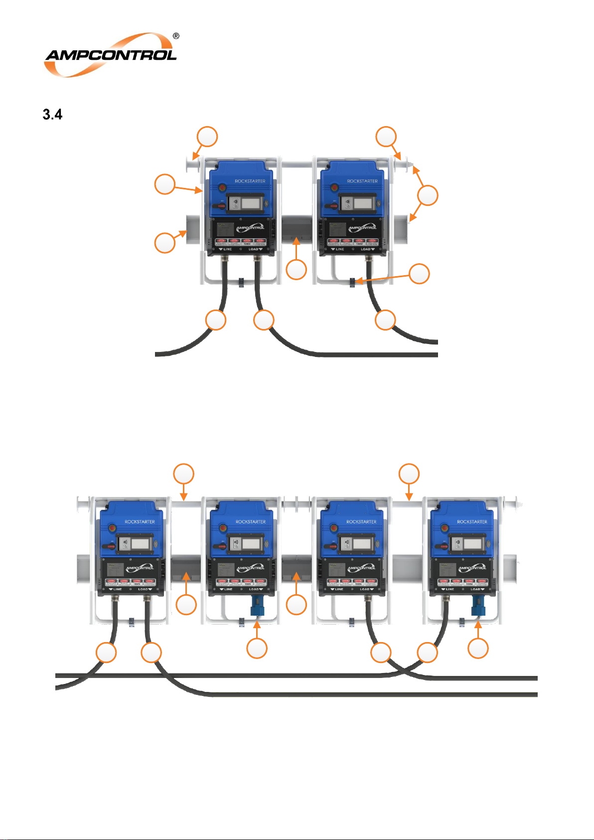
Figure 3: Rockstarter Overview – Two Rockstarters with one incoming feed
1.
Wall mount (optional)
5.
RKS mounting frame to wall mount clamp
2.
RKS mounting frame (optional)
6.
Through feed connection (optional)
3.
Wall mount lifting points
7.
Incoming feed (glanded shown)
4.
Wall mount alignment pins
8.
Outgoing feeds (glanded shown)
1 1
3 3
44
2 2
5 5
Figure 4: Rockstarter Overview – Four Rockstarters with two incoming feeds
1.
Incoming feeds (glanded shown)
4.
Through feed connection (optional)
2.
Outgoing feeds (glanded shown)
5.
Wall mount (optional)
3.
Outgoing feeds (receptacle shown)
Page 18

Ampcontrol Pty Ltd – ABN 28 000 915 542
ROCKSTARTER USER MANUAL
MAG-222 Version 2 – MARCH/19
Uncontrolled Copy - Refer to Ampcontrol Website for Latest Version
Page 18 of 127
APPROVED FOR EXTERNAL DISTRIBUTION
– PROPERTY OF AMPCONTROL PTY LTD
– NOT TO BE REPRODUCED IN PART
Arc Fault Mitigation
The Rockstarter implements high level engineering controls to eliminate the possibility or arcs and faults
being generated. This development of the Rockstarters design provides compliance with the
requirements of AS/NZS3000:2018 and AS/NZS4871.1:2012 in regard to arc fault protection. Are Fault
Mitigation should not be confused with Arc Fault Containment, containment is a lower level of control
against are faults.
Arc Fault Mitigation is achieved through a number of measures. Most notably this includes:
Electrical grade nylon carriers, cable & buswork retention and insulation. All purposed to increase
phase to phase insulation integrity.
Specific design measures to increase phase to phase and phase to earth internal creepage and
clearance distances.
A high ingress protection rating (IP65).
Dedicated internal termination covers to IP2X.
Figure 5: Example of Rockstarter Label
Page 19
Ampcontrol Pty Ltd – ABN 28 000 915 542
ROCKSTARTER USER MANUAL
MAG-222 Version 2 – MARCH/19
Uncontrolled Copy - Refer to Ampcontrol Website for Latest Version
Page 19 of 127
APPROVED FOR EXTERNAL DISTRIBUTION
– PROPERTY OF AMPCONTROL PTY LTD
– NOT TO BE REPRODUCED IN PART
4 INSTALLATION
General Warnings
These instructions have been designed to assist users of the Rockstarter with installation.
Before the Rockstarter can be installed, there are a number of things that need to be considered and
understood to prevent incorrect or unsafe operation of the Rockstarter or the system into which it is
installed. Along with relevant competence, and an understanding of the target application, the following
points should be considered:
Ensure that the information provided in this user manual is fully understood.
It is extremely important that the limitations and functionality of the Rockstarter are understood to prevent
incorrect installation and use from creating a potentially dangerous risk. If in doubt as to the nature of the
limitations or their implication, consult a competent authority such as a supervisor or Ampcontrol
technical representative.
Ensure that the application into which the Rockstarter is being installed has been
properly defined, designed and approved.
Any system intended to mitigate the risk of injury needs to be properly designed and implemented. Such
a system must be the result of structured risk analysis with the outcomes used to define the system
requirements. These requirements, in turn, will guide the choice of instrumentation, logic solvers and
actuators needed to implement the system. Understanding the needs of the system will ensure proper
selection of equipment.
Ensure that the Rockstarter will properly perform the required functions within the
system design.
It is important to understand how the Rockstarter is intended to interact with other equipment within a
system. For safe and reliable use, it is crucial that neither the Rockstarter’s logical operation nor its
signalling be compromised by incompatibilities with connected equipment.
Modifications of any form to the Rockstarter are prohibited.
The Rockstarter as supplied has been designed and manufactured to comply with the requirements of
protection standards. If modifications of any form are made to the Rockstarter, the equipment may no
longer be fit for use. If any modifications or damage to the Rockstarter is evident, do not use the
equipment and contact Ampcontrol for advice.
Mandatory Installation Practices
The following information must be adhered to when installing the Rockstarter. Failure to adhere to this
information may give rise to unsafe operation.
Using the Rockstarter in a manner that exceeds its electrical, functional or physical specifications, or in a
way that is contrary to its operating restrictions, may create risks to personnel and/or equipment resulting
in injury or death.
The Rockstarter must be powered within the specified fault level, voltage and current range.
The installation of the Rockstarter must be carried out by suitably trained and qualified personnel.
Identification labels fixed to the Rockstarter must not be damaged, removed or covered.
The installation shall be in accordance with the relevant installation Standards/Codes of Practice.
Rockstarter must not be modified. The unit is built to, and complies with the relevant standards
and modifications to its design and construction will render the unit non-compliant.
Complete and accurate records of the installation(s) must be maintained.
Page 20
Ampcontrol Pty Ltd – ABN 28 000 915 542
ROCKSTARTER USER MANUAL
MAG-222 Version 2 – MARCH/19
Uncontrolled Copy - Refer to Ampcontrol Website for Latest Version
Page 20 of 127
APPROVED FOR EXTERNAL DISTRIBUTION
– PROPERTY OF AMPCONTROL PTY LTD
– NOT TO BE REPRODUCED IN PART
Mechanical Installation Information
Rockstarter Dimensions
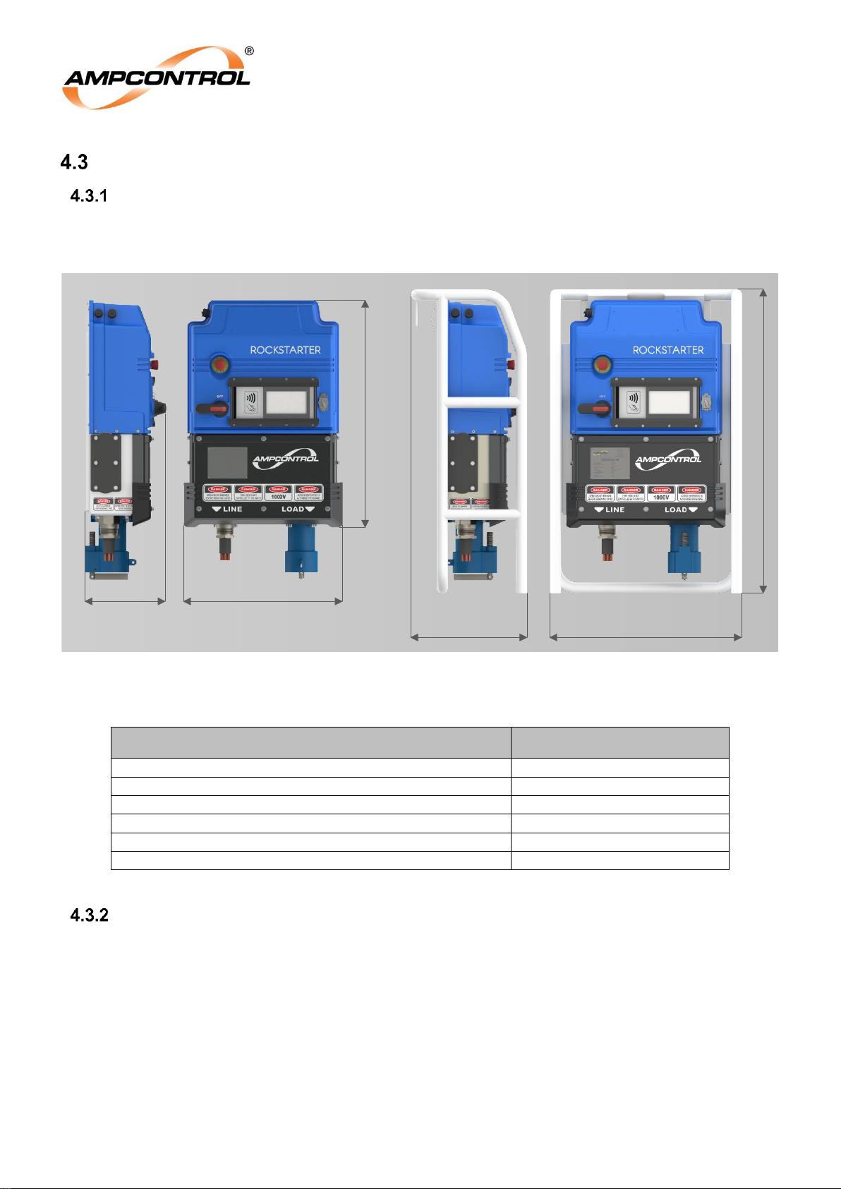
All dimensions shown are excluding cable glands and receptacles. Ensure there is sufficient space
around the unit for mounting hardware, access and cable routing. Consideration must be given to cable
tolerances.
727440
1161
603305
868
Figure 6: Rockstarter Dimensions (mm)
Table 1: Rockstarter Dimensions
Configuration
Dimensions (W x H x D)
Single Rockstarter (no frame)
603 x 868 x 305 mm
Single Rockstarter mounted with lifting adaptor
603 x 930 x 326 mm
Single Rockstarter in mounting frame
727 x 1161 x 440 mm
Single Rockstarter in mounting frame with lifting adapter
727 x 1182 x 440 mm
1 or 2 Rockstarters mounted to wall mount
2055 x 1194 x 442 mm
3 or 4 Rockstarters mounted to wall mount
4055 x 1194 x 442 mm
Mounting Arrangement
There are three optional mounting solutions available for the Rockstarter; the Lifting Adaptor, Mounting
Frame and Mounting Frame with Wall Mount. These are detailed in the following subsections.
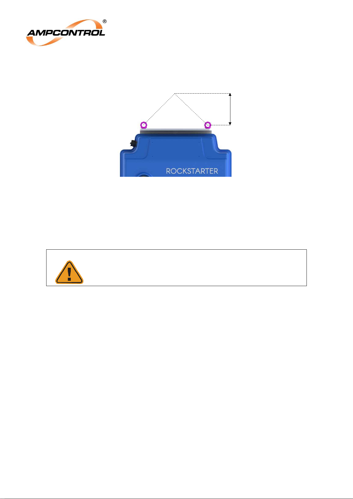
4.3.2.1 Lifting Adaptor
The lifting adaptor consists of a bracket with two VRS-M6 lifting lugs which is secured at the top of the
Rockstarter. The lifting adaptor is secured to the back of the Rockstarter using 4 M8x25mm bolts.
Provisions have also been made for securing the adaptor to the bottom of the Rockstarter. It is
recommended that the lifting adaptor is used for transporting the Rockstarter.
The lifting adaptor is rated for securing the Rockstarter with a sling or chain with an internal angle (α) of
no more than 90°, refer to Figure 7. An internal sling angle of 60 or 90° will result in a sling height
Page 21
Ampcontrol Pty Ltd – ABN 28 000 915 542
ROCKSTARTER USER MANUAL
MAG-222 Version 2 – MARCH/19
Uncontrolled Copy - Refer to Ampcontrol Website for Latest Version
Page 21 of 127
APPROVED FOR EXTERNAL DISTRIBUTION
– PROPERTY OF AMPCONTROL PTY LTD
– NOT TO BE REPRODUCED IN PART
approximately 290mm or 170mm respectively. This additional height, along with any additional mounting
hardware, must be taken into account when selecting a suitable mounting location.
α
Height
Figure 7: Rockstarter Lifting Adaptor
4.3.2.2 Mounting Frame
The mounting frame (refer to Figure 3) provides additional protection, allows for easier handling, and
provides a means to attach the Rockstarter to the wall mount. The frame is secured to the rear of the
Rockstarter using 9 M8x16mm bolts. The mounting frame may be secured to the Rockstarter without
removing the lifting adaptor/s.
CAUTION!
It is recommended that additional mechanical protection be
implemented where there is an elevated risk of damage to the
Rockstarter.
4.3.2.3 Wall Mount
The wall mount kit enables multiple Rockstarters to be mounted together and ensures the correct
spacing for the optional through feed kit; enabling multiple Rockstarters to be connected together with a
single Incoming feed. The maximum number of Rockstarters which may be connected using the through
supply kit is limited by the system protection system and buss ratings. These must be taken into account
when using the through supply kit.
Each wall mount kit supports two Rockstarters, refer to Figure 3. Wall mounts may be connected
together for applications requiring additional Rockstarters, refer to Figure 4. Wall mounts are bolted
together and are keyed to ensure correct alignment.
The process for securing the Rockstarter to the wall mount is as follows:
1. If multiple wall mounts are required, connect the wall mounts together using the supplied
hardware.
2. Mount to wall mounts in the desired location in your operation.
3. Fit Mounting frames to Rockstarter if not already fitted. This is required for alignment and
securing to the wall mount.
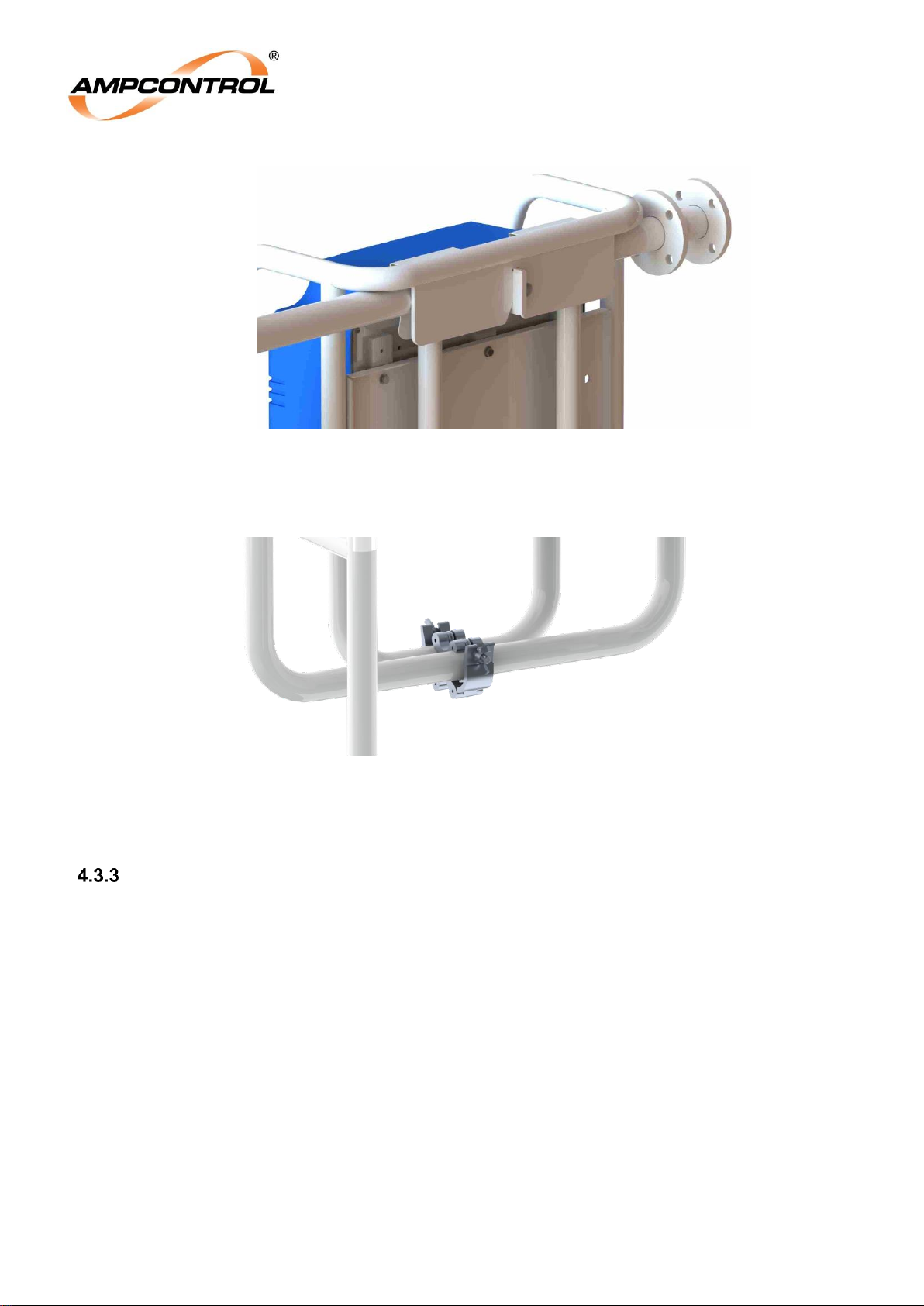
4. Lift the Rockstarter over the wall mount, aligning the slot at the back of the mounting frame with
the tab on the wall mount, refer to Figure 8. The mounting frame and wall mount are keyed and
will self-align provided the Rockstarter is placed near the final position. This ensures correct
spacing for the optional through supply kit.
Page 22
Ampcontrol Pty Ltd – ABN 28 000 915 542
ROCKSTARTER USER MANUAL
MAG-222 Version 2 – MARCH/19
Uncontrolled Copy - Refer to Ampcontrol Website for Latest Version
Page 22 of 127
APPROVED FOR EXTERNAL DISTRIBUTION
– PROPERTY OF AMPCONTROL PTY LTD
– NOT TO BE REPRODUCED IN PART
Figure 8: Rockstarter Wall Bracket Mount
5. Once the Rockstarter is fitted to the wall mount, the unit must be secured using the supplied
clamps, refer to Figure 9.
Figure 9: Mounting Bracket Clamps
6. Install the necessary through feed terminations. For details on the through feed electrical
connections, refer to Section 4.3.5.
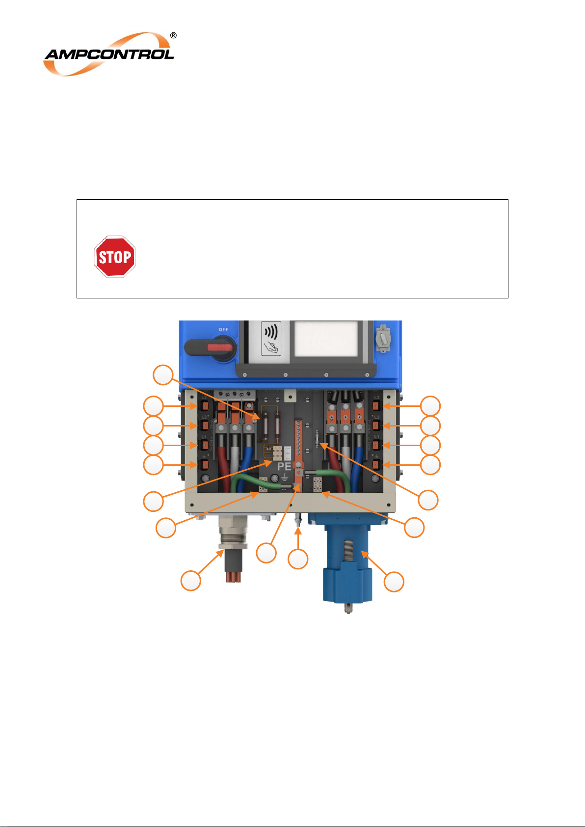
Terminal Compartment Cover
The terminal compartment cover provides access to the incoming, outgoing, through feed and Pilot
termination points. The user replaceable fuses and control supply termination block is also located
behind this cover. The terminal compartment cover can be seen in Figure 10. The terminal compartment
cover is secured with 6 M8x60mm bolts. The cover must not be removed unless the Rockstarter’s circuit
breaker is isolated.
Three secondary terminal covers provide additional protection to the incoming and through feed cable
terminations. These secondary terminal covers must not be removed unless the Rockstarter has been
isolated upstream. The covers must be replaced before the upstream isolation is removed to ensure the
safety of the next operator entering the compartment. Each through feed secondary cover is secured
with two slot head M5x20mm screws while the secondary cover on the incoming feed is secured with 2
M5x10mm Phillips-head screws.
The phase connections for the incoming, outgoing and through feed connections are labelled/engraved
next to the termination points. Torque specifications for these connections are also labelled within the
terminal compartment. The recommended torque for these terminations is 20Nm.
Page 23
Ampcontrol Pty Ltd – ABN 28 000 915 542
ROCKSTARTER USER MANUAL
MAG-222 Version 2 – MARCH/19
Uncontrolled Copy - Refer to Ampcontrol Website for Latest Version
Page 23 of 127
APPROVED FOR EXTERNAL DISTRIBUTION
– PROPERTY OF AMPCONTROL PTY LTD
– NOT TO BE REPRODUCED IN PART
For more information, refer to the following sections:
Incoming and outgoing terminations – refer to Section 4.3.4
Through feed terminations – refer to Section 4.3.5
Pilot termination options – refer to Section 4.4.1 and Section 4.4.2
Control supply termination options – refer to Section 4.4.3
WARNING!
The terminal compartment cover must not be removed unless the
Rockstarter’s circuit breaker is isolated.
The secondary terminal covers must not be removed unless the
Rockstarter has been isolated upstream.
The secondary terminal covers must be replaced before upstream
isolation is removed.
3
13
12
10
11
13
12
10
11
4
1
2
5
6
7
9
8
Figure 10: Rockstarter Terminal Compartment Cover Overview
1.
Incoming feed (glanded shown)
8.
Control supply fuses
2.
Outgoing Feed (receptacle shown)
9.
Auxiliary I/O fuse
3.
Chassis earth
10.
Through feed – earth
4.
Earth busbar
11.
Through feed – L1
5.
Incoming pilot termination block
12.
Through feed – L2
6.
Outgoing pilot termination block
13.
Through feed – L3
7.
Control supply termination block
Page 24
Ampcontrol Pty Ltd – ABN 28 000 915 542
ROCKSTARTER USER MANUAL
MAG-222 Version 2 – MARCH/19
Uncontrolled Copy - Refer to Ampcontrol Website for Latest Version
Page 24 of 127
APPROVED FOR EXTERNAL DISTRIBUTION
– PROPERTY OF AMPCONTROL PTY LTD
– NOT TO BE REPRODUCED IN PART
Incoming & Outgoing Cable Terminations
The Rockstarter’s incoming and outgoing connections may be configured to suit either a glanded cable
entry or a restrained receptacle. The incoming and outgoing feeds natively support a 300A receptacle
footprint while the blanking plate may be drilled to accommodate glanded cables up to 120mm2. The
incoming and outgoing gland/blanking plates, 300A restrained receptacles and adapter plates are
secured using 4x M12x45mm bolts.
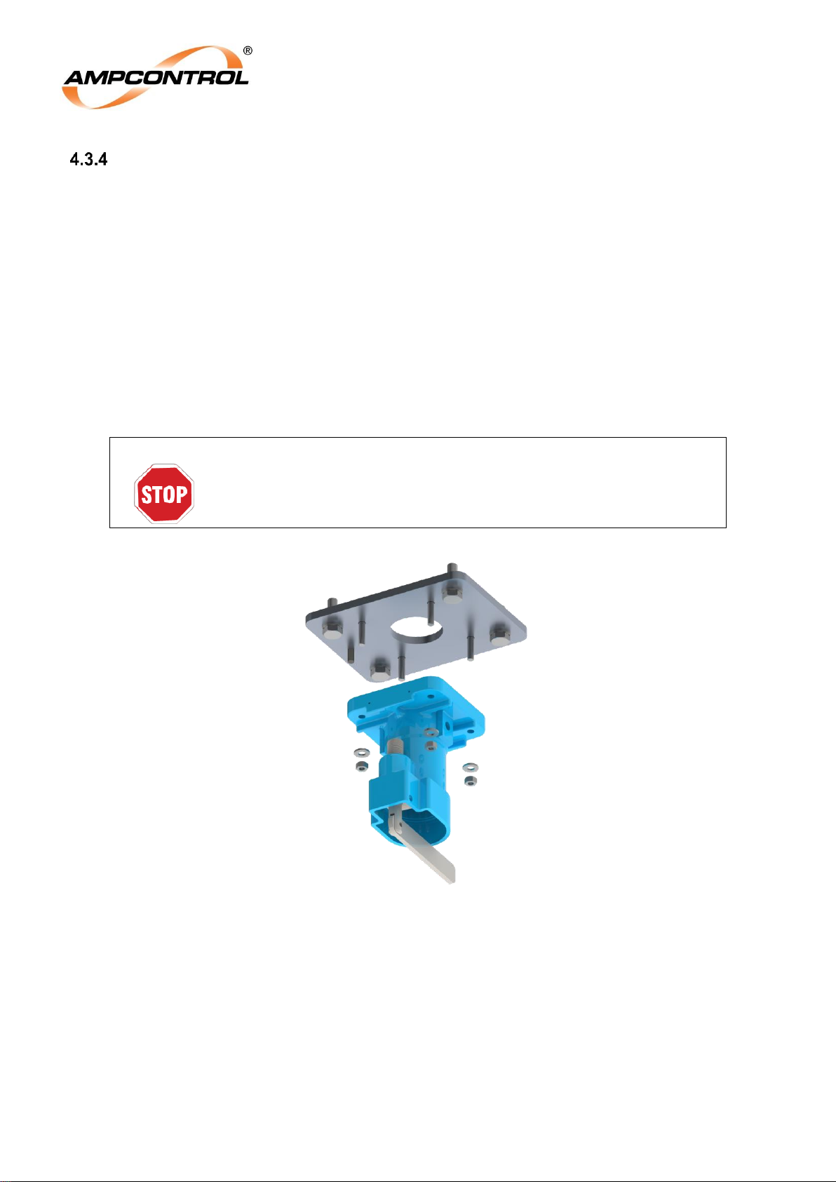
Support for 60A and 150A receptacles is provided via two optional adaptor plates, refer to Figure 11. The
60A adaptor plate contains 4 countersunk M8x40mm hex head bolts spaced appropriately for the two
receptacles. The 150A adaptor plate contains 4 countersunk M12x45mm hex head bolts spaced
appropriately for the two receptacles.
All gland/blanking plates, receptacles and adaptor plates are bolted through the Rockstarter enclosure
and secured to a threaded backing plate. All unused entries must be sealed using Ampcontrol supplied
gland plates to maintain the IP rating of the starter.
WARNING!
All unused entries must be sealed using Ampcontrol supplied gland
plates.
Figure 11: Rockstarter Adaptor Plate (60A pictured)
4.3.4.1 Termination Extension Housing Kit
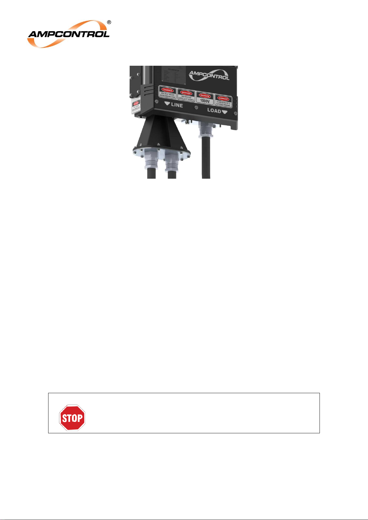
The optional termination extension kit provides a 230mm extension for incoming glanded cables. When
combined with the optional dual incomer termination, the termination extension kit allows the incoming
feed of the Rockstarter to branch off to supply another load.
The incoming termination extension kit is secured to the incoming feed of the Rockstarter using 4
M12x45mm bolts while the gland plate is secured to the base of the extension housing with 8 M8x35mm
bolts. The gland plate is supplied as a solid piece and must be drilled to accommodate glanded cables.
Page 25
Ampcontrol Pty Ltd – ABN 28 000 915 542
ROCKSTARTER USER MANUAL
MAG-222 Version 2 – MARCH/19
Uncontrolled Copy - Refer to Ampcontrol Website for Latest Version
Page 25 of 127
APPROVED FOR EXTERNAL DISTRIBUTION
– PROPERTY OF AMPCONTROL PTY LTD
– NOT TO BE REPRODUCED IN PART
Figure 12: Dual Gland J-Box
4.3.4.2 Dual Incomer Termination
The dual incomer termination must be used in conjunction with the termination extension housing kit and
allows the Rockstarter’s incoming feed to branch off to supply another load.
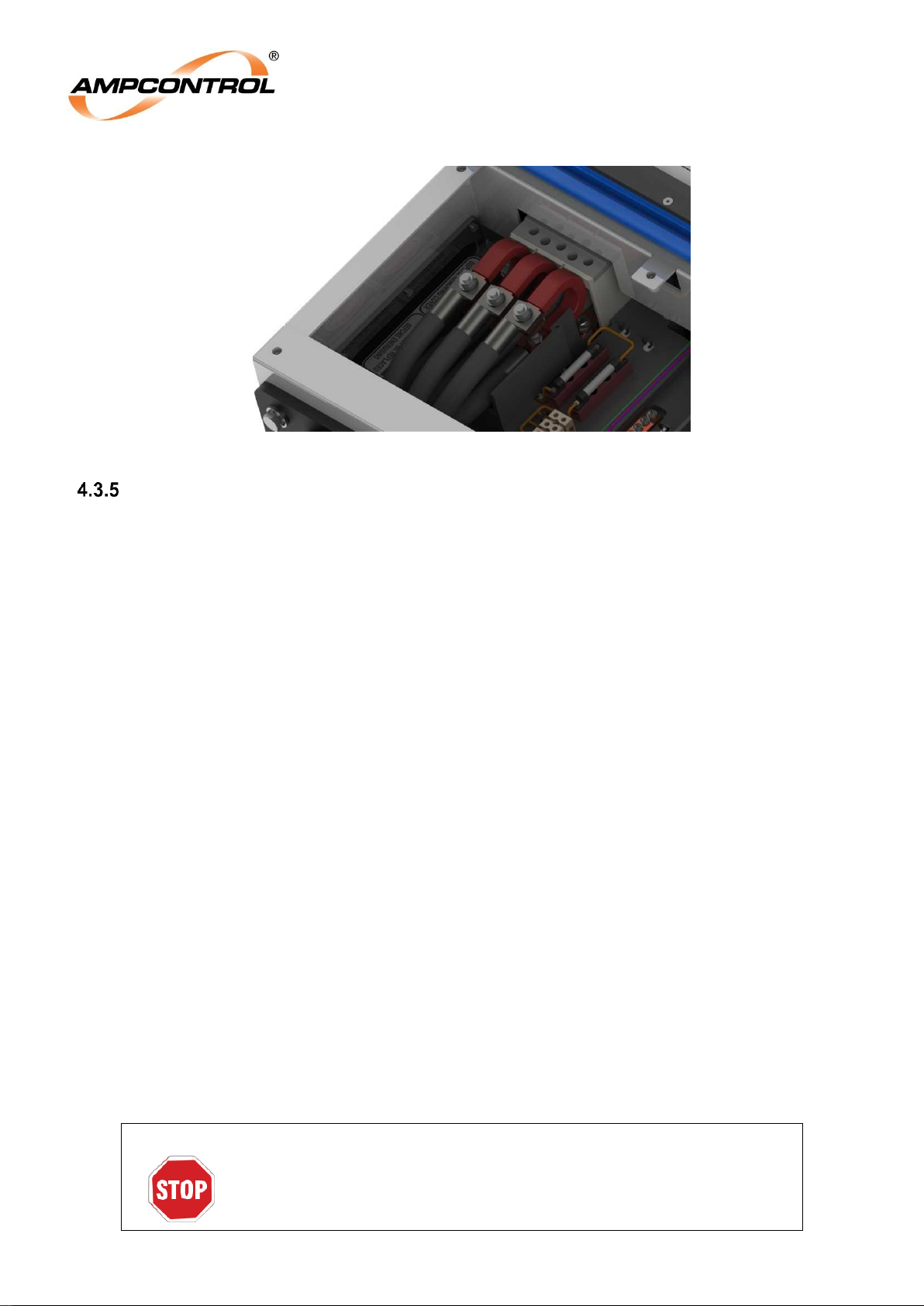
The process for installing the Rockstarter’s dual incomer termination is as follows:
1. Remove the terminal compartment cover and secondary cover to the incoming feed. Ensure
correct isolation procedures are followed.
2. The flexible buses allow the second termination point to move out of the way while securing the
incoming feed/first termination point to the original incomer termination point of the Rockstarter as
per normal.
3. Thread the supplied insulation sleeve over the second incoming cable and away from termination
point. Leave loose.
4. Secure the second incoming cables to the second termination point on the flexible busbar. The
recommended torque for the dual incomer terminations is 20Nm. Alternatively, this can be done
before securing the first termination point, order will depend on installer.
5. Re-install the incomer terminal cover under the secondary termination points.
6. Finally slide the loose insulation sleeve back over the second termination point and around the
flexible busbar until it contacts the circuit breaker (approximately 60-80mm past the termination
fastener). Secure in place using a cable tie on both sides.
WARNING!
The insulation sleeve must maintain a minimum 50mm overlap over the
insulation of the flexible busbar and second incoming cable to maintain
safety ip2x protection.
Page 26
Ampcontrol Pty Ltd – ABN 28 000 915 542
ROCKSTARTER USER MANUAL
MAG-222 Version 2 – MARCH/19
Uncontrolled Copy - Refer to Ampcontrol Website for Latest Version
Page 26 of 127
APPROVED FOR EXTERNAL DISTRIBUTION
– PROPERTY OF AMPCONTROL PTY LTD
– NOT TO BE REPRODUCED IN PART
Figure 13: Dual Incomer Termination
Through Connection
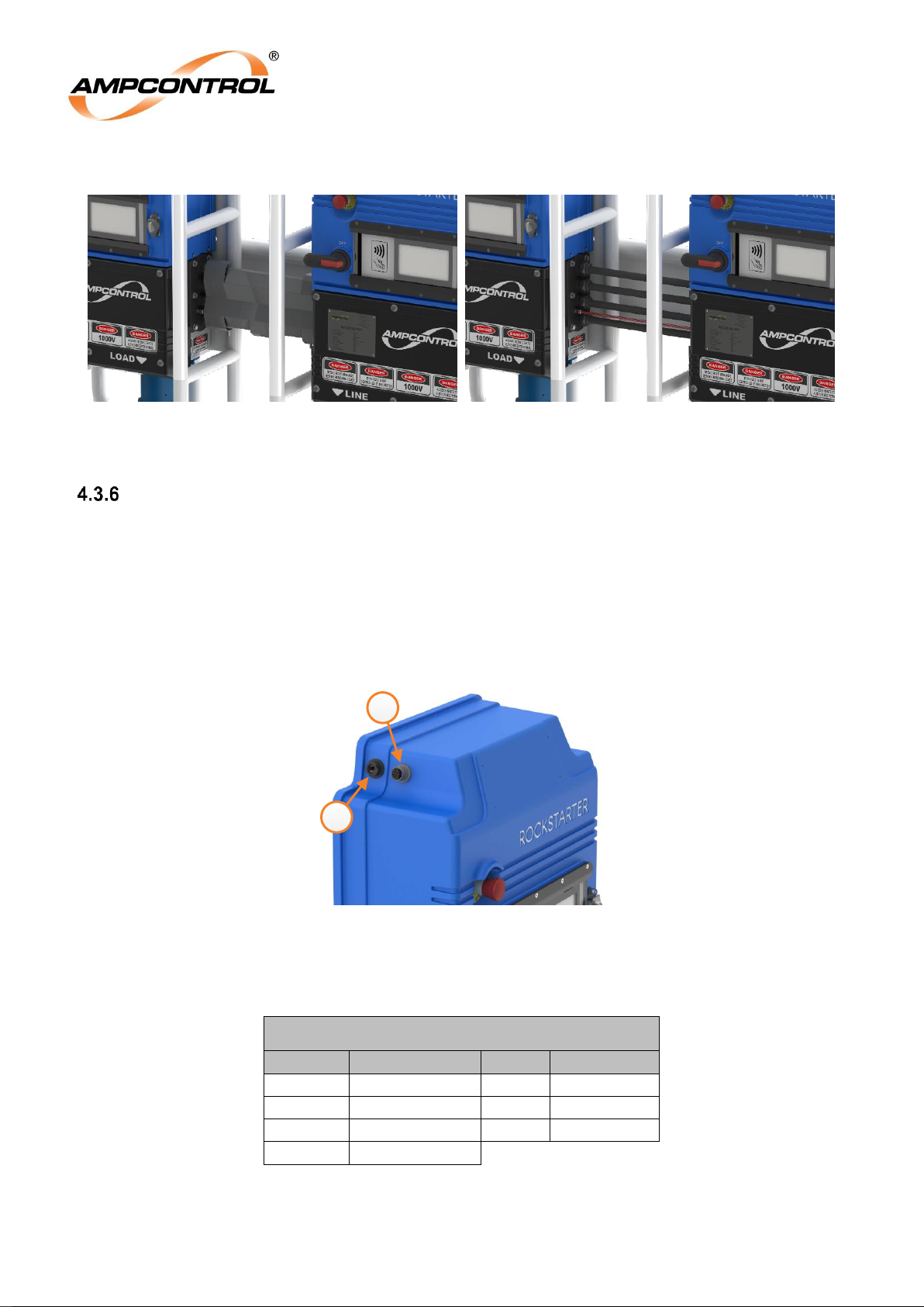
The through supply kit enables multiple Rockstarters to be connected together with a single incoming
supply. The through supply kit must only be used with all connected Rockstarters mounted to the wall
mount assembly. Ensure through connections are only performed with Ampcontrol supplied accessories.
To fit the through supply kit, ensure correct isolation procedures are followed to isolate upstream supply:
1. Ensure all Rockstarters are mounted to the same wall mount assembly as detailed in Section
4.3.2.
2. Remove the terminal compartment cover and secondary cover to the appropriate through feed
connection/s on both Rockstarters to be joined.
3. Remove the blanking plates from the appropriate through feed connections.
4. Through feed connections are supplied assembled. Position the assembly between the two
Rockstarters and position all cable lugs in the appropriate position. Ensure the O-ring is
undamaged and in position.
5. Firmly secure all hardware.
a. Secure the through feed cables on both Rockstarters. The pre-terminated through feed
cables are secured to the appropriate phase bus termination points via M8 bolts with a
recommended torque of 20Nm.
b. Secure gland plates to the Rockstarter via 6 M8x25mm bolts.
c. Tighten the nylon gland in the gland plates to secure the cables and obtain the IP rating.
6. If required, remove the appropriate pilot blanking plugs are replace with glands. Feed the pilot
wire through the glands and connect as detailed in Section 4.4.1.2.
7. Install through feed cable cover. The cover clips over the cables.
8. Secure all internal IP2X terminal covers
9. Install terminal compartment cover.
When the through supply functionality is not required, all cable entries and exits must be sealed using
Ampcontrol supplied blanking plates. Ensure unused pilot entries are sealed using nylon blanking plugs.
WARNING!
The through supply kit must only be used with all connected
Rockstarters mounted to the wall mount assembly.
Ensure through connections are only performed with Ampcontrol
supplied accessories.
Page 27
Ampcontrol Pty Ltd – ABN 28 000 915 542
ROCKSTARTER USER MANUAL
MAG-222 Version 2 – MARCH/19
Uncontrolled Copy - Refer to Ampcontrol Website for Latest Version
Page 27 of 127
APPROVED FOR EXTERNAL DISTRIBUTION
– PROPERTY OF AMPCONTROL PTY LTD
– NOT TO BE REPRODUCED IN PART
Figure 14: Through Feed – with (left) & without (right) cover
Auxiliary I/O & Ethernet Connectors
The Rockstarter is equipped with an Ethernet and auxiliary I/O connector at the top of the unit, refer to
Figure 15 item 1 and 2. Ethernet connectivity is provided by way of an RJ45. The auxiliary I/O connector
utilises a Bulgin PXP6012/16S/CR connector, refer to Table 2 for the auxiliary I/O connector pinout. An
optional I/O J-Box and connecting cables are available for easy connection to the Rockstarter’s auxiliary
I/O connector. The connecting cable is available in 1, 2 and 5 metre lengths. For applications which only
require fan sequencing, an optional, pre-terminated fan sequencing cable is available. Refer to Section
7.2.3 for an overview of fan sequenced starts.
2
1
Figure 15: Ethernet & Terminal I/O Connector
Table 2: Terminal I/O Connector Pinout
Auxiliary I/O Connector
Pin
Label (I/O)
Pin
Label (I/O)
1,2,3,4,5
Factory Use
11,12
Reset (I)
6,7
Run (O)
13,14
Stop (I)
8
Spare
15,16
Start (I)
9,10
Delay Start (I)
Page 28
Ampcontrol Pty Ltd – ABN 28 000 915 542
ROCKSTARTER USER MANUAL
MAG-222 Version 2 – MARCH/19
Uncontrolled Copy - Refer to Ampcontrol Website for Latest Version
Page 28 of 127
APPROVED FOR EXTERNAL DISTRIBUTION
– PROPERTY OF AMPCONTROL PTY LTD
– NOT TO BE REPRODUCED IN PART
Load Connection Module (LCM)
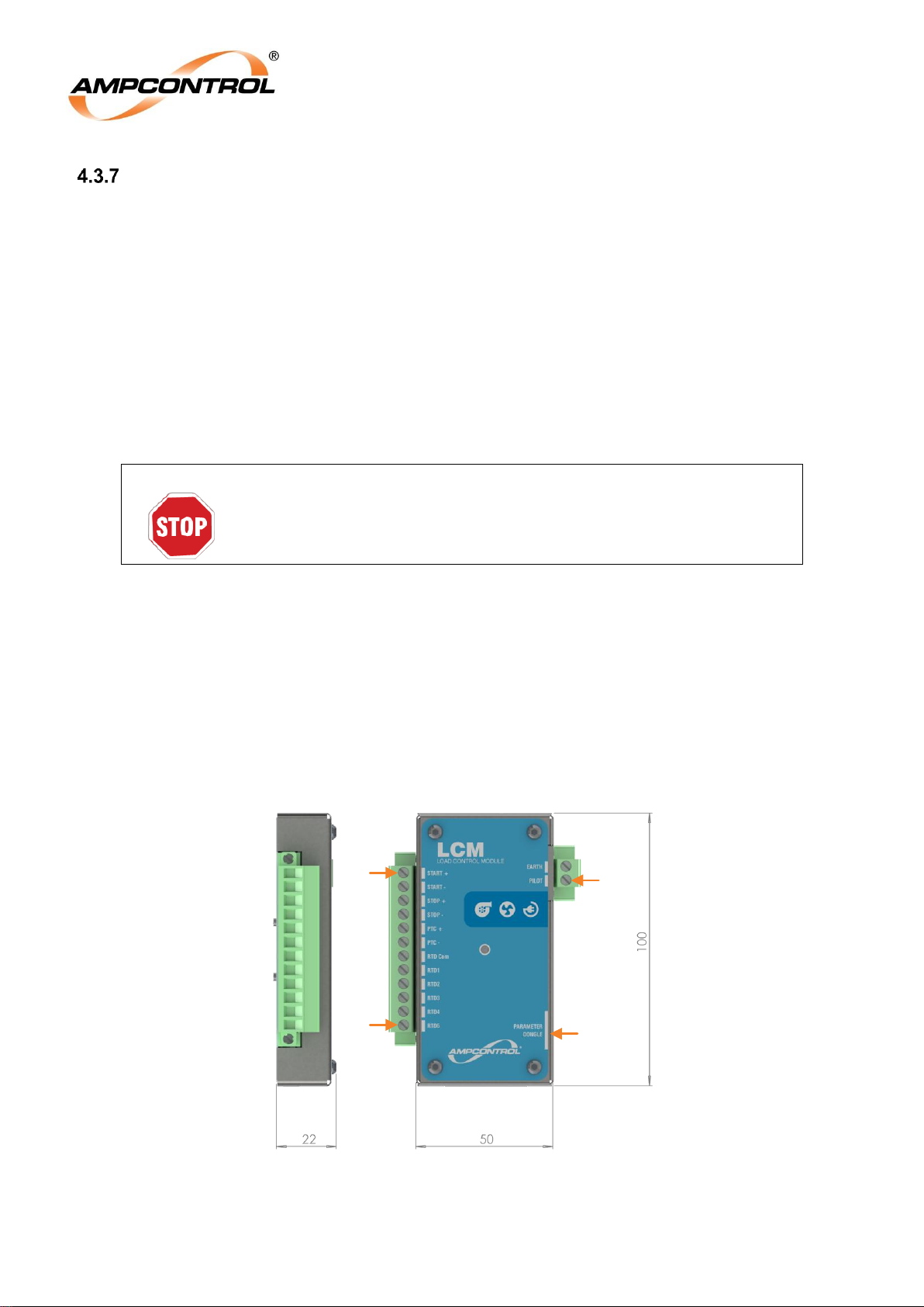
The LCM is a microprocessor based module that can be utilised to replace the diode at the end of the
trailing cable pilot conductor. It is powered by and communicates via the pilot line. Its non-volatile
memory stores the Rockstarters configuration and protection settings, allowing load identification and
protections settings to be utilised whenever the load is used.
All LCM terminals are fully shrouded, with the pilot and earth terminals being segregated from the other
control and monitoring terminals.
The LCM provides remote start and stop input facilities. The circuitry involved in these functions is selfdiagnostic and will cause the outlet to turn off if the circuits are earthed or interconnected. This reduces
the chance of the outlet operating when not required to do so due to wiring faults. It should be noted that
these functions are operational only, and that any emergency stops should be wired directly into the pilot
circuit.
WARNING!
Any emergency stops should be wired directly into the pilot circuit.
PTC terminals are provided for a semiconductor ‘switching’ thermistor. These terminals are protected in
a similar manner to the stop and start circuits.
Five RTD inputs are provided for PT100 RTDs. The Rockstarter can be programmed to trip on RTD
over-temperature.
A parameter dongle allows an LCM to be replaced without needing to re-program the parameters. When
installed, this dongle should be firmly secured to the machine/equipment. The relevant settings changes
made on the connected Rockstarter are automatically pushed to the LCM parameter dongle.
1
12
14
Parameter
Dongle
Figure 16: Load Connection Module (LCM) (mm)
Page 29
Ampcontrol Pty Ltd – ABN 28 000 915 542
ROCKSTARTER USER MANUAL
MAG-222 Version 2 – MARCH/19
Uncontrolled Copy - Refer to Ampcontrol Website for Latest Version
Page 29 of 127
APPROVED FOR EXTERNAL DISTRIBUTION
– PROPERTY OF AMPCONTROL PTY LTD
– NOT TO BE REPRODUCED IN PART
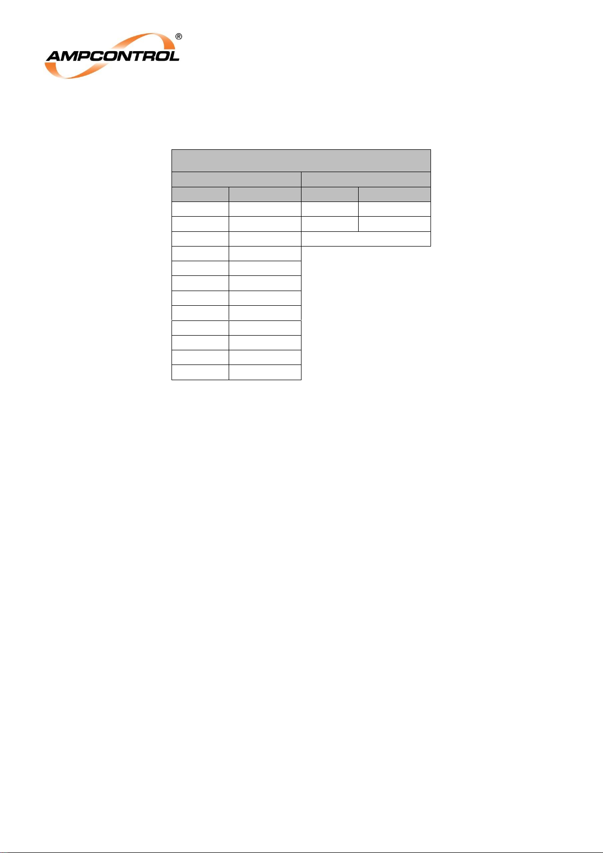
Table 3: LCM Pinout
LCM
Left Side
Right Side
Terminal
Description
Terminal
Description
1
Start +
13
Earth
2
Start -
14
Pilot
3
Stop +
Parameter Dongle
4
Stop - 5 PTC + 6 PTC -
7
RTD Com
8
RTD1 9 RTD2
10
RTD3
11
RTD4
12
RTD5
Page 30
Ampcontrol Pty Ltd – ABN 28 000 915 542
ROCKSTARTER USER MANUAL
MAG-222 Version 2 – MARCH/19
Uncontrolled Copy - Refer to Ampcontrol Website for Latest Version
Page 30 of 127
APPROVED FOR EXTERNAL DISTRIBUTION
– PROPERTY OF AMPCONTROL PTY LTD
– NOT TO BE REPRODUCED IN PART
Electrical Installation Information
NER
L1
Rockstarter Enclosure
User
Replaceable
fuses
Incoming
Feed
Protection
Electronics
User
Interface
TXF
Main Supply
M
Chassis
Earthing
Stud
Outgoing
Feed
Circuit
Breaker
Main
Contactor
MC
CB
Through
Feed
U V W
Earth Earth
Earth
Earth
L2 L3
L1
L2
L3
L1
L2
L3
E-Stop
Optional
Incoming Pilot
Termination
Through
Feed
Motor
Enclosure
OPT 2. Diode Remote Start
100Ω
STOP
PILOT
START
7" LCD
EC
Monitored
shunt trip
supply
CBR
MCR
PILOT
OPT 1. Diode Termination
LCM
RTD’s
Digital
Inputs
x5
OPT 3. LCM Termination
4A slow-blow
HRC
Control
Transformer
Termination
Optional
Outgoing Pilot
Termination
1000V
690V
415V
Ethernet
Auxiliary I/O
Connector
RFIDLock Input
Auxiliary I/O
Fuse
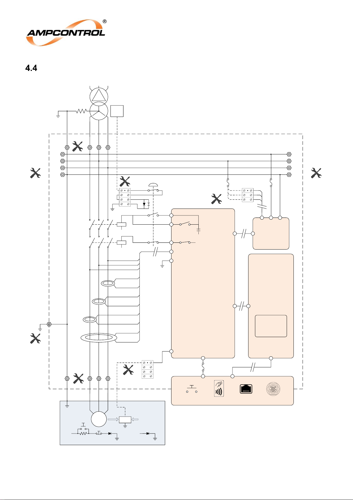
Figure 17: Electrical Connection Diagram
Page 31
Ampcontrol Pty Ltd – ABN 28 000 915 542
ROCKSTARTER USER MANUAL
MAG-222 Version 2 – MARCH/19
Uncontrolled Copy - Refer to Ampcontrol Website for Latest Version
Page 31 of 127
APPROVED FOR EXTERNAL DISTRIBUTION
– PROPERTY OF AMPCONTROL PTY LTD
– NOT TO BE REPRODUCED IN PART
WARNING!
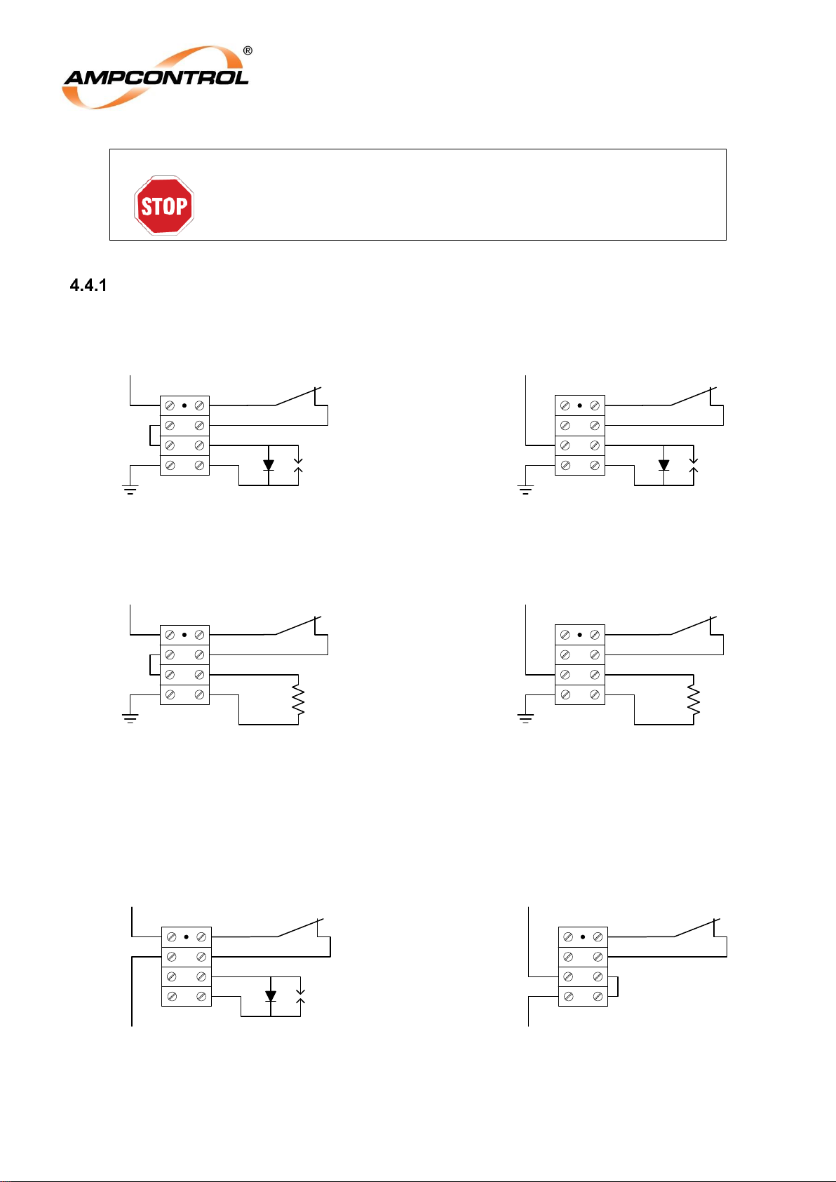
Pilot terminations must be continuous.
Incoming Pilot
4.4.1.1 Incoming Terminations
E-Stop
Pilot in
Diode + E-Stop Termination
Diode termination
Resistor + E-Stop Termination
Resistor Termination
E-Stop
Pilot in
E-Stop
Pilot in
E-Stop
Pilot in
[Default]
Figure 18: Incoming Pilot – Terminations
4.4.1.2 Through Terminations
Pilot Pass Through + E-Stop
Pilot Pass Through
Pilot Out
E-Stop
Pilot in
E-Stop
Pilot in
Pilot Out
Figure 19: Incoming Pilot – Through Terminations
Page 32
Ampcontrol Pty Ltd – ABN 28 000 915 542
ROCKSTARTER USER MANUAL
MAG-222 Version 2 – MARCH/19
Uncontrolled Copy - Refer to Ampcontrol Website for Latest Version
Page 32 of 127
APPROVED FOR EXTERNAL DISTRIBUTION
– PROPERTY OF AMPCONTROL PTY LTD
– NOT TO BE REPRODUCED IN PART
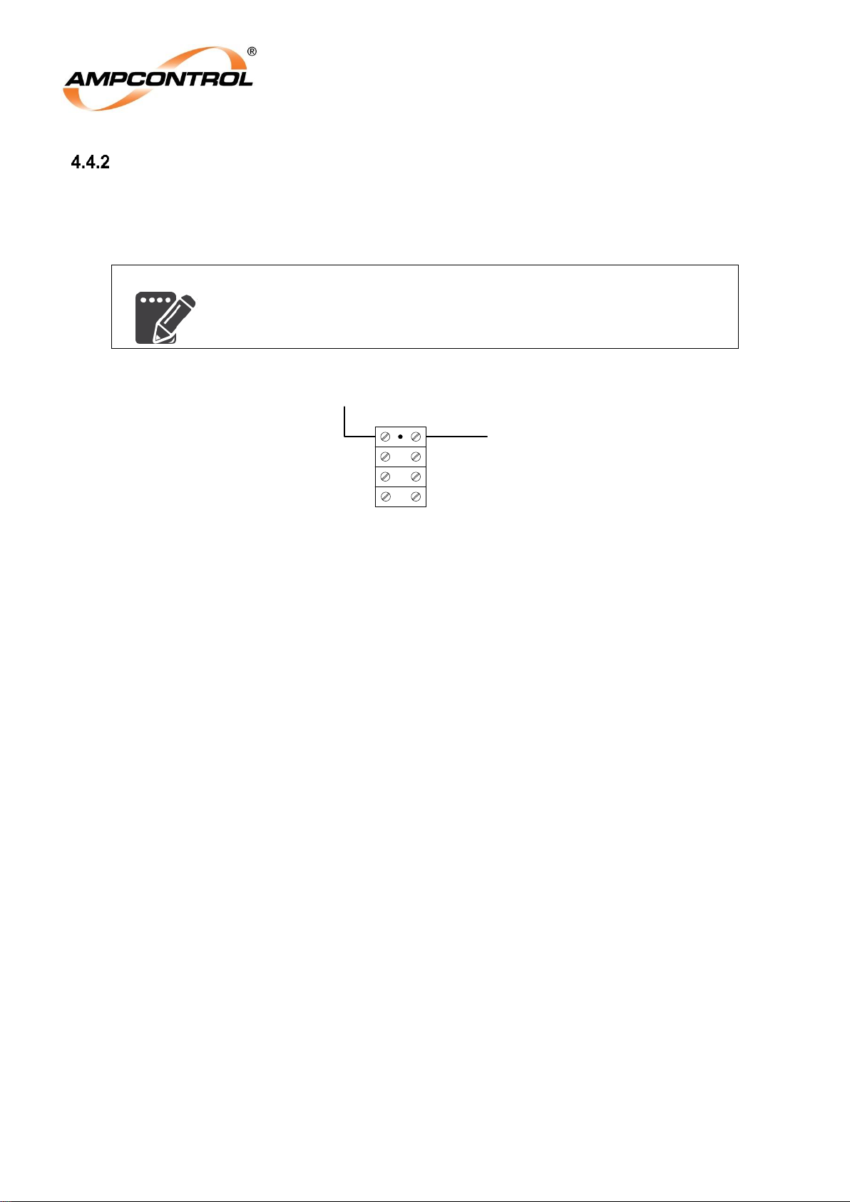
Outgoing Pilot
Earth continuity protection can be disabled in the UI when not required. For applications requiring EC
protection, the outgoing pilot can be connected to the outgoing pilot terminal block (See Figure 10 for
location) in the terminal compartment.
NOTE
Remote starts will not be possible when earth continuity protection is
disabled, regardless of the pilot termination mode.
Outgoing Pilot Connection
Outgoing Pilot
RKS Pilot
Figure 20: Outgoing Pilot – Terminations
4.4.2.1 Diode Termination
If enabled, the Rockstarter’s earth continuity protection monitors the presence of a termination diode that
is installed in the motor enclosure to ensure that there is a continuous earth connection between the
supply enclosure and the motor enclosure via the outlet cable. Ampcontrol recommends our pilot
termination module (PN 115119), alternatively a 1N5404 diode can be utilised.
4.4.2.2 Diode Remote Start Termination
A remote start button can be implemented in the motor enclosure provided that the Rockstarter’s earth
continuity protection is enabled and the remote start function is enabled within the UI.
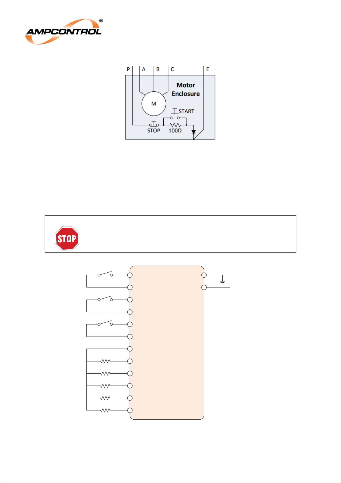
In order to install a remote start push button, wire a 100Ω, 1%, 5W resistor in series with the pilot
conductor, refer to Figure 21. With the resistor installed, wire a push button with a normally open contact
in parallel with this 100Ω resistor so that it will short out the resistor when the button is pressed.
For more information on the operation of the Rockstarter’s Remote Start Function, refer to Section 8.2.2.
4.4.2.3 Diode Remote Stop Termination
A remote stop button can be implemented in the motor enclosure provided that the Rockstarter’s earth
continuity protection is enabled.
In order to install a remote stop push button, wire a normally closed contact in series with the pilot
conductor, refer to Figure 21. When the push button is pressed the pilot will open circuit, initiating an
earth continuity trip, which will open the outlet’s contactor.
For more information on the operation of the Rockstarter's Remote Stop Function, refer to Section 8.2.3.
Page 33
Ampcontrol Pty Ltd – ABN 28 000 915 542
ROCKSTARTER USER MANUAL
MAG-222 Version 2 – MARCH/19
Uncontrolled Copy - Refer to Ampcontrol Website for Latest Version
Page 33 of 127
APPROVED FOR EXTERNAL DISTRIBUTION
– PROPERTY OF AMPCONTROL PTY LTD
– NOT TO BE REPRODUCED IN PART
Figure 21: Remote Stop/Start
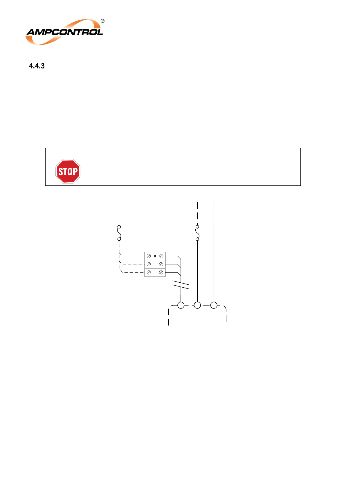
4.4.2.4 Load Connection Module (LCM)
A remote Start / Stop button can be implemented in the motor enclosure provided that the Rockstarter’s
earth continuity protection is enabled. If the remote start, stop, and PTC functions are not required, each
set of terminals must be bridged to prevent incorrect data and control inputs being detected.
WARNING!
Any emergency stops should be wired directly into the pilot circuit.
LCM
RTD 1
Earth
RTD COM
RTD 2
RTD 3
RTD 4
RTD 5
PTC +
PTC -
START +
START -
STOP +
STOP -
Pilot
Incoming
Pilot
Figure 22: Load Connection Module (LCM) – Connection Diagram
Page 34
Ampcontrol Pty Ltd – ABN 28 000 915 542
ROCKSTARTER USER MANUAL
MAG-222 Version 2 – MARCH/19
Uncontrolled Copy - Refer to Ampcontrol Website for Latest Version
Page 34 of 127
APPROVED FOR EXTERNAL DISTRIBUTION
– PROPERTY OF AMPCONTROL PTY LTD
– NOT TO BE REPRODUCED IN PART
Fuses & Control Supply Termination
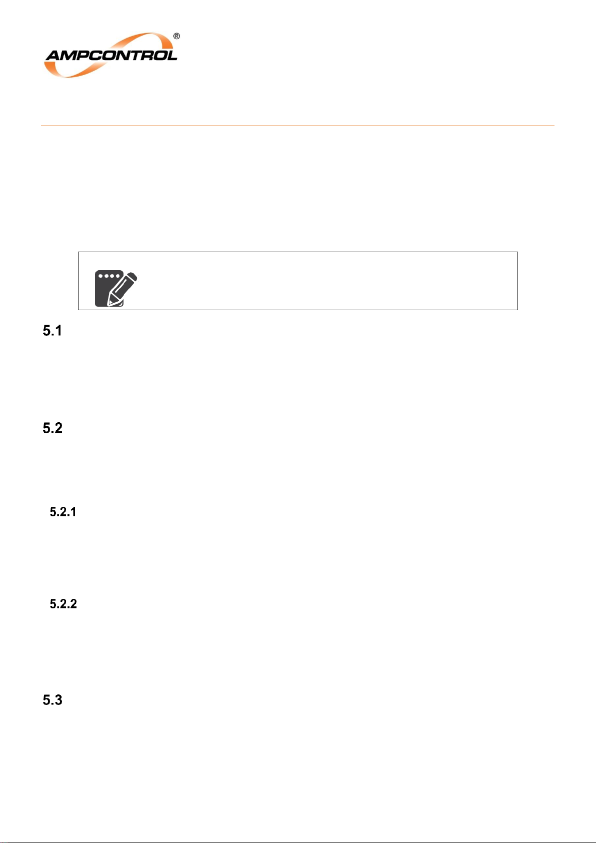
The Rockstarter contains two user-replaceable fuses protecting the control supply transformer. The Bphase (L1) fuse connects to the transformer via a terminal block which allows for configuration of the
transformer’s primary tap, refer to Figure 23. This must be correctly connected for the appropriate line
voltage in conjunction with the appropriate voltage setting within the HMI. The termination block is
labelled within the terminal compartment. The factory default configuration has supply connected to the
1000VAC terminal.
A third auxiliary I/O fuse is also located in the termination compartment. This supply is fed through to the
AUX connector at the top of the Rockstarter and is for Ampcontrol diagnostic use only.
WARNING!
The system voltage must be set in conjunction with the appropriate
control supply termination, ensuring the outlet is correctly configured for
the system line voltage
4A slow-blow
HRC
Control
Transformer
Termination
1000V
690V
415V
TXF
Figure 23: Control Supply Termination
Page 35
Ampcontrol Pty Ltd – ABN 28 000 915 542
ROCKSTARTER USER MANUAL
MAG-222 Version 2 – MARCH/19
Uncontrolled Copy - Refer to Ampcontrol Website for Latest Version
Page 35 of 127
APPROVED FOR EXTERNAL DISTRIBUTION
– PROPERTY OF AMPCONTROL PTY LTD
– NOT TO BE REPRODUCED IN PART
5 COMMISSIONING
Prior to being put into service, the electrical protection system must be correctly commissioned. This
manual does not cover system commissioning; the full scope of commissioning tests should be
determined during the risk assessment or FMEA covering the design of the electrical protection system.
The following tests can provide guidance on checking the correct operation of the Rockstarter during
commissioning. This is not intended to provide an exhaustive commissioning checklist, but should be
considered to be a minimum set of tests.
All tests and trips can be monitored through the Log menu on the Rockstarter HMI. When testing is
undertaken, the logs should be monitored to ensure all events are captured and logged correctly.
NOTE
Running a full OTS test sequence gives coverage of all touch potential
protection items outlined in sections 5.1, 5.2, 5.3 and 5.5.
Earth Leakage
Test the correct operation of earth leakage circuits by injecting a fault current through the Earth Leakage
CT. This can be undertaken via the HMI (refer to Section 6.1). Ensure that the MC successfully trips and
requires an authorised reset. The indication LEDs on the fascia of the Rockstarter should illuminate
yellow to indicate a trip (detailed in Section 6.1.5) and the HMI should display the relevant trip messages.
The correct operation of the earth leakage protection may be verified by running an OTS test.
Earth Continuity
Required if: Earth Continuity Protection is enabled
In order to test that the earth continuity protection is functioning correctly, series and shunt resistance
tests must be performed. These tests will verify that the earth continuity protection is functioning. The
correct operation of the earth continuity protection may be verified by running an OTS test.
Earth Continuity – Series
The EC series resistance trip can be verified by creating an open circuit in the pilot line. This can be
achieved through the HMI (refer to Section 6.1). Ensure that the contactor successfully trips and either
requires a general reset (if EC latching selected) or automatically resets (if non-latching mode is
selected). The indication LEDs on the fascia of the Rockstarter should illuminate yellow to indicate a trip
(detailed in Section 6.1.5) and the HMI should display the relevant trip messages.
Earth Continuity – Shunt
The EC shunt resistance trip can be verified by creating a short circuit between the pilot line and earth.
This can be achieved through the HMI (refer to Section 6.1). Ensure that the contactor successfully trips
and either requires a general reset (if EC latching selected) or automatically resets (if non-latching mode
is selected). The indication LEDs on the fascia of the Rockstarter should illuminate yellow to indicate a
trip (detailed in Section 6.1.5) and the HMI should display the relevant trip messages.
Earth Fault Lockout
The earth fault lockout protection can be tested by connecting a suitably rated test resistor to a single
outgoing power conductor. Attempt to energise the outlet and confirm that the protection module trips on
earth fault lockout and fails to close the MC. This test should be repeated for all phases. The indication
LEDs on the fascia of the Rockstarter should illuminate yellow to indicate a trip (as detailed in Section
6.1.5) and the HMI should display the relevant trip messages. The correct operation of the earth fault
lockout protection can be verified by running a full OTS test sequence.
Page 36
Ampcontrol Pty Ltd – ABN 28 000 915 542
ROCKSTARTER USER MANUAL
MAG-222 Version 2 – MARCH/19
Uncontrolled Copy - Refer to Ampcontrol Website for Latest Version
Page 36 of 127
APPROVED FOR EXTERNAL DISTRIBUTION
– PROPERTY OF AMPCONTROL PTY LTD
– NOT TO BE REPRODUCED IN PART
WARNING!
If the earth fault lockout protection fails, full system voltage and
power may be subsequently applied to the test resistors.
Insulation Test (High Voltage)
The Rockstarter Cable Connection Module (CCM) will present a resistance to earth on each phase when
performing a HV insulation test on the outgoing connections. It is recommended that HV insulation tests
not be carried out on the outgoing terminals of the Rockstarter to prevent damage to the CCM.
When performing HV insulation tests on the incoming and subsequent through feed connections, it is
recommended that the CB’s be opened and the control transformer fuses be removed.
Main Contactor Fail
While the Rockstarter is stopped (MC open), apply a voltage on the load side of the contactor. The
voltage must be greater than the selected trip level to initiate a Loss of Vacuum (LOV) trip. Ensure that a
CB trip is initiated by the Rockstarter. The indication LEDs on the fascia of the Rockstarter should
illuminate yellow to indicate a trip (as detailed in Section 6.1.5) and the HMI should display the relevant
trip messages.
Alternatively a Frozen Contact (FC) trip can be initiated through the OTS. The OTS does not apply a
voltage to the outlet; instead it performs a logical FC trip as outlined in the OTS user manual.
A MCF trip will require the CB to be reset before a HMI authorised reset is possible.
Voltage Measurement
Validate the voltage measurement function of the Rockstarter by checking the HMI data status page
readout (alternatively through the communications port) with the contactor closed.
Load Connection Module (LCM)
Required if: LCM pilot termination selected
Validate the correct operation of the LCM by making changes to parameters and ensuring these
changes take effect. Perform the Remote Stop and Remote Start tests with the LCM installed.
Pump Protection Test
Required if: Pump Protection is enabled
Using the user interface, configure the operational settings of the pump outlet.
Entering Sleep mode: With the pump removed from the water, initiate a start and ensure the pump goes
to sleep after 5 seconds and starts the sleep countdown timer.
Exiting Sleep mode: (This may require the sleep time to be lowered to prevent long waits, alternatively a
forced start can be initiated from the HMI) With the pump inserted into the water, wait for the countdown
timer to end and ensure the pump restarts and continues to run while pumping water.
Fan Protection Test
Required if: Fan Protection is enabled
Using the user interface, configure the operational settings of the fan control.
Burp sequence: Initiate a burp sequence and ensure the outlet follows the programmed starting
sequence. Ensure that fan continues to run once the burp sequence has finished.
Page 37

Ampcontrol Pty Ltd – ABN 28 000 915 542
ROCKSTARTER USER MANUAL
MAG-222 Version 2 – MARCH/19
Uncontrolled Copy - Refer to Ampcontrol Website for Latest Version
Page 37 of 127
APPROVED FOR EXTERNAL DISTRIBUTION
– PROPERTY OF AMPCONTROL PTY LTD
– NOT TO BE REPRODUCED IN PART
Remote Stop Test
Required if: Earth Continuity Protection is activated & a remote stop button is installed
The remote stop function requires a N/C pushbutton/switch be installed in series with the pilot circuit.
1. Energise the outlet and confirm that it is running.
2. Operate the remote stop operator and confirm an EC Series trip stops the outlet.
3. Release the remote stop button
a. If the EC trip is set to latching, a reset should be required to restart the outlet.
b. If the EC trip is set to non-latching, the outlet can be restarted.
Remote Start Test
Required if: Earth Continuity Protection is activated, Remote Start is enabled & a remote start button is
installed
With the outlet healthy, operate the remote start pushbutton/switch and confirm that the outlet energises.
Stop the outlet and restart using the remote start pushbutton/switch, continue to hold the start active
once the outlet energises for greater than 5 seconds to initiate a Held/Stuck Start Input trip. Ensure that
the contactor successfully trips and required a general reset. The indication LEDs on the fascia of the
Rockstarter should illuminate yellow to indicate a trip (as detailed in Section 6.1.5) and the HMI should
display the relevant trip messages.
Emergency Stop
No Upstream Pilot:
Operate the E/Stop and ensure that the Rockstarter’s circuit breaker successfully trips. Since the
upstream supply has not been tripped the HMI will indicate the relevant trip messages. A CB reset will be
required before all trips can be reset. The indication LEDs on the fascia of the Rockstarter should
illuminate yellow to indicate a trip (as detailed in Section 6.1.5).
Upstream Pilot:
Operate the E/Stop and ensure that the supply to the Rockstarter trips and the Rockstarter’s circuit
breaker successfully trips. When power is restored to the Rockstarter the HMI will indicate the relevant
trip messages. A CB reset will be required before all trips can be reset. The indication LEDs on the
fascia of the Rockstarter should illuminate yellow to indicate a trip (as detailed in Section 6.1.5).
Page 38
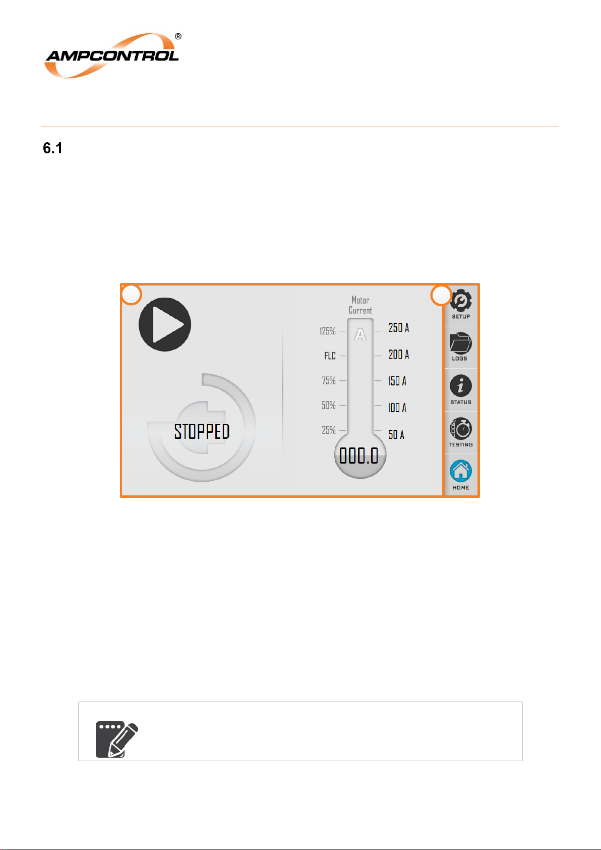
Ampcontrol Pty Ltd – ABN 28 000 915 542
ROCKSTARTER USER MANUAL
MAG-222 Version 2 – MARCH/19
Uncontrolled Copy - Refer to Ampcontrol Website for Latest Version
Page 38 of 127
APPROVED FOR EXTERNAL DISTRIBUTION
– PROPERTY OF AMPCONTROL PTY LTD
– NOT TO BE REPRODUCED IN PART
6 PRODUCT OPERATION
Interfacing Elements
The Rockstarter is controlled via the HMI. The system is menu driven and navigated via the 7.0 inch
capacitive-touch LCD display. The touchscreen provides an intuitive interface for viewing and modifying
the outlet’s configuration. All outlet control and protection settings are made through this interface. The
touchscreen can be operated while wearing gloves or using a stylus and will function (within reasonable
limits) with dirt and other contaminants on the screen.
The following sub-sections provide a brief overview of each of the interface elements. The HOME screen
is displayed in Figure 24 below.
1
2
Figure 24: Rockstarter UI Interface
There are a number of features identified in this image by numbered circles and detailed below.
Item 1 – Displays information that is relevant to the selected menu option/operating state.
Item 2 – Common to all views and displays the available menu options. The blue icon represents
the active menu option. Menu options include:
a. Home – For an overview of the HOME screen, refer to Section 6.1.1.
b. Testing – For an overview of the TESTING screen, refer to Section 6.1.2.
c. Status – For an overview of the STATUS screen, refer to Section 6.1.3.
d. Logs – For an overview of the Log screen, Refer to Section 6.5.
e. Setup – For an overview of the SETUP screen, refer to Section 6.1.4.
NOTE
After 15 minutes of inactivity on any menu option the display will revert
to the HOME screen. Any unsaved changes to the Rockstarter’s
configuration will be lost.
Page 39
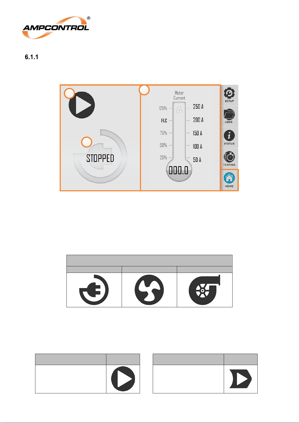
Ampcontrol Pty Ltd – ABN 28 000 915 542
ROCKSTARTER USER MANUAL
MAG-222 Version 2 – MARCH/19
Uncontrolled Copy - Refer to Ampcontrol Website for Latest Version
Page 39 of 127
APPROVED FOR EXTERNAL DISTRIBUTION
– PROPERTY OF AMPCONTROL PTY LTD
– NOT TO BE REPRODUCED IN PART
Home Interface
The HOME screen of the Rockstarter will appear similar to that of Figure 25 below. The interface has a
number of features which are identified in this image by numbered circles. Items identified in this figure
are detailed in the following subsections.
Figure 25: Rockstarter UI – Home Screen
6.1.1.1 Item 1: Outlet State
This will display an icon representing the current operating mode of the Rockstarter, as well as text
indicating the current operating state. The area underneath this section will display additional information
as required e.g. the trip type, pump sleep/blast detect is disabled etc. Table 4 provides an overview of
the icons used to indicate the Rockstarter’s operating modes.
Table 4: Outlet State
Mode of Operation
Outlet
Fan
Pump
6.1.1.2 Item 2: Outlet Control
The buttons displayed here are action buttons and allow for control of the Rockstarter. Refer to Table 5
for an overview of the buttons/icons.
Table 5: Outlet Control
Description
Icon Description
Icon
Start
Manual Start Override
1
3
2
Page 40
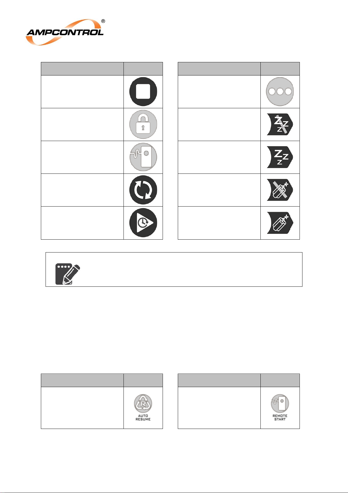
Ampcontrol Pty Ltd – ABN 28 000 915 542
ROCKSTARTER USER MANUAL
MAG-222 Version 2 – MARCH/19
Uncontrolled Copy - Refer to Ampcontrol Website for Latest Version
Page 40 of 127
APPROVED FOR EXTERNAL DISTRIBUTION
– PROPERTY OF AMPCONTROL PTY LTD
– NOT TO BE REPRODUCED IN PART
Description
Icon Description
Icon
Stop
System Undertaking
Check
Required Authorised Input
Disable Sleep
Remote Start
Enable Sleep
Reset
Disable Blast Detect
Delay Start
Enable Blast Detect
NOTE
If the Rockstarter is configured for remote start mode then the local start
button within the UI will be unavailable.
6.1.1.3 Item 3: Outlet Status and Trip Indication
The outlet status portion of the user interface will display the outlet current and the full load current set
point. This section will also indicate whether the outlet is configured for remote start, if auto resume is
active or if operating in LCM mode. Should a protection trip occur, this area of the display will indicate
the type of trip/s that are active. A more detailed description of the trip can be revealed by selecting the
trip message.
Table 6: Outlet Status Icons
Description
Icon Description
Icon
Auto Resume
Remote Start
Page 41
Ampcontrol Pty Ltd – ABN 28 000 915 542
ROCKSTARTER USER MANUAL
MAG-222 Version 2 – MARCH/19
Uncontrolled Copy - Refer to Ampcontrol Website for Latest Version
Page 41 of 127
APPROVED FOR EXTERNAL DISTRIBUTION
– PROPERTY OF AMPCONTROL PTY LTD
– NOT TO BE REPRODUCED IN PART
NOTE
The protection system constantly injects a test signal into outlets core
balance CT. The earth leakage on the outlet will read a small non-zero
value, even when the outlet is open. This confirms that the earth
leakage detection system is operational.
Table 7: Trip Messages
Category
Description
Message
Personnel Protection
Earth Leakage
Fault current detected above trip level, xxmA.
Measured value = xxmA
Earth Continuity Shunt
Pilot shunt resistance below trip level, 1.5kΩ.
Measured value = xxΩ
Earth Continuity Series
Pilot series resistance above trip level, xxΩ.
Measured value = xxΩ
Earth Fault Lockout
An Earth Fault has been detection on the load
side of the contactor.
Insulation Fault
An insulation fault has been detected on the load
side of the contactor.
Uncommanded Open
The contactor opened unexpectedly. Service
recommended.
Fail to Close
Contactor is reporting open while commanding it
closed.
Service recommended.
Loss of Vacuum
Detected xxV on the line while commanding the
contactor to open.
Service Recommended
Frozen Contactor
Contactor is reporting closed while commanding it
open.
Service recommended
Fast EC Trip
Shunt trip power supply failed. Service required.
Measured value = xxΩ
Fast EC Trip
Pilot series resistance above trip level
Remote Termination
Remote Termination Initialising
Remote Termination
Remote Termination device not detected
Remote Termination
Corrupt parameter settings detected
Remote Termination
Input 1 or 2 above trip setting xxx°C, Measured
value xxx°C
Remote Termination
Input 3, 4 or 5 above trip setting xxx°C, Measured
value xxx°C
Remote Termination
Stop Input Circuit input detected as open circuit
Remote Termination
Remote Termination device PTC Input detected
as open Circuit
Remote Termination
Remote Termination device communications fault
Load Protection
Start Block
If restart time is available:
“Motor too hot, thermal capacity xxx%. xx
minutes before restart allowed”
If not:
“Motor too hot. Thermal capacity xxx%. Restart
available at xx%”
Motor Overload
Motor too hot. Thermal capacity exceeded.
Short Circuit
Load current exceeded xxA for xxms.
Page 42
Ampcontrol Pty Ltd – ABN 28 000 915 542
ROCKSTARTER USER MANUAL
MAG-222 Version 2 – MARCH/19
Uncontrolled Copy - Refer to Ampcontrol Website for Latest Version
Page 42 of 127
APPROVED FOR EXTERNAL DISTRIBUTION
– PROPERTY OF AMPCONTROL PTY LTD
– NOT TO BE REPRODUCED IN PART
Category
Description
Message
Current Balance
Current imbalance detected above trip level, xx%.
Measured value xx%
Short Circuit
“Load current exceeded xxA for xxms, but did not
reach yyA” (where yy is the INST trip level)
Undervoltage
xxV detected on the line. Trip level < xxV.
Undercurrent
Current detected below trip level, xxA.
Measured value xxA
Outlet Control
Remote Start
There is a fault in the pilot circuit preventing the
100Ω start resistor being detected
Remote Start
Remote start button detected for more than 5
seconds after contactor closed.
General Fault
RFID Comms Failure
RFID Communications Fail, Please use external
lock button, cycle power/replace screen
electronics to resolve.
I2C connection failed
RKS Setting Dongle Fail, cycle power or replace
dongle to resolve
Shunt Trip Supply Fault
Shunt trip power supply failed. Service required.
System error
Protection Setting Memory Fault
The Earth Leakage CT cannot be detected
Internal Electronics Fault, Internal Logic Error.
Please cycle power to clear
Failed to detect coil supply voltage
Failed to maintain communications to protection
electronics
Protection Electronics CCM Fault
Protection Electronics Battery Fault
Volt charge failed. Service required
OTS mode ended
Circuit Breaker has opened
Internal Electronics Fault TM32
Internal Electronics Fault TM33
Internal Electronics Fault TM34
Internal Electronics Fault TM35
Internal Electronics Fault TM36
Internal Electronics Fault TM37
Testing Interface
The TESTING screen of the Rockstarter UI is shown in Figure 26 below. Authorised access is required
to operate the Rockstarter’s testing functions, refer to Section 6.1.6 for details on gaining authorised
access. This interface allows the user to select from the following tests:
Item 1 – Earth Leakage
Item 2 – Earth Continuity Series
Item 3 – Earth Continuity Shunt
Item 4 – Outlet Test System Tester (OTS)
Selecting an earth leakage or earth continuity test will return the user to the HOME page, the test
function will operate and should initiate an outlet trip with the appropriate trip message being displayed.
For details on resetting earth leakage and earth continuity trips, refer to Section 6.3. Refer to the
Page 43
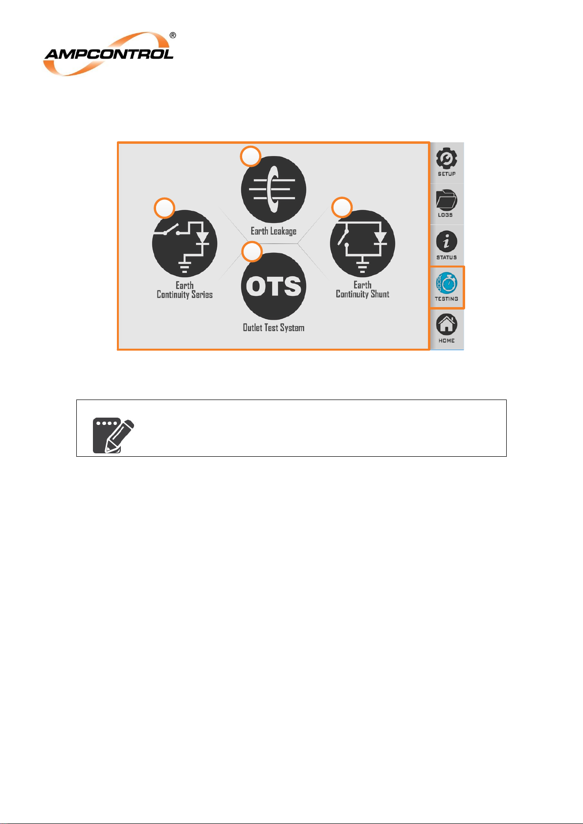
Ampcontrol Pty Ltd – ABN 28 000 915 542
ROCKSTARTER USER MANUAL
MAG-222 Version 2 – MARCH/19
Uncontrolled Copy - Refer to Ampcontrol Website for Latest Version
Page 43 of 127
APPROVED FOR EXTERNAL DISTRIBUTION
– PROPERTY OF AMPCONTROL PTY LTD
– NOT TO BE REPRODUCED IN PART
following section for details on the Outlet Test System. All test actions are logged.
Figure 26: Rockstarter UI – Testing Screen
NOTE
If Earth Continuity Protection is disabled, the earth Continuity Series
and Earth Continuity Shunt tests will not be available.
The Earth Leakage test button will energise until an earth leakage trip is detected and then turn off. If no
trip occurs for up to 1 seconds, the button will turn off and a trip will occur. Text in the bottom left of the
HOME screen will indicate if an EC test is active. Alternatively, if you enter the test page, the active
button will be blue.
The Earth Continuity test buttons will activate an open circuit (series test) or short circuit (shunt test) fault
indefinitely until the test button is manually turned off. This allows the pilot core to be isolated during
maintenance when the pilot detection voltage is needed to be removed.
The EC series test button has been linked to the circuit breaker operation such that opening the circuit
breaker also turn on the EC series test button. Closing the circuit breaker will turn off the EC series test
button. The EC series test button can be toggled when the circuit breaker is open to allow testing of the
EC circuit as desired.
1
2
3
4
Page 44
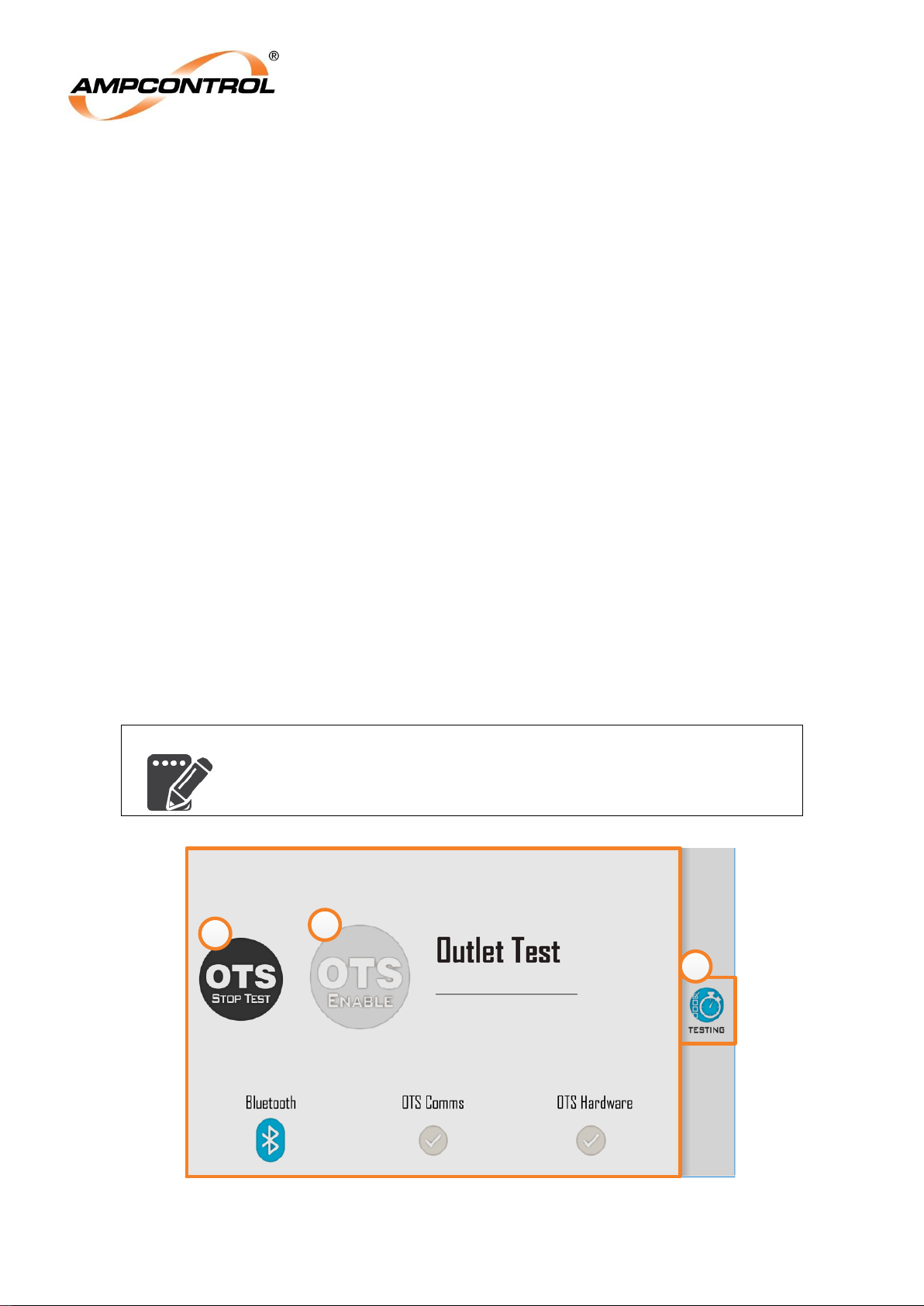
Ampcontrol Pty Ltd – ABN 28 000 915 542
ROCKSTARTER USER MANUAL
MAG-222 Version 2 – MARCH/19
Uncontrolled Copy - Refer to Ampcontrol Website for Latest Version
Page 44 of 127
APPROVED FOR EXTERNAL DISTRIBUTION
– PROPERTY OF AMPCONTROL PTY LTD
– NOT TO BE REPRODUCED IN PART
6.1.2.1 Outlet Test System (OTS)
Selecting the Outlet Test System will present the user with the interface similar to that shown in Figure
27. The “OTS Enable” button, item 2, allows the user to enable/disable the OTS testing mode. When the
Outlet Test System is enabled, the button will change to blue and the menu options on the right will
disappear (item 3), preventing the user from navigating away from the OTS page during testing.
Operation of the ‘OTS Enable’ button is logged. During testing, the OTS enable button will be locked out
(as shown in this image) and an “OTS STOP TEST” button (item 1) will appear, allowing the user to
abort the initiated OTS testing sequence.
The OTS testing interface can be entered in any system operating mode and does not require the
Rockstarter’s settings to be modified. The OTS Enable button is disabled during the following operating
conditions:
Fan delayed starts
Fan auto-restarts
Fan post-blast starts
Normal mode auto-restarts
Pump sleeps
Pump auto-restarts
OTS test mode will time out after 15 minutes of inactivity (no Bluetooth connection). A power cycle will
disable OTS test mode. At the conclusion of an OTS test sweep, the user will be presented with a
message prompting them to “Disable Testing & Exit”. This must be done before proceeding to normal
Rockstarter functionality. The lower portion of Figure 27 consists of three status indicators. The
functionality of these indicators is detailed in Table 8 below. When the Rockstarter’s earth continuity
protection is disabled the EC test should be unchecked within the OTS application. Otherwise the
Rockstarter will not trip on EC and the application will report a fault.
NOTE
If OTS test mode is disabled either due to user selection, time out or
power cycle all parameters will revert to their previous settings.
Figure 27: Rockstarter UI – Outlet Test System
in Progress
1
2
3
Page 45
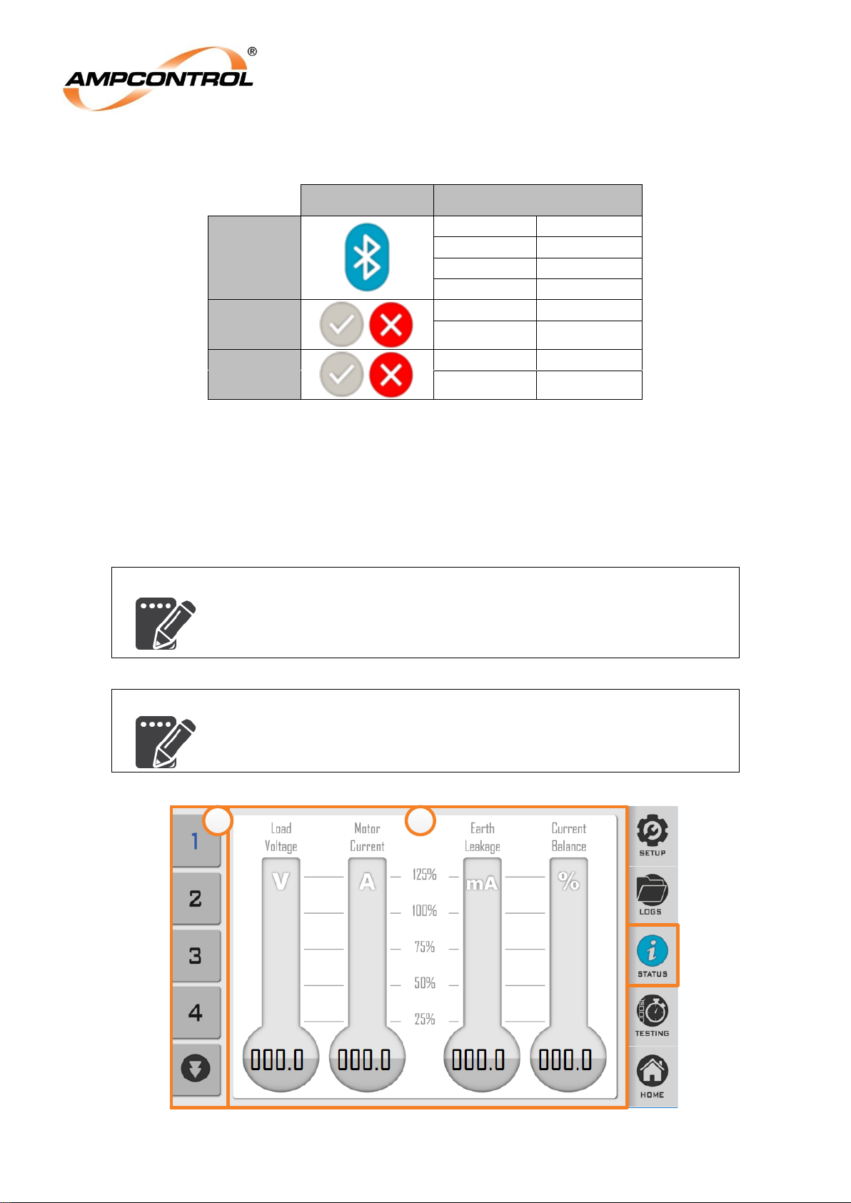
Ampcontrol Pty Ltd – ABN 28 000 915 542
ROCKSTARTER USER MANUAL
MAG-222 Version 2 – MARCH/19
Uncontrolled Copy - Refer to Ampcontrol Website for Latest Version
Page 45 of 127
APPROVED FOR EXTERNAL DISTRIBUTION
– PROPERTY OF AMPCONTROL PTY LTD
– NOT TO BE REPRODUCED IN PART
Table 8: OTS Status Symbols
Symbol
Description
Bluetooth
Solid Blue
Connected
Blue Flash
Advertising
Grey
Off
Red
Error
OTS
Comms
Grey Tick
Healthy
Red Cross
Fault
OTS
Hardware
Grey Tick
Healthy
Red Cross
Fault
An OTS test sweep may be performed as detailed in the OTS documentation with the following
exceptions:
OTS testing will not be allowed to proceed unless the Rockstarter’s OTS enable button has been
selected.
There is no ‘CONFIG’ option within the OTS application as it is automatically configured for use
with the Rockstarter.
NOTE
The Rockstarter is identified within the OTS application by the asset
number (if the OTS has been correctly configured) or serial number.
The Rockstarter’s serial number can be found on the name plate on the
front of the Rockstarter or on status page 4.
NOTE
The Rockstarter is only Compatible with version 3 or greater of the OTS
application.
Figure 28: Rockstarter UI – Status Screen
1 2
Page 46
Ampcontrol Pty Ltd – ABN 28 000 915 542
ROCKSTARTER USER MANUAL
MAG-222 Version 2 – MARCH/19
Uncontrolled Copy - Refer to Ampcontrol Website for Latest Version
Page 46 of 127
APPROVED FOR EXTERNAL DISTRIBUTION
– PROPERTY OF AMPCONTROL PTY LTD
– NOT TO BE REPRODUCED IN PART
Status Interface
The STATUS interface (Figure 28) displays an overview of the status of the outlet as well as system
information including serial numbers, hardware, software and firmware versions. The buttons located on
the left of the image (item 1) allow the user to navigate through the status pages. Refer to Table 9 for an
overview of the information contained within this menu. All pages from 7 onwards present raw data and
is anticipated for Ampcontrol diagnostic use.
Table 9: Status Page Overview
Page
Overview
Page
Overview
1
Average Load Voltage
Average Load Current
Earth Leakage Current
Current Balance
5
E-stop (from Protection [In]
CB status [In]
Reset Lock Input [In]
Shunt Voltage Status [In]
EL Routine Test [Out]
GPIO Connector – Start [In]
GPIO Connector – Stop [In]
GPIO Connector – Reset [In]
Delayed Start [In]
GPIO Connector – Run [Out]
OTS Tester Start [In]
OTS Tester Reset [In]
OTS Test Enable [Out]
2
Earth Continuity Shunt Resistance
Earth Continuity Series Resistance
Thermal Accumulator
Internal Temperature
6
Protection Outlet Parameter Status
Protection/LCM Load Parameter Status
UI System Parameter Status
UI Pump Parameter Status
UI Fan Parameter Status
LCM Name Parameter Status
UI Asset Parameter Status
3
Average Load Voltage
Average Load Current
Earth Leakage Current
Current Imbalance
Earth Continuity Series Resistance
Earth Continuity Shunt Resistance
Thermal Accumulator
Internal Temperature
CB Openings
MC Closures
7-17
Ampcontrol diagnostic use
4
Time
Rockstarter Serial Number
Protection Firmware Version
Display Firmware Version
Supervisor Firmware Version
OTS Firmware Version
Processor Image Version
Rockstarter HMI IP Address
Free Memory
Page 47

Ampcontrol Pty Ltd – ABN 28 000 915 542
ROCKSTARTER USER MANUAL
MAG-222 Version 2 – MARCH/19
Uncontrolled Copy - Refer to Ampcontrol Website for Latest Version
Page 47 of 127
APPROVED FOR EXTERNAL DISTRIBUTION
– PROPERTY OF AMPCONTROL PTY LTD
– NOT TO BE REPRODUCED IN PART
Setup Interface
The SETUP interface allows the user to configure all control and protection settings, refer to Figure 29.
This interface has a number of features identified in this image by numbered circles and detailed below.
The SETUP menu is navigated via the five options down the left hand side of the display with the blue
icon representing the active menu selection, refer to item 1. The outlet must be stopped before
parameters can be modified. If the outlet is running then only the current parameters may be viewed.
The following provides an overview of each of Setup menu options from top to bottom.
Outlet Control, refer to section 7.
o Mode of Operation (MO)
Outlet Control Mode
System Voltage
o Starting Options (SO)
Remote start at Machine
Restart After Power Cycle
Pilot Mode
(Fan Mode) Delayed Fan Start
(Fan Mode) Post-Blast Start
o (If in Pump or Fan Mode) Fan/Pump Mode Control (MC)
(Fan Mode) Burp Timing Mode
(Fan Mode) Burp Cycles
(Fan Mode) On Time
(Fan Mode) Off Time
(Fan Mode) Blast Pressure Level
(Pump Mode) Sleep Timing Mode
(Pump Mode) Snore Current
(Pump Mode) Sleep Time
o (If LCM Selected) LCM Parameters (LP)
LCM Name
RTD 1-2 Trip Level
RTD 3-5 Trip Level
RTD 1-2 Reset Level
RTD 3-5 Reset Level
Personnel Protection, refer to Section 8.
o Earth Continuity (EC)
Trip Time
Trip Level
Latching
o Earth Leakage (EL)
Trip Time
Trip Level
o Frozen Contact / Loss of Vacuum (FC)
Back EMF Time
Loss of Vacuum Level
Load Protection, refer to Section 9.
o Overload (OL)
Overload Model
Time Multiplier
Full Load Current (FLC)
Thermal Accumulator Start Block
(MOL) Model) Cooling Multiplier
o Short Circuit (SC)
Current Multiplier
Trip Time
Page 48
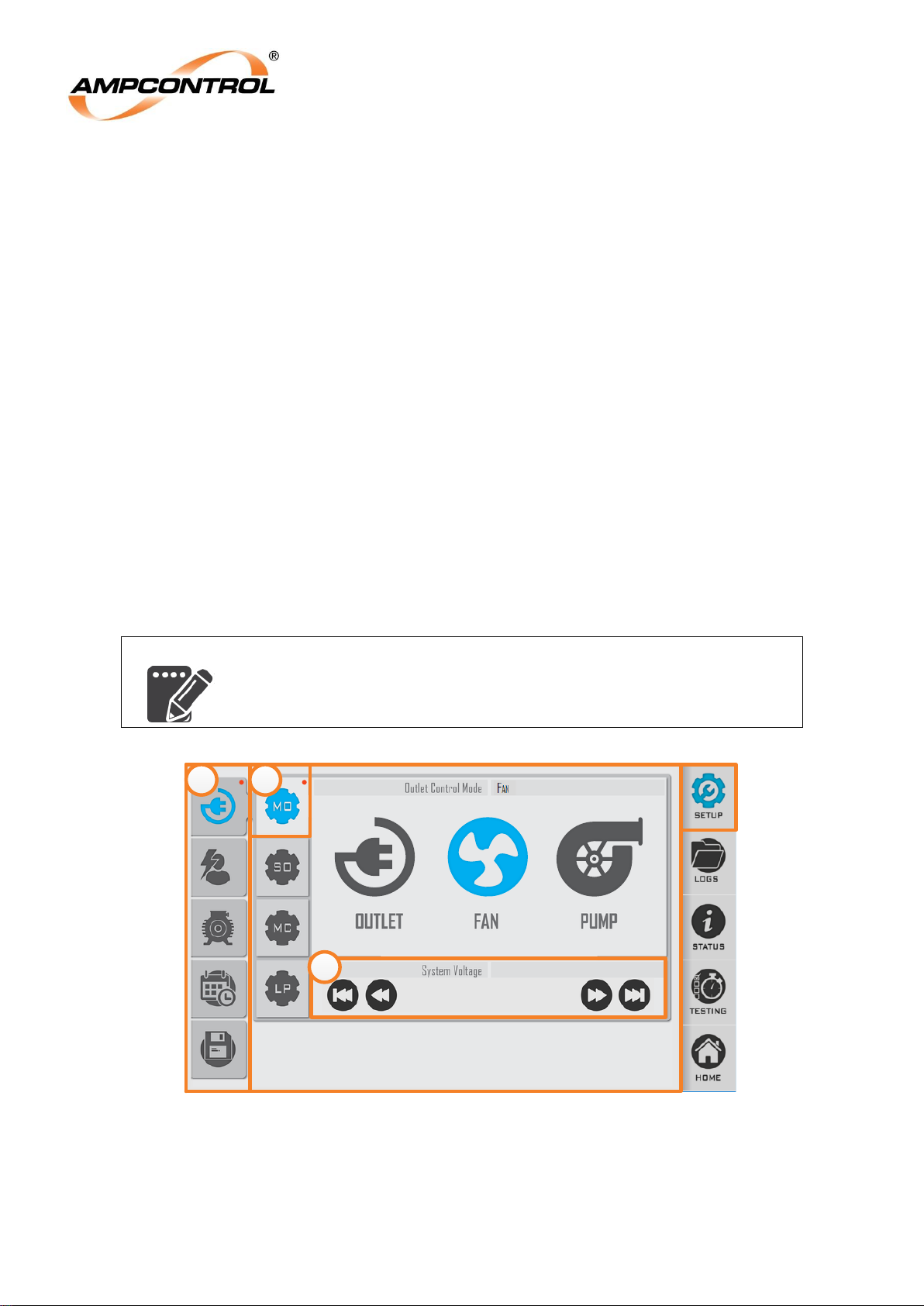
Ampcontrol Pty Ltd – ABN 28 000 915 542
ROCKSTARTER USER MANUAL
MAG-222 Version 2 – MARCH/19
Uncontrolled Copy - Refer to Ampcontrol Website for Latest Version
Page 48 of 127
APPROVED FOR EXTERNAL DISTRIBUTION
– PROPERTY OF AMPCONTROL PTY LTD
– NOT TO BE REPRODUCED IN PART
o Under Voltage (UV)
Trip Level
o Current Balance (CB)
Trip Level
o Under Current (UC) (Not available in Pump Mode)
Trip Level
General
o Asset Name (AN)
Asset Name
o Network Parameters (NP)
IP Address
Subnet Mask
Default Mask
Default Gateway
o Time (T)
Hour
Minute
o Date (D)
Day
Month
Year
Save Changes – changes must be saved before taking effect. Refer to Section 6.1.4.1.
NOTE
Parameters cannot be changed while the outlet is running. If the outlet
is running then only the current parameters may be viewed.
1000 Vac
690
1 2
3
Figure 29: Rockstarter UI – SETUP Page
Selecting the menu options on the left (item 1) reveals a secondary menu (item 2). The current outlet
settings are shown next to the heading for each setting option. Black text indicates that this is the current
setting stored on the Rockstarter while red text (item 3) indicates a parameter modification that has not
been saved. Parameter modifications are also indicated by a red dot in the top left hand corner of the
corresponding upper menu levels, refer to items 1 and 2.
Page 49
Ampcontrol Pty Ltd – ABN 28 000 915 542
ROCKSTARTER USER MANUAL
MAG-222 Version 2 – MARCH/19
Uncontrolled Copy - Refer to Ampcontrol Website for Latest Version
Page 49 of 127
APPROVED FOR EXTERNAL DISTRIBUTION
– PROPERTY OF AMPCONTROL PTY LTD
– NOT TO BE REPRODUCED IN PART
Certain parameters are linked and changing one will modify another. For instance, the UC trip point is
used as the snore current level when the Rockstarter is operating in Pump Mode. When this occurs the
modified parameters are indicated by “****” appearing in place of the red dot in the corresponding upper
menu levels.
NOTE
After 15 minutes of inactivity on any menu option the display will revert
to the HOME screen. Any unsaved changes to the Rockstarter’s
configuration will be lost.
6.1.4.1 Parameter Saving
Parameter saving requires authorisation to continue. All parameter changes are logged. Once
authorised, the parameter change acceptance time will vary depending on whether the Rockstarter is
operating in Diode of LCM Mode. When in Diode Mode the process is quicker that when operating in
LCM Mode. If the change occurred successfully, a message appears, then the UI changes to the Home
screen after 2 seconds.
If the Pilot Mode is being changed, no other parameters are permitted to be changed. Likewise, if any
other parameters are being modified, then the Pilot Mode cannot be changed.
For a Pilot Mode change, once the change has been verified, then the parameter sets for the new Pilot
Mode are loaded (e.g. if the Pilot Mode is changing from Diode to LCM mode, then all the LCM
parameters will need to be loaded into the Rockstarter).
When a parameter set is loaded, the parameter Invalid Masks are checked. If any UI parameter is
invalid, it will be added to a list (shown on status page 6), and a trip will be flagged. To make a
parameter ‘valid’ again, it can either be explicitly modified, or it will be set to its default value implicitly the
next time any other parameter value is changed (i.e. when the Save button is pressed).
Parameter sets will be reloaded at the following times:
At startup
When they have their values changed
After an internal Comms Fault is cleared
If the LCM is detached, and reattached (or a new one is attached)
Anytime that parameters are being changed or loaded/reloaded, then a “Parameter Syncing” message
will display on the Home screen. During this time no outlet starts will be allowed. After a power cycle, if
the UI detects that the protection parameters have changed, then any auto-restart is disabled. A log
message will appear to that effect.
Lighting and Indication
The Rockstarter incorporates LED lighting in the LCD surround to indicate the location and operating
state. The LEDs are very bright but dim upon touchscreen interaction. After 15 minutes of UI inactivity,
the lighting will revert to full brightness and the LCD will enter a sleep state. Should the LCD/LED panel
be damaged it may be replaced in-situ. For details on replacing the LCD/LED panel, refer to Appendix D.
The Rockstarter’s LED lighting will flash red/white under the following conditions:
Pre Starting System Check
During Pump Sleeping
In-between Fan Burps
During Fan Delayed Start Count Down
Auto-Restart Delay Count Down
Fan Post-Blast Delay Count Down
The remaining LED operation is detailed in Table 10.
Page 50
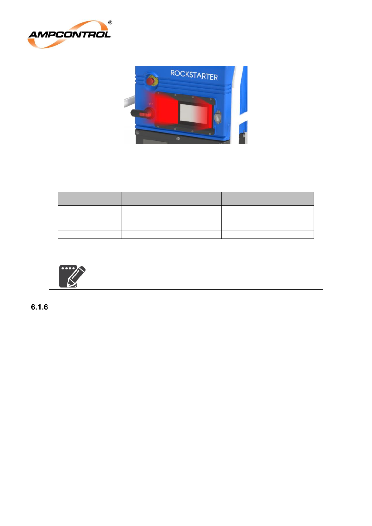
Ampcontrol Pty Ltd – ABN 28 000 915 542
ROCKSTARTER USER MANUAL
MAG-222 Version 2 – MARCH/19
Uncontrolled Copy - Refer to Ampcontrol Website for Latest Version
Page 50 of 127
APPROVED FOR EXTERNAL DISTRIBUTION
– PROPERTY OF AMPCONTROL PTY LTD
– NOT TO BE REPRODUCED IN PART
Figure 30: Rockstarter Lighting
Table 10: Rockstarter Lighting Overview
Screen Lighting
Single Flash
Solid
White – Running
Yellow
Failed NFC Action
Tripped
Red – Stopped
Blue
Successful NFC Action
–
NOTE
A failed NFC read while the unit is tripped will cause a temporary
dimming of the yellow LEDs.
RFID Authorisation & Lock Input
Certain functions of the Rockstarter may be accessed by general users while other functions require
authorisation. Authorisation on the Rockstarter is achievable from three inputs; a user trackable RFID
tag, the lock input switch, or over Modbus TCP.
To unlock the Rockstarter:
RFID Tag: Hold the RFID tag over the RFID reader
Lock Input: Activate the switch on the front of the unit, refer to Figure 2.
Modbus TCP: Send the appropriate control bit through communications.
A successful RFID read will be indicated by a blue flash while a failed tag read will be indicated by a
yellow flash. If there are trips present in the Rockstarter then the LEDs will be solid yellow. In this
situation a failed tag read will be indicated by the yellow LEDs will dimming momentarily. RFID
authorisation will time out after 30 seconds.
All authorisation events will be logged along with a time stamp, RFID authorisations will also log the
user’s ID.
RFID tags are factory programmed with user’s names stored on the tag. RFID tags require the
programming sheet completed on order, refer to Appendix E.
Page 51
Ampcontrol Pty Ltd – ABN 28 000 915 542
ROCKSTARTER USER MANUAL
MAG-222 Version 2 – MARCH/19
Uncontrolled Copy - Refer to Ampcontrol Website for Latest Version
Page 51 of 127
APPROVED FOR EXTERNAL DISTRIBUTION
– PROPERTY OF AMPCONTROL PTY LTD
– NOT TO BE REPRODUCED IN PART
Outlet Starting
To energise an outlet, the following start sequence will be followed:
If there are any active trips, the Rockstarter will ignore any start command received
If all trips are cleared, the Rockstarter will initiate a start sequence.
An earth fault lockout test is conducted. This test checks for a cable fault to earth. If the test fails,
the start sequence will be cancelled and the Rockstarter will report and earth fault lockout trip.
Attempt to close the Main Contactor. If the Main Contactor close was successful the Rockstarter
will be in a running state. If the close is not successful (Does not close within 5 seconds), a ‘close
fail’ trip will occur and the start sequence will be cancelled.
The Rockstarter will continue in the running state with the outlet closed until a stop command is
received or a protection function trips.
The Rockstarter now waits for the main contactor feedback to confirm that the main contactor has
closed. If this feedback is not detected within five seconds of close request, a ‘close fail’ trip will
occur and the start sequence will be cancelled.
If at any point during the start sequence a stop command is received or a protection function
trips, the start sequence is immediately cancelled and the Main Contactor (or Circuit Breaker) will
be opened.
In the event of any trip condition, the Rockstarter will trip the Main Contactor (or Circuit Breaker
as appropriate) and prevent the MC from closing until the fault condition has cleared and the trip
has been reset.
Outlet Resets
All resets in the Rockstarter are handled through the HMI. Most trips are reset with a general reset, not
requiring authorised access. Some trips require an authorised reset to provide a level of competency
associated with resetting faults. Authorisation is provided by way of a user trackable RFID tag (Section
6.1.6), the lock input on the front of the Rockstarter (Figure 2) or over the Modbus TCP communications
input.
The following latched trips may be cleared (once the fault has cleared) with a general reset:
Earth Continuity (EC)
Overload (OL)
Current Imbalance (CB)
Under Voltage (UV)
Under Current (UC)
Earth Fault Lockout (EFLO)
Remote start stuck
The following latched trips may be cleared only after authorised confirmation:
Earth Leakage (EL)
Earth Leakage CT detect (EL CT)
Main Contactor Faults
o Frozen Contact (FC)
o Loss of Vacuum (LOV)
o Fail to Close (FTC)
o Fail to Open (FTO)
Short Circuit (SC)
In the event of a MCF trip, Ampcontrol recommends the user performs an OTS test sweep to verify the
operation of the protection functions and contactor. If the contactor is faulty, remove the Rockstarter from
service and return the Rockstarter to Ampcontrol for inspection.
The following trip types will always latch (and require reset to continue): EL, ELCT, FC, SC, OL, UV,
Page 52
Ampcontrol Pty Ltd – ABN 28 000 915 542
ROCKSTARTER USER MANUAL
MAG-222 Version 2 – MARCH/19
Uncontrolled Copy - Refer to Ampcontrol Website for Latest Version
Page 52 of 127
APPROVED FOR EXTERNAL DISTRIBUTION
– PROPERTY OF AMPCONTROL PTY LTD
– NOT TO BE REPRODUCED IN PART
EFLO, Circuit Breaker and E-stop. The Circuit Breaker and E-Stop trips will require a mechanical reset of
the operator. Thermal Block trips will never latch. UC trips will latch only when the operating mode is
configured to Normal or Fan. In Pump Mode, UC faults are used for the pump run-dry detection. EC trips
will only latch when configured to do so.
A Circuit Breaker trip will also result in an EC Series trip on the pilot (when EC protection is enabled),
this aspect has been designed into the operation of the Rockstarter. As a result of the Circuit Breaker /
Pilot circuit interaction, as EC Series trip cannot be reset at the same time as the CB trip and will require
a second reset input.
NOTE
When resetting a Circuit Breaker trip the reset button must be pressed
twice.
Internal Trips
The Rockstarter has a number of trip functions that are not directly associated with the protection of the
outlet, but signal that an internal fault has been detected. If an internal trip is detected, contact
Ampcontrol for assistance.
In particular the following faults would require the Rockstarter to be returned for and inspection and
service:
Cable Connection Module Identification
MCF Battery Trip
o The Rockstarter has an internal battery. This is used to power the real time clock as well
as power the MCF latch. The health of this battery is monitored and if the battery
condition is failing this trip will be set.
Internal Logic Error
o This trip will be set in the event that an internal fault has been detected.
Event Log
The recorded event logs provide a history of the Rockstarters operation. A real time clock/calendar is
included, allowing each log to sequentially record the time, date and details of each event. A
chronological list of the previous 50 events is stored and is viewable from the HMI or over the
communications interface.
The following events are logged:
Table 11: Event Log Entry Types
Log ID
Event Text
0
"Event Code # Zero"
1
"Feed On"
2
"Insulation Test Record"
3
"Earth Leakage Trip"
4
"Series Earth Continuity Trip"
5
"Over current Trip"
Page 53

Ampcontrol Pty Ltd – ABN 28 000 915 542
ROCKSTARTER USER MANUAL
MAG-222 Version 2 – MARCH/19
Uncontrolled Copy - Refer to Ampcontrol Website for Latest Version
Page 53 of 127
APPROVED FOR EXTERNAL DISTRIBUTION
– PROPERTY OF AMPCONTROL PTY LTD
– NOT TO BE REPRODUCED IN PART
Log ID
Event Text
6
"Short Circuit INST Trip"
7
"Close Failed"
8
"Main Contactor Relay Closed"
9
"Under Current Trip"
10
"General Trip Reset"
11
"Power Down"
12
"Dongle Memory Error"
13
"Unexpected Restart"
14
"Frozen Contactor"
15
"Loss of Vacuum"
16
"Current Balance Trip"
17
"Thermal Memory Loss"
18
"Main Contactor Opened"
19
"LCM Memory Error"
20
"Shunt Earth Continuity Trip"
21
"Thermal Memory Reset"
22
"LCM Stop"
23
"LCM Off Line"
24
"Insulation Trip"
25
"LCM Communications Timeout"
26
"Power Up"
27
"Under Voltage Trip"
28
"Stopped"
29
"No Coil Voltage Trip"
30
“CT Detection Error"
31
"Remote Start Stuck"
32
"HMI Comms Timeout"
33
"Start Disabled"
34
"Earth Fault Lockout Trip"
35
"Unknown Restart Status"
Page 54
Ampcontrol Pty Ltd – ABN 28 000 915 542
ROCKSTARTER USER MANUAL
MAG-222 Version 2 – MARCH/19
Uncontrolled Copy - Refer to Ampcontrol Website for Latest Version
Page 54 of 127
APPROVED FOR EXTERNAL DISTRIBUTION
– PROPERTY OF AMPCONTROL PTY LTD
– NOT TO BE REPRODUCED IN PART
Log ID
Event Text
36
"Short Circuit Trip Reset"
37
"Earth Leakage Trip Reset"
38
"Fatal Clock Error"
39
"MCF Battery Under Voltage"
40
"Control Mask Changed"
41
"Invalid CCM"
42
"Internal Logic Error"
43
"Pos Temp Coefficient Trip"
44
"LCM Grp1 Temperature Trip"
45
"LCM Grp2 Temperature Trip"
46
"Short Circuit LT Trip"
47
"Charge Status Trip"
48
"VShunt Status Trip"
49
"Circuit Breaker Trip"
50
"Kill Switch Trip"
Time and date
The time and date are used only to time stamp the events in the log (which are recorded sequentially
regardless or the time and date). The time and data are not used for any control functions.
Modbus TCP
The implementation of Modbus TCP allows all Rockstarter data to be extracted, but has also
implemented inputs allowing for remote control over the outlet. This includes Starts, Stops, Resets and
Authorise inputs. See APPENDIX B: ROCKSTARTER MODBUS TCP for Modbus tables.
Remote Desktop Access
The Rockstarter has implemented Remote Desktop Protocol (RDP), this can be used to monitor control
and configure the Rockstarter remotely. The RDP will need to be used in conjunction with MODBUS
TCP to provide the Authorisation input. Any RDP software can be used by accessing the unit directly
through the configured IP address. To ensure there are no network conflicts each Rockstarter will need
to have the Network Settings manually configured initially.
NOTE
RDP Access Password:.Letmein
Page 55
Ampcontrol Pty Ltd – ABN 28 000 915 542
ROCKSTARTER USER MANUAL
MAG-222 Version 2 – MARCH/19
Uncontrolled Copy - Refer to Ampcontrol Website for Latest Version
Page 55 of 127
APPROVED FOR EXTERNAL DISTRIBUTION
– PROPERTY OF AMPCONTROL PTY LTD
– NOT TO BE REPRODUCED IN PART
7 OUTLET CONTROL
Outlet Configuration
The Outlet Control setup is accessed through the Mode of Operation (MO) menu, which allows for
configuration of the Rockstarters three modes (Normal, Fan and Pump) and system voltage. This must
be set in conjunction with the appropriate control supply termination, ensuring the outlet is correctly
configured for the system line voltage. Refer to Section 4.3.3 for details on the control supply termination
block.
Mode of Operation (MO)
o Outlet Control Mode
o System Voltage
NOTE
If earth continuity protection was disabled prior to changing the
Rockstarters mode of operation (Outlet, Pump, Fan), it will automatically
re-enable (with a trip time of 500ms) when the mode of operation is
changed.
In addition, the Outlet Control menu allows for configuration of the following:
Starting Options (SO) Three of the five options are available regardless of the outlet control
mode.
o Remote Start at Machine (For information, refer to Section 8.2.2)
o Restart after power cycle
o Pilot Mode – Diode or LCM
o (If in Fan Mode) Delayed Fan Start
o (If in Fan Mode) Post-Blast Start
Mode Control (MC) – If the outlet is configured in Fan Mode or Pump Mode, a third menu option
will allow for configuration of the burp and sleep functions, refer to Section 7.2 and Section 7.3,
respectively.
o (Fan Mode) Burp Timing Mode
o (Fan Mode) Burp Cycles
o (Fan Mode) On Time
o (Fan Mode) Off Time
o (Fan Mode) Blast Pressure Level
o (Pump Mode) Sleep Timing Mode
o (Pump Mode) Snore Current
o (Pump Mode) Sleep Time
LCM Parameters (LP) – If the pilot is configured for LCM termination, a fourth menu option will
allow for configuration of the LCM, refer to Section 0.
o LCM Name
o RTD 1-2 Trip Level
o RTD 3-5 Trip Level
o RTD 1-2 Reset Level
o RTD 3-5 Reset Level
Page 56
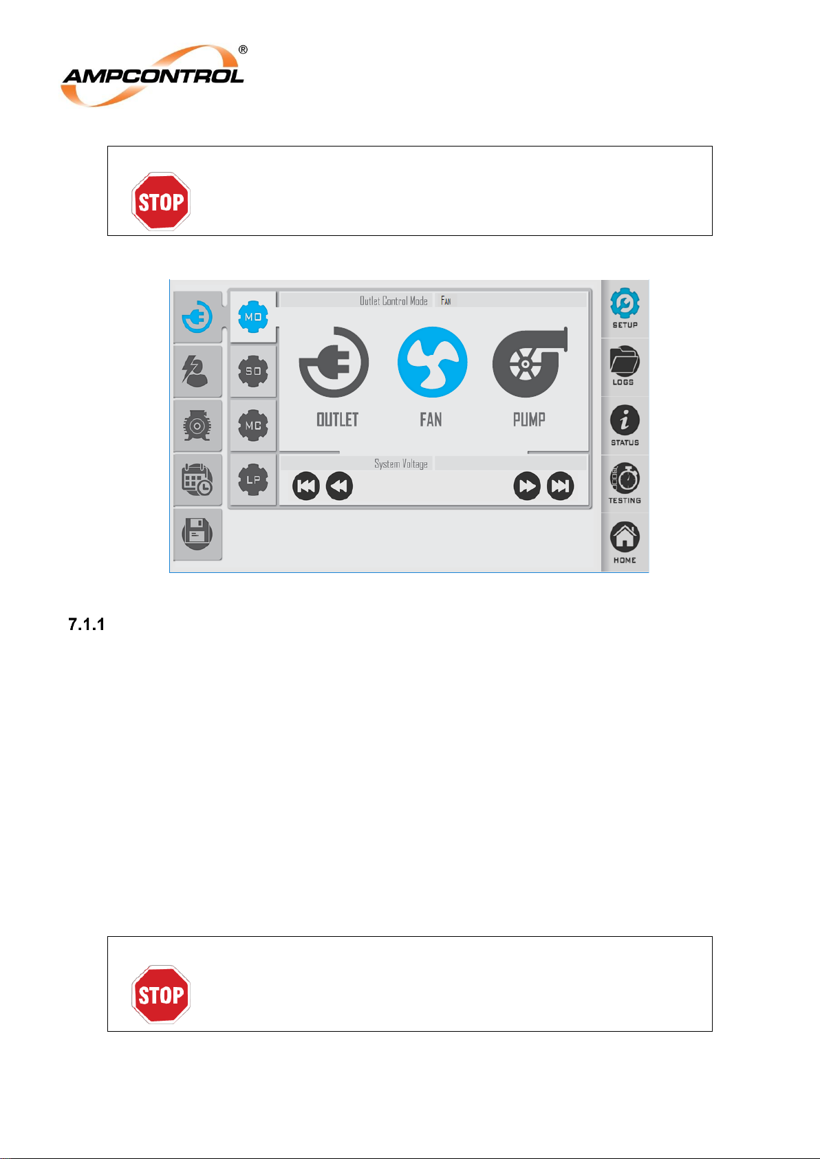
Ampcontrol Pty Ltd – ABN 28 000 915 542
ROCKSTARTER USER MANUAL
MAG-222 Version 2 – MARCH/19
Uncontrolled Copy - Refer to Ampcontrol Website for Latest Version
Page 56 of 127
APPROVED FOR EXTERNAL DISTRIBUTION
– PROPERTY OF AMPCONTROL PTY LTD
– NOT TO BE REPRODUCED IN PART
WARNING!
The system voltage must be set in conjunction with the appropriate
control supply termination, ensuring the outlet is correctly configured for
the system line voltage
1000 Vac
1000
Figure 31: Rockstarter UI – Mode Control
Restart after Power Cycle
It is possible to re-close the outlet after system power is restored from an outage. This function is called
“Restart after Power Cycle”, it is independent of the Pump or Fan Modes. If power is lost to the system
while the outlet is ‘Running’, the Rockstarter will restart the outlet when the power supply is restored,
allowing the operation to resume after the specified delay. This restart will only occur if all Rockstarter
prestart checks pass and the protection functions are healthy.
The Rockstarter is said to be ‘Running’ under the following conditions:
Main Contactor Closed in Normal Mode
Main Contactor Closed or during sleep cycle in Pump Mode
Main Contactor Closed or during burping when in Fan Mode
If the outlet has already been auto-restarted but is in the restart delay period, and another power
cycle occurs.
The Rockstarter will not auto-restart if a power cycle occurs while in the “Delayed Fan Start” or “PostBlast Start” delays.
WARNING!
If the Rockstarter is set to resume after a power failure, the outlet can
and will energise after a power outage if the system if healthy. All
operators should be aware of this.
This setting should be used with caution.
Page 57
Ampcontrol Pty Ltd – ABN 28 000 915 542
ROCKSTARTER USER MANUAL
MAG-222 Version 2 – MARCH/19
Uncontrolled Copy - Refer to Ampcontrol Website for Latest Version
Page 57 of 127
APPROVED FOR EXTERNAL DISTRIBUTION
– PROPERTY OF AMPCONTROL PTY LTD
– NOT TO BE REPRODUCED IN PART
LCM Input Configurations
When operating in LCM mode, it is possible to connect RTD input that can be monitored at the
Rockstarter. The LCM can be programmed with a name to allow it to be identified easier by the user.
This identifier can be up to 15 characters.
The RTD inputs are all individually monitored however there are only two trip levels that can be
configured with corresponding reset levels. RTD inputs 1 & 2 are grouped to one trip / reset setting, with
the remaining RTD inputs 3, 4 & 5 being grouped to the second trip / reset setting.
The trip levels can be set to any value 0-200°C with the corresponding reset value also being set to any
value 0-200°C.
For a reset to occur, all RTD inputs of that group need to be below the reset level.
Fan Control Mode
Due to the sudden and continuous pressure differential along the length of the airbag during initial
inflation, the walls of the bags can blow off or potentially rip, requiring downtime or costly repairs. The
Rockstarter’s Burp Mode manages this by pulsing the fan motor during start-up. This allows the pressure
in the bag to ramp in a controlled manner and inflate over a longer period of time.
Burp Control occurs on every start in fan mode. Burp Mode can be set from 0 to 4 cycles. If 0 cycles are
selected, then the Burp Mode will be disabled and the Rockstarter will not perform any pulsing of the fan
motor during start up, acting like a Direct Online (DOL) start. Both the ON and OFF periods are
configurable. After the Rockstarter completes the prescribed number of burp cycles, the fan motor will
run normally.
Fan Mode is a selectable operating mode of the Rockstarter that provides additional protection and
control functionality when the outlet is supplying fan motors. The Additional settings can be seen in Table
12. The setting are found in the Starting Options (SO) menu (Delay Fan Start, Post-Blast Start) and the
Fan/Pump Mode Control (MC) menu (Burp Timing Mode, Burp Cycles, Burp On Time, Burp Off Time,
Blast Pressure Level).
Page 58
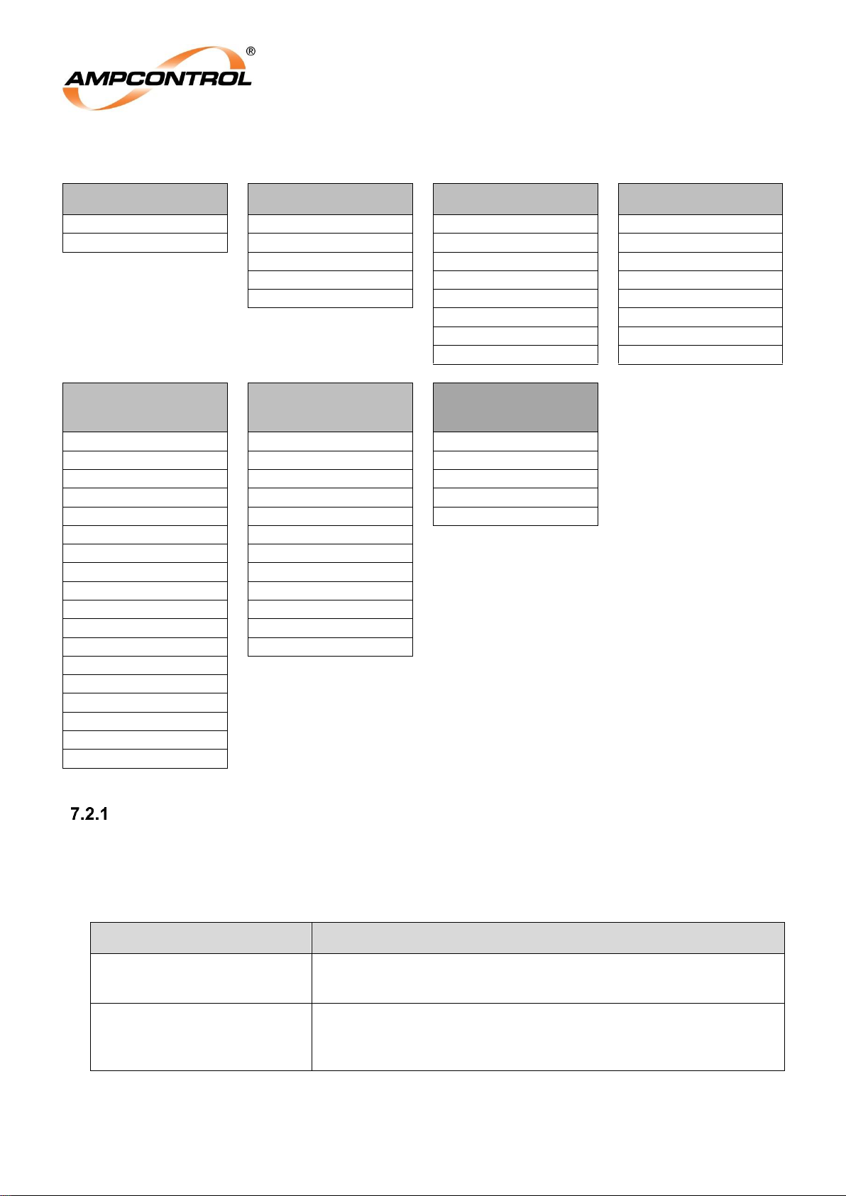
Ampcontrol Pty Ltd – ABN 28 000 915 542
ROCKSTARTER USER MANUAL
MAG-222 Version 2 – MARCH/19
Uncontrolled Copy - Refer to Ampcontrol Website for Latest Version
Page 58 of 127
APPROVED FOR EXTERNAL DISTRIBUTION
– PROPERTY OF AMPCONTROL PTY LTD
– NOT TO BE REPRODUCED IN PART
Table 12: Fan Protection – Configuration Settings
Burp Timing Mode
Burp Cycles
Burp On Time
Burp Off Time
Incremental
0
1 seconds
1 seconds
Fixed 1
2 seconds
2 seconds
2
3 seconds
3 seconds
3
4 seconds
4 seconds
4
5 seconds
5 seconds
10 seconds
10 seconds
15 seconds
15 seconds
20 seconds
20 seconds
Delayed Fan Start
Post Blast Start
Blast Pressure
Level
Off
0 minutes
2 kPa
0 minutes
0.5 minutes
4 kPa
1 minutes
1 minutes
6 kPa
2 minutes
2 minutes
8 kPa
3 minutes
3 minutes
10 kPa
4 minutes
4 minutes
5 minutes
5 minutes
10 minutes
10 minutes
15 minutes
15 minutes
20 minutes
20 minutes
25 minutes
30 minutes
30 minutes
60 minutes
45 minutes
60 minutes
75 minutes
90 minutes
105 minutes
120 minutes
Burp Timing Modes
The Rockstarter can be configured to two burp timing modes, fixed and incremental. These modes refer
to the length of time that the Rockstarter remains in the ON and OFF state each time that a burp event
occurs.
Table 13: Rockstarter Burp Timing Mode
Fan Burp Timing Mode
Description of Operation
Fixed
In Fixed Burp Timing Mode, the burping ON and OFF time will be
a fixed value for each burp cycle.
Incremental
In Incremental Burp Timing Mode each time that the Rockstarter
enters a consecutive burping cycle, the ON time will increase by
50% of the previous time. The OFF time remains constant.
Page 59
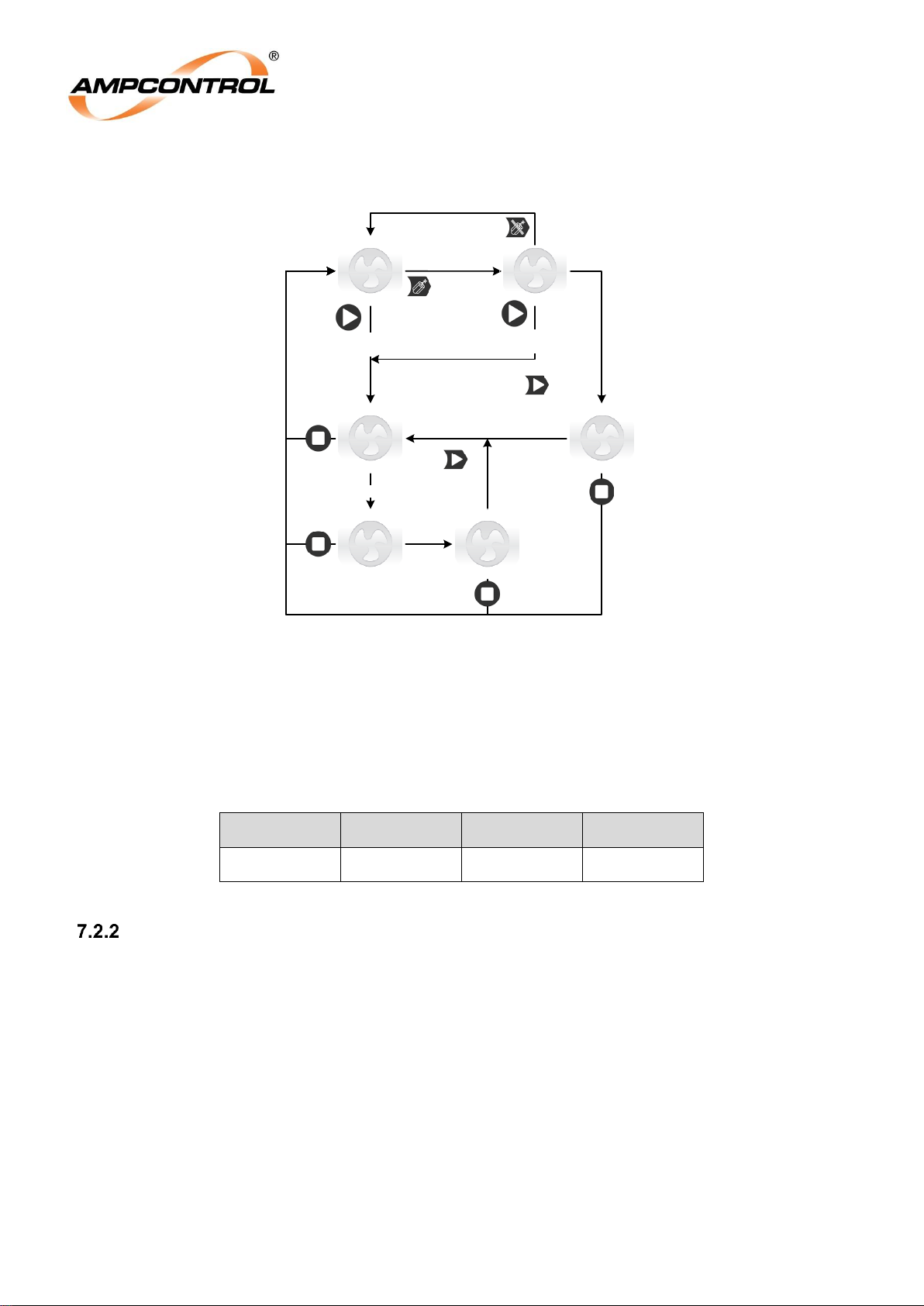
Ampcontrol Pty Ltd – ABN 28 000 915 542
ROCKSTARTER USER MANUAL
MAG-222 Version 2 – MARCH/19
Uncontrolled Copy - Refer to Ampcontrol Website for Latest Version
Page 59 of 127
APPROVED FOR EXTERNAL DISTRIBUTION
– PROPERTY OF AMPCONTROL PTY LTD
– NOT TO BE REPRODUCED IN PART
FAN MODE: Post Blast Start enabled,
Remote Start Disabled
Stopped
Burp #x
Running
Or Aux Start
Or Comms Start
Burp cycles complete
Post Blast Start
in x minutes
Or timeout
Or Aux Start
Or Comms Start
Or timeout
Or Aux Start
Or Comms Start
Blast
detected
Stopped,
waiting for blast
Or Aux Start
Or Comms Start
Auto Start in x
minutes
Auto Start
enabled,
power cycles
Figure 32: Starting Options - Post Blast Start Enabled, Remote Start Disabled
In the Incremental Timing Mode, the burp ON time increases as per the values shown in Table 14.
Table 14: Fan Incremental Timing Mode
Burp Cycle 1
Burp Cycle 2
Burp Cycle 3
Burp Cycle 4
Ton x 1
Ton x 1.5
Ton x 2.25
Ton x 3.375
Post-Blast Start
Post-Blast Start enables the Rockstarter to automatically start after detection of a blast event. Both the
time delay and blast pressure level are configurable. Post-Blast Start must be enabled within the UI and
enabled via the ‘Enable Blast Detect’ (refer to Section 6.1.1.2 for icon details) button on the Home
screen.
Page 60
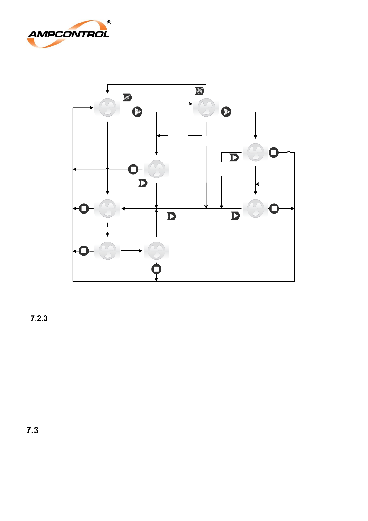
Ampcontrol Pty Ltd – ABN 28 000 915 542
ROCKSTARTER USER MANUAL
MAG-222 Version 2 – MARCH/19
Uncontrolled Copy - Refer to Ampcontrol Website for Latest Version
Page 60 of 127
APPROVED FOR EXTERNAL DISTRIBUTION
– PROPERTY OF AMPCONTROL PTY LTD
– NOT TO BE REPRODUCED IN PART
Stopped
Delayed Start in
x minutes
Burp #x
Running
Or Aux Delay Start
+ 75s debounce
Or timeout
Or Aux Start
Or Comms Start
Aux Start
Or Comms Start
Burp cycles complete
FAN MODE: Post Blast Start and Delay Start enabled,
Remote Start Disabled
Delayed Start in
x minutes,
waiting for blast
Or timeout
Or Aux Start
Or Comms Start
Post Blast Start
in x minutes
Or timeout
Or Aux Start
Or Comms Start
Blast
detected
Stopped,
waiting for blast
Aux Delay St
+ 75s DeBnc
Aux Start
Or Comms Start
Blast
Detected
Auto Start in x
minutes
Or timeout
Or Aux Start
Or Comms Start
Auto Start
enabled,
power cycles
Figure 33: Starting Options - Post Blast Start and Delayed Start Enabled, Remote Start Disabled
Delayed Start Input
In order to perform dual fan sequence starts with the Rockstarter, the ‘Run’ output of the first stage
Rockstarter controlled Fan (accessed through the Auxiliary I/O connector) must be connected to the
‘Delayed Start’ input of the second stage Rockstarter Fan. The ‘Delayed Fan Start’ function of the
Rockstarter must be enabled. This connection may be via the optional pre-terminated Fan Sequencing
cable or, alternatively through the I/O junction box and connecting cables, refer to the equipment list.
When the Rockstarter is configured for delayed starts, should the upstream Rockstarter stop/trip while
the downstream Rockstarter is in its delayed start countdown, the downstream Rockstarter will also stop.
There is a 75 second debounce on the auxiliary I/O delay start input. This is to accommodate for the
situation where the upstream Rockstarter may be burping, hence the run output will be on for a
maximum of 67.5 seconds plus a 7 second margin (achievable when in incremental Burp Timing Mode
Burp cycles is 4 and Burp on time is set to 20 seconds, 20 x 3.375).
Pump Control Mode – (Anti Snore Mode)
When the water being pumped, drops below the level of the pumps intake pipe, a mixture of air and
water is sucked into the pump. The sound that is produced when this occurs is known as snoring. As the
ratio of air to water increases, the load on the pump motor decreases. An insufficiently loaded pump will
run at the maximum rotor speed, potentially burning out the pump motor in as little as 30 seconds.
The Rockstarter’s Pump Sleep Mode provides protection against damage by initiating a sleep state when
the outlet current falls below a set level (Snore Current). After a user defined time period (Sleep Time),
Page 61
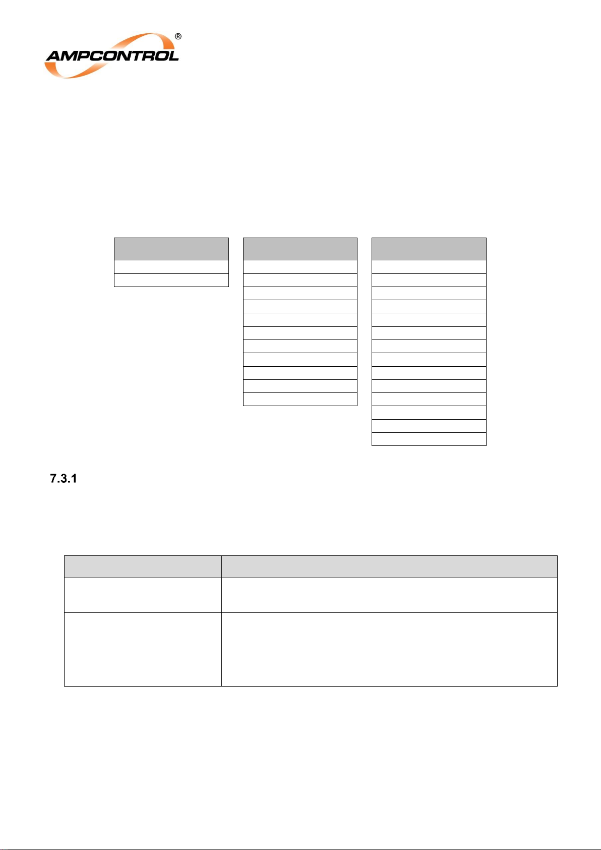
Ampcontrol Pty Ltd – ABN 28 000 915 542
ROCKSTARTER USER MANUAL
MAG-222 Version 2 – MARCH/19
Uncontrolled Copy - Refer to Ampcontrol Website for Latest Version
Page 61 of 127
APPROVED FOR EXTERNAL DISTRIBUTION
– PROPERTY OF AMPCONTROL PTY LTD
– NOT TO BE REPRODUCED IN PART
the Rockstarter will ‘wake’ the outlet to check if the intake pipe has been fully submerged again. If the
pump is still under-loaded, another sleep cycle will begin.
Pump Mode is a selectable operating mode of the Rockstarter that provides addition protection and
control functionality when the outlet is supplying pump motors. The additional setting can be seen in
Table 15. The additional settings are found in the Fan/Pump Mode Control (MC) menu (Sleep Timing
Mode, Snore Current and Sleep Time).
Table 15: Pump Protection – Configuration Settings
Sleep Timing Mode
Sleep Time
Snore Current
Incremental
0.5 minutes
30% FLC
Fixed
1 minutes
35% FLC
2 minutes
40% FLC
3 minutes
45% FLC
4 minutes
50% FLC
5 minutes
55% FLC
10 minutes
60% FLC
15 minutes
65% FLC
20 minutes
70% FLC
30 minutes
75% FLC
60 minutes
80% FLC
85% FLC
90% FLC
95% FLC
Sleep Modes
The Rockstarter can be configured to two timing modes, fixed and incremental. These modes refer to the
length of time that the Rockstarter remains in the sleep state each time that an undercurrent event
occurs.
Table 16: Rockstarter Pump Sleep Timing Mode
Pump Sleep Timing Mode
Description of Operation
Fixed
In Fixed Sleep Mode each time the Rockstarter enters a sleep
cycle, the sleep time will be a fixed value.
Incremental
In Incremental Sleep Mode each time that the Rockstarter enters
a consecutive sleep cycle, the sleep time will increase by 50%. If
water is present (current is above the Snore Current set-point)
when the pump wakes up, the sleep time will reset back to its
initial value.
In the Incremental Sleep Timing Mode, the consecutive sleep time increase as per the values shown in
Table 17.
After the Rockstarter has entered sleep mode four consecutive times, the sleep mode will no longer
increase and will remain constant at that duration.
Page 62
Ampcontrol Pty Ltd – ABN 28 000 915 542
ROCKSTARTER USER MANUAL
MAG-222 Version 2 – MARCH/19
Uncontrolled Copy - Refer to Ampcontrol Website for Latest Version
Page 62 of 127
APPROVED FOR EXTERNAL DISTRIBUTION
– PROPERTY OF AMPCONTROL PTY LTD
– NOT TO BE REPRODUCED IN PART
Table 17: Pump Incremental Timing Mode
Sleep Cycle 1
Sleep Cycle 2
Sleep Cycle 3
Sleep Cycle 4
Sleep Cycle 4
T
sleep
x 1
T
sleep
x 1.5
T
sleep
x 2.25
T
sleep
x 3.375
T
sleep
x 5.06
The Rockstarter is considered to have entered sleep mode consecutively if, after waking up from a sleep
state, the pump operates 5 seconds and does not exceed the specified Snore Current and therefore
returns to sleep. The Rockstarter will then initiate another sleep cycle and the consecutive sleep count
will increase.
This sleep count will reset under any of the following conditions:
The Snore Current level is exceeded
The pump is stopped/tripped
The pump is started with the start button
The Rockstarter loses power
NOTE
Undercurrent settings will not be visible when operating in Pump Mode
as the undercurrent trip point is used for the snore set-point. Disabling
pump sleep implicitly sets the undercurrent trip level to Off.
NOTE
When the Rockstarter enters a snore cycle in Pump Mode, it will log as
an undercurrent trip in the log list.
NOTE
If the pump is running with sleep disabled, when the Rockstarter screen
times out after 15min, Sleep mode will be re-enabled.
Page 63
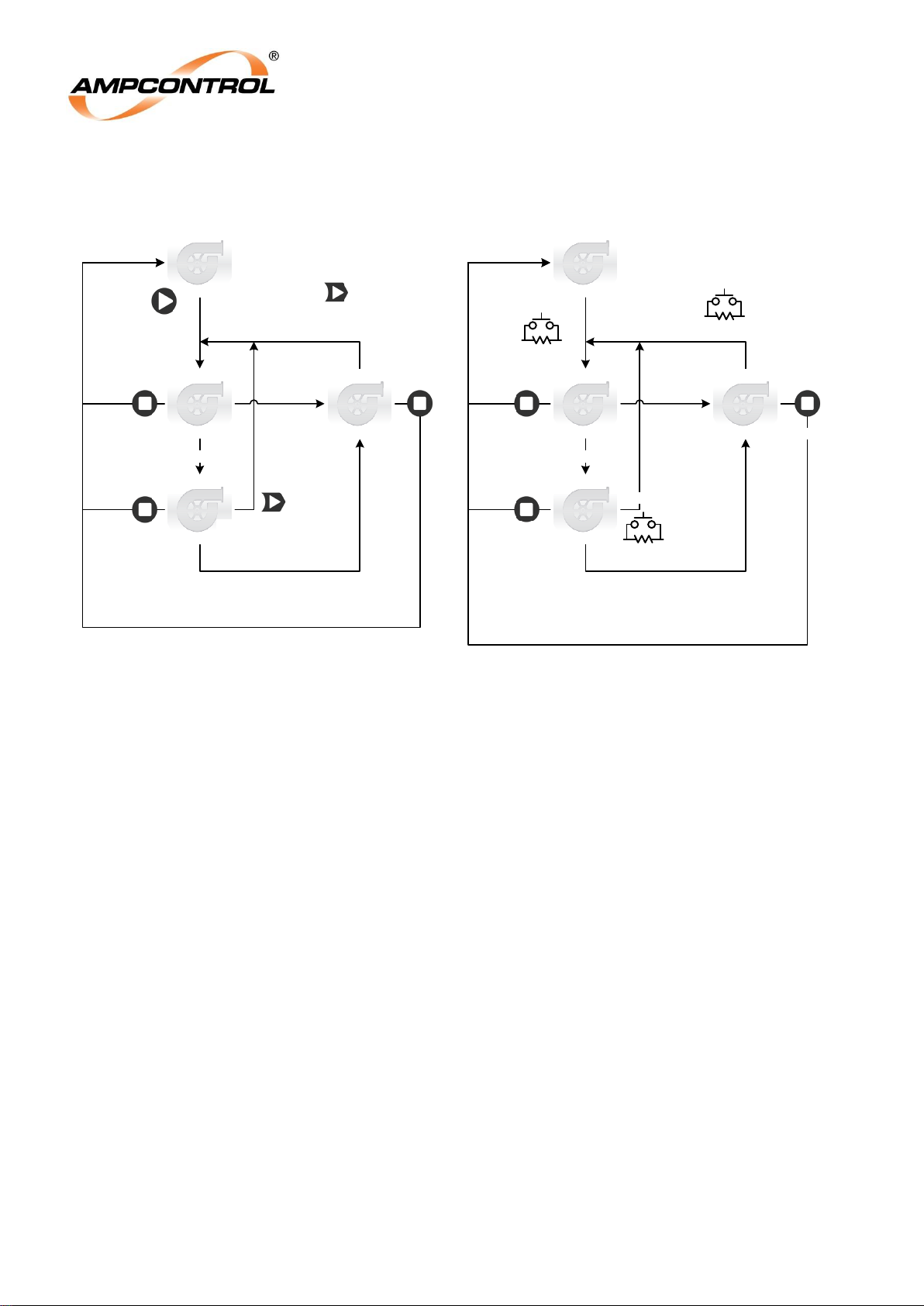
Ampcontrol Pty Ltd – ABN 28 000 915 542
ROCKSTARTER USER MANUAL
MAG-222 Version 2 – MARCH/19
Uncontrolled Copy - Refer to Ampcontrol Website for Latest Version
Page 63 of 127
APPROVED FOR EXTERNAL DISTRIBUTION
– PROPERTY OF AMPCONTROL PTY LTD
– NOT TO BE REPRODUCED IN PART
Stopped
Pump running
Pump Sleeping
for x minutes
Remote start
Pump runs dry
Or remote stop
Or remote stop
PUMP MODE: Remote Start enabled
Or timeout
Auto Start
enabled,
power cycles
Auto Start in x
minutes
Auto Start
enabled,
power cycles
Or timeout
Stopped
Pump running
Pump Sleeping
for x minutes
Or Aux Start
Or Comms Start
Pump runs dry
PUMP MODE: Remote Start disabled
Or timeout
Or Aux Start
Or Comms Start
Auto Start
enabled,
power cycles
Auto Start in x
minutes
Auto Start
enabled,
power cycles
Or timeout
Or Aux Start
Or Comms Start
Or remote stop
Figure 34: Starting Options – Pump Mode
Page 64
Ampcontrol Pty Ltd – ABN 28 000 915 542
ROCKSTARTER USER MANUAL
MAG-222 Version 2 – MARCH/19
Uncontrolled Copy - Refer to Ampcontrol Website for Latest Version
Page 64 of 127
APPROVED FOR EXTERNAL DISTRIBUTION
– PROPERTY OF AMPCONTROL PTY LTD
– NOT TO BE REPRODUCED IN PART
8 TOUCH POTENTIAL PROTECTION FUNCTIONS
The Rockstarter provides a number of protection functions that meet the requirements of the AS/NZS
2081 standard. These protection functions are:
Earth Leakage
Earth Continuity
Earth Fault Lockout
Main Contactor Fail
Earth Leakage
Trip Characteristics
Table 18: Earth Leakage Trip Characteristics
Parameter
Action
Frequency Range
Weighted Wideband, 5Hz-10kHz
Power Cycle
Trip status maintained
Reset
Requires an authorised reset after the trip condition has cleared
Trip Actions
Open Main Contactor
Prevent Main Contactor from closing
Active Period
Always active
Logging
Always logged
Monitoring
Earth Leakage current displayed as 0-125% of selected trip level
Trip Level (mA)
30, 100, 150, 200, 250, 300, 350, 400, 450, 500
Trip Time (ms)
Instant, 50, 100, 150, 200, 250, 300, 350, 400, 450, 500
Operation Summary
The earth leakage protection function utilises a core balance toroid to measure the earth fault current.
This function is tested to AS/NZS 2081:2011. The Rockstarter implements Ampcontrol’s weighted
wideband earth leakage protection function, which provides a scaled earth leakage response. This takes
into account the reduced sensitivity of the human body to touch potentials at higher frequencies. This
improved frequency discrimination also reduces the occurrence of nuisance trips.
When a fault occurs such that the trip level and time delays are exceeded a trip occurs. This trip opens /
prevents a close on the Main Contactor and is latched. An earth leakage trip is considered a special fault
and requires an authorised reset.
The status page Earth Leakage current (EL) is displayed the actual current value with the bar graph
visually showing the percentage compared to the trip level.
Page 65
Ampcontrol Pty Ltd – ABN 28 000 915 542
ROCKSTARTER USER MANUAL
MAG-222 Version 2 – MARCH/19
Uncontrolled Copy - Refer to Ampcontrol Website for Latest Version
Page 65 of 127
APPROVED FOR EXTERNAL DISTRIBUTION
– PROPERTY OF AMPCONTROL PTY LTD
– NOT TO BE REPRODUCED IN PART
Earth Leakage CT Failure Protection
Table 19: Earth Leakage CT Failure Trip Characteristics
Parameter
Action
Power Cycle
Trip status maintained
Reset
Requires a general reset after the trip condition has cleared
Trip Actions
Open Main Contactor
Prevent Main Contactor from closing
Active Period
Always active
Logging
Always logged
Monitoring
CT Detect trip status bit
Trip Time
500ms
The Rockstarter continuously monitors the integrity of the earth leakage detection circuit, as required by
AS/NZS 2081:2011, by passing a 15mA, 200Hz test signal through the primary of the earth leakage CT.
If the test signal is not detected by the Rockstarter a ‘CT Detection Error’ trip will occur. As the test signal
is always present, the display will constantly indicate an earth leakage level of approximately 15mA,
even when no actual earth leakage current is present. The test signal will also interact with earth leakage
currents and, depending on the frequency of the earth leakage current, create minor fluctuation in the
earth leakage value shown in the display.
The Earth Leakage CT Failure trip time is fixed at 500ms.
NOTE
The CT detection signal registers as a leakage current for the outlet
which is displayed on the main status even when the outlet is open.
Earth Continuity
This function monitors the continuity of the earth between the outlet and the machine, via the pilot core.
This is designed in accordance with AS/NZS 2081:2011. The Rockstarter measures the resistance of the
pilot-earth loop (Series) and the leakage between the pilot and earth conductors (Shunt). The series
detection is used to monitor the cables length and in turn touch potentials while the shunt measurement
ensures that a pilot to earth fault is detected.
If the pilot-earth loop is not healthy (series resistance greater or shunt resistance lower than their
respective trip settings) a trip occurs opening the main contactor. The trip can be configured as latching
or non-latching. This allows the user to determine if the trip is manually or automatically reset once the
pilot-earth loop is healthy.
The Rockstarter can be configured to operate in either Diode or LCM mode. This determines what
terminating device the Rockstarter is expecting on the pilot. When the Load Connection Module (LCM) is
terminated the pilot can also be used to transfer data for machine communications.
Page 66
Ampcontrol Pty Ltd – ABN 28 000 915 542
ROCKSTARTER USER MANUAL
MAG-222 Version 2 – MARCH/19
Uncontrolled Copy - Refer to Ampcontrol Website for Latest Version
Page 66 of 127
APPROVED FOR EXTERNAL DISTRIBUTION
– PROPERTY OF AMPCONTROL PTY LTD
– NOT TO BE REPRODUCED IN PART
NOTE
The LCM will only be recognised by the Rockstarter and will not be
seen as a suitable pilot termination by other earth continuity devices.
NOTE
If earth continuity protection was disabled prior to changing the
Rockstarters mode of operation (Outlet, Pump, Fan), it will automatically
re-enabled (with a trip time of 500ms) when the mode of operation is
changed.
CAUTION!
Cable parameters are important to the correct operation of the Pilot
E/C function. Ampcontrol recommends the use of symmetrical cables to
eliminate induced voltage on the pilot conductor from the power
conductor.
Pilot Series Trip Characteristics
Table 20: Earth Continuity Series Trip Characteristics
Parameter
Action
Power Cycle
Trip status maintained
Reset
Requires a general reset (latched mode) or Automatically resets (nonlatching mode) after the trip condition has cleared.
Trip Actions
Open Main Contactor
Prevent Main Contactor from closing
Active Period
Can be disabled through the HMI for installations no requiring EC
protection
Logging
Logged only if outlet is running
Monitoring
Available as the raw ohms measurement, resolution of 1Ω.
Trip Time (ms)
100, 150, 200, 300, 400, 500, Off
Trip Level (Ω)
10, 15, 20, 25, 30, 35, 40, 45
Latch
On, Off
Remote Start
On, Off
Page 67
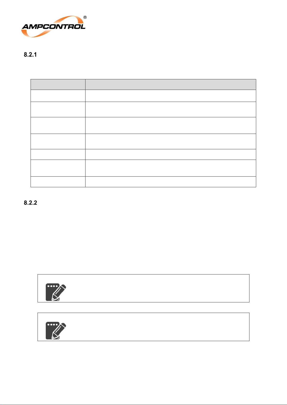
Ampcontrol Pty Ltd – ABN 28 000 915 542
ROCKSTARTER USER MANUAL
MAG-222 Version 2 – MARCH/19
Uncontrolled Copy - Refer to Ampcontrol Website for Latest Version
Page 67 of 127
APPROVED FOR EXTERNAL DISTRIBUTION
– PROPERTY OF AMPCONTROL PTY LTD
– NOT TO BE REPRODUCED IN PART
Pilot Shunt Trip Characteristics
Table 21: Earth Continuity Shunt Trip Characteristics
Parameter
Action
Power Cycle
Trip status maintained
Reset
Requires a general reset (latched mode) or Automatically resets (nonlatching mode) after the trip condition has cleared.
Trip Actions
Open Main Contactor
Prevent Main Contactor from closing
Active Period
Can be disabled through the HMI for installations no requiring EC
protection
Logging
Always logged
Parameters
Trip time
Trip latch enable
Monitoring
Available as the raw ohms measurement, resolution of 100Ω.
Remote Start
Remote start mode can be used to allow the start sequence to be initiated from the load via a pilot core.
In remote start mode, comms sources cannot force the start of the outlet. They can however prevent the
outlet from starting.
In Diode mode: Remote start is implemented with a 100Ω resistor (1% 5W) connected in series
with the pilot circuit and a normally open pushbutton connected in a parallel to this resistor. The
loop resistance of the circuit will then be 100Ω plus the resistance of the pilot-earth loop.
In LCM mode: Remote start is implemented through a normally open pushbutton connected to
the “Start Input” of the LCM.
NOTE
Remote starts will not be possible when earth continuity protection is
disabled, regardless of the pilot termination mode.
NOTE
If the Rockstarter is configured for remote start then the local start
button within the UI will be unavailable.
The remote start setting requires the following sequence for a start to be triggered:
Diode Mode:
1. The Rockstarter must be healthy and ready to start, all trips must be clear.
2. The Rockstarter’s earth continuity protection and remote start function must be enabled.
Page 68
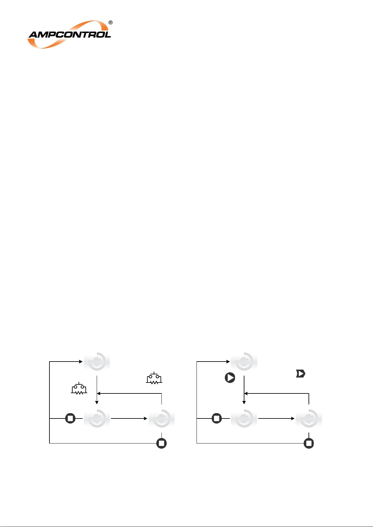
Ampcontrol Pty Ltd – ABN 28 000 915 542
ROCKSTARTER USER MANUAL
MAG-222 Version 2 – MARCH/19
Uncontrolled Copy - Refer to Ampcontrol Website for Latest Version
Page 68 of 127
APPROVED FOR EXTERNAL DISTRIBUTION
– PROPERTY OF AMPCONTROL PTY LTD
– NOT TO BE REPRODUCED IN PART
3. The pilot resistance must be detected above 90Ω to ensure that a start resistor is in place.
4. As soon as the 100Ω resistance is shorted a start is triggered.
(Note that the EC series protection function will still be operating, and the start will not be
triggered if the EC measurement is above the EC trip level).
5. If the EC resistance falls below 90Ω, but remains above the EC series threshold it will result in a
remote start error trip after 1 second.
6. The start sequence (EFLO, MC closing) starts immediately after the trigger.
7. The start resistor must remain shorted out by the start button for the duration of the pre-start
tests.
8. If the EC resistance does not return to above 90Ω within 5 seconds after the outlet closes, the
Rockstarter will trip on ‘Remote Start Stuck’.
9. The Remote Start Fault is automatically reset once the EC resistance return to above 90Ω. (An
external reset is not required)
If the earth continuity trip is set to non-latching, the “Start Timed Out” fault will automatically reset once
the start resistor is detected (a manual reset is not required).
LCM Mode:
1. The Rockstarter must be healthy and ready to start, all trips must be clear.
2. The Rockstarter’s earth continuity protection and remote start function must be enabled.
3. The communications between the Rockstarter and LCM must be healthy.
4. As soon as the start input is shorted a start is triggered.
5. The start sequence (EFLO, MC closing) starts immediately after the trigger.
6. The start resistor does not need to remain shorted out by the start button for the duration of the
pre-start tests. This input is edge triggered, it can be held closed or released.
7. There is no ‘Remote Start Stuck” trip in LCM Mode as the start is initiated through the LCM and
does not affect the pilot circuit.
Stopped
Outlet running
Or Aux Start
Or Comms Start
NORMAL MODE: Remote Start disabled
Auto Start in x
minutes
Auto Start
enabled,
power cycles
Or timeout
Or Aux Start
Or Comms Start
Stopped
Outlet running
Remote start
Or remote stop
NORMAL MODE: Remote Start enabled
Auto Start in x
minutes
Auto Start
enabled,
power cycles
Or timeout
Or remote stop
Figure 35: Starting Options - Normal Mode
Page 69
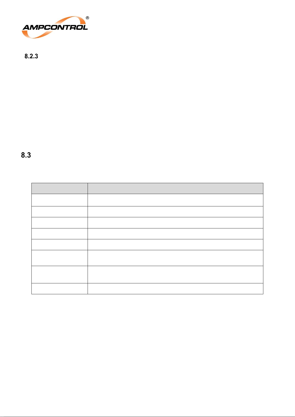
Ampcontrol Pty Ltd – ABN 28 000 915 542
ROCKSTARTER USER MANUAL
MAG-222 Version 2 – MARCH/19
Uncontrolled Copy - Refer to Ampcontrol Website for Latest Version
Page 69 of 127
APPROVED FOR EXTERNAL DISTRIBUTION
– PROPERTY OF AMPCONTROL PTY LTD
– NOT TO BE REPRODUCED IN PART
Remote Stop
Remote stops can be utilised in any mode of operation, it does not require Remote Start Mode to be
active. This allows for outlet stops to be initiated from the load via a pilot core. Regardless of the mode of
operation, a stop can be initiated from any source (HMI, Remote, AUX, Modbus TCP, and Remote
Desktop) and will prevent the outlet from starting.
In Diode mode: Remote stop button can be implemented by installing a normally closed pushbutton in
series with the pilot conductor. When the pushbutton is pressed it will create an open circuit on the pilot
line causing an earth continuity trip.
If earth continuity is not set to latch, the Rockstarter can be started and stopped at the motor enclosure.
If earth continuity is set to latch, a reset must be performed before the outlet can be started again.
In LCM mode: Remote stop is implemented through a normally closed push button connected to the
“Stop Input” of the LCM. If not being used this input need to be shorted out to prevent a stop being
initiated.
Earth Fault Lockout
Table 22: Earth Fault Lockout Trip Characteristics
Parameter
Action
Power Cycle
Trip status maintained
Reset
Requires a general reset
Trip Actions
Prevent Main Contactor from closing
Active Period
Single test performed during the start sequence
Logging
Logged when test fails
Monitoring
Last test value stored, for each phase. Value stored is from 0-150%,
where 100% is 3MΩ
Trip Level
3PH Load Disconnected – Trip by 3MΩ
3PH Load Connected – Trip by 1MΩ
Test Time
2 seconds
The earth fault lockout function tests the resistance of the three phase lines to earth. The Rockstarter
applies an extra low voltage signal prior to the closure of the main contactor in accordance with AS/NZS
2081:2011. The test is automatically initiated by a starting sequence once all starting conditions are met.
This test takes 2 seconds. When the impedance of any of the phase conductors falls below the tripping
threshold a trip occurs.
The EFLO trip point has been chosen to ensure compliance to the worst case scenario as defined in
AS/NZS 2081:2011 section 7.2.
“Earth fault lockout protection devices shall be designed to prevent energization of the circuit interrupting
device when the insulation resistance of any active conductor to earth is below 1 MΩ. This requirement
shall apply to any combination of active conductors to earth”
To ensure compliance with AS/NZS 2081:2011, the EFLO set point is influenced by the configuration
that reduces the impedance to earth the greatest. This being all three phases shorted together through a
load or connected motor, essentially causing all three phase leakage impedance’s to be paralleled. An
Page 70
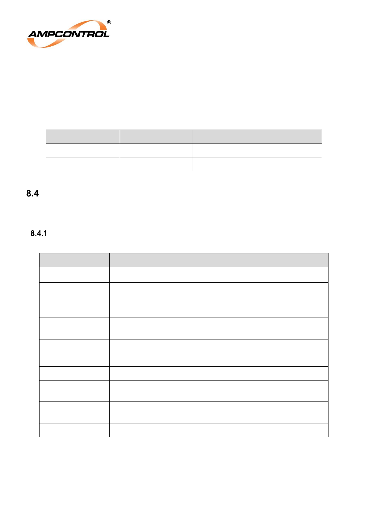
Ampcontrol Pty Ltd – ABN 28 000 915 542
ROCKSTARTER USER MANUAL
MAG-222 Version 2 – MARCH/19
Uncontrolled Copy - Refer to Ampcontrol Website for Latest Version
Page 70 of 127
APPROVED FOR EXTERNAL DISTRIBUTION
– PROPERTY OF AMPCONTROL PTY LTD
– NOT TO BE REPRODUCED IN PART
electric motor or load can be treated as a short circuit for the applied DC test voltage. Under this
circumstance the Rockstarter needs to trip before it detects 1MΩ to ensure compliance.
The individual leakage impedances for each phase is an un-shorted configuration (due to load or motor)
is then required to be greater that 3MΩ to ensure the minimum level of safety is maintained.
Table 23: EFLO Trip Threshold
EFLO Trip Threshold
Outlet Configuration
Example
1Meg
Load on Outlet
Outlet cable terminated by Motor
3Meg
Open Circuit
Outlet Shuttle car with incomer contactor
Main Contactor Protection
There are four main contactor protection functions. Each of the functions monitors the states of the
outlets main contactor. If a fault is detected, the circuit breaker is opened in order to remove power from
the potentially faulty contactor.
Load Side Voltage Detection (Loss of Vacuum)
Table 24: Voltage Detection Trip Characteristics
Parameter
Action
Power Cycle
Trip status maintained
Reset
Requires an authorised reset. Note: The condition of the contactor is
required to be investigated and documented. Ampcontrol recommends
performing a controlled start and stop prior to returning to service. A
detailed statutory test record in generated by the OTS application.
Trip Actions
Open Circuit Breaker
Prevent Main Contactor from closing
Active Period
When outlet is not energised and the Back EMF timer has expired.
Logging
Logged when a trip occurs
Monitoring
Phase voltages are continuously updated.
Back EMF Time
(sec)
2, 5, 10, 15, 20
Loss of Vacuum
Level (VAC or VDC)
25, 50, 100, 150
Trip Time
< 1 Second
The Loss of Vacuum trip in the Rockstarter acts like a Main Contactor Fail Electrical trip. Loss of Vacuum
detection provides protection against a faulty contactor that has failed due to ionisation between the
contacts (or welded contacts) causing voltage to be detected on the output when the contactor is open.
The voltage level at which the main contactor failure protection should be initiated is outlined in AS/NZS
2081:2011 Clause 9.2.1, being 25VAC or 60VDC or up to 10% of the system voltage.
Page 71
Ampcontrol Pty Ltd – ABN 28 000 915 542
ROCKSTARTER USER MANUAL
MAG-222 Version 2 – MARCH/19
Uncontrolled Copy - Refer to Ampcontrol Website for Latest Version
Page 71 of 127
APPROVED FOR EXTERNAL DISTRIBUTION
– PROPERTY OF AMPCONTROL PTY LTD
– NOT TO BE REPRODUCED IN PART
If the LOV setting is set about the voltage level defined by AS/NZS 2081:2011, the protection scheme
will no longer be compliant to the standard. Users are required to be diligent in the configuration of the
settings to ensure the Rockstarter remains compliant to the relevant standards. The voltage setting is for
both AC and DC voltages, a setting of 25V will trip from 25VAC to 25VDC.
The loss of vacuum protection cannot be enabled immediately after the outlet is stopped as there is the
potential for back EMF from the load to cause a nuisance trip. Subsequently, a back EMF timer is
provided and allowed to elapse after the outlet has stopped, before the Loss of Vacuum protection can
be operated.
Frozen Contactor
Table 25: Frozen Contactor Trip Characteristics
Parameter
Action
Power Cycle
Trip status maintained
Reset
Requires an authorised reset. Note: The condition of the contactor is
required to be investigated and documented. Ampcontrol recommends
performing a controlled start and stop prior to returning to service. A
detailed statutory test record in generated by the OTS application.
Trip Actions
Open Circuit Breaker
Prevent Main Contactor from closing
Active Period
When outlet is not running
Logging
Always
Monitoring
None
Trip Time
100ms
The Frozen Contactor trip in the Rockstarter acts like a main contactor fail logical trip. If the Rockstarter
detects that the main contactor has closed when requested to be open, or remains closed after
requested to open, it will result in a frozen contactor trip, tripping the circuit breaker.
The frozen contactor protection activates in approximately 100ms.
Page 72
Ampcontrol Pty Ltd – ABN 28 000 915 542
ROCKSTARTER USER MANUAL
MAG-222 Version 2 – MARCH/19
Uncontrolled Copy - Refer to Ampcontrol Website for Latest Version
Page 72 of 127
APPROVED FOR EXTERNAL DISTRIBUTION
– PROPERTY OF AMPCONTROL PTY LTD
– NOT TO BE REPRODUCED IN PART
Close Fail
Table 26: Contactor Close Fail Trip Characteristics
Parameter
Action
Power Cycle
Trip status maintained
Reset
Requires an authorised reset. Note: The condition of the contactor is
required to be investigated and documented. Ampcontrol recommends
performing a controlled start and stop prior to returning to service. A
detailed statutory test record in generated by the OTS application.
Trip Actions
Open Circuit Breaker
Prevent Main Contactor from closing
Active Period
After closing MCR, prior to receiving confirmation from the MCI
Logging
Always
Monitoring
None
Trip Time
1 second
Close fail detects the event when the Rockstarter attempts to close the main contactor but receives no
confirmation of the close via the contactor feedback. As a result, the Rockstarter will trip the circuit
breaker.
Close fail protection activates in approximately 1 second.
External Open
Table 27: External Open Trip Characteristic
Parameter
Action
Power Cycle
Trip status maintained
Reset
Requires an authorised reset. Note: The condition of the contactor is
required to be investigated and documented. Ampcontrol recommends
performing a controlled start and stop prior to returning to service. A
detailed statutory test record in generated by the OTS application.
Trip Actions
Open Circuit Breaker
Prevent Main Contactor from closing
Active Period
While running
Logging
Always
Monitoring
None
Trip Time
1 second
An external open trip occurs if the main contactor is detected as having been opened while the system is
in run mode.
External open protection activates in approximately 1 second.
Page 73
Ampcontrol Pty Ltd – ABN 28 000 915 542
ROCKSTARTER USER MANUAL
MAG-222 Version 2 – MARCH/19
Uncontrolled Copy - Refer to Ampcontrol Website for Latest Version
Page 73 of 127
APPROVED FOR EXTERNAL DISTRIBUTION
– PROPERTY OF AMPCONTROL PTY LTD
– NOT TO BE REPRODUCED IN PART
Coil Voltage Detection
Table 28: Coil Voltage Detection Trip Characteristics
Parameter
Action
Power Cycle
–
Reset
Automatic
Trip Actions
Open Circuit Breaker
Prevent Main Contactor from closing
Active Period
Always
Logging
Only logged if it results in the protection module stopping a running
outlet
Monitoring
Coil voltage status bit
The coil voltage is internally detected by the Rockstarter. This additional functionality is provided so in
the event of the contactor coil voltage being lost while the outlet is running a nuisance main contactor
Failure trip does not occur, as the changing of state for the main contactor can be explained by the loss
of coil voltage.
MCF Latch
Contactor related trips must be reset only by an authorised person. Operation of the contactor should be
checked by performing an OTS test sweep. All trip bits that feed into the main contactor failure flag are
individually logged in the Rockstarter for event analysis in the instance of a circuit breaker trip.
For any MCF fault, the condition of the contactor is required to be investigated and documented.
Ampcontrol recommends performing a controlled start and stop, prior to returning to service. A detailed
statutory test record in generated by the OTS application.
Page 74
Ampcontrol Pty Ltd – ABN 28 000 915 542
ROCKSTARTER USER MANUAL
MAG-222 Version 2 – MARCH/19
Uncontrolled Copy - Refer to Ampcontrol Website for Latest Version
Page 74 of 127
APPROVED FOR EXTERNAL DISTRIBUTION
– PROPERTY OF AMPCONTROL PTY LTD
– NOT TO BE REPRODUCED IN PART
9 LOAD RELATED PROTECTION FUNCTIONS
The Rockstarter individually measures all three of the outlets phase currents. The measured currents are
used to implement the following protection functions:
Inverse time protection – Over Current or Motor Overload
Short Circuit
Under Current
Phase Current Balance
The ‘Full Load Current’ setting determines the base current for all of the phase current related functions:
the measured currents are normalized based on the selected value. The range is selectable form 2A to
250A.
Inverse Time Protection
The ‘Overload Model’ setting is used to select one of three Inverse Time-Current characteristics:
Very Inverse Over Current
Extremely Inverse Over Current
Motor Overload
NOTE
When the Motor Overload parameter is set, the Short Circuit
functionality is also modified to better suit motor starting transients. See
Section 0 for further information.
The Over Current Time Multiplier setting (TMS) scales the basic trip time for the basic over current
characteristics to the desired response time. Values are provided from 0.05 to 30; refer to
Page 75
Ampcontrol Pty Ltd – ABN 28 000 915 542
ROCKSTARTER USER MANUAL
MAG-222 Version 2 – MARCH/19
Uncontrolled Copy - Refer to Ampcontrol Website for Latest Version
Page 75 of 127
APPROVED FOR EXTERNAL DISTRIBUTION
– PROPERTY OF AMPCONTROL PTY LTD
– NOT TO BE REPRODUCED IN PART
APPENDIX A: PROTECTION ELEMENT LOAD CURRENT TABLES for the full list of values. For cross
reference, the nominal trip times are listed for each TMS value, for each of the curve options at 10x FLC.
Over Current
Table 29: Over Current Trip Characteristics
Parameter
Action
Power Cycle
–
Reset
Requires a general reset.
Trip Actions
Open Main Contactor
Prevent Main Contactor from closing
Block restart if the thermal accumulator is not below the selected start
block level.
Active Period
When Over Current curve is set to Very Inverse or Extremely Inverse.
Logging
Always
Monitoring
Phase currents displayed as a percentage of selected full load current
thermal accumulator (TAC)
Curve
Very Inverse as per IEC 60255-151 B Curve, or Extremely Inverse as
per IEC 60255-151 C Curve
Time Multiplier
Setting (TMS)
0.05 – 30x FLC
Full Load Current
See RKS Full Load Current Selection Table in Appendix A
Thermal
Accumulator Start
Block
20, 30, 40, 50, 60, 70, 80, 90%
The three phase currents are compared and the highest current is used to determine the trip time. If the
current exceeds the selected full load current, an overcurrent trip accumulator (TAC) increases. If the
over-current condition persists so that the trip accumulator reaches 100% then a trip occurs. If viewed
during start up, the trip accumulator can help determine if the over-current settings are correct.
The Overcurrent curves provided are as follows:
1. Very Inverse as per IEC 60255-151 B Curve. The trip time and reset time in seconds for
current I follows the characteristic defined by:
2. Extremely Inverse as per IEC 60255-151 C Curve. The trip time and reset time in
seconds for current I follows the characteristic defined by:
Page 76
Ampcontrol Pty Ltd – ABN 28 000 915 542
ROCKSTARTER USER MANUAL
MAG-222 Version 2 – MARCH/19
Uncontrolled Copy - Refer to Ampcontrol Website for Latest Version
Page 76 of 127
APPROVED FOR EXTERNAL DISTRIBUTION
– PROPERTY OF AMPCONTROL PTY LTD
– NOT TO BE REPRODUCED IN PART
Where:
t(I)
=
the idealised trip time,
I
= = the input current ratio relative to the full load current set point – i.e. per unit current,
I
fault current
/ I
full Load
TMS
=
the Over Current Time Multiplier Setting,
tR (I)
=
the idealised reset time.
See Overcurrent Curves, drawing IPXB014 in APPENDIX E: DRAWINGS.
The thermal characteristics utilised in these overload functions are restricted compared to the Motor
Overload option. Thermal load is contributed to the accumulator only when the currents are above the
overload set-point. The trip accumulator resets relatively quickly if the current falls below the selected full
load current level.
When the protection module is not in the ‘running’ state, if the thermal accumulator is not below the
selected start block level, a start block (trip) will occur. This will automatically clear once the thermal
accumulator drops to, or is below the selected level. Note this will generally happen quickly when the
inverse overcurrent modes are selected.
NOTE
1. The per-unit current is clipped to a maximum of 1250%. Therefore
the trip time for input currents above this level will not decrease any
further i.e. the trip characteristic ‘flat lines’ beyond 1250% of the
selected full load current.
2. Independent of the selected curve and TMS setting, the minimum
trip times for the over current functions are nominally 100ms.
3. The trip times calculated from the above formulae are idealised.
The trip calculations are executed every 20ms, so there is an
additional delay and uncertainty of 25ms +/-15ms.
Motor Overload
Table 30: Motor Overload Trip Characteristics
Parameter
Action
Power Cycle
Trip Status maintained
Reset
Requires a general reset (and all three measured phase currents must
be below the 100%).
Trip Actions
Open Main Contactor
Prevent Main Contactor from closing
Block restart if the thermal accumulator is not below the selected start
block level.
Page 77
Ampcontrol Pty Ltd – ABN 28 000 915 542
ROCKSTARTER USER MANUAL
MAG-222 Version 2 – MARCH/19
Uncontrolled Copy - Refer to Ampcontrol Website for Latest Version
Page 77 of 127
APPROVED FOR EXTERNAL DISTRIBUTION
– PROPERTY OF AMPCONTROL PTY LTD
– NOT TO BE REPRODUCED IN PART
Active Period
When Over Current curve is set to Motor Overload.
Logging
Always
Parameters
Time Multiplier
Full Load Current
Cooling Multiplier
Thermal Accumulator Start Block
Monitoring
Phase currents displayed as a percentage of selected full load current
TAC.
Curve
Thermal Model as per IEC 60255-8
Time Multiplier
0.05 – 30x FLC
Full Load Current
See RKS Full Load Current Selection Table, See Appendix A
Cooling Multiplier
0.2, 0.3, 0.4, 0.5, 0.8, 1.0, 2, 5, 10, 20, 50
Thermal
Accumulator Start
Block
20, 30, 40, 50, 60, 70, 80, 90%
This protection scheme uses a first order thermal model of an electric motor to determine the tripping
characteristic utilised. It is fundamentally different to the over current protection outlined above in that all
current levels contribute to the model heating, and the effects of that heating persist in the model.
The three measured phase currents are squared and added together to provide the heating input into the
thermal model. The cooling is assumed to be proportional to the model’s ‘temperature’ at any given time.
The thermal accumulator (TAC) is the model’s ‘temperature’ (presented in a %) where 0% represents the
motor being cold, and 100% meaning the motor has reached its maximum temperature limit (and will
therefore trip).
The trip time is dependant not only on the present current level, but also the prior current history. Since
motor currents typically vary widely during starting and running, the actual trip time is also variable. To
facilitate co-ordination of the protection with motor capabilities (and upstream protection), the trip time in
seconds for a simple (theoretical) scenario of a fixed overload current of I is given by:
Where:
t(I)
=
the idealised trip time,
I
= = the input current ratio relative to the full load current set point – i.e. per unit current,
I
fault current
/ I
full Load
Ip =
The load current that was flowing (long enough to reach thermal stability) prior to
the overload occurrence
TMS
=
the Over Current Time Multiplier Setting,
ln = the natural logarithm
Page 78
Ampcontrol Pty Ltd – ABN 28 000 915 542
ROCKSTARTER USER MANUAL
MAG-222 Version 2 – MARCH/19
Uncontrolled Copy - Refer to Ampcontrol Website for Latest Version
Page 78 of 127
APPROVED FOR EXTERNAL DISTRIBUTION
– PROPERTY OF AMPCONTROL PTY LTD
– NOT TO BE REPRODUCED IN PART
NOTE
1. The per-unit current is clipped to a maximum of 1250%. Therefore
the trip time for input currents above this level will not decrease any
further: i.e., the trip characteristic ‘flat lines’ beyond 1250% of the
selected full load current.
2. Independent of the selected TMS setting, the minimum trip times for
the Overload function is nominally 100ms.
3. The trip times calculated from the above formulae are idealized. The
trip calculations are executed every 20ms, so there is an additional
delay and uncertainty of 25ms +/-15ms.
4. The above characteristic is equivalent to IEC 60255-8 (equation
below) with the substitution of =TMS • 72.9. This scaling aligns the
trip time at 10PU current with that of the Extremely Inverse curve
above (e.g. 808ms with a TMS of 1.0).
Where in the protection module:
K = 1.05, called the ‘Service Factor’
IB = 1
The base thermal model provides a thermal time constant of 72.9 seconds. The TMS setting scales the
basic thermal time constant, allowing a maximum time constant of over 36 minutes (TMS = 30).
See Motor Overload Curves drawing IPXB013 in APPENDIX E: DRAWINGS.
The TAC provides information about how much thermal capacity is left, and therefore how long it will
take to trip from a given starting point and overload current. If the motor current I is constant (and below
1.05PU), the TAC will eventually settle to a value as follows:
For example, if the long term average load current was 0.7PU, the TAC would settle at 44%.
The relative trip time for a constant current as a function of the initial value of the TAC is given by:
Continuing the example above, with the TAC starting at 44%, the trip time would be 56% of the cold trip
time (for the same current), that is, if the long term average current (Ip) prior to an overload was 0.7PU,
the trip time for an overload from that starting point would be 56% of the trip time for the same overload
current starting from cold. Drawing IPXB013 also shows the overload curve for various values of Ip.
The motor manufacturer’s data should be consulted to select the time multiplier appropriate for the motor
being protected. Typically, the capacity of a cold motor is given at six times its rated current. The
characteristic equation above can be used to select the TMS to match the motors overload capacity.
While the main contactor is closed, the cooling output from the thermal model is calculated to achieve
Page 79
Ampcontrol Pty Ltd – ABN 28 000 915 542
ROCKSTARTER USER MANUAL
MAG-222 Version 2 – MARCH/19
Uncontrolled Copy - Refer to Ampcontrol Website for Latest Version
Page 79 of 127
APPROVED FOR EXTERNAL DISTRIBUTION
– PROPERTY OF AMPCONTROL PTY LTD
– NOT TO BE REPRODUCED IN PART
the necessary behaviour to match the characteristic above.
The over load cooling multiplier modifies the cooling output of the thermal model when the motor is
stopped. This can be used to account for reduced cooling capacity of the motor when it is not running. A
cooling multiplier of 1 means the cooling is independent of whether the motor is running or not – e.g. a
water-cooled motor. A setting of 2.5 may be appropriate for a fan-cooled motor, however for the best
protection consult the motor manufacturer. Values are provided from 1.0 to 5.0.
The thermal model continues to simulate the motor’s thermal behaviour even if the power is removed
from the relay. When power is restored the thermal memory would be at the same level had there been
no loss of power.
The thermal accumulator shows the state of the thermal model: 0% = Cold, 100% = Trip. When a trip
occurs it cannot be reset until the current is below the pick-up level.
When the Rockstarter is not in the ‘running’ state, if the thermal accumulator is not below the selected
start block level, a ‘start block’ (trip) will occur. This will automatically clear once the thermal accumulator
drops to, or is below the selected level. This functionality is used to ensure adequate thermal capacity is
available before another start is allowed. If necessary it will force sufficient cooling time to allow the
restoration of sufficient thermal reserve. If for example the application required capability to permit a
locked rotor start lasting up to 60% of the allowable ‘cold’ locked rotor start time (before tripping on Motor
Overload), the ‘Start Block Level’ parameter would be set to 40%.
CAUTION!
Incorrect motor protection setup, may cause or lead to motor failure
or permanent motor damage.
Short Circuit
Table 31: Short Circuit Trip Characteristics
Parameter
Action
Power Cycle
Trip Status maintained
Reset
Specific short circuit reset
Trip Actions
Open Circuit Breaker
Open Contactor 1 second after Circuit Breaker opens
Active Period
Always
Logging
When a fault occurs
Monitoring
Phase currents displayed as a percentage of selected full load current.
Trip Level (Multiples
of FLC
1.5 to 12.5 in 0.25 increments in OC mode
3.0x to 25x when in MOL mode with additional slower trip element at
1.5x to 12.5x (Multiples of Full Load Current)
Trip occurs at the level determined by selected Full Load Current x SC
Level of 6kA, whichever is lesser.
Page 80

Ampcontrol Pty Ltd – ABN 28 000 915 542
ROCKSTARTER USER MANUAL
MAG-222 Version 2 – MARCH/19
Uncontrolled Copy - Refer to Ampcontrol Website for Latest Version
Page 80 of 127
APPROVED FOR EXTERNAL DISTRIBUTION
– PROPERTY OF AMPCONTROL PTY LTD
– NOT TO BE REPRODUCED IN PART
Parameter
Action
Trip Time (ms)
40 ,60, 80, 100, 120, 140, 160, 180, 200
Upper Detection
Limit (A)
2350
The short circuit function has a definite time characteristic. If the current exceeds the selected level for
the pre-set time then a trip occurs.
The short circuit trip level is adjustable from 1.5 to 12.5 times the Full Load Current (FLC) in 0.25
increments. Note that there is also an upper limit in the current measuring system of 2350A (RMS). This
limit will effectively override selections where the combination of the selected full load current and the
selected short circuit level exceeds 2350A. For example, if 250A is selected, the short circuit will trip at
9.4PU (940%) even if the short circuit level is set to 9.5x or above. The per unit current at which the
2350A limit takes effect is listed as ‘SC max’ along with the full range current values in
Page 81
Ampcontrol Pty Ltd – ABN 28 000 915 542
ROCKSTARTER USER MANUAL
MAG-222 Version 2 – MARCH/19
Uncontrolled Copy - Refer to Ampcontrol Website for Latest Version
Page 81 of 127
APPROVED FOR EXTERNAL DISTRIBUTION
– PROPERTY OF AMPCONTROL PTY LTD
– NOT TO BE REPRODUCED IN PART
APPENDIX A: PROTECTION ELEMENT LOAD CURRENT TABLES.
The trip time is selectable from 40 to 200ms.
If the over current function is set to Motor Overload, the short circuit functionality is modified as follows:
1. The primary ‘instantaneous’ short circuit trip level is double the selected value: therefore, so it
covers a range from 3.0 to 25 times full load current.
2. A second ‘time delayed’ short circuit element becomes active. This element operates at the
selected short circuit trip level, but the trip time is the selected (primary) trip time plus 60ms.
There is a separate ‘SC-LT’ trip bit (LT stands for ‘long time’) & event log to differentiate each of the
short circuit elements. This modified functionality allows the short circuit protection to be set just above
the locked rotor current level without risking spurious trips due to initial transient offsets (which can
effectively double the initial inrush peak current).
When a short circuit trip occurs, the circuit breaker is opened and the main contactor left closed for one
second to allow the circuit breaker time to clear to fault. Any other trips or control action to open the
contactor during this time – except for earth leakage, will be blocked.
Under Voltage
Table 32: Under Voltage Trip Characteristics
Parameter
Action
Power Cycle
–
Reset
Automatic
Active Period
When outlet is running
Logging
Only if outlet is running
Monitoring
Phase voltage displayed in Volts.
Trip Level
Off, 40%, 50%, 60%, 70%, 75%, 80%, 85%, 90%, 95%
Trip Time
800ms
Under Voltage protection is enabled as soon as the main contactor is closed. If any of the phase
voltages drop below the selected trip setting of the nominal line voltage for 800ms then the outlet is
stopped.
Current Balance
Table 33: Current Balance Trip Characteristics
Parameter
Action
Power Cycle
Trip Status maintained
Reset
General reset
Trip Actions
Open Main Contactor
Prevent Main Contactor from closing
Active Period
Always
Page 82
Ampcontrol Pty Ltd – ABN 28 000 915 542
ROCKSTARTER USER MANUAL
MAG-222 Version 2 – MARCH/19
Uncontrolled Copy - Refer to Ampcontrol Website for Latest Version
Page 82 of 127
APPROVED FOR EXTERNAL DISTRIBUTION
– PROPERTY OF AMPCONTROL PTY LTD
– NOT TO BE REPRODUCED IN PART
Parameter
Action
Logging
Always
Monitoring
Phase currents displayed in Amps.
Trip Level
5%, 10%, 20%, 50%, OFF
Trip Time
2 seconds
The current balance measurement is available and is calculated as:
Where:
iav = the average of the 3 phase currents
MAX ∆ i = the maximum deviation of a phase current from the average.
The phase current balance protection is inhibited while the average current is below 20% of the selected
full load current.
If the trip level is exceeded, a timer is triggered. If the imbalance remains above the set level for more
than 2 seconds the Rockstarter trips.
Under Current
Table 34: Under Current Trip Characteristics
Parameter
Action
Power Cycle
–
Reset
Automatic
Trip Actions
Open Main Contactor
Prevent Main Contactor from closing
Active Period
When outlet is running
Logging
When a fault occurs
Monitoring
Phase currents displayed in Amps.
Trip Level
0% (Disabled), 30%, 35%, 40% ,45%, 50%, 55%, 60%, 65%, 70% ,
75%, 80%, 85%, 90%, 95 % FLC
Trip Level
4 seconds
Under current protection monitors all three phase currents. If any phase drops below the selected
threshold, the trip timer starts counting. The under current protection will trip after any phase current is
below the threshold for 4 seconds. Under current trips will latch only when the operating mode is Normal
or Fan. In Pump Mode, the UC faults are used for the pump sleep detection.
Page 83
Ampcontrol Pty Ltd – ABN 28 000 915 542
ROCKSTARTER USER MANUAL
MAG-222 Version 2 – MARCH/19
Uncontrolled Copy - Refer to Ampcontrol Website for Latest Version
Page 83 of 127
APPROVED FOR EXTERNAL DISTRIBUTION
– PROPERTY OF AMPCONTROL PTY LTD
– NOT TO BE REPRODUCED IN PART
10 SERVICE, MAINTENANCE & DISPOSAL
Equipment Service
A number of external system based checks should be completed on a regular basis. These ‘routine
inspections’ must be carried out by suitably trained people with knowledge of the Rockstarter and the
systems into which it is fitted. Routine inspections may take the form of either visual-only checks, or
visual and ‘hands-on’ checks.
Visual Only Inspections
A basic visual inspection focuses on looking at the installation for signs of physical damage, water or
dust ingress and the condition of cables and labels. This level of inspection may also include cleaning
the HMI/LED display panel.
Observations would typically be:
Check that the Rockstarter enclosure, frame, operators, HMI, LED display, seals, through feed
assembly etc. are in good order with no physical damage.
Check that connected cables are free from cuts, abrasions and obvious signs of damage. Cable
restraints are in good order and correctly fitted.
Check that labels on enclosure and covers are present and in good condition (especially warning
labels).
Check that no modifications have been carried out to installed equipment.
Hands-On (Detailed) Inspections
A more detailed inspection would include all of the elements of a visual inspection, plus some checks
that cover the integrity of connections, fixtures and fittings. This type of inspection may involve opening
the terminal compartment cover to gain access inside the Rockstarter.
In addition to basic visual observations, more detailed integrity checks would involve:
Check that the terminal compartment is free from water and dust ingress internally.
Verify that all internal covers are fitted.
Ensure terminal cover and gland plate seals are in good condition.
Verify that Rockstarter frame, wall mounts and other mechanical fixtures are secured in place.
This includes gland plates, terminal covers and tightness of cable glands.
Verify all terminal compartment electrical connection are secure and correctly torques to required
specifications.
Equipment Maintenance
Repairs are limited to nominated OEM accessories, as per the items listed in the Accessories and spare
part Section 11. The Rockstarter must be returned to Ampcontrol for all other repairs.
WARNING!
Repairs are limited to nominated OEM accessories and spare parts.
The Rockstarter must be returned to Ampcontrol for all other
repairs.
If, during an inspection, it is determined that there is damage to the Rockstarter’s through connection,
these should be replaced. Ensure through connections are only performed with Ampcontrol supplied
accessories.
Page 84
Ampcontrol Pty Ltd – ABN 28 000 915 542
ROCKSTARTER USER MANUAL
MAG-222 Version 2 – MARCH/19
Uncontrolled Copy - Refer to Ampcontrol Website for Latest Version
Page 84 of 127
APPROVED FOR EXTERNAL DISTRIBUTION
– PROPERTY OF AMPCONTROL PTY LTD
– NOT TO BE REPRODUCED IN PART
It is recommended that the Rockstarter be subject to regular functional tests at intervals determined by
risk assessment or FMEA. These intervals typically coincide with periodic maintenance checks and will
cover (but not limited to) tests such as:
Earth Leakage protection testing
Earth continuity protection testing
Earth Fault Lockout (EFLO) protection testing
Frozen Contactor (FC) protection testing
The Rockstarter contains built in support for routine tests that can be completed by authorised operators.
Refer to Section 6.1.2 for an overview of the test functions. Running a full OTS sequence will provide
coverage protection functions listed above.
Regular testing with the OTS is recommended.
Disposal
Please return unwanted units to the Ampcontrol for disposal/recycling.
ENVIRO
The electronic equipment discussed in this manual must not be
treated as general waste. By ensuring that this product is disposed of
correctly you will be helping to prevent potentially negative
consequences for the environment which could otherwise be caused by
incorrect waste handling of this product.
Page 85
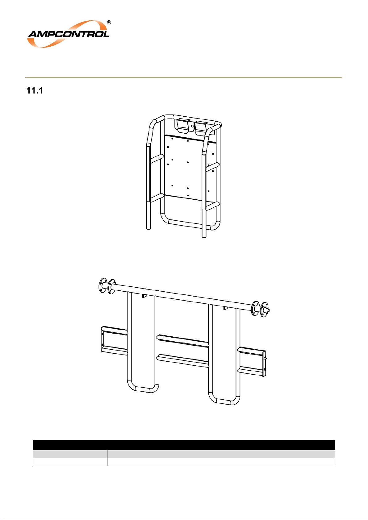
Ampcontrol Pty Ltd – ABN 28 000 915 542
ROCKSTARTER USER MANUAL
MAG-222 Version 2 – MARCH/19
Uncontrolled Copy - Refer to Ampcontrol Website for Latest Version
Page 85 of 127
APPROVED FOR EXTERNAL DISTRIBUTION
– PROPERTY OF AMPCONTROL PTY LTD
– NOT TO BE REPRODUCED IN PART
11 ACCESSORIES & SPARE PARTS
Accessories
Figure 36: Rockstarter Mounting Frame C/W Bolts – PN: 177190
Figure 37: Rockstarter Mounting Bar Kit – PN: 177191
Accessories
Part Number
Description
190491
CLAMP 48mm PIPE SWIVEL COUPLING
Page 86
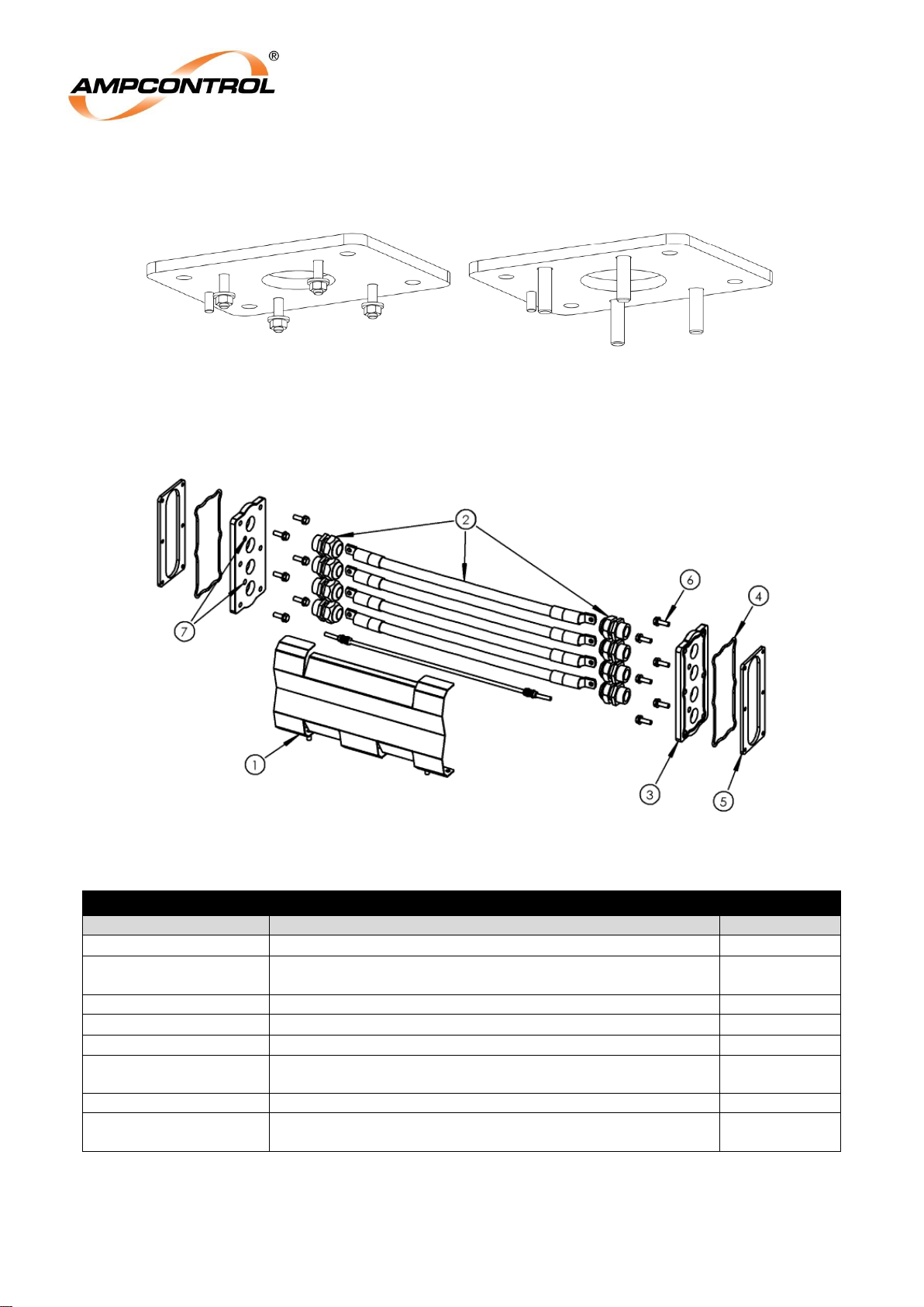
Ampcontrol Pty Ltd – ABN 28 000 915 542
ROCKSTARTER USER MANUAL
MAG-222 Version 2 – MARCH/19
Uncontrolled Copy - Refer to Ampcontrol Website for Latest Version
Page 86 of 127
APPROVED FOR EXTERNAL DISTRIBUTION
– PROPERTY OF AMPCONTROL PTY LTD
– NOT TO BE REPRODUCED IN PART
Figure 38: Rockstarter Adaptor Plates - 60A left (PN: 179292) & 150A right (PN: 181811)
Figure 39: Through Feed Kit – 181441
PN: 181441 - KIT FEED THROUGH COMPLETE WITH GUARD ROCKSTARTER
Part Number
Description
Item Number
181062
COVER FEED THROUGH ROCKSTARTER
1
179168
KIT CABLE FEED THROUGH ROCKSTARTER
Includes all 4 through feed cables, pilot cable, and glands
2
179565
PLATE GLAND THROUGH 4 HOLES ROCKSTARTER
3
179093
O-RING GLAND PLATE THROUGH FEED ROCKSTARTER
4
180269
BACKING PLATE THROUGH ROCKSTARTER
5
181869
KIT SCREW WASHER GLAND FEED THROUGH
ROCKSTARTER
6
181461
PLUG NYLON BLANKING 12mm
7
190882
KIT SCREW WASHER ELECTRICAL FEED THROUGH
ROCKSTARTER (for securing cable lugs)
-
Page 87
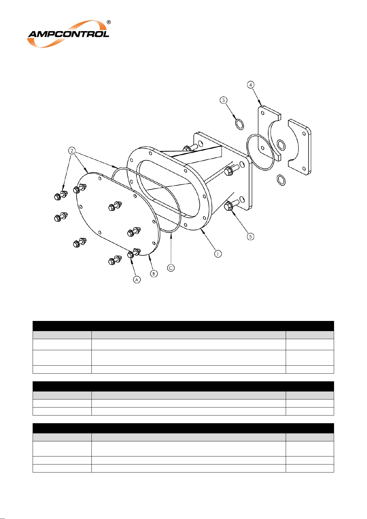
Ampcontrol Pty Ltd – ABN 28 000 915 542
ROCKSTARTER USER MANUAL
MAG-222 Version 2 – MARCH/19
Uncontrolled Copy - Refer to Ampcontrol Website for Latest Version
Page 87 of 127
APPROVED FOR EXTERNAL DISTRIBUTION
– PROPERTY OF AMPCONTROL PTY LTD
– NOT TO BE REPRODUCED IN PART
Figure 40: Dual Gland Junction Box
PN: 181903 - KIT JUNCTION BOX DUAL GLAND ROCKSTARTER
Part Number
Description
Item Number
181905
JUNCTION BOX DUAL GLAND ROCKSTARTER
1
TBC
KIT PLATE GLAND EXTENSION HOUSING ROCKSTARTER
(see kit below)
2
181843
KIT O-RING GLAND PLATE MAIN ENTRY ROCKSTARTER
3
Accessories (Not Included in Kit)
Part Number
Description
Item Number
180576
BACKING PLATE MAIN ENTRY ROCKSTARTER
4
181868
KIT SCREW WASHER MAIN ENTRY ROCKSTARTER
5
PN: TBC - KIT PLATE GLAND EXTENSION HOUSING ROCKSTARTER
Part Number
Description
Item Number
190884
KIT SCREW WASHER GLAND PLATE EXTENSION
ROCKSTARTER
A
181906
PLATE GLAND JUNCTION BOX DUAL GLAND ROCKSTARTER
B
181907
O-RING JUNCTION BOX DUAL GLAND ROCKSTARTER
C
Page 88
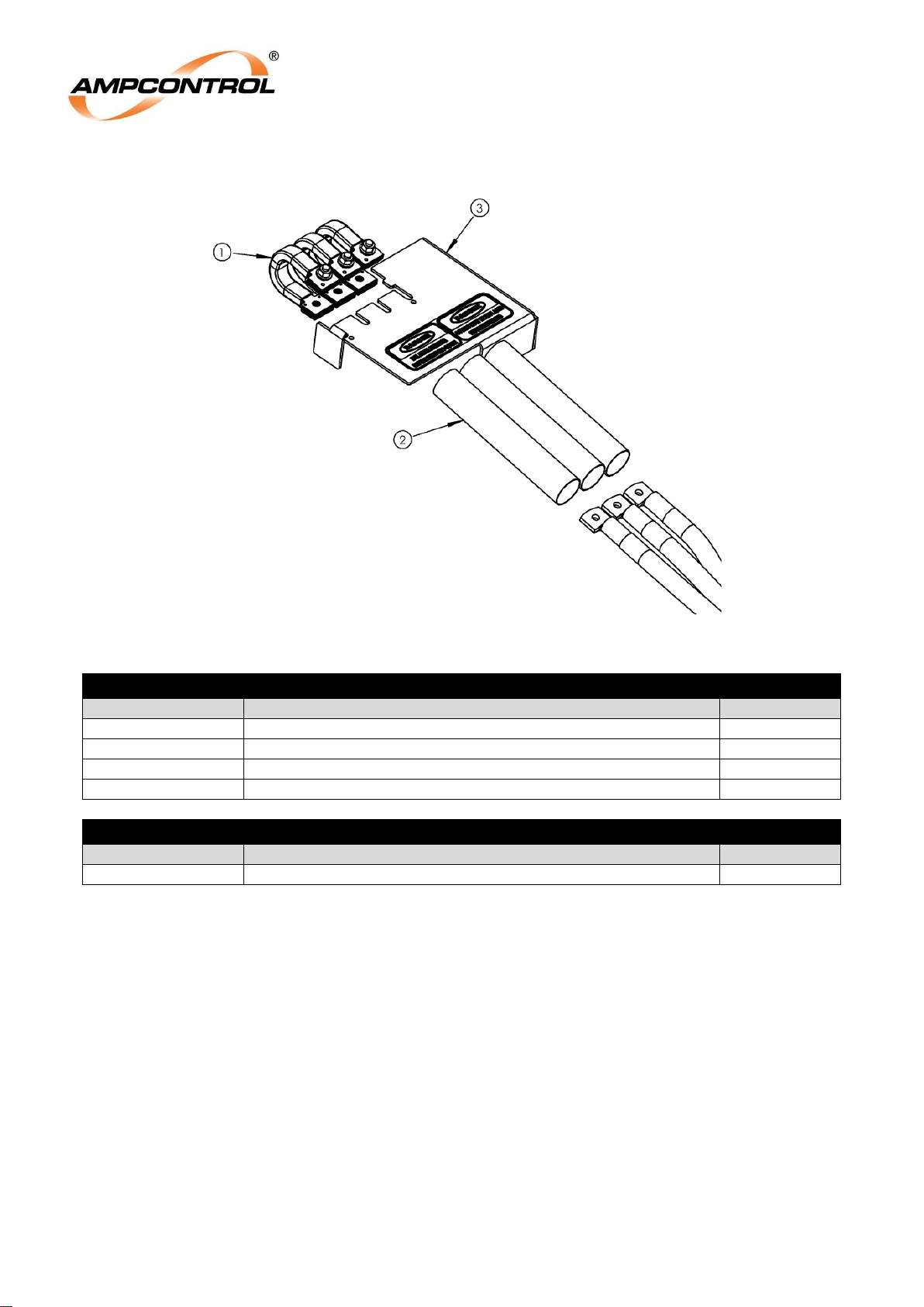
Ampcontrol Pty Ltd – ABN 28 000 915 542
ROCKSTARTER USER MANUAL
MAG-222 Version 2 – MARCH/19
Uncontrolled Copy - Refer to Ampcontrol Website for Latest Version
Page 88 of 127
APPROVED FOR EXTERNAL DISTRIBUTION
– PROPERTY OF AMPCONTROL PTY LTD
– NOT TO BE REPRODUCED IN PART
Figure 41: Dual Incomer Termination
PN: 181881 - KIT TERMINATION DUAL INCOMER ROCKSTARTER
Part Number
Description
Item Number
181904
BUSBAR FLEXIBLE ROCKSTARTER
1
190441
INSULATION TERMINATION DUAL INCOMER ROCKSTARTER
2
190501
COVER PLASTIC LINE CADDY DUAL FEED ROCKSTARTER
3
138972
CABLE TIE NYLON BLACK 300x4.8mm
-
Accessories (Not Included in Kit)
Part Number
Description
Item Number
181872
KIT COVER INTERNAL INCOMER ROCKSTARTER
3
Page 89
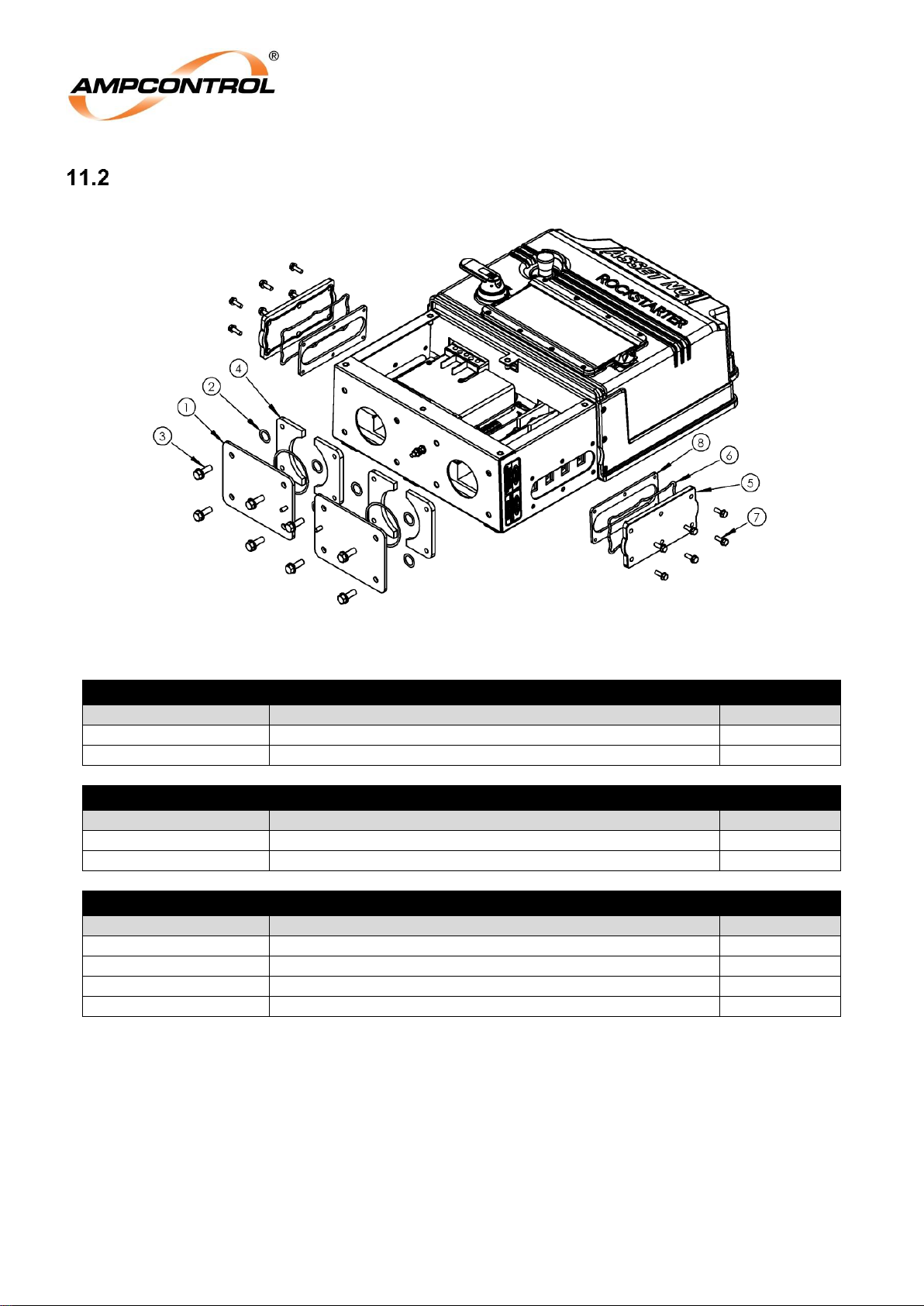
Ampcontrol Pty Ltd – ABN 28 000 915 542
ROCKSTARTER USER MANUAL
MAG-222 Version 2 – MARCH/19
Uncontrolled Copy - Refer to Ampcontrol Website for Latest Version
Page 89 of 127
APPROVED FOR EXTERNAL DISTRIBUTION
– PROPERTY OF AMPCONTROL PTY LTD
– NOT TO BE REPRODUCED IN PART
Spare Parts
Figure 42: Rockstarter Gland Plate & Feed Through Kits
PN: 179169 - KIT GLAND PLATE LINE/LOAD ROCKSTARTER
Part Number
Description
Item Number
179126
PLATE GLAND MAIN ROCKSTARTER
1
181843
KIT O-RING GLAND PLATE MAIN ENTRY ROCKSTARTER
2
Accessories (Not Included in Kit)
Part Number
Description
Item Number
181868
KIT SCREW WASHER MAIN ENTRY ROCKSTARTER
3
180576
BACKING PLATE MAIN ENTRY ROCKSTARTER
4
FEED THROUGH COVER COMPONENTS
Part Number
Description
Item Number
179128
COVER FEED THROUGH ROCKSTARTER
5
179093
O-RING GLAND PLATE THROUGH FEED ROCKSTARTER
6
181869
KIT SCREW WASHER FEED THROUGH ROCKSTARTER
7
180269
BACKING PLATE THROUGH ROCKSTARTER
8
Page 90
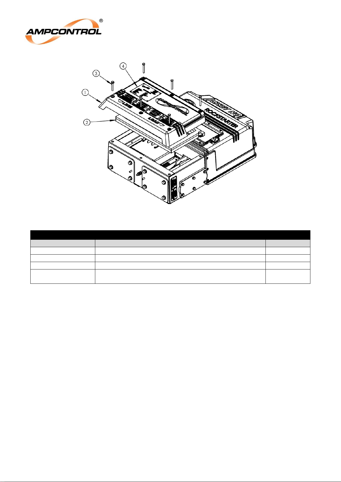
Ampcontrol Pty Ltd – ABN 28 000 915 542
ROCKSTARTER USER MANUAL
MAG-222 Version 2 – MARCH/19
Uncontrolled Copy - Refer to Ampcontrol Website for Latest Version
Page 90 of 127
APPROVED FOR EXTERNAL DISTRIBUTION
– PROPERTY OF AMPCONTROL PTY LTD
– NOT TO BE REPRODUCED IN PART
Figure 43: Rockstarter Terminal Cover Kit
PN: 179171 - KIT COVER TERMINAL CHAMBER ROCKSTARTER
Part Number
Description
Item Number
179094
COVER TERMINAL CHAMBER ROCKSTARTER
1
180513
SEAL TERMINATION COVER ROCKSTARTER
2
181871
KIT SCREW WASHER TERMINAL CHAMBER ROCKSTARTER
3
181870
KIT LABEL MAIN ROCKSTARTER TERMINAL COVER
(Requires Rockstarter serial number to be provided)
4
Page 91
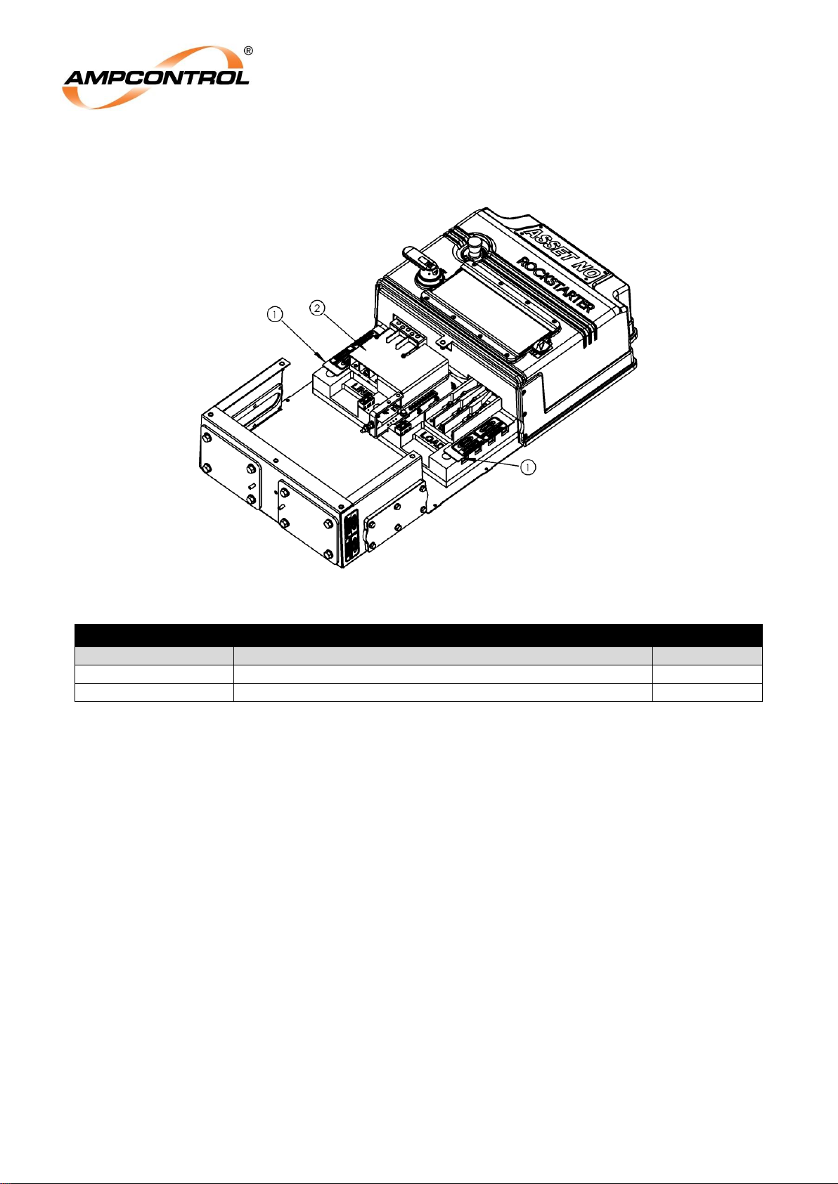
Ampcontrol Pty Ltd – ABN 28 000 915 542
ROCKSTARTER USER MANUAL
MAG-222 Version 2 – MARCH/19
Uncontrolled Copy - Refer to Ampcontrol Website for Latest Version
Page 91 of 127
APPROVED FOR EXTERNAL DISTRIBUTION
– PROPERTY OF AMPCONTROL PTY LTD
– NOT TO BE REPRODUCED IN PART
Figure 44: Rockstarter Secondary Covers
Secondary Covers
Part Number
Description
Item Number
179173
KIT COVER FEED THROUGH INTERNAL ROCKSTARTER
1
181872
KIT COVER INTERNAL INCOMER ROCKSTARTER
2
Page 92
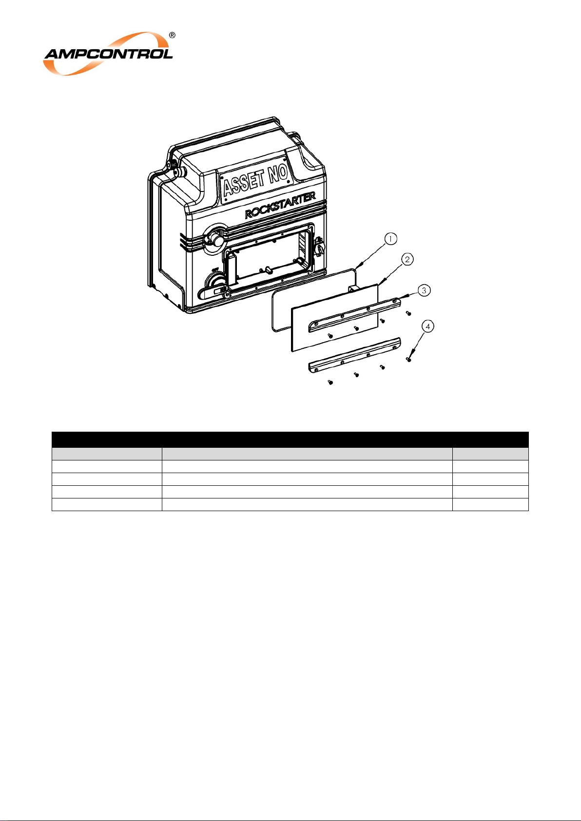
Ampcontrol Pty Ltd – ABN 28 000 915 542
ROCKSTARTER USER MANUAL
MAG-222 Version 2 – MARCH/19
Uncontrolled Copy - Refer to Ampcontrol Website for Latest Version
Page 92 of 127
APPROVED FOR EXTERNAL DISTRIBUTION
– PROPERTY OF AMPCONTROL PTY LTD
– NOT TO BE REPRODUCED IN PART
Figure 45: Rockstarter Capacitive Touch Panel Kit
TOUCH SCREEN GLASS PARTS
Part Number
Description
Item Number
179300
O-RING SCREEN ROCKSTARTER
1
179158
PANEL CAPACITIVE TOUCH ROCKSTARTER
2
179299
FRAME SCREEN ROCKSTARTER
3
130680
SCREEN FRAME Screws SS CSK HD SKT M5x16mm
4
Page 93
Ampcontrol Pty Ltd – ABN 28 000 915 542
ROCKSTARTER USER MANUAL
MAG-222 Version 2 – MARCH/19
Uncontrolled Copy - Refer to Ampcontrol Website for Latest Version
Page 93 of 127
APPROVED FOR EXTERNAL DISTRIBUTION
– PROPERTY OF AMPCONTROL PTY LTD
– NOT TO BE REPRODUCED IN PART
12 SPECIFICATIONS
NOTE
The Rockstarter’s default settings are indicated below with bold font.
Specifications
General
System Voltage
415V / 690V / 1000V
Fault Rating
20kA, 0.5s
Incoming Max Current
250A
Outlet Max Current
250A
Through Supply Max Current
250A
User Interface
7 inch capacitive touchscreen
Rockstarter Asset Name
<16 chars [RKS-001]
Time
Minute [00], Hours [00]
Date
Day [01], Month [01], Year [2000]
Certification
AS/NZS 3000, AS/NZS 2081 and AS/NZS 4871
Mechanical & Environmental
Dimensions (H x W x D)
With Frame: 1161x707x383(mm)
Without Frame: 840x575x230(mm)
Incoming & Outgoing Cable Max
A Lugged maximum of 120mms will fit termination points
Weight – Rockstarter
78kg (excludes receptacle)
Weight – Mounting Frame
35kg
Operating Temperature Range
0°C to +40°C
IP Rating
IP65
Humidity
Between 10% relative humidity and the dew point, non-condensing
UV Stability
None
Segregation
Form 4(b,i,h)
Incoming & Outgoing Entry Points
Glanded or Receptacle access through as AS/NZS1299 – 300A
receptacle footprint opening
Mode of Operation
Outlet Control Mode
Normal, Fan, Pump
System Voltage
415V / 690V / 1000V
Starting Options
Remote Start at Machine
ON / OFF
Restart After Power Cycle
OFF, 0.0, 0.5, 1.0, 1.5, 2.0, 2.5, 3.0, 3.5, 4.0, 4.5, 5.0, 5.5, 6.0, 6.5, 7.0,
7.5, 8.0, 8.5, 9.0, 9.5, 10.0 minutes
Pilot Termination
Diode, LCM
LCM
LCM Asset Name
<16 chars [LCM-001]
RTD 1-2 Trip Level
0-200 [0]
RTD 3-5 Trip Level
0-200 [0]
RTD 1-2 Reset Level
0-200 [0]
RTD 3-5 Reset level
0-200 [0]
Network Parameters
IP Address
nnn.nnn.nnn.nnn format (Where nnn is from
1 to 3 characters and ranges from 0 to 255)
10.1.1.10
Subnet Mask
255.255.255.0
Gateway
1.1.1.1
Page 94
Ampcontrol Pty Ltd – ABN 28 000 915 542
ROCKSTARTER USER MANUAL
MAG-222 Version 2 – MARCH/19
Uncontrolled Copy - Refer to Ampcontrol Website for Latest Version
Page 94 of 127
APPROVED FOR EXTERNAL DISTRIBUTION
– PROPERTY OF AMPCONTROL PTY LTD
– NOT TO BE REPRODUCED IN PART
Pump / Fan Protection Functions
Pump Protection
Sleep Timing Mode
Incremental or Fixed
Snore Current
30, 35, 40 , 45, 50, 55, 60, 65, 70, 75, 80, 85, 90, 95% FLC
Sleep Time
0.5, 1, 2, 3, 4, 5, 10, 15, 20, 30, 60m
Fan Protection
Burp Timing Mode
Incremental or Fixed
Delayed Fan Start
OFF, 0, 1, 2, 3, 4, 5, 10, 15, 20, 25, 30, 45, 60 ,75, 90, 105, 120m
Burp Cycles
0, 1, 2, 3, 4
Burp Cycle ON Time
1, 2, 3, 4, 5, 10, 15, 20s
Burp Cycle OFF Time
1, 2, 3, 4, 5, 10, 15, 20s
Post-blast Start Timer
OFF, 0, 0.5, 1, 2, 3, 4, 5, 10, 15, 20, 30, 60m
Blast Pressure Level
2, 4, 6, 8, 10 kPa
Touch Potential Protection Functions
Earth Leakage
Frequency Response
Weighted Wideband, 5Hz – 10 kHz
Trip Times
Instant, 50, 75, 100, 150, 200, 250, 300, 350, 400, 450, 500ms
Trip Levels
30, 50, 100, 150, 200, 250, 300, 350, 400, 450, 500mA
Earth Continuity
Trip Times
100, 150, 200, 300, 400, 500ms, OFF
Trip Levels – Series
10, 15, 20, 25, 30, 35, 40, 45Ω
Trip Levels – Shunt
1500Ω
Latching Trip
ON / OFF
Frozen Contactor/Loss of Vacuum
Back EMF Timer
2, 5, 10, 15, 20s
Loss of Vacuum Level
OFF, 25, 50, 100, 150VAC
Load Related Protection Functions
Over Load Protection
OL Model
Very Inverse, Extreme Inverse, Motor Overload
Time Multiplier
0.05, 0.055, 0.06, 0.065, 0.07, 0.075, 0.08, 0.085, 0.09, 0.1, 0.11, 0.12,
0.13, 0.14, 0.15, 0.16, 0.17, 0.18, 0.19, 0.2, 0.22, 0.24, 0.26, 0.28, 0.3,
0.32, 0.35, 0.38, 0.42, 0.46, 0.5, 0.55, 0.6, 0.65, 0.7, 0.75, 0.8, 0.85,
0.9, 1, 1.1, 1.2, 1.3, 1.4, 1.5, 1.6, 1.7 ,1.8, 1.9, 2, 2.2, 2.4, 2.6, 2.8, 3,
3.2, 3.5, 3.8, 4.2, 4.6, 5, 5.5, 6, 6.5, 7, 7.5, 8, 8.5, 9, 10, 11, 12, 13, 14,
15, 16, 17, 18, 19, 20, 22, 24, 26, 28, 30x FLC
FLC
2-250A [10A]
Cooling Multiplier
1.0x, 1.5x, 2.0x, 2.5x, 3.0x, 4.0x, 5.0x
Thermal Accumulator Start Block
20, 30, 40, 50, 60, 70, 80, 90%
Short Circuit Protection
Current Multiplier (trip level)
1.5x, 1.75x, 2x, 2.25x, 2.5x, 2.75x, 3x, 3.25x, 3.5x, 3.75x, 4x, 4.25x,
4.5x, 4.75x, 5x, 5.25x, 5.5x, 5.75x, 6x, 6.25x, 6.5x, 6.75x, 7x, 7.25x,
7.5x, 7.75x, 8x, 8.25x, 8.5x, 8.75x, 9x, 9.25x, 9.5x, 9.75x, 10x, 10.25x,
10.5x, 10.75x, 11x, 11.25x, 11.5x, 11.75x, 12x, 12.25x, 12.5x FLC
Time
40 ,60, 80, 100, 120, 140, 160, 180, 200ms
Under Voltage Protection
Trip Level
OFF, 40, 50, 60, 70, 75, 80, 85, 90, 95%
Current Balance Protection
Trip Level
OFF, 5, 10, 20, 50% FLC
Under Current Protection
Trip Level
OFF, 30, 35, 40 , 45, 50, 55, 60 , 65, 70, 75, 80, 85, 90, 95% FLC
Find Out More
For more information on this product, contact Ampcontrol Customer Service on +61 1300 267 373 or
[email protected] or visit the Ampcontrol website: www.ampcontrolgroup.com
Page 95
Ampcontrol Pty Ltd – ABN 28 000 915 542
ROCKSTARTER USER MANUAL
MAG-222 Version 2 – MARCH/19
Uncontrolled Copy - Refer to Ampcontrol Website for Latest Version
Page 95 of 127
APPROVED FOR EXTERNAL DISTRIBUTION
– PROPERTY OF AMPCONTROL PTY LTD
– NOT TO BE REPRODUCED IN PART
13 EQUIPMENT LIST
Rockstarter & Accessories
Rockstarter
Part Number
Description
177193
Rockstarter 1000V 250A Motor Starter
Accessories – Mechanical
Mounting
Part Number
Description
177190
KIT FRAME MOUNTING COMPLETE WITH FASTENERS
ROCKSTARTER
177191
KIT BAR MOUNTING 2UNIT COMPLETE WITH 2x CLAMPS
ROCKSTARTER
180858
ASSEMBLY BRACKET LIFTING ROCKSTARTER
Line/Load Connections
Part Number
Description
177187
KIT RECEPTACLE ROCKSTARTER – QUOTED PER ORDER
179292
PLATE ADAPTOR RECEPTACLE 60A ROCKSTARTER
181811
PLATE ADAPTOR RECEPTACLE 150A ROCKSTARTER
181903
KIT JUNCTION BOX DUAL GLAND ROCKSTARTER
Through Feed
Part Number
Description
181441
KIT FEED THROUGH COMPLETE WITH GUARD ROCKSTARTER
General
Part Number
Description
181484
LABEL ASSET NUMBER ROCKSTARTER
Accessories – Electrical
General
Part Number
Description
177194
KEY RADIO FREQUENCY IDENTIFICATION ROCKSTARTER
(requires programming sheet on order)
181876
CABLE FAN SEQUENCING ROCKSTARTER
115119
PTB PILOT TERMINATION
181881
KIT TERMINATION DUAL INCOMER ROCKSTARTER
Load Connection Module
Part Number
Description
180485
LOAD CONTROL MODULE ROCKSTARTER COMPLETE WITH DONGLE
172093
DONGLE PARAMETER LCM
Auxiliary I/O Connector
Part Number
Description
179179
JUNCTION BOX INPUT/OUTPUT ROCKSTARTER
179180
CABLE INPUT/OUTPUT 1m ROCKSTARTER
179181
CABLE INPUT/OUTPUT 2m ROCKSTARTER
179182
CABLE INPUT/OUTPUT 5m ROCKSTARTER
Outlet Testing System
Part Number
Description
176852
Tablet 8” LTE complete with OTS software and case
177451
Tablet non LTE complete with OTS software and case
Page 96
Ampcontrol Pty Ltd – ABN 28 000 915 542
ROCKSTARTER USER MANUAL
MAG-222 Version 2 – MARCH/19
Uncontrolled Copy - Refer to Ampcontrol Website for Latest Version
Page 96 of 127
APPROVED FOR EXTERNAL DISTRIBUTION
– PROPERTY OF AMPCONTROL PTY LTD
– NOT TO BE REPRODUCED IN PART
Rockstarter Spares
Spare Parts – Mechanical
Line/Load Gland Plate
Part Number
Description
179169
KIT GLAND PLATE LINE/LOAD ROCKSTARTER
179126
PLATE GLAND MAIN ROCKSTARTER
181843
KIT O-RING GLAND PLATE MAIN ENTRY ROCKSTARTER
180576
BACKING PLATE MAIN ENTRY ROCKSTARTER
181868
KIT SCREW WASHER MAIN ENTRY ROCKSTARTER
Through Feed / Through Feed Gland Plate
Part Number
Description
181062
GUARD THROUGH FEED ROCKSTARTER
179168
KIT CABLE FEED THROUGH ROCKSTARTER
Includes all 4 through feed cables, pilot cable, and glands
179565
PLATE GLAND THROUGH 4 HOLES ROCKSTARTER
179093
O-RING GLAND PLATE THROUGH FEED ROCKSTARTER
180269
BACKING PLATE THROUGH ROCKSTARTER
181869
KIT SCREW WASHER GLAND FEED THROUGH ROCKSTARTER
181461
PLUG NYLON BLANKING 12mm
190882
KIT SCREW WASHER ELECTRICAL FEED THROUGH ROCKSTARTER
Terminal Cover
Part Number
Description
179171
KIT COVER TERMINAL CHAMBER ROCKSTARTER
179094
COVER TERMINAL CHAMBER ROCKSTARTER
180513
SEAL TERMINATION COVER ROCKSTARTER
181870
KIT LABEL MAIN ROCKSTARTER TERMINAL COVER
(Requires Rockstarter serial number to be provided)
181871
KIT SCREW WASHER TERMINAL CHAMBER ROCKSTARTER
Dual Gland Junction Box
Part Number
Description
181905
JUNCTION BOX DUAL GLAND ROCKSTARTER
181906
PLATE GLAND JUNCTION BOX DUAL GLAND ROCKSTARTER
181907
O-RING JUNCTION BOX DUAL GLAND ROCKSTARTER
190884
KIT SCREW WASHER GLAND PLATE EXTENSIONROCKSTARTER
Secondary Internal Covers
Part Number
Description
179173
KIT COVER FEED THROUGH INTERNAL ROCKSTARTER
181872
KIT COVER INTERNAL INCOMER ROCKSTARTER
179091
COVER PLASTIC LINE CADDY ROCKSTARTER
190501
COVER PLASTIC LINE CADDY DUAL FEED ROCKSTARTER
General
Part Number
Description
190491
CLAMP 48mm PIPE SWIVEL COUPLING
Page 97
Ampcontrol Pty Ltd – ABN 28 000 915 542
ROCKSTARTER USER MANUAL
MAG-222 Version 2 – MARCH/19
Uncontrolled Copy - Refer to Ampcontrol Website for Latest Version
Page 97 of 127
APPROVED FOR EXTERNAL DISTRIBUTION
– PROPERTY OF AMPCONTROL PTY LTD
– NOT TO BE REPRODUCED IN PART
Spare Parts – Electrical
User Interface
Part Number
Description
179300
O-RING SCREEN ROCKSTARTER
179158
PANEL CAPACITIVE TOUCH ROCKSTARTER
179299
FRAME SCREEN ROCKSTARTER
130680
SCREEN FRAME Screws SS CSK HD SKT M5x16mm
Incomer / Outgoing Termination
Part Number
Description
101086
NUT HEX SS304 M8
180132
WASHER BELLEVILLE HD GALV M8
Through Feed
Part Number
Description
179168
KIT CABLE FEED THROUGH ROCKSTARTER
190882
KIT SCREW WASHER ELECTRICAL FEED THROUGH ROCKSTARTER
Dual Incomer Termination
Part Number
Description
181904
BUSBAR FLEXIBLE ROCKSTARTER
190441
INSULATION TERMINATION DUAL INCOMER ROCKSTARTER
General
Part Number
Description
179449
CAP DUST RJ45 BULKHEAD
181438
CAP DUST BULGIN 6012 SERIES
181878
KIT FUSE 10x 4A 1.2kV SB HRC-15kA
190558
KIT FUSE 10x 3.15A 250V SB HRC
Page 98
Ampcontrol Pty Ltd – ABN 28 000 915 542
ROCKSTARTER USER MANUAL
MAG-222 Version 2 – MARCH/19
Uncontrolled Copy - Refer to Ampcontrol Website for Latest Version
Page 98 of 127
APPROVED FOR EXTERNAL DISTRIBUTION
– PROPERTY OF AMPCONTROL PTY LTD
– NOT TO BE REPRODUCED IN PART
APPENDIX A: PROTECTION ELEMENT LOAD CURRENT TABLES
A1: Protection Module Full Load Current Table
Protection Module Full Load Current Selection Table – Amps (1000:1 CT), and Max effective
SC Level
Value
Amps
Value
Amps
Value
Amps
Value
Amps
Value
Amps
Value
Amps
SC max
Value
Amps
SC max
0
2.00
32
4.00
64
8.0
96
16.0
128
32.0
160
64.0
25.0x
192
128
18.4x
1
2.05
33
4.10
65
8.2
97
16.4
129
32.8
161
65.6
25.0x
193
131
17.9x
2
2.10
34
4.20
66
8.4
98
16.8
130
33.6
162
67.1
25.0x
194
134
17.5x
3
2.15
35
4.29
67
8.6
99
17.2
131
34.3
163
68.7
25.0x
195
137
17.2x
4
2.20
36
4.39
68
8.8
100
17.6
132
35.1
164
70.2
25.0x
196
140
16.8x
5
2.24
37
4.49
69
9.0
101
18.0
133
35.9
165
71.8
25.0x
197
144
16.3x
6
2.29
38
4.59
70
9.2
102
18.3
134
36.7
166
73.4
25.0x
198
147
16.0x
7
2.34
39
4.68
71
9.4
103
18.7
135
37.5
167
74.9
25.0x
199
150
15.7x
8
2.39
40
4.78
72
9.6
104
19.1
136
38.2
168
76.5
25.0x
200
153
15.4x
9
2.44
41
4.88
73
9.8
105
19.5
137
39.0
169
78.0
25.0x
201
156
15.1x
10
2.49
42
4.98
74
10.0
106
19.9
138
39.8
170
79.6
25.0x
202
159
14.8x
11
2.54
43
5.07
75
10.1
107
20.3
139
40.6
171
81.2
25.0x
203
162
14.5x
12
2.59
44
5.17
76
10.3
108
20.7
140
41.4
172
82.7
25.0x
204
165
14.2x
13
2.63
45
5.27
77
10.5
109
21.1
141
42.1
173
84.3
25.0x
205
169
13.9x
14
2.68
46
5.37
78
10.7
110
21.5
142
42.9
174
85.9
25.0x
206
172
13.7x
15
2.73
47
5.46
79
10.9
111
21.9
143
43.7
175
87.4
25.0x
207
175
13.4x
16
2.78
48
5.56
80
11.1
112
22.2
144
44.5
176
89.0
25.0x
208
178
13.2x
17
2.83
49
5.66
81
11.3
113
22.6
145
45.3
177
90.5
25.0x
209
181
13.0x
18
2.88
50
5.76
82
11.5
114
23.0
146
46.0
178
92.1
25.0x
210
184
12.8x
19
2.93
51
5.85
83
11.7
115
23.4
147
46.8
179
93.7
25.0x
211
187
12.6x
20
2.98
52
5.95
84
11.9
116
23.8
148
47.6
180
95.2
24.7x
212
190
12.4x
21
3.02
53
6.05
85
12.1
117
24.2
149
48.4
181
96.8
24.3x
213
194
12.1x
22
3.07
54
6.15
86
12.3
118
24.6
150
49.2
182
98.3
23.9x
214
197
11.9x
23
3.12
55
6.24
87
12.5
119
25.0
151
50.0
183
100
23.5x
215
200
11.8x
24
3.22
56
6.44
88
12.9
120
25.8
152
51.5
184
103
22.8x
216
206
11.4x
Page 99
Ampcontrol Pty Ltd – ABN 28 000 915 542
ROCKSTARTER USER MANUAL
MAG-222 Version 2 – MARCH/19
Uncontrolled Copy - Refer to Ampcontrol Website for Latest Version
Page 99 of 127
APPROVED FOR EXTERNAL DISTRIBUTION
– PROPERTY OF AMPCONTROL PTY LTD
– NOT TO BE REPRODUCED IN PART
Protection Module Full Load Current Selection Table – Amps (1000:1 CT), and Max effective
SC Level
Value
Amps
Value
Amps
Value
Amps
Value
Amps
Value
Amps
Value
Amps
SC max
Value
Amps
SC max
25
3.32
57
6.63
89
13.3
121
26.5
153
53.1
185
106
22.2x
217
212
11.1x
26
3.41
58
6.83
90
13.7
122
27.3
154
54.6
186
109
21.6x
218
219
10.7x
27
3.51
59
7.02
91
14.0
123
28.1
155
56.2
187
112
21.0x
219
225
10.4x
28
3.61
60
7.22
92
14.4
124
28.9
156
57.8
188
116
20.3x
220
231
10.2x
29
3.71
61
7.41
93
14.8
125
29.7
157
59.3
189
119
19.7x
221
237
9.9x
30
3.80
62
7.61
94
15.2
126
30.4
158
60.9
190
122
19.3x
222
244
9.6x
31
3.90
63
7.80
95
15.6
127
31.2
159
62.4
191
125
18.8x
223
250
9.4x
Page 100
Ampcontrol Pty Ltd – ABN 28 000 915 542
ROCKSTARTER USER MANUAL
MAG-222 Version 2 – MARCH/19
Uncontrolled Copy - Refer to Ampcontrol Website for Latest Version
Page 100 of
127
APPROVED FOR EXTERNAL DISTRIBUTION
– PROPERTY OF AMPCONTROL PTY LTD
– NOT TO BE REPRODUCED IN PART
A2: Protection Module TMS Table
Protection Module Over Current Time Multiplier Settings (TMS) including nominal trip time in
seconds at 10 PU Current
Value
TMS
10 x trip time
Value
TMS
10 x trip time
Value
TMS
10 x trip time
Ext Inv.
& MOL
Very
Inv.
Ext Inv.
& MOL
Very
Inv.
Ext Inv.
& MOL
Very
Inv.
0
0.050
0.040
0.075
30
0.50
0.404
0.750
60
5.0
4.04
7.50
1
0.055
0.044
0.083
31
0.55
0.444
0.825
61
5.5
4.44
8.25
2
0.060
0.048
0.090
32
0.60
0.485
0.900
62
6.0
4.85
9.00
3
0.065
0.053
0.098
33
0.65
0.525
0.975
63
6.5
5.25
9.75
4
0.070
0.057
0.105
34
0.70
0.566
1.050
64
7.0
5.66
10.50
5
0.075
0.061
0.113
35
0.75
0.606
1.125
65
7.5
6.06
11.25
6
0.080
0.065
0.120
36
0.80
0.646
1.200
66
8.0
6.46
12.00
7
0.085
0.069
0.128
37
0.85
0.687
1.275
67
8.5
6.87
12.75
8
0.090
0.073
0.135
38
0.90
0.727
1.350
68
9.0
7.27
13.50
9
0.10
0.081
0.150
39
1.0
0.808
1.50
69
10.0
8.08
15.0
10
0.11
0.089
0.165
40
1.1
0.889
1.65
70
11.0
8.89
16.5
11
0.12
0.097
0.180
41
1.2
0.970
1.80
71
12.0
9.70
18.0
12
0.13
0.105
0.195
42
1.3
1.05
1.95
72
13.0
10.51
19.5
13
0.14
0.113
0.210
43
1.4
1.13
2.10
73
14.0
11.31
21.0
14
0.15
0.121
0.225
44
1.5
1.21
2.25
74
15.0
12.12
22.5
15
0.16
0.129
0.240
45
1.6
1.29
2.40
75
16.0
12.93
24.0
16
0.17
0.137
0.255
46
1.7
1.37
2.55
76
17.0
13.74
25.5
17
0.18
0.145
0.270
47
1.8
1.45
2.70
77
18.0
14.55
27.0
18
0.19
0.154
0.285
48
1.9
1.54
2.85
78
19.0
15.35
28.5
19
0.20
0.162
0.300
49
2.0
1.62
3.00
79
20.0
16.16
30.0
20
0.22
0.178
0.330
50
2.2
1.78
3.30
80
22.0
17.78
33.0
21
0.24
0.194
0.360
51
2.4
1.94
3.60
81
24.0
19.39
36.0
22
0.26
0.210
0.390
52
2.6
2.10
3.90
82
26.0
21.01
39.0
23
0.28
0.226
0.420
53
2.8
2.26
4.20
83
28.0
22.63
42.0
 Loading...