

Page 1
Version: 5, November 2020
Designed and manufactured in Australia by Ampcontrol Pty Ltd
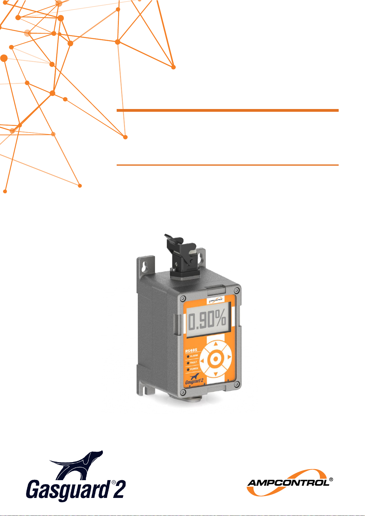
GG2 DISPLAY
4-20mA / IMAC / RS485
User Manual
Page 2
Ampcontrol Pty Ltd – ABN 28 000 915 542
GG2 DISPLAY USER MANUAL
GG2B023
Version 5 – NOVEMBER/2020
Uncontrolled Copy - Refer to Ampcontrol Website for Latest Version
Page 2 of 62
APPROVED FOR EXTERNAL DISTRIBUTION
– PROPERTY OF AMPCONTROL PTY LTD
– NOT TO BE REPRODUCED IN PART
WARNING!
The warning symbol highlights a potential risk malfunction or loss of
performance
Please share these warnings with other operators.
CAUTION!
The caution symbol highlights a potential risk of damage to
equipment.
Please share these cautions with other operators.
NOTE
The note symbol highlights key information.
Please share these notes with other operators.
ENVIRO
The enviro (environmental) symbol highlights areas which may have an
impact on the surrounding fauna and/or flora.
Page 3
Ampcontrol Pty Ltd – ABN 28 000 915 542
GG2 DISPLAY USER MANUAL
GG2B023
Version 5 – NOVEMBER/2020
Uncontrolled Copy - Refer to Ampcontrol Website for Latest Version
Page 3 of 62
APPROVED FOR EXTERNAL DISTRIBUTION
– PROPERTY OF AMPCONTROL PTY LTD
– NOT TO BE REPRODUCED IN PART
Copyright Notice
The Ampcontrol GG2 Real Time Gas Monitoring System described in this document is the property of
AMPCONTROL PTY LTD. It is furnished under a license agreement and is to be used only in
accordance with the terms of the agreement.
No part of the hardware or documentation may be reproduced, transmitted, transcribed, stored in any
retrieval system, or translated into any language or computer language, in any form or by any means,
without prior written permission of AMPCONTROL PTY LTD.
Disclaimer
While every effort has been made to assure the accuracy and clarity of this document, AMPCONTROL
PTY LTD assumes no liability resulting from any omissions in this document, or from misuse of the
information obtained herein. The information in this document has been carefully checked and is believed
to be entirely reliable with all of the necessary information included. AMPCONTROL PTY LTD reserves
the right to make changes to any products described herein to improve reliability, function, or design, and
reserves the right to revise this document and make changes from time to time in content hereof with no
obligation to notify any persons of revisions or changes. AMPCONTROL PTY LTD does not assume any
liability arising out of the application or any use of any product or circuit described herein; neither does it
convey license under its patent rights or the rights of others.
Before You Begin
Thank you for purchasing from the Ampcontrol GG2 range.
WARNING!
In the interests of safety and correct equipment operation, please
take the time to read and understand the content in this manual.
Ampcontrol Contact Details
7 Billbrooke Close, Cameron Park, NSW, 2285
P +61 1300 267 373 | F +61 2 4903 4888
EMAIL: [email protected]
WEB: ampcontrolgroup.com
Page 4

Ampcontrol Pty Ltd – ABN 28 000 915 542
GG2 DISPLAY USER MANUAL
GG2B023
Version 5 – NOVEMBER/2020
Uncontrolled Copy - Refer to Ampcontrol Website for Latest Version
Page 4 of 62
APPROVED FOR EXTERNAL DISTRIBUTION
– PROPERTY OF AMPCONTROL PTY LTD
– NOT TO BE REPRODUCED IN PART
TABLE OF CONTENTS
DEFINITIONS ...................................................................................................... 9
1 SAFETY AND OTHER WARNINGS ................................................................ 11
1.1 Safe Use of Equipment ............................................................................ 11
1.2 Supplementary Documentation ................................................................ 11
2 RECEIVING AND STORAGE .......................................................................... 12
2.1 Receiving ................................................................................................. 12
2.2 Inspection ................................................................................................ 12
2.3 Storage after Delivery .............................................................................. 12
2.4 Unpacking of Equipment .......................................................................... 12
3 PRODUCT OVERVIEW .................................................................................. 13
3.1 Overview .................................................................................................. 13
3.2 Key Features ........................................................................................... 13
3.3 Markings .................................................................................................. 15
3.4 Enclosure ................................................................................................. 16
3.5 Certification .............................................................................................. 16
4 INSTALLATION ............................................................................................... 17
4.1 General Warnings .................................................................................... 17
4.2 Mandatory Installation Practices .............................................................. 18
4.3 Conditions of Safe Use ............................................................................ 18
4.4 Mechanical Installation Information .......................................................... 19
4.5 Electrical Installation Information ............................................................. 23
5 PRODUCT OPERATION ................................................................................. 28
5.1 Human-Machine Interface ........................................................................ 28
5.2 System States.......................................................................................... 34
5.3 Connecting and Disconnecting a GG2 Detector ....................................... 35
5.4 External Interfaces ................................................................................... 39
5.5 Gas Alarm and Setpoint Configuration ..................................................... 42
5.6 System Status and Information ................................................................ 45
5.7 Display Maintenance................................................................................ 48
6 SERVICE, MAINTENANCE & DISPOSAL ....................................................... 51
6.1 Equipment Service ................................................................................... 51
6.2 Equipment Maintenance .......................................................................... 52
6.3 Disposal ................................................................................................... 54
7 SPECIFICATIONS .......................................................................................... 55
7.1 GG2 Display ............................................................................................ 55
8 EQUIPMENT LIST .......................................................................................... 56
Page 5

Ampcontrol Pty Ltd – ABN 28 000 915 542
GG2 DISPLAY USER MANUAL
GG2B023
Version 5 – NOVEMBER/2020
Uncontrolled Copy - Refer to Ampcontrol Website for Latest Version
Page 5 of 62
APPROVED FOR EXTERNAL DISTRIBUTION
– PROPERTY OF AMPCONTROL PTY LTD
– NOT TO BE REPRODUCED IN PART
9 APPROVALS .................................................................................................. 57
9.1 IECEx ITA 07.0017X Issue No. 2 ............................................................. 57
9.2 IECEx ExTC 18.0003X Issue No. 0 .......................................................... 57
Page 6

Ampcontrol Pty Ltd – ABN 28 000 915 542
GG2 DISPLAY USER MANUAL
GG2B023
Version 5 – NOVEMBER/2020
Uncontrolled Copy - Refer to Ampcontrol Website for Latest Version
Page 6 of 62
APPROVED FOR EXTERNAL DISTRIBUTION
– PROPERTY OF AMPCONTROL PTY LTD
– NOT TO BE REPRODUCED IN PART
TABLE OF FIGURES
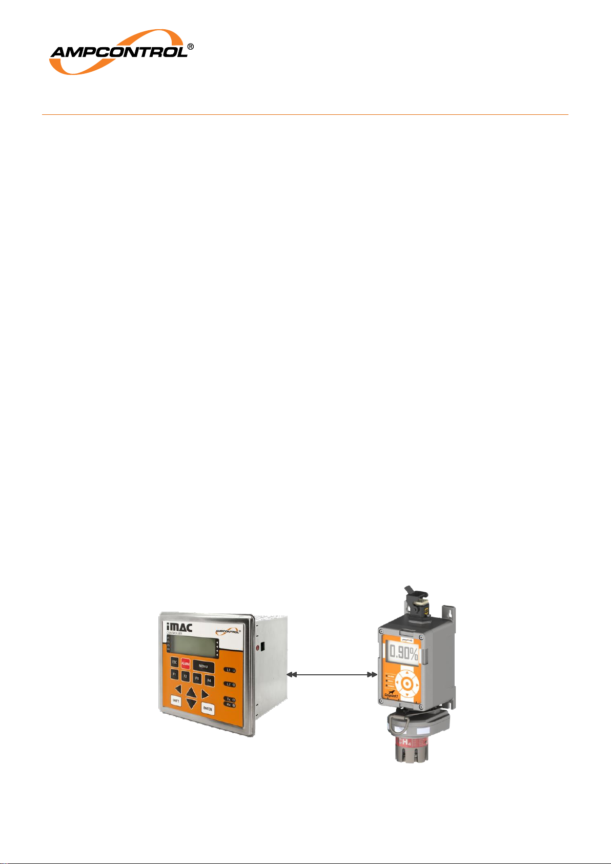
Figure 1: GG2 Example System (iMAC Communication) ........................................................................ 13
Figure 2: GG2 Display Overview ............................................................................................................ 14
Figure 3: GG2 Display Block Diagram .................................................................................................... 14
Figure 4: Glanded GG2 Display .............................................................................................................. 15
Figure 5: GG2 Display Marking .............................................................................................................. 15
Figure 6: GG2 Display Dimensions (mm) ............................................................................................... 20
Figure 7: Glanded GG2 Display Dimensions (mm) ................................................................................. 20
Figure 8: GG2 Display and CH4 Detector Dimensions (mm) .................................................................. 21
Figure 9: GG2 Remote Cable Assembly Dimensions (mm) ................................................................ .... 21
Figure 10: Connecting/Disconnection Detector ....................................................................................... 22
Figure 11: GG2 Display System (S1) Connector (Top) Pin Out .............................................................. 24
Figure 12: GG2 Display Sensor (S2) Connector (Bottom) Pin Out .......................................................... 25
Figure 13: Electrical Connections - Display Enclosure with System Connector....................................... 26
Figure 14: Electrical Connections - Display Enclosure with Glanded Connector ..................................... 27
Figure 15: GG2 Display UI Home Screen Example ................................................................................ 28
Figure 16: Keypad Overview .................................................................................................................. 29
Figure 17: Keypad Guide ........................................................................................................................ 29
Figure 18: Using the Magnetic Wand ...................................................................................................... 30
Figure 19: Menu Level 1 (Configuration Option Selected) ...................................................................... 30
Figure 20: Menu Authorisation ................................................................................................................ 32
Figure 21: Setpoints Configuration Screen ............................................................................................. 32
Figure 22: Numerical field edit mode ...................................................................................................... 33
Figure 23: Save Screen .......................................................................................................................... 33
Figure 24 - Discarding Changes Screen ................................................................................................. 33
Figure 25 - Response test target value editor ......................................................................................... 33
Figure 26: Title Screen (left) & Establishing GG2 Detector Communications (right) ................................ 34
Figure 27 - Initialisation Screen .............................................................................................................. 34
Figure 28 - The Home Screen when in warmup ...................................................................................... 35
Figure 29: Display Sleep Mode ............................................................................................................... 35
Figure 30: Connecting a Detector for the first time .................................................................................. 36
Figure 31: Different Gas Sensor Warning ............................................................................................... 36
Figure 32: Erasing the Old Detector Image ............................................................................................. 37
Figure 33: Updating the Detector Image ................................................................................................. 37
Figure 34: Isolate Detector ..................................................................................................................... 38
Figure 35: Isolate Detector Confirmation ................................................................................................ 38
Figure 36: Detector Isolated ................................................................................................................... 38
Figure 37: Calibration Notice (left) & 4mA Calibration (right) ................................................................... 42
Figure 38: Example Setpoint Configuration ............................................................................................ 43
Figure 39: Configuration - Setpoints ....................................................................................................... 43
Figure 40: Multiple Triggering Scenario .................................................................................................. 44
Figure 41: Using Hysteresis Setting ........................................................................................................ 44
Figure 42: Hysteresis Value for each of the Setpoints ............................................................................ 45
Figure 43: The HOME Screen with a Status Title "FAST PRESSURE CHANGE" .................................. 45
Page 7

Ampcontrol Pty Ltd – ABN 28 000 915 542
GG2 DISPLAY USER MANUAL
GG2B023
Version 5 – NOVEMBER/2020
Uncontrolled Copy - Refer to Ampcontrol Website for Latest Version
Page 7 of 62
APPROVED FOR EXTERNAL DISTRIBUTION
– PROPERTY OF AMPCONTROL PTY LTD
– NOT TO BE REPRODUCED IN PART
Figure 44: The Status Screen - Low Cell Sensitivity ............................................................................... 46
Figure 45: Detector Log Example ........................................................................................................... 47
Figure 46: Display Log Example ............................................................................................................. 47
Figure 47: Reset Last Peak Values Screen ............................................................................................ 48
Figure 48: Reset to Factory Defaults ...................................................................................................... 48
Figure 49: Reverting to Factory Defaults ................................................................................................ 49
Figure 50: Catalytic latch reset ............................................................................................................... 49
Page 8

Ampcontrol Pty Ltd – ABN 28 000 915 542
GG2 DISPLAY USER MANUAL
GG2B023
Version 5 – NOVEMBER/2020
Uncontrolled Copy - Refer to Ampcontrol Website for Latest Version
Page 8 of 62
APPROVED FOR EXTERNAL DISTRIBUTION
– PROPERTY OF AMPCONTROL PTY LTD
– NOT TO BE REPRODUCED IN PART
TABLE OF TABLES
Table 1: Minimum Marking Information ................................................................................................... 16
Table 2: Optional Marking Information .................................................................................................... 18
Table 3: Remote Cable Connections ................................................................ ...................................... 23
Table 4: GG2 Display System (S1) Connector Pin Out ........................................................................... 24
Table 5: GG2 Display Sensor (S2) Connector Pin Out ........................................................................... 25
Table 6: Example of Permyriad to Gas Concentration Conversion ......................................................... 39
Table 7: Modbus - Protocol Configuration - Settings ............................................................................... 40
Table 8: iMAC - Protocol Configuration - Addresses ............................................................................... 40
Table 9: iMAC - Protocol Configuration - General ................................................................................... 41
Table 10: 4-20mA Settings ..................................................................................................................... 41
Table 11: Setpoint Configuration ............................................................................................................ 43
Table 12: System Info Data Fields .......................................................................................................... 46
Table 13: AS/NZS2290.3.2018 - Schedule of Inspection and Tests ........................................................ 53
Table 14: Corrective Maintenance Checks ............................................................................................. 54
Page 9
Ampcontrol Pty Ltd – ABN 28 000 915 542
GG2 DISPLAY USER MANUAL
GG2B023
Version 5 – NOVEMBER/2020
Uncontrolled Copy - Refer to Ampcontrol Website for Latest Version
Page 9 of 62
APPROVED FOR EXTERNAL DISTRIBUTION
– PROPERTY OF AMPCONTROL PTY LTD
– NOT TO BE REPRODUCED IN PART
DEFINITIONS
Term
Definition
CO
2
Carbon Dioxide
CH4
Methane
CO
Carbon Monoxide
O2
Oxygen
H2S
Hydrogen Sulphide
NATA
National Association of Testing Authorities, Australia
NDIR
Non-Dispersive Infrared
Warm Up Time
Time interval, with the equipment in a stated atmosphere, between the time
when the equipment is switched on and the time when the indication reaches
and remains within the stated tolerances
AS/NZS 4641:2007
Electrical apparatus for detection of oxygen and other gases and vapours at
toxic levels - general requirements and test methods
AS/NZS 2290.32018
Electrical equipment for coal mines- maintenance and overhaul Part 3:
maintenance of gas detecting and monitoring equipment.
AS/NZS 2290.31990
Electrical equipment for coal mines - maintenance and overhaul Part 3:
maintenance of gas detecting and monitoring equipment.
AS/NZS 60079-
29.1:2008
Explosive atmospheres part 29.1: Gas detectors - Performance requirements of
detectors for flammable gases
AS/NZS 60079.02011
Explosive atmospheres - Part 0: Equipment - General requirements
AS/NZS 60079.112011
Explosive atmospheres - Part 11: Equipment protection by intrinsic safety "i"
GG2
Gasguard 2
Time of response
T90
Time interval, with the equipment in a warmed-up condition, between the time
when an instantaneous change between clean air and the standard test gas, or
vice versa, is produced at the equipment inlet, and the time when the response
reaches a stated percentage (90%) of the stabilised signal on the standard test
gas
RTGMS
Real Time Gas Monitoring System
SIS
Safety Instrumented Functions. A SIF is composed of any combination of
detector(s), logic solver(s), and final element(s). A SIS is usually has a number
of safety functions with different SIL’s so it is best avoid describing it by a single
SIL
SIL
Safety Integrity Levels
Page 10
Ampcontrol Pty Ltd – ABN 28 000 915 542
GG2 DISPLAY USER MANUAL
GG2B023
Version 5 – NOVEMBER/2020
Uncontrolled Copy - Refer to Ampcontrol Website for Latest Version
Page 10 of 62
APPROVED FOR EXTERNAL DISTRIBUTION
– PROPERTY OF AMPCONTROL PTY LTD
– NOT TO BE REPRODUCED IN PART
Term
Definition
SRS
Safety Requirement Specification - containing all the requirements of the safety
functions that have to be performed by the safety-related system. It includes
both what the functions must do and also how well they must do it. It is often a
contractual document between companies and is one of the most important
documents in the safety lifecycle process
ILAC
International Laboratory Accreditation Cooperation Mutual Recognition
Arrangement.
ILAC is the international organisation for accreditation bodies operating in
accordance with ISO/IEC 17011 and involved in the accreditation of conformity
assessment bodies including calibration laboratories (using ISO/IEC 17025),
testing laboratories (using ISO/IEC 17025), medical testing laboratories (using
ISO 15189), inspection bodies (using ISO/IEC 17020) and proficiency testing
providers using ISO/IEC 17043.
Page 11
Ampcontrol Pty Ltd – ABN 28 000 915 542
GG2 DISPLAY USER MANUAL
GG2B023
Version 5 – NOVEMBER/2020
Uncontrolled Copy - Refer to Ampcontrol Website for Latest Version
Page 11 of 62
APPROVED FOR EXTERNAL DISTRIBUTION
– PROPERTY OF AMPCONTROL PTY LTD
– NOT TO BE REPRODUCED IN PART
1 SAFETY AND OTHER WARNINGS
For safety reasons, the GG2 Display must be installed, operated and serviced only by competent
personnel. Please read and understand this instruction manual completely before installing, operating or
servicing this equipment. Failure to install or operate this instrument in accordance with the instructions
contained in this manual may create hazardous operating conditions.
1.1 Safe Use of Equipment
The equipment supplied has been designed and manufactured to ensure safe operation. The equipment
must only be used within the design parameters.
The instructions within this manual must be observed as an aid towards achieving the safest possible
installation.
Persons responsible for installation, maintenance, or operation, must observe the following
instructions:
Changes to Equipment
Changes in the design and modifications to the equipment are not permitted. Unauthorised changes
made to the hardware or operating firmware will void the manufacturer's warranty, and may
compromise the integrity of the system into which it is installed and other connected equipment.
Equipment Knowledge
Experience with, or understanding of, this equipment is essential for the safe installation and removal of
the equipment. Therefore, please read and understand this manual prior to use. Competency based
training courses are recommended and are available on request.
Manual Handling
Precautions have been taken to ensure all equipment is safe to handle and free from sharp edges.
However, care should always be taken when handling enclosures and gloves should be worn.
Installation
Correct operation and safety depend on GG2 Display and associated equipment being installed
correctly. Mechanical and or electrical installation and maintenance of plant and equipment must only
be carried out by appropriately qualified personnel and must be tested thoroughly prior to operation.
Operation
As safety depends on GG2 Display functioning correctly it is highly recommended that all safety
functions of the unit be periodically tested to ensure correct operation.
1.2 Supplementary Documentation
The GG2 Display User Manual is expected to be read in conjunction with the following documentation:
GG2B011 GG2 Detector User Manual
GG2B032 GG2 Communication User Manual
GG2B033 GG2 Detectors RTGMS Design, Installation and Maintenance Guide
Page 12
Ampcontrol Pty Ltd – ABN 28 000 915 542
GG2 DISPLAY USER MANUAL
GG2B023
Version 5 – NOVEMBER/2020
Uncontrolled Copy - Refer to Ampcontrol Website for Latest Version
Page 12 of 62
APPROVED FOR EXTERNAL DISTRIBUTION
– PROPERTY OF AMPCONTROL PTY LTD
– NOT TO BE REPRODUCED IN PART
2 RECEIVING AND STORAGE
2.1 Receiving
All possible precautions are taken to protect the equipment against damage or losses during shipment;
however, before accepting delivery, check all items against the packing list or bill of loading. If there is
evidence of physical damage, notify Ampcontrol immediately.
Notify Ampcontrol immediately in the case of any discrepancies to the packing list. Keep a record of any
claims and correspondence. Photographs are recommended.
Where practicable do not remove protective covers prior to installation unless there are indications of
damage. Boxes opened for inspection and inventory should be carefully repacked to ensure protection of
the contents or else the parts should be packaged and stored in a safe place. Examine all packing
boxes, wrappings and covers for items attached to them, retain and store any approval documentation
for your safety file as applicable prior to wrapping being discarded.
2.2 Inspection
Equipment that is found to be damaged or has been modified away from its published specifications
must not be used. Please contact Ampcontrol if the equipment is suspected to be different than that
ordered or if it does not match the published specifications.
2.3 Storage after Delivery
When the equipment is not to be installed immediately, proper storage is important to ensure protection
of equipment and validity of warranty.
All equipment should be stored indoors between 0-40˚C, preferably on shelves and protected from
moisture and sunlight.
2.4 Unpacking of Equipment
The method of packing used will depend on the size and quantity of the equipment. The following
cautions should be interpreted as appropriate.
CAUTION!
Take care when unpacking crates as the
contents may have shifted during transport.
ENVIRO
The disposal of packaging materials, replaced parts, or components
must comply with environmental restrictions without polluting the soil,
air or water.
Ensure that any timber and cardboard used as packaging is disposed
of in a safe and environmentally responsible manner.
Where possible, dispose of all waste products i.e. oils, metals, plastic
and rubber products by using an approved recycling service centre.
Page 13
Ampcontrol Pty Ltd – ABN 28 000 915 542
GG2 DISPLAY USER MANUAL
GG2B023
Version 5 – NOVEMBER/2020
Uncontrolled Copy - Refer to Ampcontrol Website for Latest Version
Page 13 of 62
APPROVED FOR EXTERNAL DISTRIBUTION
– PROPERTY OF AMPCONTROL PTY LTD
– NOT TO BE REPRODUCED IN PART
3 PRODUCT OVERVIEW
3.1 Overview
The GG2 Display Module is an intrinsically safe apparatus for the purpose of displaying and transmitting
sensor data and system information. The GG2 Display consists of a certified GG2 Display Module and
associated wiring installed within an IP66 rated stainless steel enclosure.
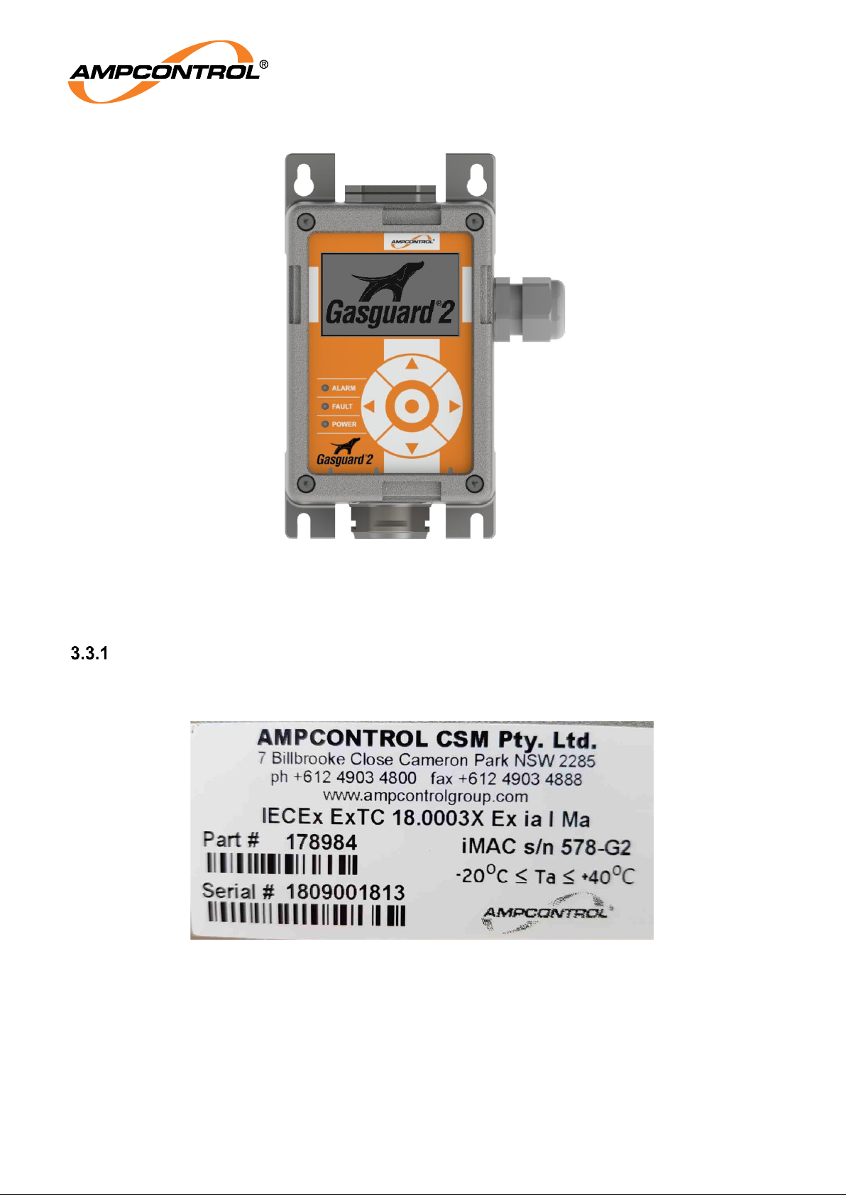
The GG2 Display is available in three variants, a glanded display supporting iMAC/RS485
communication and two pluggable versions supporting 4-20mA+iMAC and 4-20mA+RS485
communication. The display connects to a variety of compatible detector modules via the robust
proprietary connector. An optional Remote Cable Assembly is available for mounting compatible
modules up to 10 metres from the GG2 Display.
3.2 Key Features
Certified Intrinsically Safe – Ex ia I Ma
Rugged stainless steel construction
Failsafe architecture and digital interface
Extensive self-diagnostic routines
Economical
LCD Display
4-20mA, iMAC and RS485 communication support
Compatible with a wide range of detectors:
o Electrochemical
Carbon Monoxide (CO)
Oxygen (O2)
Hydrogen Sulphide (H2S)
o Catalytic
Methane (CH4)
o Non-Dispersive Infrared
Methane (CH4)
Carbon Dioxide (CO2)
Backwards compatible with Ampcontrol’s existing Gasguard equipment*
*note: While mounting points remain the same, the additional space required by the GG2 Display/Sensor
assembly must be taken into account. The remote head assembly will require a bracket modification to
mount the detector.
Figure 1: GG2 Example System (iMAC Communication)
iMAC Fieldbus
Page 14
Ampcontrol Pty Ltd – ABN 28 000 915 542
GG2 DISPLAY USER MANUAL
GG2B023
Version 5 – NOVEMBER/2020
Uncontrolled Copy - Refer to Ampcontrol Website for Latest Version
Page 14 of 62
APPROVED FOR EXTERNAL DISTRIBUTION
– PROPERTY OF AMPCONTROL PTY LTD
– NOT TO BE REPRODUCED IN PART
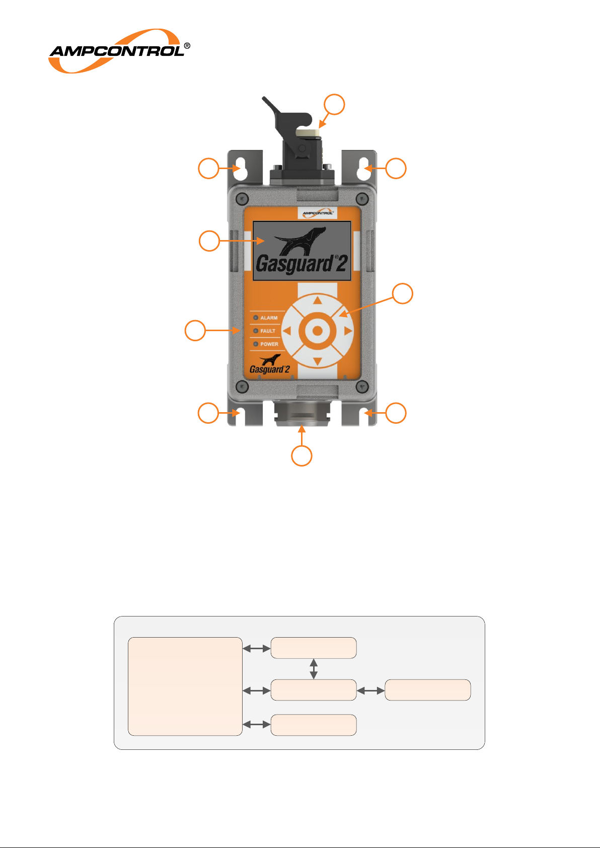
Figure 2: GG2 Display Overview
1.
LCD Display
2.
LED Indicators
3.
Proprietary Connector (S2)
4.
Magnetic Keypad
5.
System Connector (S1)
6.
Mounting Tabs
IP Display Enclosure
GG2 Display Module
IECEx TRA 18.0003X
IECEx ITA 07.0017X
System Plug (S1)
Terminal Strip
Sensor Plug (S2)
Gland (Optional)
Figure 3: GG2 Display Block Diagram
2
1
6
5
4
3
6
6
6
Page 15
Ampcontrol Pty Ltd – ABN 28 000 915 542
GG2 DISPLAY USER MANUAL
GG2B023
Version 5 – NOVEMBER/2020
Uncontrolled Copy - Refer to Ampcontrol Website for Latest Version
Page 15 of 62
APPROVED FOR EXTERNAL DISTRIBUTION
– PROPERTY OF AMPCONTROL PTY LTD
– NOT TO BE REPRODUCED IN PART
Figure 4: Glanded GG2 Display
3.3 Markings
GG2 Display
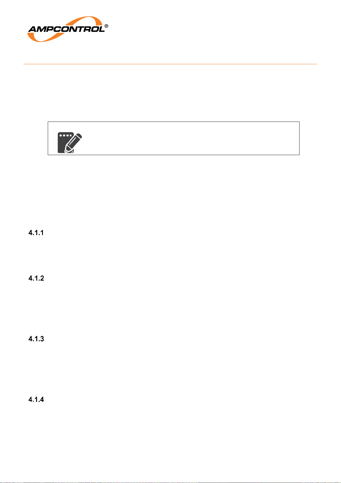
The GG2 Display Marking is shown below in Figure 5
Figure 5: GG2 Display Marking
Page 16

Ampcontrol Pty Ltd – ABN 28 000 915 542
GG2 DISPLAY USER MANUAL
GG2B023
Version 5 – NOVEMBER/2020
Uncontrolled Copy - Refer to Ampcontrol Website for Latest Version
Page 16 of 62
APPROVED FOR EXTERNAL DISTRIBUTION
– PROPERTY OF AMPCONTROL PTY LTD
– NOT TO BE REPRODUCED IN PART
GG2 Display Module
The Certified GG2 Display module has the following marking information inside the GG2 Display.
Table 1: Minimum Marking Information
THE MINIMUM MARKING
MUST CONTAIN THE
INFORMATION
AMPCONTROL
GG2 DISPLAY MODULE
IECEx TRA 18.0003X
Ex ia I Ma
-20°C ≤ Ta ≤ +40°C
SERIAL: XXXXX
3.4 Enclosure
Stainless steel housing
The GG2 Display circuitry is incorporated in a stainless steel housing. The housing is robust and
corrosion resistant installation.
Ingress protection rating
The GG2 Display has been designed fit for purpose for the harsh environment of an underground
coalmine.
The enclosure and electrical connection when mated achieves IP66.
3.5 Certification
Entity parameters listed on the certificate must be taken into account during system commissioning.
The apparatus is designed to be used in hazardous areas and is certified intrinsically safe IECEx TRA
18.0003X. The controlled version of this certificate can be found on the IECEx website
http://iecex.iec.ch/iecex/exs.nsf/ex_eq.xsp?v=e
The GG2 Display is compliant with the following standards:
o IEC 60079-0: 2011 Ed 6.0 Explosive atmospheres - Part 0: General requirements
o IEC 60079-11: 2011 Ed 6.0 Explosive atmospheres - Part 11: Equipment protection by
intrinsic safety “I”
The detector is in conformance with IEC60079.11, section 6.3.13
The detector is in conformance to IEC60079.0, section 7.4.2
Page 17
Ampcontrol Pty Ltd – ABN 28 000 915 542
GG2 DISPLAY USER MANUAL
GG2B023
Version 5 – NOVEMBER/2020
Uncontrolled Copy - Refer to Ampcontrol Website for Latest Version
Page 17 of 62
APPROVED FOR EXTERNAL DISTRIBUTION
– PROPERTY OF AMPCONTROL PTY LTD
– NOT TO BE REPRODUCED IN PART
4 INSTALLATION
The GG2 Display Module is suitable for installation in Group I hazardous areas when housed in an
enclosure suitable for group I that provides a degree of protection not less than IP54 as per IEC 60529.
The GG2 Display is a suitable enclosure to house the GG2 Display Module and has been designed to
connect and mount to other compatible modules. Contact Ampcontrol for the latest range of compatible
modules.
NOTE
The GG2 Display is suitable for installation in Group 1 hazardous areas.
4.1 General Warnings
These instructions have been designed to assist users of the GG2 Display with installation.
Before the unit can be installed, there are a number of things that need to be considered and understood
to prevent incorrect or unsafe operation of the unit or the system into which it is installed. Along with
relevant competence, and an understanding of the target application, the following points should be
considered:
Ensure that the information provided in this user manual is fully understood.
It is extremely important that the limitations and functionality of the unit are understood to prevent
incorrect installation and use from creating a potentially dangerous risk. If in doubt as to the nature of
the limitations or their implication, consult a competent authority such as a supervisor or Ampcontrol
technical representative.
Ensure that the application into which the unit is being installed has been properly
defined, designed, and approved.
Any system intended to mitigate the risk of injury needs to be properly designed and implemented.
Such a system must be the result of structured risk analysis with the outcomes used to define the
system requirements. These requirements, in turn, will guide the choice of instrumentation, logic
solvers, and actuators needed to implement the system. Understanding the needs of the system will
ensure proper selection of equipment.
Ensure that the unit will properly perform the required functions within the system
design.
It is important to understand how the unit is intended to interact with other equipment within a system.
For safe and reliable use, it is crucial that neither the unit’s logical operation nor its signalling be
compromised by incompatibilities with connected equipment. For Group I installations, a full Intrinsic
Safety Audit will be required, along with a correctly specified Safety File. Contact Ampcontrol for
engineering services to undertake these assessments.
Modifications of any form to the unit are prohibited.
The unit as supplied has been designed and manufactured to comply with the requirements of
protection and performance standards. If modifications of any form are made to the unit, the equipment
may no longer be fit for use. If any modifications or damage to the unit is evident, do not use the
equipment and contact Ampcontrol for advice.
Page 18
Ampcontrol Pty Ltd – ABN 28 000 915 542
GG2 DISPLAY USER MANUAL
GG2B023
Version 5 – NOVEMBER/2020
Uncontrolled Copy - Refer to Ampcontrol Website for Latest Version
Page 18 of 62
APPROVED FOR EXTERNAL DISTRIBUTION
– PROPERTY OF AMPCONTROL PTY LTD
– NOT TO BE REPRODUCED IN PART
4.2 Mandatory Installation Practices
The following information must be adhered to when installing the GG2 Display. Failure to adhere to this
information may give rise to unsafe operation.
Using the unit in a manner that exceeds its electrical, functional or physical specifications, or in a way
that is contrary to its operating restrictions, may result in equipment malfunction or loss of performance.
The unit must be powered within the specified voltage range.
The installation of the unit must be carried out by suitably trained and qualified personnel.
Identification labels fixed to the unit must not be damaged, removed or covered before, during or
after installation.
The installation is to be in accordance with the relevant installation Standards/Codes of Practice.
Modifications must not be made to any part of the unit. As supplied, the unit is built to, and
complies with the relevant standards. Modifications to its construction will render the unit noncompliant.
Complete and accurate records of the installation must be kept as part of the site installation.
Confirm the Intrinsically Safe parameters of the GG2 Detector, cables and power supply are
suitable for the application.
Ensure that the Conditions of Safe Use, listed in the certificate, are adhered to.
4.3 Conditions of Safe Use
1. The following input parameters are to be taken in to account in the system:
NOTE
Refer to the IECEx website for the latest controlled documentation.
Table 2: Optional Marking Information
OPTIONAL MARKING INFORMATION:
CONNECTION
FUNCTION
PINS
NAME
PARAMETERS
SYSTEM
VIN
NOTE3
P2-3 TO P2-
1/P1-4
VIN TO GND
UI:16.5V
CI: NEGLIGIBLE
NOTE1
LI:
NEGLIGIBLE
NOTE1
4-20mA
NOTE3
P2-2 TO P2-
1/P1-4
4-20mA TO GND
UI:16.5V
CI: NEGLIGIBLE
NOTE1
LI:
NEGLIGIBLE
NOTE1
RS485
P3-1/P3-2 TO
P2-1/P1-4
RS485+/RS485- TO
GND
UI: 7.14V
CI: NEGLIGIBLE
LI: NEGLIGIBLE
UO: 5.88V
IO: 41.47 MA
PO: 62.2MW
IMAC
P3-3 TO P3-4
L1+ TO L1--
UI: 21.5V
PI: 2.66W
CI: NEGLIGIBLE
LI: NEGLIGIBLE
Page 19
Ampcontrol Pty Ltd – ABN 28 000 915 542
GG2 DISPLAY USER MANUAL
GG2B023
Version 5 – NOVEMBER/2020
Uncontrolled Copy - Refer to Ampcontrol Website for Latest Version
Page 19 of 62
APPROVED FOR EXTERNAL DISTRIBUTION
– PROPERTY OF AMPCONTROL PTY LTD
– NOT TO BE REPRODUCED IN PART
OPTIONAL MARKING INFORMATION:
CONNECTION
FUNCTION
PINS
NAME
PARAMETERS
SENSOR
VOUT
NOTE3
P1-3 TO P2-
1/P1-4
VOUT TO GND
POWER FEED THROUGH
UI:16.5V
CI: NEGLIGIBLE
LI: NEGLIGIBLE
UO:
NOTE2
IO:
NOTE2
DATA
NOTE3
P1-2/P1-1 TO
P2-1/P1-4
DATA+/DATA- TO
GND
UI:16.5V
CI: NEGLIGIBLE
LI: NEGLIGIBLE
NOTE 1: THE CI AND LI FROM THE MODULE IS NEGLIGIBLE HOWEVER ANY CABLE OR LUMPED
PARAMETERS APPLIED AT THE FEED THROUGH CONNECTION P1-3, P1-4 MUST BE TAKEN
INTO ACCOUNT IN THE POWER SUPPLY’S ENTITY BALANCE.
NOTE 2: UO AND IO ARE EQUAL TO THE APPLIED UO AND IO FROM THE SUPPLY APPLIED AT P2-3
AND P2-1
NOTE 3: VIN, 4-20MA, VOUT AND DATA CONNECTIONS MAY BE CONSIDERED AS A SINGLE SET
OF INPUT PARAMETERS WITH THE LUMPED PARAMETERS CONNECTED AT THE SENSOR
INTERFACE TAKEN INTO ACCOUNT IN THE POWER SUPPLY’S ENTITY BALANCE
NOTE 4: P2-4 IS THE ISOLATED CHASSIS CONNECTION
2. The GG2 Display Module must be housed in an enclosure suitable for Group I that provides a
degree of protection not less than IP54 as per IEC 60529.
WARNING!
The connections shown above are for the certified GG2 Display Module
housed within the GG2 Display.
The external connections for the GG2 Display are detailed in Section 0.
4.4 Mechanical Installation Information
To ensure continued reliable operation of the GG2 Display, the following should be considered when
mounting the unit:
Select a suitable central location for mounting with good access. The location should be as clean
and dry as practicable and at a temperature as close to 20°C as practicable.
Mount the display in a position that reduces the risk of mechanical damage.
Mounting should be to a vertical surface, allowing for easy access and subsequent servicing.
The installation requirements of any connected sensors shall be taken into account
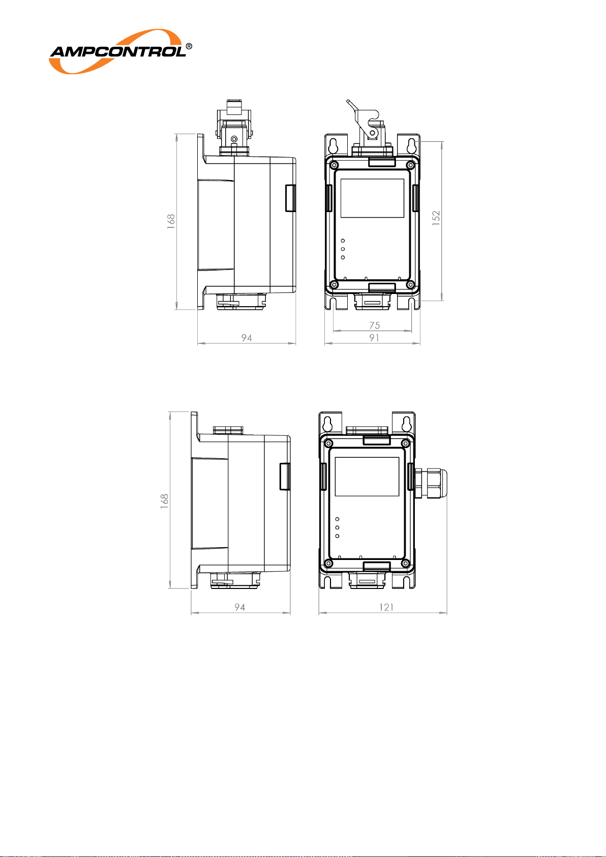
Dimensions
While mounting points are backwards compatible with Ampcontrol’s existing Gasguard equipment, the
additional space required by the GG2 Display/Sensor assembly must be taken into account during
installation. The remote head assembly will require a bracket modification to mount the detector.
Page 20
Ampcontrol Pty Ltd – ABN 28 000 915 542
GG2 DISPLAY USER MANUAL
GG2B023
Version 5 – NOVEMBER/2020
Uncontrolled Copy - Refer to Ampcontrol Website for Latest Version
Page 20 of 62
APPROVED FOR EXTERNAL DISTRIBUTION
– PROPERTY OF AMPCONTROL PTY LTD
– NOT TO BE REPRODUCED IN PART
Figure 6: GG2 Display Dimensions (mm)
Figure 7: Glanded GG2 Display Dimensions (mm)
Page 21
Ampcontrol Pty Ltd – ABN 28 000 915 542
GG2 DISPLAY USER MANUAL
GG2B023
Version 5 – NOVEMBER/2020
Uncontrolled Copy - Refer to Ampcontrol Website for Latest Version
Page 21 of 62
APPROVED FOR EXTERNAL DISTRIBUTION
– PROPERTY OF AMPCONTROL PTY LTD
– NOT TO BE REPRODUCED IN PART
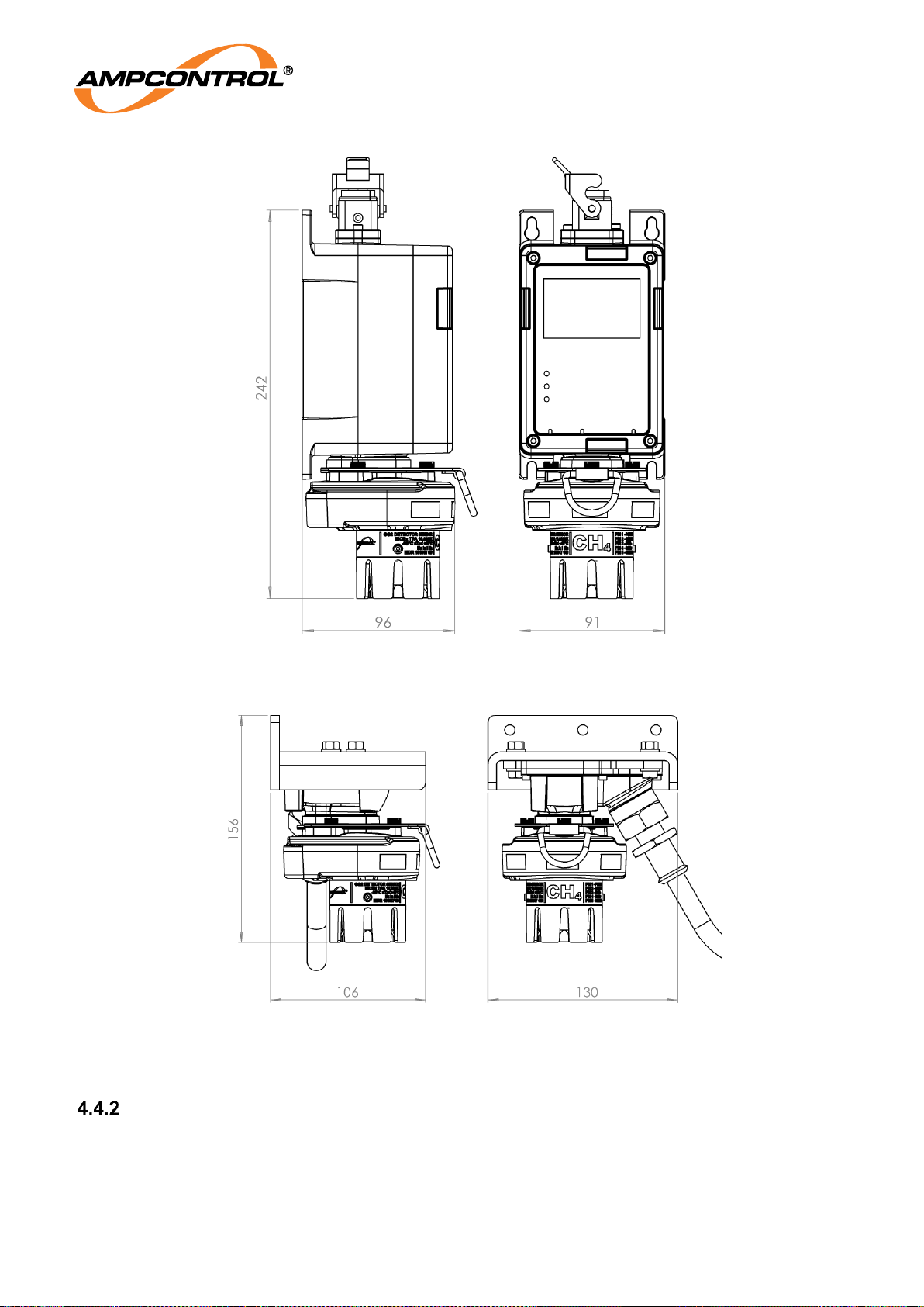
Figure 8: GG2 Display and CH4 Detector Dimensions (mm)
Figure 9: GG2 Remote Cable Assembly Dimensions (mm)
Mounting Arrangements
4.4.2.1 GG2 Display
The GG2 Display is mounted using the four screw tabs. The custom plug interface allows subsequent
mounting of compatible modules. Optionally, the compatible modules may be mounted up to 10 meters
away using the optional remote cable assembly. Refer to Figure 6 for mounting hole locations.
Page 22
Ampcontrol Pty Ltd – ABN 28 000 915 542
GG2 DISPLAY USER MANUAL
GG2B023
Version 5 – NOVEMBER/2020
Uncontrolled Copy - Refer to Ampcontrol Website for Latest Version
Page 22 of 62
APPROVED FOR EXTERNAL DISTRIBUTION
– PROPERTY OF AMPCONTROL PTY LTD
– NOT TO BE REPRODUCED IN PART
4.4.2.2 GG2 Remote Cable Assembly
The GG2 Remote Cable Assembly is mounted hanging down from a flat surface using the three screw
tabs. The custom plug interface allows subsequent mounting of compatible modules. Refer to Figure 9
for mounting hole locations. The three mounting holes are spaced 50mm on centre.
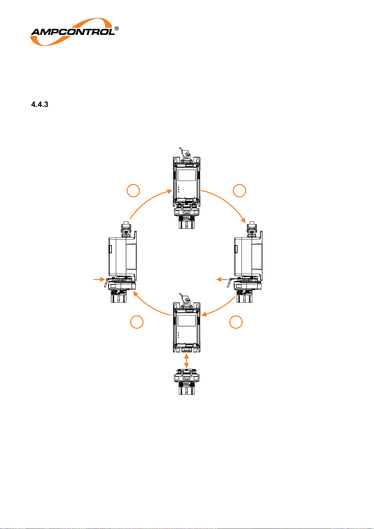
Connecting and Disconnecting a GG2 Detector
The process for connecting and disconnecting the GG2 Detector is outlined in Figure 10 and detailed in
the following subsections. The detector must be isolated or in sleep mode prior to
connection/disconnection. Refer to Section 5.3 for more information.
Figure 10: Connecting/Disconnection Detector
4.4.3.1 Disconnecting Detector
1. Release the retainer clip by pulling firmly away from the display. Ensure the detector is supported
at all times to prevent potential damage.
2. After releasing the retainer clip, release the detector by pulling the detector firmly downwards.
4.4.3.2 Connecting Detector
3. Connect the detector to the GG2 Display via the proprietary connector. Press firmly to ensure the
connection is fully engaged. Support the detector until the retainer clip is secured.
4 1
23
Page 23
Ampcontrol Pty Ltd – ABN 28 000 915 542
GG2 DISPLAY USER MANUAL
GG2B023
Version 5 – NOVEMBER/2020
Uncontrolled Copy - Refer to Ampcontrol Website for Latest Version
Page 23 of 62
APPROVED FOR EXTERNAL DISTRIBUTION
– PROPERTY OF AMPCONTROL PTY LTD
– NOT TO BE REPRODUCED IN PART
4. Secure the retainer clip by pushing it fully rearwards. The pull ring should be in line with the
detector housing.
NOTE
The detector must be isolated or in sleep mode prior to
connection/disconnection. Refer to Section 5.3 for more information.
NOTE
Ensure that the dust covers are in place when the GG2 Display is not in
use.
4.5 Electrical Installation Information
Compatible Module
The GG2 Display is a part of a GG2 range of products and is designed to interface directly with
compatible modules. Contact Ampcontrol for a current list of compatible modules.
Remote Cable Assembly
The compatible modules can be mounted remotely from the GG2 Display using the GG2 remote cable
assembly. The cable is supplied in 10 metre lengths and cut to size. The cable is pre-terminated at the
detector end and contains white cores numbered “one”, “two”, “three” and “four” with black text.
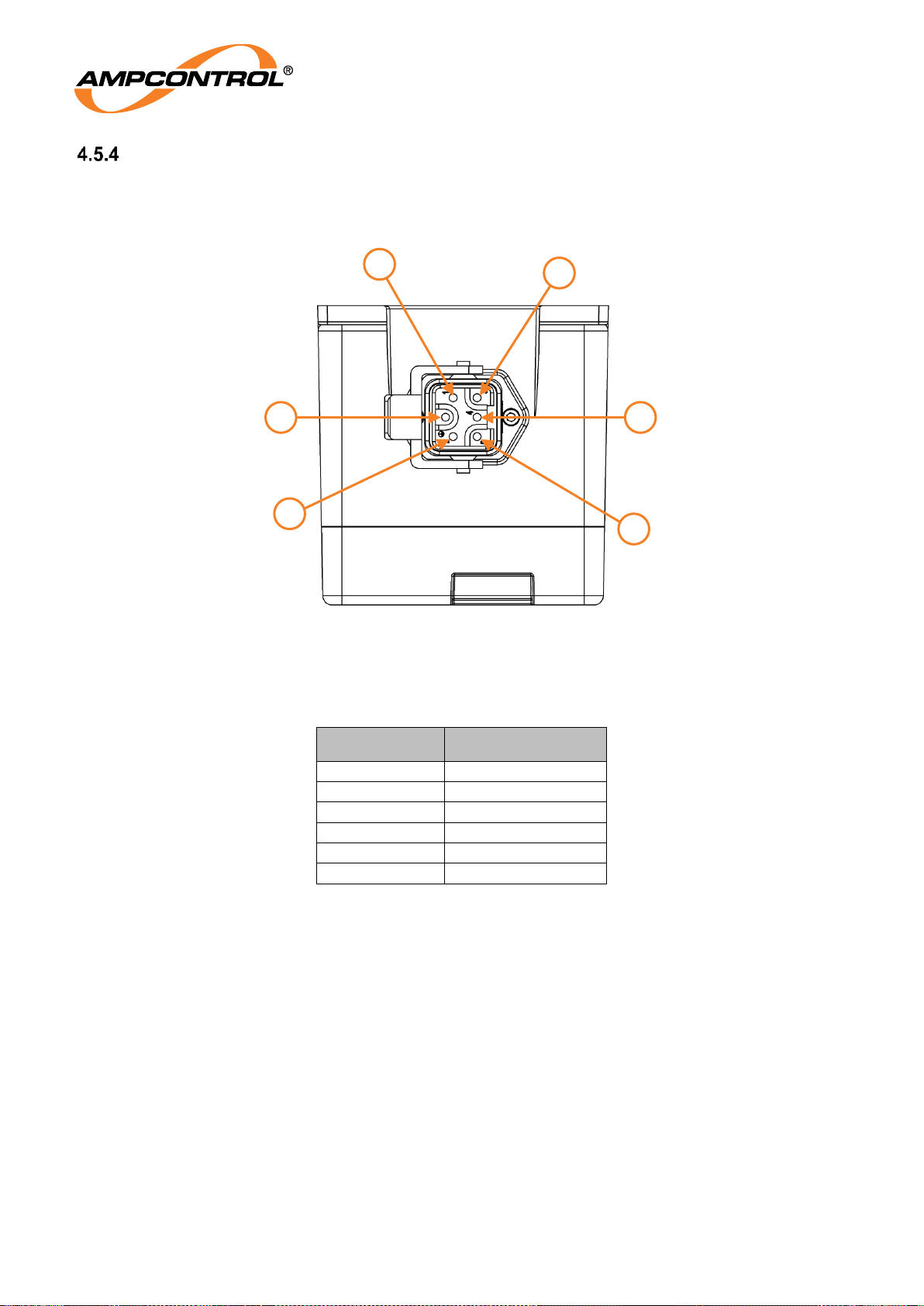
Table 3: Remote Cable Connections
Remote Cable
Function
Core 1
Power
Core 2
Ground
Core 3
Data -
Core 4
Data +
Earth (Screen)
Chassis
Earthing Procedures
The metallic GG2 Display chassis is connected to S1 Pin 6 and S2 Pin 5.
The GG2 Detector passes the 500V dielectric strength test between intrinsically safe circuits and the
metallic enclosure S1 Pin 6 and P2 Pin 5.
NOTE
The detector is in conformance to IEC60079.0, section 7.4.2 Dielectric
strength requirement
Page 24
Ampcontrol Pty Ltd – ABN 28 000 915 542
GG2 DISPLAY USER MANUAL
GG2B023
Version 5 – NOVEMBER/2020
Uncontrolled Copy - Refer to Ampcontrol Website for Latest Version
Page 24 of 62
APPROVED FOR EXTERNAL DISTRIBUTION
– PROPERTY OF AMPCONTROL PTY LTD
– NOT TO BE REPRODUCED IN PART
Detector Wiring and Connectors
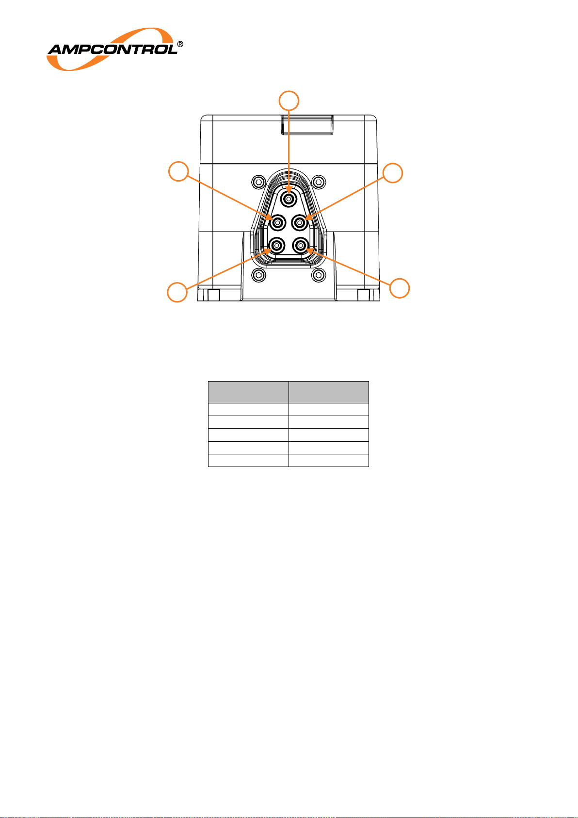
The GG2 Display has two connection facilities. S1 for the system interface and S2 for the sensor
interface. The connector pins are shown below.
Figure 11: GG2 Display System (S1) Connector (Top) Pin Out
Table 4: GG2 Display System (S1) Connector Pin Out
Pin
Function
S1 – 1
Data +
S1 – 2
+VDC
S1 – 3
0VDC
S1 – 4
Data -
S1 – 5
4-20mA OUT
S1 – 6
Screen (not used)
3
1
6 4
5
2
Page 25
Ampcontrol Pty Ltd – ABN 28 000 915 542
GG2 DISPLAY USER MANUAL
GG2B023
Version 5 – NOVEMBER/2020
Uncontrolled Copy - Refer to Ampcontrol Website for Latest Version
Page 25 of 62
APPROVED FOR EXTERNAL DISTRIBUTION
– PROPERTY OF AMPCONTROL PTY LTD
– NOT TO BE REPRODUCED IN PART
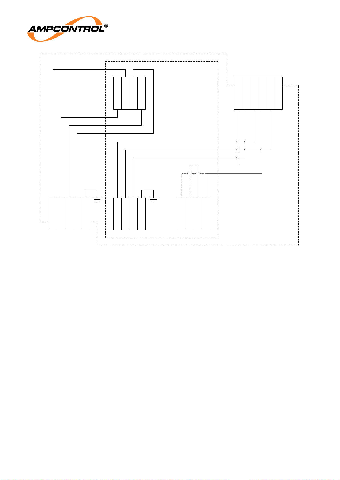
1
5
2
4
3
Figure 12: GG2 Display Sensor (S2) Connector (Bottom) Pin Out
Table 5: GG2 Display Sensor (S2) Connector Pin Out
Pin
Function
S2 – 1
Power
S2 – 2
Ground
S2 – 3
Data -
S2 – 4
Data +
S2 – 5
Chassis
Page 26
Ampcontrol Pty Ltd – ABN 28 000 915 542
GG2 DISPLAY USER MANUAL
GG2B023
Version 5 – NOVEMBER/2020
Uncontrolled Copy - Refer to Ampcontrol Website for Latest Version
Page 26 of 62
APPROVED FOR EXTERNAL DISTRIBUTION
– PROPERTY OF AMPCONTROL PTY LTD
– NOT TO BE REPRODUCED IN PART
GND
4-20mA
VIN
CHASSIS
RS485-
RS485+
L+
L-
GND
VOUT
DATA+
DATA-
V+
V-
Data-
Data+
EARTH
Data+
V+
0VDC
Data-
4-20mA
SCREEN
GG2 Display
Module
S2
P1
P2 P3
System Connector
1 1 1
1
Detector Connector
Alternate
Connections
1
GG2 Display Enclosure
(System Connector)
Figure 13: Electrical Connections - Display Enclosure with System Connector
Page 27
Ampcontrol Pty Ltd – ABN 28 000 915 542
GG2 DISPLAY USER MANUAL
GG2B023
Version 5 – NOVEMBER/2020
Uncontrolled Copy - Refer to Ampcontrol Website for Latest Version
Page 27 of 62
APPROVED FOR EXTERNAL DISTRIBUTION
– PROPERTY OF AMPCONTROL PTY LTD
– NOT TO BE REPRODUCED IN PART
GND
4-20mA
VIN
CHASSIS
RS485-
RS485+
L+
L-
GND
VOUT
DATA+
DATA-
V+
V-
Data-
Data+
EARTH
V+
4-20mA
V-
RS485-
RS485+
L1+
L1-
SCREEN
GG2 Display
Module
GG2 Display Enclosure
(Glanded version)
S2
P1
P2 P3
Terminal Strip
1 1 1
1
Detector
1
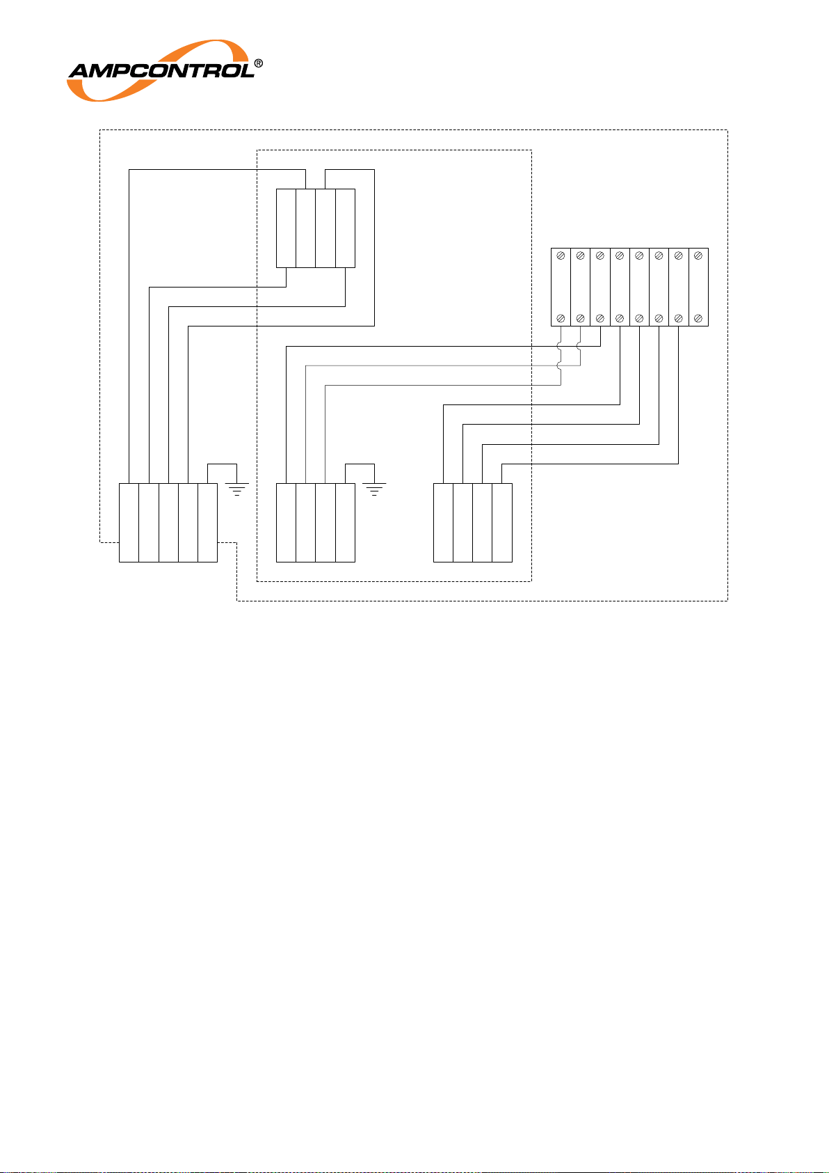
Figure 14: Electrical Connections - Display Enclosure with Glanded Connector
Page 28
Ampcontrol Pty Ltd – ABN 28 000 915 542
GG2 DISPLAY USER MANUAL
GG2B023
Version 5 – NOVEMBER/2020
Uncontrolled Copy - Refer to Ampcontrol Website for Latest Version
Page 28 of 62
APPROVED FOR EXTERNAL DISTRIBUTION
– PROPERTY OF AMPCONTROL PTY LTD
– NOT TO BE REPRODUCED IN PART
5 PRODUCT OPERATION
The GG2 Display is an integral part of an environmental monitoring system. The GG2 Display provides
the user interface for gas detectors and facilitates the interface to communication system infrastructure.
The GG2 Display has the following interface options:
Modbus – refer to Section 5.4.3
iMAC – refer to Section 5.4.4
4-20mA analogue output – refer to Section 5.4.5
The GG2 Display communicates with compatible modules such as the GG2 Detector using a robust
digital communication protocol. The GG2 Display is fully compatible with the GG2 Detector’s digital
interface.
5.1 Human-Machine Interface
The GG2 Display is controlled via the HMI. The system is menu driven and navigated via the magnetic
keypad outlined in Figure 2. Refer to Section 5.1.1 for an overview of the magnetic keypad operation.
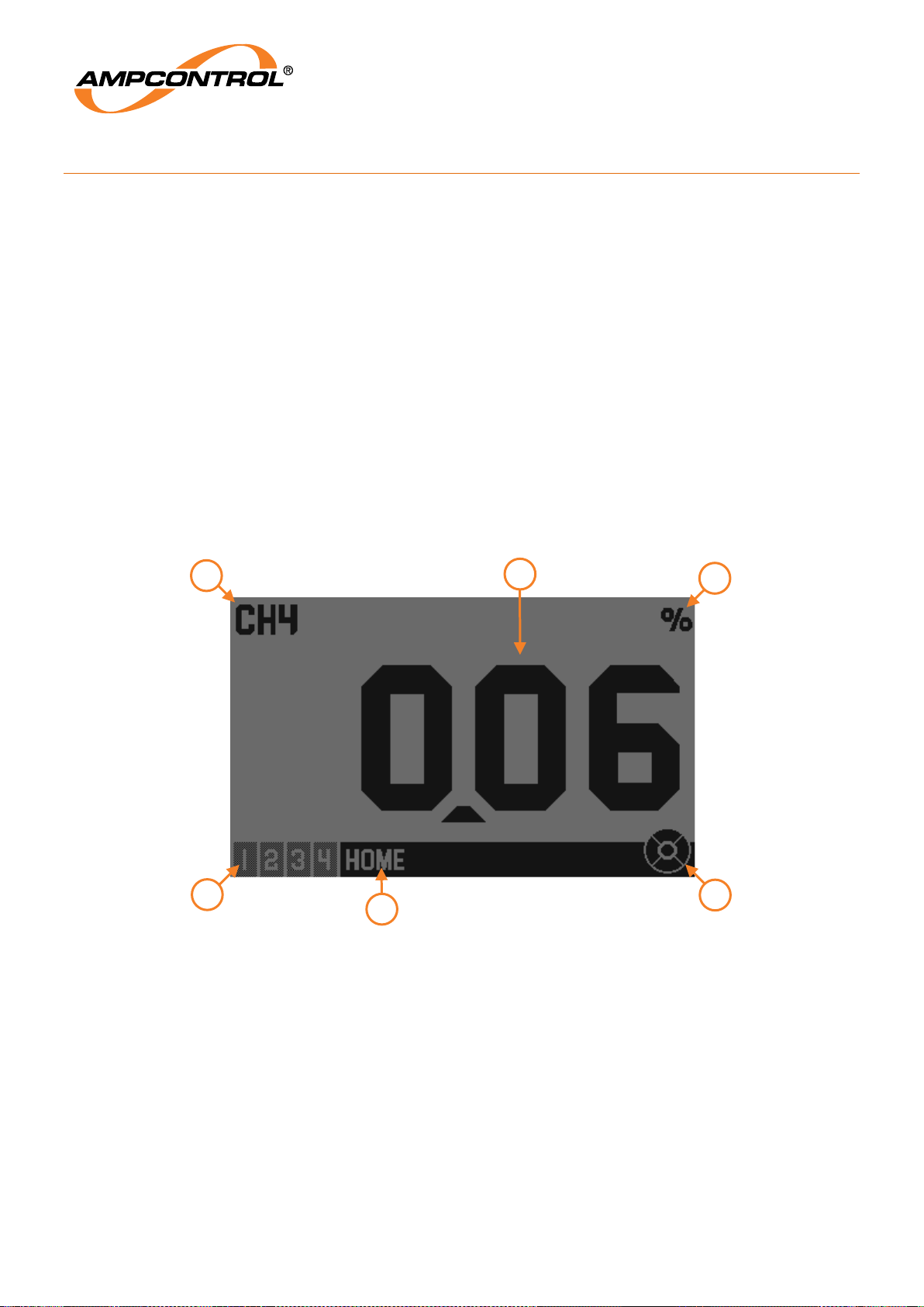
The HOME screen of the GG2 Display will appear similar to that of Figure 15. The interface has a
number of features identified in this image numbered circles. Items identified in this figure are detailed
below.
Figure 15: GG2 Display UI Home Screen Example
Item 1: Menu Title – Displays the name of the current menu selection. For an overview of the
menu structure, refer to Section 5.1.2.
Item 2: Menu Level – This area of the display indicates the current menu level.
Item 3: Gas Type – Indicates the gas type for the GG2 Detector connected to the display.
Item 4: Detector Reading – Indicates the current detector reading.
Item 5: Gas Units – Indicates the units of the current detector reading.
Item 6: Keypad Guide – these correspond to the five reed switches located on the front of the
GG2 Display.
5
6
4
2
3
1
Page 29
Ampcontrol Pty Ltd – ABN 28 000 915 542
GG2 DISPLAY USER MANUAL
GG2B023
Version 5 – NOVEMBER/2020
Uncontrolled Copy - Refer to Ampcontrol Website for Latest Version
Page 29 of 62
APPROVED FOR EXTERNAL DISTRIBUTION
– PROPERTY OF AMPCONTROL PTY LTD
– NOT TO BE REPRODUCED IN PART
Navigating the User Interface
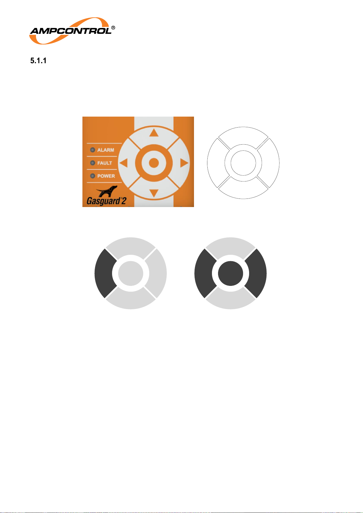
The user interface is controlled via the magnetic keypad on the front of the GG2 Display, refer to Figure
16. The keypad requires the magnetic wand to activate the five magnetic reed switches located directly
beneath the orange symbols. The valid keypad events will vary according to the current menu selection.
The GG2 Display’s keypad guide (Item 6 of Figure 15) illustrates which keypad events will be accepted
for the current menu selection. The dark segments represent valid keypad events while the lighter keys
represent invalid keypad events, refer to Figure 17.
Figure 16: Keypad Overview
Figure 17: Keypad Guide
5.1.1.1 Using the Magnetic Wand
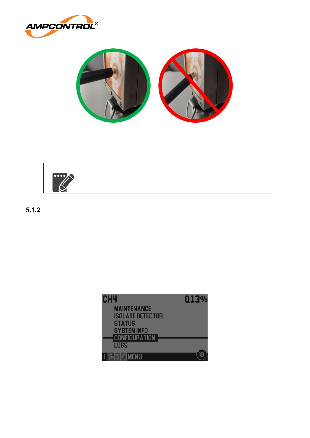
For best results during operation of the GG2 Display, the display should be at eye level and the following
points should be observed.
To activate a button/switch:
o Move the magnetic wand to the desired segment of the keypad whilst keeping the wand
approximately 5cm away from the display.
o Move it in a direction perpendicular to the display until the keypad operation is registered.
A small amount of lateral movement is tolerable as long as other segments are not
crossed.
For consecutive button/switch events, it is important that the magnetic wand is moved far enough
away (approximately 5cm) from the keypad, such that the previous keypress is cleared, before
the next keypress is made.
ENTER
UP
DOWN
LEFT RIGHT
Keypad Guide showing only the LEFT
key available
Keypad Guide showning only the LEFT,
RIGHT and ENTER keys available
Page 30
Ampcontrol Pty Ltd – ABN 28 000 915 542
GG2 DISPLAY USER MANUAL
GG2B023
Version 5 – NOVEMBER/2020
Uncontrolled Copy - Refer to Ampcontrol Website for Latest Version
Page 30 of 62
APPROVED FOR EXTERNAL DISTRIBUTION
– PROPERTY OF AMPCONTROL PTY LTD
– NOT TO BE REPRODUCED IN PART
Figure 18: Using the Magnetic Wand
NOTE
For best results, the magnetic wand should be orientated horizontally to
the GG2 Display.
Menu Overview
The GG2 Display’s menu has been implemented in a tree structure to provide an intuitive interface for
interacting with the various features and configuration options provided. The menu can be accessed
after completion of the system boot sequence. From the HOME screen, the menu is accessed by
pressing any of the five segments of the magnetic keypad. Once in the menu, the current menu level will
be shown (Item 2 of Figure 15) along with the title of the current menu (Item 1 of Figure 15).
The selected menu option is identified by the black horizontal line running across the display and the
black box bounding the text, refer to Figure 19. Actioning up or down on the keypad will move the
selection up or down respectively, the selection will wrap around once the top or bottom has been
reached. To return to the previous menu level action left on the magnetic keypad. Repeatedly actioning
left will eventually return the user to the HOME screen. Actioning right on the magnetic keypad will take
the user into the selected menu.
Figure 19: Menu Level 1 (Configuration Option Selected)
Apply the magnetic wand
perpendicular to the magnetic keypad
Do not apply the magnetic
wand at any other angle
Page 31

Ampcontrol Pty Ltd – ABN 28 000 915 542
GG2 DISPLAY USER MANUAL
GG2B023
Version 5 – NOVEMBER/2020
Uncontrolled Copy - Refer to Ampcontrol Website for Latest Version
Page 31 of 62
APPROVED FOR EXTERNAL DISTRIBUTION
– PROPERTY OF AMPCONTROL PTY LTD
– NOT TO BE REPRODUCED IN PART
The following provides an overview of the menu options.
Maintenance
o Gas Calibration (Electrochemical and Catalytic)
Zero Adjustment
Span Adjustment
ILAC Linearity Test (Requires authorisation)
o Gas Calibration (NDIR)
Scaling Adjustment
ILAC Linearity Test
o Response Test
o Telemetry Test
o System Resets
Reset Last Peak Value
Factory Default Reset (Requires authorisation)
Reset latched catalytic (Catalytic GG2 Detectors only, Requires authorisation)
o LED Indication Test
Isolate Detector
Status
System Info
o Pg1 Configuration data
o Pg2 Modbus or iMAC configuration data
o Pg3 Display data
o Pg4 Detector data
o Pg5 Last Min/Peak values
Configuration (Requires authorisation)
o 4-20 mA Setup
4-20 mA Settings
4 mA Calibration
20 mA Calibration
o Setpoints
o Protocol Select
o Protocol Config (Behaviour is dependent on selected protocol)
With Modbus selected
Settings
With iMAC selected
Addresses
General
Logs
o Detector Logs
o Display Logs
5.1.2.1 Menu Authorisation
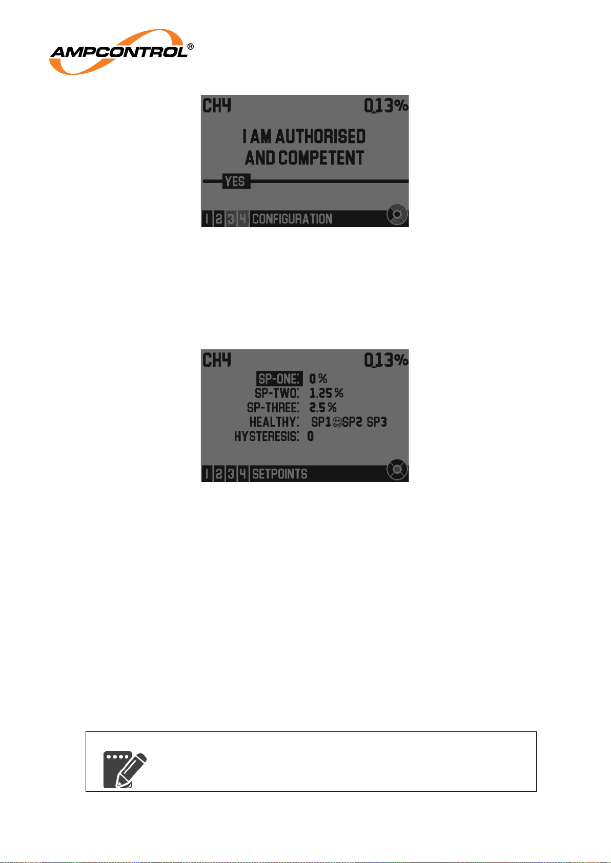
Certain functions of the GG2 Display may only be completed by authorised and competent personnel.
Before proceeding with these functions, an authorisation screen is presented to the user, refer to Figure
20. The authorisation screen may either be acknowledged with a centre keypad action or cancelled by
actioning left. Cancelling will return the user to the previous menu selection.
Page 32
Ampcontrol Pty Ltd – ABN 28 000 915 542
GG2 DISPLAY USER MANUAL
GG2B023
Version 5 – NOVEMBER/2020
Uncontrolled Copy - Refer to Ampcontrol Website for Latest Version
Page 32 of 62
APPROVED FOR EXTERNAL DISTRIBUTION
– PROPERTY OF AMPCONTROL PTY LTD
– NOT TO BE REPRODUCED IN PART
Figure 20: Menu Authorisation
5.1.2.2 Parameter Changes
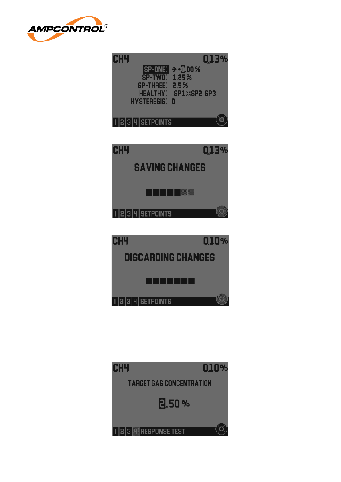
Most of the configuration screens are organised in the following uniform way, such as the setpoints
configuration screen, represented below in Figure 21. Each adjustable field is represented on a single
line and the menu may be navigated similarly to the menu previously described. Fields can be selected
by actioning up or down on the magnetic keypad and the selection will wrap around upon reaching the
top or bottom.
Figure 21: Setpoints Configuration Screen
To edit the selected field, press right. Edit mode is indicated by the right arrow on the selected field as
shown in Figure 22. The example shown in this figure is of a numerical field and accepts a large range of
values, including negative values. Fields that will accept negative values will contain a positive or a
negative sign. To set the desired value, action right to select the character (digit or sign) you wish to
change and press the up or down key/s to increase or decrease the value. The values will wrap around.
To select a different character, press the left or right key. Moving to the right will result in wrap around on
the digit selection. By pressing left and navigating past the first digit, edit mode can be exited. Changes
are temporarily stored while the user remains in the current menu level.
To save changes press enter when in field selection mode. The saving changes screen will appear as
shown in Figure 23. It is possible to make several changes and perform a bulk save provided the user
does not navigate out of the menu level. Some options are not numerical, but have several possibilities.
These fields are edited and saved in the same way as the numerical fields.
By pressing left when in field selection mode the option menu will be exited. If changes were made the
abandoning changes screen, as shown in Figure 24, will be shown briefly and the changes will be lost.
NOTE
Pressing left and navigating out of the menu level will discard all
changes.
Page 33
Ampcontrol Pty Ltd – ABN 28 000 915 542
GG2 DISPLAY USER MANUAL
GG2B023
Version 5 – NOVEMBER/2020
Uncontrolled Copy - Refer to Ampcontrol Website for Latest Version
Page 33 of 62
APPROVED FOR EXTERNAL DISTRIBUTION
– PROPERTY OF AMPCONTROL PTY LTD
– NOT TO BE REPRODUCED IN PART
Figure 22: Numerical field edit mode
Figure 23: Save Screen
Figure 24 - Discarding Changes Screen
Several screens within the menu structure require the operator to enter a single value and appear similar
to that of Figure 25, below. A value editor can be identified when a displayed number has a single
highlighted character (digit or sign). These screens will function similarly to that described above with the
exception that moving left past the leftmost digit will exit the screen and only one value may be changed
at a time.
Figure 25 - Response test target value editor
Page 34
Ampcontrol Pty Ltd – ABN 28 000 915 542
GG2 DISPLAY USER MANUAL
GG2B023
Version 5 – NOVEMBER/2020
Uncontrolled Copy - Refer to Ampcontrol Website for Latest Version
Page 34 of 62
APPROVED FOR EXTERNAL DISTRIBUTION
– PROPERTY OF AMPCONTROL PTY LTD
– NOT TO BE REPRODUCED IN PART
5.2 System States
Display Boot
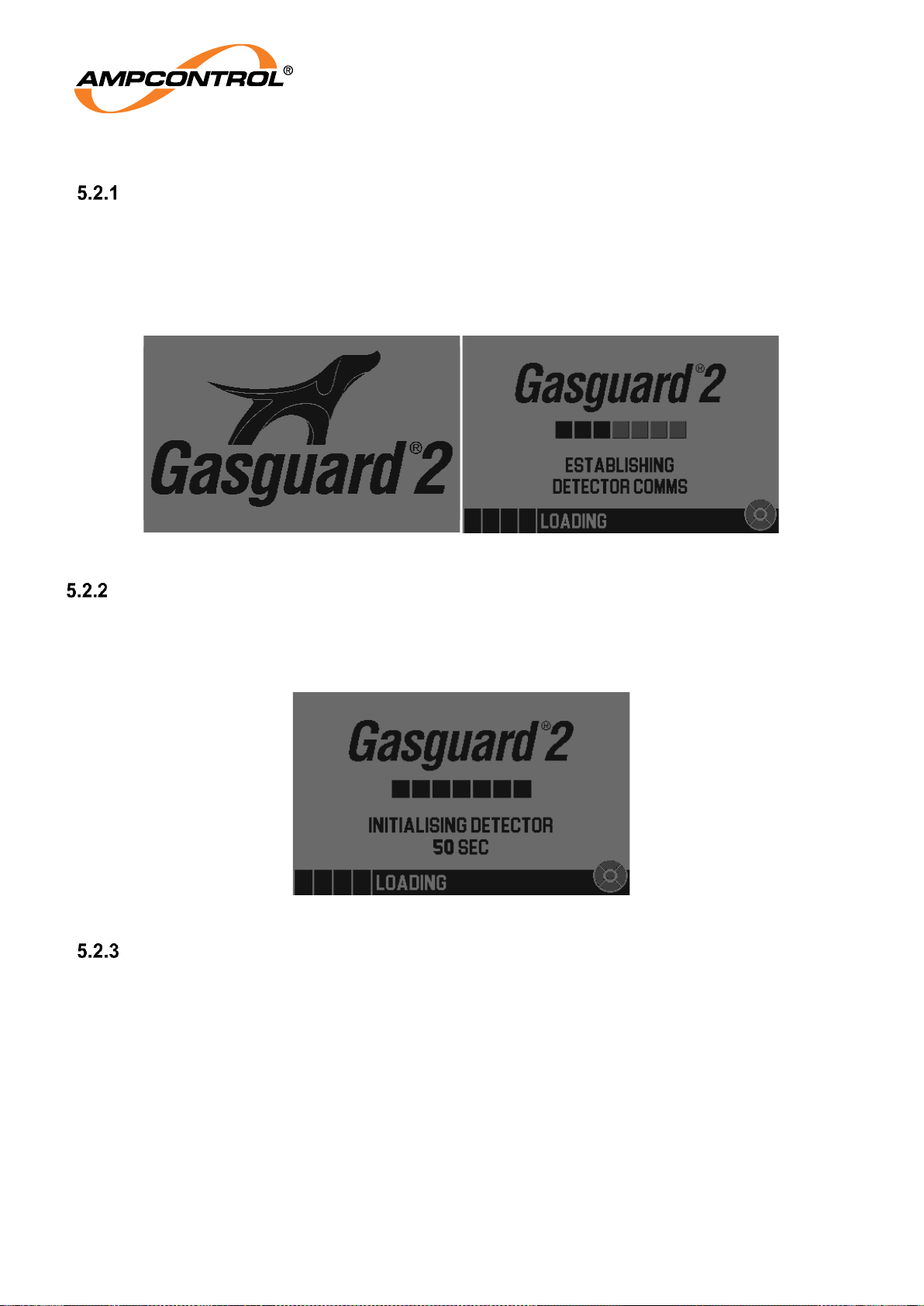
After a short delay, the Gasguard 2 title screen will be displayed as depicted on the left of Figure 26.
Whilst the GG2 title screen is shown (approx. 6s) the detector is powered on and the communications
protocols will be initialised. GG2 displays have a power-up slot assigned to them based on the serial
number; there are 50 slots of 100ms each. This feature reduces the power-up impact on a power supply
with multiple devices connected. After this, the display will then attempt to establish communications with
an attached GG2 Detector (right of Figure 26).
Figure 26: Title Screen (left) & Establishing GG2 Detector Communications (right)
GG2 Detector initialisation
Once the display has made a successful connection with the GG2 Detector the initialisation period of 60s
will begin. During the initialisation period, the screen controls are locked and the gas reading is not
displayed. The countdown timer shown on this screen may take a few seconds to appear due to the time
required to initialise communications with the detector.
Figure 27 - Initialisation Screen
GG2 Detector warmup
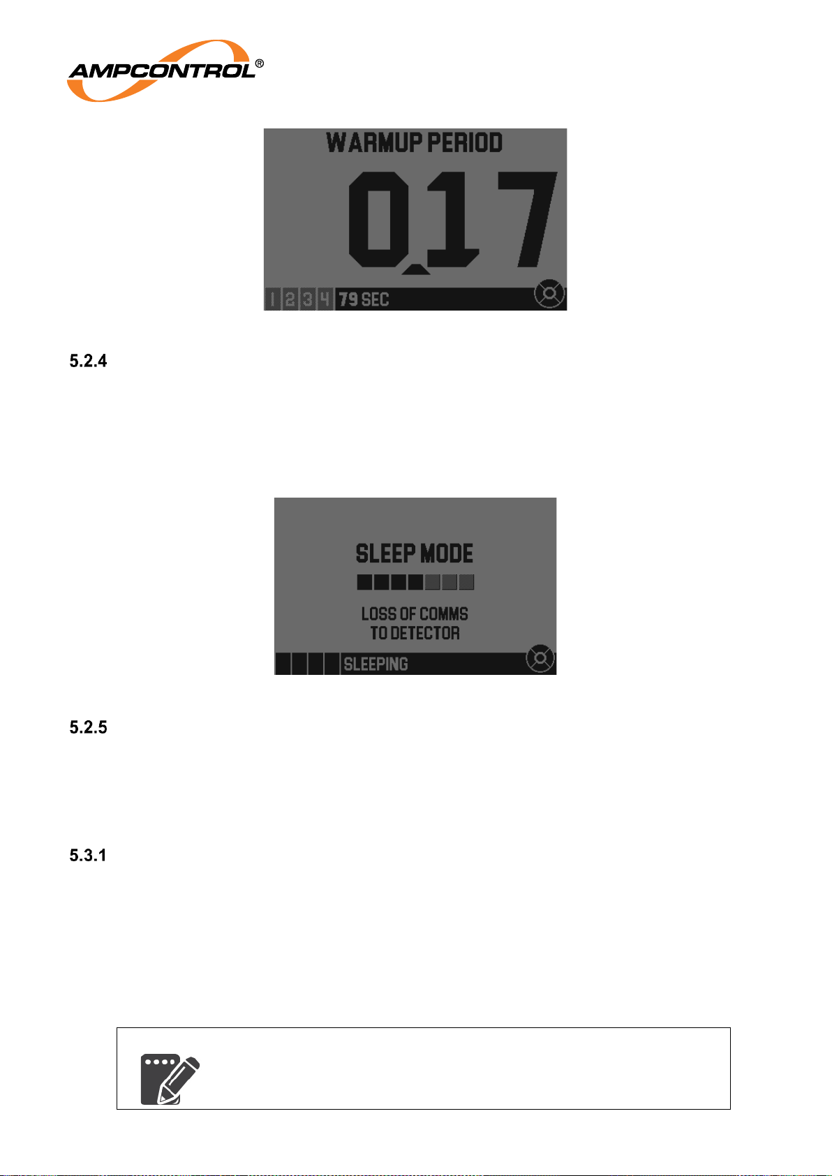
On power-up, any attached GG2 Detector will take some time to warm up, known as the warmup period.
During the warmup period, the GG2 Detectors do not provide accurate measurements. Each GG2
Detector type has its own warmup period, which is documented in the respective manual/datasheet. The
current gas reading will flash on the screen (1s on 0.5s off) while the home screen is in warm-up mode.
The behaviour of the external interfaces during the warmup period is specified in the relevant sections.
During the warm-up period, the Calibration menu is inaccessible.
In cases where the warmup period is equal to or less than the initialisation period (60s) the home screen
in warmup mode will not show as the warm-up time may have already elapsed. The warmup timer may
take a few seconds to appear.
Page 35
Ampcontrol Pty Ltd – ABN 28 000 915 542
GG2 DISPLAY USER MANUAL
GG2B023
Version 5 – NOVEMBER/2020
Uncontrolled Copy - Refer to Ampcontrol Website for Latest Version
Page 35 of 62
APPROVED FOR EXTERNAL DISTRIBUTION
– PROPERTY OF AMPCONTROL PTY LTD
– NOT TO BE REPRODUCED IN PART
Figure 28 - The Home Screen when in warmup
Sleep Mode
When the display is in sleep mode (as shown in Figure 29), power is not supplied to the detector port.
Sleep mode or detector isolation is a safe state for connection/disconnection of detectors or whenever
the detector port must be exposed. Sleep mode can normally only be entered by powering up the display
without a detector attached.
By powering up the display without a detector attached, the display will first attempt to communicate with
a detector and must therefore apply power, refer to Section 5.2.1.
Figure 29: Display Sleep Mode
Detector Isolation
Detector isolation only differs from sleep mode in how it is triggered and what is displayed on the screen.
Detector isolation is an intentional state and is entered when disconnecting a detector, refer to Section
5.3.2.
5.3 Connecting and Disconnecting a GG2 Detector
Connecting a GG2 Detector
The following steps detail connecting a detector to the display. Refer to Section 4.4.3 for more
information.
1. Ensure that the device is Isolated or in Sleep Mode, refer to Section 5.2.4 and Section 5.2.5.
2. Attach the new detector to the display or extension cable and secure the clip retainer by pushing
it fully rearwards, the pull ring should be in-line with the detector housing.
3. Take the device out of sleep mode by pressing any of the magnetic segments.
4. The display will attempt to communicate with the new detector (refer to Figure 26).
NOTE
The “Establishing Detector Comms” screen may only appear for a brief
period.
Page 36
Ampcontrol Pty Ltd – ABN 28 000 915 542
GG2 DISPLAY USER MANUAL
GG2B023
Version 5 – NOVEMBER/2020
Uncontrolled Copy - Refer to Ampcontrol Website for Latest Version
Page 36 of 62
APPROVED FOR EXTERNAL DISTRIBUTION
– PROPERTY OF AMPCONTROL PTY LTD
– NOT TO BE REPRODUCED IN PART
5. At this stage the display will either;
a. Show the detector warmup screen, please see 5.2.2, or
b. Show the different gas sensor warning, please see 5.3.1.1
5.3.1.1 Connection of the First Detector
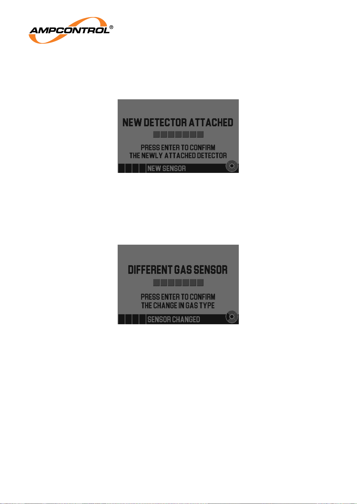
Figure 30: Connecting a Detector for the first time
A special warning screen is displayed when the first detector is connected to the system, refer to Figure
30. After acknowledging this screen by pressing the centre magnetic button, the display will either:
Begin the detector image update process, please see Section 5.3.1.4, or
Show the detector warmup screen, please see Section 5.2.2.
5.3.1.2 Changing Gas Sensor Type
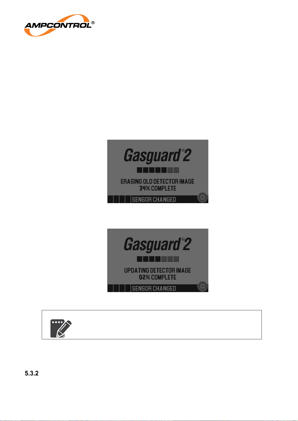
Figure 31: Different Gas Sensor Warning
A warning screen is displayed when the detector type is changed. This is to prevent accidental detector
type changes. A gas sensor type change results in the loss of all gas specific information from the
display, including:
Setpoints
Healthy region setting
Hysteresis setting
Last response test target
In addition, the data listed under Section 5.3.1.3 is removed.
After acknowledging this screen by pressing the centre magnetic button, the display will either:
Begin the detector image update process, refer to Section 5.3.1.4, or
Show the detector warmup screen, refer to Section 5.2.2.
Page 37
Ampcontrol Pty Ltd – ABN 28 000 915 542
GG2 DISPLAY USER MANUAL
GG2B023
Version 5 – NOVEMBER/2020
Uncontrolled Copy - Refer to Ampcontrol Website for Latest Version
Page 37 of 62
APPROVED FOR EXTERNAL DISTRIBUTION
– PROPERTY OF AMPCONTROL PTY LTD
– NOT TO BE REPRODUCED IN PART
5.3.1.3 Replacement of Detector (with same type)
On replacement of the detector (with another detector of the same type), several pieces of information
are removed from the system, namely:
Last max and min (peak) values and their timestamps
Linearity test results
There is no visual indication of this process.
5.3.1.4 Detector Image Update
Each gas detector contains a detector image that describes the functionality of the display. In the case
that the image on the detector is different to the one loaded into the display, the new image will be
downloaded.
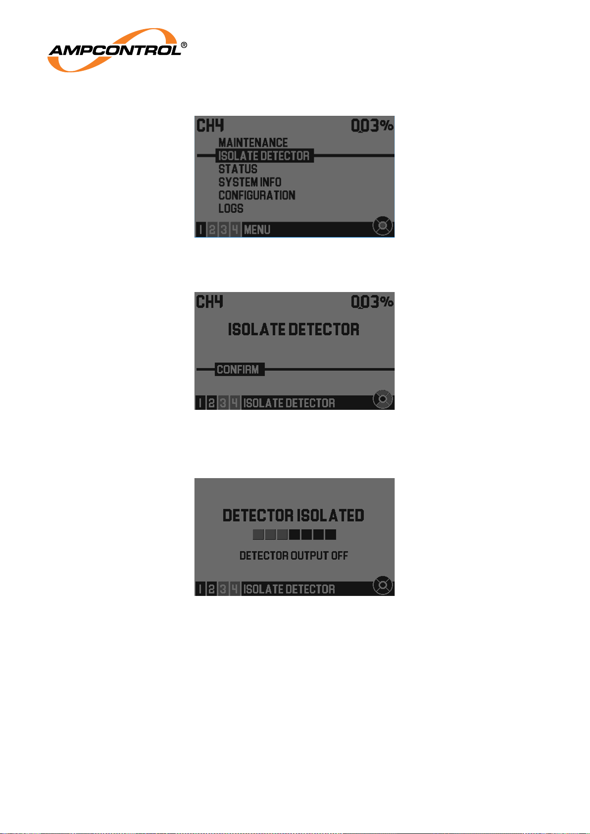
1. Flash erase - The previous image is erased from the display
Figure 32: Erasing the Old Detector Image
2. New image is loaded from the detector.
Figure 33: Updating the Detector Image
NOTE
This process can take up to 5 minutes.
3. On completion of the process the display should show the detector warmup screen (Figure 28) or
the home screen (Figure 15), depending on the warmup duration.
Disconnecting a Detector
The process for disconnecting a detector is as follows:
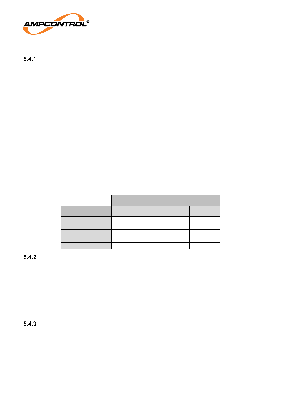
1. From the home screen, access the menu by pressing any button.
Page 38
Ampcontrol Pty Ltd – ABN 28 000 915 542
GG2 DISPLAY USER MANUAL
GG2B023
Version 5 – NOVEMBER/2020
Uncontrolled Copy - Refer to Ampcontrol Website for Latest Version
Page 38 of 62
APPROVED FOR EXTERNAL DISTRIBUTION
– PROPERTY OF AMPCONTROL PTY LTD
– NOT TO BE REPRODUCED IN PART
2. Navigate down to “ISOLATE DETECTOR”.
Figure 34: Isolate Detector
3. Press right to access the “ISOLATE DETECTOR” screen.
Figure 35: Isolate Detector Confirmation
4. Press enter to confirm. The text “DETECTOR ISOLATED” will display. Once this message is
on the display, the detector is safe to remove. The detector port is unpowered.
Figure 36: Detector Isolated
5. Whilst preventing the detector from falling, pull the ring attached to the locking plate away
from the display passing the two friction points. The detector can now be removed, refer to
Section 4.4.3 for more information.
Page 39
Ampcontrol Pty Ltd – ABN 28 000 915 542
GG2 DISPLAY USER MANUAL
GG2B023
Version 5 – NOVEMBER/2020
Uncontrolled Copy - Refer to Ampcontrol Website for Latest Version
Page 39 of 62
APPROVED FOR EXTERNAL DISTRIBUTION
– PROPERTY OF AMPCONTROL PTY LTD
– NOT TO BE REPRODUCED IN PART
5.4 External Interfaces
Gas Reading Units
As the protocols Modbus and iMAC are both limited to 16bit wide data registers, a system has been
used to encode the current gas reading of the device. The readings are transmitted in units of ‘permyriad
of full-scale’. A permyriad is 1/10000 (one ten thousandth) and can be denoted with a ‱ symbol. The
relationship between the real world units (e.g. PPM, %) and the permyriad is as follows:
Where:
=
gas zero value (i.e. 0% v/v)
=
gas span value (i.e. 5% v/v)
=
transmitted permyriad value (i.e. 123 ‱)
=
Real World Gas Value (i.e. 1.25% v/v)
These permyriad values therefore correspond to different gas concentrations on different detectors.
Some example values are calculated in the following table.
Table 6: Example of Permyriad to Gas Concentration Conversion
Gas Range and Units
Permyriad (‱)
0-5% v/v
0-100% v/v
0-10 ppm
-100 ‱
-0.05% v/v
-1% v/v
-0.1 ppm
0 ‱
0% v/v
0% v/v
0 ppm
5000 ‱
2.5% v/v
50% v/v
5 ppm
10000 ‱
5% v/v
100% v/v
10 ppm
10100 ‱
5.05% v/v
101% v/v
10.1 ppm
Protocol Selection
Before a protocol can be configured it must first be selected as the active protocol. Protocol selection
must be done via the “PROTOCOL SELECT” screen in the configuration menu, refer to Section 5.3.2.
The options are:
IMAC
MODBUS, or
NONE
For general guidance on editing these options, please refer to Section 5.1.2.2.
Modbus
5.4.3.1 Configuration
After selecting the Modbus protocol, it may be configured. Protocol configuration must be done via the
“PROTOCOL CONFIG” screen in the configuration menu. Within this menu, there is a single option SETTINGS. For general guidance on editing options, please refer to Section 5.1.2.2.
Page 40
Ampcontrol Pty Ltd – ABN 28 000 915 542
GG2 DISPLAY USER MANUAL
GG2B023
Version 5 – NOVEMBER/2020
Uncontrolled Copy - Refer to Ampcontrol Website for Latest Version
Page 40 of 62
APPROVED FOR EXTERNAL DISTRIBUTION
– PROPERTY OF AMPCONTROL PTY LTD
– NOT TO BE REPRODUCED IN PART
Table 7: Modbus - Protocol Configuration - Settings
Field Name
Value
ADDRESS
Specifies the Modbus address for the system.
Validity: 1-247
PARITY
Specifies the parity setting for Modbus. Options: EVEN, NONE
or ODD
BAUD
Specifies the Baud Rate of the RS485 bus.
Options: 19200, 9600, 38400 or 115200
STOP BITS
Specifies the number of stop bits.
Options: 1 or 2
POWER MODE
Options: HIGH or LOW
*Power Mode can selected between 5V logic (HIGH) and 3.3V logic (LOW).
LOW power mode will sightly reduce current consumption and should only be connected to compatible
logic devices over short cables.
NOTE
LOW power mode should only be connected to compatible logic
devices over short cables.
iMAC
5.4.4.1 Configuration
After selecting the iMAC protocol, it may be configured. Protocol configuration must be done via the
“PROTOCOL CONFIG” screen in the configuration menu. Within this menu, there are two screens,
ADDRESSES and GENERAL. For general guidance on editing options, please refer to Section 5.1.2.2.
The ADDRESSES screen may be used to configure data addresses on the iMAC.
Table 8: iMAC - Protocol Configuration - Addresses
Field Name
Value
STATUS
Specifies the iMAC address for system status information.
Validity: 0-255.
ANALOGUE
Specifies the iMAC address for analogue (4-20mA output)
information. Validity: 0-255.
POWER SUPPLY
Specifies the iMAC address for system power supply
information. Validity: 0-255.
SYS CLOCK
Specifies the iMAC address for system clock information.
Validity: 0-255.
CAT RESET
Specifies the iMAC address for catalytic reset command.
Validity: 0-255.
BYPASS
Specifies the iMAC address for system bypass command.
Validity: 0-255.
The GENERAL screen may be used to configure the following:
Page 41
Ampcontrol Pty Ltd – ABN 28 000 915 542
GG2 DISPLAY USER MANUAL
GG2B023
Version 5 – NOVEMBER/2020
Uncontrolled Copy - Refer to Ampcontrol Website for Latest Version
Page 41 of 62
APPROVED FOR EXTERNAL DISTRIBUTION
– PROPERTY OF AMPCONTROL PTY LTD
– NOT TO BE REPRODUCED IN PART
Table 9: iMAC - Protocol Configuration - General
Field Name
Value
VOLTAGE
(WARN)
Specifies the power supply warning voltage. Once the supply
voltage to the display drops below this value, the supply voltage
warning bit is set. Validity: 0-24V.
VOLTAGE
(ALARM)
Specifies the iMAC address for analogue (4-20mA output)
information. Once the supply voltage to the display drops below
this value, the supply voltage alarm bit is set. Validity: 0-24V.
ANALOG EXC
TRG
Specifies the setting for the analogue exception trigger. The
setting is the percentage difference between successive
analogue sample values that will cause an exception scan,
measurements are taken at 1Hz. Validity: 0-99.0.
4-20mA
The GG2 Display can drive a 4-20mA loop current. The operation of the 4-20mA loop is independent of
the other communications (iMAC and Modbus).
5.4.5.1 Behaviour
The 4-20mA output is being monitored by the GG2 Display to ensure that; the desired output is being
driven and that the full range of outputs should be able to be driven. In cases of excessive loop
impedance, a device fault will occur. The estimated 4-20mA loop impedance can be seen on the
“SYSTEM INFO” screens (Section 5.6.2).
5.4.5.2 Connection
The 4-20mA output should be connected from the 4-20mA out pin through the measurement device back
to the ground pin of the system interface connector.
5.4.5.3 Settings
Activation of the 4-20mA output is done from the “4-20mA SETTINGS” screen, refer to Section 5.1.2.
Table 10: 4-20mA Settings
Field Name
Value
ACTIVATION
Options: TRUE or FALSE. Specifies if the 4-20mA loop is
powered
WARMUP/FAULT
Options: HIGH or LOW. Specifies whether the warmup/fault
range is high or low. I.e.
LOW: warmup = 3mA, fault = 2mA.
HIGH: warmup 21mA, fault = 22mA.
5.4.5.4 Calibration
Before the start of calibration, if the GG2 Display has spent considerable time at low or elevated
temperatures, please allow the device to stabilise to room temperature in powered-up operational (no
fault) state for 24 hours before beginning calibration.
If the GG2 Display has not experienced exposure to temperature extremes the apparatus should be left
in a powered-up operational (no fault) state for one hour before beginning calibration.
Calibration of the 4-20mA output should be completed in line with regulatory and operational
requirements.
Page 42
Ampcontrol Pty Ltd – ABN 28 000 915 542
GG2 DISPLAY USER MANUAL
GG2B023
Version 5 – NOVEMBER/2020
Uncontrolled Copy - Refer to Ampcontrol Website for Latest Version
Page 42 of 62
APPROVED FOR EXTERNAL DISTRIBUTION
– PROPERTY OF AMPCONTROL PTY LTD
– NOT TO BE REPRODUCED IN PART
Please note that the 4-20mA calibration procedures are similar to the telemetry test and all outputs of the
device will be forced to zero or full-scale.
CAUTION!
The 4-20mA calibrations may trigger alarms and setpoint flags.
The calibration procedure calibrates each of the outputs independently. The calibration procedure should
be completed as follows:
1. Connect the 4-20mA loop to the NATA calibrated current measurement device and ensure that
the 4-20mA output is enabled (see 5.4.5.3). If the device is working normally, the measurement
should be between approximately 2 and 22mA.
2. Access the “4MA CALIBRATION” or “20MA CALIBRATION” screen; refer to Section 5.1.2. The
notice below will be displayed for a few seconds.
Figure 37: Calibration Notice (left) & 4mA Calibration (right)
3. The calibration measurement input screen will appear and the 4-20mA output will be forced to
what the device expects to be 4mA (or 20mA).
NOTE
In this example the “SETPOINT FLAG SET” status is present, as the
device is at 0% gas which is below setpoint 1.
4. Take the measurement from the NATA calibrated device and enter that measurement into the
device. Section 5.1.2.2 provides further guidance on editing values. Once the desired value has
been entered, press the centre segment of the keypad.
5. The saving changes screen will be shown and the calibration stage is complete.
6. It is recommended that, following a pair of calibrations (4mA and 20mA), a telemetry test is
performed to verify that the output varies as intended.
5.5 Gas Alarm and Setpoint Configuration
The GG2 Display is capable of comparing the current gas measurement against predefined setpoints.
These setpoints, coupled with a user defined healthy region, determine how setpoint flags may be set
and cleared. This system allows for a large amount of flexibility. The alarm LED indicator (red) on the
GG2 Display is driven by the current health status, when the current gas reading doesn’t lie within the
Page 43
Ampcontrol Pty Ltd – ABN 28 000 915 542
GG2 DISPLAY USER MANUAL
GG2B023
Version 5 – NOVEMBER/2020
Uncontrolled Copy - Refer to Ampcontrol Website for Latest Version
Page 43 of 62
APPROVED FOR EXTERNAL DISTRIBUTION
– PROPERTY OF AMPCONTROL PTY LTD
– NOT TO BE REPRODUCED IN PART
healthy region the alarm light will flash. Setpoints may be set to negative values to detect changes in the
measurement bias over time. Concepts in this section will be explained using examples.
Figure 38: Example Setpoint Configuration
The example in Figure 38 can be summarised as:
The gas reading is healthy when greater than SP1 (0%) and less than SP1 (1.25%)
Setpoint 3 is 2.5%
Looking at the example, we explain how the setpoint flags are set/cleared:
Setpoint flags are set when the gas reading moves away from the healthy region (positive or
negative gradient) and reaches a setpoint’s value. E.g. the SP3 flag will be set whenever the gas
reading is 2.5% or greater.
Setpoint flags are cleared when the gas reading moves toward the healthy region (positive or
negative gradient) and the setpoint’s value is crossed. E.g., the SP3 flag will be cleared
whenever the gas reading is less than 2.5%.
The corresponding settings in the GG2 Display for the example above are shown in Figure 39.
Figure 39: Configuration - Setpoints
Configuring Setpoints
The setpoints and healthy region setting can be configured on the “SETPOINTS” screen (refer to Section
5.1.2). Please refer to Section 5.1.2.2 for further information about changing options.
Table 11: Setpoint Configuration
Field Name
Value
SP-ONE
Numerical gas value between –span value and span value.
Setting must follow the rule that SP1 < SP2 < SP3.
SP-TWO
SP-THREE
Page 44
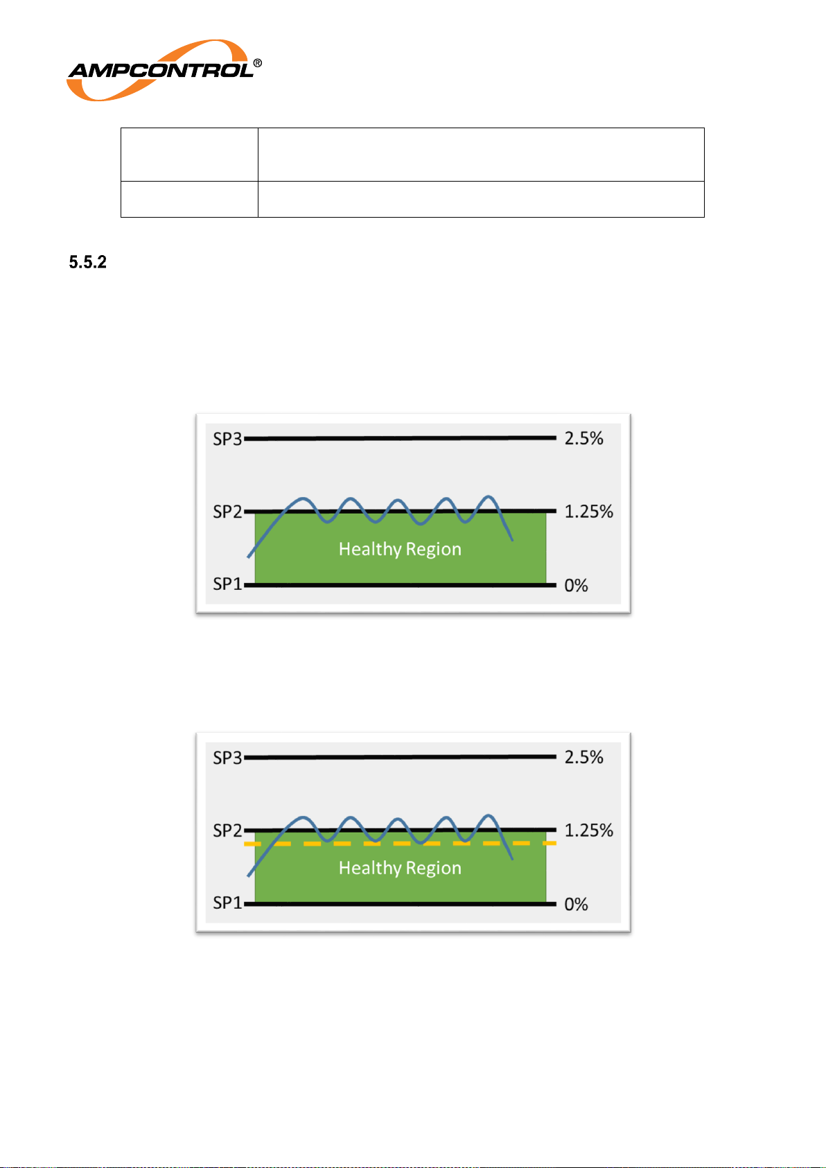
Ampcontrol Pty Ltd – ABN 28 000 915 542
GG2 DISPLAY USER MANUAL
GG2B023
Version 5 – NOVEMBER/2020
Uncontrolled Copy - Refer to Ampcontrol Website for Latest Version
Page 44 of 62
APPROVED FOR EXTERNAL DISTRIBUTION
– PROPERTY OF AMPCONTROL PTY LTD
– NOT TO BE REPRODUCED IN PART
HEALTHY
Healthy region setting. The smiley face indicates where the
healthy region lies relative to the setpoints. If the healthy region
is set to always, the hysteresis setting has no effect
HYSTERESIS
0-7.5%, increasing in 0.5% steps. See 5.5.2 for more
information about the hysteresis setting
Hysteresis Setting
The hysteresis setting can help to reduce the number of events which may occur when the gas reading
fluctuates about a setpoint. The hysteresis setting is particularly important in rapid response systems
such as iMAC where exception scans (priority data transmissions) are triggered by high criticality events.
Hysteresis solves this is by padding the setpoint value when clearing the setpoint flag. The example in
Figure 40 shows how the gas reading fluctuates about SP2 (1.25%). The first time the gas reading
reaches SP2, the SP2 flag is set. Then the value decreases and the SP2 flag is cleared. In the diagram
this will happen a further 4 times.
Figure 40: Multiple Triggering Scenario
Hysteresis enables a different value to clear the SP2 flag, i.e. therefore, the SP2 value sets the setpoint
flag but a lower value is needed to clear it. The orange line in Figure 41 represents the value needed to
clear the SP2 flag. This is called the hysteresis value.
Figure 41: Using Hysteresis Setting
In Figure 41, the value decreases below the SP2 value, but does not go smaller than the SP2 hysteresis
value and therefore the flag isn’t cleared. In this scenario there are only two transitions, one to set and
one at the end (on the right) to clear.
The hysteresis value is a percentage of the detectors span value, i.e. for a 0-5% v/v CH4 sensor a
hysteresis setting of 3% corresponds to 3% of 5% which is 0.15%. The hysteresis value must be
between 0% and 7.5% of the span value, with options increasing by 0.5% each step. The hysteresis will
Page 45
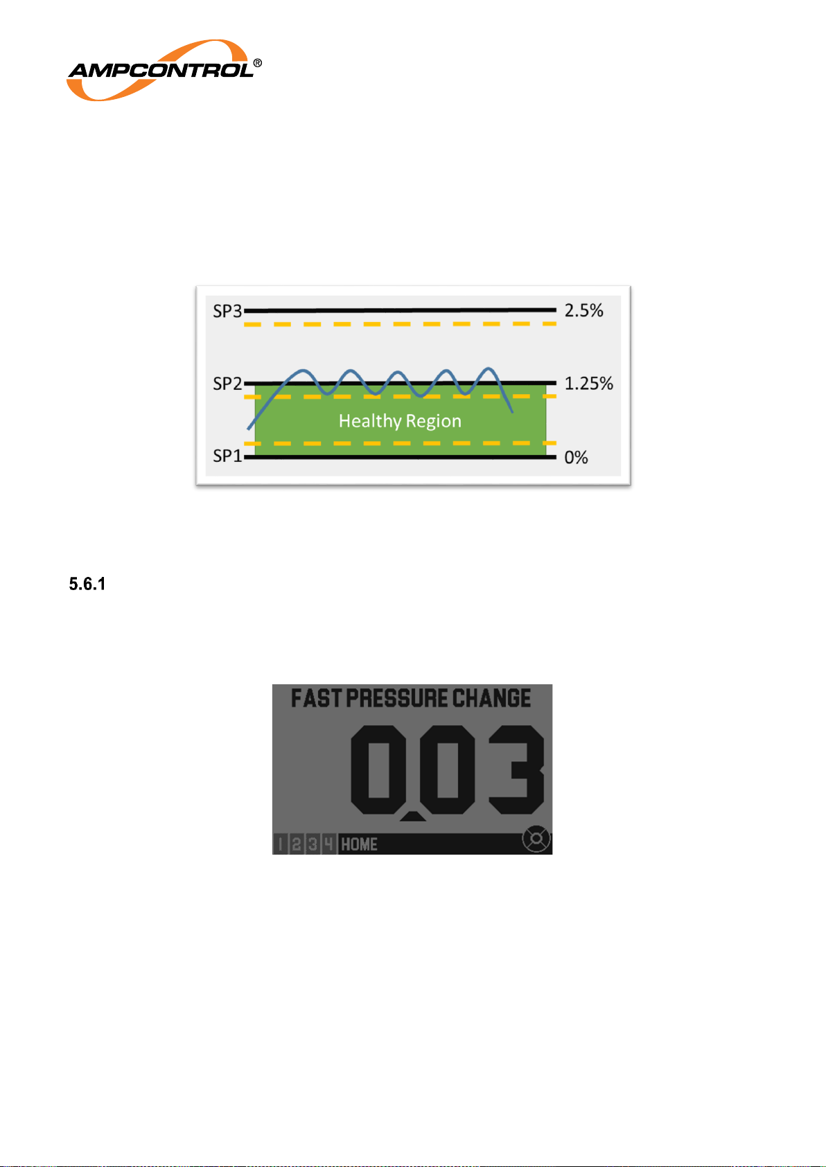
Ampcontrol Pty Ltd – ABN 28 000 915 542
GG2 DISPLAY USER MANUAL
GG2B023
Version 5 – NOVEMBER/2020
Uncontrolled Copy - Refer to Ampcontrol Website for Latest Version
Page 45 of 62
APPROVED FOR EXTERNAL DISTRIBUTION
– PROPERTY OF AMPCONTROL PTY LTD
– NOT TO BE REPRODUCED IN PART
act on all of the setpoints and the hysteresis threshold, i.e. the dotted yellow line (hysteresis value) will
always be closer to the healthy region (as shown in Figure 42). This can be summarised as:
Reaching the setpoint value when moving away from the healthy region will instantly set the
respective setpoint flag.
Crossing the setpoint value when moving toward the healthy region will not trigger a change.
Crossing the setpoints’ hysteresis value (dotted lines) when moving toward the healthy region will
clear the respective setpoint flag.
Figure 42: Hysteresis Value for each of the Setpoints
5.6 System Status and Information
Status
The status titles are shown on the screen whenever status flags are set. If multiple status flags are set,
the titles will change every five seconds. There may be a maximum of five status flags set in the system
at any time.
Figure 43: The HOME Screen with a Status Title "FAST PRESSURE CHANGE"
The STATUS screen can be accessed from the menu (Section 5.1.2) and provides more detail about the
current status flags. Once on the status screen, provided that there are multiple status flags, up and/or
down presses will change the display to the next/previous status.
As can be seen in Figure 44, the periodically changing status titles will be shown on ALL screens. The
status screen shows further information about each of the current status flags. The thick black line
separates the changing status titles and the content of the status screen. The descriptions will generally
provide some indication of which corrective actions should be taken. In the case of “LOW CELL
SENSITIVITY”, the device needs to be re-assessed by Ampcontrol as the detector element may have
reached the end of its normal operational lifespan.
Page 46
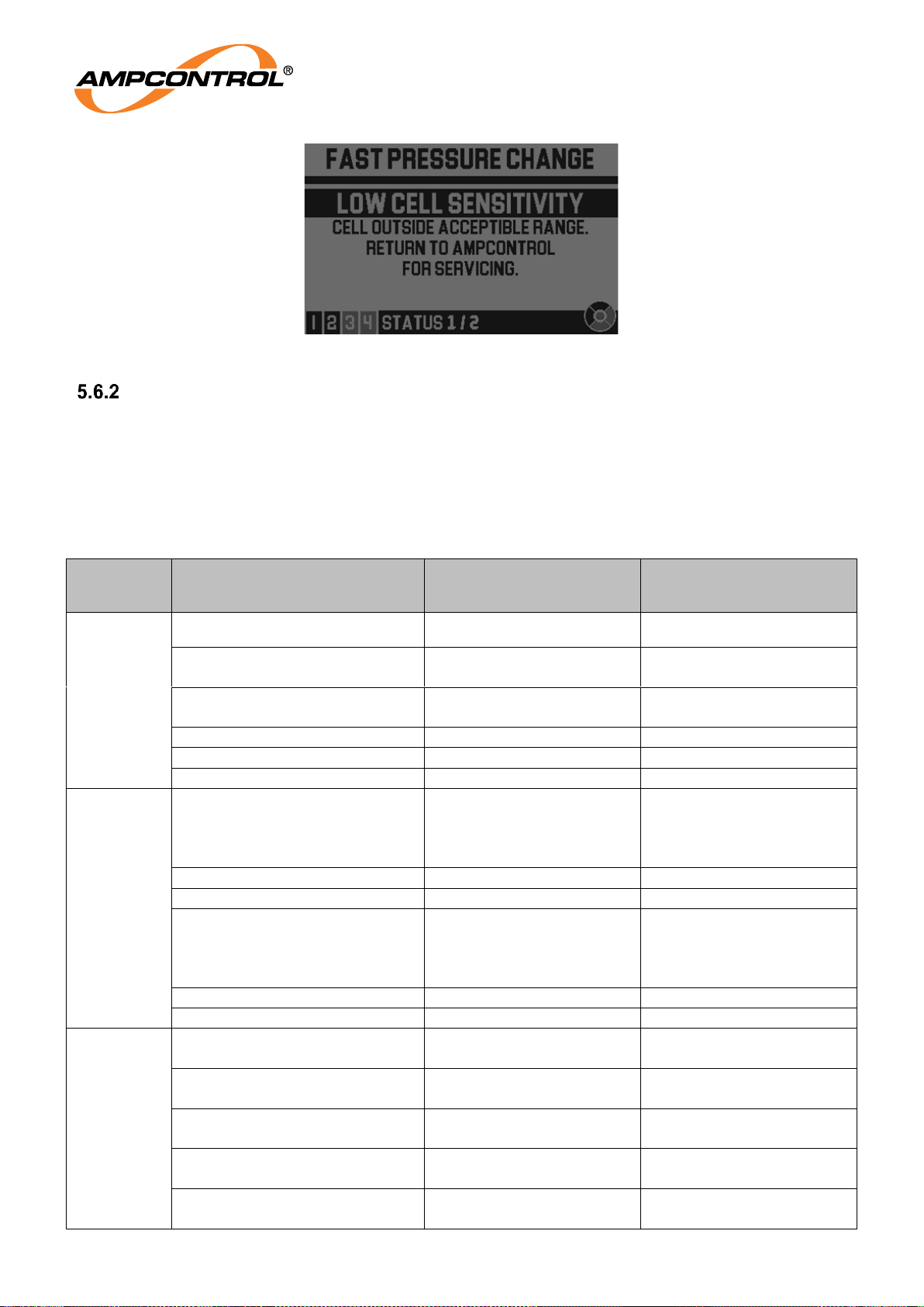
Ampcontrol Pty Ltd – ABN 28 000 915 542
GG2 DISPLAY USER MANUAL
GG2B023
Version 5 – NOVEMBER/2020
Uncontrolled Copy - Refer to Ampcontrol Website for Latest Version
Page 46 of 62
APPROVED FOR EXTERNAL DISTRIBUTION
– PROPERTY OF AMPCONTROL PTY LTD
– NOT TO BE REPRODUCED IN PART
Figure 44: The Status Screen - Low Cell Sensitivity
System Info
The “SYSTEM INFO” screens (refer to Section 5.1.2 for details on navigating the menu) provide a variety
of data about the system. The data contained on each of the screens is described in Table 12. Each of
the screens is a snapshot of the information when the screen is first entered. Press up/down on the
magnetic keypad to navigate through the screens.
Table 12: System Info Data Fields
Screen
number
Field name
Field description
Note
0
POWER SUPPLY
Power supply voltage (V)
4-20 MA STATE
4-20 mA output state
(ON/OFF)
4-20 MA OHMS
4-20 mA ohms. Estimated
loop resistance.
SETPOINT ONE
First setpoint
SETPOINT TWO
Second setpoint
SETPOINT THREE
Third setpoint
1
LPV – LOW
Last minimum value.
Lowest measured gas
value since last LPV
reset.
DATE
Date of occurrence
Using detector time
TIME
Time of occurrence
Using detector time
LPV – HIGH
Last maximum value.
Highest measured gas
value since last LPV
reset.
DATE
Date of occurrence
Using detector time
TIME
Time of occurrence
Using detector time
2
DETECTOR PRESSURE
Detector pressure
(Hectopascals, hPa)
Measurement is indicative
only
DETECTOR HUMIDITY
Detector relative humidity
(%)
Measurement is indicative
only
DETECTOR TEMP
Current temperature of
the detector element (°C)
DETECTOR SERIAL
Serial number of the
attached GG2 Detector
DETECTOR FW VER
Detector’s firmware
version
Page 47
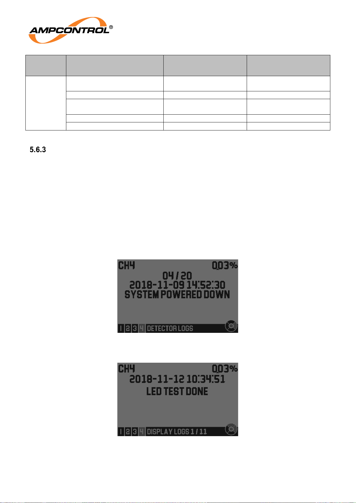
Ampcontrol Pty Ltd – ABN 28 000 915 542
GG2 DISPLAY USER MANUAL
GG2B023
Version 5 – NOVEMBER/2020
Uncontrolled Copy - Refer to Ampcontrol Website for Latest Version
Page 47 of 62
APPROVED FOR EXTERNAL DISTRIBUTION
– PROPERTY OF AMPCONTROL PTY LTD
– NOT TO BE REPRODUCED IN PART
Screen
number
Field name
Field description
Note
3
DISPLAY SERIAL
Serial number of the GG2
Display
DISPLAY FW VER
Display’s firmware version
DISPLAY APP VER
Version of the application
running on the display
DATE
Current detector date
TIME
Current detector time
Logs
The GG2 keeps logs to record significant events. There are screens for detector logs and display logs,
which may be used to view the recorded log entries.
5.6.3.1 Detector Logs
The detector logs can be accessed from the “DETECTOR LOGS” screen (Refer to Section 5.1.2 for
details on navigating the menu). The detector logs are loaded on request from the detector hence
“LOADING LOG..” is shown momentarily. To select an older/newer log press down/up respectively. The
detector will store at most the last 20 logs. An example log is shown in Figure 45. The log display
structure is as follows:
a. Log number (of 20)
b. Timestamp of the log, YYYY-MM-DD HH:MM:SS
c. Log text
Figure 45: Detector Log Example
5.6.3.2 Display Logs
Figure 46: Display Log Example
The display log screen is similar to the detector logs screen, and is titled “DISPLAY LOGS” (Refer to
Section 5.1.2 for details on navigating the menu). The log display structure is as follows:
Page 48
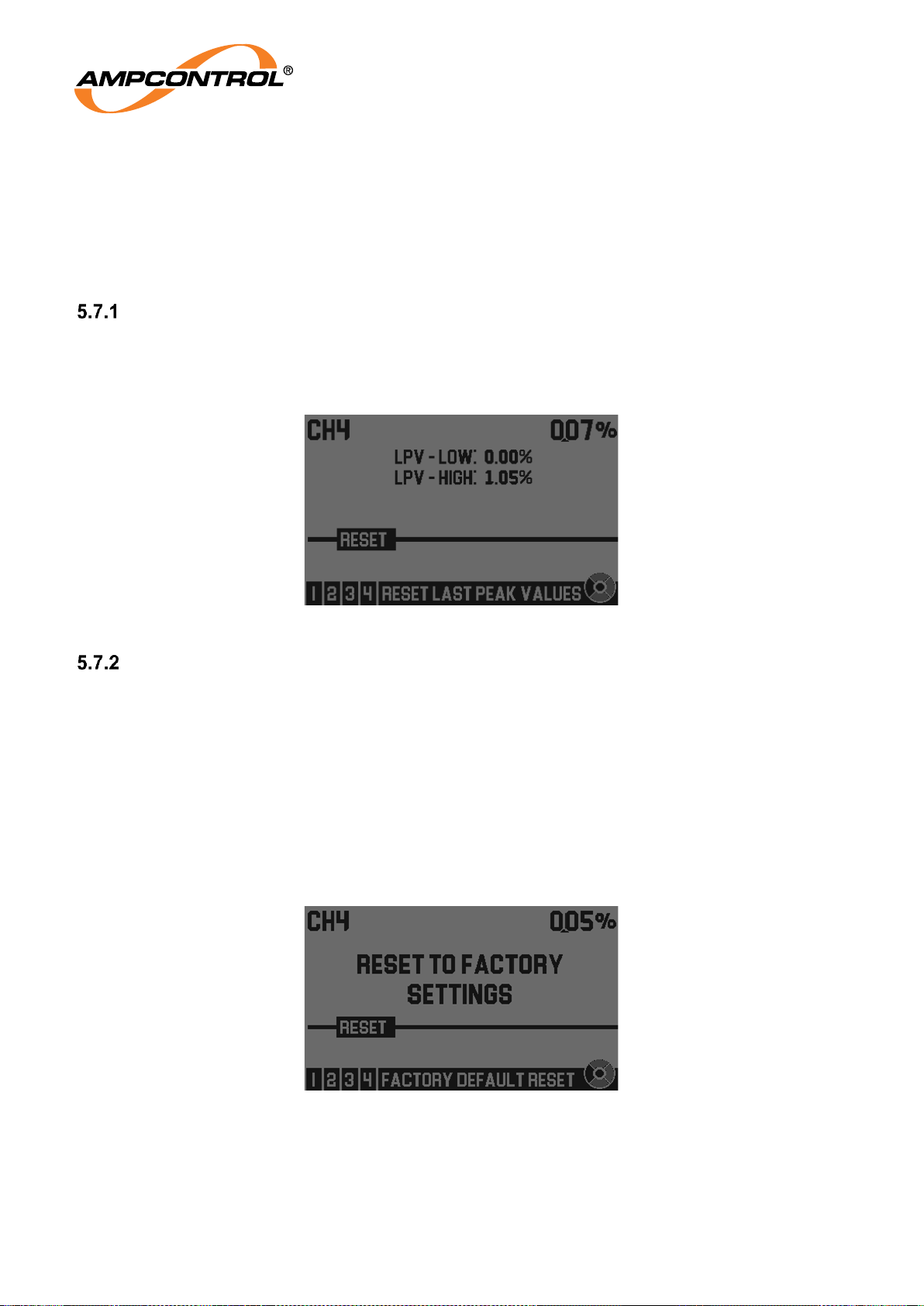
Ampcontrol Pty Ltd – ABN 28 000 915 542
GG2 DISPLAY USER MANUAL
GG2B023
Version 5 – NOVEMBER/2020
Uncontrolled Copy - Refer to Ampcontrol Website for Latest Version
Page 48 of 62
APPROVED FOR EXTERNAL DISTRIBUTION
– PROPERTY OF AMPCONTROL PTY LTD
– NOT TO BE REPRODUCED IN PART
a. Timestamp of the log YYYY-MM-DD HH:MM:SS
b. Log text
The display will store, at most, the 50 most recent logs. To select an older/newer log press down/up
respectively.
5.7 Display Maintenance
Peak Values Reset
Resetting of the recorded Last Peak Values (LPVs) can be done from the “RESET LAST PEAK
VALUES” screen. Refer to Section 5.1.2 for details on navigating the menu. On this screen, the current
LPVs are displayed. To reset the LPVs, press the centre segment of the magnetic keypad. The saving
changes screen will then be shown.
Figure 47: Reset Last Peak Values Screen
Factory Reset
The factory reset allows all settings to be cleared from the display, restoring it to an un-configured and
unused state with exception of the display logs and the display total runtime counter.
To perform a factory reset:
1. Navigate the menu to the “FACTORY DEFAULT RESET” screen. Refer to Section 5.1.2 for
details on navigating the menu.
2. The authorisation screen will be shown (refer to Section 5.1.2.1). Press the centre segment to
proceed.
3. The prompt “RESET TO FACTORY SETTINGS” will be shown. Press enter to proceed or left to
cancel.
Figure 48: Reset to Factory Defaults
4. The factory defaults saving screen will be shown. After this the system will reset.
Page 49
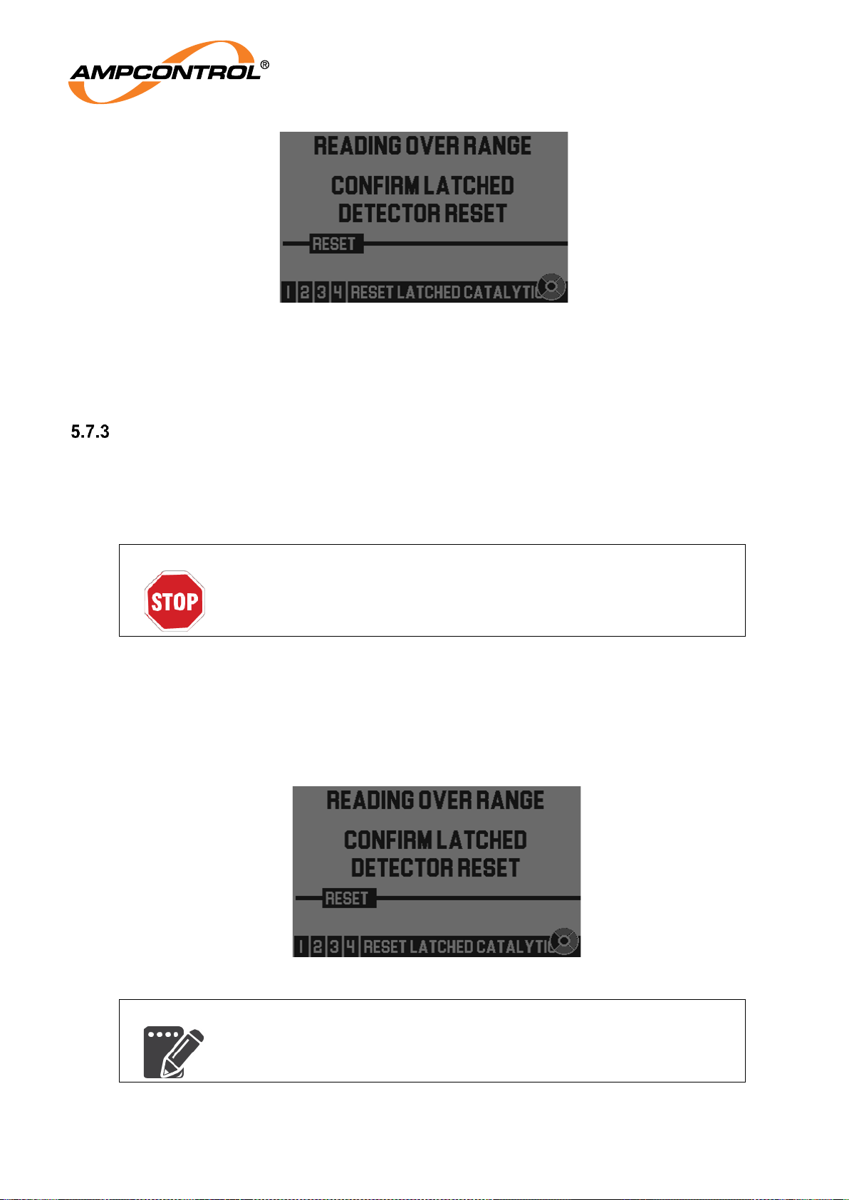
Ampcontrol Pty Ltd – ABN 28 000 915 542
GG2 DISPLAY USER MANUAL
GG2B023
Version 5 – NOVEMBER/2020
Uncontrolled Copy - Refer to Ampcontrol Website for Latest Version
Page 49 of 62
APPROVED FOR EXTERNAL DISTRIBUTION
– PROPERTY OF AMPCONTROL PTY LTD
– NOT TO BE REPRODUCED IN PART
Figure 49: Reverting to Factory Defaults
5. The new detector attached screen will be shown (see Section 5.3.1.1). Press centre to
acknowledge and proceed. The device may now be configured, refer to the GG2 RTGM Design
Installation and Maintenance Guide for more information.
Reset Latched Catalytic Detector
This section applies only to GG2 Displays with a catalytic detector attached. Methane gas concentrations
above the specified range may cause incorrect operation due to limitations of the catalytic bead. The
catalytic sensor will latch the reading to 5.25% v/v when the gas concentration exceeds 5.25% v/v and
will require the user to externally verify that the ambient gas concentration is within the measurement
range prior to resetting the latch.
WARNING!
Before resetting a catalytic detector latch, the actual methane
concentration at the detector must be confirmed safe; otherwise, the
device may show false readings.
To reset a latched catalytic from the GG2 Display HMI, perform the following steps:
1. Navigate to the “RESET LATCHED CATALYTIC” screen. Refer to Section 5.1.2 for details on
navigating the menu.
2. The authorisation screen will be shown (refer to Section 5.1.2.1). Press the centre segment to
proceed.
3. On the next screen, press centre to proceed and reset the catalytic latch or press left to cancel.
Figure 50: Catalytic latch reset
NOTE
There may be several status titles displayed which correspond to the
catalytic latch event. e.g. FULL SCALE LOCK, SETPOINT FLAG SET
and READING OVER RANGE.
Page 50

Ampcontrol Pty Ltd – ABN 28 000 915 542
GG2 DISPLAY USER MANUAL
GG2B023
Version 5 – NOVEMBER/2020
Uncontrolled Copy - Refer to Ampcontrol Website for Latest Version
Page 50 of 62
APPROVED FOR EXTERNAL DISTRIBUTION
– PROPERTY OF AMPCONTROL PTY LTD
– NOT TO BE REPRODUCED IN PART
4. The display will return to the menu without showing a confirmation. Once the latch is successfully
reset the gas reading should again reflect the actual gas value and the status flags should in turn
become unset.
LED Indicator Test
The LED indicator test can be used to verify the function of the three LED indicators on the GG2 Display.
The test sequence should be as follows:
1. One LED flashes several times, this repeats for the other LEDs, after which the cycle repeats.
This should happen approximately four times per LED.
2. The three LEDs should then flash together with increasing frequency until the end of the test.
3. On completion, the menu is displayed.
The behaviour of the LED test cannot be ensured when the fault/alarm LEDs are flashing due to alarm or
fault
Page 51

Ampcontrol Pty Ltd – ABN 28 000 915 542
GG2 DISPLAY USER MANUAL
GG2B023
Version 5 – NOVEMBER/2020
Uncontrolled Copy - Refer to Ampcontrol Website for Latest Version
Page 51 of 62
APPROVED FOR EXTERNAL DISTRIBUTION
– PROPERTY OF AMPCONTROL PTY LTD
– NOT TO BE REPRODUCED IN PART
6 SERVICE, MAINTENANCE & DISPOSAL
NOTE
If a GG2 Display Module is damaged a replacement may be obtained
from the manufacturer. See the Conditions of Safe Use for details.
Otherwise, there are no user serviceable parts. For repairs or
decommissioning, return to the manufacturer.
6.1 Equipment Service
A number of external system based checks should be completed on a regular basis. These ‘routine
inspections’ must be carried out by suitably trained people with knowledge of the GG2 Display and the
systems into which it is fitted. Routine inspections may take the form of either visual-only checks, or
visual and ‘hands-on’ checks.
Visual Only Inspections
A basic visual inspection focuses on looking at the installation for signs of physical damage, water or
dust ingress, and the condition of cables and labels. This type of inspection may involve opening
cabinets to gain access to the unit and other equipment. This level of inspection may also include
cleaning display windows that have become obscured by dirt.
Observations would typically be:
Check that equipment enclosures, cable trays, conduits, etc. are in good order with no physical
damage.
Check that sealed wall boxes are free from water and dust ingress internally. Door seals are in
good condition.
Check that connected cables are free from cuts, abrasions and obvious signs of damage. Cable
restraints are in good order and correctly fitted.
Check that labels on equipment, wall boxes and cables are present and in good condition
(especially certification labels).
Check that no modifications have been carried out to installed equipment.
Hands-On (Detailed) Inspections
A more detailed inspection would include all of the elements of a visual inspection, plus some checks
that cover the integrity of connections, fixtures and fittings.
In addition to basic visual observations, more detailed integrity checks would involve:
Verify that equipment housings, wall boxes and other mechanical fixtures are secured in place.
This includes terminal box lids, tightness of cable glands, integrity of wall-box mountings, security
of equipment fixing to walls/DIN rails etc.
Verify all electrical connections are secure with no loose screw terminals or DIN rail terminals not
fitted to rails etc.
Page 52
Ampcontrol Pty Ltd – ABN 28 000 915 542
GG2 DISPLAY USER MANUAL
GG2B023
Version 5 – NOVEMBER/2020
Uncontrolled Copy - Refer to Ampcontrol Website for Latest Version
Page 52 of 62
APPROVED FOR EXTERNAL DISTRIBUTION
– PROPERTY OF AMPCONTROL PTY LTD
– NOT TO BE REPRODUCED IN PART
6.2 Equipment Maintenance
Refer to the GG2 RTGM Design Installation and Maintenance Guide for an overview of calibration
and testing procedures.
WARNING!
Maintenance operations should not compromise safety in the area
being protected. Maintenance procedures should only be undertaken by
personnel trained in the operation, maintenance and repair of
flammable gas detection equipment.
Inadequate maintenance, incorrect zero and span adjustment are all causes for errors in gas detection. It
is important to remember that errors and failures in gas detection equipment or systems may not be selfevident. I.e. the DC offset (adjustment away from zero either positive or negative), if incorrectly adjusted,
will compromise the DC gain or span of the instrument resulting in the incorrect values/safety function of
the detector/safety system.
General Maintenance practices
The equipment or kit used for challenging or adjusting the Gasguard 2 instruments should be maintained
to a high standard and includes the following items:
Zero Gas, synthetic air and Nitrogen
Span Gas suitable for the instruments
Gasguard 2 Calibration mask
0.5l/m regulator
Tubing
NOTE
Each item shall be inspected prior to use.
Spares may deteriorate in storage owing to mishandling or age and should always be tested before use.
Periodic Maintenance
Periodic maintenance consists mainly of scheduled checks to ensure the instrument remains in
adjustment and gives the required response to the sampled gas. For recommended maintenance tasks
and schedules, refer to the AS/NZS 2290 series.
Page 53

Ampcontrol Pty Ltd – ABN 28 000 915 542
GG2 DISPLAY USER MANUAL
GG2B023
Version 5 – NOVEMBER/2020
Uncontrolled Copy - Refer to Ampcontrol Website for Latest Version
Page 53 of 62
APPROVED FOR EXTERNAL DISTRIBUTION
– PROPERTY OF AMPCONTROL PTY LTD
– NOT TO BE REPRODUCED IN PART
6.2.2.1 AS/NZS2290.3:2018 - Schedule of Tests
AS/NZS2290.3:2018 prescribes the maintenance requirements of Gas Detectors for Coal Mines.
Table 13: AS/NZS2290.3.2018 - Schedule of Inspection and Tests
Maintenance
Frequency
Fixed
AS/NZS
2290.3
Associated
Clause
Machine Mounted
AS/NZS
2290.3
Associated
Clause
Daily
External Inspection
4.2
External inspection
4.2
Weekly
N/A
N/A
Zero test
Span test
Response time test
4.3
4.4
4.5
Monthly
External inspection
Zero test
Span test
Response time test
4.2
4.3
4.4
4.5
Telemetry test
4.6
Six Monthly
Calibration
Telemetry test
Dynamic range test
4.7
4.6
4.8
Calibration
Dynamic range test
4.7
4.8
On relocation
External inspection
Zero test
Span test
Response time test
Telemetry test
Dynamic range test
4.2
4.3
4.4
4.5
4.6
4.8
External inspection
Zero test
Span test
Response time test
Telemetry test
Dynamic range test
4.2
4.3
4.4
4.5
4.6
4.8
On return to
service
Zero test
Span test
Response time test
Telemetry test
Dynamic range test
Confirm calibration is
current
4.3
4.4
4.5
4.6
4.8
1.3.4
Zero test
Span test
Response time test
Telemetry test
Dynamic range test
Confirm calibration is
current
4.3
4.4
4.5
4.6
4.8
1.3.4
Page 54
Ampcontrol Pty Ltd – ABN 28 000 915 542
GG2 DISPLAY USER MANUAL
GG2B023
Version 5 – NOVEMBER/2020
Uncontrolled Copy - Refer to Ampcontrol Website for Latest Version
Page 54 of 62
APPROVED FOR EXTERNAL DISTRIBUTION
– PROPERTY OF AMPCONTROL PTY LTD
– NOT TO BE REPRODUCED IN PART
Corrective Maintenance
During maintenance, it is vital to ensure that suitable procedures are followed to prevent any abnormal
sensor signal from unintentionally operating any fault, warning or alarm status indicator, or equipment
control function. Consult the relevant control unit manual for details as to how to do this.
There are no user serviceable parts. If a fault develops, the detector must be returned to an accredited
repair facility.
Table 14: Corrective Maintenance Checks
Fault
Checks
GG2 Detector will
not respond to
digital commands
a) Check that voltage and polarity applied to the instrument is correct.
b) Check the external interface is wired correctly to a compatible module.
c) Check for loose plug and terminal connections.
GG2 Detector
cannot be
Spanned or
Zeroed
a) Gas element has been damaged or is end of life, return to
manufacturer.
Measurement
range exceeded
a) Apply span gas and verify the result is within accuracy.
Device status
remains in warm-
up continuously
a) Check that voltage and polarity applied to the instrument is correct.
b) Turn the instrument off for >1 min before turning it back on.
c) Gas element has been damaged or is end of life, return to
manufacturer.
T90 Time
exceeded
a) Inspect and remove blockages from the filter cage.
b) Gas element has been damaged or is end of life, return to
manufacturer.
6.3 Disposal
ENVIRO
The electronic equipment discussed in this manual must not be
treated as general waste. By ensuring that this product is disposed of
correctly, you will be helping to prevent potentially negative
consequences for the environment, which could otherwise be caused
by incorrect waste handling of this product.
Page 55
Ampcontrol Pty Ltd – ABN 28 000 915 542
GG2 DISPLAY USER MANUAL
GG2B023
Version 5 – NOVEMBER/2020
Uncontrolled Copy - Refer to Ampcontrol Website for Latest Version
Page 55 of 62
APPROVED FOR EXTERNAL DISTRIBUTION
– PROPERTY OF AMPCONTROL PTY LTD
– NOT TO BE REPRODUCED IN PART
7 SPECIFICATIONS
7.1 GG2 Display
Electrical
Supply Voltage
10 - 16.5VDC
Max Power Consumption
12mA
Mechanical and Environment
Dimensions (H x W x D)
168mm x 90mm x 94mm
Weight
3kg
IP Rating
IP66
Housing Material
Cast Stainless Steel
Operating Temperature
-20°C to +40°C
Humidity Range
15% to 90% r.h. non-condensing
Pressure Range
±20kPa
Communications (iMAC L1)
Hardware interface
2 wire (+/-18VDC I.S.)
Line Speed
300 - 1000 baud
Bit protocol
iMAC proprietary
L1 Isolation
5.3kV RMS
L1 Line Loading (baud)
1mA (300 - 1000 baud)
Certification
IECEx
IECEx ExTC 18.0003X Issue No. 0
IECEx ITA 07.0017X Issue No. 2
Page 56

Ampcontrol Pty Ltd – ABN 28 000 915 542
GG2 DISPLAY USER MANUAL
GG2B023
Version 5 – NOVEMBER/2020
Uncontrolled Copy - Refer to Ampcontrol Website for Latest Version
Page 56 of 62
APPROVED FOR EXTERNAL DISTRIBUTION
– PROPERTY OF AMPCONTROL PTY LTD
– NOT TO BE REPRODUCED IN PART
8 EQUIPMENT LIST
NOTE
Customised gas panels and systems are also available as well as
sample draw panels. These can be designed specifically to your
gas sensing needs.
Refer to GG2B026 GG2 Monitoring Solution Technical Datasheet for
a detailed equipment list.
For more information call customer service on
1300 267 373
Page 57

Ampcontrol Pty Ltd – ABN 28 000 915 542
GG2 DISPLAY USER MANUAL
GG2B023
Version 5 – NOVEMBER/2020
Uncontrolled Copy - Refer to Ampcontrol Website for Latest Version
Page 57 of 62
APPROVED FOR EXTERNAL DISTRIBUTION
– PROPERTY OF AMPCONTROL PTY LTD
– NOT TO BE REPRODUCED IN PART
9 APPROVALS
9.1 IECEx ITA 07.0017X Issue No. 2
iMAC System:
The official controlled version of the certificate may be obtained online from the IECEx website
9.2 IECEx ExTC 18.0003X Issue No. 0
GG2 Display Module:
The official controlled version of the certificate may be obtained online from the IECEx website
The attached certificate below was current when this document was published but is to be considered an
uncontrolled version.
Page 58

Ampcontrol Pty Ltd – ABN 28 000 915 542
GG2 DISPLAY USER MANUAL
GG2B023
Version 5 – NOVEMBER/2020
Uncontrolled Copy - Refer to Ampcontrol Website for Latest Version
Page 58 of 62
APPROVED FOR EXTERNAL DISTRIBUTION
– PROPERTY OF AMPCONTROL PTY LTD
– NOT TO BE REPRODUCED IN PART
Page 59

Ampcontrol Pty Ltd – ABN 28 000 915 542
GG2 DISPLAY USER MANUAL
GG2B023
Version 5 – NOVEMBER/2020
Uncontrolled Copy - Refer to Ampcontrol Website for Latest Version
Page 59 of 62
APPROVED FOR EXTERNAL DISTRIBUTION
– PROPERTY OF AMPCONTROL PTY LTD
– NOT TO BE REPRODUCED IN PART
Page 60
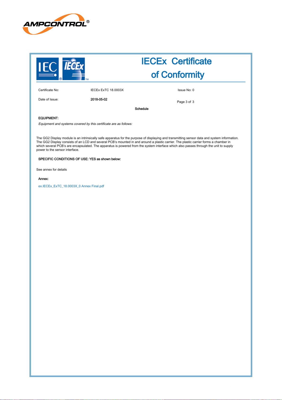
Ampcontrol Pty Ltd – ABN 28 000 915 542
GG2 DISPLAY USER MANUAL
GG2B023
Version 5 – NOVEMBER/2020
Uncontrolled Copy - Refer to Ampcontrol Website for Latest Version
Page 60 of 62
APPROVED FOR EXTERNAL DISTRIBUTION
– PROPERTY OF AMPCONTROL PTY LTD
– NOT TO BE REPRODUCED IN PART
Page 61
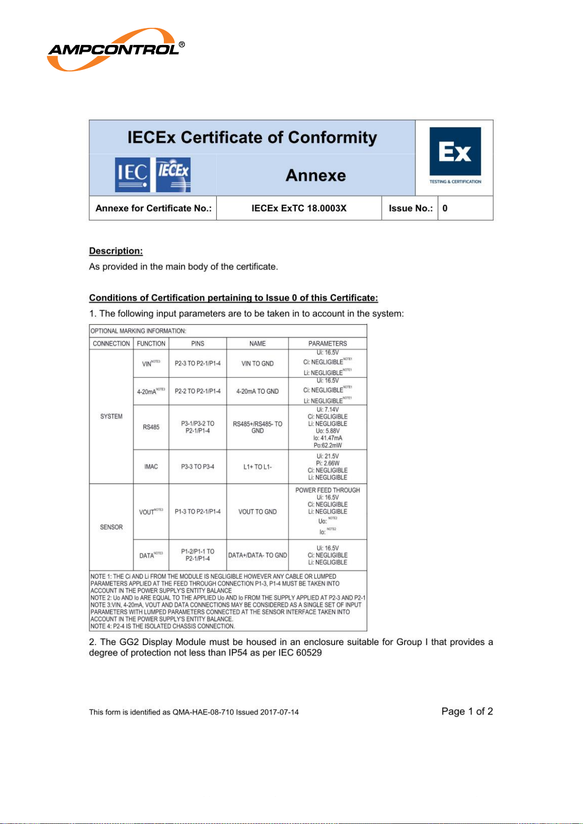
Ampcontrol Pty Ltd – ABN 28 000 915 542
GG2 DISPLAY USER MANUAL
GG2B023
Version 5 – NOVEMBER/2020
Uncontrolled Copy - Refer to Ampcontrol Website for Latest Version
Page 61 of 62
APPROVED FOR EXTERNAL DISTRIBUTION
– PROPERTY OF AMPCONTROL PTY LTD
– NOT TO BE REPRODUCED IN PART
Page 62
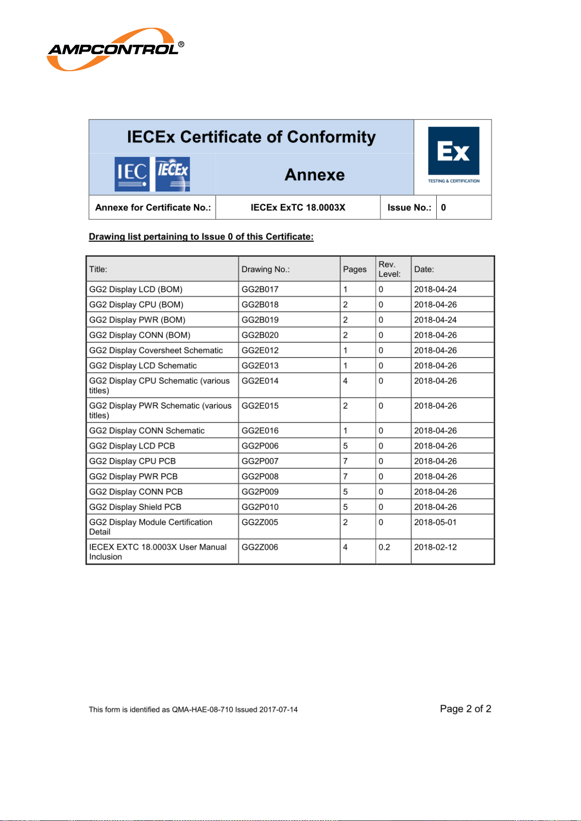
Ampcontrol Pty Ltd – ABN 28 000 915 542
GG2 DISPLAY USER MANUAL
GG2B023
Version 5 – NOVEMBER/2020
Uncontrolled Copy - Refer to Ampcontrol Website for Latest Version
Page 62 of 62
APPROVED FOR EXTERNAL DISTRIBUTION
– PROPERTY OF AMPCONTROL PTY LTD
– NOT TO BE REPRODUCED IN PART
 Loading...