

Page 1
Version: 4, October 2020
PN: 177870, 177871, 177872, 177873, 177874, 180733, 180734, 190998, 192855, 193071
Designed and manufactured in Australia by Ampcontrol Pty Ltd
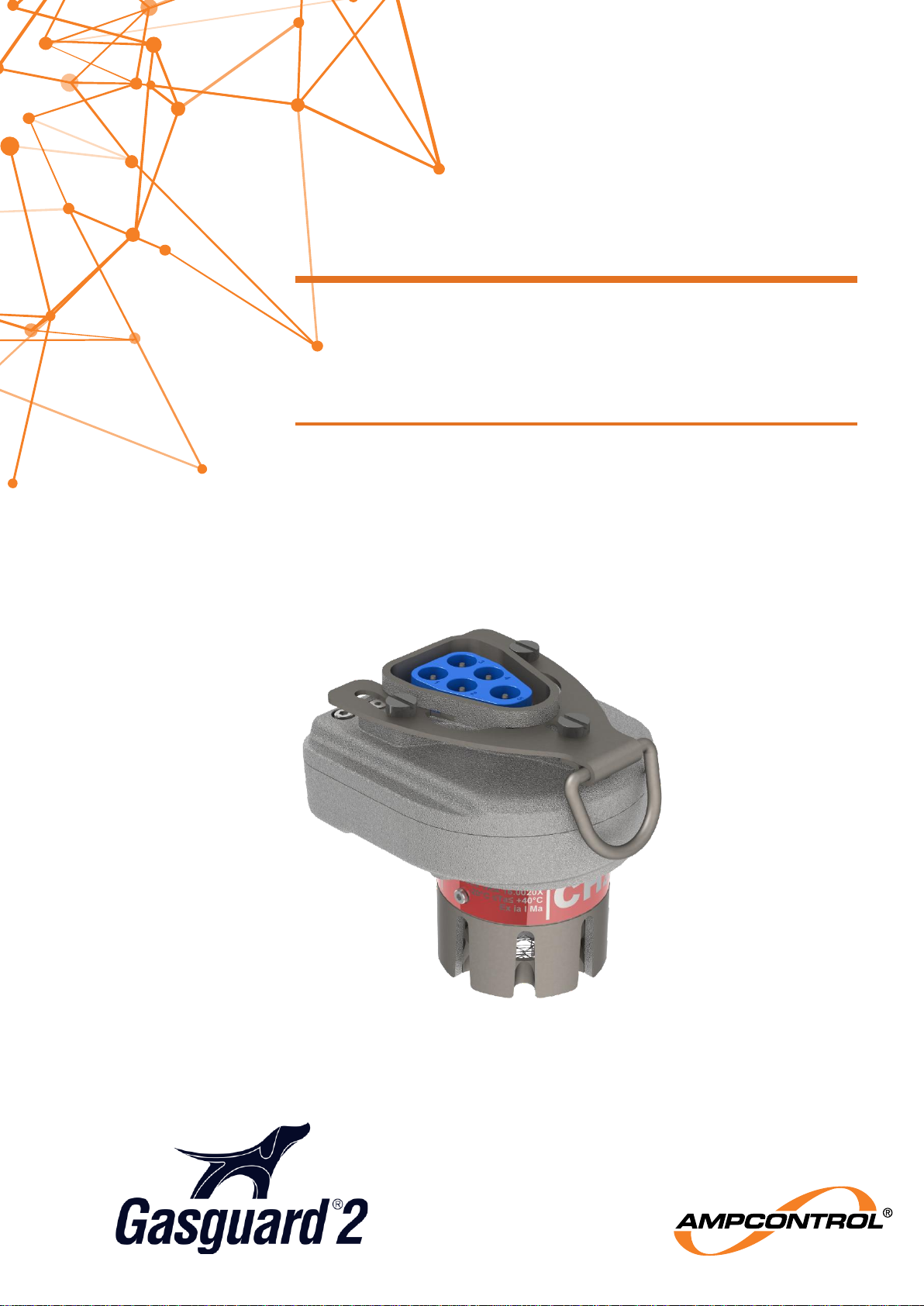
GG2 DETECTOR
CH4 / O2 / CO / CO2 / H2S SENSOR UNITS
User Manual
Page 2
Ampcontrol Pty Ltd – ABN 28 000 915 542
GG2 DETECTOR USER MANUAL
GG2B011
Version 4 – October/2020
Uncontrolled Copy - Refer to Ampcontrol Website for Latest Version
Page 2 of 40
APPROVED FOR EXTERNAL DISTRIBUTION
– PROPERTY OF AMPCONTROL PTY LTD
– NOT TO BE REPRODUCED IN PART
WARNING!
The warning symbol highlights a potential risk malfunction or loss of
performance
Please share these warnings with other operators.
CAUTION!
The caution symbol highlights a potential risk of damage to
equipment.
Please share these cautions with other operators.
NOTE
The note symbol highlights key information.
Please share these notes with other operators.
ENVIRO
The enviro (environmental) symbol highlights areas which may have an
impact on the surrounding fauna and/or flora.
Page 3

Ampcontrol Pty Ltd – ABN 28 000 915 542
GG2 DETECTOR USER MANUAL
GG2B011
Version 4 – October/2020
Uncontrolled Copy - Refer to Ampcontrol Website for Latest Version
Page 3 of 40
APPROVED FOR EXTERNAL DISTRIBUTION
– PROPERTY OF AMPCONTROL PTY LTD
– NOT TO BE REPRODUCED IN PART
Copyright Notice
The Ampcontrol GG2 Display described in this document is the property of AMPCONTROL PTY LTD. It
is furnished under a license agreement and is to be used only in accordance with the terms of the
agreement.
No part of the hardware or documentation may be reproduced, transmitted, transcribed, stored in any
retrieval system, or translated into any language or computer language, in any form or by any means,
without prior written permission of AMPCONTROL PTY LTD.
Disclaimer
While every effort has been made to assure the accuracy and clarity of this document, AMPCONTROL
PTY LTD assumes no liability resulting from any omissions in this document, or from misuse of the
information obtained herein. The information in this document has been carefully checked and is believed
to be entirely reliable with all of the necessary information included. AMPCONTROL PTY LTD reserves
the right to make changes to any products described herein to improve reliability, function, or design, and
reserves the right to revise this document and make changes from time to time in content hereof with no
obligation to notify any persons of revisions or changes. AMPCONTROL PTY LTD does not assume any
liability arising out of the application or any use of any product or circuit described herein; neither does it
convey license under its patent rights or the rights of others.
Before You Begin
Thank you for purchasing from the Ampcontrol GG2 range.
WARNING!
In the interests of safety and correct equipment operation, please
take the time to read and understand the content in this manual.
Ampcontrol Contact Details
7 Billbrooke Close, Cameron Park, NSW, 2285
P +61 1300 267 373 | F +61 2 4903 4888
EMAIL: [email protected]
WEB: ampcontrolgroup.com
Page 4

Ampcontrol Pty Ltd – ABN 28 000 915 542
GG2 DETECTOR USER MANUAL
GG2B011
Version 4 – October/2020
Uncontrolled Copy - Refer to Ampcontrol Website for Latest Version
Page 4 of 40
APPROVED FOR EXTERNAL DISTRIBUTION
– PROPERTY OF AMPCONTROL PTY LTD
– NOT TO BE REPRODUCED IN PART
TABLE OF CONTENTS
DEFINITIONS ...................................................................................................... 7
1 SAFETY AND OTHER WARNINGS .................................................................. 8
1.1 Safe Use of Equipment .............................................................................. 8
1.2 Supplementary Documentation .................................................................. 9
2 RECEIVING AND STORAGE .......................................................................... 10
2.1 Receiving ................................................................................................. 10
2.2 Inspection ................................................................................................ 10
2.3 Storage after Delivery .............................................................................. 10
2.4 Unpacking of Equipment .......................................................................... 10
3 PRODUCT OVERVIEW .................................................................................. 11
3.1 Overview .................................................................................................. 11
3.2 Key Features: .......................................................................................... 11
3.3 GG2 Display Module ................................................................................ 11
3.4 Markings .................................................................................................. 13
3.5 Electrochemical Sensors ......................................................................... 13
3.6 Catalytic Sensors ..................................................................................... 14
3.7 NDIR Sensors .......................................................................................... 16
3.8 Enclosure ................................................................................................. 16
3.9 Certification .............................................................................................. 18
4 INSTALLATION ............................................................................................... 19
4.1 General Warnings .................................................................................... 19
4.2 Mandatory Installation Practices .............................................................. 19
4.3 Installation Guidelines ................................ .............................................. 20
4.4 Conditions of Safe Use ............................................................................ 21
4.5 Mechanical Installation Information .......................................................... 22
4.6 Electrical Installation Information ............................................................. 22
5 COMMISSIONING AND CALIBRATION ......................................................... 24
5.1 Preliminary Checks .................................................................................. 24
5.2 Calibration ............................................................................................... 24
5.3 Calibration Troubleshooting ..................................................................... 24
6 SERVICE, MAINTENANCE & DISPOSAL ....................................................... 26
6.1 Equipment Service ................................................................................... 26
6.2 Equipment Maintenance .......................................................................... 26
6.3 Disposal ................................................................................................... 27
7 SPECIFICATIONS .......................................................................................... 28
7.1 Electrochemical O2 .................................................................................. 28
Page 5

Ampcontrol Pty Ltd – ABN 28 000 915 542
GG2 DETECTOR USER MANUAL
GG2B011
Version 4 – October/2020
Uncontrolled Copy - Refer to Ampcontrol Website for Latest Version
Page 5 of 40
APPROVED FOR EXTERNAL DISTRIBUTION
– PROPERTY OF AMPCONTROL PTY LTD
– NOT TO BE REPRODUCED IN PART
7.2 Electrochemical CO ................................................................................. 29
7.3 Electrochemical H2S ................................................................................ 30
7.4 NDIR CH4 ................................................................................................ 30
7.5 NDIR CO2 ................................................................................................ 32
7.6 Catalytic CH4 ........................................................................................... 33
8 EQUIPMENT LIST .......................................................................................... 34
9 APPROVALS .................................................................................................. 35
9.1 MDR 0001030 GD ................................................................................... 35
9.2 MDR 0001558 GD ................................................................................... 35
9.3 IECEx TRA 16.0020X .............................................................................. 35
Page 6

Ampcontrol Pty Ltd – ABN 28 000 915 542
GG2 DETECTOR USER MANUAL
GG2B011
Version 4 – October/2020
Uncontrolled Copy - Refer to Ampcontrol Website for Latest Version
Page 6 of 40
APPROVED FOR EXTERNAL DISTRIBUTION
– PROPERTY OF AMPCONTROL PTY LTD
– NOT TO BE REPRODUCED IN PART
TABLE OF FIGURES
Figure 1: GG2 Example Compatible Modules (iMAC Communication) ................................................... 12
Figure 2: GG2 Detector Overview ........................................................................................................... 12
Figure 3: GG2 Detector enclosure nominal dimensions (mm) ................................................................. 22
Figure 4: GG2 Detector Connector P1 Pin numbering ............................................................................ 23
TABLE OF TABLES
Table 1: Minimum Marking Information ................................................................................................... 13
Table 2: Optional Marking Information .................................................................................................... 13
Table 3: Poisoning of Sensors ................................................................................................................ 14
Table 4: Ingress Protection Rating .......................................................................................................... 17
Table 5: Gas Density Relative to Air ....................................................................................................... 21
Table 6: Conditions of Safe Use ............................................................................................................. 21
Table 7: GG2 Detector connector pin out ............................................................................................... 23
Table 8: Corrective Maintenance Checks ............................................................................................... 27
Table 9: Typical Oxygen Cross-Sensitivity .............................................................................................. 28
Table 10: Typical Carbon Monoxide Cross-Sensitivity ............................................................................ 29
Table 11: Typical Hydrogen Sulphide Cross-Sensitivity .......................................................................... 30
Table 12: Typical NDIR Methane Cross-Sensitivity ................................................................................ 31
Table 13: Typical Carbon Monoxide Cross-Sensitivity ............................................................................ 32
Table 14: Cross sensitivity of catalytic methane gas sensors ................................................................. 33
Page 7

Ampcontrol Pty Ltd – ABN 28 000 915 542
GG2 DETECTOR USER MANUAL
GG2B011
Version 4 – October/2020
Uncontrolled Copy - Refer to Ampcontrol Website for Latest Version
Page 7 of 40
APPROVED FOR EXTERNAL DISTRIBUTION
– PROPERTY OF AMPCONTROL PTY LTD
– NOT TO BE REPRODUCED IN PART
DEFINITIONS
Term
Definition
CO
2
Carbon Dioxide
CH4
Methane
CO
Carbon Monoxide
O2
Oxygen
H2S
Hydrogen sulphide
NATA
National Association of Testing Authorities, Australia
Warm Up Time
Time interval, with the equipment in a stated atmosphere, between the time
when the equipment is switched on and the time when the indication reaches
and remains within the stated tolerances
AS 4641:2007
Electrical apparatus for detection of oxygen and other gases and vapours at
toxic levels - general requirements and test methods
AS 2290.3-1990
Electrical equipment for coal mines - maintenance and overhaul Part 3:
maintenance of gas detecting and monitoring equipment.
AS/NZS 60079-
29.1:2008
Explosive atmospheres part 29.1: Gas detectors - Performance requirements of
detectors for flammable gases
IEC 60079.0:2011
Explosive atmospheres - Part 0: Equipment - General requirements
IEC 60079.11:2011
Explosive atmospheres - Part 11: Equipment protection by intrinsic safety "i"
GG2
Gasguard 2
Page 8

Ampcontrol Pty Ltd – ABN 28 000 915 542
GG2 DETECTOR USER MANUAL
GG2B011
Version 4 – October/2020
Uncontrolled Copy - Refer to Ampcontrol Website for Latest Version
Page 8 of 40
APPROVED FOR EXTERNAL DISTRIBUTION
– PROPERTY OF AMPCONTROL PTY LTD
– NOT TO BE REPRODUCED IN PART
1 SAFETY AND OTHER WARNINGS
For safety reasons, the GG2 Detector must be installed, operated and serviced only by competent
personnel. Please read and understand this instruction manual completely before installing, operating or
servicing this equipment. Failure to install or operate this instrument in accordance with the instructions
contained in this manual may create hazardous operating conditions.
1.1 Safe Use of Equipment
The equipment supplied has been designed and manufactured to ensure safe operation. The equipment
must only be used within the design parameters.
The instructions within this manual must be observed as an aid towards achieving the safest possible
installation.
Persons responsible for installation, maintenance, or operation, must observe the following
instructions:
1.1.1 Changes to Equipment
Changes in the design and modifications to the equipment are not permitted. Unauthorised changes
made to the hardware or operating firmware will void the manufacturer's warranty, and may
compromise the integrity of the system into which it is installed and other connected equipment.
1.1.2 Equipment Knowledge
Experience with, or understanding of, this equipment is essential for the safe installation and removal of
the equipment. Therefore, please read and understand this manual prior to use. Competency based
training courses are recommended and are available on request.
1.1.3 Manual Handling
Precautions have been taken to ensure all equipment is safe to handle and free from sharp edges.
However, care should always be taken when handling enclosures and gloves should be worn.
1.1.4 Installation
Correct operation and safety depend on GG2 Detector and associated equipment being installed
correctly. Mechanical and or electrical installation and maintenance of plant and equipment must only
be carried out by appropriately qualified personnel and must be tested thoroughly prior to operation.
1.1.5 Operation
As safety depends on GG2 Detector functioning correctly it is highly recommended that all safety
functions of the unit be periodically tested to ensure correct operation. The plant used to determine or
monitor the presence of gas must be maintained in accordance with Australian Standards AS/NZS
2290.3-2018 Electrical equipment for coal mines - Maintenance and overhaul - Maintenance of gas
detecting and monitoring equipment, as amended from time to time.
1.1.5.1 Electrochemical O2 Operation
AS/NZS 4641 Electrical apparatus for detection of oxygen and other gases and vapours at toxic
levels—General requirements and test methods, state that the concentration indicated by the output
signal shall not vary from the test gas concentration by more than a volume fraction of ±0.3% v/v over
the range 10% - 25% v/v oxygen. When exposed to other gases. Therefore, the 0-25% range Oxygen
Sensor - Electrochemical (177872) may read high when exposed to concentrations of carbon dioxide
exceeding 5%.
Page 9

Ampcontrol Pty Ltd – ABN 28 000 915 542
GG2 DETECTOR USER MANUAL
GG2B011
Version 4 – October/2020
Uncontrolled Copy - Refer to Ampcontrol Website for Latest Version
Page 9 of 40
APPROVED FOR EXTERNAL DISTRIBUTION
– PROPERTY OF AMPCONTROL PTY LTD
– NOT TO BE REPRODUCED IN PART
This meets the requirements of The “NSW Government Gazette No 52 Registration of design of Plant
Used to Determine or Monitor the Presence of Gas Order 2015”. However, does not meet the
requirements of AS/NZS 4641:2007 Electrical apparatus for detection of oxygen and other gases and
vapours at toxic levels—General requirements and test methods at a concentration of 10% CO2.
The warmup time is the time interval (with the equipment in a stated atmosphere) between the time
when the equipment is switched on and the time when the indication reaches and remains within the
stated tolerances. The warmup time of the O2 detector for a cold start is 30 Minutes.
This meets the requirements of The “NSW Government Gazette No 52 Registration of design of Plant
Used to Determine or Monitor the Presence of Gas Order 2015” and the performance requirements of
AS/NZS 4641:2018 Electrical apparatus for detection of oxygen and other gases and vapours at toxic
levels—General requirements and test methods. However, does not meet the requirements of AS/NZS
4641:2007 Electrical apparatus for detection of oxygen and other gases and vapours at toxic levels—
General requirements and test methods.
1.1.5.2 Catalytic CH4 Operation
Ampcontrol designed and in-house tested the 0-5% range Methane Sensor - Catalytic (177871) to
comply with the performance requirements of AS/NZS 60079.29.1, Explosive atmospheres, Part 29.1:
Gas detectors—Performance requirements of detectors for flammable gases.
The Mine Safety Technology Centre was engaged to verify the performance of the catalytic detector to
AS/NZS 60079.29.1 and the NSW regulatory requirements. The test report issued states compliance
with the long-term stability test however; this test was shortened from 33 days in total to 26 days in
total.
1.2 Supplementary Documentation
The GG2 Display User Manual is expected to be read in conjunction with the following documentation:
GG2B023 GG2 Display User Manual
GG2B032 GG2 Communication User Manual
GG2B033 GG2 Design, Installation and Maintenance Application Guide
Page 10
Ampcontrol Pty Ltd – ABN 28 000 915 542
GG2 DETECTOR USER MANUAL
GG2B011
Version 4 – October/2020
Uncontrolled Copy - Refer to Ampcontrol Website for Latest Version
Page 10 of 40
APPROVED FOR EXTERNAL DISTRIBUTION
– PROPERTY OF AMPCONTROL PTY LTD
– NOT TO BE REPRODUCED IN PART
2 RECEIVING AND STORAGE
2.1 Receiving
All possible precautions are taken to protect the equipment against damage or losses during shipment;
however, before accepting delivery, check all items against the packing list or bill of loading. If there is
evidence of physical damage, notify Ampcontrol immediately.
Notify Ampcontrol immediately in the case of any discrepancies to the packing list. Keep a record of any
claims and correspondence. Photographs are recommended.
Where practicable do not remove protective covers prior to installation unless there are indications of
damage. Boxes opened for inspection and inventory should be carefully repacked to ensure protection of
the contents or else the parts should be packaged and stored in a safe place. Examine all packing
boxes, wrappings and covers for items attached to them, retain and store any approval documentation
for your safety file as applicable prior to wrapping being discarded.
2.2 Inspection
Equipment that is found to be damaged or has been modified away from its published specifications
must not be used. Please contact Ampcontrol if the equipment is suspected to be different than that
ordered or if it does not match the published specifications.
2.3 Storage after Delivery
When the equipment is not to be installed immediately, proper storage is important to ensure protection
of equipment and validity of warranty.
All equipment should be stored indoors between 0-40˚C, preferably on shelves and protected from
moisture and sunlight.
CAUTION!
The GG2 Detector should not be stored in areas that contain
solvent vapours. Some of these vapours are known to create false
"high" zero points and may even damage the sensor electrodes.
Similarly, the GG2 Detector should not be exposed to high levels of
solvent vapours while in operation.
2.4 Unpacking of Equipment
The method of packing used will depend on the size and quantity of the equipment. The following
cautions should be interpreted as appropriate.
CAUTION!
Take care when unpacking crates as the
contents may have shifted during transport.
ENVIRO
The disposal of packaging materials, replaced parts, or components
must comply with environmental restrictions without polluting the soil,
air or water.
Ensure that any timber and cardboard used as packaging is disposed
of in a safe and environmentally responsible manner.
Where possible, dispose of all waste products i.e. oils, metals, plastic
and rubber products by using an approved recycling service centre.
Page 11

Ampcontrol Pty Ltd – ABN 28 000 915 542
GG2 DETECTOR USER MANUAL
GG2B011
Version 4 – October/2020
Uncontrolled Copy - Refer to Ampcontrol Website for Latest Version
Page 11 of 40
APPROVED FOR EXTERNAL DISTRIBUTION
– PROPERTY OF AMPCONTROL PTY LTD
– NOT TO BE REPRODUCED IN PART
3 PRODUCT OVERVIEW
3.1 Overview
The GG2 Detector is an intrinsically safe apparatus for the purpose of gas concentration level detection
and atmospheric monitoring. The equipment is housed in a metallic enclosure with a custom plug
interface on the top and is powered by and connected to suitably certified compatible equipment.
The GG2 detector can be mounted via the custom plug interface and is secured with the integral
retention clip. Optionally, the GG2 Detector may be mounted up to 10 meters away from a compatible
module using the optional remote cable assembly. The remote cable assembly allows the GG2 Detector
to be installed in an appropriate position for the target gas.
The GG2 Detector provides a high integrity digital output with extensive diagnostics and is factory
configured for a specific gas technology, type, and range. The GG2 Detector is IECEx Ex ia Group I
certified and the product shall only be used within the limitations of its entity parameters.
This document covers all gas sensor types for the GG2 Detector. The GG2 range of detectors types
consists of electrochemical, catalytic and infrared sensor types each with built-in conversion and digital
output of relevant gas values. The full range consists of:
Electrochemical:
o Carbon Monoxide (CO)
o Oxygen (O2)
o Hydrogen Sulphide (H2S)
Catalytic:
o Methane (CH4)
NDIR:
o Methane (CH4)
o Carbon Dioxide (CO2)
3.2 Key Features:
Certified Intrinsically Safe - Ex ia I Ma
Tested to performance requirements of AS4641 and AS/NZS 60079-29.1
Rugged stainless steel construction
Failsafe architecture and digital interface
Extensive self-test routines
Economical
Reliable
Quickly detachable for easy calibrations
Wide range of gas types available
3.3 GG2 Display Module
Refer to GG2B023 GG2 Display User Manual for information on the GG2 Display.
3.3.1 Digital interface
The GG2 Detector communicates serially using a robust digital communication protocol across P1 pins 3
and 4.
NOTE
Compatible modules available from Ampcontrol fully implement the
GG2 Detector digital interface.
Page 12
Ampcontrol Pty Ltd – ABN 28 000 915 542
GG2 DETECTOR USER MANUAL
GG2B011
Version 4 – October/2020
Uncontrolled Copy - Refer to Ampcontrol Website for Latest Version
Page 12 of 40
APPROVED FOR EXTERNAL DISTRIBUTION
– PROPERTY OF AMPCONTROL PTY LTD
– NOT TO BE REPRODUCED IN PART
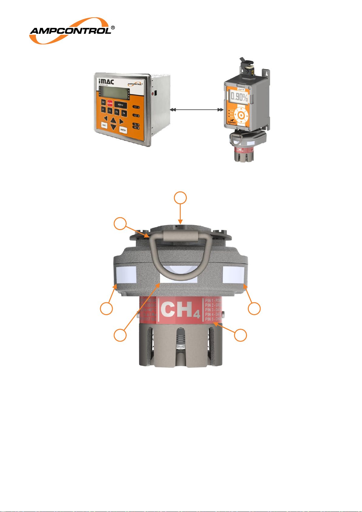
Figure 1: GG2 Example Compatible Modules (iMAC Communication)
Figure 2: GG2 Detector Overview
1.
Proprietary Connector (P1)
2.
Retention clip
3.
Serial number sticker
4.
NATA sticker
5.
Part number sticker
6.
Detector Marking label
iMAC Fieldbus
2
1
3 5
4 6
Page 13
Ampcontrol Pty Ltd – ABN 28 000 915 542
GG2 DETECTOR USER MANUAL
GG2B011
Version 4 – October/2020
Uncontrolled Copy - Refer to Ampcontrol Website for Latest Version
Page 13 of 40
APPROVED FOR EXTERNAL DISTRIBUTION
– PROPERTY OF AMPCONTROL PTY LTD
– NOT TO BE REPRODUCED IN PART
3.4 Markings
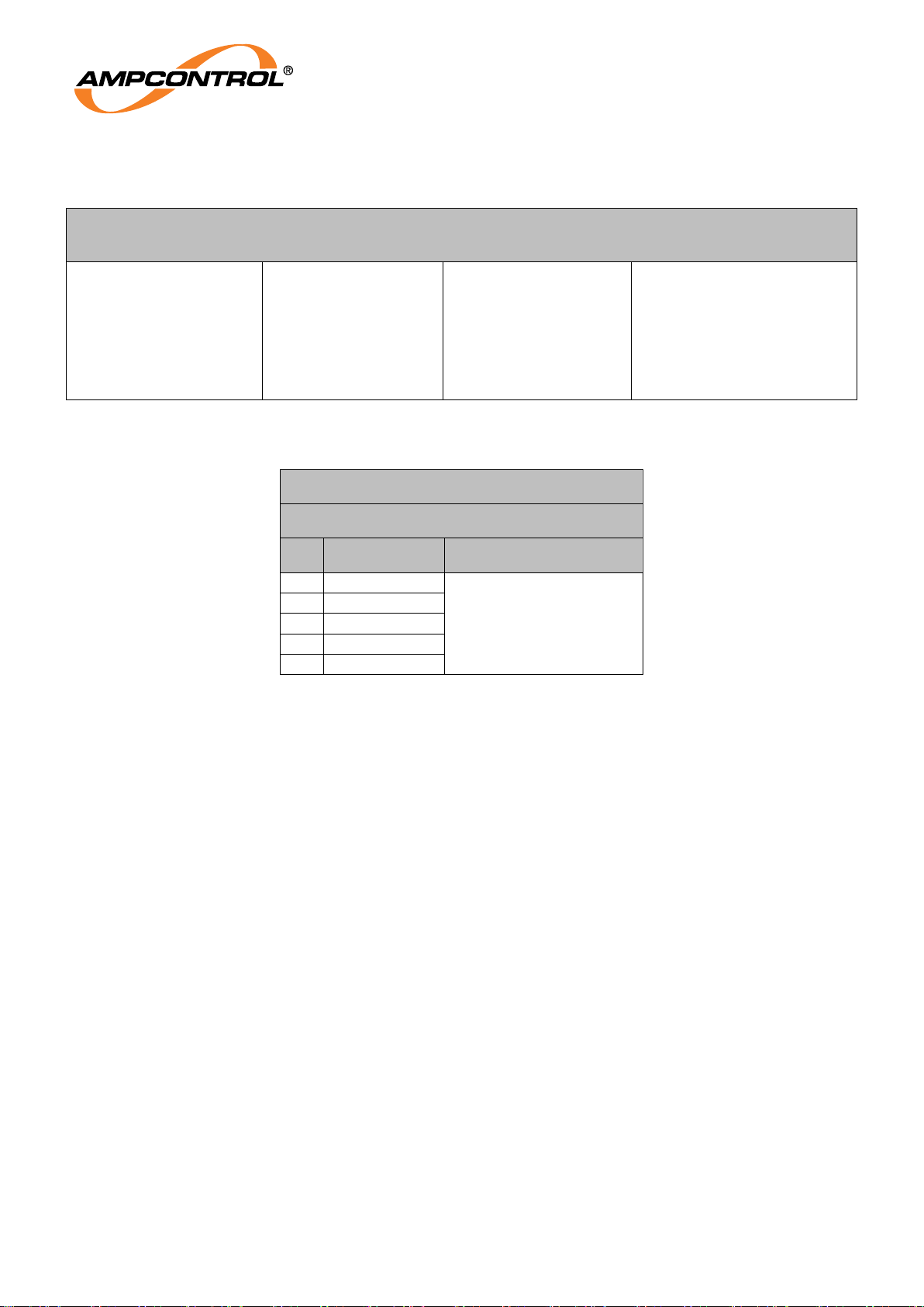
Table 1: Minimum Marking Information
THE MINIMUM MARKING MUST CONTAIN THE INFORMATION IN ONE OF THE FOLLOWING
CELLS
AMPCONTROL
GG2 DETECTOR
NDIR
IECEx TRA 16.0020X
Ex ia I Ma
-20°C ≤ Ta ≤ +40°C
SERIAL: XXXXX
AMPCONTROL
GG2 DETECTOR EC
IECEx TRA
16.0020X
Ex ia I Ma
-20°C ≤ Ta ≤ +40°C
SERIAL: XXXXX
AMPCONTROL
GG2 DETECTOR
CAT
IECEx TRA 16.0020X
Ex ia I Ma
-20°C ≤ Ta ≤ +40°C
SERIAL: XXXXX
AMPCONTROL
GG2 DETECTOR
SENSOR
IECEx TRA 16.0020X
Ex ia I Ma
-20°C ≤ Ta ≤ +40°C
SERIAL: XXXXX
Table 2: Optional Marking Information
Optional Marking Information
Connector P1
Pin
Function
Entity Parameters
1
Power
Ui: 16.5V
Ci: Negligible
Li: Negligible
2
Ground
3
Data -
4
Data +
5
Chassis
3.5 Electrochemical Sensors
3.5.1 Oxygen, Carbon Monoxide and Hydrogen Sulphide Gas Sensors
Oxygen, Carbon Monoxide and Hydrogen Gas Sensors work on the principles of chemical oxidation
and reduction. Electrochemical gas sensors contain electrodes, which promote a chemical reaction
with the target gas when an electrical potential is applied. The chemical reaction of target gas within the
sensor creates a current, which is proportional to the rate of target gas consumption. By measuring this
current, the volume fraction of target gas can be calculated and converted into a digital value by the
integrated sensor electronics. The GG2 Detector is temperature compensated and provides a linear
output.
3.5.2 Humidity
Electrochemical sensors contain an electrolyte, which is a key component of sensor operation. Under
low humidity conditions, the electrolyte can dry out leading to permanent sensor failure. Under high
humidity conditions, the electrolyte can absorb too much water and leak from the sensor.
For Oxygen, Carbon Monoxide and Hydrogen Sulphide, the sensor can be operated in a noncondensing relative humidity of 15% to 90% continuously.
3.5.3 Pressure Effects
Electrochemical sensors are sensitive to the effects of pressure and should not be operated outside of
their stated range of ±20 kPa.
3.5.4 Air Velocity
Electrochemical sensors are insensitive to typical air velocities.
Page 14
Ampcontrol Pty Ltd – ABN 28 000 915 542
GG2 DETECTOR USER MANUAL
GG2B011
Version 4 – October/2020
Uncontrolled Copy - Refer to Ampcontrol Website for Latest Version
Page 14 of 40
APPROVED FOR EXTERNAL DISTRIBUTION
– PROPERTY OF AMPCONTROL PTY LTD
– NOT TO BE REPRODUCED IN PART
3.5.5 Operational Restrictions
Field bump tests and calibrations using portable gas applicators are susceptible to external air
velocities and pressurisation. These phenomena lead to incorrect concentrations of gas being applied
to the detector during calibration, which may result in under reporting the environmental concentration
of gas. The GG2 Calibration Cup and procedures detailed in this manual have been designed to
prevent errors in the calibration process. Use of any calibration cup not detailed in this manual is
prohibited.
3.6 Catalytic Sensors
3.6.1 Methane Gas Sensors
The Methane Gas Sensor, which operates on the catalytic combustible gas detection principle, is a
small platinum element coated in a catalyst. Electrical current is passed through the platinum wire and
the potential of the catalytic element is monitored by a simple Wheatstone Bridge arrangement.
Combustible gases, once in contact with the heated catalytic surface of the measuring element, react
and cause the surface temperature of the element to rise. Any increase in temperature affects the
resistance of the platinum wire, causing a small shift in potential across the Wheatstone Bridge
proportional to the concentration of the combustible gas. The GG2 Detector is temperature
compensated and provides a linear output.
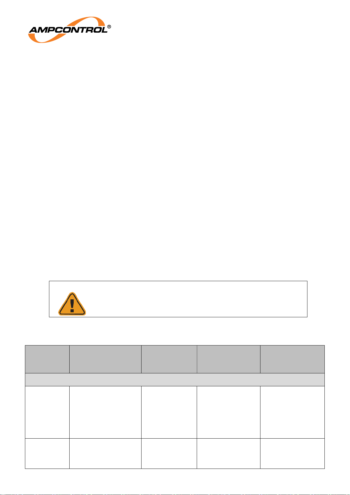
3.6.2 Poisoning of Sensors (Contamination)
High levels of or long exposure to certain compounds may poison the catalytically active detector
filament thereby reducing or destroying its sensitivity.
Among these compounds are halides, sulphur compounds, leaded petrol, silanes, silicates and other
products with silicon. Products such as aerosol sprays, polishes, waxes and lubricants with silicones
and non-catalysed silicone rubbers such as “silastic”, phosphate esters and hydraulic fluids all damage
catalytic sensors.
CAUTION!
Some sensor poisons can cause irreversible damage to the sensor
rendering it unable to detect hazardous gas levels.
Table 3: Poisoning of Sensors
Chemical
Type
Common Examples
Products
Found in:
(Examples)
Effect on
Performance
Duration of
Effect,
PERMANENT POISONS
Silicones
Hexamethyldislioxane
(HMDS)
Dimethicone
Mould Release
Agents
Lubricants
Cosmetics
Cleaning
Products
Signal output on
gas is reduced.
Effect is noticeable
at levels above
2ppm
(continuous
exposure)
Permanent
Organometallic
Compounds
Some Fuels
Petrochemical
Works
Pharmaceutical
Signal output on
gas is reduced.
Effect is noticeable
at levels above
Permanent
Page 15

Ampcontrol Pty Ltd – ABN 28 000 915 542
GG2 DETECTOR USER MANUAL
GG2B011
Version 4 – October/2020
Uncontrolled Copy - Refer to Ampcontrol Website for Latest Version
Page 15 of 40
APPROVED FOR EXTERNAL DISTRIBUTION
– PROPERTY OF AMPCONTROL PTY LTD
– NOT TO BE REPRODUCED IN PART
Plants
2ppm
(continuous
exposure)
Acetylene
Welding
Applications
Some
Petrochemical
Plants
Signal output on
gas is progressively
reduced, Zero
Output increases.
Effect is noticeable
at levels >
5%LEL
(Intermittent
Exposure)
Permanent.
TEMPORARY POISONS
Sulphurous
Compounds
Hydrogen Sulphide
Sewage
Digester Gas
Landfill Gas
Sour Gas
Signal output on
gas is reduced.
Effect is noticeable
at
levels above 2 ppm
(continuous
exposure)
Temporary performance is
restored when
exposed to clean
air or test gas, but
the
sensor’s resistance
to further poisoning
is affected
Chlorinated
Compounds
Carbon Tetrachloride
Methyl Chloride
Some Freons, such
as R134A,
R152B,
Vinyl Chloride
Solvents, Freons
Signal output on
gas is reduced.
Effect is noticeable
at levels above
100 ppm
(continuous
exposure)
Temporary performance is
restored when
exposed to clean
air or test gas, but
the
sensor’s resistance
to further poisoning
is affected
Some
Olefins
Propylene
Styrene
Acrylonitrile
Plastics
Manufacturing
Signal output on
gas is reduced.
Effect is noticeable
at levels above 100
ppm
(intermittent
exposure)
Usually temporary,
except where high
concentrations are
encountered.
3.6.3 Humidity
Catalytic sensors cannot be operated in a condensing atmosphere or where the relative humidity
exceeds 95%. High humidity and condensation can cause significant changes in sensitivity, which
leads to incorrect gas values being read.
3.6.4 Pressure Effects
Catalytic sensors are sensitive to the effects of pressure and should not be operated outside of their
stated range of ±20 kPa.
3.6.5 Air Velocity
Due to the complex dynamics associated within catalytic elements and particle filters, they are slightly
sensitive to changes in air velocity. The GG2 filter assembly has been designed to greatly minimise this
effect.
Page 16

Ampcontrol Pty Ltd – ABN 28 000 915 542
GG2 DETECTOR USER MANUAL
GG2B011
Version 4 – October/2020
Uncontrolled Copy - Refer to Ampcontrol Website for Latest Version
Page 16 of 40
APPROVED FOR EXTERNAL DISTRIBUTION
– PROPERTY OF AMPCONTROL PTY LTD
– NOT TO BE REPRODUCED IN PART
Specialist advice should be sought for applications in extreme air velocities.
3.6.6 Operational Restrictions
Methane gas concentrations above the specified range may cause incorrect operation due to
limitations of the catalytic bead. The catalytic sensor will latch the reading to 5% v/v when the gas
concentration exceeds 5% v/v and will require the user to externally verify the ambient gas
concentration is within the measurement range prior to resetting the latch using the digital latch
command.
After a catalytic sensor has exceeded its measurement range, it is recommended that a bump test be
performed to verify the integrity of the apparatus.
Field bump tests and calibrations using portable gas applicators are susceptible to external air
velocities and pressurisation. These phenomena lead to incorrect concentrations of gas being applied
to the detector during calibration, which may result in under reporting the environmental concentration
of gas. The GG2 Calibration Cup and procedures detailed in this manual have been designed to
prevent errors in the calibration process. Use of any calibration cup not detailed in this manual is
prohibited.
3.7 NDIR Sensors
3.7.1 Methane and Carbon Dioxide Gas Sensors
NDIR Gas Sensors work on the infrared gas absorption principle. An infrared light source illuminates
the sensor through a gas pathway with an optical filter that selects the appropriate wavelength for the
gas being detected; the presence of this gas reduces the amount of infrared energy reaching the
detector. This difference in infrared energy with and without gas is used to measure the amount of gas
present, and is converted to a digital value by the integrated sensor electronics. The GG2 Detector is
temperature compensated and provides a linear output.
3.7.2 Humidity
NDIR sensors cannot operate in a condensing atmosphere. In such an environment, a thin film of water
can form across the membrane, effectively sealing it and stopping the passage of gas into the sensor.
On evaporation of this water, the sensor usually resumes normal operation. Above 90% R.H. the
sensor accumulates water vapour and may form condensation to block the infrared path used for gas
detection. Provided the exposure to these extremes of humidity has not been for a long period, the
sensors will recover when exposed to R.H. in the range 15% to 90%.
3.7.3 Pressure Effects
The NDIR sensors do not exhibit a permanent response to changes of pressure but respond to
pressure on a directly proportional basis.
3.7.4 Air Velocity
NDIR sensors are insensitive to typical air velocities.
3.7.5 Operational Restrictions
Field bump tests and calibrations using portable gas applicators are susceptible to external air
velocities and pressurisation. These phenomena lead to incorrect concentrations of gas being applied
to the detector during calibration, which may result in under reporting the environmental concentration
of gas. The GG2 Calibration Cup and procedures detailed in this manual have been designed to
prevent errors in the calibration process. Use of any calibration cup not detailed in this manual is
prohibited.
3.8 Enclosure
3.8.1 Stainless steel housing
The GG2 Detector circuitry and sensor elements are incorporated in a stainless steel housing. The
Page 17
Ampcontrol Pty Ltd – ABN 28 000 915 542
GG2 DETECTOR USER MANUAL
GG2B011
Version 4 – October/2020
Uncontrolled Copy - Refer to Ampcontrol Website for Latest Version
Page 17 of 40
APPROVED FOR EXTERNAL DISTRIBUTION
– PROPERTY OF AMPCONTROL PTY LTD
– NOT TO BE REPRODUCED IN PART
housing is robust and corrosion resistant. It is suitable for almost all applications and provides for easy
installation.
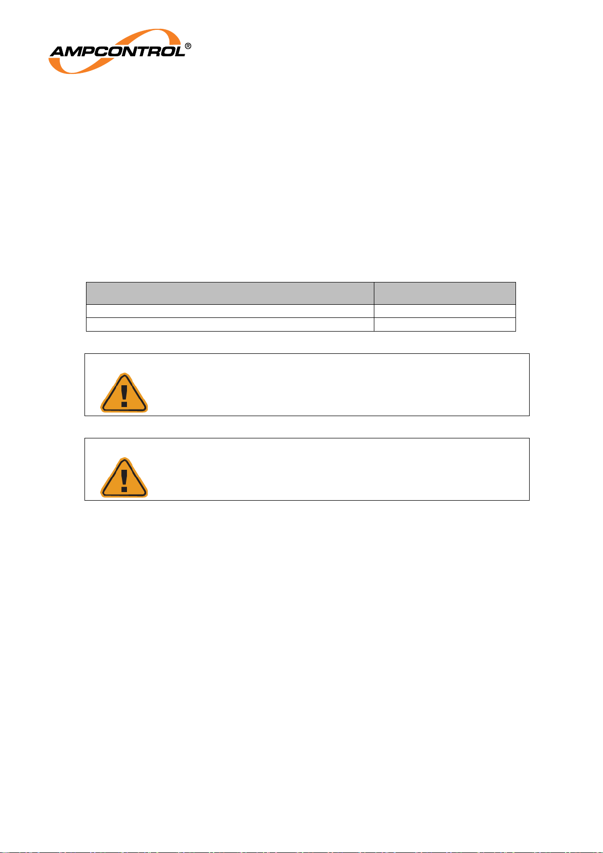
3.8.2 Ingress protection rating:
The GG2 Detector has been designed fit for purpose for the harsh environment of an underground
coalmine.
When mated, the enclosure and electrical connection (P1) achieves an ingress protection rating of IP66.
The gas inlet is fitted with a hydrophobic barrier to prevent liquid water and dust from entering the gas-
sampling chamber. The hydrophobic barrier has a three-dimensional structure to minimise the likelihood
of total blockages occurring.
Table 4: Ingress Protection Rating
Section
Ingress protection rating
The enclosure and electrical connection P1 when mated
IP66
Gas sensing inlet and sensor elements
IP54
CAUTION!
IP ratings do not imply that the equipment will detect gas during and
after exposure to those conditions
CAUTION!
If the Hydrophobic barrier is completely blocked no diffusion can occur
and the GG2 Detector cannot respond to a change in gas concentration
A visual inspection and bump test should be performed if the GG2 Detector has been exposed to
excessive dust and water.
Page 18

Ampcontrol Pty Ltd – ABN 28 000 915 542
GG2 DETECTOR USER MANUAL
GG2B011
Version 4 – October/2020
Uncontrolled Copy - Refer to Ampcontrol Website for Latest Version
Page 18 of 40
APPROVED FOR EXTERNAL DISTRIBUTION
– PROPERTY OF AMPCONTROL PTY LTD
– NOT TO BE REPRODUCED IN PART
3.9 Certification
3.9.1 IEC 60079-11 and IEC 60079-0
Entity parameters listed on the certificate must be taken into account during system commissioning.
The apparatus is designed to be used in hazardous areas and is certified intrinsically safe IECEx TRA
16.0020X. The controlled version of this certificate can be found on the IECEx website
http://iecex.iec.ch/iecex/exs.nsf/ex_eq.xsp?v=e
3.9.2 AS/NZS 60079.29.1:2008 & AS 4641:2007
To maintain compliance with AS/NZS 60079.29.1:2008 a compatible module or user interface shall
have the following features.
1. Three indicating lights utilising the following colour requirements
a) The colour red is used to indicate alarms.
b) The colour yellow is used to indicate faults.
c) The colour green is used to indicate power.
2. On user request, the software version of the GG2 Detector provided through the digital interface
must be displayed.
3.9.3 NSW Government Gazette 52 of June 2015
Extract from MDR Certificate “MDR 0001030 GD”
The ‘Limitations on the use of this Design’ must include the information below as a minimum:
a. Prior to being used, each plant used to determine or monitor the presence of gas must be
tested for accuracy and calibrated by a test facility in Australia that is accredited by the
National Association of Testing Authorities (NATA). The plant must be covered by a NATA
endorsed certificate supplied to the underground coal mine.
b. The plant used to determine or monitor the presence of gas must be maintained in
accordance with Australian Standard AS 2290.3-2018 Electrical equipment for coal mines Introduction, inspection and maintenance - Part 3: Gas detecting and monitoring equipment,
as amended from time to time.
c. Any repair that may affect the instrument’s explosion protection properties must be carried out
at a recognised service facility licensed for that purpose under Part 9 of the Work Health and
Safety (Mines and Petroleum Sites) Regulation 2014.
d. Calibrations must be undertaken in accordance with the manufacturer’s instructions.
Page 19

Ampcontrol Pty Ltd – ABN 28 000 915 542
GG2 DETECTOR USER MANUAL
GG2B011
Version 4 – October/2020
Uncontrolled Copy - Refer to Ampcontrol Website for Latest Version
Page 19 of 40
APPROVED FOR EXTERNAL DISTRIBUTION
– PROPERTY OF AMPCONTROL PTY LTD
– NOT TO BE REPRODUCED IN PART
4 INSTALLATION
The GG2 Detector has been designed to connect and mount from compatible modules. Contact
Ampcontrol for the latest range of compatible modules.
NOTE
The GG2 is suitable for installation in Group 1 hazardous areas.
4.1 General Warnings
These instructions have been designed to assist users of the GG2 Detector with installation.
Before the unit can be installed, there are a number of things that need to be considered and understood
to prevent incorrect or unsafe operation of the unit or the system into which it is installed.
Along with relevant competence, and an understanding of the target application, the following points
should be considered:
4.1.1 Ensure that the information provided in this user manual is fully understood.
It is extremely important that the limitations and functionality of the unit are understood to prevent
incorrect installation and use from creating a potentially dangerous risk. If in doubt as to the nature of
the limitations or their implication, consult a competent authority such as a supervisor or Ampcontrol
technical representative.
4.1.2 Ensure that the application into which the unit is being installed has been properly defined, designed, and approved.
Any system intended to mitigate the risk of injury needs to be properly designed and implemented.
Such a system must be the result of structured risk analysis with the outcomes used to define the
system requirements. These requirements, in turn, will guide the choice of instrumentation, logic
solvers, and actuators needed to implement the system. Understanding the needs of the system will
ensure proper selection of equipment.
4.1.3 Ensure that the unit will properly perform the required functions within the system design.
It is important to understand how the unit is intended to interact with other equipment within a system.
For safe and reliable use, it is crucial that neither the unit’s logical operation nor its signalling be
compromised by incompatibilities with connected equipment. For Group I installations, a full Intrinsic
Safety Audit will be required, along with a correctly specified Safety File. Contact Ampcontrol for
engineering services to undertake these assessments.
4.1.4 Modifications of any form to the unit are prohibited.
The unit as supplied has been designed and manufactured to comply with the requirements of
protection and performance standards. If modifications of any form are made to the unit, the equipment
may no longer be fit for use. If any modifications or damage to the unit is evident, do not use the
equipment and contact Ampcontrol for advice.
4.2 Mandatory Installation Practices
The following information must be adhered to when installing the GG2 Detector. Failure to adhere to this
information may give rise to unsafe operation.
Page 20

Ampcontrol Pty Ltd – ABN 28 000 915 542
GG2 DETECTOR USER MANUAL
GG2B011
Version 4 – October/2020
Uncontrolled Copy - Refer to Ampcontrol Website for Latest Version
Page 20 of 40
APPROVED FOR EXTERNAL DISTRIBUTION
– PROPERTY OF AMPCONTROL PTY LTD
– NOT TO BE REPRODUCED IN PART
Using the unit in a manner that exceeds its electrical, functional or physical specifications, or in a way
that is contrary to its operating restrictions, may result in equipment malfunction or loss of performance
The unit must be powered within the specified voltage range.
The installation of the unit must be carried out by suitably trained and qualified personnel.
Identification labels fixed to the unit must not be damaged, removed or covered before, during or
after installation.
The installation is to be in accordance with the relevant installation Standards/Codes of Practice.
Modifications must not be made to any part of the unit. Modifications to its construction will render
the unit non-compliant.
Complete and accurate records of the installation must be kept as part of the site installation.
Confirm the Intrinsically Safe parameters of the GG2 Detector, cables and power supply are
suitable for the application.
Ensure that the Conditions of Safe Use, listed in the certificate, are adhered to.
4.3 Installation Guidelines
4.3.1 Mounting Location
To ensure continued reliable operation of the GG2 Detector, the following should be considered when
mounting the unit:
Select a suitable central location for mounting with good access. The location should be as clean
and dry as practicable and at a temperature as close to 20°C as practicable.
Mount the sensor unit in a position that reduces the risk of mechanical damage.
Mounting should be to a vertical surface, pointing downwards, allowing for easy wiring access
and subsequent servicing.
It is essential that the sensor be positioned to take into account the expected flow of the gas to be
measured.
Allow sufficient space under the sensor for fitting of calibration cups or accessories.
Ensure to account for the relative density to air of the gas that is being detected.
NOTE
Customised gas panels and systems are also available as well as
sample draw panels. These can be designed specifically to your gas
sensing needs.
For more information call customer service on
1300 267 373
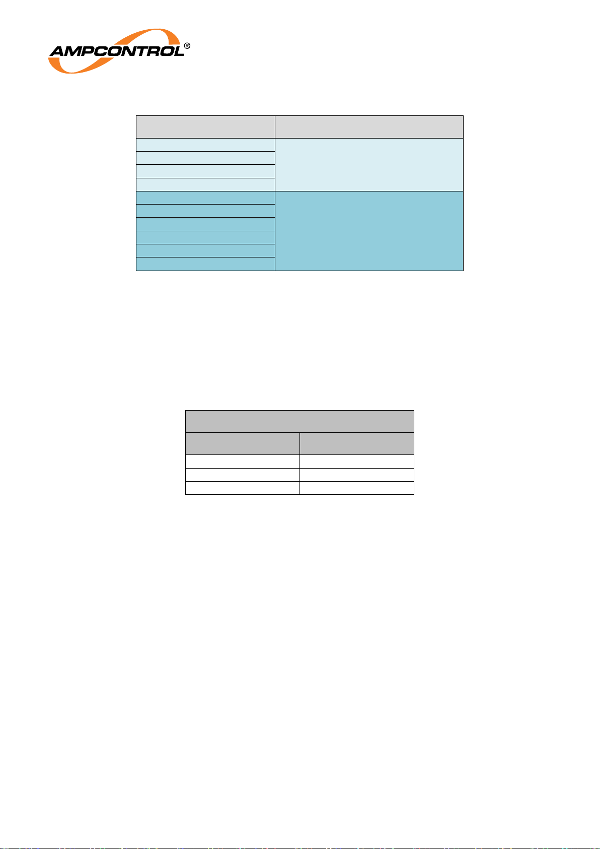
4.3.2 Relative Density of Gas Type
The relative density or buoyancy of the gas or vapour with respect to air determines its propensity to
rise or fall when released into the atmosphere.
Gases or vapours with buoyancy less than air will tend to rise from the source of release.
Conversely, gases or vapours heavier than air will tend to fall and accumulate in concentrations over
long periods of time. Normal air movements in and around such gas concentrations will have the
inevitable effect of producing zones of highly toxic mixtures.
This knowledge of the characteristics of the gas assists when determining the location of the gas
sensor. See Table 5 for gas density values.
For this reason, the detector should be installed in a location that is most suitable for the type of gas
being detected. The services of a Risk Assessment Engineer or specialist should be used if additional
assistance is required in selecting the position of, or the number of sensors required for the application.
Page 21
Ampcontrol Pty Ltd – ABN 28 000 915 542
GG2 DETECTOR USER MANUAL
GG2B011
Version 4 – October/2020
Uncontrolled Copy - Refer to Ampcontrol Website for Latest Version
Page 21 of 40
APPROVED FOR EXTERNAL DISTRIBUTION
– PROPERTY OF AMPCONTROL PTY LTD
– NOT TO BE REPRODUCED IN PART
Table 5: Gas Density Relative to Air
Gas
Density
Hydrogen
Lighter than Air
Ammonia
Methane
Carbon Monoxide
Carbon Dioxide
Heavier than Air
Nitric Oxide
Oxygen
Hydrogen Sulphide
Chlorine
Nitrogen Dioxide
4.4 Conditions of Safe Use
The GG2 Detector has one input circuit connected at P1, made up of pins 1 and 2 supplying power and
ground, and pins 3 and 4 for the communication circuit.
The input parameters of P1 (Pins 1 to 4) are:
Table 6: Conditions of Safe Use
P1: Pins 1, 2, 3, 4
Input Parameters
Ui
16.5V
Ci
negligible
Li
negligible
Page 22
Ampcontrol Pty Ltd – ABN 28 000 915 542
GG2 DETECTOR USER MANUAL
GG2B011
Version 4 – October/2020
Uncontrolled Copy - Refer to Ampcontrol Website for Latest Version
Page 22 of 40
APPROVED FOR EXTERNAL DISTRIBUTION
– PROPERTY OF AMPCONTROL PTY LTD
– NOT TO BE REPRODUCED IN PART
4.5 Mechanical Installation Information
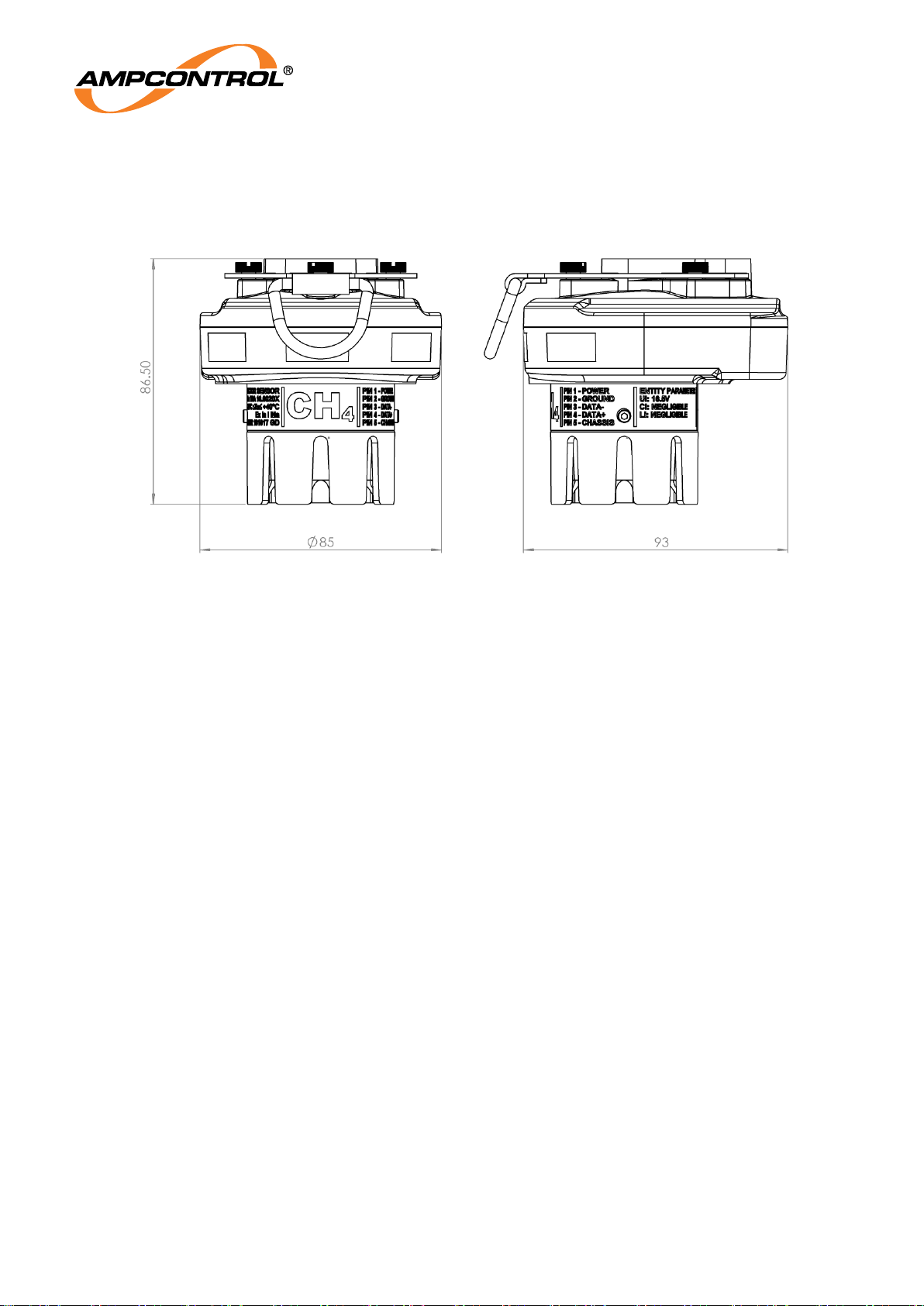
4.5.1 Enclosure Dimensions
Figure 3: GG2 Detector enclosure nominal dimensions (mm)
4.5.2 Mounting Arrangements
The GG2 Detector is mounted using the custom plug interface directly to a compatible module and
secured with the integral retention clip. Optionally, the GG2 detector may be mounted up to 10 meters
away from a compatible module using the optional remote cable assembly. The remote cable assembly
allows the GG2 Detector to be installed in an appropriate position for the target gas.
4.6 Electrical Installation Information
4.6.1 Compatible Module
The GG2 Detector is a part of a GG2 range of products and is designed to interface directly with
compatible modules. Contact Ampcontrol for a current list of compatible modules.
4.6.2 Remote Cable Assembly
The GG2 detector can be mounted remotely from a compatible module using the GG2 remote cable
assembly. The cable is supplied in 10 metre lengths and may be cut to size.
4.6.3 Earthing Procedures
The metallic GG2 Detector chassis is connected to Pin 5 and compatible modules use a high integrity
multiple contact receptacle to equipotential bond the equipment’s chassis together.
The GG2 Remote sensor cable screens are also connected to Pin 5 of the GG2 Detector and bonded
to the chassis of compatible module.
The compatible modules are usually earthed at the power supply.
The GG2 Detector passes the 500V dielectric strength test between intrinsically safe circuits pins 1-4
and the metallic enclosure pin 5.
Page 23
Ampcontrol Pty Ltd – ABN 28 000 915 542
GG2 DETECTOR USER MANUAL
GG2B011
Version 4 – October/2020
Uncontrolled Copy - Refer to Ampcontrol Website for Latest Version
Page 23 of 40
APPROVED FOR EXTERNAL DISTRIBUTION
– PROPERTY OF AMPCONTROL PTY LTD
– NOT TO BE REPRODUCED IN PART
NOTE
GG2 Detector is in conformance to IEC60079.0, section 7.4.2 Dielectric
strength requirement
4.6.4 Detector Wiring and Connectors
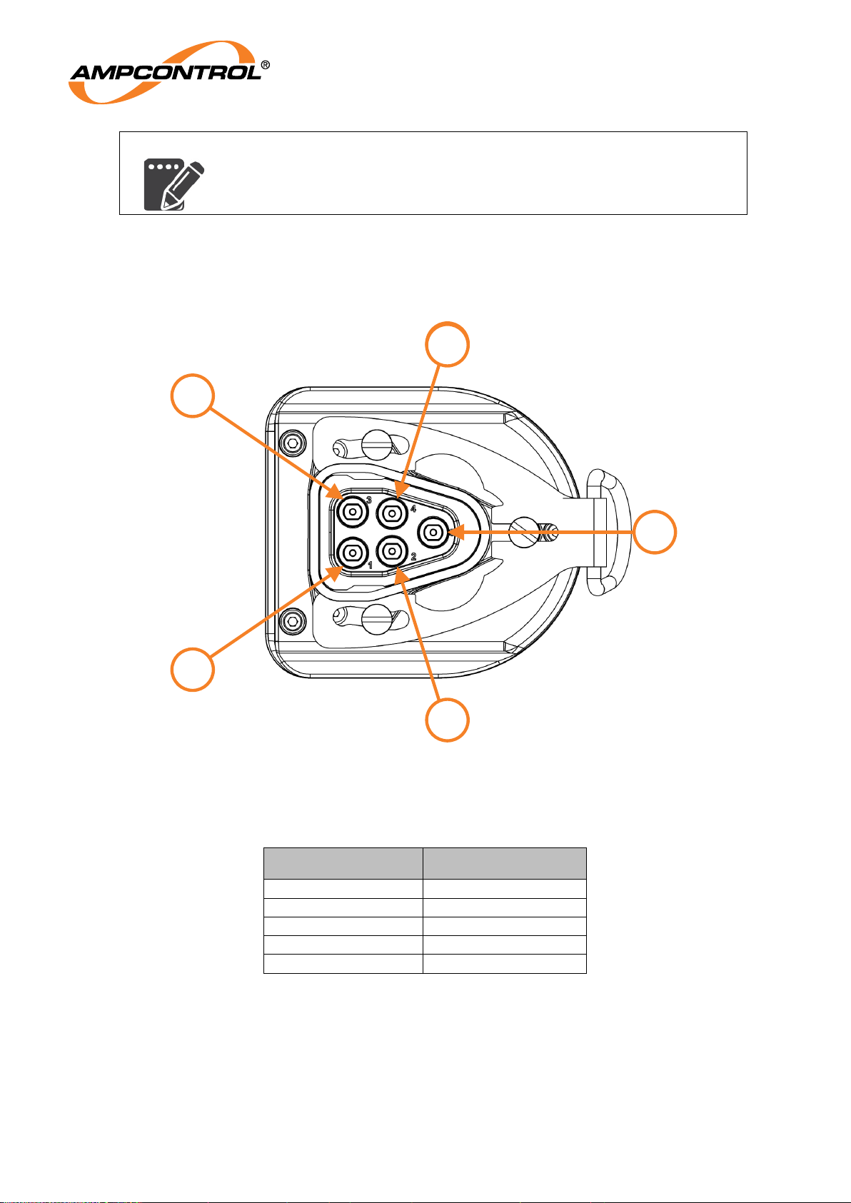
The GG2 Detector has a five-pin connector that interfaces directly to compatible modules available
from Ampcontrol or the remote cable assembly. The connector pins are detailed in Table 7.
Figure 4: GG2 Detector Connector P1 Pin numbering
Table 7: GG2 Detector connector pin out
PIN
FUNCTION
1
POWER
2
GROUND
3
DATA-
4
DATA+
5
CHASSIS
1
3
3
2
4
2
Page 24
Ampcontrol Pty Ltd – ABN 28 000 915 542
GG2 DETECTOR USER MANUAL
GG2B011
Version 4 – October/2020
Uncontrolled Copy - Refer to Ampcontrol Website for Latest Version
Page 24 of 40
APPROVED FOR EXTERNAL DISTRIBUTION
– PROPERTY OF AMPCONTROL PTY LTD
– NOT TO BE REPRODUCED IN PART
5 COMMISSIONING AND CALIBRATION
Commissioning is the performance of initial checks, adjustments and calibration prior to placing the
system in operation for the first time. Calibration, however, is not limited to performance of
commissioning. Calibration is also performed throughout the life of the system on a periodic basis and
after major repairs to the system.
During commissioning and subsequent re-calibration, it is vital to ensure that procedures are followed to
prevent any abnormal sensor signal from initiating any fault, warning or alarm status indicator, or
equipment control function on auxiliary equipment connected to the Detector. Consult the relevant
control unit manual for details of how to do this.
The instruments supplied are NATA calibrated prior to delivery. However, before putting the system into
operation, it is recommended to check the calibration. This is especially important if the instruments are
commissioned sometime after delivery.
5.1 Preliminary Checks
Perform the following preliminary checks:
1. Verify that all connections are correct and installation complete as detailed in Section 4.
2. Check that the correct supply voltage is available to the GG2 Detector.
3. Apply power to the system.
5.2 Calibration
Before the start of calibration, if the GG2 Detector has spent considerable time at low or elevated
temperatures, please allow the device to stabilise to room temperature in powered-up operational (no
fault) state for 24 hours before beginning calibration. If the GG2 Detector has not experienced exposure
to temperature extremes the apparatus should be left in a powered-up operational (no fault) state for one
hour before beginning calibration.
Calibration of sensors can only be achieved by using the appropriate span and zero gas. The volume
fractions of zero and calibration gas components shall be known to a relative uncertainty of ± 2% of the
nominal value.
Refer to GG2B023 GG2 Display User Manual for an overview of calibration and testing procedures.
Calibration gas should be applied to the sensor at a rate of 0.5 to 1.0 litres per minute, using the GG2
Calibration Cup. Allow sufficient time for sensor to stabilize before adjustment.
CAUTION!
GG2 Detectors should be tested regularly to verify proper operation. AS
2290.3 provides guidance depending on the application.
CAUTION!
GG2 Detectors should be NATA calibration at least every 6 months to
ensure their proper operation.
5.3 Calibration Troubleshooting
If during calibration or zero of the GG2 Detector the status indicates a fault or the reading becomes
Page 25

Ampcontrol Pty Ltd – ABN 28 000 915 542
GG2 DETECTOR USER MANUAL
GG2B011
Version 4 – October/2020
Uncontrolled Copy - Refer to Ampcontrol Website for Latest Version
Page 25 of 40
APPROVED FOR EXTERNAL DISTRIBUTION
– PROPERTY OF AMPCONTROL PTY LTD
– NOT TO BE REPRODUCED IN PART
erratic then possible reasons are as follows:
5.3.1 Calibration Error
a) Check the calibration gas. It should be a correct range in air mixture although other trace gases
may be present. Lower percentage gas mixtures will reduce the output leading to unnecessary
change out of the sensor.
b) Check the gas flow to ensure it is 0.5 to 1.0 litres/min.
c) Check sensor is not blocked with dust or mud. The filter cage can be cleaned out with an
antistatic brush before re-attempting calibration.
5.3.2 Zero Error
The sensor zero balance is required to be within a pre-set level and if the sensor is damaged the zero
shift may take it outside the limit. Once this occurs an indication is shown when trying to zero the
instrument, and the sensor should be replaced.
If left in Cal mode the instrument will revert to normal mode after about 2 minutes, retaining its last
settings.
5.3.3 Erratic Readings
Check the calibration cup, gas cylinder and gas lines for leaks or improper flow regulation.
Page 26

Ampcontrol Pty Ltd – ABN 28 000 915 542
GG2 DETECTOR USER MANUAL
GG2B011
Version 4 – October/2020
Uncontrolled Copy - Refer to Ampcontrol Website for Latest Version
Page 26 of 40
APPROVED FOR EXTERNAL DISTRIBUTION
– PROPERTY OF AMPCONTROL PTY LTD
– NOT TO BE REPRODUCED IN PART
6 SERVICE, MAINTENANCE & DISPOSAL
NOTE
If a detector is damaged, a replacement may be obtained from the
manufacturer. See the Conditions of Safe Use for details. Otherwise,
there are no user serviceable parts. For repairs or decommissioning,
return to the manufacturer.
6.1 Equipment Service
A number of external system based checks should be completed on a regular basis. These ‘routine
inspections’ must be carried out by suitably trained people with knowledge of the GG2 Detector and the
systems into which it is fitted. Routine inspections may take the form of either visual-only checks, or
visual and ‘hands-on’ checks.
6.1.1 Visual Only Inspections
A basic visual inspection focuses on looking at the installation for signs of physical damage, water or
dust ingress, and the condition of cables and labels. This type of inspection may involve opening
cabinets to gain access to the unit and other equipment. This level of inspection may also include
cleaning display windows that have become obscured by dirt.
Observations would typically be:
Check that equipment enclosures, cable trays, conduits, etc. are in good order with no physical
damage.
Check that sealed wall boxes are free from water and dust ingress internally. Door seals are in
good condition.
Check that connected cables are free from cuts, abrasions and obvious signs of damage. Cable
restraints are in good order and correctly fitted.
Check that labels on equipment, wall boxes and cables are present and in good condition
(especially certification labels).
Check that no modifications have been carried out to installed equipment.
6.1.2 Hands-On (Detailed) Inspections
A more detailed inspection would include all of the elements of a visual inspection, plus some checks
that cover the integrity of connections, fixtures and fittings.
In addition to basic visual observations, more detailed integrity checks would involve:
Verify that equipment housings, wall boxes and other mechanical fixtures are secured in place.
This includes terminal box lids, tightness of cable glands, integrity of wall-box mountings, security
of equipment fixing to walls/DIN rails etc.
Verify all electrical connections are secure with no loose screw terminals or DIN rail terminals not
fitted to rails etc.
6.2 Equipment Maintenance
Refer to GG2B023 GG2 Display User Manual for an overview of calibration and testing procedures.
6.2.1 Periodic Maintenance
Periodic maintenance consists mainly of scheduled checks to ensure the instrument remains in
adjustment and gives the required response to sampled gas. For recommended maintenance tasks
and schedules, refer to the AS/NZS 2290 series.
Page 27

Ampcontrol Pty Ltd – ABN 28 000 915 542
GG2 DETECTOR USER MANUAL
GG2B011
Version 4 – October/2020
Uncontrolled Copy - Refer to Ampcontrol Website for Latest Version
Page 27 of 40
APPROVED FOR EXTERNAL DISTRIBUTION
– PROPERTY OF AMPCONTROL PTY LTD
– NOT TO BE REPRODUCED IN PART
6.2.2 Corrective Maintenance
During maintenance, it is vital to ensure that suitable procedures are followed to prevent any abnormal
sensor signal from unintentionally operating any fault, warning or alarm status indicator, or equipment
control function. Consult the relevant control unit manual for details as to how to do this.
There are no user serviceable parts. If a fault develops, the detector must be returned to an accredited
repair facility.
Table 8: Corrective Maintenance Checks
Fault
Checks
GG2 Detector will
not respond to
digital commands
a) Check that voltage and polarity applied to the instrument is correct.
b) Check the external interface is wired correctly to a compatible module.
c) Check for loose plug and terminal connections.
GG2 Detector
cannot be
Spanned or
Zeroed
a) Gas element has been damaged or is end of life, return to
manufacturer.
Measurement
range exceeded
a) Apply span gas and verify the result is within accuracy.
Device status
remains in warm-
up continuously
a) Check that voltage and polarity applied to the instrument is correct.
b) Turn the instrument off for >1 min before turning it back on.
c) Gas element has been damaged or is end of life, return to
manufacturer.
T90 Time
exceeded
a) Inspect and remove blockages from the filter cage.
b) Gas element has been damaged or is end of life, return to
manufacturer.
6.3 Disposal
ENVIRO
The electronic equipment discussed in this manual must not be
treated as general waste. By ensuring that this product is disposed of
correctly, you will be helping to prevent potentially negative
consequences for the environment, which could otherwise be caused
by incorrect waste handling of this product.
Page 28

Ampcontrol Pty Ltd – ABN 28 000 915 542
GG2 DETECTOR USER MANUAL
GG2B011
Version 4 – October/2020
Uncontrolled Copy - Refer to Ampcontrol Website for Latest Version
Page 28 of 40
APPROVED FOR EXTERNAL DISTRIBUTION
– PROPERTY OF AMPCONTROL PTY LTD
– NOT TO BE REPRODUCED IN PART
7 SPECIFICATIONS
7.1 Electrochemical O2
Electrical
Supply Voltage
10 - 16.5VDC
Max Power
Consumption
0.1W
Mechanical and Environment
Dimensions (H x W x D)
86.5mm x 85mm x 93mm
Weight
1kg
IP Rating
IP54
Humidity Range
15% to 90% r.h. non-condensing
Temperature Range
-20˚C to + 40˚C
Pressure Range
±20kPa
Response Time (t90)
via diffusion
<60s
Warm-up Time
30 mins
Stabilization time
(for calibration
adjustments)
3 mins
Sensor Unit
Detection Method
Electrochemical
Calibrated Range
0-25%
Accuracy
±0.3% v/v over the range 10% to 25% v/v
±0.5% v/v over the range 0% to 9.9% v/v
Drift
<1% per 3 months
Repeatability
±1% of reading
Sensing Element Life
>48 months
Resolution
<0.1% v/v
1
Certification
IECEx
IECEx TRA 16.0020X
DPI
MDR 0001030 GD
1
The output measurement resolution is consistent across all gas types and does not infer the accuracy of
the gas type
Table 9: Typical Oxygen Cross-Sensitivity
Test Gas Mixture
Instrument variance from
Standard Test Gas
5% Methane in Air
±0.3% Oxygen
0.01% Hydrogen in Air
±0.3% Oxygen
0.1% CO in Air
±0.3% Oxygen
10ppm Hydrogen Sulphide in Air
±0.3% Oxygen
5% Carbon Dioxide in Air
±0.3% Oxygen
10% Carbon Dioxide in Air
±0.4% Oxygen
5% Nitric Oxide in Air
±0.3% Oxygen
5% Nitrogen Dioxide in Air
±0.3% Oxygen
Page 29

Ampcontrol Pty Ltd – ABN 28 000 915 542
GG2 DETECTOR USER MANUAL
GG2B011
Version 4 – October/2020
Uncontrolled Copy - Refer to Ampcontrol Website for Latest Version
Page 29 of 40
APPROVED FOR EXTERNAL DISTRIBUTION
– PROPERTY OF AMPCONTROL PTY LTD
– NOT TO BE REPRODUCED IN PART
7.2 Electrochemical CO
Electrical
Supply Voltage
10 - 16.5VDC
Max power
Consumption
0.1W
Mechanical and Environment
Dimensions (H x W x D)
86.5mm x 85mm x 93mm
Weight
1kg
IP Rating
IP54
Humidity Range
15% to 90% r.h. non-condensing
Temperature Range
-20˚C to + 40˚C
Pressure Range
±20kPa
Response Time (t90)
via diffusion
<60s
Warm-up Time
<5 mins (60 seconds typical)
Stabilization time
(for calibration
adjustments)
3 mins
Sensor Unit
Detection Method
Electrochemical
Calibrated Range
0 - 50 ppm
0 - 100 ppm
Accuracy
±3 ppm over the range 0 ppm to 29 ppm
±6 ppm over the range 30 ppm to 100 ppm
Drift
10% per 6 months
Repeatability
1% reading
Sensing Element Life
>24 months
Resolution
0.01 ppm1
Certification
IECEx
IECEx TRA 16.0020X
DPI
MDR 0001030 GD
1
The output measurement resolution is consistent across all gas types and does not infer the accuracy of
the gas type
Table 10: Typical Carbon Monoxide Cross-Sensitivity
Test Gas Mixture
Instrument variance from
Standard Test Gas
50ppm CO + 5% Methane in Air
±5 ppm CO
50ppm CO + 0.01% Hydrogen in Air
±5 ppm CO
50ppm CO + 10% Oxygen in Nitrogen
±5 ppm CO
50ppm CO + 10 ppm Hydrogen Sulphide in Air
±5 ppm CO
50ppm CO + 5% Carbon Dioxide in Air
±5 ppm CO
50ppm CO + 5% Nitric Oxide in Air
±5 ppm CO
50ppm CO + 5% Nitrogen Dioxide in Air
±5 ppm CO
Page 30

Ampcontrol Pty Ltd – ABN 28 000 915 542
GG2 DETECTOR USER MANUAL
GG2B011
Version 4 – October/2020
Uncontrolled Copy - Refer to Ampcontrol Website for Latest Version
Page 30 of 40
APPROVED FOR EXTERNAL DISTRIBUTION
– PROPERTY OF AMPCONTROL PTY LTD
– NOT TO BE REPRODUCED IN PART
7.3 Electrochemical H2S
Electrical
Supply Voltage
10 - 16.5VDC
Max power
Consumption
0.1W
Mechanical and Environment
Dimensions (H x W x D)
86.5mm x 85mm x 93mm
Weight
1kg
IP Rating
IP54
Humidity Range
15% to 90% r.h. non-condensing
Temperature Range
-20˚C to + 40˚C
Pressure Range
±20kPa
Response Time (t90)
via diffusion
<60s
Warm-up Time
<5 mins (60 seconds typical)
Stabilization time
(for calibration
adjustments)
3 mins
Sensor Unit
Detection Method
Electrochemical
Calibrated Range
0 - 50 ppm
0 - 100 ppm
Accuracy
±1 ppm over the range 0 ppm to 9 ppm
±5 ppm over the range 10 ppm to 100 ppm
Drift
10% per 6 months
Repeatability
1% reading
Sensing Element Life
>24 months
Resolution
0-50 ppm 0.1 ppm
1
0-100 ppm 1 ppm
Certification
IECEx
IECEx TRA 16.0020X
DPI
MDR 0001558 GD
1
The output measurement resolution is consistent across all gas types and does not infer the accuracy of
the gas type
Table 11: Typical Hydrogen Sulphide Cross-Sensitivity
Test Gas Mixture
Instrument variance from
Standard Test Gas
50ppm H2S + 0.01% Hydrogen in Air
±5 ppm H2S
50ppm H2S + 10% Oxygen in Nitrogen
±5 ppm H2S
50ppm H2S + 0.01% Carbon Monoxide in Air
±5 ppm H2S
50ppm H2S + 5% Carbon Dioxide in Air
±5 ppm H2S
50ppm H2S + 5% Nitric Oxide in Air
±5 ppm H2S
50ppm H2S + 5% Nitrogen Dioxide in Air
±5 ppm H2S
7.4 NDIR CH4
Page 31

Ampcontrol Pty Ltd – ABN 28 000 915 542
GG2 DETECTOR USER MANUAL
GG2B011
Version 4 – October/2020
Uncontrolled Copy - Refer to Ampcontrol Website for Latest Version
Page 31 of 40
APPROVED FOR EXTERNAL DISTRIBUTION
– PROPERTY OF AMPCONTROL PTY LTD
– NOT TO BE REPRODUCED IN PART
Electrical
Supply Voltage
10 - 16.5VDC
Max Power
Consumption
0.1W
Mechanical and Environment
Dimensions (H x W x D)
86.5mm x 85mm x 93mm
Weight
1kg
IP Rating
IP54
Humidity Range
15% to 90% r.h. non-condensing
Temperature Range
-20˚C to + 40˚C
Pressure Range
±20kPa
Response Time (t90)
via diffusion
<30s
Warm-up Time
<5 mins (60 seconds typical depending on ambient temperature)
Stabilization time
(for calibration
adjustments)
3 mins
Sensor Unit
Detection Method
Non-dispersive infrared
Calibrated Range
0-5% v/v
Accuracy
±0.1% v/v or ±5% of indication1
Drift
±0.1% v/v or ±5% of indication1 over 3 months
Repeatability
±0.1% v/v or ±5% of indication1
Sensing Element Life
>5 years
Resolution
0.01% v/v2
Certification
IECEx
IECEx TRA 16.0020X
DPI
MDR 0001030 GD
1
Whichever is greater
2
The output measurement resolution is consistent across all gas types and does not infer the accuracy of
the gas type
Table 12: Typical NDIR Methane Cross-Sensitivity
Test Gas Mixture
Instrument variance from
Standard Test Gas
2% Methane + 13% Oxygen in Nitrogen
±0.2% Methane
2% Methane + 5% Carbon Dioxide in Air
±0.2% Methane
2% Methane + 0.075% Ethane in Air
±0.2% Methane
2% Methane + 0.020% Ethane in Air
±0.2% Methane
Page 32

Ampcontrol Pty Ltd – ABN 28 000 915 542
GG2 DETECTOR USER MANUAL
GG2B011
Version 4 – October/2020
Uncontrolled Copy - Refer to Ampcontrol Website for Latest Version
Page 32 of 40
APPROVED FOR EXTERNAL DISTRIBUTION
– PROPERTY OF AMPCONTROL PTY LTD
– NOT TO BE REPRODUCED IN PART
7.5 NDIR CO2
Electrical
Supply Voltage
10 - 16.5VDC
Max power
Consumption
0.1W
Mechanical and Environment
Dimensions (H x W x D)
86.5mm x 85mm x 93mm
Weight
1kg
IP Rating
IP54
Humidity Range
15% to 90% r.h. non-condensing
Temperature Range
-20˚C to + 40˚C
Pressure Range
±20kPa
Response Time (t90)
via diffusion
<60s
Warm-up Time
<5 mins (60 seconds typical)
Stabilization time
(for calibration
adjustments)
3 mins
Sensor Unit
Detection Method
NDIR
Calibrated Range
0-2%
0-5%
Accuracy
±0.05 v/v over the range 0% to 0.5%
10% of applied test gas over the range 0.5% to 2.5%
±0.25 v/v over the range 2.5% to 5%
Drift
±0.05 v/v % v/v or ±5% of indication1 over 3 months
Repeatability
±0.05 v/v
Sensing Element Life
>5 years
Resolution
0.01% v/v2
Certification
IECEx
IECEx TRA 16.0020X
DPI
MDR 0001030 GD
1
Whichever is greater
2
The output measurement resolution is consistent across all gas types and does not infer the accuracy of
the gas type
Table 13: Typical Carbon Monoxide Cross-Sensitivity
Test Gas Mixture
Instrument variance from
Standard Test Gas
0.5% CO2 + 5% Methane in Air
±0.05% CO2
0.5% CO2 + 0.01% Hydrogen in Air
±0.05% CO2
0.5% CO2 + 10% Oxygen in Nitrogen
±0.05% CO2
0.5% CO2 + 10 ppm Hydrogen Sulphide in Air
±0.05% CO2
0.5% CO2 + 5% Carbon Dioxide in Air
±0.05% CO2
0.5% CO2 + 5% Nitric Oxide in Air
±0.05% CO2
0.5% CO2 + 5% Nitrogen Dioxide in Air
±0.05% CO2
Page 33

Ampcontrol Pty Ltd – ABN 28 000 915 542
GG2 DETECTOR USER MANUAL
GG2B011
Version 4 – October/2020
Uncontrolled Copy - Refer to Ampcontrol Website for Latest Version
Page 33 of 40
APPROVED FOR EXTERNAL DISTRIBUTION
– PROPERTY OF AMPCONTROL PTY LTD
– NOT TO BE REPRODUCED IN PART
7.6 Catalytic CH4
Electrical
Supply Voltage
10 - 16.5VDC
Maximum Power
Consumption
1W
Mechanical & Environmental
Dimensions (H x W x D)
86.5mm x 85mm x 93mm
Weight
1kg
IP Rating
IP54
Humidity Range
0% to 95% r.h. non-condensing
Temperature Range
-20˚C to + 40˚C
Pressure Range
±20kPa
Response Time (t90) via
diffusion
<30 seconds
Warm-up Time
<5 mins (60 seconds typical)
Stabilization time
(for calibration
adjustments)
3 mins
Sensor Unit
Detection Method
Catalytic2
Calibrated Range
0-5%
Accuracy
±0.1% v/v or ±5% of indication1
Drift
±0.1% v/v or ±5% of indication1 over 3 months
Repeatability
±0.1% v/v or ±5% of indication1
Sensing Element Life
>24 months
Resolution
0.01% v/v3
Certification
IECEx
IECEx TRA 16.0020X
DPI
MDR 0001030 GD
1
Whichever is greater
2
Catalytic sensors require oxygen to operate
3
The output measurement resolution is consistent across all gas types and does not infer the accuracy of
the gas type
Table 14: Cross sensitivity of catalytic methane gas sensors
Test Gas Mixture
Instrument Variance From
Standard Test Gas
2% Methane + 13% Oxygen in Nitrogen
±0.2% Methane
2% Methane + 5% Carbon Dioxide in Air
±0.2% Methane
2% Methane + 0.075% Ethane in Air
±0.2% Methane
2% Methane + 0.020% Ethane in Air
±0.2% Methane
Page 34

Ampcontrol Pty Ltd – ABN 28 000 915 542
GG2 DETECTOR USER MANUAL
GG2B011
Version 4 – October/2020
Uncontrolled Copy - Refer to Ampcontrol Website for Latest Version
Page 34 of 40
APPROVED FOR EXTERNAL DISTRIBUTION
– PROPERTY OF AMPCONTROL PTY LTD
– NOT TO BE REPRODUCED IN PART
8 EQUIPMENT LIST
NOTE
Customised gas panels and systems are also available as well as
sample draw panels. These can be designed specifically to your
gas sensing needs.
Refer to GG2B026 GG2 Monitoring Solution Technical Datasheet for
a detailed equipment list.
For more information call customer service on
1300 267 373
Part Number
Category
Description
177870
5%
GG2 Detector NDIR CH4 5%
180733
5%
GG2 Detector NDIR CO2 5%
180734
5%
GG2 Detector NDIR CO2 2%
177871
5%
GG2 Detector CAT CH4 5%
177872
25%
GG2 Detector EC O2 25%
177873
50 ppm
GG2 Detector EC CO 50 ppm
177874
100 ppm
GG2 Detector EC CO 100 ppm
192855
50 ppm
GG2 Detector EC H2S 50 ppm
193071
100 ppm
GG2 Detector EC H2S 100 ppm
177875
Accessory
GG2 Calibration Cup
177876
Accessory
GG2 Connector Dust Cover
178994
Accessory
GG2 Remote Sensor Cable Connection Module
177878
Accessory
GG2 Retainer Clip
Page 35

Ampcontrol Pty Ltd – ABN 28 000 915 542
GG2 DETECTOR USER MANUAL
GG2B011
Version 4 – October/2020
Uncontrolled Copy - Refer to Ampcontrol Website for Latest Version
Page 35 of 40
APPROVED FOR EXTERNAL DISTRIBUTION
– PROPERTY OF AMPCONTROL PTY LTD
– NOT TO BE REPRODUCED IN PART
9 APPROVALS
9.1 MDR 0001030 GD
The GG2 Detector has be independently tested by the Mine Safety Technology Centre and several
reports for different gas types were used to register the product for use in NSW underground Coalmines.
The performance criteria assessed was taken from NSW Government Gazette No 52 of 26 June 2015,
which incorporates conformance to both AS/NZS 60079-29.1:2008 and AS/NZS 4641:2007
While the design order does incorporate conformance to the two Australian standards, there are sections
in the Design Order, which are to a lower standard to that of aforementioned standards;
Catalytic CH4 Detector - Long-term Stability Test
o The Mine Safety Technology Centre was engaged to verify the performance of the
catalytic detector to AS/NZS 60079.29.1 and the NSW regulatory requirements. The test
report issued states compliance with the long-term stability test however; this test was
shortened from 33 days in total to 26 days in total.
Electrochemical O2 Detector - Cross Sensitivity Test
AS/NZS 4641 Electrical apparatus for detection of oxygen and other gases and vapours
at toxic levels—General requirements and test methods, state that the concentration
indicated by the output signal shall not vary from the test gas concentration by more than
a volume fraction of ±0.3% v/v over the range 10% - 25% v/v oxygen, when exposed to
the standards nominated combinations of laboratory test gasses. However when
independently tested by MSTC the 0-25% range Oxygen Sensor - Electrochemical
(177872) was found to vary from the test gas concentration by a volume fraction ±0.4%
v/v oxygen when exposed to the test gas combination containing 10% Carbon Dioxide.
o The warmup time is the time interval, (with the equipment in a stated atmosphere),
between the time when the equipment is switched on and the time when the indication
reaches and remains within the stated tolerances. The warmup time of the O2 detector for
a cold start is 30 Minutes.
9.2 MDR 0001558 GD
MDR 0001558 GD has be independently tested by the Mine Safety Technology Centre and the
performance report was used to register the product for use in NSW underground Coalmines.
9.3 IECEx TRA 16.0020X
The official controlled version of the certificate may be obtained online from the IECEx website
The attached certificate below was current when this document was published but is to be considered an
uncontrolled version.
Page 36
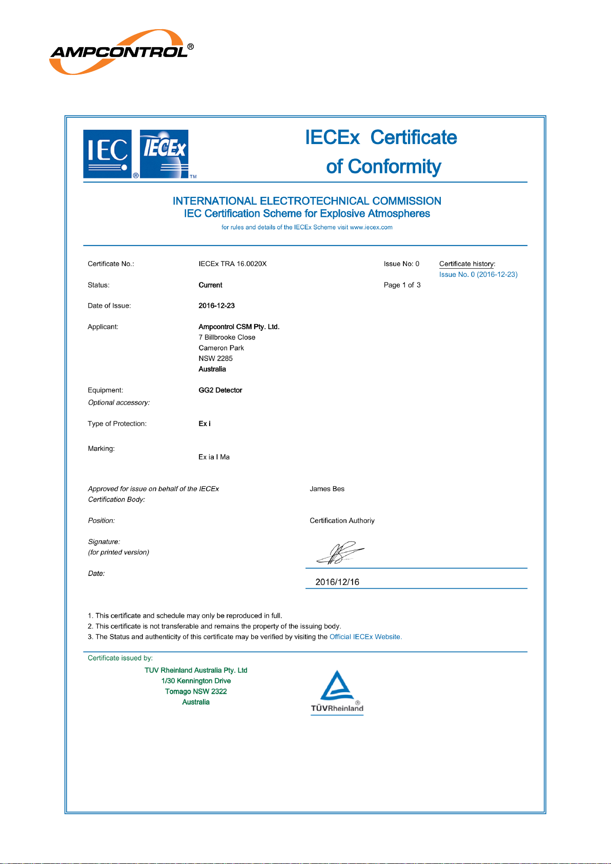
Ampcontrol Pty Ltd – ABN 28 000 915 542
GG2 DETECTOR USER MANUAL
GG2B011
Version 4 – October/2020
Uncontrolled Copy - Refer to Ampcontrol Website for Latest Version
Page 36 of 40
APPROVED FOR EXTERNAL DISTRIBUTION
– PROPERTY OF AMPCONTROL PTY LTD
– NOT TO BE REPRODUCED IN PART
Page 37

Ampcontrol Pty Ltd – ABN 28 000 915 542
GG2 DETECTOR USER MANUAL
GG2B011
Version 4 – October/2020
Uncontrolled Copy - Refer to Ampcontrol Website for Latest Version
Page 37 of 40
APPROVED FOR EXTERNAL DISTRIBUTION
– PROPERTY OF AMPCONTROL PTY LTD
– NOT TO BE REPRODUCED IN PART
Page 38

Ampcontrol Pty Ltd – ABN 28 000 915 542
GG2 DETECTOR USER MANUAL
GG2B011
Version 4 – October/2020
Uncontrolled Copy - Refer to Ampcontrol Website for Latest Version
Page 38 of 40
APPROVED FOR EXTERNAL DISTRIBUTION
– PROPERTY OF AMPCONTROL PTY LTD
– NOT TO BE REPRODUCED IN PART
Page 39
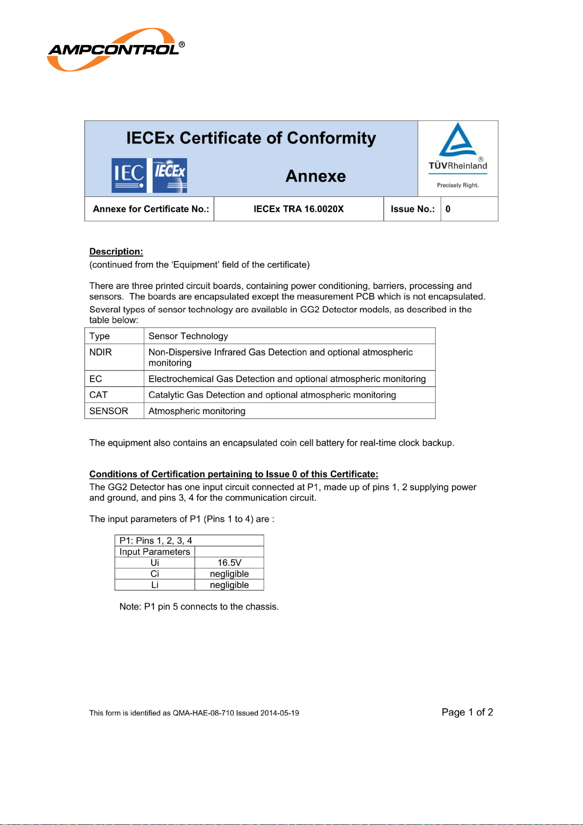
Ampcontrol Pty Ltd – ABN 28 000 915 542
GG2 DETECTOR USER MANUAL
GG2B011
Version 4 – October/2020
Uncontrolled Copy - Refer to Ampcontrol Website for Latest Version
Page 39 of 40
APPROVED FOR EXTERNAL DISTRIBUTION
– PROPERTY OF AMPCONTROL PTY LTD
– NOT TO BE REPRODUCED IN PART
Page 40
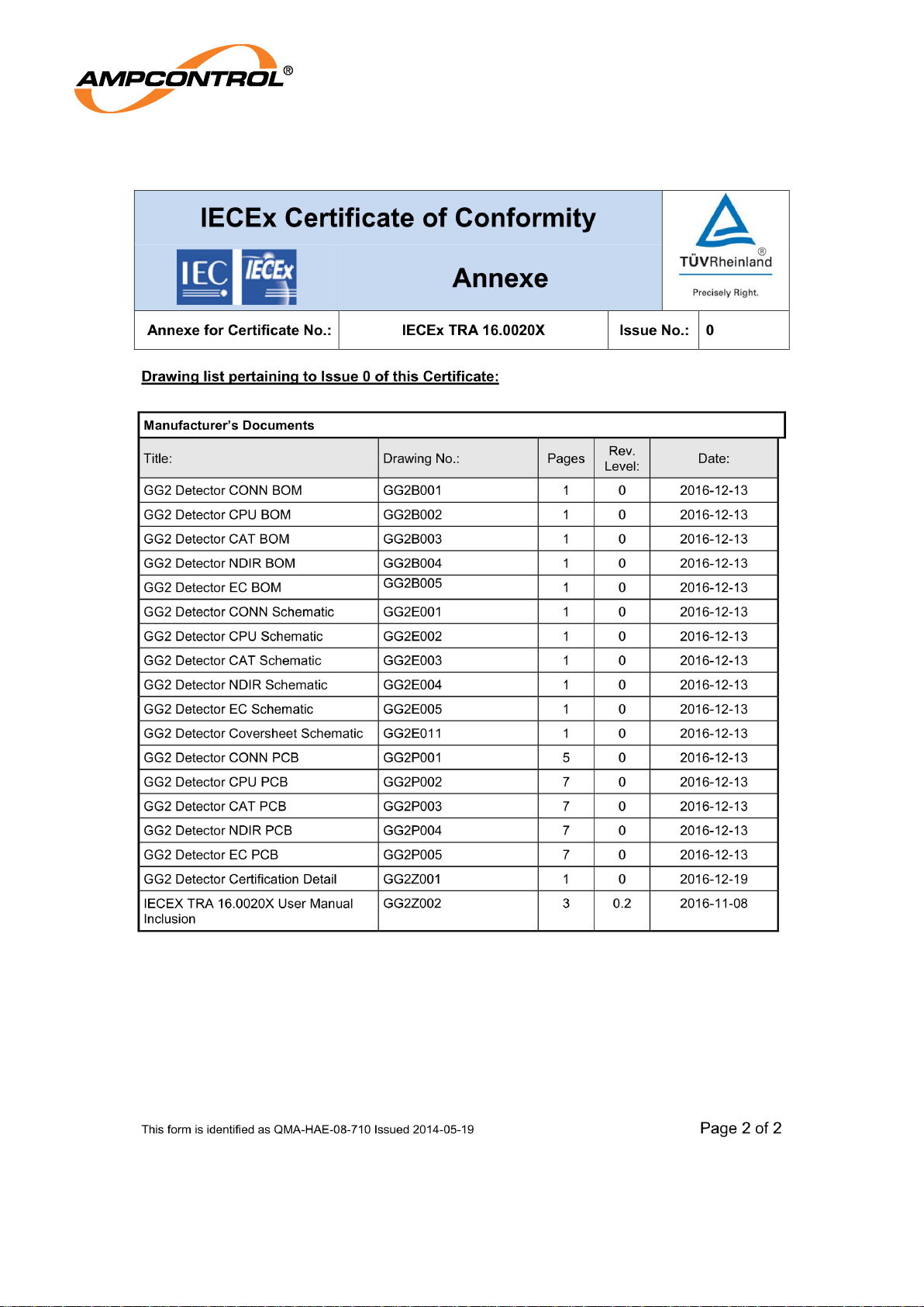
Ampcontrol Pty Ltd – ABN 28 000 915 542
GG2 DETECTOR USER MANUAL
GG2B011
Version 4 – October/2020
Uncontrolled Copy - Refer to Ampcontrol Website for Latest Version
Page 40 of 40
APPROVED FOR EXTERNAL DISTRIBUTION
– PROPERTY OF AMPCONTROL PTY LTD
– NOT TO BE REPRODUCED IN PART
 Loading...