

Page 1

Smart choice for power
Xantrex Technology Inc.
Programmable Products
9250 Brown Deer Road
San Diego, CA 92121
USA
858 450 0085 Phone
858 458 0257 Fax
www.programmablepower.com
SLM-Series AC/DC
Electronic Load
Operating and Programming
Manual
M540072-01 Rev B www.programmablepower.com
Page 2

Page 3

Page 4

Page 5

About Xantrex
Xantrex Technology Inc. is a world-leading supplier of advanced power electronics and
controls with products from small mobile units to utility-scale systems for wind, solar,
batteries, fuel cells, microturbines, and backup power applications in both gridconnected and stand-alone systems. Xantrex products include inverters, battery
chargers, programmable power supplies, and variable speed drives that convert, supply,
control, clean, and distribute electrical power.
Trademarks
SLM-Series AC/DC Electronic Load is a trademark of Xantrex International. Xantrex is a
registered trademark of Xantrex International.
Other trademarks, registered trademarks, and product names are the property of their
respective owners and are used herein for identification purposes only.
Notice of Copyright
SLM-Series AC/DC Electronic Load
2007 Xantrex International. All rights reserved.
Exclusion for Documentation
UNLESS SPECIFICALLY AGREED TO IN WRITING, XANTREX TECHNOLOGY INC.
(“XANTREX”)
(a) MAKES NO WARRANTY AS TO THE ACCURACY, SUFFICIENCY OR SUITABILITY OF
ANY TECHNICAL OR OTHER INFORMATION PROVIDED IN ITS MANUALS OR OTHER
DOCUMENTATION.
(b) ASSUMES NO RESPONSIBILITY OR LIABILITY FOR LOSSES, DAMAGES, COSTS OR
EXPENSES, WHETHER SPECIAL, DIRECT, INDIRECT, CONSEQUENTIAL OR INCIDENTAL,
WHICH MIGHT ARISE OUT OF THE USE OF SUCH INFORMATION. THE USE OF ANY
SUCH INFORMATION WILL BE ENTIRELY AT THE USER’S RISK, AND
(c) REMINDS YOU THAT IF THIS MANUAL IS IN ANY LANGUAGE OTHER THAN
ENGLISH, ALTHOUGH STEPS HAVE BEEN TAKEN TO MAINTAIN THE ACCURACY OF THE
TRANSLATION, THE ACCURACY CANNOT BE GUARANTEED. APPROVED XANTREX
CONTENT IS CONTAINED WITH THE ENGLISH LANGUAGE VERSION WHICH IS POSTED
AT WWW.PROGRAMMABLEPOWER.COM.
Operating and Programming Manual © December
Date and Revision
December 2007 Revision B
Part Number
M540072-01
Contact Information
Telephone: 800 733 5427 (toll free in North America)
858 450 0085 (direct)
Fax: 858 458 0267
Email: sales@programmablepower.com
service@programmablepower.com
Web: www.programmablepower.com
i
Page 6

This page intentionally left blank.
ii
Page 7

Important Safety Instructions
Before applying power to the system, verify that your product is configured properly for your
particular application.
WARNING
Only
qualified personnel
perform installation and servicing.
Ensure that the AC power line ground is connected properly to the Power Rack input connector or
chassis. Similarly, other power ground lines including those to application and maintenance
equipment
Always ensure that facility AC input power is de-energized prior to connecting or disconnecting
any cable.
In normal operation, the operator does not have access to hazardous voltages within the chassis.
However, depending on the user’s application configuration, HIGH VOLTAGES HAZARDOUS
TO HUMAN SAFETY may be normally generated on the output terminals. The customer/user
must ensure that the output power lines are labeled properly as to the safety hazards and that
any inadvertent contact with hazardous voltages is eliminated.
Guard against risks of electrical shock during open cover checks by not touching any portion of
the electrical circuits. Even when power is off, capacitors may retain an electrical charge. Use
safety glasses during open cover checks to avoid personal injury by any sudden component
failure.
must
Hazardous voltages may be present when covers are removed.
Qualified personnel must use extreme caution when servicing this
equipment. Circuit boards, test points, and output voltages also may
be floating above (below) chassis ground.
who deal with attendant hazards in power supplies, are allowed to
be grounded properly for both personnel and equipment safety.
SAFETY SYMBOLS
iii
Page 8

This page intentionally left blank.
iv
Page 9

Product Family: SLM-Series AC/DC Electronic Load
Warranty Period: One (1) Year
WARRANTY TERMS
Xantrex provides this written warranty covering the Product stated above, and if the
Buyer discovers and notifies Xantrex in writing of any defect in material or workmanship
within the applicable warranty period stated above, then Xantrex may, at its option:
repair or replace the Product; or issue a credit note for the defective Product; or provide
the Buyer with replacement parts for the Product.
The Buyer will, at its expense, return the defective Product or parts thereof to Xantrex in
accordance with the return procedure specified below. Xantrex will, at its expense,
deliver the repaired or replaced Product or parts to the Buyer. Any warranty of Xantrex
will not apply if the Buyer is in default under the Purchase Order Agreement or where
the Product or any part thereof:
• is damaged by misuse, accident, negligence or failure to maintain the same as
specified or required by Xantrex;
• is damaged by modifications, alterations or attachments thereto which are not
authorized by Xantrex;
• is installed or operated contrary to the instructions of Xantrex;
• is opened, modified or disassembled in any way without Xantrex’s consent; or
• is used in combination with items, articles or materials not authorized by Xantrex.
The Buyer may not assert any claim that the Products are not in conformity with any
warranty until the Buyer has made all payments to Xantrex provided for in the Purchase
Order Agreement.
PRODUCT RETURN PROCEDURE
1. Request a Return Material Authorization (RMA) number from the repair facility (must be
done in the country in which it was purchased):
• In the USA, contact the Xantrex Repair Department prior to the return of the
product to Xantrex for repair:
Telephone: 800-733-5427, ext. 2295 or ext. 2463 (toll free North America)
858-450-0085, ext. 2295 or ext. 2463 (direct)
• Outside the United States, contact the nearest Authorized Service Center
(ASC). A full listing can be found either through your local distributor or our
website, www.programmablepower.com, by clicking Support and going to the
Service Centers tab.
2. When requesting an RMA, have the following information ready:
• Model number
• Serial number
• Description of the problem
NOTE: Unauthorized returns will not be accepted and will be returned at the
shipper’s expense.
NOTE: A returned product found upon inspection by Xantrex, to be in specification is
subject to an evaluation fee and applicable freight charges.
WA-1
Page 10

This page intentionally left blank.
WA-2
Page 11

Important Safety Instructions
This manual has been written expressly for the Sorensen brand SLM series of electronic loads,
which have been designed and certified to meet the Low Voltage and Electromagnetic
Compatibility Directive Requirements of the European Community.
Since the goal of the Low Voltage Directive is to ensure the safety of the equipment operator,
universal graphic symbols have been used both on the unit itself and in this manual to warn the
operator of potentially hazardous situations (see Safety Information).
v
Page 12

This page intentionally left blank.
vi
Page 13

CONTENTS
SECTION 1 FEATURES, FUNCTIONS, AND SPECIFICATIONS ....1-1
1.1 General Description ......................................................................................... 1-1
1.1.1 Power Contours ................................................................................... 1-1
1.1.2 Operating Modes ................................................................................. 1-4
1.2 Features and Functions................................................................................... 1-5
1.3 Accessories ..................................................................................................... 1-5
1.4 Specifications................................................................................................... 1-6
1.5 Regulatory Compliance ................................................................................... 1-6
SECTION 2 INSTALLATION AND MAINTENANCE .......................2-1
2.1 Introduction...................................................................................................... 2-1
2.2 Inspection ........................................................................................................ 2-1
2.2.1 Installation............................................................................................ 2-1
2.2.2 Removal............................................................................................... 2-2
2.2.3 Environmental Requirements .............................................................. 2-2
2.2.4 Service or Repair ................................................................................. 2-2
2.3 Connections..................................................................................................... 2-3
2.3.1 Input Binding Post and Wire Considerations ....................................... 2-3
2.3.2 Voltage Sensing Input (Vsense) BNC Connector. ............................... 2-4
2.3.3 RS-232C and GPIB Connections ........................................................ 2-4
2.4 Maintenance .................................................................................................... 2-4
SECTION 3 OPERATION...............................................................3-1
v
3.1 Front Panel Controls and Indicators ................................................................ 3-1
3.2 Set-up Procedures........................................................................................... 3-5
3.2.1 Pass / Fail Limits, Go/No GO Limits .................................................... 3-5
Page 14

Contents SLM-Series AC/DC Load
3.2.2 Frequency Setting: ...............................................................................3-6
3.2.3 Current Synchronization.......................................................................3-6
3.2.4 Crest Factor .........................................................................................3-7
3.2.5 Display Setting .....................................................................................3-8
3.3 Normal Operation...........................................................................................3-10
3.3.1 CC Mode: ...........................................................................................3-10
3.3.2 Crest Factor Selection:.......................................................................3-10
3.3.3 CR Mode ............................................................................................3-11
3.4 Initial Settings of SLM-Series AC/DC Electronic Load ...................................3-13
3.4.2 Load current course/fine increase/decrease adjustment key.............3-14
3.5 Protection Features........................................................................................3-15
3.5.1 Over Voltage Protection (OVP) ..........................................................3-15
3.5.2 Over Current Protection (OCP) .........................................................3-15
3.5.3 Over Power Protection (OPP) ............................................................3-15
3.5.4 Over Temperature Protection (OTP)..................................................3-16
SECTION 4 GPIB/RS-232 PROGRAMMING OPERATION ............. 4-1
4.1 Introduction ......................................................................................................4-1
4.2 GPIB Commands .............................................................................................4-1
4.3 RS-232 Interface and Commands....................................................................4-1
4.4 GPIB/RS-232C Command List.........................................................................4-2
4.4.1 Command Syntax Abbreviations..........................................................4-2
4.5 GPIB/RS-232 Command Description...............................................................4-7
4.5.1 Setting Commands...............................................................................4-7
4.5.2 Query Commands ..............................................................................4-20
APPENDIX A GPIB Programming Example...................................... A-1
APPENDIX B RS-232 Programming Example .................................. B-1
APPENDIX C SLM-Series AC/DC
Flow Chart.................................................................. C-1
LIST OF FIGURES
Figure 1-1 SLM-60-20-300 Electronic Load Power Curve ........................................... 1-1
Figure 1-2 SLM-150-8-300 Electronic Load Power Curve ........................................... 1-2
Figure 1-3 SLM-300-4-300 Electronic Load Power Curve ........................................... 1-2
Figure 1-4 SLM-500-1-300 Electronic Load Power Curve ........................................... 1-3
Figure 1-5 Characteristics of CC Mode........................................................................ 1-4
Figure 1-6 Characteristics of CR Mode........................................................................ 1-4
Figure 2-1 Plug-in Installation and Removal ................................................................ 2-2
Load GPIB/RS-232 Operating
vi
Page 15

SLM-Series AC/DC Load Contents
Figure 2-2 Connection Method for Small Load Current Condition................................2-4
Figure 2-3 Typical Connection for SLM-Series AC/DC Electronic Load.......................2-4
Figure 3-1 Front Panel of SLM-Series AC/DC Electronic Load....................................3-1
Figure 3-2 Front Panel Button Functions for SLM-Series AC/DC Unit .........................3-5
Figure 3-3 Illustration of Sync.......................................................................................3-7
Figure 3-4 SLM-Series AC/DC Electronic Load Module Setup Flow Chart..................3-9
Figure 3-5 SLM-Series AC/DC Electronic Load Operation Flow Char .......................3-12
Figure 4-1 RS-232 Interface Diagram ..........................................................................4-2
Figure 4-2 Protection Status Register ........................................................................4-23
Figure 4-3 Error Status Byte Register ........................................................................4-23
LIST OF TABLES
Table 1-1 SLM-Series AC/DC Specifications ...............................................................1-6
Table 3-1 Built in Crest Factor Settings by Bank andKkey Selection ...........................3-7
Table 3-2 SLM Series AC/DC Module Factory/Reset Settings ..................................3-14
Table 3-3 Range, Resolution, andCoarse/Fine and Increment/Decrement Values....3-15
Table 3-4 SLH AC-series Protection Setting Values ..................................................3-16
Table 4-1 GPIB Command Terminator.........................................................................4-3
Table 4-2 GPIB/RS-232 Setting Command Summary .................................................4-4
Table 4-3 GPIB/RS-232 Preset Query Command Summary with Applicable Module
Types............................................................................................................4-4
Table 4-4 State Command Summary ...........................................................................4-5
Table 4-5 System Commands - All Modules ................................................................4-6
Table 4-6 Measure and Limit Commands ....................................................................4-6
Table 4-7 Global Commands........................................................................................4-6
Table 4-8 Waveform Information ................................................................................4-14
vii
Page 16

Contents SLM-Series AC/DC Load
This page intentionally left blank.
viii
Page 17
V
FEATURES, FUNCTIONS,
AND SPECIFICATIONS
1.1 GENERAL DESCRIPTION
SLM-Series, AC/DC Electronic Load is used to test the specification characteristics of
AC/DC high power suppliers and the service life characteristics of batteries.
The load works with GPIB interface and front panel manual operation.
SECTION 1
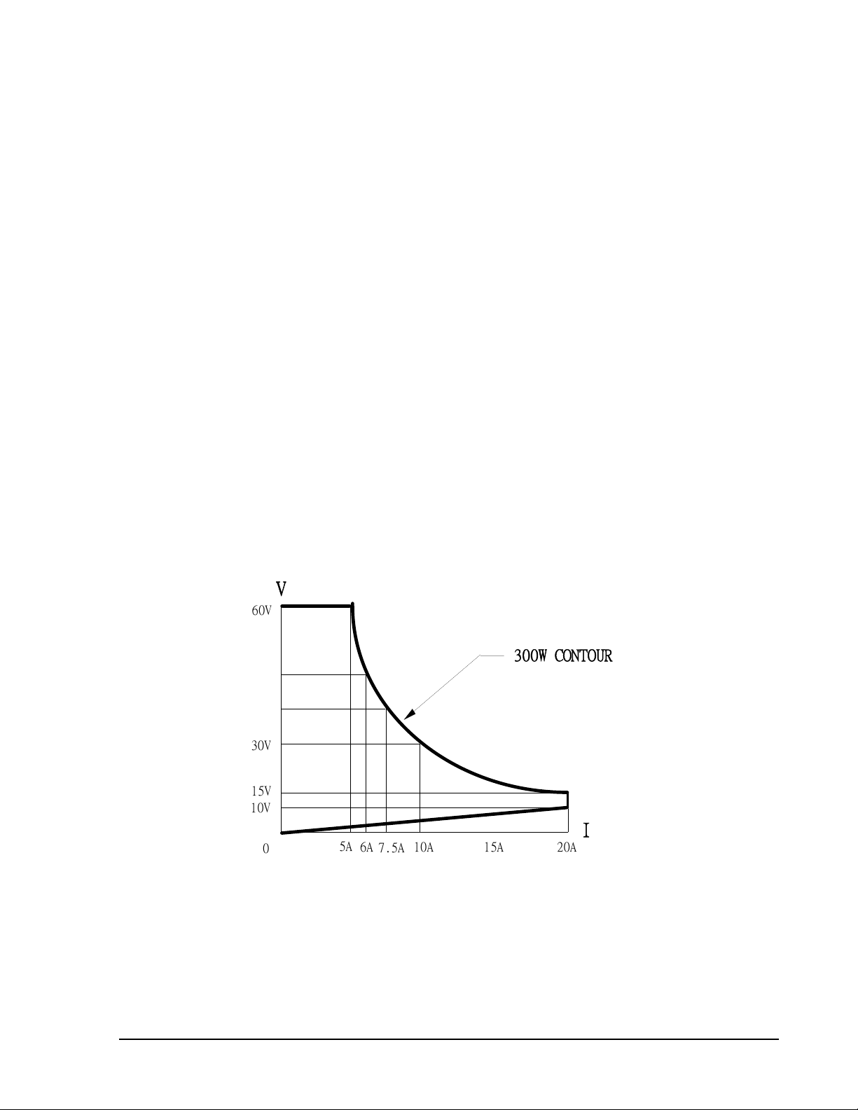
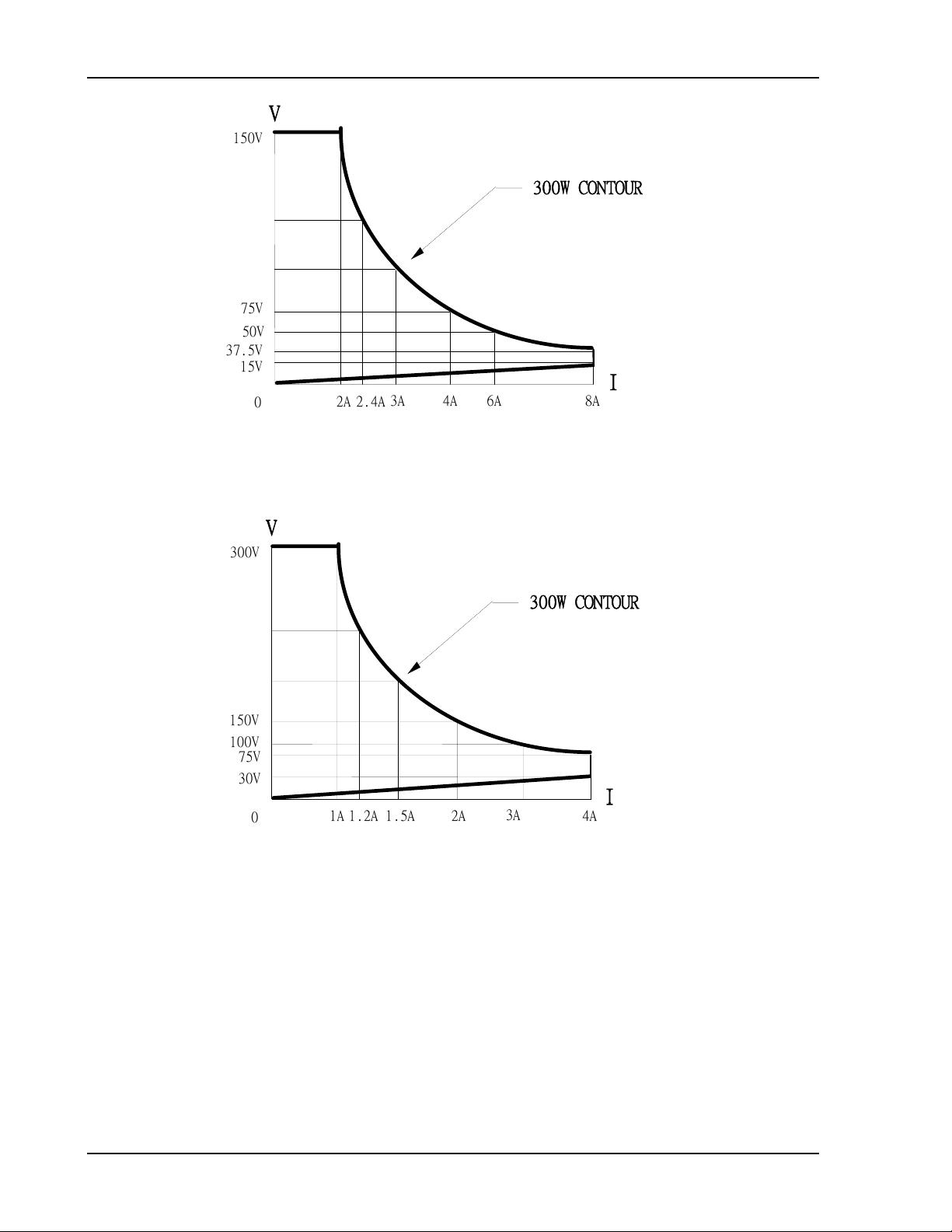
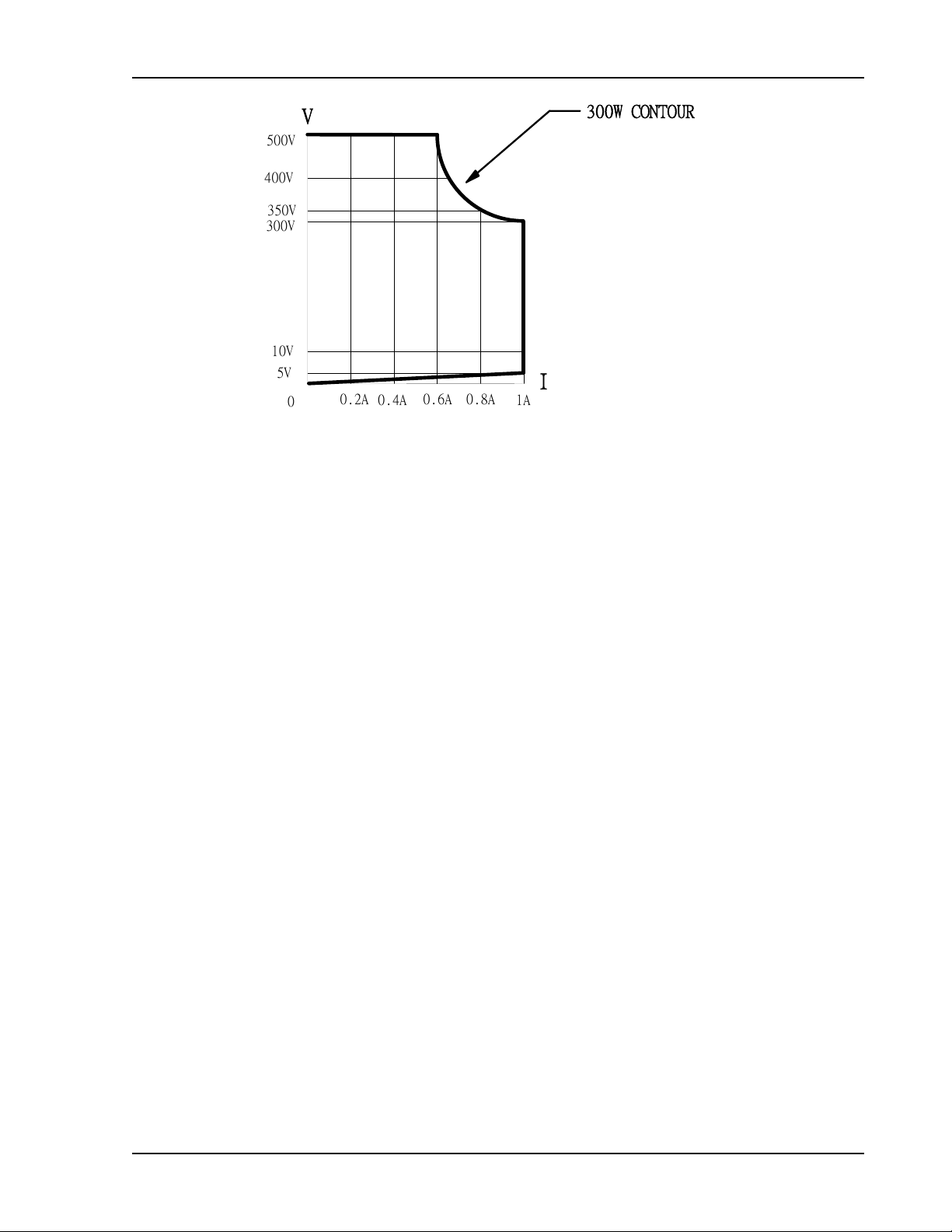
1.1.1 Power Contours
The power contours of the SLM-Series AC/DC Electronic Loads are shown in the
following figures.
V
6
0
50V
40V
30V
15V
10V
5
0
Figure 1-1 SLM-60-20-300 Electronic Load Power Curve
A
300W CONTOU
R
I
7.5
10A
A
15A
6
A
20A
M540072-01 Rev B 1-1
Page 18
Features, Functions, Specifications SLM-Series AC/DC Load
V
150
V
125V
100V
75V
37.5V
15V
50V
300W CONTOU
3
A
4
A
6
2.4
A
2
0
A
A
8
R
I
A
Figure 1-2 SLM-150-8-300 Electronic Load Power Curve
V
300
V
300W CONTOU
R
250V
200V
150
V
100
V
75V
30V
I
3
2
1
A
1.2
A
1.5
0
A
A
Figure 1-3 SLM-300-4-300 Electronic Load Power Curve
A
4
A
1-2 M540072-01 Rev B
Page 19
SLM-Series AC/DC Load Features, Functions, and Specifications
400
500
350
300
10V
V
V
V
V
V
5
V
0.8
0.4
0.6
A
0.2
0
A
A
A
I
1
A
300W CONTOU
R
Figure 1-4 SLM-500-1-300 Electronic Load Power Curve
M540072-01 Rev B 1-3
Page 20
Features, Functions, Specifications SLM-Series AC/DC Load
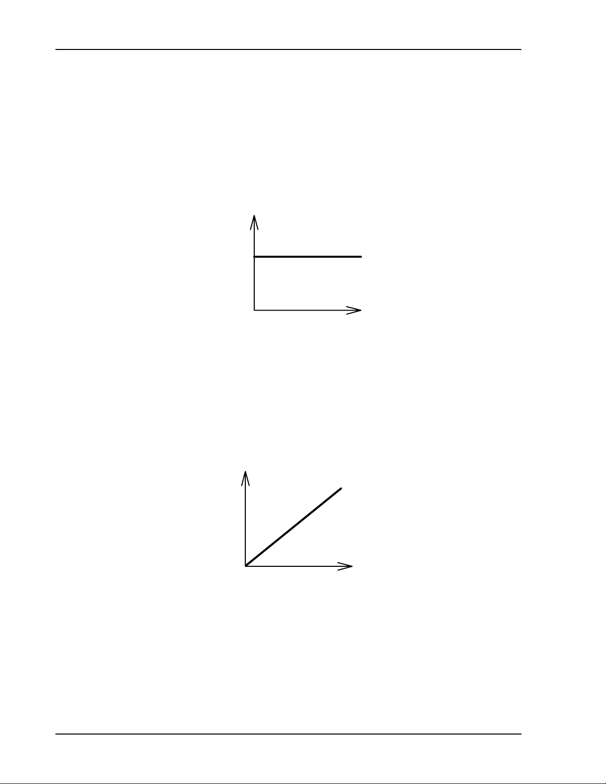
1.1.2 Operating Modes
The work mode of SLM-Series AC/DC Electronic Load includes Constant Current (CC)
and Constant Resistance (CR).
CC Mode
During CC mode, the load current input into SLM-Series, AC Electronic Load
depends on the current setting regardless of the input voltage, i.e., the current
setting remains unchanged.
I
CC
CURRENT SETTING
LOAD
CURRENT
V
INPUT VOLTAGE
Figure 1-5 Characteristics of CC Mode
CR Mode
During C.R. mode, the load current input into SLM-Series AC/DC Electronic Load
depends on the resistance setting. At this time, the load current is in direct
proportion to input voltage, e.g. the resistance setting remains unchanged. Please
refer to Figure 1-6 below.
I
LOAD
CURRENT
RESISTANCE
SETTING
V
INPUT VOLTAGE
Figure 1-6 Characteristics of CR Mode
The load setting of SLM-Series AC/DC Electronic Load and the load condition setting of the
front panel can be made through front panel manual operation or through GPIB commands.
The load voltage and current can be transmitted to the computer through GPIB bus. For
operation of GPIB, please refer to Section 4.
1-4 M540072-01 Rev B
Page 21

SLM-Series AC/DC Load Features, Functions, and Specifications
1.2 FEATURES AND FUNCTIONS
• Modular design facilitates fast and flexible install/uninstall procedures
• Interface function of full GPIB control, including setting of load condition and read-
back of Vmeter and Ameter
• Software calibration ability
• Dual High Accuracy/High Resolution 4 ½ -digit Vmeter and Ameter
• In CC mode, frequency width can reach to 70Hz with the set table range of 1KHz
• In CC mode, the settable Crest Factor can be set to Maximum 3.5
• Isolated Current Monitor BNC output with full scale of 10V
• Automatic judging ability for GO/NG
• Switchable automatic voltage sensing ability.
• Protection functions include Over-Voltage, Over-Current, Over-Power and Over-
Temperature
• Cooling fan control device with revolution change function
1.3 ACCESSORIES
• Vsense Input BNC Connector 1 EA
• Banana Terminal (Black) 1 EA
• Banana Terminal (Red) 1 EA
• Hook-Type Terminal 2 EA
• SLM-Series AC/DC Electronic Load Operation and Programming
Manual (this manual) 1 EA
M540072-01 Rev B 1-5
Page 22
Features, Functions, Specifications SLM-Series AC/DC Load
(VA)
(Amp
)
ge(
)
g
y
g
K
y
g
y
g
y
g
y
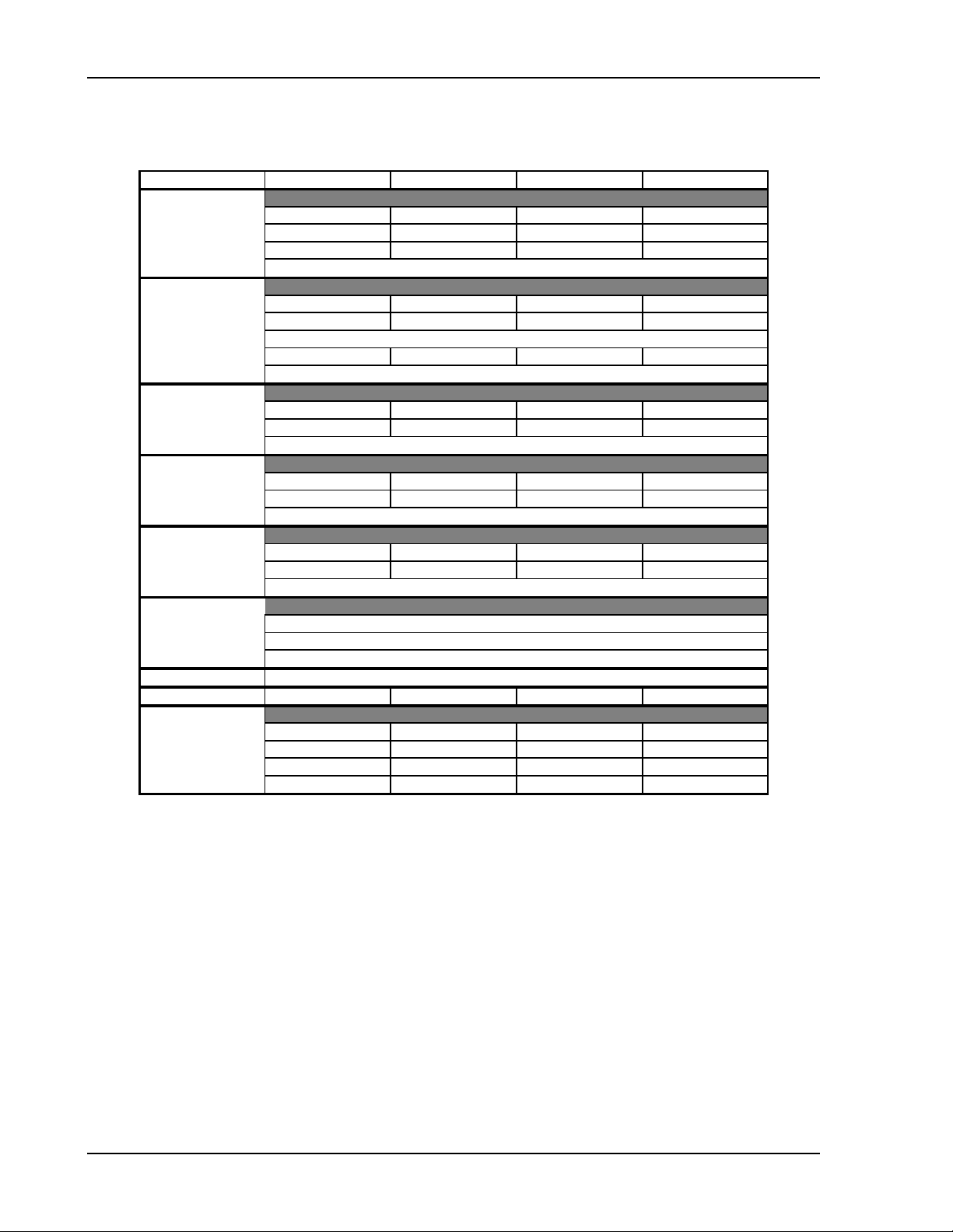
1.4 SPECIFICATIONS
NOTE: The following specifications apply 25°±5°:
MODEL
INPUT RATINGS
Power
Current
Volta
CC MODE
CR MODE
4 1/2 DVM
4 1/2 DAM
4 1/2 WATT METER
VA METER
Imonitor
PROTECTION
Volt
Frequency
Ran
Resolution 2.5 / 5 mA 1 / 2 mA 0.5 / 1 mA 0.125 / 0.25 mA
Accurac
Low current 0 - 1 A 0 - 0.4 A 0 - 0.2 A 0 - 0.05 A
Accuracy ± 2% of (setting + range)
e II/I 0.3-1.2 / 1.2-4.8K 1.875-7.5 / 7.5-30K 7.5-30 / 30-120K50-200 / 200-800
Ran
Resolution 0.83 / 0.2083 mS 0.13 / 0.033 mS 0.033 /0.0083 mS 0.005 / 0.00125 mS
Accurac
Ran
Resolution 0.01 V 0.01 V 0.1 V 0.1 V
Accurac
Ran
Resolution 0.01 A 0.001 A 0.001 A 0.001 A
Accurac
Ran
Resolution
Accurac
OCP ~21 A ~8.4 A ~4.2 A ~1.05 A
OVP ~63 V ~175.5 V ~315 V ~525 V
SLM-60-20-300 SLM-150-8-300 SLM-300-4-300 SLM-500-1-300
300 VA 300 VA 300 VA 300 VA
ere
OPP ~315 VA ~315 VA ~315 VA ~3 15 VA
OTP 85
20 Arms 8 Arms 4 Arms 1 Arms
60 Vrms 150 Vrms 300 Vrms 500Vdc/300 Vrms
DC, 40 - 70Hz (CC Mode) ; DC - 70Hz (CR Mode)
e 0-10 / 10-20 A 0-4 / 4-8 A 0-2 / 2-4 A 0-0.5 / 0.5-1 A
±0.5% of (setting + range)
±0.5% of (setting + range)
e 60 V 150 V 300 V 500 V
±(0.5% of reading + 0.2% of range)
e20 A8 A4 A1 A
±(0.5% of reading + 2% of range) ; ±0.5% of (reading + range) @ 50/60Hz
Vrms×Arms
℃
300 W
0.1 W
85
℃
e
± (0.5% of reading)± 3W
5 A/V 2 A/V 1 A/V 0.2 A/V
℃
85
85
℃
Table 1-1 SLM-Series AC/DCSpecifications
1.5 REGULATORY COMPLIANCE
• Certified to UL 61010-1, CSA C22.2 No. 61010.1 and IEC/EN 61010-1
• CE Compliant:
o Low Voltage Directive (73/23/EEC) using EN 61010-1
o EMC Directive (89/336/EEC) using EN 61326
• FCC Compliant to 21 CFR, Subpart J
1-6 M540072-01 Rev B
Page 23
INSTALLATION AND MAINTENANCE
2.1 INTRODUCTION
This section discusses the installation and removal procedures for the SLM-Series
AC/DC load module and the SLM four-module mainframe. The SLM-Series AC/DC
load module does not need any adjustment after plugging into the SLM mainframe.
SECTION 2
Warning:
Only qualified personnel should do installation and removal.
2.2 INSPECTION
The SLM-Series AC/DC Electronic Load was carefully inspected before shipment. If
instrument damage has occurred during transport, please inform Xantrex sales and
service office or representative.
Unless the SLM mainframe and the SLM-Series AC/DC electronic load module were
purchased separately, the load module should be installed in the mainframe before
shipment from Xantrex. The SLM-Series AC/DC electronic load module operates in
the SLM mainframe for front panel, mainframe's 150 sets store/recall and remote
control feature.
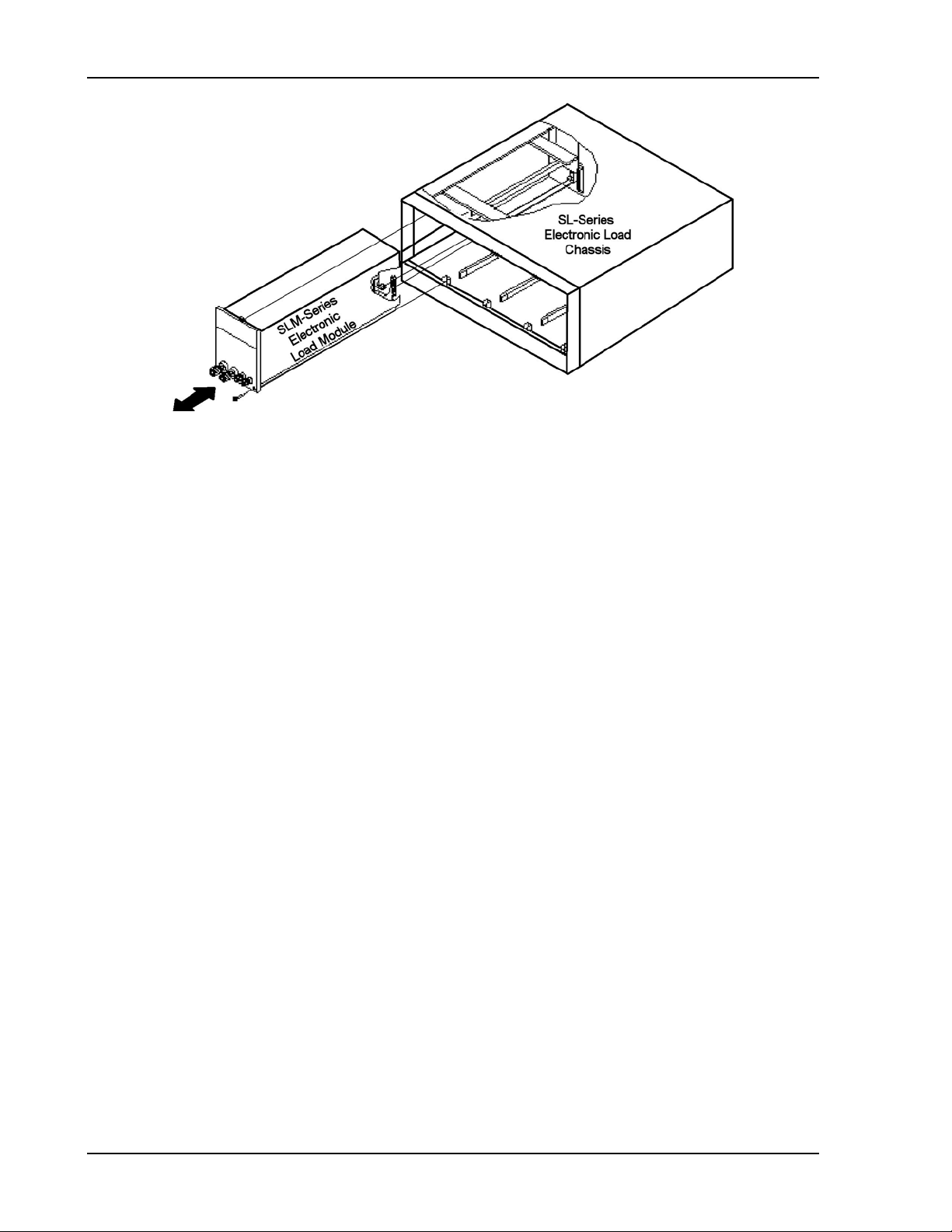
2.2.1 Installation
1 Turn the SLM mainframe power OFF before inserting any load module, or
damage may occur to the plug-in module circuitry.
2. Align the upper and lower grooves of the mainframe with the upper and lower
guides of the selected compartment (Figure 2-1).
3. Push the module in and press firmly on the binding posts of the front panel to
seat the circuit board into the interconnecting jack.
4. Using a screwdriver, tighten the screw on the lower right corner of the SLMSeries load module front panel.
5. DO NOT turn the mainframe power ON until after all of the electronic modules
are completely installed.
M540072-01 Rev B 2-1
Page 24
Installation SLM-Series AC/DC Load
Figure 2-1 Plug-in Installation and Removal
2.2.2 Removal
1. Turn the SLM mainframe power OFF. Damage may occur to the plug-in
module circuitry if removed under power.
2. Using a screwdriver, loosen the screw on the lower right corner of the front panel.
3. Turn the adjustment knob of the black binding post counter-clockwise until it is
fully loosened.
4. Pull on the black adjustment knob of binding post until the interconnecting jack at
the rear of the load module disengages.
5. Finish pulling the SLM-Series load module out from the mainframe.
2.2.3 Environmental Requirements
• For indoor use only
• Installation Category II (over voltage)
• Pollution Degree 2
• Altitude up to 2000 meters (with power derating)
• Relative Humidity 80% RH Max
Ambient Operating Temperature 0-40°C, with ideal being 25°C ± 5°C
2.2.4 Service or Repair
If the instrument is damaged, please attach a tag to the instrument, identifying the
owner and indicating the required service. Follow the procedures detailed on Page iii
of this manual.
2-2 M540072-01 Rev B
Page 25

SLM-Series AC/DC Load Installation
2.3 CONNECTIONS
CAUTION: PREVENT DAMAGE TO THE LOAD. Do NOT apply voltage or current
with power switched OFF. Turn ON the power switch to the load PRIOR to applying
voltage or current to the input terminals (i.e., before turning on the power supply
under test).
2.3.1 Input Binding Post and Wire Considerations
The output of the device under test (DUT) can be connected to the load by one of
five methods, each described in the following subsections. Connect he positive (+)
and negative (-) binding posts to the wires/cables according to the following
guidelines. A major consideration in making input connection is the wire size. The
minimum wire size is required to prevent overheating and to maintain good
regulation. It is recommended that the wires be large enough to limit the voltage
drop to less than 0.5V per lead.
Note: When using Constant Resistance mode, Vsense inputs should be used to
avoid cable resistance from affecting measurements and regulation.
Plug Connectors
This is the most common way to connect the input of electronic load to the device
under test. It is recommended the load current be less than 20A in this
connection since the current rating of the plug is rated to 20A. The maximum wire
gauge should be limited to AWG14.
Hook Terminals
The SLM-Series AC/DC Electronic Load attachments include two (2) hook-type
terminals for connecting the equipment to be measured with the wire of the AC
electronic input connector. The hook terminal provides a good contact to the
binding post and can be used anytime. The maximum wire gauge should be
limited to AWG10.
Direct Insertion into Binding Posts
This is the simplest way to connect the load input to the DUT. The maximum wire
gauge AWG14 can be used in this application.
Plug Connectors and Hook Terminals
This method is recommended when input current is greater than 20A, because it
provides higher current rating and lower impedance of the connecting wire.
Plug Connectors and Direct Insertion
This method is also recommended when input current is greater than 20A or
when the connecting lead wire is longer.
M540072-01 Rev B 2-3
Page 26
Installation SLM-Series AC/DC Load
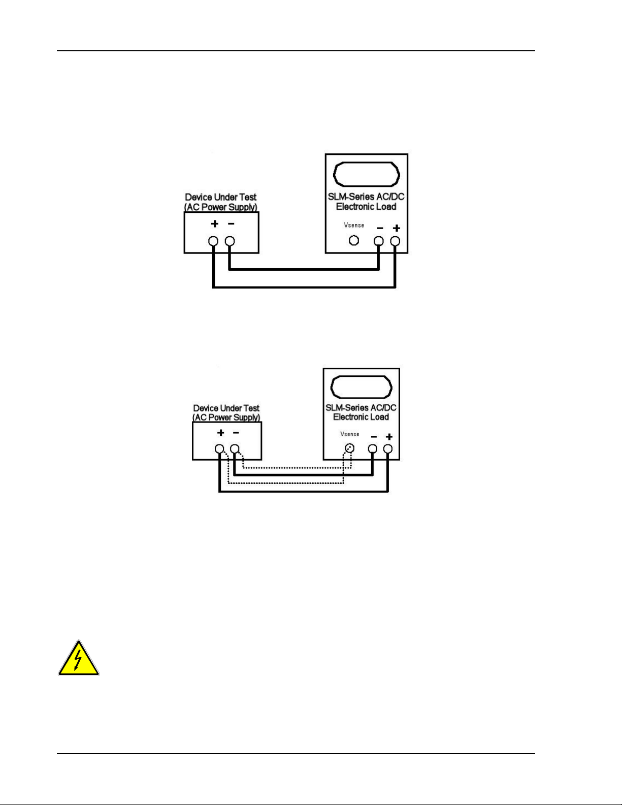
2.3.2 Voltage Sensing Input (Vsense) BNC Connector.
To solve the conductor voltage drop under a big load current, Vsense-CLIP cable
can be used to connect with the specific point to be measured thus obtaining the
specific voltage value. See Figure 2-2 and Figure 2-3.
Figure 2-2 Connection Method for Small Load Current Condition
Figure 2-3 Typical Connection for SLM-Series AC/DC Electronic Load
2.3.3 RS-232C and GPIB Connections
For these connections, refer to the SL-series mainframe operation manual(s).
RS-232 and GPIB programming operation are addressed in Section 4 of this manual.
2.4 MAINTENANCE
WARNING: Avoid electrical shock or damage to the meter.
To avoid electrical shock or damage to the meter, do not get water inside
the case.
Periodically wipe the case with a damp cloth and detergent; do not use abrasives or
solvents.
2-4 M540072-01 Rev B
Page 27
SECTION 3
OPERATION
3.1 FRONT PANEL CONTROLS AND INDICATORS
This section describes the front panel and its manual operation of the SLM-Series
AC/DC Electronic Load. For calibration procedures, please refer to the SLM-Series
Load Calibration Manual. For GPIB control, please refer to Section 4, GPIB Remote
Operation, of this manual.
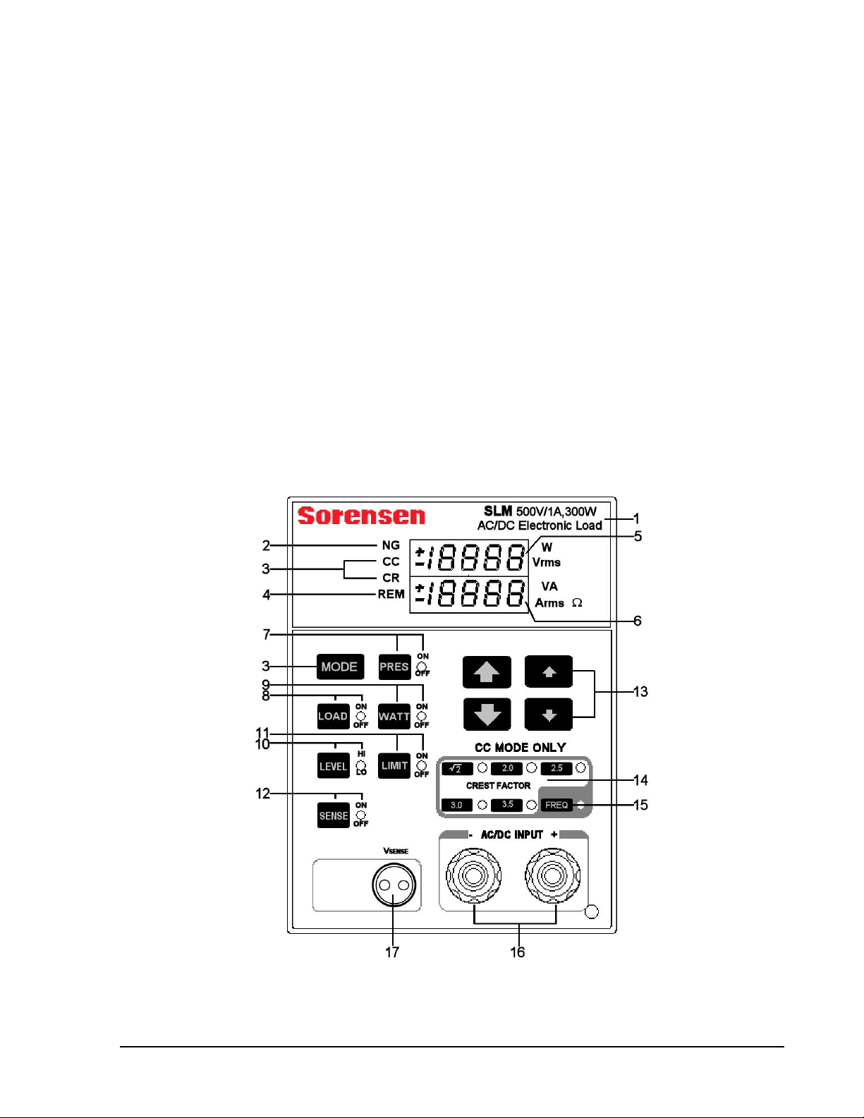
Figure 3-1 Front Panel of SLM-Series AC/DC Electronic Load
M540072-01 Rev B 3-1
Page 28

Operation SLM-Series AC/DC Electronic Load
1 Model Label
Shows load model series and its voltage, current and power specifications.
2 NG LED
• When lit, indicates “No Go” (fail) when Vmeter, Ameter, Wattmeter or VA meter exceeds
the upper or lower limit set.
• When not lit, indicates “Go” (no fail).
3 MODE key and CC, CR LEDs
The MODE key toggles between Constant Current (CC LED on) or Constant Resistance
(CR LED on) operating modes.
4 REM LED
Indicates remote operation:
• When lit, the unit is under remote control and cannot be operated through the front panel
keys. (Remote controller releases control by GPIB command).
• When not lit, the unit is under local control and can be manually operated using the front
panel keys.
5 Upper Digital Meter (DM)
Multi-purpose display, depending on selected mode:
• Under general conditions, functions as a 4 ½ digital voltmeter to display the voltage at
the load input or Vsense BNC input.
• During WATT ON condition, functions as a wattmeter to display the power of the load.
• Under LIMIT ON condition, displays the upper limit of:
o Voltmeter with the unit as “Vrms”.
o Ammeter with the unit as “Arms”.
o Wattmeter with the unit as “W”.
o VA meter with the unit as “VA”.
• During protection condition, displays “oVP” for over-voltage.
• During FREQ ON (see 15) condition, displays:
o “FrEq” (frequency),
o “bAn” (bank), or
o “Sync” (Sync)
6 Lower Digital Meter (DM)
• Under Preset OFF, functions as a 4 ½ digital ammeter to display the load current
actually flowing into the electronic load.
• In Preset ON (see 7) mode, displays the set value whether by front panel manual
operation or by remote control.
• In CC Mode (see 3), displays the set value of CC Level Lo and Hi in “Arms”.
• In CR Mode (see 3), displays the set value of CR Level Lo and Hi in “Ω”.
• During protection condition, displays:
o “oCP” for over-current,
o “oPP” for over-power, or
o “oTP” for over-temperature
• During LIMIT ON condition (see 11), displays the lower limit of:
o Voltmeter with the unit as “Vrms”.
o Ammeter with the unit as “Arms”.
o Wattmeter with the unit as “W”.
o VA meter with the unit as “VA”.
3-2 M540072-01 Rev B
Page 29

SLM-Series AC/DC Electronic Load Operation
• During FREQ ON condition (see 15):
o For frequency (“FrEq”) setting, displays DC, 0.1 - 70.0, Auto.
o For bank (“bAn”) selection, displays 0 - 10.
o For sync (“Sync”) selection, displays “ON”, OFF”.
7 PRES key and ON/OFF LED
Key toggles Preset mode and its LED on and off.
• During Preset OFF, PRES ON/OFF LED not lit:
o upper DM displays the voltage input to electronic load as “Vrms” (Vrms LED lit)
o lower DM displays the current flowing into electronic load as “Arms” (Arms LED
lit)
• During Preset ON, PRES ON/OFF LED lit,
o both upper and lower DMs will have different displays depending on which mode
is active:
Constant Current mode (CC LED on), lower DM displays the setting value
of Level A/B load current as “Arms”, (Arms LED lit).
Constant Resistance mode (CR LED on), lower DM displays the setting
value of Level A/B load resistance as “Ω”, (Ω LED lit).
8 LOAD key and ON/OFF LED
Key toggles Load and its LED on and off.
• Load OFF (LED not lit), electronic load returns to the condition set originally.
• Load ON (LED lit), electronic load is at the condition set originally and is ready to be
loaded with the load current of the AC/DC input power source.
9 WATT key and ON/OFF LED
Key toggles Watt mode and its LED on and off.
• Watt ON (LED lit) indicates the Watt VA condition of actual loading.
• Watt OFF (LED not lit) means Watt OFF, e.g., to indicate the voltage and current
condition of actual loading.
• During Preset OFF (see 7) condition:
o upper DM displays the value in Watts consumed for electronic loading (“W” LED
is lit);
o lower DM displays the value in VA flowing into electronic load (“VA” LED lit).
• During Preset ON (see 7) condition, both upper and lower 4-½ digit monitors will have
different displays with the change of working mode as follows:
o CC Mode, the setting value of Level A/B load current displayed on the lower DM
with the unit as “Arms” and corresponding LED lit.
o CR Mode, the setting value of Level A/B load resistance displayed on the lower
DM with the unit as “Ω” and corresponding LED lit.
10 LEVEL key and Lo/Hi LED
Key toggles between Low, LED off, and Hi, LED ON to set the values of groups A/B for
rapid switching load current or resistance.
11 LIMIT key and ON/OFF LED
Key toggles between Limit ON (LED lit) and Limit OFF (LED not lit) condition:
• Upper DM displays upper limit of:
o Voltmeter with the unit as “Vrms”.
o Ammeter with the unit as “Arms”.
o Wattmeter with the unit as “W”.
M540072-01 Rev B 3-3
Page 30

Operation SLM-Series AC/DC Electronic Load
o VA meter with the unit as “VA”..
• Lower DM displays the lower limit of:
o Voltmeter with the unit as “Vrms”.
o Ammeter with the unit as “Arms”.
o Wattmeter with the unit as “W”.
o VA meter with the unit as “VA”.
(See 13 for upper and lower limit adjustment).
12 SENSE key and ON/OFF LED
Controls whether or not the input to the voltmeter is made from the AC input end (Sense
LED OFF) or from the Vsense end (Sense LED ON). The DM displays the voltage from
either.
13 Load Current Coarse Tuning/Fine Tuning, Increase/Decrease Keys
• During PRESET ON (see 7):
o The larger arrows () coarse tune the value by larger increments/decrements.
o The smaller arrows ( ) fine tune the value by smaller increments/decrements.
• During LIMIT ON (see 11):
o 3.1.13.2.1 :Upper limit value Up/Down Key.
o 3.1.13.2.2 :Lower limit value Up/Down Key.
• When FREQ (see 15) LED lit:
o “FrEq” displayed in upper DM, keys adjust the frequency value by coarse
(larger) increments/decrements, and the keys adjust the frequency value by
fine (smaller) increments/decrements.
o “bAn” displayed in upper DM,: is Fine Tuning Up Key is Fine Tuning
Down Key.
o “Sync” displayed in upper DM, is ON Key is OFF Key.
14 √2, 2.0, 2.5, 3.0, 3.5 keys and their respective LEDs:
Each key only functions in CC mode and has no effect in CR mode.
These keys are selected to change the current C.F. (Peak Factor) of CC mode. When
changing BANK (see 15) settings, these keys will define different C.F. values.
15 FREQ key and LED
Key scrolls from FREQ to BANK to SYNC (displayed in DM) to off (LED not lit).
• Frequency and Bank can only be set in CC MODE
o FREQ (For Frequency Setting) : Setting Range: DC, 0.1 - 70.0 Hz, Auto.
o BANK (For Bank Setting ) : 0 - 10 totaling 11 banks (Not valid for DC).
• SYNC (Current Bank Sync Signal Selection):
o ON is external Sync
o OFF is internal Sync.
16 AC/DC Load Input Connector
Must not exceed the rated specification of the voltage and current of the SLM-Series
AC/DC Electronic Load.
Warning: Upon wiring, please refer to Section 3.2 to avoid damage to internal circuit and
connector.
3-4 M540072-01 Rev B
Page 31

SLM-Series AC/DC Electronic Load Operation
17 Vsense BNC, Voltage Sensing Input BNC Connector.
To solve the conductor voltage drop under a big load current, Vsense-CLIP cable can be
used to connect with the specific point to be measured thus obtaining the specific voltage
value.
The control keys are summarized in Figure 3-2.
SLM AC Loads
Button Functions
MODE
CC: Constant Current
CR: Constant Resistance
SENSE
ON: Vsense input voltage
OFF: Input terminal voltage
PRESet
ON
OFF
WATT
ON: Watt Displayed
on Upper Monitor
VA Displayed
on Lower Monitor
OFF: Vrms Displayed
on Upper Monitor
Arms Displayed
on Lower Monitor
LIMIT
FREQ
Figure 3-2 Front Panel Button Functions for SLM-Series AC/DC Unit
3.2 SET-UP PROCEDURES
The following set up procedures are summarized in the flow chart in Figure 3-4.
3.2.1 Pass / Fail Limits, Go/No GO Limits
G/NG RMS Volt Limits
G/NG RMS Current Limits
G/NG Power Limits [W]
G/NG Power Limits [VA]
FREQ
Frequency Setting
Bank
Crest factor
bank setting
Sync
LEVEL
HIGH
LOW
LOAD
ON
OFF
(If pass/fail limits are not desired, skip to Frequency Setting below).
The limits set the value range within which the inputs must fall for the NG LED to
remain off and sets the NG register to 0 (pass) or 1 (fail).
Voltage:
Press the LIMIT key until the LIMIT LED is on and the “Vrms” LED (5) is lit. The
upper digital meter (DM) displays the upper voltage limit; the lower DM displays
the lower voltage limit. Use the coarse
keys to set the upper limit and the
fine ↑↓ keys to set the lower limit.
Current:
Press the LIMIT key until the LIMIT LED is on and the “Arms” LED (5) is lit. The
upper DM displays the upper current limit; the lower 5-digit display shows the
lower current limit. Use the coarse keys to set the upper limit and the fine
↑↓ keys to set the lower limit.
M540072-01 Rev B 3-5
Page 32

Operation SLM-Series AC/DC Electronic Load
Power:
Press the LIMIT key until the LIMIT LED is on and the “W” LED (5) is lit. The
upper DM displays the upper power limit; the lower DM displays the lower power
limit. Use the coarse keys to set the upper limit and the fine ↑↓ keys to set
the lower limit.
VA:
Press the LIMIT key until the LIMIT LED is on and the “VA” LED (5) is lit. The
upper DM displays the upper VA limit; the lower DM displays the lower VA limit.
Use the coarse
limit.
Vsense Input: The “SENSE” key toggles external Vsense on (LED lit) and off (LED
not lit).
to set the upper limit and the fine ↑↓ keys to set the lower
3.2.2 Frequency Setting:
The range for setting the frequency of SLM-Series AC/DC electronic Load module is
from DC-70Hz. Specifications apply 40-70Hz.
1. Press the FREQ key (15) until its LED lights and “FrEq” appears on the upper
DM.
2. Use the coarse/fine
or to Auto.
• If the frequency setting is less than 0.1 Hz, the frequency setting value will
set automatically to DC.
• In Auto, the load automatically synchronizes to the zero crossing of the
voltage input at the terminals.
• After setting the frequency, set the SYNC trigger to OFF to make the
frequency valid.
/↑↓ keys to set the frequency to the desired value, to DC
3.2.3 Current Synchronization
External SYNC Signal (SYNC ON)
• The user can input a SYNC signal to the Analog Programming Input BNC
connector on the back plate.
• Based on this external SYNC signal, the SLM-Series AC/DC Electronic Load,
the phase of load current will synchronize to the zero crossing of the external
signal.
• The external SYNC signal must be a 50% duty cycle.
1. Press the “FREQ” key until “Sync” appears on the upper DM.
2. Press any
Internal SYNC signal (SYNC OFF)
• The internal SYNC signal source of SLM-Series AC/DC electronic load is
taken from the voltage signal at the terminal inputs.
• The load current signal will synchronize to the voltage zero crossing of the
input terminals.
3-6 M540072-01 Rev B
↑↓ key to toggle the external sync on and off.
Page 33

SLM-Series AC/DC Electronic Load Operation
EXT+
EXT-
3.2.4 Crest Factor
The SLM-Series AC/DC electronic load module provides 11 built-in sets totaling 55
waveforms.
• Select the waveforms from the memory banks. The waveforms are stored in
memory banks (0-10) with 5 selections per bank as shown in Table 3-1. (See
Appendix for waveform details).
• Select the crest factor through the √2, 2.0, 2.5, 3.0 and 3.5 keys in addition
to the bank selection.
Sine Wave
1 1.5 1.6 1.7 1.8 1.9
2 2.0 2.1 2.2 2.3 2.4
3 2.5 2.6 2.7 2.8 2.9
4 3.0 3.1 3.2 3.3 3.4
Square Wave 5 1.0 1.1 1.2 1.3 1.4
6 1.5 1.6 1.7 1.8 1.9
7 2.0 2.1 2.2 2.3 2.4
8 2.5 2.6 2.7 2.8 2.9
9 3.0 3.1 3.2 3.3 3.4
DC 10 √2dc 2dc 2.5dc 3.0dc 3.5dc
BANK √2 2.0 2.5 3.0 3.5
Input
Zero Crossing
SYNC "OFF"
330Ω
SYNC "ON"
+5V
SYNC
SYNC
Figure 3-3 Illustration of Sync
0 √2 2.0 2.5 3.0 3.5
Table 3-1 Built in Crest Factor Settings by Bank andKkey Selection
• When Frequency is set to DC (see Frequency Setting above), the waveform
information shall be fixed at DC level and the “bAn” bank selection will not
appear in the FREQ key menu.
1. Press FREQ key (15). The associated LED will light. The first selection is for
frequency, as described in the section, “Frequency Setting” above.
2. Verify that the frequency does not read “dc”. If it does, use the ↑↓ keys to
adjust the frequency from “dc”.
3. Press the “FREQ” key until “bAn” appears on the upper DM.
4. Use the ↑↓ keys to select the desired bank.
M540072-01 Rev B 3-7
Page 34

Operation SLM-Series AC/DC Electronic Load
5. Press the “FREQ” key two times to exit setting mode.
6. Press the appropriate √2, 2.0, 2.5, 3.0 and 3.5 keys to select the desired
crest factor. The associated LED will light.
3.2.5 Display Setting
In normal operation, the DMs display RMS voltage and RMS current.
• To display power in Watts (upper DM) and VA (lower DM), press the “WATT”
key until the associated LED (W or VA) is lit.
• To return to normal display mode, press the “WATT” key again.
3-8 M540072-01 Rev B
Page 35

SLM-Series AC/DC Electronic Load Operation
DESCRIPTION DISPLAY CONTROL
LIMIT
Set
G/NG Voltage
Limits
Set
G/NG Current
Limits
Set
G/NG Power
Limits
Set
G/NG VA
Limits
SENSE
FREQ
Set frequency.
MIN=dc,
Max.=Auto
LED ON: VRMS, LIMIT
Upper 4½-digit: Upper
Limit Setting
Lower 4½-digit: Lower
Limit Setting
LED ON: ARMS, LIMIT
Upper 4½-digit: Upper
Limit Setting
Lower 4½-digit: Lower
Limit Setting
LED ON: W, LIMIT
Upper 4½-digit: Upper
Limit Setting
Lower 4½-digit: Lower
Limit Setting
LED ON: VA, LIMIT
Upper 4½-digit: Upper
Limit Setting
Lower 4½-digit: Lower
Limit Setting
LEDs ON: SENSE
LED ON: FREQ
Upper 4½-digit: "FrEq"
Lower 4½-digit: dc,
frequency setting, auto
Sets upper limit
↑↓ Sets lower limit
Sets upper limit
↑↓ Sets lower limit
Sets upper limit
↑↓ Sets lower limit
Sets upper limit
↑↓ Sets lower limit
↑↓
Any setting button
toggles sense on/off
↑↓
Course/fine setting
Set BANK Number
for Crest Factor
Waveform
Set SYNC source
ON=External
OFF=Input Terminal
or Vsense
WATT
Setup Complete
LED ON: FREQ
Upper 4½-digit: "bAn"
Lower 4½-digit: Bank
number setting 0-10
LED ON: FREQ
Upper 4½-digit: "Sync"
Lower 4½-digit: On/off
LED ON: WATT
Upper 4½-digit: "W"
Lower 4½-digit: "VA"
↑ ↓
High Bank# / Lower
Bank#
↑↓
Any button
toggles on/off
↑↓
Any button
toggles on/off
Figure 3-4 SLM-Series AC/DC Electronic Load Module Setup Flow Chart
M540072-01 Rev B 3-9
Page 36

Operation SLM-Series AC/DC Electronic Load
3.3 NORMAL OPERATION
3.3.1 CC Mode:
Two levels can be set to allow for quick switching between two current levels. One
crest factor setting (see Crest Factor Selection next) applies to both levels. Although
the levels are referenced “high” and “low,” the setting level does not require one to
be higher than the other.
1. Press the MODE button (3), until the CC LED (3) is lit.
2. Press the PRES button (7) to view the programmed values. The load has a high
and low setting to allow for quick changes in load setting.
a. To set the low level, press the LEVEL button (10) until the associated
LED is not lit (or do not press the button if the load is already in low state).
Use the ↑↓ buttons (13) to adjust to the desired level.
b. To set the high level, press the LEVEL button until the associated LED is
lit (or do not press the button if the load is already in high state). Use the
↑↓ buttons to set the desired level.
3. To exit the preset mode, press the PRES button until the associated LED turns
3.3.2 Crest Factor Selection:
The SLM Series AC/DC electronic load module provides 11 built-in sets totaling 55
waveforms. The waveforms are stored in memory banks (0-10) with 5 selections per
bank as shown in Table 3-1. Please refer to Appendix for details of waveforms.
When Frequency is set to DC (see Frequency section above), the waveform
information shall be fixed at DC level and the “bAn” bank selection will not appear in
the FREQ button menu.
1. Press FREQ button (15). The associated LED will light. Verify that the
frequency does not read “dc”. If it does, use the ↑↓ buttons to adjust the
frequency from “dc”.
2. Press the “FREQ” button until “bAn” appears on the upper display.
3. Use the
4. Press the “FREQ” button two times to exit setting mode.
5. Press the appropriate √2, 2.0, 2.5, 3.0 and 3.5 key to select the desired crest
factor. The associated LED will light.
6. Press the LEVEL key to select the desired level CC mode. When the LED is
lit, the HIGH level is selected and when unlit, the LOW level is selected.
7. Press the LOAD button (8) to toggle the load off or on.
↑↓ buttons to select the desired bank, as defined in Table 3-1.
• Press the LEVEL button at any time to switch between the settings.
• Use the
• Press the PRES key to view the set values.
3-10 M540072-01 Rev B
↑↓ keys any time to change the current.
Page 37

SLM-Series AC/DC Electronic Load Operation
3.3.3 CR Mode
Two levels can be set to allow for quick switching between two current levels. One
crest factor setting (see section 3-2) applies to both levels. Although the levels are
referenced “high” and “low,” the setting level does not require one to be higher than
the other.
In CR mode, the value setting is inverse to the increment/decrement arrows; i.e., the
↑ keys decrease the resistance setting, and the ↓ keys increase the resistance
setting.
1. Press the MODE button, until the CR LED is lit (3).
2. Press the PRES button (7) to view the programmed values.
a. To set the low level, press the LEVEL button (10) until the associated
LED is not lit (or do not press the button if the load is already in low
state). Use the ↑↓ buttons (13) to adjust to the desired level.
b. To set the high level, press the LEVEL button until the associated LED is
lit (or do not press the button if the load is already in high state). Use the
↑↓ buttons to set the desired level.
c. To exit the preset mode, press the PRES button until the LED is no
longer lit.
3. Select the desired CR level by pressing the LEVEL button (10). When the
LED is lit, the HIGH level is selected and when unlit, the LOW level is
selected.
4. Press the LOAD button (8) to toggle the load off or on
• Press the LEVEL button at any time to switch between the settings.
• Use the
• Press the PRES key to view the set values.
↑↓ keys any time to change the resistance.
M540072-01 Rev B 3-11
Page 38

Operation SLM-Series AC/DC Electronic Load
Normal Operating
Modes
Press MODE
Button until desired
mode is illuminated
CC, CR
MODE
Toggle PRESet
viewing off
(LED off )
Toggle between
HIGH (amber LED)
and LOW (LED off)
Preset desired
values
Set LO level
Activate and Set HI
level
PRES
LEVEL
NO
PRES
↑↓
Course/fine setting
LEVEL
↑↓
Course/fine setting
CC Mode?
YES
FREQ
Set FREQ
DC, AC 0.1-70,
Auto
FREQ
Set BANK Number
for Crest Factor
Waveform
FREQ
↑↓
Course/fine setting
↑ ↓
High Bank# / Lower
Bank#
Turn load ON
(LED ON/amber)
Turn load off
(LED off)
Set SYNC source
ON=External
OFF=Input Terminal
or Vsense
FREQ
LOAD
LOAD
↑↓
Any button
toggles sense on/off
Exit FREQ/BANK/
SYNC Setup
Figure 3-5 SLM-Series AC/DC Electronic Load Operation Flow Char
3-12 M540072-01 Rev B
Page 39

SLM-Series AC/DC Electronic Load Operation
3.4 INITIAL SETTINGS OF SLM-SERIES AC/DC ELECTRONIC
LOAD
The initial setting parameters of SLM-Series AC/DC Electronic Load are described in
Table 3-2.
Description
MODE
LOAD OFF OFF OFF OFF
LEVEL LO LO LO LO
SENSE OFF OFF OFF OFF
PRES OFF OFF OFF OFF
WATT OFF OFF OFF OFF
LIMITS
V LIMIT High [VRMS] 100.0 200.0 400.0 600.0
ALIMIT High [ARMS] 25.00 10.00 5.000 2.000
WLIMIT High [W] 400.0 400.0 400.0 400.0
VALIMIT High [VA] 400.0 400.0 400.0 400.0
All Lower Limits 0.00 0.0 0.0 0.0
C.F
FREQ [Hz] 60 60 60 60
BANK 0 0 0 0
SYNC OFF OFF OFF OFF
CC Level LO [ARMS] 0.000 0.000 0.000 0.000
CC Level HI [ARMS] 0.000 0.000 0.000 0.000
CR Level LO [Ω]
CR Level HI [Ω]
SLM-60-20-300 SLM-150-8-300 SLM-300-4-300 SLM-500-1-300
CC CC CC CC
√2 √2 √2 √2
4800 30E3
4800 30E3
120E3 80E3
120E3 80E3
Table 3-3Table 3-2 SLM-Series AC/DC Electronic Load Initial Settings
Last Setting
All SLM-Series AC/DC Electronic Loads retain the last settings used prior to
powering down, so that those same settings are still set at next power-on.
Reset
If the Load’s memory data have been damaged in some way, for example, due to
unstable power source or noises, there may be an error, such as the display
screen showing something different from the actual condition. The Reset
function corrects the errors.
To reset the SLM-Series AC/DC Electronic Load, simultaneously press the
SENSE and the PRES keys. The front panel monitor will display firmware
version and initialize the setting parameters of SLM-Series AC/DC Electronic
Load as shown in Table 3-2 until the key is released.
M540072-01 Rev B 3-13
Page 40

Operation SLM-Series AC/DC Electronic Load
Description
MODE
LOAD OFF OFF OFF OFF
LEVEL LO LO LO LO
SENSE OFF OFF OFF OFF
PRES OFF OFF OFF OFF
WATT OFF OFF OFF OFF
LIMITS
V LIMIT High [VRMS] 100.0 200.0 400.0 600.0
ALIMIT High [ARMS] 25.00 10.00 5.000 2.000
WLIMIT High [W] 400.0 400.0 400.0 400.0
VALIMIT High [VA] 400.0 400.0 400.0 400.0
All Lower Limits 0.00 0.0 0.0 0.0
C.F
FREQ [Hz] 60 60 60 60
BANK 0 0 0 0
SYNC OFF OFF OFF OFF
CC Level LO [ARMS] 0.000 0.000 0.000 0.000
CC Level HI [ARMS] 0.000 0.000 0.000 0.000
CR Level LO [Ω]
CR Level HI [Ω]
SLM-60-20-300 SLM-150-8-300 SLM-300-4-300 SLM-500-1-300
CC CC CC CC
√2 √2 √2 √2
4800 30E3
4800 30E3
120E3 80E3
120E3 80E3
Table 3-3 SLM Series AC/DC Module Factory/Reset Settings
3.4.2 Load current course/fine increase/decrease adjustment key
The maximum load current of the SLM-Series AC/DC Electronic Load Modules can
be adjusted to 20.00A, 8.000A, 4.000A, or 1.000A, as depicted in Table 3-4.
The relationship between the adjustment variation of the load current or resolution
and their keys is also shown in Table 3-4. Pressing and holding any of the arrow
keys for more than one second, speeds the rate of changing the selected value.
SLM-60-20-300
FULL SCALE LOAD CURRENT 10 A 20 A
CURRENT RANGE 20.00 A
METER RESOLUTION 0.01 A
COURSE/FINE LOAD
CURRENT ADJUSTMENT KEY
CC Mode 25 mA 2.5 mA 50 mA 5 mA
CR Mode 2.083mS 0.208mS 8.333mS 0.833mS
SLM-150-8-300
FULL SCALE LOAD CURRENT 4 A 8 A
CURRENT RANGE 8.000 A
METER RESOLUTION 0.001 A
COURSE/FINE LOAD
CURRENT ADJUSTMENT KEY
CC Mode 10 mA 1 mA 20 mA 2 mA
CR Mode 0.333mS 0.033mS 1.333mS 0.133mS
Range 1 Range 2
↑↓
Range 1 Range 2
↑↓
↑↓
↑↓
3-14 M540072-01 Rev B
Page 41

SLM-Series AC/DC Electronic Load Operation
SLM-300-4-300
FULL SCALE LOAD CURRENT 2 A 4 A
CURRENT RANGE 4.000 A
METER RESOLUTION 0.001 A
COURSE/FINE LOAD
CURRENT ADJUSTMENT KEY
CC Mode 5 mA 0.5 mA 10 mA 1 mA
CR Mode 0.083mS 0.008mS 0.333mS 0.033mS
SLM-500-1-300
FULL SCALE LOAD CURRENT 0.5 A 1 A
CURRENT RANGE 1.000 A
METER RESOLUTION 0.001 A
COURSE/FINE LOAD
CURRENT ADJUSTMENT KEY
CC Mode 1.25 mA 0.125 mA 2.5 mA 0.25 mA
CR Mode 0.013mS 0.001mS 0.050mS 0.005mS
Table 3-4 Range, Resolution, andCoarse/Fine and Increment/Decrement Values
Range 1 Range 2
↑↓
Range 1 Range 2
↑↓
↑↓
↑↓
3.5 PROTECTION FEATURES
There are four protection functions for the SLM-Series Electronic Load: Over-Voltage,
Over-Current, Over-Power and Over-Temperature. When the electronic load exceeds
the normal work area range, one of these four functions will activate. This feature turns
OFF the load to protect it from damage. The lower digital meter flashes the protection
status notice, indicating which protection function is active.
3.5.1 Over Voltage Protection (OVP)
The over voltage protection (OVP) point is preset in the SLM-Series AC/DC
Electronic load. Table 3-5 shows the OVP trip values for the various models in the
series. When OVP occurs, the lower digital meter (DM) flashes "oVP". Once the
over voltage condition is reset, the lower DM resumes normal display.
3.5.2 Over Current Protection (OCP)
The over current protection (OCP) point is preset in the SLM-Series AC/DC
Electronic load. Table 3-5 shows the OCP trip values for the various models in the
series. When OCP occurs, the lower digital meter (DM) flashes "oCP". Once the
over current condition is reset, the lower DM resumes normal display.
3.5.3 Over Power Protection (OPP)
The over power protection (OPP) point is preset in the SLM-Series AC/DC Electronic
load. Table 3-5 shows the OPP trip values for the various models in the series.
When OPP occurs, the lower digital meter (DM) flashes "oPP". Once the over power
condition is reset, the lower DM resumes normal display.
M540072-01 Rev B 3-15
Page 42

Operation SLM-Series AC/DC Electronic Load
3.5.4 Over Temperature Protection (OTP)
SLM-Series AC/DC Electronic load is provided with a temperature sensor. Over
temperature protection (OTP) is tripped when the heat dissipater temperature
exceeds about 85ºC ±5ºC, and the lower DM flashes “oTP”. Once the over
temperature condition is reset, the lower DM resumes normal display.
When OTP occurs, check the ambient working temperature and ventilation. The air
outlet on requires a distance of greater than 6 in / 15 cm from any obstruction, for
proper ventilation.
Model OVP
SLH-500-4-1200
SLH-500-6-1800
SLH-300-12-1200
SLH-300-12-1800
SLH-300-18-1800
525.0 V
525.0 V
315.0 V
315.0 V
315.0 V
Table 3-5 SLH AC-series Protection Setting Values
OCP
4.20 A
6.30 A
12.60 A
12.60 A
18.90 A
OPP
1260 VA
1890 VA
1260 VA
1890 VA
1890 VA
3-16 M540072-01 Rev B
Page 43

GPIB/RS-232 PROGRAMMING
4.1 INTRODUCTION
The rear panel of the SLM chassis is designed to connect with a PC (Personal
Computer) or NOTEBOOK PC through GPIB or RS-232 interfaces.
SECTION 4
OPERATION
4.2 GPIB COMMANDS
The following GPIB setting commands are channel-dependent, except the "CHAN"
command, which is channel-specific; therefore, for proper testing program execution,
the channel-specific command "CHAN" should be sent first, followed by the channel-
dependent command.
Example:
Short ON of channel 1 of SLM-Series Electronic Load module, the GPIB
programming command is: CHAN 1:SHOR ON.
The following GPIB commands with [GLOB:] option can set all the SL-series load
modules in the SLM chassis to be active simultaneously. This feature can greatly
reduce the testing time and increase efficiency.
4.3 RS-232 INTERFACE AND COMMANDS
The following RS-232 commands are the same as GPIB commands. The RS-232
protocol in SLM chassis is listed as follows:
B
AUD-RATE 9600
Parity none
Data bit 8 bits
Stop bit 1 bit
Command delay time 20 msec.
M540072-01 Rev B 4-1
Page 44

GPIB/RS-232 Programming Operation SLM-Series AC/DC Electronic Load
The connections for the rear panel RS-232 interface are shown below; Figure 4-1a
depicts the connector wire diagram, and Figure 4-1b depicts the connections using a
standard RS-232 cable.
Inside the
Inside the
SLM Mainframe
SLM Mainframe
2
2
TxD
TxD
3
3
Rxd
Rxd
4
4
RTS
RTS
5
5
CTS
CTS
6
6
DSR
DSR
7
7
GRN
GRN
8
8
DCD
DCD
9
9
DTR
DTR
Fig. 4.1a
Fig. 4.1a
Figure 4-1 RS-232 Interface Diagram
RS-232C Port
RS-232C Port
On SLM Mai nframe
On SLM Mai nframe
TxD
TxD
Rxd
Rxd
RTS
RTS
CTS
CTS
.
.
.
.
.
.
Fig. 4.1b
Fig. 4.1b
PC RS-232C Port
PC RS-232C Port
TxD
TxD
Rxd
Rxd
RTS
RTS
CTS
CTS
.
.
.
.
.
.
The following RS-232 setting commands are channel-dependent commands except
”CHAN” which is a channel-specific command; therefore, for proper program execution
”CHAN” should be sent first, and then the channel-dependent command.
For example:
Short ON of Channel 1 of SL-series Electronic Load module, the RS-232
programming command is: CHAN 1;SHOR ON.
As with the GPIB commands, the following RS-232 commands with [GLOB:] option
can set all the SL-series Electronic load modules in the SLM chassis to be active
simultaneously. This feature can greatly reduce the testing time and increase
efficiency.
4.4 GPIB/RS-232C COMMAND LIST
4.4.1 Command Syntax Abbreviations
SP :Space, the ASCII code is 20 Hexadecimal.
; :Semicolon, Program line terminator, the ASCII code is OA Hexadecimal.
NL :New line, Program line terminator, the ASCII code is OA Hexadecimal.
N :Integer from 1 to 8.
NR2 :Digits with decimal point. It can be accepted in the range and format of ##.#####.
Example: 30.12345, 5.0
4-2 M540072-01 Rev B
Page 45

SLM-Series AC/DC Electronic Load GPIB/RS-232 Programming Operation
Description of GPIB Programming Command Syntax.
{ } :The contents of the { } symbol must be used as a part or data of the
GPIB command, it can not be omitted.
[ ] :The contents of the [ ] symbol indicates that the command is optional,
depending on the testing application.
| :This symbol means to make a choice between one or the other. For
example “HIGH|LOW” means it can only use HIGH or LOW as the
command, but one of the choices must be used.
Terminator :The program line terminator character must be sent after the GPIB
command; the available command terminator characters that can be
accepted in the SLM chassis are listed in Table 4-1.
LF
LF WITH EOI
CR, LF
CR, LF WITH EOI
Table 4-1 GPIB Command Terminator
A terminator informs GPIB that it has reached the end of statement.
Normally, this is sent automatically by your GPIB programming
statements. In this manual, the terminator is assumed at the end of
each example line of code. If it needs to be indicated, it is shown by
symbol (nl); which stand for “new line” and represents ASCII code byte
the OA Hexadecimal or 10 decimal.
Semicolon ”;“ :The semicolon “;” is a back-up command, the semicolon allows you to
combine command statements on one line to create command
message.
Table 4-2 presents a summary of the GPIB/RS-232 Setting commands, and Table 4-3
summarizes the GPIB/RS-232 preset Query commands with applicable module types. Table
4-4 is a summary of State commands, the System commands are in Table 4-5, Measure and
Limit commands are in Table 4-6, and the Global commands are in Table 4-7.
M540072-01 Rev B 4-3
Page 46

GPIB/RS-232 Programming Operation SLM-Series AC/DC Electronic Load
Setting Preset Numeric Command Model Remark
[PRESet:] BANK{SP}{d}{;|NL}
[PRESet:] WAVE{SP}{m}{;|NL }
[PRESet:] FREQuency{SP}{NR2}{;|NL}
[PRESet:] RISE{SP}{NR2}{;|NL} •
[PRESet:] FALL{SP}{NR2}{;|NL} •
[PRESet:] SLEWrate{SP}{NR2}{;|NL}
[PRESet:] PERIod:{HIGH|LOW}{SP}{NR2}{;|NL} • •
[PRESet:] LDONv{SP}{NR2}{;|NL} • •
[PRESet:] LDOFfv{SP}{NR2}{;|NL} • •
[PRESet:] CC{SP}{NR2}{;|NL}
[PRESet:] CC:{A|B}{SP}{NR2}{;|NL}
[PRESet:] CC:{HIGH|LOW}{SP}{NR2}{;|NL} • •
[PRESet:] CP:{HIGH|LOW}{SP}{NR2}{;|NL} •
[PRESet:] CR{SP}{NR2}{;|NL}
[PRESet:] CR:{A|B}{SP}{NR2}{;|NL}
[PRESet:] CR:{HIGH|LOW}{SP}{NR2}{;|NL} •
[PRESet:] CV:{HIGH|LOW} {SP} {NR2}{;|NL} •
[PRESet:] CV{SP}{NR2}{;|NL}
SLM DC SLD SLM AC
•
•
•
•
•
•
•
•
•
d=0~30
M=0~5
40.0~70.0Hz
Table 4-2 GPIB/RS-232 Setting Command Summary
Query Preset Numeric Command Model RETURN
[PRESet:] BANK{SP}{?}{;|NL}
[PRESet:] WAVE{SP}{?}{;|NL}
[PRESet:] FREQuency{?}{;|NL}
[PRESet:] RISE{?}{;|NL} •
[PRESet:] FALL{?}{NR2}{;|NL} •
[PRESet:] SLEWrate{?}{;|NL}
[PRESet:] PeRIod:{HIGH|LOW}{?}{;|NL} • •
[PRESet:] LDONv{?}{;|NL} • •
(PRESet:] LDOFfv{?}{;|NL}
(PRESet:] CC{?}{{;|NL}
(PRESet:] CC:(A|B){?}{;|NL}
(PRESet:] CC:{HIGH|LOW}{?}{;|NL}
(PRESet: CP:{HIGH|LOW}{?}{;|NL}
[PRESet:] CR{?}{;|NL}
[PRESet:] CR:{A|B}{?}{;|NL}
[PRESet:] CR:{HIGH|LOW}{?}{;|NL} • •
[PRESet:] CV:{HIGH|LOW}{?}{;|NL} •
[PRESet:] CV{?}{;|NL}
SLM DC SLD SLM AC
• •
• •
•
###.####
###.####
•
•
###.####
•
###.####
•
•
•
•
###.####
###.####
###.####
###.####
###.####
•
###.####
###.####
•
###.####
###.####
0~10
1~5
40.0~70.0
###.####
###.####
Table 4-3 GPIB/RS-232 Preset Query Command Summary with Applicable Module Types
4-4 M540072-01 Rev B
Page 47

SLM-Series AC/DC Electronic Load GPIB/RS-232 Programming Operation
STATE Command Model RETURN
SLM DC SLD SLM AC
[STATe:] LOAD{SP}{ON|OFF}{;|NL}
• • •
[STATe:] LOAD{?}{;|NL}
[STATe:] MODE{SP}{CC|CR|CV|CP}{;|NL}
[STATe:] MODE{?}{;|NL}
[STATe:] SHORt{SP}{ON|OFF}{;|NL}
[STATe:] SHORt{?}{;|NL}
[STATe:] PRESet{SP}{ON|OFF}{;|NL}
[STATe:] PRESe{?}{;|NL}
[STATe:] SENSe{SP}{ON|OFF}{;|NL}
[STATe:] SENSe{?}{;|NL}
[STATe:] RANGe{SP}{1|2}{;|NL}
[STATe:] RANGe{?}{;|NL}
[STATe:] LEVEl{SP}{HIG|LOW|AIB}{;|NL}
[STATe:] LEVEl{?}{;|NL}
[STATe:] DYNamic{SP}{ON|OFF}{;|NL}
[STATe:] DYNamic{?}{;|NL}
[STATe:] SYNCronize{SP}{ON|OFF}{;|NL}
[STATe:] SYNCronize{?}{;|NL}
[STATe:] WATT{SP}{ON|OFF}{;|NL}
[STATe:] WATT{?}{;|NL}
[STATe:] CLEar{;|NL}
[STATe:] ERRor{?}{;|NL}
[STATe:] DUAL{SP}{DVM|DAM|OFF}{;|NL}
[STATe:] PARAllel{SP}{ON|OFF}{;|NL}
[STATe:] NGAB{SP}{ON|OFF}{;|NL}
[STATe:] NGAB{?}{;|NL}
[STATe:] NG{?}{;|NL}
[STATe:] PROTect{?}{;|NL}
• • •
• • •
• • •
• • •
• • •
• • •
• • •
• • •
• •
•
•
• •
• •
•
•
• • •
• • •
• • •
• • •
•
•
•
•
•
•
•
•
•
•
0=OFF, 1=ON::
0=:CC, 1=:CR
2=:CV, 3=:CP
0=OFF, 1=ON::
0=OFF, 1=ON::
0=OFF, 1=ON::
0:I, 1:II
0:=LOW,
1:=HIGH
0=:OFF, 1:=ON
0=OFF, 1=ON::
0=OFF, 1=ON::
Dddddddd
0:=OK, 1=:NG
0:=OK, 1:=NG
0:=OK, 1:=NG
Dddddddd
Table 4-4 State Command Summary
M540072-01 Rev B 4-5
Page 48

GPIB/RS-232 Programming Operation SLM-Series AC/DC Electronic Load
COMMAND NOTE RETURN
[SYStem:] CHANnel{SP}{1|2|3|4}[A|B]{;|NL}
[SYStem:] CHANnel{SP}{?}{;|NL} {1|2|3|4}[A|B]
[SYStem:] RECall{SP}{m[,n]}{;|NL} M=1~5 n=1~30
[SYStem:] STORe{SP}{m[,n]}{;|NL} M=1~5 n=1~30
[SYStem:] REMOTE{;|NL} Only RS232 cmd
[SYStem:] LOCAL{;|NL} Only RS232 cmd 0=:OFF, 1=:ON
[SYStem:] NAME{?}{;|NL} “XXXXX”
Table 4-5 System Commands - All Modules
COMMAND SLM DC SLD SLM AC RETURN
MEASure:CURRent {?}{;⎢NL} • • •
MEASure:VOLTage {?}{;⎢NL} • • •
MEASure:PWR {?}{;⎢NL}
MEASure:VA {?}{;⎢NL}
LIM:CURRent:{HIGH|LOW}{SP}{NR2}{;|NL} • • •
LIM:CURRent:{HIGH|LOW}{?}{;|NL} • • •
LIM:POWer:{HIGH|LOW}{SP}{NR2}{;|NL} •
LIM:POWer:{HIGH|LOW}{?}{;|NL} •
LIM:VA:{HIGH|LOW}{SP}{NR2}{;|NL}
LIM:VA:{HIGH|LOW}{?}{;|NL}
LIM:VOLTage:{HIGH|LOW}{SP}{NR2}{;|NL} • • •
LIM:VOLTage:{HIGH|LOW}{?}{;|NL} • • •
•
•
•
•
•
•
###.####
###.####
###.####
###.####
###.####
###.####
###.####
###.####
Table 4-6 Measure and Limit Commands
COMMAND SLM DC SLD SLM AC RETURN
GLOBal:[STATe:] PRESet{SP}{ON|OFF}{;|NL}
GLOBal:[STATe:] LOAD{SP}{ON|OFF}{;|NL}
GLOBal:[STATe:] MODE{SP}{ON|OFF}{;|NL}
GLOBal:[STATe:] SHORt{SP}{ON|OFF}{;|NL}
GLOBal:[STATe:] DYNamic{SP}{ON|OFF}{;|NL}
GLOBal:[STATe:] LEVEL{SP}{HIGH|LOW}{;|NL}
GLOBal:[STATe:] LEVEL{SP}{A|B}{;|NL}
GLOBal:[STATe:] RANGe{SP}{1|2}{;|NL}
GLOBal:MEASure:CURRent{?}{;|NL}
GLOBal:MEASure:VOLtage{?}{;|NL}
• • •
• • •
• • •
• •
• •
•
• •
• • •
• • •
Table 4-7 Global Commands
•
###.##
###.##
4-6 M540072-01 Rev B
Page 49

SLM-Series AC/DC Electronic Load GPIB/RS-232 Programming Operation
REMARKS:
1. d : 0 - 9
2. GLOB : GLOBAL (ALL CHANNELS ACTIVE AT SAME TIME)
3. CURRENT ENGINEERING UNIT : A
4. VOLTAGE ENGINEERING UNIT : V
5. RESISTANCE ENGINEERING UNIT : Ω
6. PERIOD ENGINEERING UNIT : mS
7. SLEW-RATE ENGINEERING UNIT : A/μS
Note: The RS-232 command set is the same as the GPIB command set.
4.5 GPIB/RS-232 COMMAND DESCRIPTION
4.5.1 Setting Commands
CHANNEL
Purpose:
”CHAN” selects the multiple Electronic load channel to which all subsequent channelspecific commands will be directed.
Command Syntax:
All Modules: CHAN{SP}n{;NL}
Description:
”CHAN” command selects the specified Electronic load module from 1 through 4 as the
Electronic load module number (from left to right). Up to 4 channels of the Electronic load
module can be installed in one chassis. This command is a channel independent command;
therefore, this command should be programmed before an electronic load channel
dependent command.
The load channel number is arranged as 1, 2, 3, 4 from left side to the right side. Module
SLD-60-105-550 is a dual bay module that utilizes the channel number corresponding to the
bay occupied by the right side of the module. E.g., if a dual bay module takes up bays 1
and 2, its channel number shall be 2.
Example:
CHAN 2 select channel 2 of SL-series mainframe.
Note:
Please refer to Appendices C, D and E for proper programming procedure of SL-
series electronic load modules.
CURRENT Level
Purpose:
The load current setting in Constant Current mode.
Command Syntax:
All SLM Modules: CC:{LOW|HIGH}{SP}{NR2}{;|NL}
SLD Modules: CC{SP}{NR2}{;|NL}
Description:
CC:{LOW|HIGH}{SP}{NR2}{;|NL}
Sets the current level of SLM-Series AC/DC or DC Electronic Load modules.
M540072-01 Rev B 4-7
Page 50

GPIB/RS-232 Programming Operation SLM-Series AC/DC Electronic Load
CC:{SP}{NR2}{;|NL}
This command is used to set the load current level for CC static mode of SLD-series
electronic load module.
Note:
a. The load current data must include the decimal point; otherwise, this command
will not execute. The load current level can be programmed up to the sixth place
after the decimal point.
b. The HIGH level load current MUST be higher than the LOW level load current
(and vice versa) for proper dynamic waveform definition; if not, the SLM-Series
Electronic Load will adjust and limit the programmed values to be equal. The
adjustment matches the second input value to the first input value.
This means that if the value for the LOW level is input first, and then the HIGH
level value is input as less than the programmed LOW level, the SLM-Series load
module will adjust the HIGH level to be equal to the LOW level. If the value for
the HIGH level is input first and the LOW level value is input as higher than the
programmed HIGH level, the SLM-Series load module will adjust the LOW level
to be equal to the HIGH level.
c. If the programmed load current level is over the maximum rated specification, the
full scale current will be sent to the load module.
d. Engineering unit for load current is Amps.
e. Please refer to Appendices C, D and E for proper programming procedure of SL-
series electronic load modules.
Example:
CC:LOW 1.8 set LOW level load current to 1.8 A.
CC:HIGH 25.123456 set HIGH level load current to 25.123456 A.
RESISTANCE Level
Purpose:
The load resistance setting in Constant Resistance mode.
Command Syntax:
All SLM Modules: CR:{HIGH|LOW}{SP}{NR2}{;|NL}
SLD Modules CR:{SP}{NR2}{;|NL}
Description:
CR:{HIGH|LOW}{SP}{NR2}{;|NL}
This command is used to set the LOW/HIGH load resistance level of SLM series AC and DC
electronic load module.
CR:{SP}{NR2}{;|NL}
This command is used to set the load resistance level of SLD-Series load module.
Note:
a. The load resistance data must include the decimal point; otherwise, this
command will not execute. The load resistance level can be programmed up to
the sixth place after the decimal point.
b. The HIGH level load resistance MUST be higher than the LOW level load
resistance (and vice versa) for proper dynamic waveform definition; if not, the
SLM-Series Electronic Load will adjust and limit the programmed values to be
equal. The adjustment matches the second input value to the first input value.
This means that if the value for the LOW level is input first, and then the HIGH
level value is input as less than the programmed LOW level, the SLM-Series load
4-8 M540072-01 Rev B
Page 51

SLM-Series AC/DC Electronic Load GPIB/RS-232 Programming Operation
module will adjust the HIGH level to be equal to the LOW level. If the value for
the HIGH level is input first and the LOW level value is input as higher than the
programmed HIGH level, the SLM-Series load module will adjust the LOW level
to be equal to the HIGH level.
c. If the programmed load resistance level is over the maximum rated specification,
the full scale resistance will be sent to the load module.
d. Engineering unit for load resistance is Ohms.
e. Please refer to Appendices C, D and E for proper programming procedure of SL-
series electronic load modules.
Example:
CR:LOW 0.123 set LOW level load resistance to 0.123 OHM.
CR:HIGH 3.456789 set HIGH level load resistance to 3.456789 OHM.
VOLTAGE Level
Purpose:
The load voltage setting in Constant Voltage mode.
Command Syntax :
SLM DC Modules: CV:{HIGH|LOW}{SP}{NR2}{;|NL}
SLD Modules: CV:{SP}{NR2}{;|NL}
Description:
CV:{HIGH|LOW}{SP}{NR2}{;|NL}
This command is used to set the load voltage level of SLM-Series DC electronic load
modules.
CV {SP}{NR2}{;|NL}
This command is used to set the load voltage level of SLD-series electronic load modules.
Notes:
a. The load voltage data must include the decimal point; otherwise, this command
b. The HIGH level load voltage MUST be higher than the LOW level load voltage
c. If the programmed load voltage level is over the maximum rated specification, the
d. Engineering unit for load current is Volts.
e. Please refer to Appendices C, D and E for proper programming procedure of SL-
Example:
CV:LOW 3.0 set LOW level load voltage to 3.0 V.
CV:HIGH 45.123456 set HIGH level load voltage to 45.123456 V.
will not execute. The load voltage level can be programmed up to the sixth place
after the decimal point.
(and vice versa) for proper dynamic waveform definition; if not, the SLM-Series
Electronic Load will adjust and limit the programmed values to be equal. The
adjustment matches the second input value to the first input value.
This means that if the value for the LOW level is input first, and then the HIGH
level value is input as less than the programmed LOW level, the SLM-Series load
module will adjust the HIGH level to be equal to the LOW level. If the value for
the HIGH level is input first and the LOW level value is input as higher than the
programmed HIGH level, the SLM-Series load module will adjust the LOW level
to be equal to the HIGH level.
full scale voltage will be sent to the load module.
series electronic load modules.
M540072-01 Rev B 4-9
Page 52

GPIB/RS-232 Programming Operation SLM-Series AC/DC Electronic Load
POWER Level
Purpose:
The load power setting in Constant Power mode.
Command Syntax:
SLM DC Modules: CP:{HIGH|LOW}{SP}{NR2}{;|NL}
Description:
This command is used to set the load Power level of electronic load modules.
Note : Mode CP is available in SLM-Series DC loads only.
LOAD ON/OFF
Purpose:
Turn the Electronic load module input ON or OFF.
Command Syntax:
All Modules: [GLOB:]LOAD{SP}{0FF|ON}{NL}
Description:
This command sets the Electronic load to sink current from power source. GLOB:LOAD ON
All the Electronic load modules in the SLM chassis are ready to sink current from power
source.
Example:
GLOB:LOAD OFF ; All load modules in the SLM chassis are at input OFF condition.
CHAN 3:LOAD ON ; Set the channel 3 load module to LOAD ON status, this load module is
ready to sink current from the power source.
CHAN 1:LOAD 0; Set the channel 1 load module to LOAD OFF.
LOAD ON VOLTAGE Setting
Purpose:
The Load ON voltage setting (Initial is 1.0V) of DC electronic load modules.
Command Syntax:
SLM DC, SLD Modules: LDON{SP}{NR2}{;|NL}
Description:
The Load On voltage can be adjusted by the LDON command. The Range 1s 0.1-25.0 V
(Res. = 0.1V). The load will start to sink current if power source output voltage is higher than
Load On voltage.
Example:
LDON 2.5; Set the Load On voltage to 2.5V, The load will start to sink current when the
power source output voltage is higher than 2.5V.
4-10 M540072-01 Rev B
Page 53

SLM-Series AC/DC Electronic Load GPIB/RS-232 Programming Operation
LOAD OFF VOLTAGE Setting
Purpose:
The Load OFF voltage setting (Initial is 0.5V) of DC electronic load modules.
Command Syntax:
SLM DC, SLD Modules: LDOF{SP}{NR2}{;|NL}
Description:
The Load Off voltage can be adjusted by the LDOF command; the adjust Range 1s 0.1-load
on voltage (Res. = 0.1V. The load will stop to sink current if power source output voltage is
lower than Load Off voltage.
Example:
LDOF 2.0 ; Set the Load Off voltage to 2.0V. The load will start to sink current when power
source output voltage is lower than 2.0V.
LEVEL HIGH/LOW
Purpose:
Select Low or High level in static mode, of DC electronic loads, or LEVEL A/B of AC
electronic loads.
Command Syntax:
All Modules: [GLOB:] LEVE {SP}{HIGH|LOW}{NL}
Description:
LEVE LOW is Set LOW current level in CC mode, LOW resistance level in CR mode, or
LOW voltage level in CV mode at the active load channel.
LEVE 1 is Set HIGH current level in CC mode, HIGH resistance level in CR mode, or HIGH
voltage level in CV mode at the active load channel.
PRESET ON/OFF
Purpose:
Set the upper or lower digit multi-function meter to display the programming load level.
Command Syntax:
All Modules: [GLOB:]PRES{SP}{0|1|OFF|ON}{NL}
Description:
GLOB:PRES ON is set all the load module in the SLM chassis to preset on status.
MODE
Purpose:
Select the operating mode of Electronic load module.
Command Syntax:
All Modules: [GLOB:]MODE{SP}{0|1|2|3|CC|CR|CV|CP}{NL}
Description:
GLOB:MODE CC ; set the presently operating mode to Constant Current mode for all load
module in the SLM chassis.
MODE CV ; set the presently operating mode to Constant Voltage mode.
MODE 1 ; set the presently operating mode to Constant Resistance mode.
MODE CP ; set the presently operation mode to Constant Power mode.
Note:
MODE CV is available in DC loads only.
MODE CP is available in DC, single input loads only.
M540072-01 Rev B 4-11
Page 54

GPIB/RS-232 Programming Operation SLM-Series AC/DC Electronic Load
CLEAR status register
Purpose:
CLEar the PROT and ERR status byte registers.
Command Syntax:
All Modules: CLER{NL}
Description:
CLER ; clear the PROT and ERR status byte register, the PROT and ERR status byte
register will indicate “0” after executing the CLER command.
STORE
RECALL
Purpose:
STORE the load level and load status into the memory of the SL-series electronic LOAD.
Command Syntax:
SLM DC, SLD Modules: STOR{SP}{m[,n]}{;|NL}
SLM AC Modules: STOR{SP}{m}{;|ML}
Description:
Parameter m is 1~5 for 5 different states withSL-series electronic load module's load status
and load current into the non-volatile memory.
Parameter n is 1-30 for 30 memory bank for 150 (m*n) different state with DC electronic load
module's load status and load current into the EEPROM memory in the electronic loads.
Example:
STORE 1; store the AC electronic load module's load status and load current into the
memory 1.
STORE 2,30; store the DC electronic load module's load status and load current into the
memory 147.
Purpose:
Recall the state of load level and status, is stored by the GPIB/RS232 STORe command.
Command Syntax:
SLM DC, SLD Modules: REC{SP}{m[,n]}{;|NL}
SLM AC Modules: REC{SP}{m}{;|NL}
Description:
This command is used to recall the memory state, is stored into memory by the GPIB/RS232
STORe command, up to 5 states can be recalled for AC electronic load modules, and up to
150 states can be recalled for DC electronic load modules.
Example:
REC 1; Recall the state of load level and status that is stored in memory 1 by GPIB/RS232
STOR command.
REC 147; Recall the state of load level and status that is stored in memory 147 by
GPIB/RS232 STOR command.
4-12 M540072-01 Rev B
Page 55

SLM-Series AC/DC Electronic Load GPIB/RS-232 Programming Operation
SYNCHRONOUS ON/OFF
Purpose:
To set synchronous function ON/OFF of SLM AC series electronic load module.
Command Syntax:
SLM AC Modules: SYNC{SP}{0|1|OFF|ON}{;|NL}
Description:
1. External synchronous signal (SYNC ON):Using external synchronous signal as the
synchronous triggering signal of the electronic load thus making the load current
synchronous with the voltage.
2. Internal synchronous signal (SYNC OFF):Using the signal at the terminal of the input
connector thus generating synchronous signal through the internal zero-crossing circuit
and isolated circuit.
Example:
SYNC ON ; To set external synchronization.
SYNC OFF ; To set internal synchronization.
WATT Meter ON/OFF
Purpose:
To set display of power meter of SLM AC series electronic load module.
Command Syntax:
SLM AC Modules: WATT{SP}{0|1|OFF|ON}{;|NL}
Description:
This command is to set the power meter display. This command must be used in
conjunction with PRES:OFF. When setting to ON, the top monitor will change from voltmeter
to Watt meter while the monitor at the bottom will change from ammeter to Volt-Ameter (VA)
and the unit is “W” and “VA” respectively. When setting to OFF, the Watt meter on the top
will change back to voltmeter while the VA meter at the bottom will change back to ammeter
and the unit is “Vrms” and “Arms” respectively.
Example:
PRES OFF
WATT ON ; to display WATT, VA meter.
WATT OFF ; to display Voltage, Current meter.
WAVEFORM BANK
Purpose:
To set waveform bank for AC electronic load modules.
Command Syntax:
SLM AC Modules: BANK{SP}{d}{;|NL} d:0-10
Description:
This command is to set the desired waveform bank.
1. waveform bank 0-4 are sine wave.
2. waveform bank 5-9 are square wave.
3. waveform bank 10 is DC.
4. There are five (5) waveforms for each of eleven (11) waveform banks for a total of 55
waveforms. Waveform information is shown in Table 4-8.
M540072-01 Rev B 4-13
Page 56

GPIB/RS-232 Programming Operation SLM-Series AC/DC Electronic Load
Example:
BANK 1, to set waveform bank 1.
BANK 10, to set waveform bank 10.
Sine Wave 0 √2 2.0 2.5 3.0 3.5
1 1.5 1.6 1.7 1.8 1.9
2 2.0 2.1 2.2 2.3 2.4
3 2.5 2.6 2.7 2.8 2.9
4 3.0 3.1 3.2 3.3 3.4
Square Wave 5 1.0 1.1 1.2 1.3 1.4
6 1.5 1.6 1.7 1.8 1.9
7 2.0 2.1 2.2 2.3 2.4
8 2.5 2.6 2.7 2.8 2.9
9 3.0 3.1 3.2 3.3 3.4
DC 10 √2dc 2dc 2.5dc 3.0dc 3.5dc
Waveform
Bank
Table 4-8 Waveform Information
m=1 m=2 m=3 m=4 m=5
WAVEFORM
Purpose:
To set waveform for AC electronic load modules.
Command Syntax:
SLM AC Modules: WAVE{SP}{m}{;|NL} m:1-5
Description:
This command is to set the current Crest Factor (C.F.) at CC MODE (Peak Value Factor).
This command works only at CC MODE. When BANK varies, these 5 sets of C.F. will at the
same time define different C.F. as shown in Table 4-8. For details, please refer to SLM AC
Operation Manual.
Example:
WAVE 2 ; To set 2nd set C.F.
WAVE 5 ; To set 5th set C.F.
FREQUENCY
Purpose:
Setting of Frequency Value for AC electronic load modules.
Command Syntax:
SLM AC Modules: FREQ{SP}{NR2}{;|NL}
Description:
This command is for setting the frequency value of electronic load. To use this command,
attention must be paid to the following items:
1. The frequency value designated must include the decimals, otherwise, the command will
become null and void.
2. The minimum effective digit of the value is the fifth place after the decimal point.
4-14 M540072-01 Rev B
Page 57

SLM-Series AC/DC Electronic Load GPIB/RS-232 Programming Operation
3. If the value designated exceeds the specification of the electronic load, the chassis will
send out the full scale current value of the electronic load specification.
4. The frequency Range 1s 40.0~70.0Hz.
5. The engineering unit for frequency is Hz.
Example:
FREQ 50.0, to set frequency is 50.0Hz.
FREQ 60.0, to set frequency is 60.0Hz.
FREQ 0.1, to set frequency is 0.1Hz, that is to set DC.
VOLTAGE Limit
Purpose:
To set the upper/lower limit value of threshold voltage.
Command Syntax:
All Modules: LIM:VOLT:{HIGH|LOW}{SP}{NR2}{;|NL}
Description:
This command is to set the upper/lower limit value of threshold voltage. When input voltage
is lower than the lower limit value or higher than the upper limit value, NG indicating light will
come on to indicate “NO GOOD."
Example:
LIM:VOLT:LOW 1.0 ; To set the lower limit value of threshold voltage to 1.0 V.
LIM:VOLT:HIGH 200.0 ; To set the upper Limit vale of threshold voltage to 200.0V.
CURRENT Limit
Purpose:
To set the upper/lower limit value of threshold current.
Command Syntax:
All Modules: LIM:CURR{HIGH/LOW}{SP}{NR2}{;|NL}
Description:
This command is to set the lower limit value of threshold current. When load sink current is
lower than this lower limit value or higher than the upper limit value, NG indicating light will
come on to indicate “NO GOOD."
Example:
LIM:CURR:LOW:0.05 ; To set the lower limit value of threshold current to 0.05A.
LIM:CURR:HIGH:10.0 ; To the upper limit value of threshold current to 10.0A.
POWER Limit
Purpose:
To set the upper/lower limit value of threshold power (W).
Command Syntax:
SLM DC Modules: LIM:POW:{HIGH|LOW}{SP}{NR2}{;|NL}
Description:
This command is to set the upper/lower limit value of threshold power (WATT). When power
(WATT) is lower than this lower limit value or higher than the upper limit value, NG indicating
light will come on to indicate “NO GOOD."
Example:
LIM:POW:LOW 0.05 ; To set the lower limit value of threshold power (W) to 0.05 W.
LIM:POW:HIGH 250.0 ; To set the upper limit value of threshold power(W) to 250.0 W.
M540072-01 Rev B 4-15
Page 58

GPIB/RS-232 Programming Operation SLM-Series AC/DC Electronic Load
VA Limit
Purpose:
To set the upper/lower limit value of threshold power (VA).
Command Syntax:
SLM AC Modules: LIM:VA:{HIGH|LOW}{SP}{NR2}{;|NL}
Description:
This command is to set the upper/lower limit value of threshold power (VA). When power
(VA) is lower than this lower limit value or higher than the upper limit Value, NG indicating
light will come on to indicate “NO GOOD."
Example:
LIM:VA:LOW 0.05 ; To set the lower limit value of threshold power (VA) is 0.05 VA.
LIM:VA:HIGH 250.0 ; To set the upper limit value of threshold power(VA)is 250.0 VA.
PERIOD
Purpose:
Set the Tlow/Thigh duration of dynamic load in Constant Current mode.
Command Syntax:
SLM DC, SLD Modules: PERI:{LOW|HIGH}{SP}{NR2}{NL}
Description:
The PERiod of dynamic waveform is composed by Tlow and Thigh. The PERIOD LOW and
HIGH data must include decimal point, otherwise this command will not execute.
The value for PERIOD LOW and HIGH can be programmed up to the sixth place after the
decimal point. If the period of Tlow and Thigh setting is over the maximum specification at
programmed range of load module, the maximum duration of Tlow and Thigh will be sent to
the load module.
Please verify the appropriate timer range before executing the load PERI LOW or HIGH
command, otherwise the PERI load module will adjust to fit the Tlow and Thigh ranges after
programming the PERI LOW or HIGH command. The engineering unit for PERI LOW and
HIGH is “ms."
Note:
1. There are four timer ranges in the Tlow / T high generator to produce a wide
period dynamic range, these ranges are adjusted by the load module
automatically which depends on the programmed Tlow / Thigh range.
2. Example: CHA and CHB use the same T-high and T-low controller in the SLDseries modules.
Example:
PERI:LOW 0.125;PERI:HIGH 0.8
Set the LOW dynamic load duration to 0.125 ms, and the HIGH dynamic load duration to 0.8
ms.
RISE Time
Purpose:
RISE load current slew rate setting.
Command Syntax:
SLM DC Modules: RISE{SP}{NR2}{NL}
4-16 M540072-01 Rev B
Page 59

SLM-Series AC/DC Electronic Load GPIB/RS-232 Programming Operation
Description:
The RISE load current slew rate of load level change or dynamic load can be programmed
by RISE command. The RISE slew rate of SLM-Series DC electronic load modules can be
fully independent from the FALL slew rate.
The RISE load current slew rate data must include a decimal point, otherwise this command
is will not execute.
The value for the RISE load current slew rate can be programmed up to sixth place after the
decimal point. If the programming load current level is over the maximum specification at the
programmed range of SLM DC series load module, the fastest RISE slew rate will be sent to
the load module. Please verify the range 1/2 command before execute the load RISE slew
rate setting command, otherwise the load module will adjust to fit the RISE slew rate after
programming the RISE command. The engineering unit for RISE slew rate is “A/us."
Example:
RISE 1.25 set RISE slew rate to 1.25 A/us.
FALL Time
Purpose:
FALL load current slew rate setting.
Command Syntax:
SLM DC Modules: FALL{SP}{NR2}{NL}
Description:
Programs the FALL load current slew rate of load level change or dynamic load. The FALL
slew rate of SLM DC electronic load modules can be fully independent of the RISE slew
rate.
The FALL load current slew rate data must include a decimal point, otherwise this command
will not execute. The value for FALL load current slew rate can be programmed up to the
sixth place after the decimal point. If the programming load FALL slew rate is over the fullscale specification, the fastest FALL slew rate will be sent to the load module. Please verify
the range 1/2 command before executing the load FALL slew rate setting command,
otherwise, the load module will adjust to fit the FALL slew rate after programming the FALL
command.
The engineering unit for FALL slew rate is “A/μs”.
Example:
FALL 0.124 set FALL slew rate to 0.124 A/μs.
SLEW Rate
Purpose:
Set the load current slew rate of SLD-series electronic load module.
Command Syntax:
SLD Modules: SLEW{SP}{NR2}{;|NL}
Description:
Rise and Fall slew rate is the same for the SLEW command setting of SLD electronic load
module.
The Slew rate has two ranges, and it follows the CC mode range change automatically:
when CC Dynamic mode is in Range 1, the slew rate is in Range 1, if CC Dynamic mode is
in Range 2, then Slew rate is in Range 2.
M540072-01 Rev B 4-17
Page 60

GPIB/RS-232 Programming Operation SLM-Series AC/DC Electronic Load
SHORT ON/OFF
Purpose:
Short the DC input of Electronic load module.
Command Syntax:
SLM DC, SLD Modules: [GLOB:]SHOR{SP}{0|1|OFF|ON}{NL}
Description:
This command applies the short across the input of the Electronic load. Executing SHOR
does not affect any programmed settings and the Electronic load will return to those settings
when the short is removed.
Example:
GLOB:SHOR ON ; set all load module load input to short state.
CHAN 2;SHOR OFF ; set channel l, 2 load module load input short open state.
SENSE ON/OFF
Purpose:
Set the voltage sense ON/OFF of Electronic load.
Command Syntax:
All Modules: [GLOB:]SENS{SP}{0|1|OFF|ON}{NL}
Description:
Set the Vsense inputs Off or On. If Vsense is set to Off, voltage measurement is taken at
the load input terminals. If Vsense is set to On, voltage is measured at the Vsense input.
On SLM-seris DC loads, Vsense is auto/off or on. If it is set to auto/off, the module will
measure the Vsense input if the voltage is greater than 1V (on 60V models) or 3V (on 250
and 500V models).
Example:
GLOB:SENS ON set all load module V-sense input to sense ON state.
CHAN 2;SENS OFF set channel l, 2 load module V-sense input to sense OFF state.
DYNAMIC ON/OFF
Purpose:
Set DYNamic ON or OFF command.
Command Syntax:
SLM DC, SLD Modules: [GLOB:]DYN{SP}{0|1|OFF|ON}{NL}
Description:
GLOB:DYN OFF ; set all DC load modules in the SLM chassis to static load mode.
CHAN 4;DYN 1 ; set channel 4 load module to dynamic load mode.
NG Enable /Disable
Purpose:
Set Meter GO/NG check ON or OFF.
Command Syntax:
SLD Modules: NGAB{SP}{OFF|ON}{;|NL}
Description:
Setting NG ON or OFF indicates that the NG check is enabled or disabled; the NG ON or
OFF can be changed by NGAB ON/OFF command. The Load GO/NG check includes
4-18 M540072-01 Rev B
Page 61

SLM-Series AC/DC Electronic Load GPIB/RS-232 Programming Operation
voltage and current meter GO/NG check, so user can set the current's Upper limit to max.
and set the lower to min. if the current meter NG check is not required and vice versa.
Note : When CH A NG is set to OFF, the front panel NG A LED is disabled.
Note : When CH B NG is set to OFF, the front panel NG B LED is disabled.
PARAllel ON/OFF
Purpose:
A // b; Parallel Load Channel A and B for SLD-series electronic load.
Command Syntax :
Common Voltage SLD Modules: PARA{SP}{ON|OFF}{;|NL}
Description:
The parallel ON/OFF command is available for SLD-60-505-255-SLD-60-20-102 and SLD62-5-752 modules. PARA command to set ON (Parallel) or OFF (Not Parallel). Dual Load
parallel operation is available for same polarity load in a module; it can be a two positive or
two negative load.
During the parallel loading operation, the load level and status of CH A and B is still
independent. Only the current meter shows the CH A + CH B load current on Channel A's
and B's current meter; user can use the DUAL command setting to display load current for
CH A and B.
For the 2+ or 2- load parallel operation, user should make a wire connection from each load
channel input to power supply output.
DUAL
Purpose:
Setting the Dual voltage or Dual current meter display of the SLD-series electronic load
module.
Command Syntax:
SLD Modules: DUAL{SP}{DVM|DAM|OFF}{;|NL}
Description:
The Dual V/A command is not controlled by CH A/B operation; it is an independent
command operation. This command is used for dual voltage meter or current meter to be
displayed on the two 5-digit LED displays.
DUAL DVM; To set the meter is in dual voltage meter mode, the engineering unit is "V".
DUAL DAM; To set the meter is in dual current meter mode, the engineering unit is "A".
DUAL OFF; Disable the dual meter function, the upper 5-digit LED display is voltage meter,
the lower 5-digit LED display is current meter.
M540072-01 Rev B 4-19
Page 62

GPIB/RS-232 Programming Operation SLM-Series AC/DC Electronic Load
4.5.2 Query Commands
CHANNEL
Purpose:
The active channel query command.
Command Syntax:
System: CHAN?{NL}
Description:
CHAN? return the active channel, “1-4” indicate the active channel is channel “1-4”.
CURRENT Level
Purpose:
The Constant Current mode's load current level query command.
Command Syntax:
All SLM Modules: CC:{HIGH|LOW}{?}{;|NL}
SLD Modules: CC{?}{;|NL}
Description:
CURR:LOW? return the presently programmed low load current level in Constant Current
mode of SLM-Series DC or AC electronic load module.
CURR? return the presently programmed load current level in Constant Current mode of
SLD-series electronic load module.
RESISTANCE Level
Purpose:
The Constant Resistance mode's load resistance level query command.
Command Syntax:
All SLM Modules: CR:{HIGH|LOW}{?}{;|NL}
SLD Modules: CR{?}{;|NL}
Description:
RES:LOW? returns the presently programmed low load resistance level in Constant
Resistance mode of SLM-Series DC or AC electronic load module.
RES? returns the presently programmed load resistance level in Constant Resistance mode
of SLD-series electronic load module.
The engineering unit is “OHM”.
4-20 M540072-01 Rev B
Page 63

SLM-Series AC/DC Electronic Load GPIB/RS-232 Programming Operation
VOLTAGE Level
The Constant Voltage mode's load voltage level query command.
Command Syntax:
SLM DC Modules: CV:{LOW|HIGH}?{NL}
SLD Modules: CV:{NL}
Description:
CV:LOW? return the presently programmed low load voltage level in Constant Voltage mode
of SLM DC electronic load module.
CV:HIGH? return the presently programmed high load voltage level in Constant Voltage
mode of SLM DC electronic load module.
The engineering unit is "V".
POWER Level
The Constant Power mode's load power level query command.
Command Syntax:
SLM DC Modules: CP:{LOW|HIGH}?{NL}
Description:
CP:LOW? return the presently programmed low load power level in Constant Power mode
of SLM DC electronic load module.
CP:HIGH? return the presently programmed high load power level in Constant Power mode
of SLM DC electronic load module.
The engineering unit is "W".
LOAD ON/OFF
Purpose:
LOAD ON or LOAD OFF status query command.
Command Syntax:
All Modules: LOAD?{NL}
Description:
LOAD? returns the present load status, “0” indicates LOAD OFF, and “1” indicates LOAD
ON.
LOAD ON Voltage
Purpose:
LOAD ON voltage level query command.
Command Syntax:
SLM DC, SLD Modules: LDON?{;|NL}
Description:
LDON? returns the present load on voltage of SLD-series electronic load module.
M540072-01 Rev B 4-21
Page 64

GPIB/RS-232 Programming Operation SLM-Series AC/DC Electronic Load
LOAD OFF Voltage
Purpose:
LOAD OFF voltage level query command.
Command Syntax:
SLM DC, SLD Modules: LDOF?{;|NL}
Description:
LDOF? returns the present load off voltage of SLD-series electronic load module.
LEVEL HIGH/LOW
Purpose:
Static mode's LEVEL low or high status query command or active LEVEL of AC electronic
load query command.
Command Syntax:
SLM Modules: LEVE?{NL}
Description:
LEVE? returns the present level status, “0” indicates LEVEl LOW, and “1” indicates LEVEl
HIGH.
PRESET ON/OFF
Purpose:
PRESet ON or OFF status query command.
Command Syntax:
All Modules: PRES?{NL}
Description:
PRES? returns the present preset status, “0” indicates PRESet OFF, and “1” indicates
PRESet ON.
MODE
Purpose:
CC, CR, CV or CP operating mode query command.
Command Syntax:
All Modules: MODE?{NL}
Description:
MODE? returns the present operating mode status, ”0” indicates CC MODE, ”1” indicates
CR MODE, and “2” indicates CV MODE, “3” indicates CP MODE.
CV MODE is available DC electronic loads (except 500V models).
CP MODE is available in SLM DC electronic load modules.
NAME
4-22 M540072-01 Rev B
Purpose:
Electronic Load module model number query command.
Command Syntax:
All Modules: NAME?{NL}
Description:
NAME? return the active Electronic Load channel's model number.
Page 65

SLM-Series AC/DC Electronic Load GPIB/RS-232 Programming Operation
PROTECTION Status Register
Purpose:
OPP, OTP, OVP, and OCP protection status query command.
Command Syntax:
All Modules: PROT?{NL}
Description:
PROT? returns the present protection status; the status byte register summarizes all of the
protection status events from all status register. The following figure describes the status
byte that occurred on the SLM-Series Electronic load. The PROT status byte register is
cleared when a CLER command clears all of the PROT and ERR status registers.
bit 7 bit 0
765
Figure 4-2 Protection Status Register
43
210
OPP
OTP
OVP
OCP
ERROR Status register
Purpose:
ERRor status register query command.
Command Syntax:
All Modules: ERR?{;|NL}
Description:
ERR? returns the present error status; the status byte register summarizes all of the error
status events from all status registers. the following figure describes the status byte the
happened on the SLM-Series electronic load. The ERR status byte register is cleared when
a CLER command clears all of the PROT and ERR status registers.
bit 7 bit 0
765
43
210
Limited
Range Changed
Invalid Command
Invalid Operating
Figure 4-3 Error Status Byte Register
bit 0:Limited
This bit set to high by Electronic Module Load setting command causing over range.
Reset by CLER command.
M540072-01 Rev B 4-23
Page 66

GPIB/RS-232 Programming Operation SLM-Series AC/DC Electronic Load
Example:
Module SLM-60-60-300
MODE CC
RANG 1
CURR:HIGH 20.0
setting current 20.0 A
actual setting current 3.071 A
bit 0 will set to high
bit 1:Range Changed
This bit set to high by Electronic Module Load setting command causing change
range. Reset by CLER command.
Example:
Module SLM-60-60-300
FALL 0.050 MA
FALL 100.0 MA
setting fall time to 100.0 MA will change range then bit 1 will set to high.
bit 2 :invalid command
This bit set to high by accepted illegal command.
bit 3 :invalid operating
This bit set to high by accepted invalid operating command.
Example:
Module SLM-60-60-300
MODE CR
DYN ON
DYNAMIC function only supports CC MODE.
VOLTAGE METER
Purpose:
The reading of 4 1/2 digit voltage meter read back query command.
Command Syntax:
All Modules: MEAS:VOLT?{NL}
Description:
MEAS:VOLT? returns the present 4 1/2 digital voltage meter reading. The returned data
format is shown in Table 4-2, the engineering unit is “V”.
CURRENT METER
Purpose:
The reading of 4 1/2 digit current meter read back query command.
Command Syntax:
All Modules: MEAS:CURR?{NL}
Description:
MEAS:CURR? returns the present 4 1/2 digital current meter reading. The engineering unit
is “A."
4-24 M540072-01 Rev B
Page 67

SLM-Series AC/DC Electronic Load GPIB/RS-232 Programming Operation
POWER METER
Purpose:
To read the value of Watt meter.
Command Syntax:
SLM Modules: MEAS:POW?{;|NL}
Description:
MEAS:POW? Reads back the value of 4 digit of the Watt meter; unit is (W).
VA METER
Purpose:
To read the value of VA meter.
Command Syntax:
SLM AC Modules: MEAS:VA?{;|NL}
Description:
MEAS:VA? Reads back the value of 4 digit of VAmeter, unit is (VA).
GLOB:GLOBAL (All channels active at the same time)
If a channel does not have a module installed, read back will be 9999, to input buffer.
GLOB:MEAS:VOLT
Purpose:
The reading of 4 1/2 digit voltage meter from channel 1 to channel 4 read back query
command.
Command Syntax:
All Modules: GLOB:MEAS:VOLT?{NL}
Description:
GLOB:MEAS:VOLT? returns the present 4 1/2 digital voltage meter reading from channel 1
to channel 4 respectively. The returned data format is shown in Table 4-2, the engineering
unit is “V”.
Example:
GLOB:MEAS:VOLT?
read back data is 4.998, 12.002, 9999., 11.998 where channel 1 voltage is 4.998V, channel
2 voltage is 12.002V, channel 3 is non-installed, channel 4 voltage is 11.998V.
GLOB:MEAS:CURR
Purpose:
The reading of 4 1/2 digit current meter from channel 1 to channel 4 read back query
command.
Command Syntax:
All Modules: GLOB:MEAS:CURR?{NL}
Description:
GLOB:MEAS:CURR? returns the present 4 1/2 digital current meter reading from channel 1
to channel 4 respectively. The engineering unit is “A”.
Example:
GLOB:MEAS:CURR?
read back data is 4.998, 3.002, 9999., 0.998 where channel 1 current is 4.998 A, channel 2
current is 3.002 A, channel 3 is non installed, channel 4 current is 0.998 A.
M540072-01 Rev B 4-25
Page 68

GPIB/RS-232 Programming Operation SLM-Series AC/DC Electronic Load
SYNCHRONOUS ON/OFF
Purpose:
To read the setting condition of SYNC.
Command Syntax:
SLM AC Modules: SYNC?{;|NL}
Description:
SYNC? Reada back the condition of SYNC. “0” denotes OFF, “1” denotes ON.
SENSE ON/OFF
Purpose:
To read the setting condition of Sense ON or OFF.
Command Syntax:
All Modules: SENS?{;|NL}
Description:
SENS? Reads back the setting condition of SENS. “0” denotes OFF, “1” denotes ON.
WATT Meter ON/OFF
Purpose:
To read the setting condition of WATT.
Command Syntax:
SLM Modules: WATT?{;|NL}
Description:
WATT? Reads back the setting condition of WATT. “0” denotes OFF, “1” denotes ON.
WAVEFORM BANK
Purpose:
To read the set value of BANK
Command Syntax:
SLM AC Modules: BANK?{;|NL}
Description:
BANK? Reads back the set value of BANK. 0-10 denotes waveform bank of level 0-10.
WAVEFORM
Purpose:
To read the set value of WAVE.
Command Syntax:
SLM AC Modules: WAVE?{;|NL}
Description:
WAVE? Reads back the set value of WAVE. 1-5 denotes the C.F. setting of level 1-level 5.
4-26 M540072-01 Rev B
Page 69

SLM-Series AC/DC Electronic Load GPIB/RS-232 Programming Operation
FREQUENCY
Purpose:
To read the set frequency of FREQ.
Command Syntax:
SLM AC Modules: FREQ?{;|NL}
Description:
Reads back the set frequency of FREQ, unit is Hz.
VOLTAGE Limit
Purpose:
To read the set value of upper/lower limit value of threshold voltage.
Command Syntax:
All Modules: LIM:VOLT:{HIGH/LOW}?{;|NL}
Description:
LIM:VOLT:LOW? Reads back the lower limit set value of threshold voltag;, unit is “volts" (V).
CURRENT Limit
Purpose:
To read the set value of upper/lower limit value of threshold current.
Command Syntax:
All Modules: LIM:CURR{HIGH|LOW}?{;|NL}
Description:
LIM:CURR:LOW? Reads back the lower limit set value of threshold current; unit is
“amps (A)”.
POWER Limit
Purpose:
To read the set value of upper/lower limit value of threshold power(W).
Command Syntax:
SLM DC Modules: LIM:POW{HIGH|LOW}?{;|NL}
Description:
LIM:POW:LOW? Reads back the lower limit set value of threshold power; unit is “watts” (W).
VA Limit
M540072-01 Rev B 4-27
Purpose:
To read the set value of upper/lower limit value of threshold power (VA).
Command Syntax:
SLM AC Modules: LIM:VA{HIGH|LOW}?{;|NL}
Description:
LIM:VA:LOW? Reads back the lower limit set value of threshold power, unit is (VA).
Page 70

GPIB/RS-232 Programming Operation SLM-Series AC/DC Electronic Load
NG
Purpose:
To read the set value of NG.
Command Syntax:
All Modules: NG?{;|NL}
Description:
NG? Reads back the condition indicating light of NG. “0” denotes that NG (NO GOOD)
indicating light has been extinguished. “1” denotes that NG indicating light has been lit.
NG Enable /Disable
Purpose:
To read NG ON/OFF setting.
Command Syntax:
SLD Modules: NGAB{?}{;|NL}
Description:
NGAB? returns the presently NG ON/OFF status, “0” indicates NG disable, and “1” indicates
NG enable.
PERIOD
RISE Time
Purpose:
The dynamic mode's Tlow or Thigh duration query command
Command Syntax:
SLM DC, SLD Modules: PERI:{LOW|HIGH}?{NL}
Description:
PERI:LOW? returns the presently programmed low duration time in dynamic load mode
PERI:HIGH? returns the presently programmed high duration time in dynamic load mode
The engineering unit is “msec”.
Purpose:
The dynamic load mode's RISE slew rate query command
Command Syntax:
SLM DC Modules: RISE?{NL}
Description:
RISE? returns the presently programmed low load current level in Constant Current mode
The engineering unit is “A/us”.
FALL Time
Purpose:
The dynamic load mode's FALL slew rate query command.
Command Syntax:
SLM DC Modules: FALL?{NL}
Description:
FALL? returns the presently programmed low load current level in Constant Current mode
The engineering unit is “A/us”.
4-28 M540072-01 Rev B
Page 71

SLM-Series AC/DC Electronic Load GPIB/RS-232 Programming Operation
SHORT ON/OFF
Purpose:
SHORt ON or OFF status query command.
Command Syntax:
SLM DC, SLD Modules: SHOR?{NL}
Description:
SHOR? returns the presently SHORt status, “0” indicates SHORt OFF, and “1” indicates
SHORt ON.
DYNAMIC ON/OFF
Purpose:
DYNamic ON or OFF status query command
Command Syntax:
SLM DC, SLD Modules: DYN?{NL}
Description:
DYN? returns the presently DYNamic ON or OFF status, “0” indicates static load mode or
DYNamic OFF, and “1” indicates DYNamic load mode or DYNamic ON.
M540072-01 Rev B 4-29
Page 72

GPIB/RS-232 Programming Operation SLM-Series AC/DC Electronic Load
This page intentionally left blank.
4-30 M540072-01 Rev B
Page 73

APPENDIX A
GPIB PROGRAMMING EXAMPLE
Example Program in C
/* Link this program with appropriate *cib*.obj. */
/* This application program is written in TURBO C 2.0 for the IBM PC-AT compatible. The
National Instruments Cooperation (NIC) Model PC-2A board provides the interface between
the PC-AT and a Sorensen brand electronic load. The appropriate *cib*.obj file is required in
each program to properly link the NIC board to C LANGUAGE and include the <decl.h.>
HEADER FILE to C LANGUAGE. */
#include <stdio.h>
#include <dos.h>
#include <math.h>
#include "decl.h" /* NI GPIB CARD HEADER FILE */
main()
{
char ouster[20],rdbuf[15],spec[10];
int i,ch,load;
/* Assign unique identifier to the device "dev5" and store in variable load. check for error.
ibfind error = negative value returned. */
if((load = ibfind("dev5")) < 0) /* Device variable name is load */
{ /* GPIB address is 5 */
printf("\r*** INTERFACE ERROR ! ***\a\n");
printf("\r\nError routine to notify that ibfind failed.\n");
printf("\r\nCheck software configuration.\n");
exit(1);
}
/* Clear the device */
if((ibclr(load)) & ERR);
{
printf("INTERFACE ERROR ! \a");
exit(1);
}
clrscr();
/* Clear load error register */
for(i=1,ch=0;i<=4;i++,ch++)
{
outstr=chan[ch];
ibwrt(load,outstr,6);
ibwrt(load,"CLER",4);
}
ibwrt( load,"NAME?",5); /* Get the SL-series module load specification */
strset(rdbuf,'\0'); /* Clear rdbuf string buffer */
strset(spec,'\0'); /* Clear spec string buffer */
M540072-01 Rev B A-1
Page 74

Appendix A SLM-Series AC/DC Electronic Load
ibrd(load,spec,20);
if (spec[3] == '9')
printf("\n SLM series specification error !");
/* Set the channel 1, preset off, current sink 1.0 amps and load on commands to the load. */
ibwrt( load,"chan 1;pres off;curr:low 0.0;curr high 1.0;load on ",51);
ibwrt( load,"meas:curr ?",11);
/* Get the load actially sink current from the load */
ibrd( load,rdbuf,20);
/* go to local. */
ibloc(load);
}
A-2 M540072-01 Rev B
Page 75

SLM-Series AC/DC Electronic Load Appendix A
Example Program in BASICA
LOAD DECL.BAS using BASICA MERGE command.
100 REM You must merge this code with DECL.BAS
105 REM
110 REM Assign a unique identifier to the device "dev5" and store it in variable load%.
125 REM
130 udname$ = "dev5"
140 CALL ibfind (udname$,load%)
145 REM
150 REM Check for error on ibfind call
155 REM
160 IF load% < 0 THEN GOTO 2000
165 REM
170 REM Clear the device
175 REM
180 CALL ibclr (load%)
185 REM
190 REM Get the module load specification
195 REM
200 wrt$ = "NAME?" : CALL ibwrt(load%,wrt$)
210 rd$ = space$(20) : CALL ibrd(load%,rd$)
215 REM
220 REM Set the channel 1, preset off, current sink 1.0 amps and load on commands to the
load.
225 REM
230 wrt$ = "chan 1;pres off;curr:low 0.0;curr high 1.0;load on"
240 CALL ibwrt(load%,wrt$)
245 REM
250 REM Get the load actially sink current from the load
255 REM
260 wrt$ = "meas:curr?" : CALL ibwrt(load%,wrt$)
270 rd$ = space$(20) : CALL ibrd(load%,rd$)
275 REM
280 REM Go to local
285 REM
290 CALL ibloc(load%)
2000 REM Error routine to notify that ibfind failed.
2010 REM Check software configuration.
2020 PRINT "ibfind error !" : STOP
M540072-01 Rev B A-3
Page 76

Appendix A SLM-Series AC/DC Electronic Load
This page intentionally left blank.
A-4 M540072-01 Rev B
Page 77

APPENDIX B
RS-232 PROGRAMMING EXAMPLE
C Language Interface for DOS Handlers " pd_rs232.c "
#include <dos.h>
#include <stdio.h>
#include <conio.h>
#include <string.h>
#define COMPTR 44 /* command array pointer */
#define QUELEN 1024 /* size of seriel input */
#define SUCCESS 0 /* return value variable for success */
#define OPER_ERR -1 /* operate error */
#define TIME_OUT 1 /* time_out */
int input_index = 0; /* index of seriel input buffer */
int rd_result = 0; /* return value variable of pd_rd() */
int timeout = 0; /* timeout flag */
char queue[QUELEN]; /* seriel input buffer */
int ACE_DATA_REG; /* ACIA data register */
int ACE_INT_ENB_REG; /* ACIA interrupt enable register */
int ACE_INT_IDENT_REG; /* ACIA interrupt identification register*/
int ACE_LINE_CTL_REG; /* ACIA line control register */
int ACE_MODEM_CTL_REG; /* ACIA modem control register*/
int ACE_LINE_STAT_REG; /* ACIA line status register */
int ACE_MODEM_STAT_REG; /* ACIA modem status register */
int COM_INT_NUM; /* ACIA communication port interrupt number*/
int IRQ_MASK; /* IRQ mask for PC IRQ flag */
void pd_loc(void); /* function of disable interrupt routine */
void pd_rem(void); /* function of enable interrupt routine */
int pd_init(int); /* function of initial communication port*/
int pd_wrt(char *,int); /* function of write to device */
int pd_rd(char *,int); /* function of read from device */
int read_buf(void);
int pd_meas(char *,char*, int, int);
#define PIC_CTL_REG 0x20 /* 8259A PIC control register */
#define PIC_INT_MASK_REG 0x21 /* 8259A PIC interrupt mask register */
#define NON_SPEC_EOI 0x20 /* non-spacific end of interrupt */
#define CTS 0x10 /* clear to send */
#define DSR 0x20 /* data set ready */
#define RI 0x40 /* ring indicator */
#define DCD 0x80 /* data carrier detect */
#define DCTS 1 /* delta clear to send */
#define DDSR 2 /* delta data set ready */
#define TERI 4 /* trailing edge ring detect */
#define DDCD 8 /* delta data carrier detect */
#define OE 2 /* overrun error */
M540072-01 Rev B B-1
Page 78

SLM-Series AC/DC Electronic Load Appendix B
#define PE 4 /* parity error */
#define FE 8 /* frame error */
#define BI 0x10 /* break interrupt */
#define THRE 0x20 /* transmit holding reg. empty */
/* SLM series elec. load command sets */
int pd_wrt(char *wrtbuf,int count)
{
static char *combuf[COMPTR] = {"CHAN", "CURR:HIGH", "CURR:LOW",
"RES:HIGH", "RES:LOW", "VOLT:HIGH",
"VOLT:LOW", "PERD:HIGH", "PERD:LOW",
"FALL", "RISE", "GLOB:LOAD",
"GLOB:LEV", "GLOB:PRES", "GLOB:SHOR",
"GLOB:DYN", "GLOB:RANG", "GLOB:MODE",
"CLER", "CHAN?", "MEAS:VOLT?",
"MEAS:CURR?","CURR:HIGH?", "CURR:LOW?",
"ERR?", "RES:HIGH?", "RES:LOW?",
"VOLT:HIGH?","VOLT:LOW?", "NAME?",
"PERD:HIGH?","PERD:LOW?", "FALL?",
"RISE?", "LOAD?", "LEV?",
"PRES?", "SHOR?", "DYN?",
"RANG?", "MODE?", "PROT?",
"REMOTE", "LOCAL" };
int cnt,result,t;
int comerr,err;
char ch;
char tempbuf[QUELEN];
char intbuf[QUELEN];
/* for (cnt = 0;cnt < 1024;cnt++)
{
intbuf[cnt] = '';
tempbuf[cnt]='';
} */
strset(intbuf,'');
strset(tempbuf,'');
for (cnt = 0;cnt < count+1;cnt++,wrtbuf++)
{
intbuf[cnt] = *wrtbuf;
}
cnt = cnt--;
intbuf[cnt] = '\r';
cnt = cnt++;
count = count++;
intbuf[cnt] = '\n';
t = strcspn(intbuf," ");
if (t >count)
t = count-1;
for (cnt = 0;cnt < t;cnt++)
{
tempbuf[cnt] = intbuf[cnt];
}
B-2 M540072-01 Rev B
Page 79

Appendix B SLM-Series AC/DC Electronic Load
strupr(tempbuf);
strupr(intbuf);
cnt = 0;
do
{
comerr = strncmp(tempbuf,combuf[cnt],t);
cnt = cnt++;
}while(( cnt != COMPTR) && (comerr != 0));
if ( comerr == 0)
{
result = SUCCESS;
for (cnt = 0;cnt < count+1;cnt++)
{ while(inportb(ACE_LINE_STAT_REG) & THRE == 0);
ch = intbuf[cnt];
delay(20);
outportb(ACE_DATA_REG, ch);
}
timeout = 0;
for (cnt = 0; cnt <= count;cnt++)
{
ch = intbuf[cnt];
if(ch == '?')
{
do
{
read_buf();
}while((rd_result == 0)&&(timeout == 0));
rd_result = 0;
}
}
for (cnt = 0;cnt<= count;cnt++)
{
intbuf[cnt] = '';
tempbuf[cnt] = '';
}
return(result);
}
return(OPER_ERR);
}
int pd_rd(char *buf,int count)
{
char ch;
int cnt = 0;
do
{
ch = queue[cnt];
*buf = ch;
cnt = cnt++;
buf = buf++;
}while((ch != '\n') && (cnt != count));
*buf = '\0';
M540072-01 Rev B B-3
Page 80

SLM-Series AC/DC Electronic Load Appendix B
queue[0] = '\0';
if (timeout == 1)
{
return(TIME_OUT);
}
return(SUCCESS);
}
int read_buf()
{
char ch,ch1;
int temp_index;
unsigned long ticks;
float sec1,sec2;
rd_result = 0;
ticks = biostime(0,0);
sec1 = ticks/18.2;
do
{
ticks = biostime(0,0);
sec2 = ticks/18.2;
if((sec2 - sec1) >= 20.0) /* delay about 1 Sec */
{
timeout = 1;
}
ch = inportb(ACE_INT_IDENT_REG);
ch &= 0x06;
switch(ch)
{
case 6:
inportb(ACE_DATA_REG); /* read the data register to empty it */
break;
case 0:
break;
case 2:
break;
case 4: /* read character from data register */
ch1 = inportb(ACE_DATA_REG);
temp_index = input_index + 1; /* increment index of input buffer*/
if (ch1 != '\n') /* check terminate bit */
{
queue[input_index] = ch1; /* store character to input buffer*/
input_index = temp_index;
}
else
{
queue[input_index] = ch1;
input_index = temp_index;
input_index = 0; /* if terminate bit was detected */
temp_index = 0;
rd_result = 1; /* clear index and set return value */
}
B-4 M540072-01 Rev B
Page 81

Appendix B SLM-Series AC/DC Electronic Load
break;
} /* finally send the non-spacific */
}while ((rd_result == 0) && (timeout == 0));
}
int pd_init(int pd_com)
{
if ((pd_com != 1) && (pd_com != 2))
return(OPER_ERR);
if (pd_com == 2) /* initial communication port 2 */
{
ACE_DATA_REG = 0x2f8;
ACE_INT_ENB_REG = 0x2f9;
ACE_INT_IDENT_REG = 0x2fa;
ACE_LINE_CTL_REG = 0x2fb;
ACE_MODEM_CTL_REG = 0x2fc;
ACE_LINE_STAT_REG = 0x2fd;
ACE_MODEM_STAT_REG = 0x2fe;
COM_INT_NUM = 11;
IRQ_MASK = 0xf7; /* IRQ mask for IRQ3 (11110111) */
}
else /* initial communication port 1 */
{
ACE_DATA_REG = 0x3f8;
ACE_INT_ENB_REG = 0x3f9;
ACE_INT_IDENT_REG = 0x3fa;
ACE_LINE_CTL_REG = 0x3fb;
ACE_MODEM_CTL_REG = 0x3fc;
ACE_LINE_STAT_REG = 0x3fd;
ACE_MODEM_STAT_REG = 0x3fe;
COM_INT_NUM = 12;
IRQ_MASK = 0xef; /* IRQ mask for IRQ4 (11101111) */
}
bioscom(0, 0xe3, pd_com-1); /* boud rate : 9600, 1 start bit */
pd_rem(); /* no parity, 1 stop bit. */
pd_wrt("remote",6); /* data bit : 8 bits */
return(SUCCESS);
}
int pd_meas(char *wrtmbuf, char *rdmbuf,int wrtmcnt,int rdmcnt)
{
static char *wrtbuf[10] = { "CURR 1", "CURR 2", "CURR 3", "CURR 4",
"VOLT 1", "VOLT 2", "VOLT 3", "VOLT 4", }
char tmpbuf[20] ={"chan "};
int cnt,result,t,cmp,measerr;
char ch;
char rdtmpbuf[20],chanbuf[20];
char measbuf[6];
for (cnt = 0; cnt < wrtmcnt; cnt++, wrtmbuf++)
{
measbuf[cnt] = *wrtmbuf;
M540072-01 Rev B B-5
Page 82

SLM-Series AC/DC Electronic Load Appendix B
}
strupr(measbuf);
cnt = 0;
do
{
measerr = strncmp(measbuf,wrtbuf[cnt],6);
cnt = cnt++;
}while((cnt != 10) && (measerr != 0));
if(measerr == 0)
{
result = SUCCESS;
if (strncmp(measbuf,"CURR", 4) == 0)
{
ch = measbuf[5];
switch(ch)
{
case '1':
pd_wrt("chan 1",6);
pd_wrt("meas:curr?",10);
pd_rd(rdmbuf,rdmcnt);
strncat(tmpbuf,chanbuf,1);
pd_wrt(tmpbuf,6);
break;
case '2':
pd_wrt("chan 2",6);
pd_wrt("meas:curr?",10);
pd_rd(rdmbuf,rdmcnt);
strncat(tmpbuf,chanbuf,1);
pd_wrt(tmpbuf,6);
break;
case '3':
pd_wrt("chan 3",6);
pd_wrt("meas:curr?",10);
pd_rd(rdmbuf,rdmcnt);
strncat(tmpbuf,chanbuf,1);
pd_wrt(tmpbuf,6);
break;
case '4':
pd_wrt("chan 4",6);
pd_wrt("meas:curr?",10);
pd_rd(rdmbuf,rdmcnt);
strncat(tmpbuf,chanbuf,1);
pd_wrt(tmpbuf,6);
break;
}
}
else if(strncmp(measbuf,"VOLT",4) == 0)
{
ch = measbuf[5];
switch(ch)
{
B-6 M540072-01 Rev B
Page 83

Appendix B SLM-Series AC/DC Electronic Load
case '1':
pd_wrt("chan 1",6);
pd_wrt("meas:volt?",10);
pd_rd(rdmbuf,rdmcnt);
strncat(tmpbuf,chanbuf,1);
pd_wrt(tmpbuf,6);
break;
case '2':
pd_wrt("chan 2",6);
pd_wrt("meas:volt?",10);
pd_rd(rdmbuf,rdmcnt);
strncat(tmpbuf,chanbuf,1);
pd_wrt(tmpbuf,6);
break;
case '3':
pd_wrt("chan 3",6);
pd_wrt("meas:volt?",10);
pd_rd(rdmbuf,rdmcnt);
strncat(tmpbuf,chanbuf,1);
pd_wrt(tmpbuf,6);
break;
case '4':
pd_wrt("chan 4",6);
pd_wrt("meas:volt?",10);
pd_rd(rdmbuf,rdmcnt);
strncat(tmpbuf,chanbuf,1);
pd_wrt(tmpbuf,6);
break;
}
}
}
else
{
return(OPER_ERR);
}
return (result);
}
void pd_rem(void)
{
char ch;
outportb(ACE_INT_ENB_REG, 0xd); /* enable ACIA interrupt register */
inportb(ACE_DATA_REG); /* empty receive data register */
inportb(ACE_LINE_STAT_REG); /* clear line status register */
outportb(ACE_MODEM_CTL_REG, 0xb); /* set RTS,DTR to enable modem and
*/
/* turn on OUT2 to enable the
8250's */
/* IRQ interrupt to system
*/
}
M540072-01 Rev B B-7
Page 84

SLM-Series AC/DC Electronic Load Appendix B
void pd_loc(void)
{
char ch;
outportb(ACE_INT_ENB_REG, 0); /* disable all 8250 interrupt */
outportb(ACE_MODEM_CTL_REG, 0); /* clear RTS,DTR to disable modem and
*/
/* turn off OUT2 to disable the
8250's*/
/* IRQ interrupt to system
*/
}/* Program terminated. */
C Example Program
/* Link this program with pd_rs232.obj */
#include <dos.h>
#include <stdio.h>
#include <conio.h>
#include <string.h>
main()
{
int com;
int io_err= 0;
char rdbuf[1024];
clrscr();
printf("Input COM1/COM2 port is : ");
scanf("%d", &com);
if((io_err = pd_init(com)) == 0) /* Initial RS-232 interface */
{
setstr(rdbuf,'');
pd_wrt("chan 1",6);
delay(200);
pd_wrt("name?",5);
if ((io_err = pd_rd(a,10)) == 0)
{
do
{
/* Set the channel 1, preset off, current sink 1.0 amps and load on commands to the load. */
pd_wrt("chan 1",6);
delay(200);
pd_wrt("pres off",8);
delay(200);
pd_wrt("curr:low 0.0",12);
delay(200);
pd_wrt("curr high 1.0",13;
delay(200);
pd_wrt("load on",7);
delay(200);
pd_wrt("meas:curr ?",11);
B-8 M540072-01 Rev B
Page 85

Appendix B SLM-Series AC/DC Electronic Load
/* Get the load actially sink current from the load */
delay(200);
pd_rd(rdbuf,20);
io_err = 1;
}while (io_err == 0);
}
else
{
printf("\a");
printf("chan 1 I/O reading error !\n");
exit(1);
}
pd_loc(); /* Go to local */
}
}
M540072-01 Rev B B-9
Page 86

SLM-Series AC/DC Electronic Load Appendix B
This page intentionally left blank.
B-10 M540072-01 Rev B
Page 87

APPENDIX C
SLM-SERIES AC/DC LOAD GPIB/RS-232
Module Setups
Vsense
Set
"SENS ON|OFF"
Good/No Good
Set
"NG ON|OFF"
"IH NR2"
"IL NR2"
"VH NR2"
"VL NR2"
CHANNEL 1?
"CHAN 1"
DC
Set
"FREQ 0.1"
"SYNC ON|OFF"
Set
"SYNC ON|OFF"
YES
Set
"MODE CC"
AC or DC?
AC
Set
"FREQ NR2"
"BANK m"
OPERATING FLOW CHART
Remote Indicator
REMSTART
on Front Panel
Set
"CHAN 2"
NO NONO NO
Set
"CHAN 3"
CC MODE?
NO
CR MODE?
YES
Set
"MODE CR"
AC or DC?
DC
Set
"FREQ 0.1"
"SYNC ON|OFF"
NO
AC
Set
"FREQ NR2"
"SYNC ON|OFF"
"BANK m"
CHANNEL 4?CHANNEL 3?CHANNEL 2?
"CHAN 4"
YESYESYESYES
Set
Omit
when
installed
in an
SLM-1
Chassis
SLM-60-20-300 SLM-150-8-300 SLM-300-4-300 SLM-500-1-300
10 4 2.0 0.5
A
1.2 7.5 30.0 200
B
1.2 7.5 30.0 200
C
4800 30000 120000 800000
D
0.3 1.875 7.5 50
E
1.2 7.5 30.0 200
F
000.00
I
10 4 2.0 0.5
J
10 4 2.0 0.5
K
20 8 4.0 1
L
Set
"LEVE HIGH"
"CC:LOW I"*
"CC:HIGH NR2"
"WAVE n"
HIGH or
LOW LEVEL?
Set
"LEVE LOW"
"CC:HIGH L"
"CC:LOW NR2"*
"WAVE n"
Set
"LOAD ON"
HIGH or
LOW LEVEL?
Set
"LEVE LOW"
"CR:HIGH E"*
"CR:LOW NR2"
VALUES BY MODEL
"LEVE HIGH"
"CR:LOW D"*
"CR:HIGH NR2"
* SEE TABLE FOR
Set
M540072-01 Rev B C-1
 Loading...