

Page 1

SLD Series Dual Input
DC Electronic Load
Module
Operation and Programming Manual
M540075-01 Rev C www.programmablepower.com
Page 2

Page 3

About AMETEK
AMETEK Programmable Power, Inc., a Division of AMETEK, Inc., is a global leader in the design
and manufacture of precision, programmable power supplies for R&D, test and measurement,
process control, power bus simulation and power conditioning applications across diverse
industrial segments. From bench top supplies to rack-mounted industrial power subsystems,
AMETEK Programmable Power is the proud manufacturer of Elgar, Sorensen, California
Instruments and Power Ten brand power supplies.
AMETEK, Inc. is a leading global manufacturer of electronic instruments and electromec hanical
devices with annualized sales of $2.5 billion. The Company has over 11,000 colleagues working
at more than 80 manufacturing facilities and more than 80 sales and service centers in the United
States and around the world.
Trademarks
AMETEK is a registered trademark of AMETEK, Inc.
Other trademarks, registered trademarks, and product names are the property of their respective
owners and are used herein for identification purposes only.
Notice of Copyright
SLD Series Dual Input DC Electronic Load Module Operation and Programming Manual
spelled out> yyyy AMETEK Programmable Power, Inc. All rights reserved.
© <month
Exclusion for Documentation
UNLESS SPECIFICALLY AGREED TO IN WRITING, AMETEK PROGRAMMABLE POWER, INC.
(“AMETEK”):
(a) MAKES NO WARRANTY AS TO THE ACCURACY, SUFFICIENCY OR SUITABILITY OF ANY
TECHNICAL OR OTHER INFORMATION PROVIDED IN ITS MANUALS OR OTHER
DOCUMENTATION.
(b) ASSUMES NO RESPONSIBILITY OR LIABILITY FOR LOSSES, DAMAGES, COSTS OR
EXPENSES, WHETHER SPECIAL, DIRECT, INDIRECT, CONSEQUENTIAL OR INCIDENTAL,
WHICH MIGHT ARISE OUT OF THE USE OF SUCH INFORMATION. THE USE OF ANY SUCH
INFORMATION WILL BE ENTIRELY AT THE USER’S RISK, AND
(c) REMINDS YOU THAT IF THIS MANUAL IS IN ANY LANGUAGE OTHER THAN ENGLISH,
ALTHOUGH STEPS HAVE BEEN TAKEN TO MAINTAIN THE ACCURACY OF TH E
TRANSLATION, THE ACCURACY CANNOT BE GUARANTEED. APPROVED AMETEK CONTENT
IS CONTAINED WITH THE ENGLISH LANGUAGE VERSION, WHICH IS POSTED AT
WWW.PROGRAMMABLEPOWER.COM.
Date and Revision
<month spelled out> yyyy Revision C
Part Number
M540075-01
Contact Information
Telephone: 800 733 5427 (toll free in North America)
858 450 0085 (direct)
Fax: 858 458 0267
Email: sales@programmablepower.com
service@programmablepower.com
Web: www.programmablepower.com
i
Page 4

This page intentionally left blank.
ii
Page 5
G
G
Important Safety Instructions
Before applying power to the system, verify that your product is configured properly for your
particular application.
WARNIN
WARNIN
Only qualified personnel who deal with attendant hazards in power supplies, are allowed to perform
installation and servicing.
Ensure that the AC power line ground is connected properly to the Power Rack input connector or
chassis. Similarly, other power ground lines including those to application and maintenance
equipment must be grounded properly for both personnel and equipment safety.
Always ensure that facility AC input power is de-energized prior to connecting or disconnecting any
cable.
In normal operation, the operator does not have access to hazardous voltages within the chassis.
However, depending on the user’s application configuration, HIGH VOLTAGES HAZARDOUS TO
HUMAN SAFETY may be normally generated on the output terminals. The customer/user must
ensure that the output power lines are labeled properly as to the safety hazards and that any
inadvertent contact with hazardous voltages is eliminated.
Guard against risks of electrical shock during open cover checks by not touching any portion of the
electrical circuits. Even when power is off, capacitors may retain an electrical charge. Use safety
glasses during open cover checks to avoid personal injury by any sudden component failure.
Neither AMETEK Programmable Power Inc., San Diego, California, USA, nor any of the subsidiary
sales organizations can accept any responsibility for personnel, material or inconsequential injury,
loss or damage that results from improper use of the equipment and accessories.
Hazardous voltages may be present when covers are removed. Qualified
personnel must use extreme caution when servicing this equipment.
Circuit boards, test points, and output voltages also may be floating above
(below) chassis ground.
The equipment used contains ESD sensitive ports. When installing
equipment, follow ESD Safety Procedures. Electrostatic discharges might
cause damage to the equipment.
SAFETY SYMBOLS
iii
Page 6

This page intentionally left blank.
iv
Page 7

Product Family: SLD Series Dual Input DC Electronic Load Module
Warranty Period: One Year
WARRANTY TERMS
AMETEK Programmable Power, Inc. (“AMETEK”), provides this written warranty covering the
Product stated above, and if the Buyer discovers and notifies AMETEK in writing of any defect in
material or workmanship within the applicable warranty period stated above, then AMETEK may,
at its option: repair or replace the Product; or issue a credit note for the defective Product; or
provide the Buyer with replacement parts for the Product.
The Buyer will, at its expense, return the defective Product or parts thereof to AMETEK in
accordance with the return procedure specified below. AMETEK will, at its expense, deliver the
repaired or replaced Product or parts to the Buyer. Any warranty of AMETEK will not apply if the
Buyer is in default under the Purchase Order Agreement or where the Product or any part
thereof:
• is damaged by misuse, accident, negligence or failure to maintain the same as
specified or required by AMETEK;
• is damaged by modifications, alterations or attachments thereto which are not
authorized by AMETEK;
• is installed or operated contrary to the instructions of AMETEK;
• is opened, modified or disassembled in any way without AMETEK’s consent; or
• is used in combination with items, articles or materials not authorized by AMETEK.
The Buyer may not assert any claim that the Products are not in conformity with any warranty
until the Buyer has made all payments to AMETEK provided for in the Purchase Order Agreement.
PRODUCT RETURN PROCEDURE
1. Request a Return Material Authorization (RMA) number from the repair facility (must be
done in the country in which it was purchased):
• In the USA, contact the AMETEK Repair Department prior to the return of the
product to AMETEK for repair:
Telephone: 800-733-5427, ext. 2295 or ext. 2463 (toll free North America)
858-450-0085, ext. 2295 or ext. 2463 (direct)
• Outside the United States, contact the nearest Authorized Service Center
(ASC). A full listing can be found either through your local distributor or our
website, www.programmablepower.com, by clicking Support and going to the
Service Centers tab.
2. When requesting an RMA, have the following information ready:
• Model number
• Serial number
• Description of the problem
NOTE: Unauthorized returns will not be accepted and will be returned at the shipper’s expense.
NOTE: A returned product found upon inspection by AMETEK, to be in specification is subject to
an evaluation fee and applicable freight charges.
v
Page 8

This page intentionally left blank.
vi
Page 9

ABOUT THIS MANUAL
This manual has been written expressly for the Sorensen SL series of electronic loads, which have
been designed and certified to meet the Low Voltage and Electromagnetic Compatibility Directive
Requirements of the European Community.
Since the goal of the Low Voltage Directive is to ensure the safety of the equipment operator, universal
graphic symbols have been used both on the unit itself and in this manual to warn the operator of
potentially hazardous situations (see Safety Symbols on page i).
Error! No property name supplied. vii
Page 10

CONTENTS
SECTION 1 Introduction...............................................................1-1
1.1 GENERAL DESCRIPTION ............................................................................................................1-1
1.1.1
Operating Modes ........................................................................................................1-3
1.2 FEATURES OF THE SLD-SERIES DUAL DC ELECTRONIC LOAD....................................................1-5
1.2.1
Accessories for Each Module .....................................................................................1-5
1.2.2 Specifications..............................................................................................................1-6
1.2.3 Environmental Requirements .....................................................................................1-7
1.2.4 System Equivalent Circuit and Block Diagram ...........................................................1-7
SECTION 2 Installation ................................................................2-1
2.1 INSTALLATION AND REMOVAL OF SLD-SERIES MODULE .............................................................2-3
2.1.1
Installation...................................................................................................................2-3
2.1.2 Removal......................................................................................................................2-3
2.2 INPUT BINDING POST AND WIRE CONSIDERATIONS.....................................................................2-4
2.2.1
Plug Connectors .........................................................................................................2-4
2.2.2 Hook Terminals...........................................................................................................2-5
2.2.3 Direct Insertion into Binding Posts..............................................................................2-5
2.2.4 Plug Connectors and Hook Terminals........................................................................2-5
2.2.5 Plug Connectors and Direct Insertion.........................................................................2-5
SECTION 3 Operation...................................................................3-1
3.1 FRONT PANEL CONTROLS AND INDICATORS ...............................................................................3-1
3.1.1
Descriptions................................................................................................................3-2
3.1.2 Summary Chart...........................................................................................................3-8
3.2 OPERATION – SETUP AND OCP TEST ........................................................................................3-8
3.2.1 Overview of Front Panel Operation ............................................................................3-8
3.2.2 Limits –Pass/Fail, Go/No Go ......................................................................................3-9
3.2.3 Configuration ..............................................................................................................3-9
3.2.4 Test Mode.................................................................................................................3-10
3.2.5 Parallel (SLD-60-xxx-xxx and SLD-62-xxx-xxx models only.)...................................3-10
viii
Page 11

3.3 NORMAL OPERATING MODES.................................................................................................. 3-12
3.3.1 CC Mode.................................................................................................................. 3-12
3.3.2 CR Mode.................................................................................................................. 3-12
3.3.3 CV Mode.................................................................................................................. 3-13
3.3.4 Dynamic Mode......................................................................................................... 3-13
3.3.5 Shorts Mode............................................................................................................. 3-14
3.4 INITIAL SETTINGS ................................................................................................................... 3-16
3.5 PROTECTION FEATURES ......................................................................................................... 3-17
3.5.1 Over Voltage Protection (OVP)................................................................................ 3-17
3.5.2 Over Current Protection (OCP)................................................................................ 3-17
3.5.3 Over Power Protection (OPP).................................................................................. 3-17
3.5.4 Over Temperature Protection (OTP)........................................................................ 3-17
3.5.5 Reverse Polarity....................................................................................................... 3-18
SECTION 4 Applications...............................................................4-1
4.1 LOCAL SENSE CONNECTIONS ................................................................................................... 4-1
4.2 R
4.3 C
4.4 CONSTANT VOLTAGE (CV) MODE APPLICATION......................................................................... 4-5
4.5 C
4.6 C
4.7 P
EMOTE SENSE CONNECTIONS ................................................................................................ 4-2
ONSTANT CURRENT (CC) MODE APPLICATION ........................................................................ 4-3
4.3.1 Static Mode:............................................................................................................... 4-3
4.3.2 Dynamic Mode:.......................................................................................................... 4-4
ONSTANT RESISTANCE (CR) MODE APPLICATION ................................................................... 4-6
ONNECTION FOR A MULTIPLE OUTPUT POWER SUPPLY ........................................................... 4-7
ARALLEL OPERATION.............................................................................................................. 4-8
SECTION 5 REMOTE PROGRAMMING ..........................................5-1
5.1 RS-232 INTERFACE AND COMMANDS........................................................................................ 5-1
5.2 GPIB/RS-232C C
5.2.1 Command Syntax Abbreviations................................................................................ 5-2
5.3 GPIB/RS-232 COMMAND DESCRIPTION ................................................................................... 5-6
5.3.1 Setting Commands .................................................................................................... 5-6
Query Commands.................................................................................................... 5-13
5.3.2
OMMAND LIST............................................................................................... 5-2
Appendix A GPIB Programming Example.................................... A-1
Appendix B RS-232 Programming Example ................................ B-1
Appendix C SLD-Series GPIB/RS-232 Operating Flowchart........ C-1
ix
Page 12

List of Tables
TABLE 1-1 ACCESSORIES INCLUDED WITH EACH SLD-SERIES MODULE........................................................................1-5
TABLE 1-2 SLD-SERIES SPECIFICATIONS ................................................................................................................... 1-6
TABLE 3-1 200W AND 300W SLD SERIES MODULES FACTORY AND POWER ON SETTINGS .......................................3-16
TABLE 3-2 150W AND 550W SLD SERIES MODULES FACTORY AND POWER ON SETTINGS .......................................3-16
List of Figures
FIGURE 1-1 POWER CONTOUR FOR: A) CHANNEL A OF SLD-60-505-255 AND SLD-61-505-255; B) CHANNEL B OF
SLD-60-505-255; C) CHANNEL B OF SLD-61-505-255 ELECTRONIC LOADS............................................1-1
FIGURE 1-2 POWER CONTOURS FOR SLD-60-20-102 AND SLD 80-20-102 ELECTRONIC LOAD CHANNELS A AND B.... 1-2
FIGURE 1-3 POWER CONTOURS FOR SLD-61-5-752 AND SLD-62-5-752 ELECTRONIC LOAD MODULES ...................... 1-2
FIGURE 1-4 POWER CONTOURS FOR SLD-60-105-550 ELECTRONIC LOAD ................................................................. 1-2
FIGURE 1-5 CONSTANT CURRENT MODE ....................................................................................................................1-3
FIGURE 1-6 CONSTANT RESISTANCE MODE................................................................................................................ 1-3
FIGURE 1-7 CONSTANT VOLTAGE MODE .................................................................................................................... 1-4
FIGURE 1-8 DYNAMIC WAVEFORM.............................................................................................................................. 1-4
FIGURE 1-9 SLD-60-XXX-XXX: DUAL POSITIVE LOAD CHANNEL................................................................................... 1-7
FIGURE 1-10 SLD-61-XXX-XXX: CHANNEL A/B IS POSITIVE/NEGATIVE LOAD CHANNEL, RESPECTIVELY .......................1-7
FIGURE 1-11 SLD-62-XXX-XXX: DUAL NEGATIVE LOAD CHANNEL ...............................................................................1-8
FIGURE 1-12 SLD-SERIES BLOCK DIAGRAM ...............................................................................................................1-8
FIGURE 2-1 LOAD INPUT CONNECTOR AND SCREW FOR SINGLE-BAY UNIT...................................................................2-1
FIGURE 2-2 550W LOAD INPUT CONNECTOR AND SCREW FOR DOUBLE-BAY UNIT ....................................................... 2-2
FIGURE 2-3 SINGLE BAY, DUAL INPUT ELECTRONIC LOAD MODULE PLUG-IN AND REMOVAL .........................................2-4
FIGURE 2-4 DUAL BAY ELECTRONIC LOAD PLUG-IN AND REMOVAL .............................................................................. 2-4
FIGURE 3-1 SLD-SERIES DUAL DC ELECTRONIC LOAD FRONT PANEL, SINGLE BAY..................................................... 3-1
FIGURE 3-2 SLD-SERIES DUAL DC ELECTRONIC 550W LOAD FRONT PANEL, DOUBLE BAY ......................................... 3-2
FIGURE 3-3 ORGANIZATION OF FRONT PANEL CONTROLS OF SLD ELECTRONIC LOAD .................................................3-8
FIGURE 3-4 SETUP OF SLD SERIES ELECTRONIC LOAD ............................................................................................3-11
FIGURE 3-5 SLD-SERIES OPERATION FLOW CHART .................................................................................................. 3-15
FIGURE 4-1 LOCAL VOLTAGE SENSE CONNECTIONS ................................................................................................... 4-1
FIGURE 4-2 REMOTE VOLTAGE SENSE CONNECTIONS ................................................................................................4-2
FIGURE 4-3 CONSTANT CURRENT MODE APPLICATION ............................................................................................... 4-3
FIGURE 4-4 DYNAMIC LOAD CURRENT WITH INDEPENDENT PROGRAMMED RISE/FALL SLEW RATE ................................ 4-4
FIGURE 4-5 CONSTANT VOLTAGE MODE APPLICATION ................................................................................................4-5
FIGURE 4-6 CONSTANT RESISTANCE MODE APPLICATION ...........................................................................................4-6
FIGURE 4-7 EXAMPLE CONNECTION, SIX-OUTPUT POWER SUPPLY TO FOUR SLD-SERIES MODULES IN AN SLM-4
HASSIS ................................................................................................................................................4-7
C
FIGURE 4-8 SLD-SERIES DC PLUG-IN LOAD MODULE PARALLEL OPERATION .............................................................. 4-8
FIGURE 5-1 RS-232 INTERFACE DIAGRAM .................................................................................................................5-1
FIGURE 5-2 PROTECTION STATUS REGISTER............................................................................................................ 5-16
FIGURE 5-3 ERROR STATUS BYTE REGISTER ........................................................................................................... 5-17
x
Page 13
1.1 General Description
The SLD-series Electronic Load modules are designed to test, evaluate and burn-in multioutput DC power supplies and batteries. Each SLD-series Electronic load module is a twochannel programmable DC Electronic load. Each module has its own control and display with
CC, CR. CV, Dynamic, and Short operation modes, 150 sets Store/Recall memory, and GO/NG
check sorting. The modules operate in the SLM Mainframe by manual control or by
programmable GPIB and RS-232 remote control.
SECTION 1
INTRODUCTION
The SLM Mainframe accommodates up to four SLD-series modules, except for the 550W
module, for combination testing requirements. The size of the 550W module, a dual load,
requires two mainframe bays in the mainframe, and can be installed in channels 1 & 2, 2 & 3 or
3 & 4 of the SLM-4 mainframe. The channel identification will be the rightmost bay. Figure 1-1
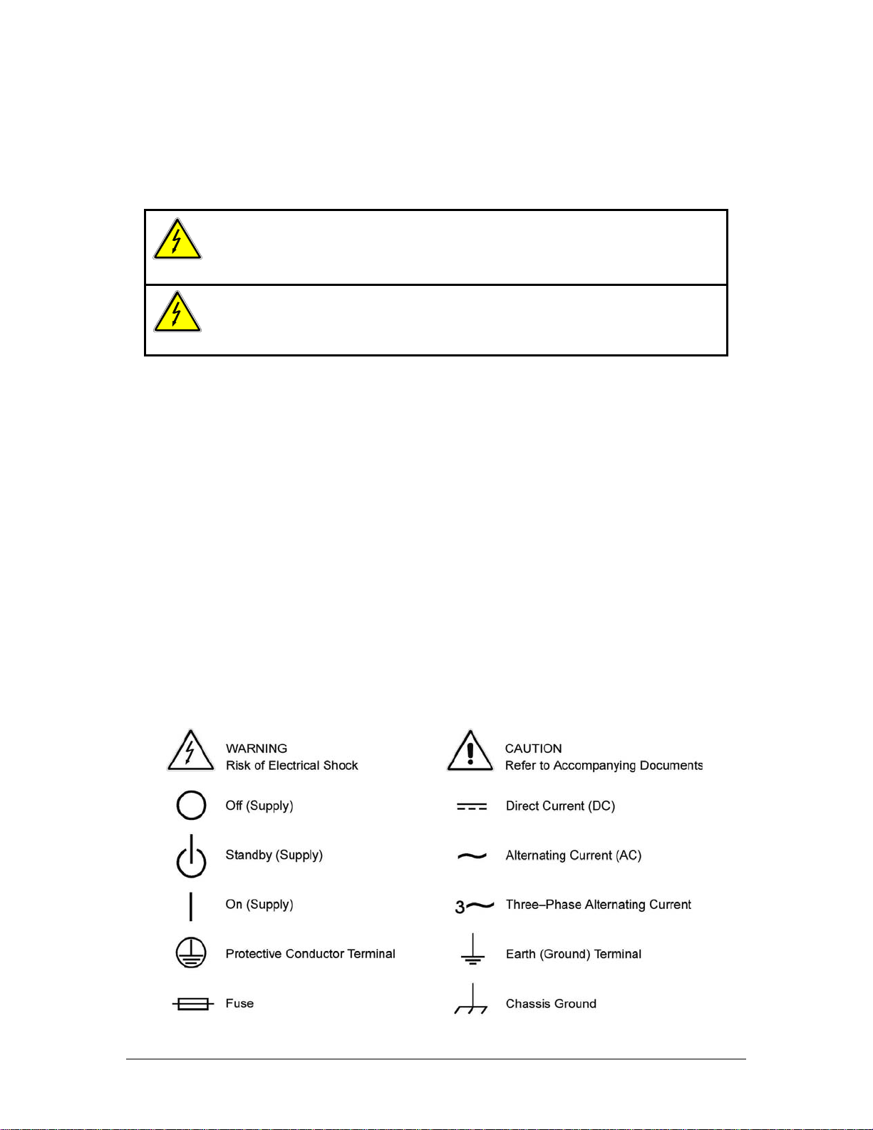
through Figure 1-4 show the power contours for each model of the SLD-series Electronic Load:
60
30
Voltage (V)
10
0
8.34.2
02550
Curr e n t (A mps)
a) b) c)
Figure 1-1 Power contour for: a) Channel A of SLD-60-505-255 and SLD-61-505-255;
b) Channel B of SLD-60-505-255; c) Channel B of SLD-61-505-255 electronic loads
60
30
20
Voltage (V)
10
0.5
0
02.5 5
1.7
0.83
Current (Amps)
60
30
20
- Volt a ge (-V)
10
1
0
02.55
1.70.83
Current (Amps)
M540075-01 Rev C 1-1
Page 14
Introduction Sorensen SLD-Series DC Load
80
60
30
40
Volta ge (V)
10
5
1
0
01020
8.34.2
Current (Amps)
Voltage
10
5
0.4
0
0 10
2.51.25
Current (Amps)
20
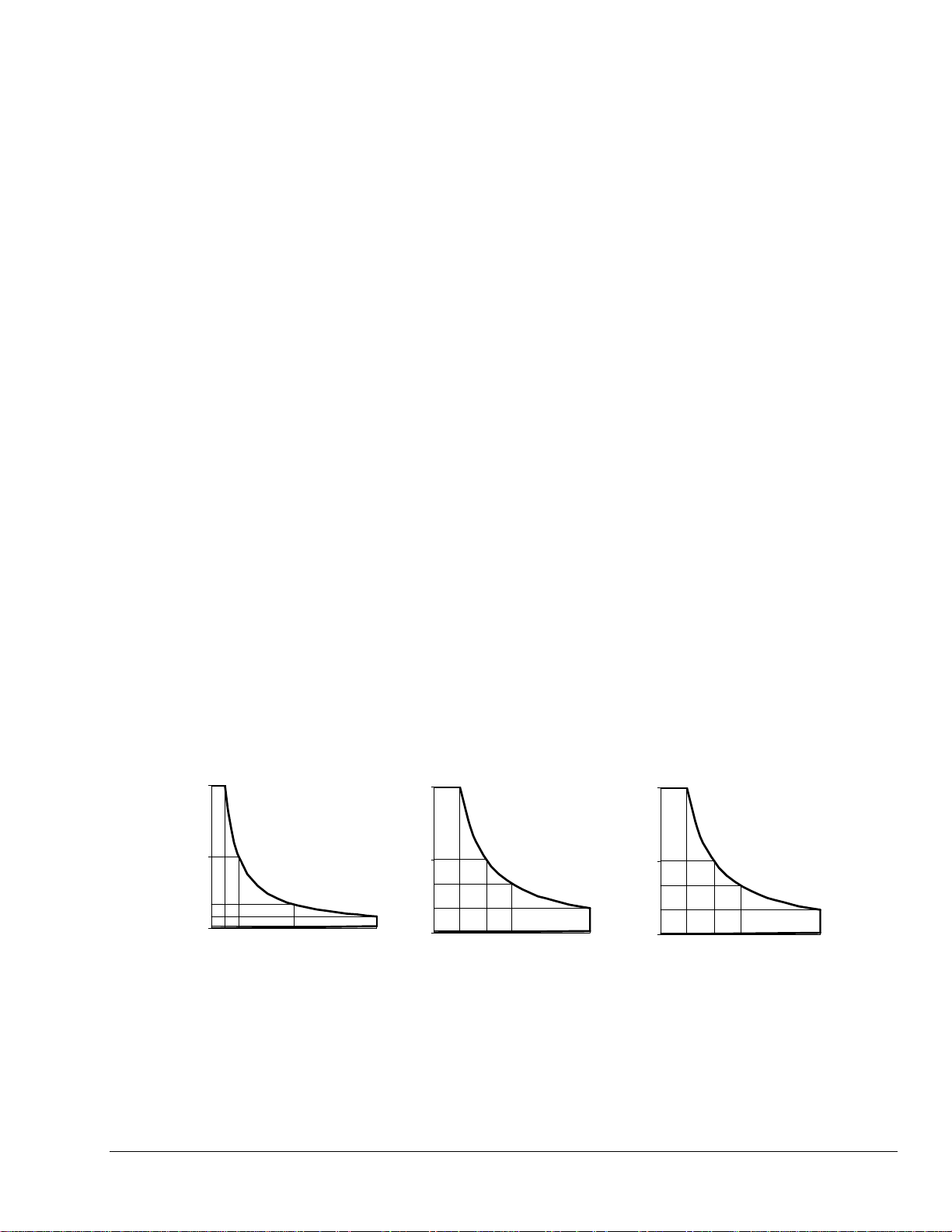
Figure 1-2 Power Contours for SLD-60-20-102 and SLD 80-20-102 Electronic Load Channels A and B
60
30
Voltage (V)
15
0.5
0
1.25
02.55
SLD-61-5-752 Channel A SLD-61-5-752 Channel B, SLD-62-5-752 Channel A and B
Cu rrent (Amps)
60
30
- Voltage (-V)
15
1
0
1.25
02.55
Current (Amps)
Figure 1-3 Power Contours for SLD-61-5-752 and SLD-62-5-752 Electronic Load Modules
60
30
Voltage (V)
10
5
1
0
4.2
8.3
050100
Current (Amps)
Channel A Channel B
60
30
Voltage (V)
20
10
0.5
0
02.55
1.70.83
Current (Amp s)
Figure 1-4 Power Contours for SLD-60-105-550 Electronic Load
1-2 M540075-01 Rev C
Page 15
Sorensen SLD-Series DC Load Introduction
CC
1.1.1 Operating Modes
The operating modes of the SLD-series Electronic Load include Constant Current (CC) mode,
Constant Resistance (CR) mode, and Constant Voltage (CV) mode. The wide range dynamic
load with rise/fall current slew rate is available in CC mode only.
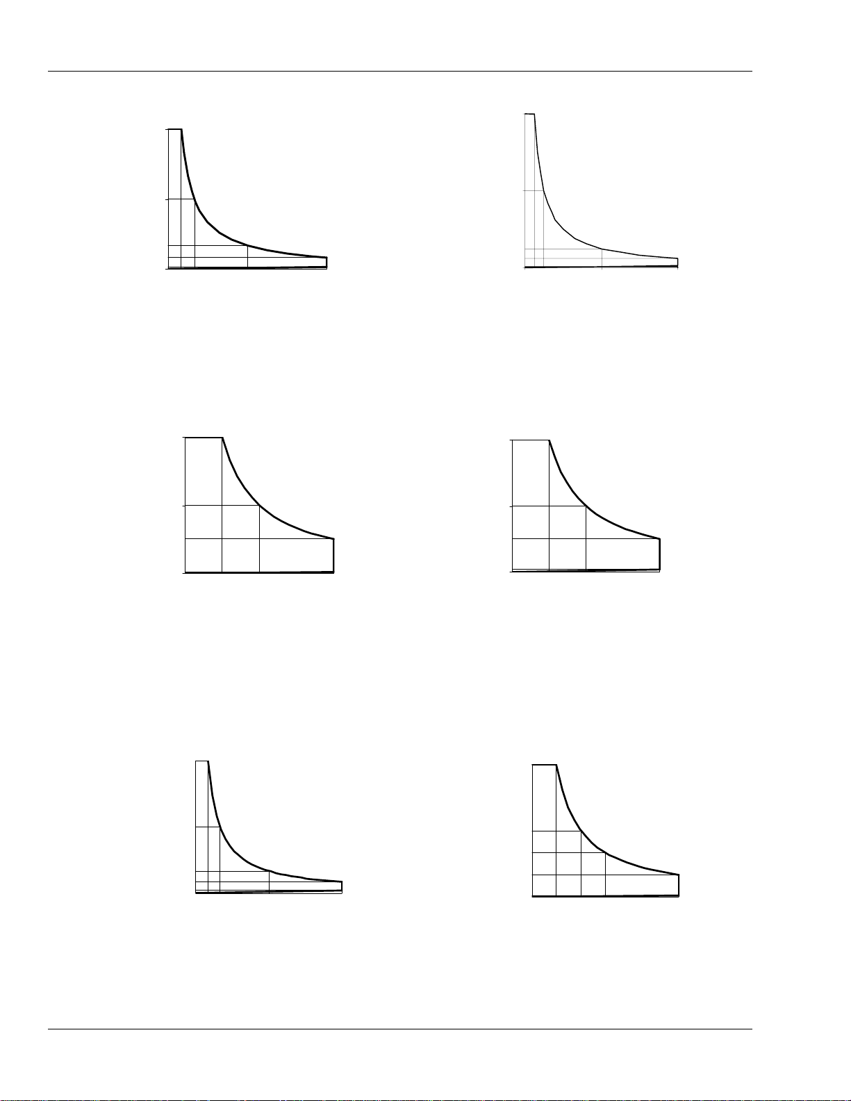
CC Mode: (Constant Current mode)
With the operating mode of constant current, the SLD-series Electronic load will sink a
current in accordance with the programmed value regardless of the input voltage (see
Figure 1-5).
I
LOAD
CURRENT
CURRENT SETTING
V
INPUT VOLTAGE
Figure 1-5 Constant Current Mode
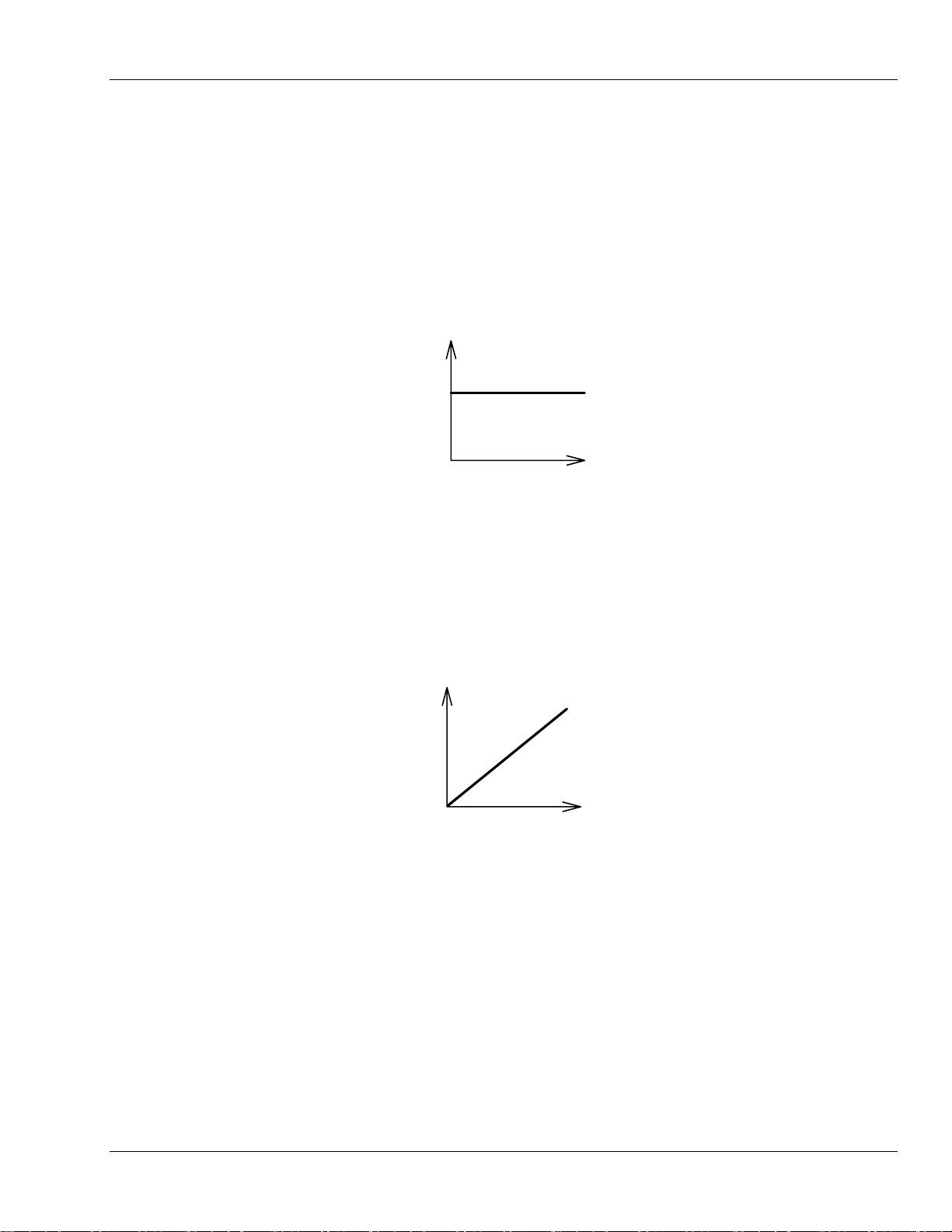
CR Mode: (Constant Resistance Mode)
At constant resistance mode; the SLD-series Electronic Load will sink a current linearly
proportional to the load input voltage in accordance with the programmed resistance
setting (see Figure 1-6).
I
LOAD
CURRENT
RESISTANCE
SETTING
V
INPUT VOLTAGE
Figure 1-6 Constant Resistance Mode
M540075-01 Rev C 1-3
Page 16
Introduction Sorensen SLD-Series DC Load
CV Mode: (Constant Voltage Mode)
At constant voltage mode; the SLD-series Electronic Load will attempt to sink enough
current until the load input voltage is equaled to the programmed value (see Figure 1-7).
I
VOLTAGE
LOAD
CURRENT
SETTING
V
INPUT VOLTAGE
Figure 1-7 Constant Voltage Mode
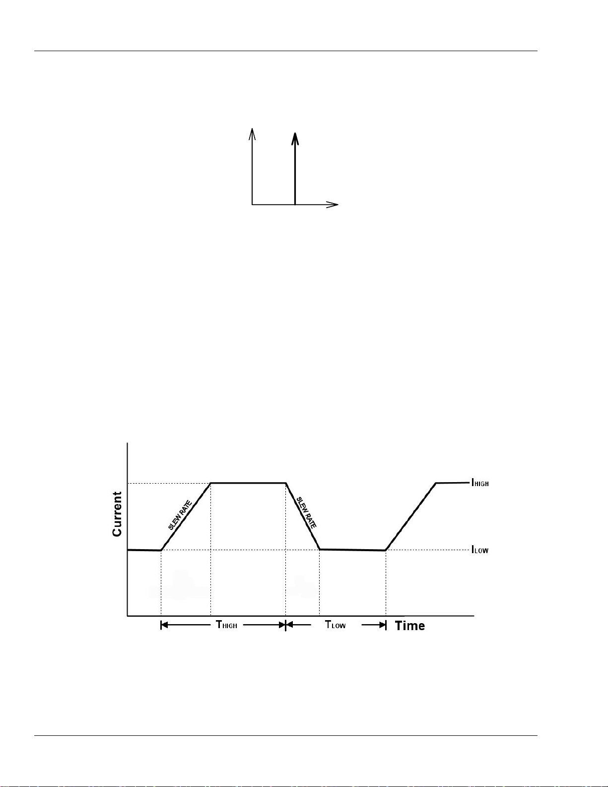
Dynamic Waveform Definition:
There are six parameters to generate dynamic waveform or pulse waveform: High Load
Level, Low Load Level, T
HIGH, TLOW, and Rise and Fall Slew Rates. The SLD-series
Electronic Load will sink current from the power source proportional to the dynamic
waveform, the definition for which is shown in Figure 1-8. The period of dynamic
waveform is T-high + T-low.
Dynamic frequency = 1 /( T-high + T-low )
Duty cycle = T-high / ( T-high + T-low )
Figure 1-8 Dynamic Waveform
1-4 M540075-01 Rev C
Page 17
Sorensen SLD-Series DC Load Introduction
1.2 Features of the SLD-Series Dual DC Electronic Load
The SLD-series dual DC Electronic load includes six models, where 200-300W models are
suitable for PS/2,ATX personal computer power supply testing, 150W models are for low
power output power supply (ex. DC/DC converter) testing applications, the 550W module is
designed for higher power computer server power supply applications.
• Very flexible Dual Load configuration to SLM mainframe with maximum power up to
300W (250W+50W) for single-bay module or up to 550W for the dual bay module; it
meets multiple output power supply test requirements.
• Both Front panel and Remote control are available; the remote interface can be built-in
RS-232 or GPIB with setting and read-back capability. (GPIB is optional in the SLM-1
chassis).
• Dual Voltage and current meter display with 16-bit high accuracy/resolution A/D
converter.
• Built-in Dynamic pulse generator for dynamic loading control.
• Meter reading GO/NG check capability.
• Short circuit load testing capability with short circuit current measurement.
• Built-in 150 sets Store/Recall EEPROM memory.
• Protection against Over Voltage, Over current, Over power, Over temperature, and
reverse polarity.
• Built-in power supply OCP and OVP testing function.
• Power supply output automatic testing by the auto-sequence function of mainframe.
• Programmable Load ON and Load OFF voltage control.
• Advance Cooling Fan control, the fan speed is proportional to the load power, the fan
noise can be reduced in low power applications.
1.2.1 Accessories for Each Module
Accessories SLD-60-505-255 SLD-61-505-255
Miniature banana plug (Red) 2 1 2 1 0 2
Miniature banana plug (Black) 2 2 2 2 2 2
Miniature banana plug (White) 0 1 0 1 2 0
Banana plug (Red) 2 1 2 1 0 4
Banana plug (Black) 2 2 2 2 2 4
Banana plug (White) 0 1 0 1 2 0
Heavy spread lug terminal 2 2 0 0 0 4
Spread lug terminal 2 2 4 4 4 2
Operation manual 1 1 1 1 1 1
SLD-60-20-102/
SLD-80-20-102
SLD-61-5-752 SLD-62-5-752 SLD-60-105-550
Table 1-1 Accessories Included with Each SLD-series Module
M540075-01 Rev C 1-5
Page 18
Introduction Sorensen SLD-Series DC Load
μ
μ
μ
μ
1.2.2 Specifications
The following specifications apply 25°C ± 5°C
MODEL SLD-60-505-255 SLD-61-505-255 SLD-60-20-102 SLD-80-20-102 SLD-61-5-752 SLD-62-5-752 SLD-60-105-550
INPUT RATING
Voltage CH. A: +60V CH. B: +60V CH. A: +60V CH. B: -60V +60V x 2 +80V x 2
Current 50A 5A 50A 5A 20A x 2 20A x 2 5A X 2 5A X 2 100A 5A
Min. Voltage (Full Current): 0.4V 0.4V 0.4V 0.9V 0.4V 0.4V 0.4V 0.3V 0.4V 0.4V
CC MODE
CR MODE
Range 1 (I>0.02% of rating) 1.2-4500Ω 12 - 45000Ω 1.2-4500Ω 12 - 45000Ω 3 - 11250Ω 4 - 15000Ω
Range 2 (I>0.2% of rating) 0.04-1.2Ω 0.4 - 12Ω 0.04-1.2Ω 0.4 - 12Ω 0.1 - 3Ω 0.134 - 4Ω 0.4 - 12Ω 0 .02 - 0.6Ω 0.4 - 12Ω
CV MODE
SHORT MODE
DYNAMIC MODE
4 1/2 DVM
4 1/2 DAM
Load ON Volt.
Load OFF Volt.
Weight
Power 250W 50W 250W 50W 100W x 2 100W x 2 75W x 2 75W x 2 500W 50W
Range 0 - 5A / 50A 0-0.5A / 5A 0 - 5A / 50A 0-0.5A / 5A
Resolution 1.34 / 13.4mA 0.134 / 1.34mA 1.34 / 13.4mA 0.134 / 1.34mA
Accuracy
Range
Resolution
Accuracy
Resistance 8mΩ 0.08Ω 8mΩ 0.18Ω 0.02Ω 0.02Ω 0.2Ω 0.06Ω 4mΩ 0.08Ω
Current 50A 5A 50A 5A 20A 20A 5A 5A 100A 5A
THIGH / TLOW
4 - 200 mA/μs
Slew Rate
40-2000 mA/μs
Resolution
Accuracy
Resolution
Accuracy
Resolution 1mA / 10mA 0.1mA / 1mA 1mA / 10mA 0 .1mA / 1mA
Accuracy
Resolution
Accuracy
Resolution
Accuracy
0.8 mA/μs
8 mA/
Range
Range 15A / 50A 1.5A / 5A 15A / 50A 1.5A / 5A
Range
Range
0.4 - 20 mA/μs
4 - 200 mA/μs
s
0.08 mA/μs
0.8 mA/μs
0.2% of (Setting + Range) 0.2% of (Setting + Range)
0 – 60V 0 - 60V 0 - 80V 0 – 60V
16mV 16mV 21.3mV 16mV
0.2% of (Setting + Range) 0.2% of (Setting + Range)
50μsec to 9.999 sec 50μsec to 9.999 sec
4 - 200 mA/μs
40-2000 mA/μs
0.8 mA/μs
8 mA/μs
15V / 60.00V 20V / 80V 15V / 60.00V
0.4 - 20 mA/μs
4 - 200 mA/μs
0.08 mA/μs
0.8 mA/μs
±10% OF (Setting + 10
0.2% of (Reading + Range) 0.2% of (Reading + Range)
s) ±10% OF (Setting + 10μs)
3.5 kgs. / 7.7 lbs. 7 kgs. / 15.4 lbs.
0 - 2.0A / 20A
0.534 / 5.34mA
1.6-80 mA/μs
16-800 mA/μs
0.32 mA/
s
3.2 mA/μs
0.001V / 0.01V
0.05% of (Reading + Range)
2.0A/20A
0.1mA / 1mA
0.1-25V
0.1V
1% of Setting + 0.25V
0-25V
1mV
1% of Setting + 0.25V
CH.A: +60V,
CH. B: -60V
0 - 0.5A / 5A 0 - 0.5A / 5A 0 - 1.0A / 100A 0 - 0.5A / 5A
0.134 / 1.34mA 0.134 / 1.34mA 2.66/26.6mA 0.134 / 1.34mA
1.5A / 5A 10/100A 1.5A / 5A
0.1mA / 1mA 1/10mA 0.1mA / 1mA
CH. A: -60V, CH.
12 - 45000Ω
0.4 - 20 mA/μs
4 - 200 mA/μs
0.08 mA/μs
0.8 mA/μs
B: -60V
CH. A: +60V CH. B: +60V
0.6 - 2250Ω 12 - 45000Ω
8-400 mA/μs
80-4000 mA/μs
1.6 mA/μs
16 mA/
0.4 - 20 mA/μs
4 - 200 mA/μs
s
0.08 mA/μs
0.8 mA/μs
Table 1-2 SLD-series Specifications
1-6 M540075-01 Rev C
Page 19
Sorensen SLD-Series DC Load Introduction
1.2.3 Environmental Requirements
• For indoor use only
• Installation Category II (over voltage)
• Pollution Degree 2
• Altitude up to 2000 meters (with power derating)
• Relative Humidity 80% RH Max
• Ambient Operating Temperature 0-40°C, with ideal being 25°C ± 5°C
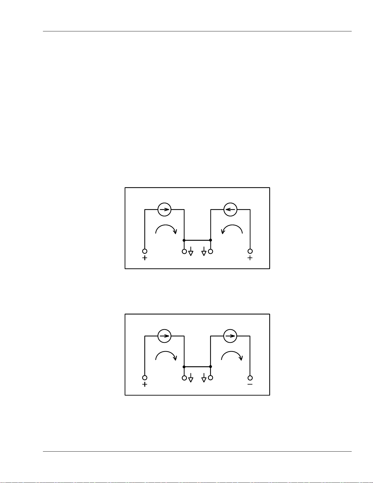
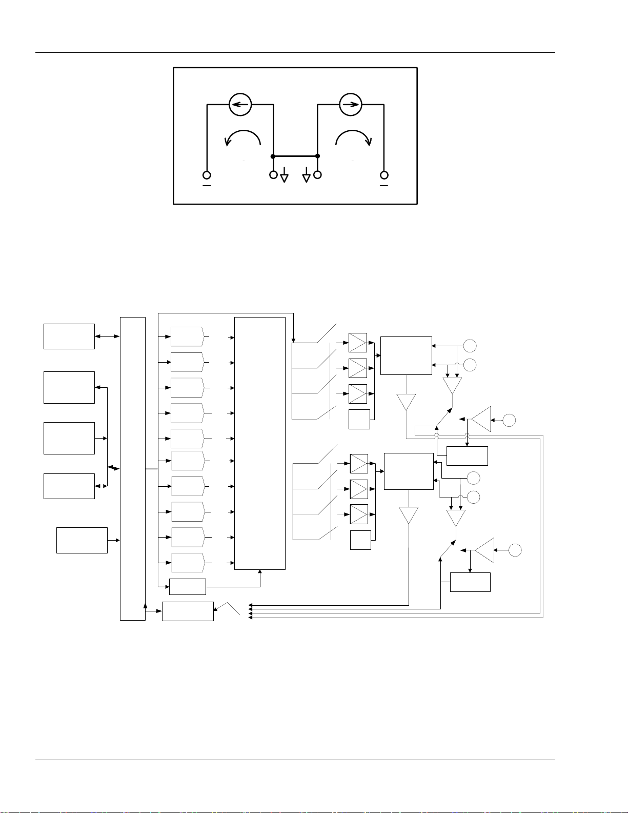
1.2.4 System Equivalent Circuit and Block Diagram
The equivalent polarity circuit diagrams of SLD-series Dual DC Electronic Load are shown
below:
CHAN.A CHAN.B
IA IB
COM COM
Figure 1-9 SLD-60-xxx-xxx: Dual Positive Load Channel
CHAN.A CHAN.B
IA IB
COM COM
Figure 1-10 SLD-61-xxx-xxx: Channel A/B is Positive/Negative Load Channel, Respectively
M540075-01 Rev C 1-7
Page 20
Introduction Sorensen SLD-Series DC Load
CHAN.A CHAN.B
IA IB
COM COM
Figure 1-11 SLD-62-xxx-xxx: Dual Negative Load Channel
The system functional block diagram of SLD-series Electronic Load module is illustrated in
Figure 1-12. The functional block diagram of the mainframe is described in the SLM
mainframe operation manuals.
CHANNEL A
Memory
Front Panel
Display and
Keyboard
OTP Protection
Circuitry
Serial Port
Osciallator Circuit
CPU
12-bit
12-bit
16-bit
Timer
16-bit
Timer
12-bit
12-bit
16-bit
Timer
16-bit
Timer
Load ON
Control
16-bit A/D
DVM/DAM
D/A
D/A
8-bit
D/A
D/A
D/A
D/A
D/A
8-bit
D/A
D/A
D/A
LOW
LEVEL
HIGH
LEVEL
SLEW
RATE
T
HIGH
T
LOW
LOW
LEVEL
HIGH
LEVEL
SLEW
RATE
T
HIGH
T
LOW
Dynamic Function
Control
MODE Select
CHANNEL B
MODE Select
DVM/DAM
Select
CC
CR
CV
Range
I/II
CC
CR
CV
Range
I/II
Power MOSFET
Stage
Power MOSFET
Stage
Current
Sense
Current
Sense
Vsense
Control Circuit
Vsense
Control Circuit
LOAD
INPUT
LOAD
INPUT
Vsense
Input
Vsense
Input
Figure 1-12 SLD-series Block Diagram
Each load channel receives the load levels and load status from the chassis via either serial
optical isolated bus or keyboard.
• two 12-bit D/A converters receive digital data of the high and low load levels and
transfer them as an analog signal to the Dynamic Function Generator (DFG)
• two 8-bit D/A converters control the load current slew rate and feed into the DFG
1-8 M540075-01 Rev C
Page 21

Sorensen SLD-Series DC Load Introduction
• two 16-bit timers set current THIGH and TLOW duration and feed into the DFT
• the DFG sends analog signals to the Load Control Circuit
• one of Constant Current (CC), Constant Resistance (CR), or Constant Voltage (CV)
and one range level is selected, depending on which mode and range are operating
• the drive circuit controls the load current flow through power MOSFET
• the current sense Amplifier, built into the power MOSFET stage, feeds the load
current signal to 16-bit DAM.
• the voltage V-sensing circuit selects the Load input terminal or V-sense BNC input,
depending on the CONFIG key's V-sense ON/OFF setting, and feeds the voltage
signals to 16-bit DVM
The 16-bit voltage and current meter digital bus feeds back to the CPU circuitry; each SLDseries load module can transfer to chassis through isolated serial circuitry.
M540075-01 Rev C 1-9
Page 22

Introduction Sorensen SLD-Series DC Load
This page intentionally left blank.
1-10 M540075-01 Rev C
Page 23
SECTION 2
INSTALLATION
This Section discusses the installation and removal of SLD-series Electronic load modules from the
SLM mainframe. The SLD-series load module plugs into any channel of the SLM mainframe and does
not need any adjustment after plug in.
WARNING: Only qualified personnel should do installation and removal.
Figure 2-1 Load Input Connector and Screw for Single-Bay Unit
M540075-01 Rev C 2-1
Page 24
Installation Sorensen SLD-Series DC Load
Figure 2-2 550W Load Input Connector and Screw for Double-Bay Unit
2-2 M540075-01 Rev C
Page 25
Sorensen SLD-Series DC Load Installation
2.1 Installation and Removal of SLD-Series Module
Unless the SLM mainframe and SLD-series Electronic load module were purchased separately,
the SLD-series Electronic load module should be installed in the mainframe before shipment
from Sorensen.
The SLD-series Electronic load module operates in SLM mainframe for front panel and remote
control feature, but cannot be operated without the mainframe.
When you want to install or remove the SLD-series load module into or from the SLM
mainframe for configuration or reconfiguration purposes, please follow the procedures in
Section 2.1.1 or 2.1.2.
CAUTION: PREVENT DAMAGE TO THE LOAD. Do NOT apply voltage or current
with chassis power switched OFF. Turn ON the power switch to the load PRIOR to
applying voltage or current to the input terminals (i.e., before turning on the power
supply under test).
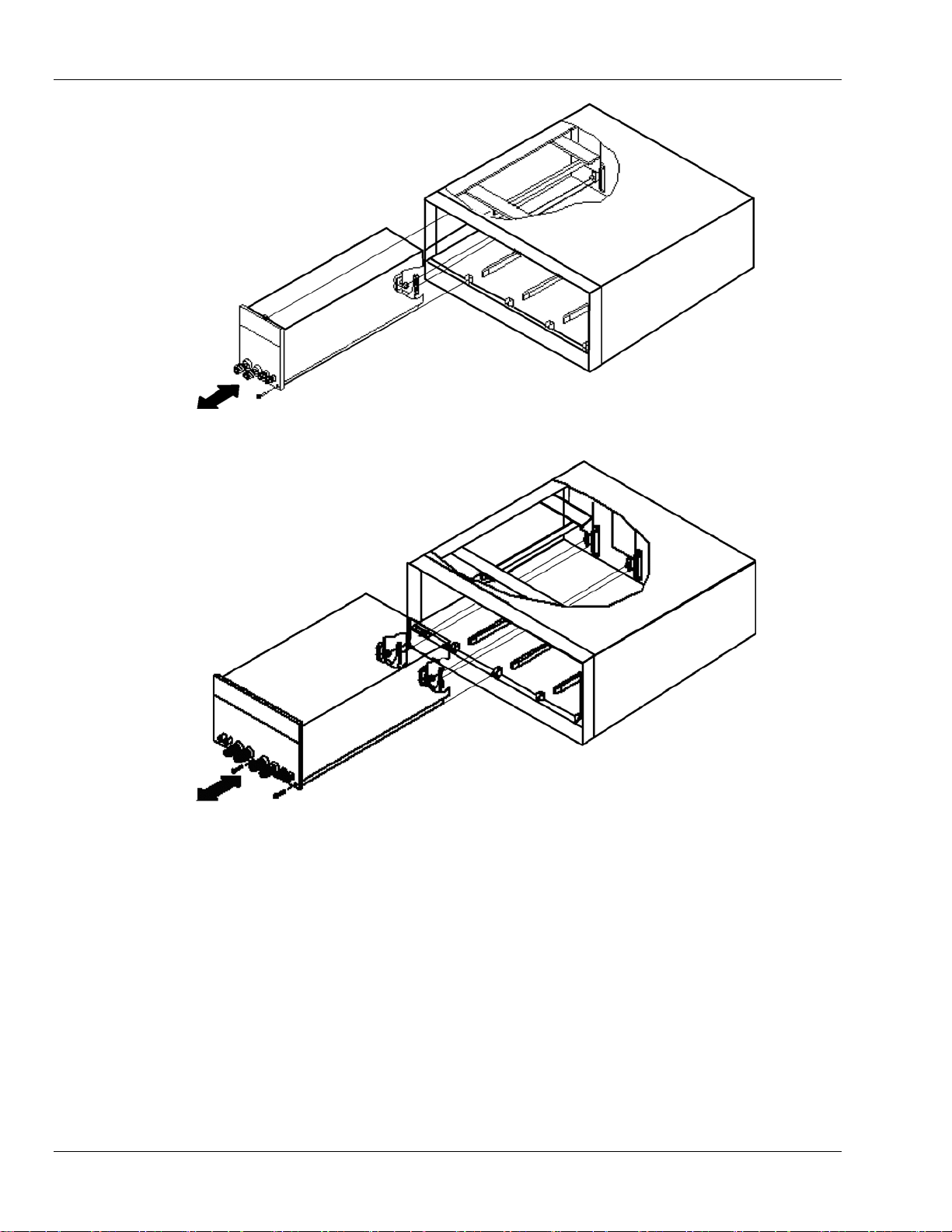
2.1.1 Installation
1. Turn the chassis power OFF before inserting the SLD-series load module, or damage
may occur to the plug-in module circuitry.
2. Align the upper and lower grooves of the mainframe with the upper and lower guides of
the selected compartment.
3. Push the SLD-series load module in and press firmly on the binding posts of the front
panel to seat the circuit board in the interconnecting jack.
4. Fasten the screw on the lower and right hand side corner of the SLD-series front panel
with screwdriver, the screw location is shown on Figure 2-2.
5. Turn the chassis power ON until all of the electronic modules are completely installed.
2.1.2 Removal
1. Turn the chassis power OFF first; otherwise, damage may occur to the plug-in circuitry.
2. Loosen the screw on the front panel of SLD-series with screwdriver.
3. Turn the adjustment knob of the black binding post counter clockwise until the
adjustment knob is fully moved out; Then pull on the black adjustment knob of binding
post until the interconnecting jack disengages and SLD-series load module will slide out.
M540075-01 Rev C 2-3
Page 26
Installation Sorensen SLD-Series DC Load
Figure 2-3 Single Bay, Dual Input Electronic Load Module Plug-in and Removal
Figure 2-4 Dual Bay Electronic Load Plug-in and Removal
2.2 Input Binding Post and Wire Considerations
There are five ways that binding posts (+, com and -) can connect the input wires to the
Electronic:
2.2.1 Plug Connectors
This is the most popular way to connect the input of electronic load to the device under test.
It is recommended the load current be less than 20A in this connection since the current
rating of the plug is rated to 20A. The maximum wire gauge should be limited to AWG14.
2-4 M540075-01 Rev C
Page 27

Sorensen SLD-Series DC Load Installation
2.2.2 Hook Terminals
The hook terminal provides a good contact to the binding post and can be used anytime.
The maximum wire gauge should be limited to AWG10.
2.2.3 Direct Insertion into Binding Posts
This is the most convenient way to connect the load input to the DUT. The maximum wire
gauge AWG14 can be used in this application.
2.2.4 Plug Connectors and Hook Terminals
This method is recommended when input current is greater than 20A or long lead wires.
2.2.5 Plug Connectors and Direct Insertion
This method is also recommended when input current is greater than 20A or long lead wires.
A major consideration in making input connection is the wire size. The minimum wire size is
required to prevent overheating and to maintain good regulation.
Note:
SLD-series dual Electronic Load's Channel A and Channel B Load input connector has
common connections, this means the ground common point (Black binding post) for
Channel A and B is wired together.
• 2 positive (+) load modules should be used for two positive output power supply test
applications
• one positive (+) one negative (-) load module should be used for one positive (+) one
negative (-) output power supply test application
• 2 negative (-) load modules should be used for two negative output power supply test
applications,
However, each Dual DC Electronic Load module common input is isolated to the other
Load module, therefore, please make a polarity combination consideration for power
supply and the Dual Load module. See Figure 1-9 to Figure 1-11.
M540075-01 Rev C 2-5
Page 28

Installation Sorensen SLD-Series DC Load
This page intentionally left blank.
2-6 M540075-01 Rev C
Page 29

SECTION 3
OPERATION
This chapter describes the front panel operation of each SLD-series Dual DC load module. The GPIB
and RS-232 remote programming are described in the SLM mainframe operation manual.
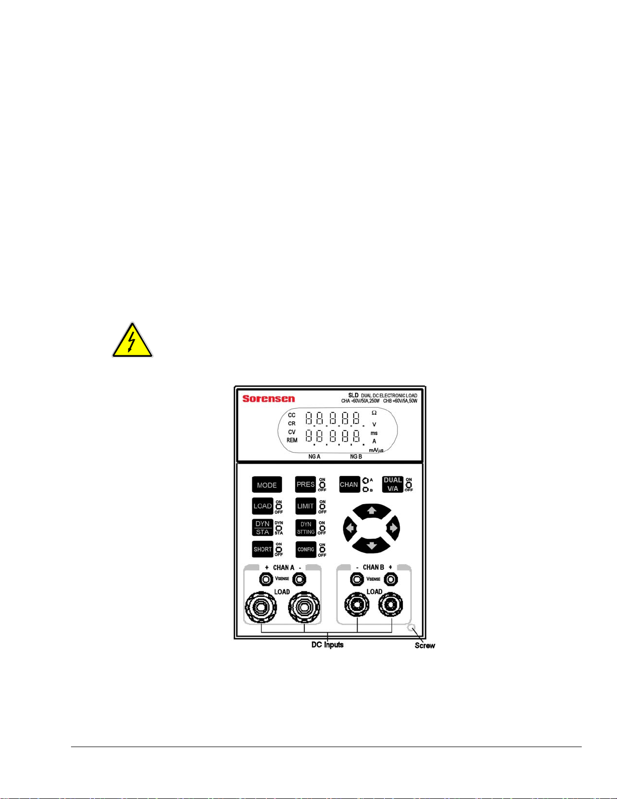
3.1 Front Panel Controls and Indicators
Figure 3-1 SLD-series Dual DC Electronic Load Front Panel, Single Bay
M540075-01 Rev C 3-1
Page 30

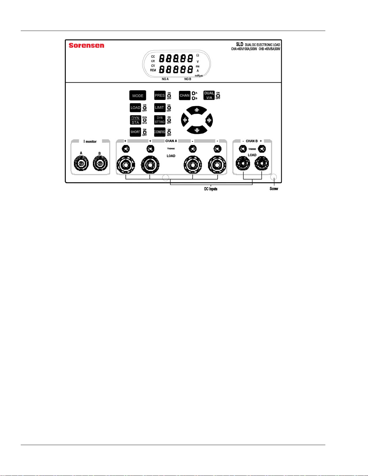
Operation Sorensen SLD-Series DC Load
Figure 3-2 SLD-series Dual DC Electronic 550W Load Front Panel, Double Bay
3.1.1 Descriptions
1 Module Label
Shows the load model name and its maximum ratings.
2 CHAN Key and A/B LEDs
Selects either channel A or B for front panel control (REM LED and DUAL V/A key do not
apply).
• CHAN key toggles control selection between Channel A and Channel B.
• LEDs indicate which channel is selected:
◦ A = front panel is controlling Channel A
◦ B = front panel is controlling Channel B
3 MODE Key and CC, CR, CV LEDs
Selects among Constant Current, Constant Resistance, or Constant Voltage modes.
• MODE key toggles from one mode to the next.
• LEDs indicate which mode is operating:
◦ CC = Constant Current
◦ CR = Constant Resistance
◦ CV = Constant Voltage
3-2 M540075-01 Rev C
Page 31

Sorensen SLD-Series DC Load Operation
4 REM LED
Indicates remote operation:
• When lit, the unit is under remote control and cannot be operated through the front
panel keys.
• When off, the unit is under local control and can be manually operated using the
front panel keys.
5 NG A LED
When enabled and Channel A is selected (CHAN A LED is lit), indicates whether or not
Voltage and/or Current exceed(s) the upper or lower limit set for channel A.
• Lit = “No Go” – Channel A Voltage and/or Current limits exceeded.
• Not lit = "Go" (no fail) for Channel A.
NOTE: Use the CONFIG key, 14, to set NG ON/OFF to ON, to enable this function.
6 NG B LED
When enabled and channel B is selected (CHAN B LED is lit), indicates whether or not
Voltage and/or Current exceed(s) the upper or lower limit set for channel B.
• Lit = “No Go” – Channel B Voltage and/or Current limits exceeded.
• Not lit = "Go" (no fail) for Channel B.
NOTE: Use the CONFIG key, 14, to set NG ON/OFF to ON, to enable this function.
7 Upper 5-Character Display and Associated LEDs
Multi-purpose display, depending on selected mode:
• In PRESet OFF mode, displays voltage of DC input terminal or VSENSE BNC input.
• In PRESet ON mode, displays values being programmed for CR or CV.
• In DYN STTING On mode, displays dynamic waveform parameters for:
◦ High Level Current (Curr-H)
◦ Low Level Current (Curr-L)
◦ High Load Duration (T-Hi)
◦ Low Load Duration (T-Lo)
◦ Slew Rate (Sr)
• In LIMIT ON mode:
◦ displays GO/NG limit values for voltage
◦ displays “AH” or “AL” when current limits a being programmed (see DYN
STTING key, 12)
• In CONFIG ON mode:
◦ displays SENSE to indicate V
SENSE control
◦ displays voltage settings for LOAD ON or for LOAD OFF
M540075-01 Rev C 3-3
Page 32

Operation Sorensen SLD-Series DC Load
• Protection notice:
◦ Displays “Prot” when over- protection is triggered (lower display reveals which
protection feature was triggered).
Associated LEDs indicate the displayed value's unit:
• Ω = Value displayed is in Ohms
• V = Value displayed is in Volts
• ms = Value displayed is in milliseconds
• A = Value displayed is in Amps
• mA/μs = Value displayed is in Amps per microsecond (or milliamps per
microsecond)
8 Lower 5-Character Display and Associated LEDs
Multi-purpose display, depending on selected mode:
• In PRESet (key 9) OFF mode:
◦ displays actual load current when SHORT status is OFF
◦ displays short circuit current when SHORT status is ON
• In PRESet ON mode, displays:
◦ value being programmed for CC
◦ values being programmed for T
HIGH/TLOW when in Dynamic mode
◦ values being programmed for Curr-H/Curr-L when in Dynamic mode
◦ values being programmed for RISE/FALL slew rates when in Dynamic mode
• In LIMIT (key 15) ON mode:
◦ displays oVP (over voltage), oCP (over current), oPP (over power), or
oTP (over temperature) when in protection mode
◦ displays GO/NG low limit values for voltage, current, and power
◦ displays Auto or On setting for V
SENSE control
◦ displays either Ld-on or Ld-off to indicate whether Load voltage setting mode is
On or Off
Associated LEDs indicate the displayed value's unit:
• Ω = Value displayed is in Ohms
• V = Value displayed is in Volts
• ms = Value displayed is in milliseconds
• A = Value displayed is in Amps
• mA/μs = Value displayed is in Amps per microsecond (or milliamps per
microsecond)
9 PRES Key and ON/OFF LED
• PRES key This key toggles between Preset ON and Preset OFF
3-4 M540075-01 Rev C
Page 33

Sorensen SLD-Series DC Load Operation
• LED indicates the status of the Preset function:
◦ Lit = Preset function is on.
◦ Not lit = Preset function is off.
10 LOAD Key and ON/OFF LED
• LOAD key toggles ON/OFF the DC load input function. (Does not affect the
programmed settings).
• LED indicates the status of the Load function:
◦ lit = Load function is ON and ready to sink current from the DC input.
◦ not lit = Load circuit is open function is OFF.
11 DYN / STA Key and LED
• DYN/STA key toggles between Dynamic and Static modes only when in Constant
Current mode.
• When the SLD-series Load module is in Constant Resistance mode or Constant
Voltage mode, this key is not functional, and the module defaults to Static Mode.
• LED indicates whether the load module is in Dynamic or Static mode:
◦ lit = Dynamic mode is active.
◦ not lit = Static mode is active.
12 DYN STTING Key and ON/OFF LED
This key scrolls through the five waveform parameters so that you can set the Dynamic
load level for each: Current High, Current Low, Time High, Time Low, and Slew Rate,
displayed as Curr-H, Curr-L, T-Hi, T-Lo, and Sr, respectively.
• LED indicates the status of the Dynamic Setting function:
◦ lit = Dynamic Setting function is ON.
◦ not lit = Dynamic Setting function is OFF.
NOTE: Setting the duration (T-Hi and T-Lo) for one channel (either A or B),
simultaneously sets the other channel to the same duration.
13 Navigation Keys
• The left/right arrows select the digit to be modified.
• The increment/decrement arrows increase/decrease the value of the selected
(blinking) digit.
14 CONFIG Key and ON/OFF LED
• This key scrolls through the parameters to be configured for either setting values or
for enabling/disabling (ON/OFF) functions: Vsense On/Off, NG check On/Off,
Load-on voltage, Load-off voltage, Istart, Istop, Istep, voltage threshold, test (OCP
or Normal), and parallel On/Off (Parallel not available for SLD-61 Models due to
+/- polarity difference).
• Use the Navigation keys, 13, with the Configuration function to make the desired
M540075-01 Rev C 3-5
Page 34

Operation Sorensen SLD-Series DC Load
ON/OFF selections or value changes.
• The LED indicates the status of the Configuration function:
◦ lit = Configuration function is ON.
◦ not lit = Configuration function is OFF
15 LIMIT Key and ON/OFF LED
Scrolls among the parameters whose limits you can set.
• The Limit key sequentially selects the following parameters to program their
settings:
◦ upper Voltage limit
◦ lower Voltage limit
◦ upper Current limit
◦ lower Current limit
◦ returns to OFF and the loop repeats
• the Navigation keys, 13, are used with the Limit function to set the desired values.
• The LED indicates whether limits are being programmed or not:
◦ lit = Limit function isON.
◦ not lit = Limit function is OFF.
16 SHORT Key and ON/OFF LED
• The SHORT key toggles the short circuit of the input terminal On and Off.
• LED indicates the ON/OFF status of the short circuit
◦ lit = ON
◦ not lit = OFF
17 DUAL V/A Key and ON/OFF LED
This key is used to display the dual voltage or current.
• DUAL V/A scrolls in the following sequence:
◦ Voltage for Channel A in upper display (7) and for Channel B in lower display (8)
◦ Current for Channel A in upper display and for Channel B in lower display
◦ returns to OFF and the loop repeats
• The LED indicates whether or not the digital meter is displaying dual voltage or
current for channels A and B.
◦ lit = dual voltage or current is being displayed in the digital meter display
◦ not lit = OFF
• Associated LEDs:
◦ V = Value displayed is in Volts
◦ A = Value displayed is in Amps
3-6 M540075-01 Rev C
Page 35

Sorensen SLD-Series DC Load Operation
18 -/+ DC INPUT Binding Posts
The negative (left) and positive (right) terminal of load input connector
• Connect the red, positive (+) Load input connector to the power source’s positive
output.
• Connect the white, negative (-) load input connector to the power source’s negative
output.
• Connect the black, ground (com) output for a negative output power supply.
NOTE: Before testing, ensure that the voltage and current do not to exceed the
maximum rating of each SLM-series DC load module and the connection method
utilized.
Also check the polarity of DC input connection before testing.
19 V
SENSE
Used to measure the specific voltage points through the V-sense BNC cable.
• Connect the red, positive (+) V-sense connector to the power source’s positive
output.
• Connect the white, negative (-) V-sense connector to the power source’s negative
output.
• Connect the black, ground (com) V-sense connector to the power source’s
common output.
NOTE: Use the CONFIG key to set the V
SENSE function to ON.
I monitor (double bay unit only; see Figure 2-2)
Provides the load current waveform output to an oscilloscope to evaluate the current
waveform of a power supply under test.
M540075-01 Rev C 3-7
Page 36

Operation Sorensen SLD-Series DC Load
3.1.2 Summary Chart
The front panel controls are summarized in Figure 3-3.
SLD Dual DC Loads
Button Functions
MODE
CC: Constant Current
CR: Constant Resistance
CV: Co nstant Volta ge
PRESet
ON
OFF
LIMIT
G/NG Volt Up per Limit
G/NG Volt Lower Limit
G/NG Current Upper Limit
G/NG Current Lower Limit
CONFIG
Vsense
OFF
ON
G/NG
OFF
ON
Load On Voltage
Load Off Voltage
iStart Current
iStop Current
iStep Current
Vthreshold
Test Mode
Normal
OCP
Parallel Setup A IIb
OFF
ON
DYN/STA
DYNamic
STAtic
Figure 3-3 Organization of Front Panel Controls of SLD Electronic Load
3.2 Operation – Setup and OCP Test
The SLD-series dual input DC loads can operate in five modes: Constant Current (CC),
Constant Voltage (CV), Constant Resistance (CR), Shorts, and Dynamic. Dynamic mode allows
controlled current transitions between two states in CC.
SHORT
ON
OFF
LOAD
ON
OFF
DYN STTING
High Le vel Curre nt
Low Level Current
Time at High Level
Time at Low Level
Slew Rate
The following procedure is outlined in Figure 3-4. The number within parentheses following a
front panel key name, refers to the labels in Figure 3-1 and Figure 3-2
3.2.1 Overview of Front Panel Operation
Select channel A or B (2) to input settings. Next, set Limits (15) for the go/no go upper and
lower limits for voltage and current. Then configure (14) the remainder of the system
settings for V-sense control, load On voltage, load Off voltage, and OCP test setup.
Once you’ve set up the initial parameters, use the MODE key (3) to select CC, CR, or CV
mode and set up the applicable parameters for each. Select either Static mode (11) for any
of CC, CR, or CV, or Dynamic mode (11) for CC only. In Dynamic mode, use the Dynamic
Setting key (12) to set values for the required T
Finally, apply load to the input terminals with the Load key (10), which toggles the Load On
and Off.
3-8 M540075-01 Rev C
HIGH, TLOW, and Slew parameters.
Page 37

Sorensen SLD-Series DC Load Operation
3.2.2 Limits –Pass/Fail, Go/No Go
If pass/fail limits are not desired, skip to the Configuration setup.
Voltage:
1. Press the LIMIT (15) key until the LIMIT LED is on and the “V” LED (5) is lit. The
upper 5-character display (7) shows the upper voltage limit; the lower 5-character
display (8) shows “UH” for Voltage High.
2. Use the
× Ø keys (13) to set the upper limit.
3. Press the LIMIT key again. The upper 5-character display now shows the lower
voltage limit; the lower 5-character display shows “UL” for Voltage Lower.
4. Use the
set the lower limit.
Current:
1. Press the LIMIT key until the LIMIT LED is on and the “A” LED (5) is lit. The upper 5-
character display shows “AH” for Current High; the lower 5-character display shows
the upper current limit.
2. Use the
set the upper current limit.
3. Press the LIMIT key. The upper 5-character display shows “AL” for Current Lower;
the lower 5-character display shows the lower current limit. Use the
select each place-value to change, then press the × Ø keys to set the lower limit.
4. To turn the Go/NG limits on, press the CONFIG key until “nG” appears on the upper
display.
5. Press any
ÕÖ keys (13) to select each place-value to change, then press the
ÕÖ keys to select each place-value to change, then press the × Ø keys to
ÕÖ keys to select each place-value to change, then press the × Ø keys to
ÕÖ keys to
ÕÖ×Ø setting key to toggle the limits set above inactive/off or active/on.
3.2.3 Configuration
Vsense:
1. Press the CONFIG key (14) until SEnSE appears on the display.
2. Press any
a) If set to ON, the 5-character voltmeter displays the voltage of V-sense BNC input.
b) If set to OFF, the voltmeter displays measurement of the voltage at the input
terminals.
LOAD ON/OFF Voltage:
These settings automatically set the load current to zero if the input voltage falls below the
LOAD OFF voltage or will keep the load current at zero until the voltage rises above the
LOAD ON voltage.
1. Press the CONFIG key until “Ld-on” appears on the display.
M540075-01 Rev C 3-9
ÕÖ×Ø setting key to toggle external Vsense off/on.
Page 38

Operation Sorensen SLD-Series DC Load
2. Use the ÕÖ keys to select each place-value to change, then press the × Ø keys to
set the load ON voltage. The LOAD ON voltage must be higher than the LOAD
OFF voltage. The load will not allow the LOAD OFF voltage to be set lower
than the LOAD OFF setting.
3. Press the CONFIG key until “LdoFF” appears on the display.
4. Use the
set the LOAD OFF voltage. The LOAD OFF voltage must be lower than the
LOAD ON voltage. The load will not allow the LOAD OFF voltage to be set
higher than the LOAD ON voltage setting.
Over Current Test (OCP Test):
An OCP test automatically steps the current from a start current (“iStAr”) to a stop current
(“iStOP”) in equal increments (“iStEP”). When the voltage falls below a voltage threshold
(“Uth”), the test stops and the current setting is saved.
1. Press the CONFIG key to step through the settings for each of the four setup
parameters.
2. Use the
set the value.
ÕÖ keys to select each place-value to change, then press the × Ø keys to
ÕÖ keys to select each place-value to change, then press the × Ø keys to
3.2.4 Test Mode
Test modes are normal and OCP. All modes except OCP are “normal” mode (CC, CV, CR,
Dynamic, and Static).
1. Press the CONFIG key until tESt appears on the display.
2. Use the
×Ø arrows to set normal or OCP modes.
a) If OCP mode is selected, store the setting in the chassis memory as described in
the SLM-4 or SLM-1 programming manual.
b) To run an OCP test, recall the memory location where the test was saved.
c) To return to normal mode, press the CONFIG key until tESt appears on the
display. Use the
Ø key until “nor” appears on the display.
3.2.5 Parallel (SLD-60-xxx-xxx and SLD-62-xxx-xxx models only.)
1. Press the CONFIG key until “AIIb” appears on the display.
2. Press any
When set to “ON”, the current display for either channel A or channel B will show the total
current for both channels.
The level settings for each channel are set independently.
3-10 M540075-01 Rev C
ÕÖ×Ø setting key to toggle the parallel setting.
Page 39

Sorensen SLD-Series DC Load Operation
DESCRIPTION DISPLAY CONTROL
CHAN button may be
CHAN
pressed at anytime to
toggle between set ting
CHAN A or CHAN B
LIMIT
Set
G/NG Voltage
Upper Limit
Set
G/NG Voltage
Lower Limit
Set
G/NG Current
Upper Limit
Set
G/NG Current
Lower Limit
CONFIG
Set Vsense Mode
Select G/NG
Testing
Set
LOAD On
Voltage
Set
LOAD OFF
Voltage
LED ON: V, LIMIT
Upper 5 Digit: Upper
Limit Setting
Lower 5 Digit: "UH"
LED ON: V, LIMIT
Upper 5 Digit: Lower
Limit Setting
Lower 5 Digit: "UL"
LED ON: A, LIMIT
Upper: "AH"
Lower: Upper Limit
Setting
LED ON: A, LIMIT
Upper: "AL"
Lower: Lower Limit
Setting
LEDs ON: CONFIG
Upper: "SEnSE"
Lower: OFF/On
LEDs ON: CONFIG
Upper: "nG"
Lower: OFF/On
LEDs ON: V,
CONFIG
Upper: Load on
voltage setti ng
Lower: "Uon"
LEDs ON: V,
CONFIG
Upper: Load OFF
voltage setti ng
Lower: "UoFF"
ÕÖ Selects digit
×Ø Sets upper limit
ÕÖ Selects digit
×Ø Sets upper limit
ÕÖ Selects digit
×Ø Sets upper limit
ÕÖ Selects digit
×ØSets upper lim it
Any ÕÖ×Ø button
toggles OFF / On
Any ÕÖ×Ø button
toggles OFF / On
ÕÖ Selects digit
×ØSets upper lim it
Same for CH A and CH B
ÕÖ Selects digit
×ØSets upper lim it
Same for CH A and CH B
CONFIG
Start Current for
OCP Test
Stop Current for
OCP Test
Step Size for
OCP Test
Threshold Voltage
for OCP Test
Test Mode
Is OCPTest
Selected
Store Setup in
NO
Chassis Memory
Parallel Mode
Set
Set
Set
Set
Set
Key
Next Step
1
LEDs ON: A,
CONFIG
Upper: "iStaR"
Lower: Current
Setting
LEDs ON: A,
CONFIG
Upper: "iStop"
Lower: Current
Setting
LEDs ON: A,
CONFIG
Upper: "iStEP"
Lower: Current
Setting
LEDs ON: A,
CONFIG
Upper: Voltage
Setting
Lower: "Uth"
LEDs ON: LIMIT
Upper: "tESt"
Lower: nor / OCP
YES
LEDs ON: LIMIT
Upper: "AIIb"
Lower: OFF / On
Press Button
ÕÖ Selects digit
×ØSets upper limit
ÕÖ Selects digit
×ØSets upper limit
ÕÖ Selects digit
×ØSets upper limit
ÕÖ Selects digit
×ØSets upper limit
× button: moves from
"nor" --> "OCP"
Ø button: moves down
from "OCP"--> "nor"
OCP mode: current
stepped test will be run
"nor" mode: normal mode,
all standard modes -- CC,
CR, CV, Dyn, Short -- will
be run.
1. Press chassis
"STORE" button.
2. Use Bank Up/down
buttons and State 1-5
buttons to store setup, per
SLM-4 or SLM-1 manual.
Any ÕÖ×Ø button
toggles OFF / On
1
Setup Complete
Figure 3-4 Setup of SLD Series Electronic Load
M540075-01 Rev C 3-11
Page 40

Operation Sorensen SLD-Series DC Load
3.3 Normal Operating Modes
After setting parameters with the LIMIT and CONFIG keys, Static mode is available for CR and
CV mode, while both Static and Dynamic modes are available for CC mode. In Dynamic mode,
settings for the T
key (12). The LOAD key (10) toggles on/off for the load to apply load the input terminals. Use
the CHAN key (2) to select a channel prior to setting load values in the different modes.
3.3.1 CC Mode
CC mode can be either static (fixed DC level) or dynamic (two levels with timing and slew
rates programmed). Dynamic mode is described in Section 3.3.4. In static mode, two levels
can be set to allow for quick switching between two current levels.
1. Press the MODE key (3), until the CC LED (3) is lit.
2. Press the PRES key (9) to view the programmed values.
HIGH, TLOW and slew parameters are also required, using the DYN STTING
3. Set the current level with the
and then press the
4. Exit the preset mode by pressing the PRES key until its LED is not lit.
5. Press the LOAD key (10) to toggle the load off or on.
• Change the current at any time using the
• View the values set by pressing the PRES key.
3.3.2 CR Mode
CR mode static (fixed DC level) mode is set similar to CC mode. However, the × key (13)
decreases the resistance setting and the Ø key (13) increases the resistance setting.
1. Press the MODE key (3), until the CR LED is lit (3).
2. Press the PRES key (9) to view the programmed values.
3. To set the resistance level, use the
change, then press the
4. To exit the preset mode, press the PRES key until its LED is not lit.
5. Press the LOAD key (10) to toggle the load off or on.
ÕÖ (13) keys to select each place-value to change,
× Ø keys (13) to set the desired current level.
× Ø keys.
ÕÖ keys (13) to select each place-value to
× Ø keys (13) to set to the desired resistance level.
• Change the current at any time using the
• View the values set by pressing the PRES key.
3-12 M540075-01 Rev C
× Ø keys.
Page 41

Sorensen SLD-Series DC Load Operation
3.3.3 CV Mode
CV mode operates in Static mode only.
1. Press the MODE key (3) until the CV LED (3) is lit.
2. Press the PRES key (9) to view the programmed values.
3. To set the voltage level, use the
change, then press the
4. To exit the preset mode, press the PRES key until its LED is not lit.
5. Press the LOAD key to toggle the load off or on.
• Change the voltage at any time using the
• View the value set by pressing the PRES key.
3.3.4 Dynamic Mode
Dynamic mode allows fast state switching in either current or power mode. The dwell time
and current slew rate are controlled in addition to the high and low values.
ÕÖ keys (13) to select each place-value to
× Ø keys (13) to set to the desired voltage level.
× Ø keys.
1. Press the MODE key (3), until the CC LED (3) is lit.
2. Set high and low values
a. Press the DYN STTING key (12) until its LED is lit to view the programmed
values. The high level must be higher than the low level; in setting the values
below, the load will not allow the HIGH level to be lower than the LOW level.
b. To set the high level, press the DYN STTING key until “CurrH” appears on the
upper display. The lower display shows its value.
c. Use the
(13) keys to set to the desired high current level.
M540075-01 Rev C 3-13
ÕÖ keys (13) to select each place-value to change, and press the × Ø
Page 42

Operation Sorensen SLD-Series DC Load
d. To set the low level, press the DYN STTING until “CurrL” appears on the upper
display. The lower display shows its value.
e. Use the
to set to the desired low current level.
3. Set the dwell time
a. Press the DYN STTING key until “t-Hi” appears on the upper display. The lower
display shows its value.
b. Use the
keys to set to the desired time (ms) at the high current level.
c. Press the DYN STTING key until “t-Lo” appears on the upper display. The lower
display shows its value.
d. Use the
to set to the desired time (ms) at the low current level.
4. Set the current SLEW rate
a. Press the DYN STTING key until “Sr” appears on the upper display. The lower
display shows its value.
b. Use the
to set to the desired slew rate mA/μs. The slew rate is common for rise and fall.
5. Operating in Dynamic Mode
ÕÖ keys to select each place-value to change, and press the × Ø keys
ÕÖ keys to select each place-value to change, then press the × Ø
ÕÖ keys to select each place-value to change, and press the × Ø keys
ÕÖ keys to select each place-value to change, and press the × Ø keys
a. Press the MODE key (3), until the CC LED (3) is lit.
b. Press the DYN/STA key (11) until its LED is lit.
c. Press the LOAD key (10) to toggle the load on and off.
3.3.5 Shorts Mode
Shorts mode puts the load in minimum resistance/maximum current state. When the LOAD
key (10) is toggled to ON while in Shorts mode, the load simulates a short by sinking
maximum rated current at minimum resistance.
1. To activate Shorts mode, press the SHORT key (16) until its LED turns on. This
overrides any selection made with the MODE key.
2. To exit Shorts mode, press the SHORT key until its LED turns off.
3-14 M540075-01 Rev C
Page 43

Sorensen SLD-Series DC Load Operation
CHAN button may be
Normal Operating
Modes
CHAN
pressed at anytime to
toggle between setting/
operation CHAN A or
CHAN B
SHORT
YES
Shorts MODE?YES NO
MODE
PRES
Set Load Level
CR or CV
Mode?
NO
Dynamic
(CC Mode)
YES
DYN STTING
Press MODE Button until
desired mode is
illuminated CC, CR, CV
LEDs ON: A, V or Ω
Upper: Volt (CV), Res.
(CR) Setting, Volt.
Reading (CC)
Lower: Current
Setting (CC), Current
Meas. (CR,CV)
ÕÖ Selects digit
×ØSets upper limit
Toggle PRESet
viewing off (LED
off)
Turn load on
(LED ON)
Turn load off
(LED off)
NO
Set High Current
Level
Set Low Current
Level
Set Time High
PRES
Set Time Low
LOAD
LOAD
Set Slew Rate
DYN/STA
Figure 3-5 SLD-series Operation Flow Chart
LEDs ON: A, DYN
STTING, CC
Upper: "CurrH"
Lower: High level
setting
LEDs ON: A, DYN
STTING, CC
Upper: "CurrL"
Lower: Low level
setting
LEDs ON: ms, DYN
STTING, CC
Upper: "t-Hi"
Lower: High time
setting
LEDs ON: ms, DYN
STTING, CC
Upper: "t-Lo"
Lower: Low time
setting
LEDs ON: mA/us,
DYN STTING, CC
Upper: "Sr"
Lower: Slew rate
setting
ÕÖ Selects Digit
×ØSets Level
ÕÖ Selects Digit
×ØSets Level
ÕÖ Selects Digit
×ØSets Level
ÕÖ Selects Digit
×ØSets Level
ÕÖ Selects Digit
×ØSets Level
Toggle dynamic mode
(LED on) and static mode
(LED off)
M540075-01 Rev C 3-15
Page 44

Operation Sorensen SLD-Series DC Load
3.4 Initial Settings
Tables 3-1 to 3-2 list the initial settings after power ON for SLD-series Dual DC Electronic
Loads.
SLD-60-505-255 SLD-61-505-255 SLD-60-20-102
CHAN A CHAN B CHAN A CHAN B CHAN A/B CHAN A/B
CC 0.000A 0.0000 A 0.000A 0.0000 A 0.0000 A 0.0000 A
CR 4500 Ω 45000 Ω 4500 Ω 45000 Ω 15000 Ω 11250 Ω
CV 60.00 V 60.00 V 60.00 V -60.00 V 60.00 V 80.00 V
AH 60.00 A 6.000 A 60.00 A 6.000 A 20.00 A 20.00 A
AL 0.000 A 0.0000 A 0.000 A 0.0000 A 0.0000 A 0.0000 A
VH 60.00V 60.00V 60.00V -60.00V 60.00V 80.00V
VL 0.000V 0.000V 0.000V 0.000V 0.000V 0.000V
T HI 0.500ms 0.500ms 0.500ms 0.500ms 0.500ms 0.500ms
T LOW 0.500ms 0.500ms 0.500ms 0.500ms 0.500ms 0.500ms
LOAD ON 1.0V 1.0V 1.0V 1.0V 1.0V 1.0V
LOAD OFF 0.5V 0.5V 0.5V 0.5V 0.5V 0.5V
Test Mode Normal Normal Normal Normal Normal Normal
SLEW Rate 100.0mA/uS 10.0mA/uS 100.0mA/uS 10.0mA/uS 10.0mA/uS 10.0mA/uS
SLD-80-20-102
Table 3-1 200W and 300W SLD Series Modules Factory and Power On Settings
SLD-61-5-752
CHAN A CHAN B
SLD-62-5-752
CHAN A/B
SLD-60-105-550
CHAN A CHAN B
CC 0.0000 A 0.0000 A 0.0000 A 0.000A 0.0000 A
CR. 45000 Ω 45000 Ω 45000 Ω 2250 Ω 45000 Ω
CV 60.00 V 60.00 V 60.00 V 60.00 V 60.00 V
AH 60.00 A 6.000 A 6.000 A 120.00 A 6.000 A
AL 0.000 A 0.000 A 0.0000 A 0.000 A 0.0000 A
VH 60.00V 60.00V 60.00V 60.00V 60.00V
VL 0.000V 0.000V 0.000V 0.000V 0.000V
T HI 0.500ms 0.500ms 0.500ms 0.500ms 0.500ms
T LOW 0.500ms 0.500ms 0.500ms 0.500ms 0.500ms
LOAD ON 1.0V 1.0V 1.0V 1.0V 1.0V
LOAD OFF 0.5V 0.5V 0.5V 0.5V 0.5V
Test Mode Normal Normal Normal Normal Normal
SLEW Rate 10.0mA/uS 10.0mA/uS 10.0mA/uS 200.0mA/uS 10.0mA/uS
Table 3-2 150W and 550W SLD Series Modules Factory and Power On Settings
3-16 M540075-01 Rev C
Page 45

Sorensen SLD-Series DC Load Operation
3.5 Protection Features
The SLD-series Electronic Load modules have four protection states to prevent unit damage
due to abnormal operating conditions: Over voltage, Over current, Over power and Over
temperature. Reset the protection by removing the triggering condition first, and then press the
"LOAD" key to "ON" state. The following subsections describe the protection features.
3.5.1 Over Voltage Protection (OVP)
The Over voltage protection circuit is set at a predetermined voltage 63V for all SLD-series
modules. If the Over Voltage condition is triggered, the electronic load input turns OFF
internally.
When the Over Voltage condition is triggered, the upper 5-character display indicates "Prot",
and the lower 5-character display indicates "oVP".
CAUTION:
Never apply the AC line voltage or input voltage in excess of 60V, or it may
cause damage to the Electronic load. The OVP circuit does not protect against
severe over voltage conditions. Voltages above 100V will permanently
damage the electronic load. This damage will require factory repair.
3.5.2 Over Current Protection (OCP)
The SLD-series Electronic load monitors the Load current, and when the load current is
higher than 102% of rate current input, the load module will go to Load OFF state.
When the Over Current condition is triggered, the upper 5-character display indicates "Prot"
and the lower 5-character display indicates "oCP".
3.5.3 Over Power Protection (OPP)
The SLD-series Electronic load can monitor the power dissipation of the load module, when
the power dissipation is greater than 102% of rate power input, the load module turns the
Load to OFF state internally.
When the Over Power condition is triggered, the upper 5-character display indicates "Prot"
and the lower 5-character display indicates "oPP".
3.5.4 Over Temperature Protection (OTP)
The SLD-series electronic Loads are designed with temperature sensors. If the temperature
of the module's heat sink rises to greater than 90°C, the Over Temperature protection is
triggered, at which point the upper 5-character display indicates "Prot," the lower 5character display indicates "otP," and the SLD-series Electronic Load turns the Load to OFF
state internally until the heat sink temperature drops to 70°C or below.
M540075-01 Rev C 3-17
Page 46

Operation Sorensen SLD-Series DC Load
To remove the condition that triggered the OTP, check the environmental requirements per
Section 1.2.3, and ensure that the distance between the rear panel of Electronic load
mainframe and wall is greater than 15cm.
3.5.5 Reverse Polarity
The SLD-series Electronic load conducts reverse current when the polarity of the DC source
connection is incorrect. Please refer to the specifications in Section for the maximum
reverse current.
CAUTION:
If the reverse current exceeds the maximum reverse current, it may cause
permanent damage to the SLD-series Electronic Load.
When Reverse Polarity is triggered, the upper 5-character display indicates "Prot," and the
lower 5-character display indicates "-V", a negative current reading.
Whenever a reverse current reading is displayed, turn OFF the DC power source
immediately and make the correct connections.
3-18 M540075-01 Rev C
Page 47

SECTION 4
APPLICATIONS
This chapter describes the application information of SLM-series DC electronic load module.
4.1 Local Sense Connections
Figure 4-1 illustrates a typical set up with the electronic load connected to the DC power supply.
Local sensing is used in applications where lead lengths are relatively short, or where load
regulation is not critical. The 5-character voltage meter of SLM-series DC electronic load
measures the voltage of DC INPUT Terminal automatically; load leads should be bundled or tiewrapped together to minimize inductance.
Figure 4-1 Local Voltage Sense Connections
M540075-01 Rev C 4-1
Page 48

Applications Sorensen SLD-Series DC Load
4.2 Remote Sense Connections
Figure 4-2 illustrates a typical set up with the electronic load connected for remote sense
operation. The remote V-sense BNC cable of the electronic load are connected to the output of
the power supply. Remote sensing compensates for the voltage drop in applications that
require long lead lengths.
The 5-character voltage Meter of SLM-series DC electronic load measures the voltage of Vsense BNC input Terminal automatically, so the high accuracy 5-character voltage Meter can
measure the specific points voltage of the power supply's output voltage.
Load leads should be bundled or tie wrapped together to minimize inductance.
Figure 4-2 Remote Voltage Sense Connections
4-2 M540075-01 Rev C
Page 49

Sorensen SLD-Series DC Load Applications
4.3 Constant Current (CC) Mode Application
The Constant Current mode is highly suitable for testing the Load Regulation, Cross Regulation,
Output Voltage and Dynamic Regulation of the power supply, and for testing the discharge
characteristic and the life cycle of the Battery.
4.3.1 Static Mode:
Major application (see Figure 4-3):
• Voltage source testing.
• Power supply load regulation testing
• Battery discharge testing
VOLTAGE
V
SOURCE
ELECTRONIC LOAD
CC MODE
- +
DC
INPUT
LOAD CURRENT
SETTING
V
VOLTAGE
SOURCE
ELECTRONIC LOAD
CC MODE
-
+
DC
INPUT
I
HIGH
I
LOW
DYNAMIC LOAD
CURRENT SETTING
LOAD CURRENT
I
LOAD CURRENT
I
Figure 4-3 Constant Current Mode Application
M540075-01 Rev C 4-3
Page 50

Applications Sorensen SLD-Series DC Load
4.3.2 Dynamic Mode:
Built-in Pulse Generator: (Fig 4-4)
Major application:
Power supply load transient response testing, power recovery time testing, pulse load
simulation, power component testing
Description:
The maximum Rise/Fall current slew rate or minimum Rise/fall time is the time required for
the load input to change from 10% to 90% or from 90% to 10% of the programmed High to
Low load level.
• Rise slew rate = | Ilow - Ihigh | / Ta (A/us)
• Fall slew rate = (Ihigh - Ilow) / Tb (A/us)
• Rise time = Ta = | Ilow - Ihigh | / Rise slew rate
• Fall time = Tb = (Ihigh - Ilow) / Fall slew rate
Major application:
Simulate real load condition, Battery discharge testing
LOAD CURRENT
HIGH
I
Ta T
I
LOW
T
HIGH
b
T
LOW
T
Figure 4-4 Dynamic Load Current with Independent Programmed Rise/Fall Slew Rate
4-4 M540075-01 Rev C
Page 51

Sorensen SLD-Series DC Load Applications
4.4 Constant Voltage (CV) Mode Application
Major applications: Current source testing, power supply current limit characteristic testing
Current Source Testing
Battery chargers are among the most common current sources; they are used to input current
to a rechargeable battery. The CV mode of electronic load can be used to simulate the terminal
voltage of a rechargeable battery, to test the current being generated by the battery charger.
For example, CV mode can be used to first set voltage and read the charge current from the
current meter on the load; then set CV voltage to 5V (example), then read the charge current
again. This method is used to test the load regulation of a current source.
Current Limit Testing
A lab power supply could use the fold-back current limit test for a switching power supply, to
find the constant current limit curve. CV mode is effective for such testing.
For example, the user can set CV voltage, record the output current, then run a series of
voltage and current to get an output current limit curve (Figure 4-5) of a power supply.
+
-
ELECTRONIC
CV MODE
V
LOAD
CV SETTING
A
B
C
BC
A
LOAD CURRENT
POWER SUPPLY CURRENT
LIMIT TESTING
I
INPUT
VOLTAGE
-
DC
INPUT
V
CONSTANT VOLTAGE SETTING
Lo
CURRENT
SOURCE
+
I
Figure 4-5 Constant Voltage Mode Application
M540075-01 Rev C 4-5
Page 52

Applications Sorensen SLD-Series DC Load
4.5 Constant Resistance (CR) Mode Application
Major application: voltage source testing, current source testing, power supply power-up
sequence
CR mode is used in conjunction with CC mode for testing switching power supplies.
Caution must be exercised when using the CC mode in test set up; for example, A 5V/50A
output power supply cannot deliver 50A over its start-up range of 0-5 volts. In many cases the
power supply short circuit or over current protection circuit will shut the power supply down.
This is due to the power supply trying to deliver 50A at 2V because the load tester is in the CC
mode. The power supply is designed not to do this.
Therefore, when testing a power supply, the CR mode should be used to allow the power
supply voltage and current to ramp up together. After ramp-up the CC mode should be used to
complete testing. The need for manually switching from the CR to the CC mode is eliminated
with SLD-series DC electronic loads. They can be programmed with proper current and slew
rate in the CC mode, which allows a power supply to reach its specified output condition in the
CC load mode.
Figure 4-6 Constant Resistance Mode Application
4-6 M540075-01 Rev C
Page 53

Sorensen SLD-Series DC Load Applications
4.6 Connection for a Multiple Output Power Supply
RULE for a multiple output power supply connection to the SLM-series DC electronic Loads:
The potential of positive input (Red binding post) must be greater than the potential of ground
input (Black binding post), and the potential of ground input must be greater than the potential
of negative input (White binding post).
Connect the positive (+) V-sense connector (RED) to the power source's positive output.
Connect the negative (-) V-sense connector (WHITE) to the power source's negative output.
Connect the ground (com) V-sense connector (BLACK) to the power source's common output.
Figure 4-7 is an example of +5V, -5V, +12V, -12V, +3.3V, +5V-sb, +40V and +24V Hex outputs
power supply connected to four SLD-series dual electronic load modules.
Figure 4-7 Example Connection, Six-output Power Supply to Four SLD-series Modules
in an SLM-4 Chassis
M540075-01 Rev C 4-7
Page 54

Applications Sorensen SLD-Series DC Load
4.7 Parallel Operation
When there is insufficient power or current rating on the electronic load module, two or more
electronic load modules can be paralleled to operate as one unit. A parallel connection can
extend the electronic load module to a higher power and current rating. In such a case, the
total load current and power is equal to the sum of the two (or more) load modules.
CAUTION:
Only channels with identical voltage polarity rating should be parallel
connected.
DC LOAD
+
-
I
I1 I2
+
-
* I = I1+I2+I3+I4
+
-
I3
+
-
I4
Figure 4-8 SLD-Series DC Plug-in Load Module Parallel Operation
4-8 M540075-01 Rev C
Page 55

SECTION 5
REMOTE PROGRAMMING
The rear panel of the SLH mainframe is designed to connect with a PC (Personal Computer) or
NOTEBOOK PC through GPIB or RS-232 interfaces.
5.1 RS-232 Interface and Commands
The following RS-232 commands are the same as GPIB commands. The RS-232 protocol in
SLH mainframe is listed as follows:
Baud Rate 9600
Parity none
Data bit 8 bits
Stop bit 1 bit
Command delay time 20 msec.
The connections for the rear panel RS-232 interface are shown below; Figure 5-1-A depicts the
connector wire diagram, and Figure 5-1-B depicts the connections using a standard RS-232
cable.
Inside
Inside
SLM
SLM
2
2
3
3
4
4
5
5
6
6
7
7
8
8
9
9
Tx
Tx
Rx
Rx
RTS
RTS
CTS
CTS
DS
DS
GR
GR
DC
DC
DTR
DTR
RS-232C
RS-232C
On SLM
On SLM
Tx
Tx
Rx
Rx
RTS
RTS
CTS
CTS
.
.
.
.
.
.
PC - 232C
PC - 232C
Tx
Tx
Rx
Rx
RTS
RTS
CTS
CTS
.
.
.
.
.
.
A
Figure 5-1 RS-232 Interface Diagram
M540075-01 Rev C 5-1
B
Page 56

Remote Programming Sorensen SLD-Series DC Load
5.2 GPIB/RS-232C Command List
5.2.1 Command Syntax Abbreviations
SP :Space, the ASCII code is 20 Hexadecimal.
; :Semicolon, Program line terminator, the ASCII code is OA Hexadecimal.
NL :New line, Program line terminator, the ASCII code is OA Hexadecimal.
N :Integer from 1 to 8.
NR2 :Digits with decimal point. It can be accepted in the range and format of ##.#####.
Example: 30.12345, 5.0
Description of GPIB Programming Command Syntax.
{ } :The contents of the { } symbol must be used as a part or data of the GPIB command, it can
not be omitted.
[ ] :The contents of the [ ] symbol indicates that the command is optional, depending on the
testing application.
| :This symbol means to make a choice between one or the other. For example “HIGH|LOW"
means it can only use HIGH or LOW as the command, but one of the choices
must be used.
Terminator :The program line terminator character must be sent after the GPIB command; the
available command terminator characters that can be accepted in the SLH
mainframe are listed in Table 5-1.
LF
LF WITH EOI
CR, LF
CR, LF WITH EOI
Table 5-1 GPIB Command Terminator
A terminator informs GPIB that it has reached the end of statement. Normally,
this is sent automatically by your GPIB programming statements. In this
manual, the terminator is assumed at the end of each example line of code. If it
needs to be indicated, it is shown by symbol (nl); which stand for “new line"
and represents ASCII code byte the OA Hexadecimal or 10 decimal.
Semicolon ”;“ :The semicolon “;" is a back-up command, the semicolon allows you to combine
command statements on one line to create command message.
Table 5-2 presents a summary of the GPIB/RS-232 Setting commands, and Table 5-3 summarizes
the GPIB/RS-232 preset Query commands with applicable module types. Table 5-4 is a summary of
State commands, the System commands are in Table 5-5, Measure and Limit commands are in Table
5-6, and the Global commands are in Table 5-7.
5-2 M540075-01 Rev C
Page 57

Sorensen SLD-Series DC Load Remote Programming
Setting Preset Numeric Command
SLH DC SLD SLH AC
[PRESet:] RISE{SP}{NR2}{;|NL} •
[PRESet:] FALL{SP}{NR2}{;|NL} •
[PRESet:] SLEWrate{SP}{NR2}{;|NL} •
[PRESet:] PERIod:{HIGH|LOW}{SP}{NR2}{;|NL} • •
[PRESet:] LDONv{SP}{NR2}{;|NL} • •
[PRESet:] LDOFfv{SP}{NR2}{;|NL} • •
[PRESet:] CC{SP}{NR2}{;|NL} •
[PRESet:] CC:{A|B}{SP}{NR2}{;|NL} •
[PRESet:] CC:{HIGH|LOW}{SP}{NR2}{;|NL} • •
[PRESet:] CP:{HIGH|LOW}{SP}{NR2}{;|NL} •
[PRESet:] CR{SP}{NR2}{;|NL} •
[PRESet:] CR:{A|B}{SP}{NR2}{;|NL} •
[PRESet:] CR:{HIGH|LOW}{SP}{NR2}{;|NL} •
[PRESet:] CV:{HIGH|LOW} {SP} {NR2}{;|NL} •
[PRESet:] CV{SP}{NR2}{;|NL} •
Table 5-2 GPIB/RS-232 Setting Command Summary
Model
Remark
Query Preset Numeric Command RETURN
[PRESet:] RISE{?}{;|NL} ###.####
[PRESet:] FALL{?}{NR2}{;|NL} ###.####
[PRESet:] SLEWrate{?}{;|NL} ###.####
[PRESet:] PeRIod:{HIGH|LOW}{?}{;|NL} ###.####
[PRESet:] LDONv{?}{;|NL} ###.####
(PRESet:] LDOFfv{?}{;|NL} ###.####
(PRESet:] CC{?}{{;|NL} ###.####
(PRESet:] CC:{HIGH|LOW}{?}{;|NL} ###.####
(PRESet: CP:{HIGH|LOW}{?}{;|NL} ###.####
[PRESet:] CR{?}{;|NL} ###.####
[PRESet:] CR:{HIGH|LOW}{?}{;|NL} ###.####
[PRESet:] CV:{HIGH|LOW}{?}{;|NL} ###.####
[PRESet:] CV{?}{;|NL} ###.####
Table 5-3 GPIB/RS-232 Preset Query Command Summary with Applicable Module Types
M540075-01 Rev C 5-3
Page 58

Remote Programming Sorensen SLD-Series DC Load
STATE Command RETURN
[STATe:] LOAD{SP}{ON|OFF}{;|NL}
[STATe:] LOAD{?}{;|NL}
[STATe:] MODE{SP}{CC|CR|CV|CP}{;|NL}
[STATe:] MODE{?}{;|NL}
[STATe:] SHORt{SP}{ON|OFF}{;|NL}
[STATe:] SHORt{?}{;|NL}
[STATe:] PRESet{SP}{ON|OFF}{;|NL}
[STATe:] PRESe{?}{;|NL}
[STATe:] SENSe{SP}{ON|OFF}{;|NL}
[STATe:] SENSe{?}{;|NL}
[STATe:] LEVEl{SP}{HIG|LOW|AIB}{;|NL}
[STATe:] LEVEl{?}{;|NL}
[STATe:] RANGe?{;|NL}
[STATe:] DYNamic{SP}{ON|OFF}{;|NL}
[STATe:] DYNamic{?}{;|NL}
[STATe:] WATT{SP}{ON|OFF}{;|NL}
[STATe:] WATT{?}{;|NL}
[STATe:] CLEar{;|NL}
[STATe:] ERRor{?}{;|NL}
[STATe:] NG{?}{;|NL}
[STATe:] PROTect{?}{;|NL}
0=OFF, 1=ON
0=CC, 1=CR
2=CV, 3=CP
0=OFF, 1=ON
0=OFF, 1=ON
0=OFF, 1=ON
0=LOW, 1=HIGH
1=AUTO,
2=FIXED RANGE II
0=OFF, 1=ON
0=OFF, 1=ON
Dddddddd
0=OK, 1=NG
Dddddddd
Table 5-4 State Command Summary
COMMAND NOTE RETURN
[SYStem:] RECall{SP}{m[,n]}{;|NL} M=1~5 n=1~30
[SYStem:] STORe{SP}{m[,n]}{;|NL} M=1~5 n=1~30
[SYStem:] REMOTE{;|NL} Only RS232 cmd
[SYStem:] LOCAL{;|NL} Only RS232 cmd 0=:OFF, 1=:ON
[SYStem:] NAME{?}{;|NL} “XXXXX"
Table 5-5 System Commands - All Modules
5-4 M540075-01 Rev C
Page 59

Sorensen SLD-Series DC Load Remote Programming
COMMAND SLD DC RETURN
MEASure:CURRent {?}{;⎢NL} • ###.####
MEASure:VOLTage {?}{;⎢NL} • ###.####
LIM:CURRent:{HIGH|LOW}{SP}{NR2}{;|NL} •
LIM:CURRent:{HIGH|LOW}{?}{;|NL} • ###.####
LIM:POWer:{HIGH|LOW}{SP}{NR2}{;|NL} •
LIM:POWer:{HIGH|LOW}{?}{;|NL} • ###.####
LIM:VOLTage:{HIGH|LOW}{SP}{NR2}{;|NL} •
LIM:VOLTage:{HIGH|LOW}{?}{;|NL} • ###.####
Table 5-6 Measure and Limit Commands
COMMAND SLD DC RETURN
GLOBal:[STATe:] PRESet{SP}{ON|OFF}{;|NL} •
GLOBal:[STATe:] LOAD{SP}{ON|OFF}{;|NL} •
GLOBal:[STATe:] MODE{SP}{ON|OFF}{;|NL} •
GLOBal:[STATe:] SHORt{SP}{ON|OFF}{;|NL} •
GLOBal:[STATe:] DYNamic{SP}{ON|OFF}{;|NL} •
GLOBal:[STATe:] LEVEL{SP}{HIGH|LOW}{;|NL} •
GLOBal:[STATe:] cc{SP}R2{;|NL} •
GLOBal:MEASure:CURRent{?}{;|NL} • ###.##
GLOBal:MEASure:VOLtage{?}{;|NL} • ###.##
Table 5-7 Global Commands
REMARKS:
1. d : 0 - 9
2. GLOB : GLOBAL (ALL CHANNELS ACTIVE AT SAME TIME)
3. CURRENT ENGINEERING UNIT : A
4. VOLTAGE ENGINEERING UNIT : V
5. RESISTANCE ENGINEERING UNIT : Ω
6. PERIOD ENGINEERING UNIT : mS
7. SLEW-RATE ENGINEERING UNIT : A/μS
Note: The RS-232 command set is the same as the GPIB command set.
M540075-01 Rev C 5-5
Page 60

Remote Programming Sorensen SLD-Series DC Load
5.3 GPIB/RS-232 Command Description
5.3.1 Setting Commands
CURRENT Level
Purpose:
The load current setting in Constant Current mode.
Command Syntax:
CC:{LOW|HIGH}{SP}{NR2}{;|NL}
Description:
CC:{LOW|HIGH}{SP}{NR2}{;|NL}
Note:
a. The load current data must include the decimal point; otherwise, this command will not
execute. The load current level can be programmed up to the sixth place after the
decimal point.
b. The HIGH level load current MUST be higher than the LOW level load current (and vice
versa) for proper dynamic waveform definition; if not, the SLH-series Electronic Load will
adjust and limit the programmed values to be equal. The adjustment matches the
second input value to the first input value.
This means that if the value for the LOW level is input first, and then the HIGH level
value is input as less than the programmed LOW level, the SLH-series load module will
adjust the HIGH level to be equal to the LOW level. If the value for the HIGH level is
input first and the LOW level value is input as higher than the programmed HIGH level,
the SLH-series load module will adjust the LOW level to be equal to the HIGH level.
c. If the programmed load current level is over the maximum rated specification, the full
scale current will be sent to the load module.
d. Engineering unit for load current is Amps.
e. Please refer to Appendices proper programming procedure of SLH-series electronic load.
Example:
CC:LOW 1.8 set LOW level load current to 1.8 A.
CC:HIGH 25.123456 set HIGH level load current to 25.123456 A.
RESISTANCE Level
Purpose:
The load resistance setting in Constant Resistance mode.
Command Syntax:
CR:{HIGH|LOW}{SP}{NR2}{;|NL}
Description:
CR:{HIGH|LOW}{SP}{NR2}{;|NL}
Note:
a. The load resistance data must include the decimal point; otherwise, this command will
5-6 M540075-01 Rev C
not execute. The load resistance level can be programmed up to the sixth place after the
decimal point.
Page 61

Sorensen SLD-Series DC Load Remote Programming
b. The HIGH level load resistance MUST be higher than the LOW level load resistance
(and vice versa) for proper dynamic waveform definition; if not, the SLH-series Electronic
Load will adjust and limit the programmed values to be equal. The adjustment matches
the second input value to the first input value.
This means that if the value for the LOW level is input first, and then the HIGH level
value is input as less than the programmed LOW level, the SLH-series load module will
adjust the HIGH level to be equal to the LOW level. If the value for the HIGH level is
input first and the LOW level value is input as higher than the programmed HIGH level,
the SLH-series load module will adjust the LOW level to be equal to the HIGH level.
c. If the programmed load resistance level is over the maximum rated specification, the full
scale resistance will be sent to the load module.
d. Engineering unit for load resistance is Ohms.
e. Please refer to the Appendix for the programming flow chart for the SLH-series
electronic load.
Example:
CR:LOW 0.123 set LOW level load resistance to 0.123 OHM.
CR:HIGH 3.456789 set HIGH level load resistance to 3.456789 OHM.
VOLTAGE Level
Purpose:
The load voltage setting in Constant Voltage mode.
Command Syntax :
CV:{HIGH|LOW}{SP}{NR2}{;|NL}
Description:
CV:{HIGH|LOW}{SP}{NR2}{;|NL}
Notes:
a. The load voltage data must include the decimal point; otherwise, this command will not
execute. The load voltage level can be programmed up to the sixth place after the
decimal point.
b. The HIGH level load voltage MUST be higher than the LOW level load voltage (and vice
versa) for proper dynamic waveform definition; if not, the SLH-series Electronic Load will
adjust and limit the programmed values to be equal. The adjustment matches the
second input value to the first input value.
This means that if the value for the LOW level is input first, and then the HIGH level
value is input as less than the programmed LOW level, the SLH-series load module will
adjust the HIGH level to be equal to the LOW level. If the value for the HIGH level is
input first and the LOW level value is input as higher than the programmed HIGH level,
the SLH-series load module will adjust the LOW level to be equal to the HIGH level.
c. If the programmed load voltage level is over the maximum rated specification, the full
scale voltage will be sent to the load module.
d. Engineering unit for load current is Volts.
e. Please refer to Appendix for proper programming procedure of SLH-series electronic
load modules.
Example:
CV:LOW 3.0 set LOW level load voltage to 3.0 V.
CV:HIGH 45.123456 set HIGH level load voltage to 45.123456 V.
M540075-01 Rev C 5-7
Page 62

Remote Programming Sorensen SLD-Series DC Load
POWER Level
Purpose:
The load power setting in Constant Power mode.
Command Syntax:
CP:{HIGH|LOW}{SP}{NR2}{;|NL}
Description:
This command is used to set the load Power level of electronic load modules.
LOAD ON/OFF
Purpose:
Turn the Electronic load module input ON or OFF.
Command Syntax:
LOAD{SP}{0FF|ON}{NL}
Description:
This command sets the Electronic load to sink current from power source.
For Example :
LOAD OFF ; load are at input OFF condition.
LOAD ON ; Set load to LOAD ON status, this load is ready to sink current from the power source.
LOAD ON VOLTAGE Setting
Purpose:
The Load ON voltage setting (Initial is 1.0V) of DC electronic load.
Command Syntax:
LDON{SP}{NR2}{;|NL}
Description:
The Load On voltage can be adjusted by the LDON command. The range is 0.1-25.0 V (Resol. =
0.1V). The load will start to sink current if power source output voltage is higher than Load On
voltage.
For Example:
LDON 2.5; Set the Load On voltage to 2.5V, The load will start to sink current when the power
source output voltage is higher than 2.5V.
LOAD OFF VOLTAGE Setting
Purpose:
The Load OFF voltage setting (Initial is 0.5V) of DC electronic load.
Command Syntax:
LDOF{SP}{NR2}{;|NL}
Description:
The Load Off voltage can be adjusted by the LDOF command; the adjust range is 0.1-load on
voltage (Resol. = 0.1V). The load will stop to sink current if power source output voltage is lower
than Load Off voltage.
For Example :
LDOF 2.0 ; Set the Load Off voltage to 2.0V. The load will start to sink current when power source
output voltage is lower than 2.0V.
5-8 M540075-01 Rev C
Page 63

Sorensen SLD-Series DC Load Remote Programming
LEVEL HIGH/LOW
Purpose:
Select Low or High level in static mode, of DC electronic loads.
Command Syntax:
LEVE {SP}{HIGH|LOW}{NL}
Description:
LEVE LOW is Set LOW current level in CC mode, LOW resistance level in CR mode, or LOW
voltage level in CV mode at the active load channel.
LEVE 1 is Set HIGH current level in CC mode, HIGH resistance level in CR mode, or HIGH voltage
level in CV mode at the active load channel.
PRESET ON/OFF
Purpose:
Set the upper or lower digit multi-function meter to display the programmed load level.
Command Syntax:
PRES{SP}{0|1|OFF|ON}{NL}
Description:
PRES ON is set the load to preset on status.
MODE
Purpose:
Select the operating mode of Electronic load module.
Command Syntax:
MODE{SP}{0|1|2|3|CC|CR|CV|CP}{NL}
Description:
MODE CC ; set the presently operating mode to Constant Current mode for all of the load module in
the SLH mainframe.
MODE CV ; set the presently operating mode to Constant Voltage mode.
MODE 1 ; set the presently operating mode to Constant Resistance mode.
MODE CP ; set the presently operation mode to Constant Power mode.
CLEAR status register
Purpose:
CLEar the PROT and ERR status byte registers.
Command Syntax:
All Modules: CLER{NL}
Description:
CLER ; clear the PROT and ERR status byte register, the PROT and ERR status byte register will
indicate “0" after executing the CLER command.
STORE
Purpose:
STORE the load level and load status into the memory of the SLH-series electronic load.
Command Syntax:
M540075-01 Rev C 5-9
Page 64

Remote Programming Sorensen SLD-Series DC Load
STOR{SP}{m[,n]}{;|NL}
Description:
Parameter m is 1~5 for 5 different states with electronic load’s status and load current into the nonvolatile memory.
Parameter n is 1-30 for 30 memory bank for 150 (m*n) different state with DC electronic load
module's load status and load current into memory in the electronic loads.
Example:
STORE 2,30; store the DC electronic load module's load status and load current into the memory
147.
RECALL
VOLTAGE Limit
Purpose:
Recall the state of load level and status, is stored by the GPIB/RS232 STORe command.
Command Syntax:
REC{SP}{m[,n]}{;|NL}
Description:
This command is used to recall the memory state, which is stored into memory by the GPIB/RS232
STORe command. Up to 150 states can be recalled for DC electronic load modules.
Example:
REC 2,30; Recall the state of load level and status that is stored in memory 147 by GPIB/RS232
STOR command.
REC 147; Recall the state of load level and status that is stored in memory 147 by GPIB/RS232
STOR command.
Purpose:
To set the upper/lower limit value of threshold voltage.
Command Syntax:
LIM:VOLT:{HIGH|LOW}{SP}{NR2}{;|NL}
Description:
This command is to set the upper/lower limit value of threshold voltage. When input voltage is lower
than the lower limit value or higher than the upper limit value, NG indicating light will come on to
indicate “NO GOOD."
Example:
LIM:VOLT:LOW 1.0 ; To set the lower limit value of threshold voltage to 1.0 V.
LIM:VOLT:HIGH 200.0 ; To set the upper Limit vale of threshold voltage to 200.0V.
CURRENT Limit
Purpose:
To set the upper/lower limit value of threshold current.
Command Syntax:
LIM:CURR{HIGH/LOW}{SP}{NR2}{;|NL}
Description:
5-10 M540075-01 Rev C
Page 65

Sorensen SLD-Series DC Load Remote Programming
This command is to set the lower limit value of threshold current. When load sink current is lower
than this lower limit value or higher than the upper limit value, NG indicating light will come on to
indicate “NO GOOD."
Example:
LIM:CURR:LOW:0.05 ; To set the lower limit value of threshold current to 0.05A.
LIM:CURR:HIGH:10.0 ; To the upper limit value of threshold current to 10.0A.
POWER Limit
Purpose:
To set the upper/lower limit value of threshold power (W).
Command Syntax:
LIM:POW:{HIGH|LOW}{SP}{NR2}{;|NL}
Description:
This command is to set the upper/lower limit value of threshold power (WATT). When power (WATT)
is lower than this lower limit value or higher than the upper limit value, NG indicating light will come
on to indicate “NO GOOD."
Example:
LIM:POW:LOW 0.05 ; To set the lower limit value of threshold power (W) to 0.05 W.
LIM:POW:HIGH 250.0 ; To set the upper limit value of threshold power(W) to 250.0 W.
PERIOD
Purpose:
Set the Tlow/Thigh duration of dynamic load in Constant Current mode.
Command Syntax:
PERI:{LOW|HIGH}{SP}{NR2}{NL}
Description:
The PERiod of dynamic waveform is composed by Tlow and Thigh. The PERIOD LOW and HIGH
data must include decimal point, otherwise this command will not execute.
The value for PERIOD LOW and HIGH can be programmed up to the sixth place after the decimal
point. If the period of Tlow and Thigh setting is over the maximum specification at programmed
range of load module, the maximum duration of Tlow and Thigh will be sent to the load module.
Please verify the appropriate timer range before executing the load PERI LOW or HIGH command,
otherwise the PERI load module will adjust to fit the Tlow and Thigh ranges after programming the
PERI LOW or HIGH command. The engineering unit for PERI LOW and HIGH is “ms."
Note:
1. There are four timer ranges in the Tlow / T high generator to produce a wide period
dynamic range, these ranges are adjusted by the load module automatically which
depends on the programmed Tlow / Thigh range.
Example:
PERI:LOW 0.125;PERI:HIGH 0.8
Set the LOW dynamic load duration to 0.125 ms, and the HIGH dynamic load duration to 0.8 ms.
M540075-01 Rev C 5-11
Page 66

Remote Programming Sorensen SLD-Series DC Load
RISE Time
Purpose:
RISE load current slew rate setting.
Command Syntax:
RISE{SP}{NR2}{NL}
Description:
The RISE load current slew rate of load level change or dynamic load can be programmed by RISE
command. The RISE slew rate of SLH-series DC electronic load modules can be fully independent
from the FALL slew rate.
The RISE load current slew rate data must include a decimal point, otherwise this command is will
not execute.
The value for the RISE load current slew rate can be programmed up to sixth place after the
decimal point. If the programming load current level is over the maximum specification at the
programmed range of SLH DC series load module, the fastest RISE slew rate will be sent to the
load module. Please verify the range I/II command before execute the load RISE slew rate setting
command, otherwise the SLH DC load module will adjust to fit the RISE slew rate after
programming the RISE command. The engineering unit for RISE slew rate is “A/us."
Example:
RISE 1.25 set RISE slew rate to 1.25 A/us.
FALL Time
Purpose:
FALL load current slew rate setting.
Command Syntax:
FALL{SP}{NR2}{NL}
Description:
Programs the FALL load current slew rate of load level change or dynamic load. The FALL slew
rate of SLH DC electronic load modules can be fully independent of the RISE slew rate.
The FALL load current slew rate data must include a decimal point, otherwise this command will not
execute. The value for FALL load current slew rate can be programmed up to the sixth place after
the decimal point. If the programming load FALL slew rate is over the full-scale specification, the
fastest FALL slew rate will be sent to the load module. Please verify the range I/II command before
executing the load FALL slew rate setting command, otherwise, the load module will adjust to fit the
FALL slew rate after programming the FALL command.
The engineering unit for FALL slew rate is “A/μs”.
Example:
FALL 0.124 set FALL slew rate to 0.124 A/μs.
SHORT ON/OFF
Purpose:
Short the DC input of Electronic load module.
Command Syntax:
SLH DC, SLD Modules: [GLOB:]SHOR{SP}{0|1|OFF|ON}{NL}
5-12 M540075-01 Rev C
Page 67

Sorensen SLD-Series DC Load Remote Programming
Description:
This command applies the short across the input of the Electronic load. Executing SHOR does not
affect any programmed settings and the Electronic load will return to those settings when the short
is removed.
Example:
SHOR ON ; set load input to short state.
SHOR OFF ; set load input short open state.
SENSE ON/OFF
Purpose:
Set the voltage sense AUTO/ON or OFF of Electronic load.
Command Syntax:
SENS{SP}{0|1|OFF|ON}{NL}
Description:
Set the Vsense inputs Off or On. If Vsense is set to Off, voltage measurement is taken at the load
input terminals. On SLH-seris DC loads, Vsense is auto/off or on. If it is set to auto/off, the module
will measure the Vsense input if the voltage is greater than 1V (on 60V models).
Example:
SENS ON set all load V-sense input to sense AUTO.
SENS OFF set load V-sense input to sense OFF state.
DYNAMIC ON/OFF
Purpose:
Set DYNamic ON or OFF command.
Command Syntax:
DYN{SP}{0|1|OFF|ON}{NL}
Description:
DYN OFF ; set the load to static load mode.
DYN 1 ; set load to dynamic load mode.
5.3.2 Query Commands
CURRENT Level
Purpose:
The Constant Current mode's load current level query command.
Command Syntax:
CC:{HIGH|LOW}{?}{;|NL}
Description:
CURR:LOW? return the presently programmed low load current level in Constant Current mode of
SLH-series electronic load.
M540075-01 Rev C 5-13
Page 68

Remote Programming Sorensen SLD-Series DC Load
RESISTANCE Level
Purpose:
The Constant Resistance mode's load resistance level query command.
Command Syntax:
CR:{HIGH|LOW}{?}{;|NL}
Description:
RES:LOW? returns the presently programmed low load resistance level in Constant Resistance
mode of SLH-series DC electronic load.
The engineering unit is “OHM”.
VOLTAGE Level
The Constant Voltage mode's load voltage level query command.
Command Syntax:
CV:{LOW|HIGH}?{NL}
Description:
CV:LOW? return the presently programmed low load voltage level in Constant Voltage mode of
SLH DC electronic load.
CV:HIGH? return the presently programmed high load voltage level in Constant Voltage mode of
SLH DC electronic load.
The engineering unit is "V".
POWER Level
The Constant Power mode's load power level query command.
Command Syntax:
CP:{LOW|HIGH}?{NL}
Description:
CP:LOW? return the presently programmed low load power level in Constant Power mode of SLH
DC electronic load.
CP:HIGH? return the presently programmed high load power level in Constant Power mode of SLH
DC electronic load.
The engineering unit is "W".
LOAD ON/OFF
Purpose:
LOAD ON or LOAD OFF status query command.
Command Syntax:
LOAD?{NL}
Description:
LOAD? returns the present load status, “0” indicates LOAD OFF, and “1” indicates LOAD ON.
5-14 M540075-01 Rev C
Page 69

Sorensen SLD-Series DC Load Remote Programming
LOAD ON Voltage
Purpose:
LOAD ON voltage level query command.
Command Syntax:
LDON?{;|NL}
Description:
LDON? returns the present load on voltage of SLH-series electronic load module.
LOAD OFF Voltage
Purpose:
LOAD OFF voltage level query command.
Command Syntax:
LDOF?{;|NL}
Description:
LDOF? returns the present load off voltage of SLH-series electronic load module.
LEVEL HIGH/LOW
Purpose:
Static mode's LEVEL low or high status query command or active LEVEL of AC electronic load
query command.
Command Syntax:
LEVE?{NL}
Description:
LEVE? returns the present level status, “0” indicates LEVEl LOW, and “1” indicates LEVEl HIGH.
PRESET ON/OFF
Purpose:
PRESet ON or OFF status query command.
Command Syntax:
PRES?{NL}
Description:
PRES? returns the present preset status, “0” indicates PRESet OFF, and “1” indicates PRESet ON.
MODE
Purpose:
CC, CR, CV or CP operating mode query command.
Command Syntax:
MODE?{NL}
Description:
MODE? returns the present operating mode status, ”0” indicates CC MODE, ”1” indicates CR
MODE, and “2” indicates CV MODE, “3” indicates CP MODE.
M540075-01 Rev C 5-15
Page 70

Remote Programming Sorensen SLD-Series DC Load
NAME
Purpose:
Electronic Load model number query command.
Command Syntax:
All Modules: NAME?{NL}
Description:
NAME? return the electronic load’s model number.
PROTECTION Status Register
Purpose:
OPP, OTP, OVP, and OCP protection status query command.
Command Syntax:
All Modules: PROT?{NL}
Description:
PROT? returns the present protection status; the status byte register summarizes all of the
protection status events from all status register. the following figure describes the status byte the
happened on the SLH-series Electronic load. The PROT status byte register is cleared when a
CLER command clears all of the PROT and ERR status registers.
bit 7 bit 0
765
Figure 5-2 Protection Status Register
43
21 0
OPP
OTP
OVP
OCP
ERROR Status Register
Purpose:
ERRor status register query command.
Command Syntax:
All Modules: ERR?{;|NL}
Description:
ERR? returns the present error status; the status byte register summarizes all of the error status
events from all status registers. the following figure describes the status byte the happened on the
SLH-series electronic load. The ERR status byte register is cleared when a CLER command clears
all of the PROT and ERR status registers.
5-16 M540075-01 Rev C
Page 71

Sorensen SLD-Series DC Load Remote Programming
bit 7 bit 0
765
Figure 5-3 Error Status Byte Register
43
21 0
Limited
Range Changed
Invalid Command
Invalid Operating
bit 0:Limited
This bit set to high by Electronic Module Load setting command causing over range. Reset
by CLER command.
Example:
SLH-60-30-150
MODE CC
RANG 1
CURR:HIGH 20.0
setting current=20.0 A
actual setting current=3.071 A
bit 0 will set to high
bit 1:Range Changed
This bit set to high by Electronic Module Load setting command causing change range.
Reset by CLER command.
Example:
SLH-60-30-150
FALL 0.050 MA
FALL 100.0 MA
setting fall time to 100.0 MA will change range then bit 1 will set to high.
bit 2 :invalid command
This bit set to high by accepted illegal command.
bit 3 :invalid operating
This bit set to high by accepted invalid operating command.
Example:
SLH-60-120-1200
MODE CR
DYN ON
DYNAMIC function only supports CC MODE.
VOLTAGE METER
Purpose:
The reading of 4 1/2 digit voltage meter read back query command.
Command Syntax:
M540075-01 Rev C 5-17
Page 72

Remote Programming Sorensen SLD-Series DC Load
MEAS:VOLT?{NL}
Description:
MEAS:VOLT? returns the present 4 1/2 digital voltage meter reading. The returned data format is
shown in Table 4-2, the engineering unit is “V”.
CURRENT METER
Purpose:
The reading of 4 1/2 digit current meter read back query command.
Command Syntax:
MEAS:CURR?{NL}
Description:
MEAS:CURR? returns the present 4 1/2 digital current meter reading. The engineering unit is “A."
POWER METER
Purpose:
To read the value of Watt meter.
Command Syntax:
MEAS:POW?{;|NL}
Description:
MEAS:POW? Reads back the value of 4 1/2 digit of the Watt meter; unit is (W).
SENSE ON/OFF
Purpose:
To read the setting condition of Sense ON or OFF.
Command Syntax:
SENS?{;|NL}
Description:
SENS? Reads back the setting condition of SENS. “0” denotes OFF, “1” denotes Auto.
WATT Meter ON/OFF
Purpose:
To read the setting condition of WATT.
Command Syntax:
WATT?{;|NL}
Description:
WATT? Reads back the setting condition of WATT. “0” denotes OFF, “1” denotes ON.
VOLTAGE Limit
Purpose:
To read the set value of upper/lower limit value of threshold voltage.
Command Syntax:
LIM:VOLT:{HIGH/LOW}?{;|NL}
Description:
LIM:VOLT:LOW? Reads back the lower limit set value of threshold voltag;, unit is “volts" (V).
5-18 M540075-01 Rev C
Page 73

Sorensen SLD-Series DC Load Remote Programming
CURRENT Limit
Purpose:
To read the set value of upper/lower limit value of threshold current.
Command Syntax:
LIM:CURR{HIGH|LOW}?{;|NL}
Description:
LIM:CURR:LOW? Reads back the lower limit set value of threshold current; unit is
“amps (A)”.
POWER Limit
Purpose:
To read the set value of upper/lower limit value of threshold power(W).
Command Syntax:
LIM:POW{HIGH|LOW}?{;|NL}
Description:
LIM:POW:LOW? Reads back the lower limit set value of threshold power; unit is “watts” (W).
NG
Purpose:
To read the set value of NG.
Command Syntax:
NG?{;|NL}
Description:
NG? Reads back the condition indicating light of NG. “0” denotes that NG (NO GOOD) indicating
light has been extinguished. “1” denotes that NG indicating light has been lit.
PERIOD
Purpose:
The dynamic mode's Tlow or Thigh duration query command
Command Syntax:
PERI:{LOW|HIGH}?{NL}
Description:
PERI:LOW? returns the presently programmed low duration time in dynamic load mode
PERI:HIGH? returns the presently programmed high duration time in dynamic load mode
The engineering unit is “msec”.
RISE Time
Purpose:
The dynamic load mode's RISE slew rate query command
Command Syntax:
RISE?{NL}
Description:
RISE? returns the presently programmed low load current level in Constant Current mode
The engineering unit is “A/us”.
M540075-01 Rev C 5-19
Page 74

Remote Programming Sorensen SLD-Series DC Load
FALL Time
Purpose:
The dynamic load mode's FALL slew rate query command.
Command Syntax:
FALL?{NL}
Description:
FALL? returns the presently programmed low load current level in Constant Current mode
The engineering unit is “A/us”.
SHORT ON/OFF
Purpose:
SHORt ON or OFF status query command.
Command Syntax:
SHOR?{NL}
Description:
SHOR? returns the presently SHORt status, “0” indicates SHORt OFF, and “1” indicates SHORt ON.
DYNAMIC ON/OFF
Purpose:
DYNamic ON or OFF status query command
Command Syntax:
DYN?{NL}
Description:
DYN? returns the presently DYNamic ON or OFF status, “0” indicates static load mode or DYNamic
OFF, and “1” indicates DYNamic load mode or DYNamic ON.
5-20 M540075-01 Rev C
Page 75

APPENDIX A
GPIB PROGRAMMING EXAMPLE
Example Program in C
/* Link this program with appropriate *cib*.obj. */
/* This application program is written in TURBO C 2.0 for the IBM PC-AT compatible. The
National Instruments Cooperation (NIC) Model PC-2A board provides the interface between
the PC-AT and a SORENSEN ELECTRONIC LOAD. The appropriate *cib*.obj file is required
in each program to properly link the NIC board to C LANGUAGE and include the <decl.h.>
HEADER FILE to C LANGUAGE. */
#include <stdio.h>
#include <dos.h>
#include <math.h>
#include "decl.h" /* NI GPIB CARD HEADER FILE */
main()
{
char ouster[20],rdbuf[15],spec[10];
int i,ch,load;
/* Assign unique identifier to the device "dev5" and store in variable load. check for error.
ibfind error = negative value returned. */
if((load = ibfind("dev5")) < 0) /* Device variable name is load */
{ /* GPIB address is 5 */
printf("\r*** INTERFACE ERROR ! ***\a\n");
printf("\r\nError routine to notify that ibfind failed.\n");
printf("\r\nCheck software configuration.\n");
exit(1);
}
/* Clear the device */
if((ibclr(load)) & ERR);
{
printf("INTERFACE ERROR ! \a");
exit(1);
}
clrscr();
/* Clear load error register */
for(i=1,ch=0;i<=4;i++,ch++)
{
outstr=chan[ch];
ibwrt(load,outstr,6);
M540075-01 Rev C A-1
Page 76

Appendix A Sorensen SLD-Series DC Load
ibwrt(load,"CLER",4);
}
ibwrt( load,"NAME?",5); /* Get the SL-series module load specification */
strset(rdbuf,'\0'); /* Clear rdbuf string buffer */
strset(spec,'\0'); /* Clear spec string buffer */
ibrd(load,spec,20);
if (spec[3] == '9')
printf("\n SLM series specification error !");
/* Set the channel 1, preset off, current sink 1.0 amps and load on commands to the load. */
ibwrt( load,"chan 1;pres off;curr:low 0.0;curr high 1.0;load on ",51);
ibwrt( load,"meas:curr ?",11);
/* Get the load actially sink current from the load */
ibrd( load,rdbuf,20);
/* go to local. */
ibloc(load);
}
A-2 M540075-01 Rev C
Page 77

Sorensen SLD-Series DC Load Appendix A
Example Program in BASICA
LOAD DECL.BAS using BASICA MERGE command.
100 REM You must merge this code with DECL.BAS
105 REM
110 REM Assign a unique identifier to the device "dev5" and store it in variable load%.
125 REM
130 udname$ = "dev5"
140 CALL ibfind (udname$,load%)
145 REM
150 REM Check for error on ibfind call
155 REM
160 IF load% < 0 THEN GOTO 2000
165 REM
170 REM Clear the device
175 REM
180 CALL ibclr (load%)
185 REM
190 REM Get the module load specification
195 REM
200 wrt$ = "NAME?" : CALL ibwrt(load%,wrt$)
210 rd$ = space$(20) : CALL ibrd(load%,rd$)
215 REM
220 REM Set the channel 1, preset off, current sink 1.0 amps and load on commands to the
load.
225 REM
230 wrt$ = "chan 1;pres off;curr:low 0.0;curr high 1.0;load on"
240 CALL ibwrt(load%,wrt$)
245 REM
250 REM Get the load actially sink current from the load
255 REM
260 wrt$ = "meas:curr?" : CALL ibwrt(load%,wrt$)
270 rd$ = space$(20) : CALL ibrd(load%,rd$)
275 REM
280 REM Go to local
285 REM
290 CALL ibloc(load%)
2000 REM Error routine to notify that ibfind failed.
2010 REM Check software configuration.
2020 PRINT "ibfind error !" : STOP
M540075-01 Rev C A-3
Page 78

Appendix A Sorensen SLD-Series DC Load
This page intentionally left blank.
A-4 M540075-01 Rev C
Page 79

APPENDIX B
RS-232 PROGRAMMING EXAMPLE
C Language Interface for DOS Handlers " pd_rs232.c "
#include <dos.h>
#include <stdio.h>
#include <conio.h>
#include <string.h>
#define COMPTR 44 /* command array pointer */
#define QUELEN 1024 /* size of seriel input */
#define SUCCESS 0 /* return value variable for success */
#define OPER_ERR -1 /* operate error */
#define TIME_OUT 1 /* time_out */
int input_index = 0; /* index of seriel input buffer */
int rd_result = 0; /* return value variable of pd_rd() */
int timeout = 0; /* timeout flag */
char queue[QUELEN]; /* seriel input buffer */
int ACE_DATA_REG; /* ACIA data register */
int ACE_INT_ENB_REG; /* ACIA interrupt enable register */
int ACE_INT_IDENT_REG; /* ACIA interrupt identification register*/
int ACE_LINE_CTL_REG; /* ACIA line control register */
int ACE_MODEM_CTL_REG; /* ACIA modem control register*/
int ACE_LINE_STAT_REG; /* ACIA line status register */
int ACE_MODEM_STAT_REG; /* ACIA modem status register */
int COM_INT_NUM; /* ACIA communication port interrupt
number*/
int IRQ_MASK; /* IRQ mask for PC IRQ flag */
void pd_loc(void); /* function of disable interrupt routine */
void pd_rem(void); /* function of enable interrupt routine */
int pd_init(int); /* function of initial communication port*/
int pd_wrt(char *,int); /* function of write to device */
int pd_rd(char *,int); /* function of read from device */
int read_buf(void);
int pd_meas(char *,char*, int, int);
#define PIC_CTL_REG 0x20 /* 8259A PIC control register */
#define PIC_INT_MASK_REG 0x21 /* 8259A PIC interrupt mask register */
#define NON_SPEC_EOI 0x20 /* non-spacific end of interrupt */
#define CTS 0x10 /* clear to send */
#define DSR 0x20 /* data set ready */
#define RI 0x40 /* ring indicator */
M540075-01 Rev C B-1
Page 80

Appendix B Sorensen SLD-Series DC Load
#define DCD 0x80 /* data carrier detect */
#define DCTS 1 /* delta clear to send */
#define DDSR 2 /* delta data set ready */
#define TERI 4 /* trailing edge ring detect */
#define DDCD 8 /* delta data carrier detect */
#define OE 2 /* overrun error */
#define PE 4 /* parity error */
#define FE 8 /* frame error */
#define BI 0x10 /* break interrupt */
#define THRE 0x20 /* transmit holding reg. empty */
/* SLM series elec. load command sets */
int pd_wrt(char *wrtbuf,int count)
{
static char *combuf[COMPTR] = {"CHAN", "CURR:HIGH", "CURR:LOW",
"RES:HIGH", "RES:LOW", "VOLT:HIGH",
"VOLT:LOW", "PERD:HIGH", "PERD:LOW",
"FALL", "RISE", "GLOB:LOAD",
"GLOB:LEV", "GLOB:PRES", "GLOB:SHOR",
"GLOB:DYN", "GLOB:RANG", "GLOB:MODE",
"CLER", "CHAN?", "MEAS:VOLT?",
"MEAS:CURR?","CURR:HIGH?", "CURR:LOW?",
"ERR?", "RES:HIGH?", "RES:LOW?",
"VOLT:HIGH?","VOLT:LOW?", "NAME?",
"PERD:HIGH?","PERD:LOW?", "FALL?",
"RISE?", "LOAD?", "LEV?",
"PRES?", "SHOR?", "DYN?",
"RANG?", "MODE?", "PROT?",
"REMOTE", "LOCAL" };
int cnt,result,t;
int comerr,err;
char ch;
char tempbuf[QUELEN];
char intbuf[QUELEN];
/* for (cnt = 0;cnt < 1024;cnt++)
{
intbuf[cnt] = '';
tempbuf[cnt]='';
} */
strset(intbuf,'');
strset(tempbuf,'');
for (cnt = 0;cnt < count+1;cnt++,wrtbuf++)
{
intbuf[cnt] = *wrtbuf;
}
cnt = cnt--;
B-2 M540075-01 Rev C
Page 81

Sorensen SLD-Series DC Load Appendix B
intbuf[cnt] = '\r';
cnt = cnt++;
count = count++;
intbuf[cnt] = '\n';
t = strcspn(intbuf," ");
if (t >count)
t = count-1;
for (cnt = 0;cnt < t;cnt++)
{
tempbuf[cnt] = intbuf[cnt];
}
strupr(tempbuf);
strupr(intbuf);
cnt = 0;
do
{
comerr = strncmp(tempbuf,combuf[cnt],t);
cnt = cnt++;
}while(( cnt != COMPTR) && (comerr != 0));
if ( comerr == 0)
{
result = SUCCESS;
for (cnt = 0;cnt < count+1;cnt++)
{ while(inportb(ACE_LINE_STAT_REG) & THRE == 0);
ch = intbuf[cnt];
delay(20);
outportb(ACE_DATA_REG, ch);
}
timeout = 0;
for (cnt = 0; cnt <= count;cnt++)
{
ch = intbuf[cnt];
if(ch == '?')
{
do
{
read_buf();
}while((rd_result == 0)&&(timeout == 0));
rd_result = 0;
}
}
for (cnt = 0;cnt<= count;cnt++)
{
intbuf[cnt] = '';
tempbuf[cnt] = '';
}
M540075-01 Rev C B-3
Page 82

Appendix B Sorensen SLD-Series DC Load
return(result);
}
return(OPER_ERR);
}
int pd_rd(char *buf,int count)
{
char ch;
int cnt = 0;
do
{
ch = queue[cnt];
*buf = ch;
cnt = cnt++;
buf = buf++;
}while((ch != '\n') && (cnt != count));
*buf = '\0';
queue[0] = '\0';
if (timeout == 1)
{
return(TIME_OUT);
}
return(SUCCESS);
}
int read_buf()
{
char ch,ch1;
int temp_index;
unsigned long ticks;
float sec1,sec2;
rd_result = 0;
ticks = biostime(0,0);
sec1 = ticks/18.2;
do
{
ticks = biostime(0,0);
sec2 = ticks/18.2;
if((sec2 - sec1) >= 20.0) /* delay about 1 Sec */
{
timeout = 1;
}
ch = inportb(ACE_INT_IDENT_REG);
ch &= 0x06;
switch(ch)
{
case 6:
inportb(ACE_DATA_REG); /* read the data register to empty it */
B-4 M540075-01 Rev C
Page 83

Sorensen SLD-Series DC Load Appendix B
break;
case 0:
break;
case 2:
break;
case 4: /* read character from data register */
ch1 = inportb(ACE_DATA_REG);
temp_index = input_index + 1; /* increment index of input buffer*/
if (ch1 != '\n') /* check terminate bit */
{
queue[input_index] = ch1; /* store character to input buffer*/
input_index = temp_index;
}
else
{
queue[input_index] = ch1;
input_index = temp_index;
input_index = 0; /* if terminate bit was detected */
temp_index = 0;
rd_result = 1; /* clear index and set return value */
}
break;
} /* finally send the non-spacific */
}while ((rd_result == 0) && (timeout == 0));
}
int pd_init(int pd_com)
{
if ((pd_com != 1) && (pd_com != 2))
return(OPER_ERR);
if (pd_com == 2) /* initial communication port 2 */
{
ACE_DATA_REG = 0x2f8;
ACE_INT_ENB_REG = 0x2f9;
ACE_INT_IDENT_REG = 0x2fa;
ACE_LINE_CTL_REG = 0x2fb;
ACE_MODEM_CTL_REG = 0x2fc;
ACE_LINE_STAT_REG = 0x2fd;
ACE_MODEM_STAT_REG = 0x2fe;
COM_INT_NUM = 11;
IRQ_MASK = 0xf7; /* IRQ mask for IRQ3 (11110111) */
}
else /* initial communication port 1 */
{
ACE_DATA_REG = 0x3f8;
ACE_INT_ENB_REG = 0x3f9;
M540075-01 Rev C B-5
Page 84

Appendix B Sorensen SLD-Series DC Load
ACE_INT_IDENT_REG = 0x3fa;
ACE_LINE_CTL_REG = 0x3fb;
ACE_MODEM_CTL_REG = 0x3fc;
ACE_LINE_STAT_REG = 0x3fd;
ACE_MODEM_STAT_REG = 0x3fe;
COM_INT_NUM = 12;
IRQ_MASK = 0xef; /* IRQ mask for IRQ4 (11101111) */
}
bioscom(0, 0xe3, pd_com-1); /* boud rate : 9600, 1 start bit
*/
pd_rem(); /* no parity, 1 stop bit. */
pd_wrt("remote",6); /* data bit : 8 bits */
return(SUCCESS);
}
int pd_meas(char *wrtmbuf, char *rdmbuf,int wrtmcnt,int rdmcnt)
{
static char *wrtbuf[10] = { "CURR 1", "CURR 2", "CURR 3", "CURR 4",
"VOLT 1", "VOLT 2", "VOLT 3", "VOLT 4", }
char tmpbuf[20] ={"chan "};
int cnt,result,t,cmp,measerr;
char ch;
char rdtmpbuf[20],chanbuf[20];
char measbuf[6];
for (cnt = 0; cnt < wrtmcnt; cnt++, wrtmbuf++)
{
measbuf[cnt] = *wrtmbuf;
}
strupr(measbuf);
cnt = 0;
do
{
measerr = strncmp(measbuf,wrtbuf[cnt],6);
cnt = cnt++;
}while((cnt != 10) && (measerr != 0));
if(measerr == 0)
{
result = SUCCESS;
if (strncmp(measbuf,"CURR", 4) == 0)
{
ch = measbuf[5];
switch(ch)
{
case '1':
pd_wrt("chan 1",6);
pd_wrt("meas:curr?",10);
B-6 M540075-01 Rev C
Page 85

Sorensen SLD-Series DC Load Appendix B
pd_rd(rdmbuf,rdmcnt);
strncat(tmpbuf,chanbuf,1);
pd_wrt(tmpbuf,6);
break;
case '2':
pd_wrt("chan 2",6);
pd_wrt("meas:curr?",10);
pd_rd(rdmbuf,rdmcnt);
strncat(tmpbuf,chanbuf,1);
pd_wrt(tmpbuf,6);
break;
case '3':
pd_wrt("chan 3",6);
pd_wrt("meas:curr?",10);
pd_rd(rdmbuf,rdmcnt);
strncat(tmpbuf,chanbuf,1);
pd_wrt(tmpbuf,6);
break;
case '4':
pd_wrt("chan 4",6);
pd_wrt("meas:curr?",10);
pd_rd(rdmbuf,rdmcnt);
strncat(tmpbuf,chanbuf,1);
pd_wrt(tmpbuf,6);
break;
}
}
else if(strncmp(measbuf,"VOLT",4) == 0)
{
ch = measbuf[5];
switch(ch)
{
case '1':
pd_wrt("chan 1",6);
pd_wrt("meas:volt?",10);
pd_rd(rdmbuf,rdmcnt);
strncat(tmpbuf,chanbuf,1);
pd_wrt(tmpbuf,6);
break;
case '2':
pd_wrt("chan 2",6);
pd_wrt("meas:volt?",10);
pd_rd(rdmbuf,rdmcnt);
strncat(tmpbuf,chanbuf,1);
pd_wrt(tmpbuf,6);
break;
M540075-01 Rev C B-7
Page 86

Appendix B Sorensen SLD-Series DC Load
case '3':
pd_wrt("chan 3",6);
pd_wrt("meas:volt?",10);
pd_rd(rdmbuf,rdmcnt);
strncat(tmpbuf,chanbuf,1);
pd_wrt(tmpbuf,6);
break;
case '4':
pd_wrt("chan 4",6);
pd_wrt("meas:volt?",10);
pd_rd(rdmbuf,rdmcnt);
strncat(tmpbuf,chanbuf,1);
pd_wrt(tmpbuf,6);
break;
}
}
}
else
{
return(OPER_ERR);
}
return (result);
}
void pd_rem(void)
{
char ch;
outportb(ACE_INT_ENB_REG, 0xd); /* enable ACIA interrupt register */
inportb(ACE_DATA_REG); /* empty receive data register
*/
inportb(ACE_LINE_STAT_REG); /* clear line status register */
outportb(ACE_MODEM_CTL_REG, 0xb); /* set RTS,DTR to enable modem
and */
/* turn on OUT2 to enable the 8250's */
/* IRQ interrupt to system */
}
void pd_loc(void)
{
char ch;
outportb(ACE_INT_ENB_REG, 0); /* disable all 8250 interrupt */
outportb(ACE_MODEM_CTL_REG, 0); /* clear RTS,DTR to disable
modem and */
/* turn off OUT2 to disable the 8250's*/
/* IRQ interrupt to system */
}/* Program terminated. */
B-8 M540075-01 Rev C
Page 87

Sorensen SLD-Series DC Load Appendix B
C Example Program
/* Link this program with pd_rs232.obj */
#include <dos.h>
#include <stdio.h>
#include <conio.h>
#include <string.h>
main()
{
int com;
int io_err= 0;
char rdbuf[1024];
clrscr();
printf("Input COM1/COM2 port is : ");
scanf("%d", &com);
if((io_err = pd_init(com)) == 0) /* Initial RS-232 interface */
{
setstr(rdbuf,'');
pd_wrt("chan 1",6);
delay(200);
pd_wrt("name?",5);
if ((io_err = pd_rd(a,10)) == 0)
{
do
{
/* Set the channel 1, preset off, current sink 1.0 amps and load on commands to the load. */
pd_wrt("chan 1",6);
delay(200);
pd_wrt("pres off",8);
delay(200);
pd_wrt("curr:low 0.0",12);
delay(200);
pd_wrt("curr high 1.0",13;
delay(200);
pd_wrt("load on",7);
delay(200);
pd_wrt("meas:curr ?",11);
/* Get the load actially sink current from the load */
delay(200);
pd_rd(rdbuf,20);
io_err = 1;
}while (io_err == 0);
}
else
M540075-01 Rev C B-9
Page 88

Appendix B Sorensen SLD-Series DC Load
{
printf("\a");
printf("chan 1 I/O reading error !\n");
exit(1);
}
pd_loc(); /* Go to local */
}
}
B-10 M540075-01 Rev C
Page 89

APPENDIX C
SLD-SERIES GPIB/RS-232
OPERATING FLOW CHART
The following flow chart shows the typical SLM-Series chassis remote control and load
current level and status setting procedures of each SLD-series load module.
START
CHANNEL 1?
Set
"CHAN 1"
NO
Set
"CHAN 2"
CHAN A or
Set
"CHAN A"
CC MODE? CR MODE? CV MODE?
NO
"CHAN 3"
CHAN B?
"CHAN B"
YESYES
Set
NO
Set
NO
CHANNEL 4?CHANNEL 3?CHANNEL 2?
YES
YESYESYESYES
Set
"CHAN 4"
NO
NONO
Module Setups
Load On/Off
Voltage
Set
"LDONV NR2"
"LDOFV NR2"
Vsense
Set
"SENS ON|OFF"
Good/No Good
Set
"NGAB ON|OFF"
"LIM:CURR:HIGH NR2"
"LIM:CURR:LOW NR2"
"LIM:VOLT:HIGH NR2"
"LIM:VOLT:LOW NR2"
Set
"MODE CV"
Set
"DYN OFF"
"CV:NR2"
DYNAMIC
Set
"DYN ON"
"CC:HIGH NR2"
"CC:LOW NR2"
"PERI:HIGH NR2"
PERI:LOW NR2"
"SLEW NR2"
Set
"MODE CC"
STATIC or
DYNAMIC?
STATIC
Set
"DYN OFF"
"CC:NR2"
Is CHB/ CHA
Set?
Set
"LOAD ON"
Set
"MODE CR"
Set
"DYN OFF"
"CR:NR2"
M540075-01 Rev C C-1
 Loading...