


Elgar Electronics Corporation
9250 Brown Deer Road
San Diego, CA 92121-2294
1-800-73ELGAR (1-800-733-5427)
Tel: (858) 450-0085
Fax: (858) 458-0267
Email: sales@elgar.com
This document contains information proprietary to Elgar Electronics Corporation. The information contained herein is not to be
duplicated or transferred in any manner without prior written permission from Elgar Electronics Corporation.
SLM DC MODULAR/
SLH H
E
LECTRONIC LOADS
©2006 by Elgar Electronics Corporation
SL-SERIES
IGH POWER DC
Calibration Manual
www.elgar.com
July 31, 2006 Document No. M540070-04 Rev A


CONTENTS
SECTION 1 OPERATION DESCRIPTION 1-1
1.1 NAVIGATION AND SETTING 1-2
SECTION 2 CALIBRATION 2-1
2.1 CALIBRATION SETUP 2-1
2.1.1 Equipment Required ......................................................................................... 2-1
2.2 DVM CALIBRATION 2-1
2.2.1 DVM, Range I Offset and Gain, Items 1 and 2.................................................. 2-2
2.2.2 DVM, Range II Offset and Gain, Items 3 and 4................................................. 2-3
2.3 VSENSE CALIBRATION 2-4
2.3.1 VSense, Range I Offset and Gain, Items 5 and 6 ............................................. 2-4
2.3.2 VSense, Range II Offset and Gain, Items 7 and 8 ............................................ 2-5
2.4 DAM AND CC MODE CALIBRATIONS 2-7
2.4.1 DAM, Range I Offset and Gain, Items 9 and 10................................................ 2-7
2.4.2 DAM, Range II Offset and Gain, Items 11 and 12............................................. 2-9
2.4.3 CC Mode, Level Low, Range I Offset and Gain, Items 13 and 14 .......... 2-10
2.4.4 CC Mode, Level High, Range I Offset and Gain, Items 15 and 16 ......... 2-12
2.4.5 CC Mode, Level Low, Range II Offset and Gain, Items 17 and 18......... 2-13
2.4.6 CC Mode, Level High, Range II Offset and Gain, Items 19 and 20 ........ 2-15
2.5 CR MODE CALIBRATION 2-16
2.5.1 CR Mode, Level Low, Range I Offset and Gain, Items 21 and 22 .......... 2-17
2.5.2 CR Mode, Level High, Range I Offset and Gain Items 23 and 24........... 2-19
2.5.3 CR Mode, Level Low, Range II Offset and Gain, Items 25 and 26........ 2-21
2.5.4 CR Mode, Level High, Range II Offset and Gain, Items 27 and 28 ........ 2-23
SLD Calibration Manual i

2.6 CV MODE CALIBRATION 2-25
2.6.1 CV Mode, Level Low, Offset and Gain, Items 29 and 30 ................................ 2-26
2.6.2 CV Mode, Level High, Offset and Gain, Items 31 and 32........................ 2-28
2.7 CP MODE CALIBRATION 2-29
2.7.1 CP Mode, Level Low, Offset and Gain, Items 33 and 34 ................................ 2-30
2.7.2 CP Mode, Level High, Offset and Gain, Items 35 and 36................................ 2-32
2.8 STORE CALIBRATION DATA 2-33
SECTION 3 CALIBRATION DATA RECORD 3-1
LIST of FIGURES
Figure 1-1. SLM Series Front Panel .....................................................................................................1-1
Figure 2-1. Connections for DVM Calibration Items 1-4)......................................................................2-1
Figure 2-2. Connections for Vsense Calibration (Items 5-8). ................................................................2-4
Figure 2-3. Connections for DAM and CC Mode Calibrations..............................................................2-7
Figure 2-4. Connections for CR Mode Calibration..............................................................................2-16
Figure 2-5. CV Mode Calibration Connections ...................................................................................2-25
Figure 2-6. Connections for CP Mode Calibration..............................................................................2-29
LIST of TABLES
Table 2-1. DVM, Range I Offset Adjustment Settings (Item 1).............................................................2-2
Table 2-2. DVM Range I Gain Adjustment Settings (Item 2)................................................................2-2
Table 2-3. DVM, Range II Gain Adjustment Settings (Item 3)..............................................................2-3
Table 2-4. DVM, Range II Gain Adjustment Settings (Item 4)..............................................................2-3
Table 2-5. VSense, Range I Offset Adjustment Settings (Item 5).........................................................2-4
Table 2-6. VSENSE, Range I Gain Adjustment Settings (Item 6).........................................................2-5
Table 2-7. VSENSE, Range II Offset Adjustment Settings (Item 7)......................................................2-5
Table 2-8. VSense, Range II Gain Adjustment Settings (Item 8)..........................................................2-6
Table 2-9. DAM, Range I Offset Adjustment Settings (Item 9).............................................................2-7
Table 2-10. DAM, Range I Gain Adjustment Settings (Item 10)..........................................................2-8
Table 2-11. DAM, Range II Offset Adjustment Settings (Item 11).......................................................2-9
Table 2-12. DAM, Range II Gain Adjustment Settings (Item 12)........................................................2-10
Table 2-13. CC Mode, Level Low, Range I Offset Adjustment Settings (Item 13)..............................2-10
Table 2-14. CC Mode, Level Low, Range I Gain Adjustment Settings (Item 14)................................2-11
Table 2-15. CC Mode, Level High, Range I Offset Adjustment Settings (Item 15).............................2-12
Table 2-16. CC Mode, Level High, Range I Gain Adjustment Settings (Item 16)...............................2-13
Table 2-17. CC Mode, Level Low, Range II Offset Adjustment Settings (Item 17).............................2-13
ii SLM/SLH Calibration Manual

Table 2-18. CC Mode, Level Low, Range II Gain Adjustment Settings (Item 18)...............................2-14
Table 2-19. CC Mode, Level High, Range II Offset Adjustment Settings (Item 19)............................2-15
Table 2-20. CC Mode, Level High, Range II Gain Adjustment Settings (Item 20)..............................2-16
Table 2-21. CR Mode, Level Low, Range I Offset Adjustment Settings (Item 21)...............................2-17
Table 2-22. CR Mode, Level Low, Range I Gain Adjustment Settings (Item 22)................................2-18
Table 2-23. CR Mode, Level High, Range I Offset Adjustment Settings (Item 23).............................2-19
Table 2-24. CR Mode, Level High, Range I Gain Adjustment Settings (Item 24)...............................2-20
Table 2-25. CR Mode, Level Low, Range II Offset Adjustment Settings (Item 25).............................2-21
Table 2-26. CR Mode, Level Low, Range II Gain Adjustment Settings (Item 26)...............................2-22
Table 2-27. CR Mode, Level High, Range II Offset Adjustment Settings (Item 27)............................2-23
Table 2-28. CR Mode, Level High, Range II Gain Adjustment Settings (Item 28)..............................2-24
Table 2-29. CV Mode, Level Low, Offset Adjustment Settings (Item 29)............................................2-26
Table 2-30. CV Mode, Level Low, Gain Adjustment Settings (Item 30)..............................................2-27
Table 2-31. CV Mode, Level High, Offset Adjustment Settings (Item 31)...........................................2-28
Table 2-32. CV Mode, Level High, Gain Adjustment Settings (Item 32).............................................2-29
Table 2-33. CP Mode, Level Low, Offset Adjustment Settings (Item 33)............................................2-30
Table 2-34. CP Mode, Level Low, Gain Adjustment Settings (Item 34)..............................................2-31
Table 2-35. CP Mode, Level High, Offset Adjustment Settings (Item 35)...........................................2-32
Table 2-36. CP Mode, Level High, Gain Adjustment Settings (Item 36).............................................2-33
SLM/SLH Calibration Manual iii

This page intentionally left blank.
iv SLM/SLH Calibration Manual
SECTION 1
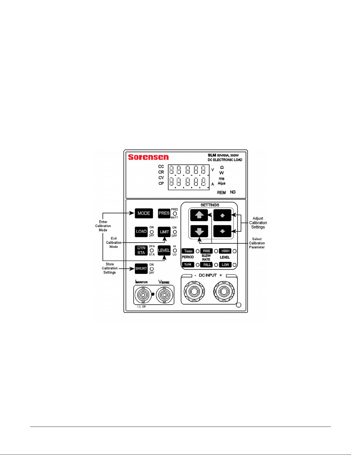
OPERATION DESCRIPTION
This section provides a brief orientation for how to enter, navigate, adjust and
store settings, and exit the calibration mode.
Figure 1-1. SLM Series Front Panel
SLM/SLH Calibration Manual 1-1
Operation Description Elgar Electronics Corporation
1.1 NAVIGATION AND SETTING
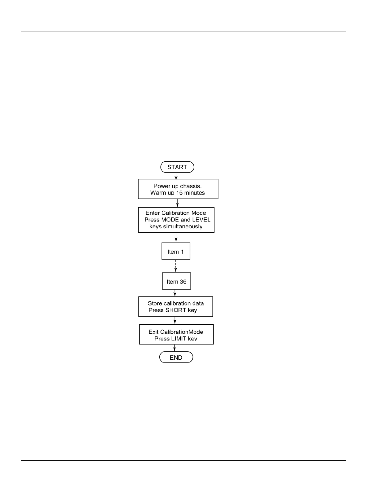
1. Press MODE and LEVEL keys simultaneously to enter calibration mode.
2. Press © (large up arrow) key to move to the next item.
3. Press ª (large down arrow) key to move to the previous item.
4. Press (smaller arrow) keys to adjust the calibration settings.
5. Press the SHORT key to store the calibration settings.
6. Press the LIMIT key to exit the calibration mode.
1.1.1 CALIBRATION PROCEDURE FLOW CHART
1-2 SLM/SLH Calibration Manual
2.1 CALIBRATION SETUP
Prior to starting the calibration procedure, gather the necessary equipment
(Section
minutes.
2.1.1 EQUIPMENT REQUIRED
2.1.1), then power up the chassis and allow it to warm up for 15
• DC Voltage Standard: Krohn-Hite EDC 521
• Current Shunt: Prodigit 7550
SECTION 2
CALIBRATION
• Digital Multi-Meter (DMM): Agilent 34401A
• DC Power Supply: Sorensen SG Series (Supply depends upon
models being calibrated.)
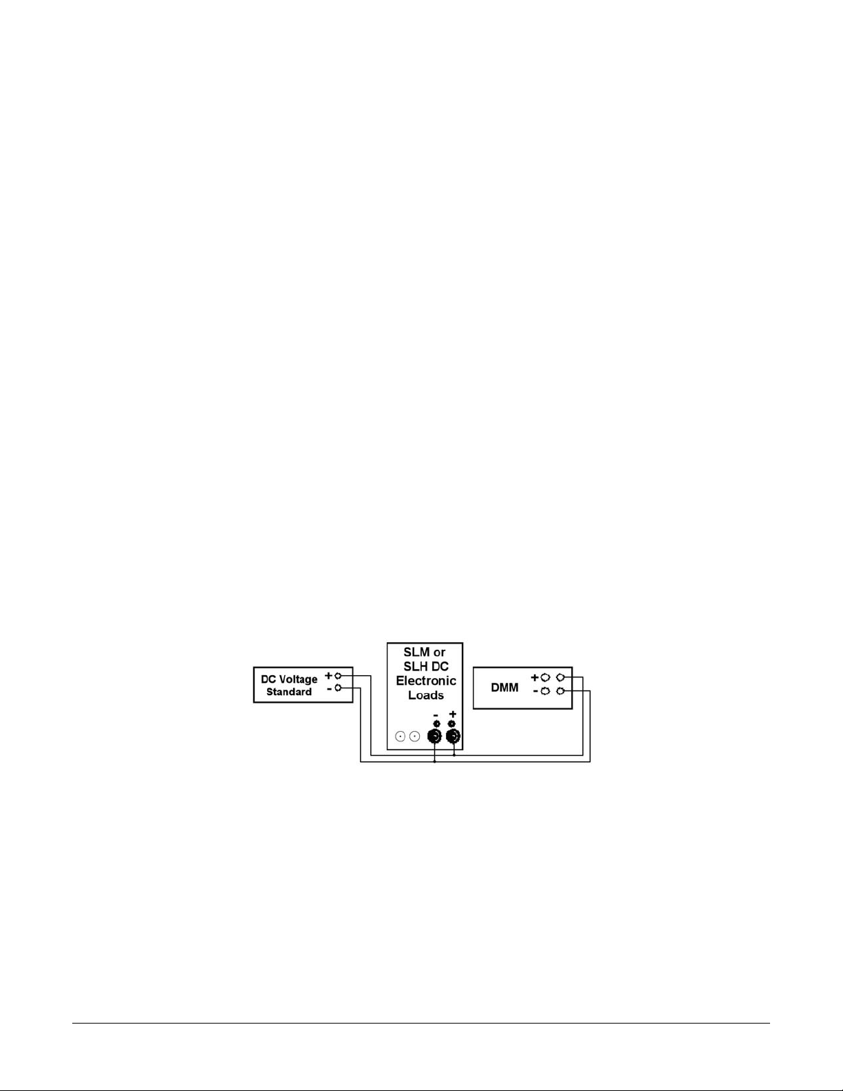
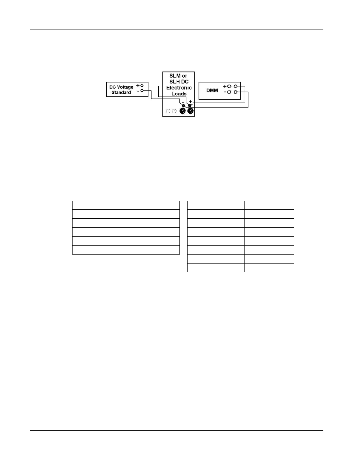
2.2 DVM CALIBRATION
Connect the SL Series electronic load as shown in Figure 2-1
Figure 2-1. Connections for DVM Calibration Items 1-4)
Press MODE and LEVEL keys simultaneously to enter Calibration Mode and
to be at Item 1 to start calibration.
SLM/SLH Calibration Manual 2-1
Calibration Elgar Electronics Corporation
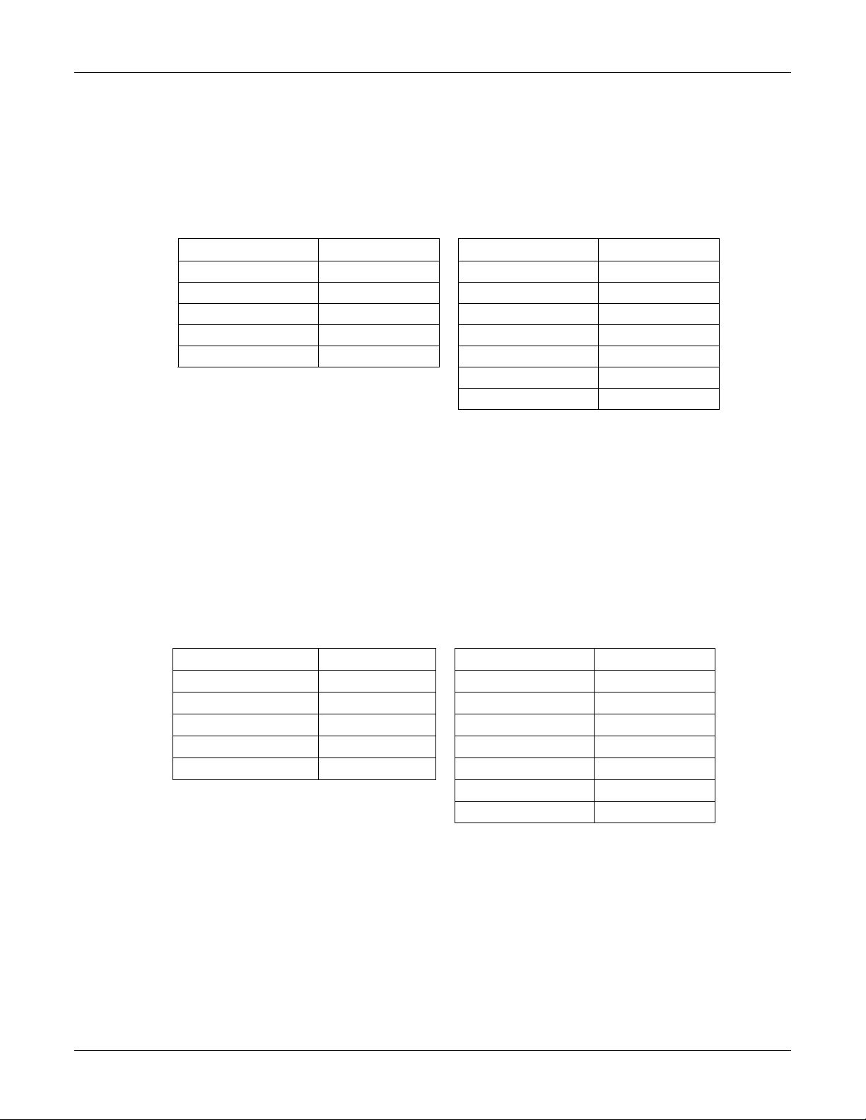
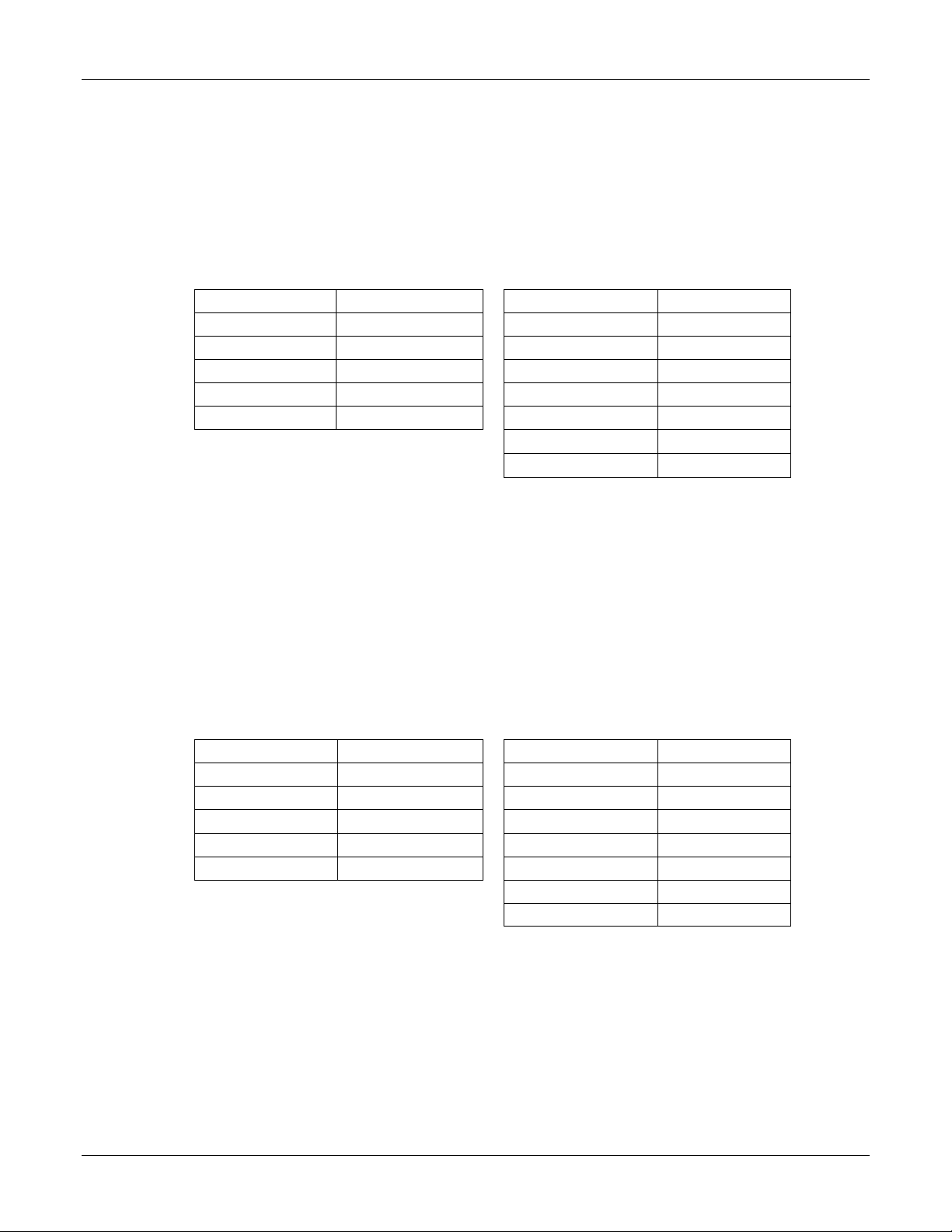
2.2.1 DVM, RANGE I OFFSET AND GAIN, ITEMS 1 AND 2
7. Set the DC Voltage Standard to the Input Voltage value shown in
Table 2-1 for the load model being calibrated.
8. Use the keys to adjust the load DVM display until it matches the
DMM reading.
MODEL MODEL
Input Voltage Input Voltage
SLM-60-30-150 0.200V SLH-60-120-600 0.200V
SLM-60-60-300 0.200V SLH-60-120-1200 0.200V
SLM-250-10-300 0.200V SLH-60-120-1800 0.200V
SLM-500-10-300 0.400V SLH-60-240-1200 0.200V
SLM-60-15-75 0.200V SLH-60-240-1800 0.200V
Table 2-1. DVM, Range I Offset Adjustment Settings (Item 1)
9.
Press the © key to go to Item 2.
10. Set the DC Voltage Standard to the Input Voltage value shown in
Table 2-2 for the load model being calibrated.
11. Use the keys to adjust the load DVM display until it matches the
DMM reading.
12. Repeat steps 1 through 5 (press ª to return to Item 1) until no further
adjustments are necessary for the load DVM to match the DMM
reading.
MODEL MODEL
Input Voltage Input Voltage
SLH-60-360-1800 0.200V
SLH-500-60-1800 0.400V
SLM-60-30-150 15.00V SLH-60-120-600 15.00V
SLM-60-60-300 15.00V SLH-60-120-1200 15.00V
SLM-250-10-300 30.00V SLH-60-120-1800 15.00V
SLM-500-10-300 60.00V SLH-60-240-1200 15.00V
SLM-60-15-75 15.00V SLH-60-240-1800 15.00V
SLH-60-360-1800 15.00V
SLH-500-60-1800 60.00V
Table 2-2. DVM Range I Gain Adjustment Settings (Item 2)
2-2 SLM/SLH Calibration Manual
Elgar Electronics Corporation Calibration
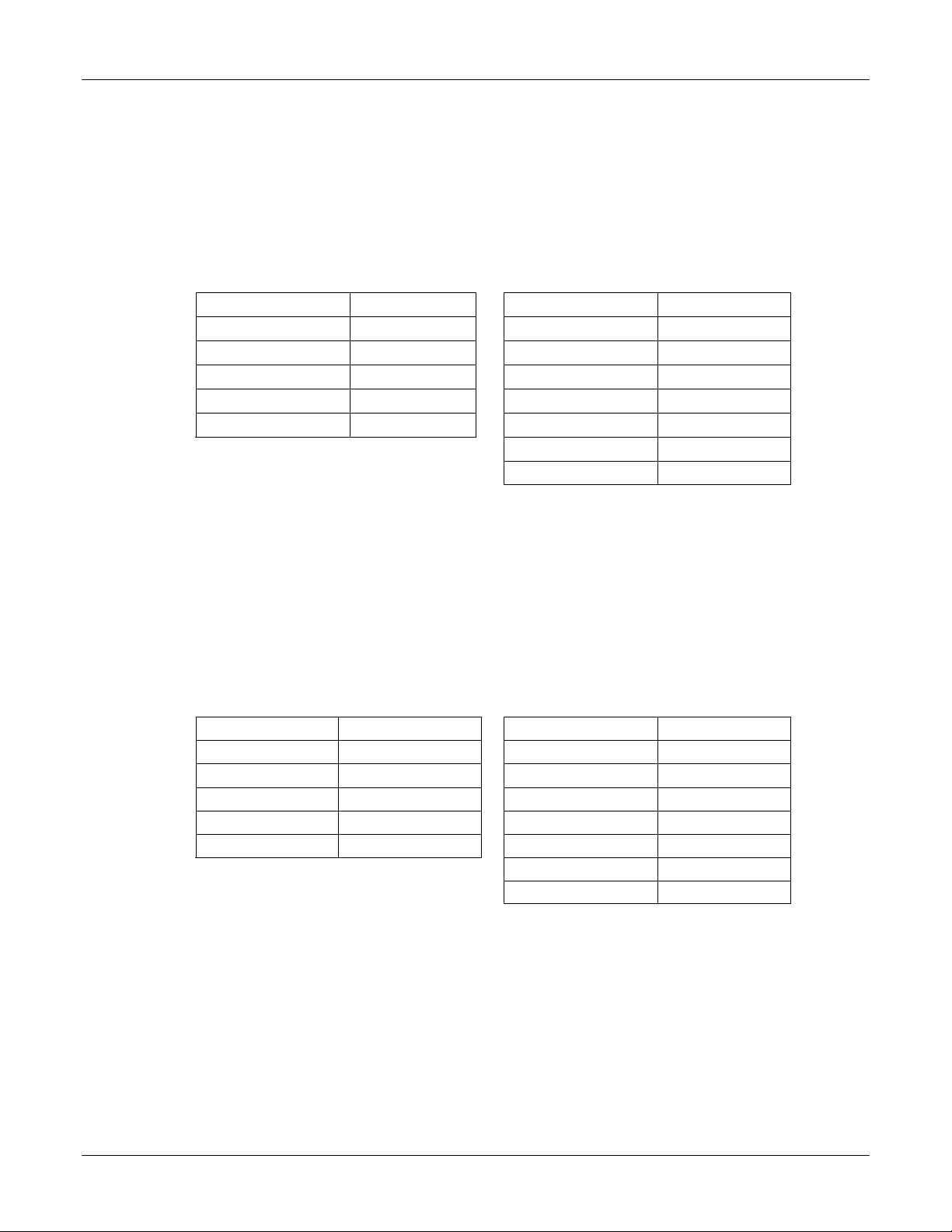
2.2.2 DVM, RANGE II OFFSET AND GAIN, ITEMS 3 AND 4
1. Press the © key to go to Item 3.
2. Set the DC Voltage Standard to the Input Voltage value shown in
Table 2-3 for the model being calibrated.
3. Use the keys to adjust the load DVM display until it matches the
DMM reading.
Item 3 Item 3
Input Voltage Input Voltage
SLM-60-30-150 0.200V SLH-60-120-600 0.200V
SLM-60-60-300 0.200V SLH-60-120-1200 0.200V
SLM-250-10-300 0.200V SLH-60-120-1800 0.200V
SLM-500-10-300 0.400V SLH-60-240-1200 0.200V
SLM-60-15-75 0.200V SLH-60-240-1800 0.200V
Table 2-3. DVM, Range II Gain Adjustment Settings (Item 3)
4.
Press the © key to go to Item 4.
5. Set the DC Voltage Standard to the Input Voltage value shown in
Table 2-4 for the model being calibrated.
6. Use the keys to adjust the load DVM display until it matches the
DMM reading.
7. Repeat steps 1 through 6 (press ª to return to Item 3) until no further
adjustments are necessary for the load DVM to match the DMM
reading.
SLH-60-360-1800 0.200V
SLH-500-60-1800 0.400V
MODEL Input Voltage MODEL Input Voltage
SLM-60-30-150 60.00V SLH-60-120-600 60.00V
SLM-60-60-300 60.00V SLH-60-120-1200 60.00V
SLM-250-10-300 250.00V SLH-60-120-1800 60.00V
SLM-500-10-300 500.00V SLH-60-240-1200 60.00V
SLM-60-15-75 60.00V SLH-60-240-1800 60.00V
SLH-60-360-1800 60.00V
SLH-500-60-1800 500.00V
Table 2-4. DVM, Range II Gain Adjustment Settings (Item 4)
SLM/SLH Calibration Manual 2-3
Calibration Elgar Electronics Corporation
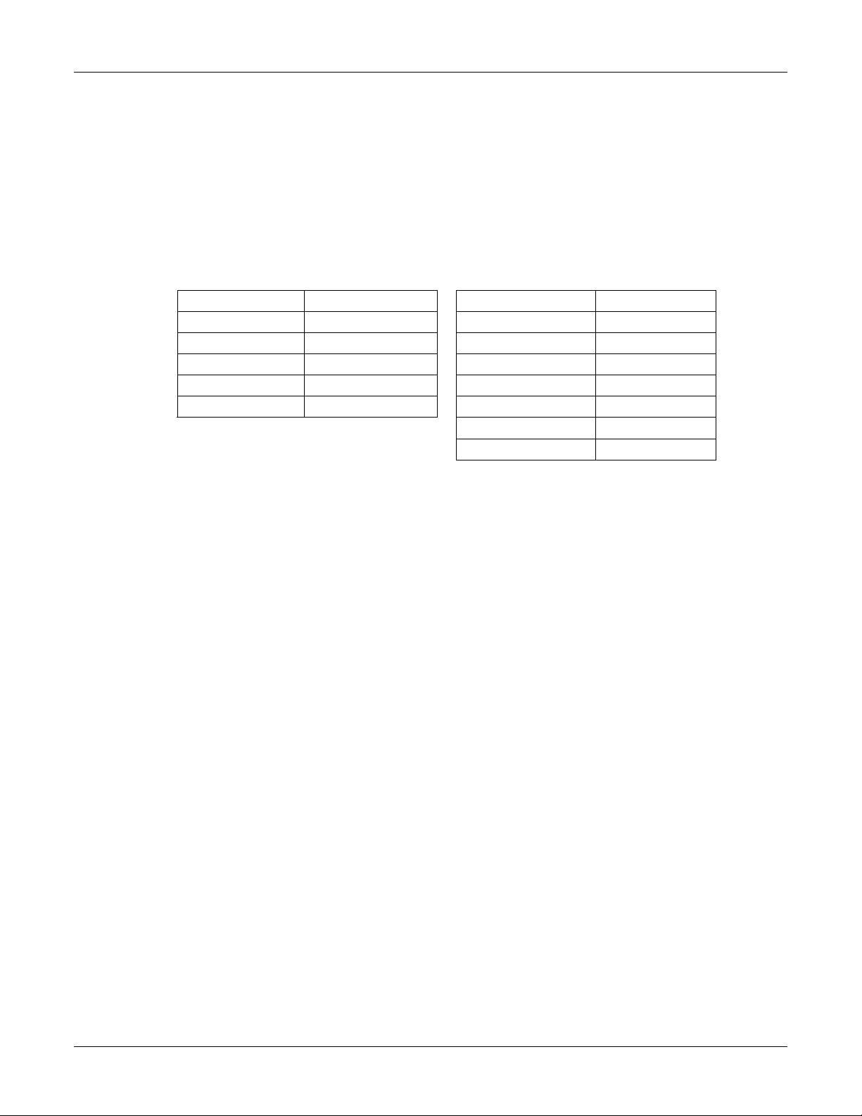
2.3 VSENSE CALIBRATION
Make the connections for VSENSE calibration as shown in Figure 2-2.
Figure 2-2. Connections for Vsense Calibration (Items 5-8).
2.3.1 VSENSE, RANGE I OFFSET AND GAIN, ITEMS 5 AND 6
1. Press the © key to go to Item 5.
2. Set the DC Voltage Standard to the Input Voltage value shown in
Table 2-5 for the model being calibrated.
3. Use the keys to adjust the load DVM display until it matches the
DMM reading.
MODEL Input Voltage MODEL Input Voltage
SLM-60-30-150 0.200V SLH-60-120-600 0.200V
SLM-60-60-300 0.200V SLH-60-120-1200 0.200V
SLM-250-10-300 0.200V SLH-60-120-1800 0.200V
SLM-500-10-300 0.400V SLH-60-240-1200 0.200V
SLM-60-15-75 0.200V SLH-60-240-1800 0.200V
Table 2-5. VSense, Range I Offset Adjustment Settings (Item 5)
4. Press the © key to go to Item 6.
SLH-60-360-1800 0.200V
SLH-500-60-1800 0.400V
2-4 SLM/SLH Calibration Manual
Elgar Electronics Corporation Calibration
5. Set the DC Voltage Standard to the Input Voltage value shown in
Table 2-6 for the model being calibrated.
6. Use the keys to adjust the load DVM display until it matches the
DMM reading.
7. Repeat steps 1 through 6 (press ª to return to Item 5) until no further
adjustments are necessary for the load DVM to match the DMM
reading.
MODEL MODEL
SLM-60-30-150 15.00V
SLM-60-60-300 15.00V
SLM-250-10-300 30.00V
SLM-500-10-300 60.00V
SLM-60-15-75 15.00V
Table 2-6. VSENSE, Range I Gain Adjustment Settings (Item 6)
Input Voltage Input Voltage
SLH-60-120-600
SLH-60-120-1200
SLH-60-120-1800
SLH-60-240-1200
SLH-60-240-1800
SLH-60-360-1800
SLH-500-60-1800
15.00V
15.00V
15.00V
15.00V
15.00V
15.00V
60.00V
2.3.2 VSENSE, RANGE II OFFSET AND GAIN, ITEMS 7 AND 8
1. Press the © key to go to Item 7.
2. Set the DC Voltage Standard to the Input Voltage value shown in Table
2-7
for the model being calibrated.
3. Use the keys to adjust the load DVM display until it matches the
DMM reading.
MODEL Input Voltage MODEL Input Voltage
SLM-60-30-150 0.200V SLH-60-120-600 0.200V
SLM-60-60-300 0.200V SLH-60-120-1200 0.200V
SLM-250-10-300 0.200V SLH-60-120-1800 0.200V
SLM-500-10-300 0.400V SLH-60-240-1200 0.200V
SLM-60-15-75 0.200V SLH-60-240-1800 0.200V
SLH-60-360-1800 0.200V
SLH-500-60-1800 0.400V
Table 2-7. VSENSE, Range II Offset Adjustment Settings (Item 7)
4.
Press the © key to go to Item 8.
SLM/SLH Calibration Manual 2-5
Calibration Elgar Electronics Corporation
5. Set the DC Voltage Standard to the Input Voltage value shown in Table
2-8
for the model being calibrated.
6. Use the keys to adjust the load DVM display until it matches the
DMM reading.
7. Repeat steps 1 through 6 (press ª to return to Item 7) until no further
adjustments are necessary for the DVM display to match the DMM
reading.
MODEL Input Voltage MODEL Input Voltage
SLM-60-30-150 60.00V SLH-60-120-600 60.00V
SLM-60-60-300 60.00V SLH-60-120-1200 60.00V
SLM-250-10-300 250.00V SLH-60-120-1800 60.00V
SLM-500-10-300 500.00V SLH-60-240-1200 60.00V
SLM-60-15-75 60.00V SLH-60-240-1800 60.00V
SLH-60-360-1800 60.00V
SLH-500-60-1800 500.00V
Table 2-8. VSense, Range II Gain Adjustment Settings (Item 8)
2-6 SLM/SLH Calibration Manual

Elgar Electronics Corporation Calibration
2.4 DAM AND CC MODE CALIBRATIONS
The following three steps apply to both DAM and CC Mode Calibration, Items
9-20:
1. Connect the DC Power supply to input terminal, as shown in Figure
2-3
.
2. Set the power supply voltage to +5Vdc.
Figure 2-3. Connections for DAM and CC Mode Calibrations
2.4.1 DAM, RANGE I OFFSET AND GAIN, ITEMS 9 AND 10
1. Press the © key to go to Item 9.
2. LOAD OFF.
3. PRES ON.
4. Set the load current as shown in Table 2-9 for the model being
calibrated.
5. PRES OFF.
6. LOAD ON.
7. Adjust using the keys until the load DAM reading matches the
DMM reading.
MODEL Current Setting MODEL Current Setting
SLM-60-30-150 0.00A SLH-60-120-600 0.00A
SLM-60-60-300 0.00A SLH-60-120-1200 0.00A
SLM-250-10-300 0.00A SLH-60-120-1800 0.00A
SLM-500-10-300 0.00A SLH-60-240-1200 0.00A
SLM-60-15-75 0.00A SLH-60-240-1800 0.00A
SLH-60-360-1800 0.00A
SLH-500-60-1800 0.00A
Table 2-9. DAM, Range I Offset Adjustment Settings (Item 9)
SLM/SLH Calibration Manual 2-7

Calibration Elgar Electronics Corporation
8. LOAD OFF.
9. Press the © key to go to Item 10.
10. PRES ON.
11. Set the load current as shown in Table 2-10 for the model being
calibrated.
12. PRES OFF.
13. LOAD ON.
14. Adjust using the keys until the shunt current and the load DAM
reading match.
15. Repeat steps 1 through 14 (press ª to return to Item 9) until no
further adjustments are necessary for the load DAM to match the
DMM reading.
MODEL Current Setting MODEL Current Setting
SLM-60-30-150 3.000A SLH-60-120-600 12.00A
SLM-60-60-300 6.000A SLH-60-120-1200 12.00A
SLM-250-10-300 1.0050A SLH-60-120-1800 12.00A
SLM-500-10-300 1.0050A SLH-60-240-1200 24.00A
SLM-60-15-75 1.500A SLH-60-240-1800 24.00A
SLH-60-360-1800 36.00A
SLH-500-60-1800 6.000A
Table 2-10. DAM, Range I Gain Adjustment Settings (Item 10)
2-8 SLM/SLH Calibration Manual

Elgar Electronics Corporation Calibration
2.4.2 DAM, RANGE II OFFSET AND GAIN, ITEMS 11 AND 12
1. LOAD OFF.
2. Press the © key to go to Item 11.
3. PRES ON.
4. Set the load current as shown in Table 2-11 for the model being
calibrated.
5. PRES OFF.
6. LOAD ON.
7. Adjust using the keys until the load DAM matches the DMM
reading.
MODEL Current Setting MODEL Current Setting
SLM-60-30-150 0.00A SLH-60-120-600 0.00A
SLM-60-60-300 0.00A SLH-60-120-1200 0.00A
SLM-250-10-300 0.00A SLH-60-120-1800 0.00A
SLM-500-10-300 0.00A SLH-60-240-1200 0.00A
SLM-60-15-75 0.00A SLH-60-240-1800 0.00A
SLH-60-360-1800 0.00A
SLH-500-60-1800 0.00A
Table 2-11. DAM, Range II Offset Adjustment Settings (Item 11)
8.
Load OFF.
9. Press the © key to go to Item 12.
SLM/SLH Calibration Manual 2-9

Calibration Elgar Electronics Corporation
10. PRES ON.
11. Set the load current as shown in Table 2-12 for the model being
calibrated.
12. PRES OFF.
13. LOAD ON.
14. Adjust using the keys until the shunt current and the load DAM
reading match.
15. Repeat steps 1 through 14 (press ª to return to Item 11) until no
further adjustments are necessary for the load DAM to match the
DMM reading.
MODEL Current Setting MODEL Current Setting
SLM-60-30-150 30.00A SLH-60-120-600 120.00A
SLM-60-60-300 60.00A SLH-60-120-1200 120.00A
SLM-250-10-300 10.050A SLH-60-120-1800 120.00A
SLM-500-10-300 10.050A SLH-60-240-1200 240.00A
SLM-60-15-75 15.000A SLH-60-240-1800 240.00A
SLH-60-360-1800 360.00A
SLH-500-60-1800 60.00A
Table 2-12. DAM, Range II Gain Adjustment Settings (Item 12)
2.4.3 CC MODE, LEVEL LOW, RANGE I OFFSET AND GAIN, ITEMS 13 AND 14
1. LOAD OFF (Power supply voltage should still be at +5Vdc).
2. Press the © key to go to Item 13.
3. PRES ON.
4. Set the load current as shown in Table 2-13 for the model being
calibrated.
5. PRES OFF.
6. LOAD ON.
7. Adjust using the keys until the shunt current and the current
setting match.
MODEL Current Setting MODEL Current Setting
SLM-60-30-150 0.00A SLH-60-120-600 0.00A
SLM-60-60-300 0.00A SLH-60-120-1200 0.00A
SLM-250-10-300 0.00A SLH-60-120-1800 0.00A
SLM-500-10-300 0.00A SLH-60-240-1200 0.00A
SLM-60-15-75 0.00A SLH-60-240-1800 0.00A
SLH-60-360-1800 0.00A
SLH-500-60-1800 0.00A
Table 2-13. CC Mode, Level Low, Range I Offset Adjustment Settings (Item 13)
2-10 SLM/SLH Calibration Manual

Elgar Electronics Corporation Calibration
8. LOAD OFF.
9. Press the © key to go to Item 14.
10. PRES ON.
11. Set the load current as shown in Table 2-16 for the model being
calibrated.
12. PRES OFF.
13. LOAD ON.
14. Adjust using the keys until the shunt current and the current
setting match.
15. Repeat steps 1 through 14 (press ª to return to Item 13) until no
further adjustments are necessary for the shunt current and the
current setting to match.
MODEL Current Setting MODEL Current Setting
SLM-60-30-150 3.000A SLH-60-120-600 12.00A
SLM-60-60-300 6.000A SLH-60-120-1200 12.00A
SLM-250-10-300 1.0050A SLH-60-120-1800 12.00A
SLM-500-10-300 1.0050A SLH-60-240-1200 24.00A
SLM-60-15-75 1.500A SLH-60-240-1800 24.00A
SLH-60-360-1800 36.00A
SLH-500-60-1800 6.000A
Table 2-14. CC Mode, Level Low, Range I Gain Adjustment Settings (Item 14)
SLM/SLH Calibration Manual 2-11

Calibration Elgar Electronics Corporation
2.4.4 CC MODE, LEVEL HIGH, RANGE I OFFSET AND GAIN, ITEMS 15 AND 16
1. LOAD OFF.
2. Press the © key to go to Item 15.
3. PRES ON.
4. Set the load current as shown in Table 2-15 for the model being
calibrated.
5. PRES OFF.
6. LOAD ON.
7. Adjust using the keys until the shunt current and the current
setting match.
MODEL Current Setting MODEL Current Setting
SLM-60-30-150 0.00A SLH-60-120-600 0.00A
SLM-60-60-300 0.00A SLH-60-120-1200 0.00A
SLM-250-10-300 0.00A SLH-60-120-1800 0.00A
SLM-500-10-300 0.00A SLH-60-240-1200 0.00A
SLM-60-15-75 0.00A SLH-60-240-1800 0.00A
SLH-60-360-1800 0.00A
SLH-500-60-1800 0.00A
Table 2-15. CC Mode, Level High, Range I Offset Adjustment Settings (Item 15)
8.
LOAD OFF.
9. Press the © key to go to Item 16.
10. PRES ON.
11. Set the load current as shown in Table 2-16 for the model being
calibrated.
12. PRES OFF.
13. LOAD ON.
14. Adjust using the keys until the shunt current and the current
setting match.
15. Repeat steps 1 through 14 (press ª to return to Item 15) until no
further adjustments are necessary for the shunt current and the
current setting to match.
2-12 SLM/SLH Calibration Manual

Elgar Electronics Corporation Calibration
16. PRES ON.
17. Set the load current as shown in Table 2-16 for the model being
calibrated.
18. PRES OFF.
19. LOAD ON.
20. Adjust using the keys until the shunt current and the current
setting match.
21. Repeat steps 1 through 14 (press ª to return to Item 15) until no
further adjustments are necessary for the shunt current and the
current setting to match.
MODEL MODEL Current Setting
Current
Setting
SLM-60-30-150 3.000A SLH-60-120-600 12.00A
SLM-60-60-300 6.000A SLH-60-120-1200 12.00A
SLM-250-10-300 1.0050A SLH-60-120-1800 12.00A
SLM-500-10-300 1.0050A SLH-60-240-1200 24.00A
SLM-60-15-75 1.500A SLH-60-240-1800 24.00A
Table 2-16. CC Mode, Level High, Range I Gain Adjustment Settings (Item 16)
SLH-60-360-1800 36.00A
SLH-500-60-1800 6.000A
2.4.5 CC MODE, LEVEL LOW, RANGE II OFFSET AND GAIN, ITEMS 17 AND 18
1. LOAD OFF.
2. Press the © key to go to Item 17.
3. PRES ON.
4. Set the load current as shown in Table 2-17 for the model being
calibrated.
5. PRES OFF.
6. LOAD ON.
7. Adjust using the keys until the shunt current and the current
setting match.
MODEL Current Setting MODEL Current Setting
SLM-60-30-150 0.00A SLH-60-120-600 0.00A
SLM-60-60-300 0.00A SLH-60-120-1200 0.00A
SLM-250-10-300 0.00A SLH-60-120-1800 0.00A
SLM-500-10-300 0.00A SLH-60-240-1200 0.00A
SLM-60-15-75 0.00A SLH-60-360-1800 0.00A
SLH-500-60-1800 0.00A
Table 2-17. CC Mode, Level Low, Range II Offset Adjustment Settings (Item 17)
SLM/SLH Calibration Manual 2-13

Calibration Elgar Electronics Corporation
8. LOAD OFF.
9. Press the © key to go to Item 18.
10. PRES ON.
11. Set the load current as shown in Table 2-18 for the model being
calibrated.
12. PRES OFF.
13. LOAD ON.
14. Adjust using the keys until the shunt current and the current
setting match.
15. Repeat steps 1 through 14 (press ª to return to Item 17) until no
further adjustments are necessary for the shunt and the current
setting to match.
MODEL Current Setting MODEL Current Setting
SLM-60-30-150 30.00A SLH-60-120-600 120.00A
SLM-60-60-300 60.00A SLH-60-120-1200 120.00A
SLM-250-10-300 10.050A SLH-60-120-1800 120.00A
SLM-500-10-300 10.050A SLH-60-240-1200 240.00A
SLM-60-15-75 15.000A SLH-60-240-1800 240.00A
SLH-60-360-1800 360.00A
SLH-500-60-1800 60.00A
Table 2-18. CC Mode, Level Low, Range II Gain Adjustment Settings (Item 18)
2-14 SLM/SLH Calibration Manual

Elgar Electronics Corporation Calibration
2.4.6 CC MODE, LEVEL HIGH, RANGE II OFFSET AND GAIN, ITEMS 19 AND 20
1. LOAD OFF.
2. Press the © key to go to Item 19.
3. PRES ON.
4. Set the load current as shown in Table 2-19 for the model being
calibrated.
5. PRES OFF.
6. LOAD ON.
7. Adjust using the keys until the shunt current and the current
setting match.
MODEL Current Setting MODEL Current Setting
SLM-60-30-150 0.00A SLH-60-120-600 0.00A
SLM-60-60-300 0.00A SLH-60-120-1200 0.00A
SLM-250-10-300 0.00A SLH-60-120-1800 0.00A
SLM-500-10-300 0.00A SLH-60-240-1200 0.00A
SLM-60-15-75 0.00A SLH-60-240-1800 0.00A
SLH-60-360-1800 0.00A
SLH-500-60-1800 0.00A
Table 2-19. CC Mode, Level High, Range II Offset Adjustment Settings (Item 19)
8.
LOAD OFF.
9. Press the © key to go to Item 20.
SLM/SLH Calibration Manual 2-15

Calibration Elgar Electronics Corporation
10. PRES ON.
11. Set the load current as shown in Table 2-20 for the model being
calibrated.
12. PRES OFF.
13. LOAD ON.
14. Adjust using the keys until the shunt current and the current
setting match.
15. Repeat steps 1 through 14 (press ª to return to Item 19) until no
further adjustments are necessary for the shunt current and the
current setting to match.
MODEL Current Setting MODEL Current Setting
SLM-60-30-150 30.00A SLH-60-120-600 120.00A
SLM-60-60-300 60.00A SLH-60-120-1200 120.00A
SLM-250-10-300 10.050A SLH-60-120-1800 120.00A
SLM-500-10-300 10.050A SLH-60-240-1200 240.00A
SLM-60-15-75 15.000A SLH-60-240-1800 240.00A
SLH-60-360-1800 360.00A
SLH-500-60-1800 60.00A
Table 2-20. CC Mode, Level High, Range II Gain Adjustment Settings (Item 20)
2.5 CR MODE CALIBRATION
Connect the DC Power supply and DC Voltage Standard, as shown in
Figure 2-4.
Figure 2-4. Connections for CR Mode Calibration
2-16 SLM/SLH Calibration Manual

Elgar Electronics Corporation Calibration
2.5.1 CR MODE, LEVEL LOW, RANGE I OFFSET AND GAIN, ITEMS 21 AND 22
1. LOAD OFF.
2. Press the © key to go to Item 21.
3. Set the power supply voltage and the DC Voltage Standard to the
VSENSE Input value shown in
calibrated.
4. PRES ON
5. Set the current to the Current Setting value in Table 2-21 for the
model being calibrated.
6. PRES OFF.
7. LOAD ON.
8. Adjust using the keys until the DAM reading and the current
setting match.
Table 2-21 for the model being
MODEL Resistance Setting VSENSE Input Current Setting
SLM-60-30-150 3750 Ω 60.00V 0.016A
SLM-60-60-300 3750 Ω 60.00V 0.016A
SLM-250-10-300 15625 Ω 250.00V 0.016A
SLM-500-10-300 6250 Ω 500.0V 0.08A
SLM-60-15-75 5000 Ω 60.00V 0.012A
SLH-60-120-600 1875 Ω 60.00V 0.0320A
SLH-60-120-1200 1875 Ω 60.00V 0.0320A
SLH-60-120-1800 1875 Ω 60.00V 0.0320A
SLH-60-240-1200 937.50 Ω 60.00V 0.0640A
SLH-60-240-1800 937.50 Ω 60.00V 0.0640A
SLH-60-360-1800 625 Ω 60.00V 0.0960A
SLH-500-60-1800 15625. Ω 500.00V 0.0320A
Table 2-21. CR Mode, Level Low, Range I Offset Adjustment Settings (Item 21)
LOAD OFF.
9.
10. Press the © key to go to Item 22.
SLM/SLH Calibration Manual 2-17

Calibration Elgar Electronics Corporation
11. Set the power supply voltage and the DC Voltage Standard to the
VSENSE Input value shown in
calibrated.
12. PRES ON.
13. Set the current to the Current Setting value in Table 2-22 for the
model being calibrated.
14. PRES OFF.
15. LOAD ON.
16. Adjust using the keys until the DAM reading and the current
setting match.
17. Repeat steps 1 through 16 (press ª to return to Item 21) until no
further adjustments are necessary for the DAM reading t and the
current setting to match.
Table 2-22 for the model being
MODEL Resistance Setting VSENSE Input Current Setting
SLM-60-30-150 2.000 Ω 60.00V 30.00A
SLM-60-60-300 1.000Ω 60.00V 60.00A
SLM-250-10-300 25.00Ω 250.00V 10.00A
SLM-500-10-300 50.00Ω 500.00V 10.000A
SLM-60-15-75 4.000Ω 60.00V 15.000A
SLH-60-120-600 0.5000 Ω 60.00V 120.00A
SLH-60-120-1200 0.5000 Ω 60.00V 120.00A
SLH-60-120-1800 0.5000 Ω 60.00V 120.00A
SLH-60-240-1200 0.2500 Ω 60.00V 240.00A
SLH-60-240-1800 0.2500 Ω 60.00V 240.00A
SLH-60-360-1800 0.167 Ω 60.00V 359.281A
SLH-500-60-1800 8.3333 Ω 500.00V 60.00A
Table 2-22. CR Mode, Level Low, Range I Gain Adjustment Settings (Item 22)
2-18 SLM/SLH Calibration Manual

Elgar Electronics Corporation Calibration
2.5.2 CR MODE, LEVEL HIGH, RANGE I OFFSET AND GAIN ITEMS 23 AND 24
1. LOAD OFF.
2. Press the © key to go to Item 23.
3. Set the power supply voltage and the DC Voltage Standard to the
VSENSE Input value shown in
calibrated.
4. PRES ON.
5. Set the current to the Current Setting value in Table 2-23 for the
model being calibrated.
6. PRES OFF.
7. LOAD ON.
8. Adjust using the keys until the DAM reading and the current
setting match.
Table 2-23 for the model being
MODEL Resistance Setting VSENSE Input Current Setting
SLM-60-30-150 3750 Ω 60.00V 0.016A
SLM-60-60-300 3750 Ω 60.00V 0.016A
SLM-250-10-300 15625 Ω 250.00V 0.08A
SLM-500-10-300 6250 Ω 500.0V 0.04A
SLM-60-15-75 5000 Ω 60.00V 0.012A
SLH-60-120-600 1875 Ω 60.00V 0.0320A
SLH-60-120-1200 1875 Ω 60.00V 0.0320A
SLH-60-120-1800 1875 Ω 60.00V 0.0320A
SLH-60-240-1200 937.50 Ω 60.00V 0.0640A
SLH-60-240-1800 937.50 Ω 60.00V 0.0640A
SLH-60-360-1800 625 Ω 60.00V 0.0960A
SLH-500-60-1800 15625. Ω 500.00V 0.032A
Table 2-23. CR Mode, Level High, Range I Offset Adjustment Settings (Item 23)
9. LOAD OFF.
10. Press the © key to go to Item 24.
SLM/SLH Calibration Manual 2-19

Calibration Elgar Electronics Corporation
11. Set the power supply voltage and the DC Voltage Standard to the
VSENSE Input value shown in
calibrated.
12. PRES ON.
13. Set the current to the Current Setting value in Table 2-24 for the
model being calibrated.
14. PRES OFF.
15. LOAD ON.
16. Adjust using the keys until the DAM reading and the current
setting match.
17. Repeat steps 1 through 16 (press ª to return to Item 23) until no
further adjustments are necessary for the DAM reading t and the
current setting to match.
Table 2-24 for the model being
MODEL Resistance Setting VSENSE Input Current Setting
SLM-60-30-150 2.000 Ω 60.00V 30.00A
SLM-60-60-300 1.000Ω 60.00V 60.00A
SLM-250-10-300 25.00Ω 250.00V 10.00A
SLM-500-10-300 50.00Ω 500.00V 10.000A
SLM-60-15-75 4.000Ω 60.00V 15.000A
SLH-60-120-600 0.5000 Ω 60.00V 120.00A
SLH-60-120-1200 0.5000 Ω 60.00V 120.00A
SLH-60-120-1800 0.5000 Ω 60.00V 120.00A
SLH-60-240-1200 0.2500 Ω 60.00V 240.00A
SLH-60-240-1800 0.2500 Ω 60.00V 240.00A
SLH-60-360-1800 0.167 Ω 60.00V 359.281A
SLH-500-60-1800 8.333 Ω 500.00V 60.00A
Table 2-24. CR Mode, Level High, Range I Gain Adjustment Settings (Item 24)
2-20 SLM/SLH Calibration Manual

Elgar Electronics Corporation Calibration
2.5.3 CR MODE, LEVEL LOW, RANGE II OFFSET AND GAIN, ITEMS 25 AND 26
1. LOAD OFF.
2. Press the © key to go to Item 25.
3. Set the power supply voltage and the DC Voltage Standard to the
VSENSE Input value shown in
calibrated.
4. PRES ON.
5. Set the current to the Current Setting value in Table 2-25 for the
model being calibrated.
6. PRES OFF.
7. LOAD ON.
8. Adjust using the keys until the DAM reading and the current
setting match.
Table 2-25 for the model being
MODEL Resistance Setting VSENSE Input Current Setting
SLM-60-30-150 0.1068Ω 3.204V 30.00A
SLM-60-60-300 0.0534Ω 3.204V 60.00A
SLM-250-10-300 1.3334Ω 13.334V 10.00A
SLM-500-10-300 2.680Ω 26.80V 10.000A
SLM-60-15-75 0.2134Ω 3.201V 15.00A
SLH-60-120-600 0.0268 Ω 3.216V 120.00A
SLH-60-120-1200 0.0268 Ω 3.216V 120.00A
SLH-60-120-1800 0.0268 Ω 3.216V 120.00A
SLH-60-240-1200 0.0133 Ω 3.216V 240.00A
SLH-60-240-1800 0.0134 Ω 3.216V 240.00A
SLH-60-360-1800 0.0088 Ω 3.168V 360.00A
SLH-500-60-1800 0.4444Ω 26.666V 60.00A
Table 2-25. CR Mode, Level Low, Range II Offset Adjustment Settings (Item 25)
9.
LOAD OFF.
10. Press the © key to go to Item 26.
SLM/SLH Calibration Manual 2-21

Calibration Elgar Electronics Corporation
11. Set the power supply voltage and the DC Voltage Standard to the
VSENSE Input value shown in
calibrated.
12. PRES ON.
13. Set the current to the Current Setting value in Table 2-26 for the
model being calibrated.
14. PRES OFF.
15. LOAD ON.
16. Adjust using the keys until the DAM reading and the current
setting match.
17. Repeat steps 1 through 16 (press ª to return to Item 25) until no
further adjustments are necessary for the DAM reading and the
current setting to match.
Table 2-26 for the model being
MODEL Resistance Setting VSENSE Input Current Setting
SLM-60-30-150
SLM-60-60-300
SLM-250-10-300
SLM-500-10-300
SLM-60-15-75
2.003Ω 60.00V 30.00A
1.001Ω 60.00V 60.00A
25.00Ω 250.00V 10.000A
50.00Ω 500.00V 10.000A
4.000Ω 60.00V 15.000A
SLH-60-120-600
SLH-60-120-1200
SLH-60-120-1800
SLH-60-240-1200
SLH-60-240-1800
SLH-60-360-1800
SLH-500-60-1800
Table 2-26. CR Mode, Level Low, Range II Gain Adjustment Settings (Item 26)
0.5000 Ω 60.00V 120.00A
0.5000 Ω 60.00V 120.00A
0.5000 Ω 60.00V 120.00A
0.2500 Ω 60.00V 240.00A
0.2500 Ω 60.00V 240.00A
0.167 Ω 60.00V 359.281A
8.3333Ω 500.00V 60.00A
2-22 SLM/SLH Calibration Manual

Elgar Electronics Corporation Calibration
2.5.4 CR MODE, LEVEL HIGH, RANGE II OFFSET AND GAIN, ITEMS 27 AND 28
1. LOAD OFF.
2. Press the © key to go to Item 27.
3. Set the power supply voltage and the DC Voltage Standard to the
VSENSE Input value shown in
calibrated.
4. PRES ON.
5. Set the current to the Current Setting value in Table 2-27 for the
model being calibrated.
6. PRES OFF.
7. LOAD ON.
8. Adjust using the keys until the DAM reading and the current
setting match.
Table 2-27 for the model being
MODEL
Resistance Setting VSENSE Input Current Setting
SLM-60-30-150 0.1068Ω 3.204V 30.000A
SLM-60-60-300 0.0534Ω 3.204V 60.000A
SLM-250-10-300 1.3334Ω 13.334V 10.000A
SLM-500-10-300 2.680Ω 26.80V 5.000A
SLM-60-15-75 0.2134Ω 3.201V 15.000A
SLH-60-120-600 0.0268 Ω 3.216V 120.00A
SLH-60-120-1200 0.0268 Ω 3.216V 120.00A
SLH-60-120-1800 0.0268 Ω 3.216V 120.00A
SLH-60-240-1200 0.0133 Ω 3.216V 240.00A
SLH-60-240-1800 0.0134 Ω 3.216V 240.00A
SLH-60-360-1800 0.0088 Ω 3.168V 360.00A
SLH-500-60-1800 0.4444Ω 26.666V 60.00A
Table 2-27. CR Mode, Level High, Range II Offset Adjustment Settings (Item 27)
9.
LOAD OFF.
10. Press the © key to go to Item 28.
SLM/SLH Calibration Manual 2-23

Calibration Elgar Electronics Corporation
11. Set the power supply voltage and the DC Voltage Standard to the
VSENSE Input value shown in
calibrated.
12. PRES ON.
13. Set the current to the Current Setting value in Table 2-28 for the
model being calibrated.
14. PRES OFF.
15. LOAD ON.
16. Adjust using the keys until the DAM reading and the current
setting match.
17. Repeat steps 1 through 16 (press ª to return to Item 27) until no
further adjustments are necessary for the DAM reading and the
current setting to match.
Table 2-28 for the model being
MODEL
Resistance Setting VSENSE Current Setting
SLM-60-30-150 2.000Ω 60.00V 30.000A
SLM-60-60-300 1.0001Ω 60.00V 60.000A
SLM-250-10-300 25.00Ω 250.00V 10.000A
SLM-500-10-300 50.000Ω 500.00V 10.000A
SLM-60-15-75 4.000Ω 60.00V 15.000A
SLH-60-120-600 0.5000 Ω 60.00V 120.00A
SLH-60-120-1200 0.5000 Ω 60.00V 120.00A
SLH-60-120-1800 0.5000 Ω 60.00V 120.00A
SLH-60-240-1200 0.2500 Ω 60.00V 240.00A
SLH-60-240-1800 0.2500 Ω 60.00V 240.00A
SLH-60-360-1800 0.167 Ω 60.00V 359.281A
SLH-500-60-1800 8.3333 Ω 500.00V 60.00A
Table 2-28. CR Mode, Level High, Range II Gain Adjustment Settings (Item 28)
2-24 SLM/SLH Calibration Manual

Elgar Electronics Corporation Calibration
2.6 CV MODE CALIBRATION
Connect the DC Power Supply to the input terminal as illustrated in Figure 1-1.
Figure 2-5. CV Mode Calibration Connections
SLM/SLH Calibration Manual 2-25

Calibration Elgar Electronics Corporation
2.6.1 CV MODE, LEVEL LOW, OFFSET AND GAIN, ITEMS 29 AND 30
For CV Mode Calibration, set the DC power supply current limit to 0.1A.
1. LOAD OFF.
2. Press the © key to go to Item 29.
3. PRES ON.
4. Set the power supply voltage to the V Input value shown in Table 2-29
for the model being calibrated.
5. PRES OFF.
6. LOAD ON.
7. Adjust using the keys until the DVM reading and the Voltage
Setting match.
MODEL V Input Voltage Setting MODEL V Input Voltage Setting
SLM-60-30-150
SLM-60-60-300
SLM-250-10-300
SLM-500-10-300
SLM-60-15-75
61.5V 0.800V SLH-60-120-600 61.5V 0.800V
61.5V 0.800V SLH-60-120-1200 61.5V 0.800V
61.5V 8.000V SLH-60-120-1800 61.5V 0.800V
61.5V 16.008V SLH-60-240-1200 61.5V 0.800V
61.5V 0.800V SLH-60-240-1800 61.5V 0.800V
SLH-60-360-1800 61.5V 0.800V
SLH-500-60-1800
61.5V
16.008V
Table 2-29. CV Mode, Level Low, Offset Adjustment Settings (Item 29)
8. LOAD OFF.
9. Press the © key to go to Item 30.
2-26 SLM/SLH Calibration Manual

Elgar Electronics Corporation Calibration
10. PRES ON.
11. Set voltage to the V Input value shown in Table 2-30 for the model
being calibrated.
12. PRES OFF.
13. LOAD ON.
14. Adjust using the keys until the DVM reading and the Voltage
Setting match.
15. Repeat steps 1 through 14 (press ª to return to Item 29) until no
further adjustments are necessary for the DVM reading and the
Voltage Setting to match.
MODEL V Input Voltage Setting MODEL V Input Voltage Setting
SLM-60-30-150 61.5V 60.000V SLH-60-120-600 61.5V 60.000V
SLM-60-60-300 61.5V 60.000V SLH-60-120-1200 61.5V 60.000V
SLM-250-10-300 252V 250.0V SLH-60-120-1800 61.5V 60.000V
SLM-500-10-300 505V 500.2V SLH-60-240-1200 61.5V 60.000V
SLM-60-15-75 61.5V 60.000V SLH-60-240-1800 61.5V 60.000V
SLH-60-360-1800 61.5V 60.000V
SLH-500-60-1800 505 500.2V
Table 2-30. CV Mode, Level Low, Gain Adjustment Settings (Item 30)
SLM/SLH Calibration Manual 2-27

Calibration Elgar Electronics Corporation
2.6.2 CV MODE, LEVEL HIGH, OFFSET AND GAIN, ITEMS 31 AND 32
Set the DC power supply current limit to 0.1A.
1. LOAD OFF.
2. Press the © key to go to Item 31.
3. PRES ON.
4. Set voltage to the V Input value shown in Table 2-31 for the model
being calibrated.
5. PRES OFF.
6. LOAD ON.
7. Adjust using the keys until the DVM reading and the Voltage
Setting match.
MODEL MODEL V Input Voltage Setting
SLM-60-30-150
SLM-60-60-300
SLM-250-10-300
SLM-500-10-300
SLM-60-15-75
V Input Voltage Setting
61.5
61.5
61.5
61.5
61.5
0.800V SLH-60-120-600 61.5 0.800V
0.800V SLH-60-120-1200 61.5 0.800V
8.000V SLH-60-120-1800 61.5 0.800V
16.008V SLH-60-240-1200 61.5 0.800V
0.800V SLH-60-240-1800 61.5 0.800V
SLH-60-360-1800 61.5 0.800V
SLH-500-60-1800 61.5 16.008V
Table 2-31. CV Mode, Level High, Offset Adjustment Settings (Item 31)
8.
LOAD OFF.
9. Press the © key to go to Item 32.
2-28 SLM/SLH Calibration Manual

Elgar Electronics Corporation Calibration
10. PRES ON.
11. Set voltage to the V Input value shown in Table 2-32 for the model
being calibrated.
12. PRES OFF.
13. LOAD ON.
14. Adjust using the keys until the DVM reading and the Voltage
Setting match.
15. Repeat steps 1 through 14 (press ª to return to Item 30) until no
further adjustments are necessary for the DVM reading and the
Voltage Setting to match.
MODEL V Input Voltage Setting MODEL V Input Voltage Setting
SLM-60-30-150 61.5 60.000V SLH-60-120-600 61.5 60.000V
SLM-60-60-300 61.5 60.000V SLH-60-120-1200 61.5 60.000V
SLM-250-10-300 252 250.0V SLH-60-120-1800 61.5 60.000V
SLM-500-10-300 505 500.2V SLH-60-240-1200 61.5 60.000V
SLM-60-15-75 61.5 60.000V SLH-60-240-1800 61.5 60.000V
SLH-60-360-1800 61.5 60.000V
SLH-500-60-1800 505 500.2V
Table 2-32. CV Mode, Level High, Gain Adjustment Settings (Item 32)
2.7 CP MODE CALIBRATION
Make the connections shown in Figure 2-6.
Figure 2-6. Connections for CP Mode Calibration
SLM/SLH Calibration Manual 2-29

Calibration Elgar Electronics Corporation
2.7.1 CP MODE, LEVEL LOW, OFFSET AND GAIN, ITEMS 33 AND 34
1. LOAD OFF.
2. Press the © key to go to Item 33.
3. Input Voltage to the VSENSE terminal as Table 2-33 for the model
being calibrated.
4. PRES ON, setting Power as table 38 for the model being calibrated.
5. PRES OFF.
6. LOAD ON, Adjust using the Keys until the load DAM matches
Current Setting value.
MODEL Setting Power VSENSE Input Current Setting
SLM-60-30-150 15.0W 5.00V 3.000A
SLM-60-60-300 30.0W 5.00V 6.000A
SLM-250-10-300 6.00W 30.00V 0.2A
SLM-500-10-300 30.00W 40.00V 0.1375A
SLM-60-15-75 7.50W 5.00V 1.500A
SLH-60-120-600 60.00W 5.000V 12.00A
SLH-60-120-1200 120.0W 10.000V 12.00A
SLH-60-120-1800 180.0W 15.00V 12.00A
SLH-60-240-1200 120.0W 5.00V 24.00A
SLH-60-240-1800 180.0W 7.500V 24.00A
SLH-60-360-1800 180.00W 5.00V 36.00A
SLH-500-60-1800 180.00W 300.00V 0.600A
Table 2-33. CP Mode, Level Low, Offset Adjustment Settings (Item 33)
7.
LOAD OFF.
8. Press the © key to go to Item 34.
2-30 SLM/SLH Calibration Manual

Elgar Electronics Corporation Calibration
9. Input Voltage to the VSENSE terminal per Table 2-34 for the model
being calibrated.
10. PRES ON, setting Power as table 36 for the model being calibrated.
11. PRES OFF.
12. LOAD ON, Adjust using the keys until the load DAM matches
Current Setting value.
13. LOAD OFF.
14. Repeat steps 1 through 13 (press ª to return to Item 21) until no
further adjustments are necessary for the load DAM to match the
DMM reading.
MODEL
Power Setting VSENSE input Current Setting
SLM-60-30-150 150.0W 50.00V 3.000A
SLM-60-60-300 300.0W 50.00V 6.000A
SLM-250-10-300 300.0W 200V 1.500A
SLM-500-10-300 300.0W 300V 1.000A
SLM-60-15-75 75.0W 50.00V 1.5000A
SLH-60-120-600 600.0W 50.00V 12.00A
SLH-60-120-1200 1200.0W 50.00V 24.00A
SLH-60-120-1800 1800.0W 50.00V 36.00A
SLH-60-240-1200 1200.0W 50.00V 24.00A
SLH-60-240-1800 1800.0W 50.00V 36.00A
SLH-60-360-1800 1800.0W 50.00V 36.00A
SLH-500-60-1800 1800.0W 300.00V 6.000A
Table 2-34. CP Mode, Level Low, Gain Adjustment Settings (Item 34)
SLM/SLH Calibration Manual 2-31

Calibration Elgar Electronics Corporation
2.7.2 CP MODE, LEVEL HIGH, OFFSET AND GAIN, ITEMS 35 AND 36
1. LOAD OFF
2. Press the © key to go to Item 35.
3. Input Voltage to the VSENSE terminal as Table 2-35.
4. PRES ON, setting Power per Table 2-35 for the model being
calibrated.
5. PRES OFF.
6. LOAD ON, Adjust using the keys until load DAM matches
Current Setting value.
MODEL Power Setting VSENSE Input Current Setting
SLM-60-30-150 15.00W 50.00V 0.300A
SLM-60-60-300 30.00W 50.00V 0.600A
SLM-250-10-300 6.000W 30.00V 0.200A
SLM-500-10-300 30.00W 300.0V 0.100A
SLM-60-15-75 7.500W 50.00V 0.150A
SLH-60-120-600 60.00W 50.00V 1.2000A
SLH-60-120-1200 120.0W 50.00V 2.400A
SLH-60-120-1800 180.0W 50.00V 3.600A
SLH-60-240-1200 120.0W 50.00V 2.4000A
SLH-60-240-1800 180.0W 50.00V 3.6000A
SLH-60-360-1800 180.00W 50.00V 3.6000A
SLH-500-60-1800 180.00W 300.0V 0.6000A
Table 2-35. CP Mode, Level High, Offset Adjustment Settings (Item 35)
7.
LOAD OFF.
8. Press the © key to go to Item 36.
2-32 SLM/SLH Calibration Manual

Elgar Electronics Corporation Calibration
9. Input Voltage to the VSENSE terminal as Table 2-36.
10. PRES ON, setting Power as table 40, PRES OFF.
11. LOAD ON, Adjust using the keys until load DAM matches
Current Setting value.
12. Repeat steps 1 through 11 (press ª to return to Item 21) until no
further adjustments are necessary for the load DAM to match the
DMM reading.
13. LOAD OFF.
MODEL Power Setting VSENSE Input Current Setting
SLM-60-30-150 150W 5.00V 30.000A
SLM-60-60-300 300W 5.00V 60.000A
SLM-250-10-300 300W 30.00V 10.000A
SLM-500-10-300 300W 30.00V 10.000A
SLM-60-15-75 75W 5.00V 15.000A
SLH-60-120-600 600.0W 5.000V 120.0A
SLH-60-120-1200 1200.0W 10.000V 120.0A
SLH-60-120-1800 1800.0W 15.000V 120.0A
SLH-60-240-1200 1200.0W 5.000V 240.0A
SLH-60-240-1800 1800.0W 7.500V 240.0A
SLH-60-360-1800 1800.0W 5.000V 360.0A
SLH-500-60-1800 1800.0W 30.00V 60.00A
Table 2-36. CP Mode, Level High, Gain Adjustment Settings (Item 36)
2.8 STORE CALIBRATION DATA
Press SHORT key to store the calibration data.
Press LIMIT key to exit the calibration mode.
SLM/SLH Calibration Manual 2-33

Calibration Elgar Electronics Corporation
This page intentionally left blank.
2-34 SLM/SLH Calibration Manual

SECTION 3
CALIBRATION DATA RECORD
Single Input DC Electronic Loads Calibration Report
MODEL : SERIAL NO :
DATE :
Item Description Calibration Data Item Description Calibration Data
1 DVM I Offset
2 DVM I Gain
3 DVM II Offset
4 DVM II Gain
5 VSEN I Offset
6 VSEN I Gain
7 VSEN II Offset
8 VSEN II Gain
9 DAM I Offset
10 DAM I Gain
11 DAM II Offset
12 DAM II Gain
13 CC I Low Offset
14 CC I Low Gain
15 CC I Hi Offset
16 CC I Hi Gain
17 CC II Low Offset
18 CC II Low Gain
19 CC II Hi offset
20 CC II Hi GAIN
Inspector :
21 CR I Low Offset
22 CR I Low Gain
23 CR I Hi Offset
24 CR I Hi Gain
25 CR II Low Offset
26 CR II Low Gain
27 CR II Hi Offset
28 CR II Hi Gain
29 CV I Low Offset
30 CV I Low Gain
31 CV I Hi Offset
32 CV I Hi Gain
33 CP II Low Offset
34 CP II Low Gain
35 CP II Hi Offset
36 CP II Hi Gain
37 Load on V Offset
SLM/SLH Calibration Manual 3-1

Calibration Data Record Elgar Electronics Corporation
3-2 SLM/SLH Calibration Manual
 Loading...