

Page 1

Elgar Electronics Corporation
9250 Brown Deer Road
San Diego, CA 92121-2294
1-800-73ELGAR (1-800-733-5427)
Tel: (858) 450-0085
Fax: (858) 458-0267
Email: sales@elgar.com
This document contains information proprietary to Elgar Electronics Corporation. The information contained herein is not to be
duplicated or transferred in any manner without prior written permission from Elgar Electronics Corporation.
SLD DUAL INPUT
DC E
©2006 by Elgar Electronics Corporation
SL-SERIES
LECTRONIC LOADS
Calibration Manual
www.elgar.com
June 30, 2006 Document No. M540075-04 Rev A
Page 2

Page 3

CONTENTS
SECTION 1 OPERATION DESCRIPTION 1-1
1.1 CALIBRATION MODE 1-1
1.1.1 Navigation and Setting...................................................................................... 1-2
SECTION 2 CALIBRATION PROCEDURE 2-1
2.1 CALIBRATION SETUP 2-1
2.1.1 Equipment Required ......................................................................................... 2-1
2.2 CHANNEL A CALIBRATION 2-1
2.2.1 Constant Current (CC) Mode Calibration .......................................................... 2-2
2.2.2 Digital Volt Meter (DVM) Calibration, Channel A............................................... 2-5
2.2.3 Digital Current Meter (DAM) Calibration, Channel A......................................... 2-7
2.2.4 Constant Voltage (CV) Mode Calibration, Channel A........................................ 2-8
2.2.5 Constant Resistance (CR) Mode Calibration, Channel A................................ 2-10
2.2.6 Store Channel A Calibration Data................................................................... 2-13
2.3 CHANNEL B CALIBRATION 2-14
2.3.1 Constant Current (CC) Mode Calibration, Channel B...................................... 2-14
2.3.2 Digital Volt Meter (DVM) Calibration, Channel B............................................. 2-17
2.3.3 Digital Current Meter (DAM) Calibration, Channel B....................................... 2-19
2.3.4 Constant Voltage (CV) Mode Calibration, Channel B...................................... 2-20
2.3.5 Constant Resistance (CR) Mode Calibration, Channel B................................ 2-22
2.3.6 Store Channel B Calibration Data................................................................... 2-25
2.4 CALIBRATION DATA RECORD 2-26
SLD Calibration Manual i
Page 4

FIGURES
Figure 1-1. SLD Series Front Panel......................................................................................................1-1
Figure 1-2. SLD Series Calibration Procedure Flowchart.....................................................................1-2
Figure 2-1. Channel A CC Mode Connections for SLD-60 or SLD-80 Calibration................................2-2
Figure 2-2. Channel A CC Mode Connections for SLD-61 Calibration.................................................2-2
Figure 2-3. Channel A CC Mode Connections for SLD-62 Calibration.................................................2-2
Figure 2-4. Channel A DVM Connections for SLD-60 or SLD-80 Calibration.......................................2-5
Figure 2-5. Channel A DVM Connections for SLD-61 Calibration........................................................2-5
Figure 2-6. Channel A DVM Connections for SLD-62 Calibration........................................................2-5
Figure 2-7. Channel A CV Mode Connections for SLD-60 or SLD-80 Calibration................................2-8
Figure 2-8. Channel A CV Mode Connections for SLD-61 Calibration.................................................2-8
Figure 2-9. Channel A CV Mode Connections for SLD-62 Calibration.................................................2-8
Figure 2-10. Channel A CR Mode Connections for SLD-60...............................................................2-10
Figure 2-11. Channel A CR Mode Connections for SLD-61...............................................................2-10
Figure 2-12. Channel A CR Mode Connections for SLD-62...............................................................2-10
Figure 2-13. Channel B CC Mode Connections for SLD-60 Calibration ............................................................2-14
Figure 2-14. Channel B CC Mode Connections for SLD-61 Calibration ............................................................2-14
Figure 2-15. Channel B CC Mode Connections for SLD-62 Calibration ............................................................2-14
Figure 2-16. Channel B DVM Connections for SLD-60 or SLD-80 Calibration...................................2-17
Figure 2-17. Channel B DVM Connections for SLD-61 Calibration....................................................2-17
Figure 2-18. Channel B DVM Connections for SLD-62 Calibration....................................................2-17
Figure 2-19. Channel B CV Mode Connections for SLD-60 or SLD-80 Calibration............................2-20
Figure 2-20. Channel B CV Mode Connections for SLD-61 Calibration.............................................2-20
Figure 2-21. Channel B CV Mode Connections for SLD-62 Calibration.............................................2-20
Figure 2-22. Channel B CR Mode Connections for SLD-60...............................................................2-22
Figure 2-23. Channel B CR Mode Connections for SLD-61...............................................................2-22
Figure 2-24. Channel B CR Mode Connections for SLD-62...............................................................2-22
TABLES
Table 2-1. Channel A CC Mode Range I Offset Calibration Parameters..............................................2-3
Table 2-2. Channel A CC Mode Range 1 Gain Adjustment Parameters...............................................2-3
Table 2-3. Channel A CC Mode Range II Offset Calibration Parameters..............................................2-4
Table 2-4. Channel A CC Mode Range II Gain Adjustment Parameters..............................................2-4
Table 2-5. Channel A DVM Calibration Settings ...................................................................................2-6
Table 2-6. Channel A DAM Calibration Settings ...................................................................................2-7
Table 2-7. Channel A CV Mode Calibration Settings............................................................................2-9
Table 2-8. Channel A CR Mode Range I Offset Calibration Settings .................................................2-11
ii SLD Calibration Manual
Page 5

Table 2-9. Channel A CR Mode Range I Gain Calibration Setting.....................................................2-11
Table 2-10. Channel A CR Mode Range II Offset Calibration Settings ..............................................2-12
Table 2-11. Channel A CR Mode Range II Gain Calibration Settings ................................................2-13
Table 2-12. CHANNEL B CC Mode Range I Offset Calibration Parameters......................................2-15
Table 2-13. Channel B CC Mode Range 1 Gain Adjustment Parameters..........................................2-15
Table 2-14. CHANNEL B CC Mode Range II Offset Adjust Pparameters..........................................2-16
Table 2-15. Channel B CC Mode Range II Gain Adjustment Parameters..........................................2-16
Table 2-16. Channel B DVM Calibration Settings ...............................................................................2-18
Table 2-17. Channel B DAM Calibration Settings ...............................................................................2-19
Table 2-18. Channel B CV Mode Calibration Settings........................................................................2-21
Table 2-19. Channel B CR Range I Offset Calibration Settings .........................................................2-23
Table 2-20. Channel B CR Mode Range I Gain Calibration Setting...................................................2-23
Table 2-21. Channel B CR Mode Range II Offset Calibration Settings ..............................................2-24
Table 2-22. Channel B CR Mode Range II Gain Calibration Settings ................................................2-24
SLD Calibration Manual iii
Page 6

This page intentionally left blank.
iv SLD Calibration Manual
Page 7
OPERATION DESCRIPTION
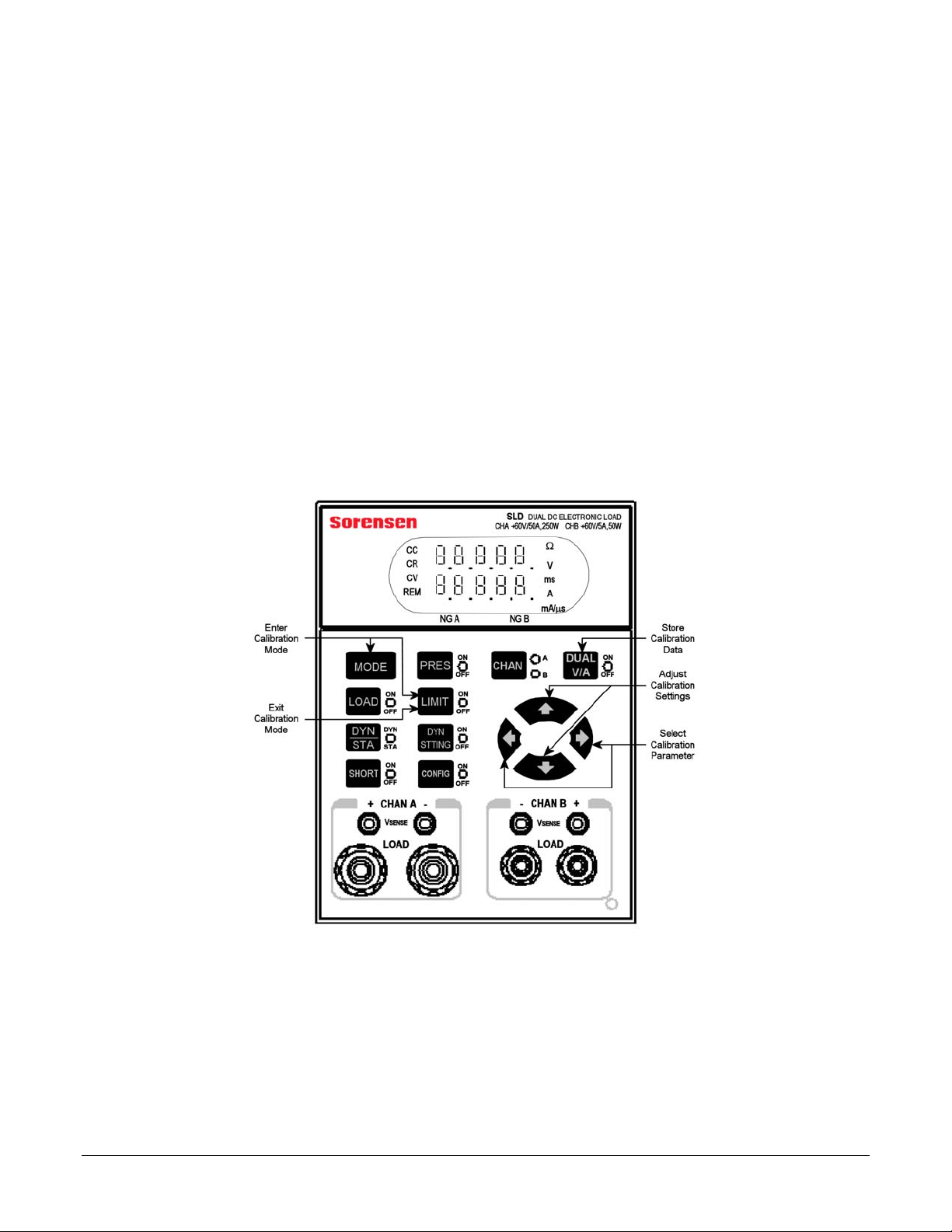
1.1 CALIBRATION MODE
This section provides a brief orientation for how to enter, navigate, adjust and
store settings, and exit the calibration mode.
SECTION 1
Figure 1-1. SLD Series Front Panel
SLD Calibration Manual 1-1
Page 8
Operation Description Elgar Electronics Corporation
1.1.1 NAVIGATION AND SETTING
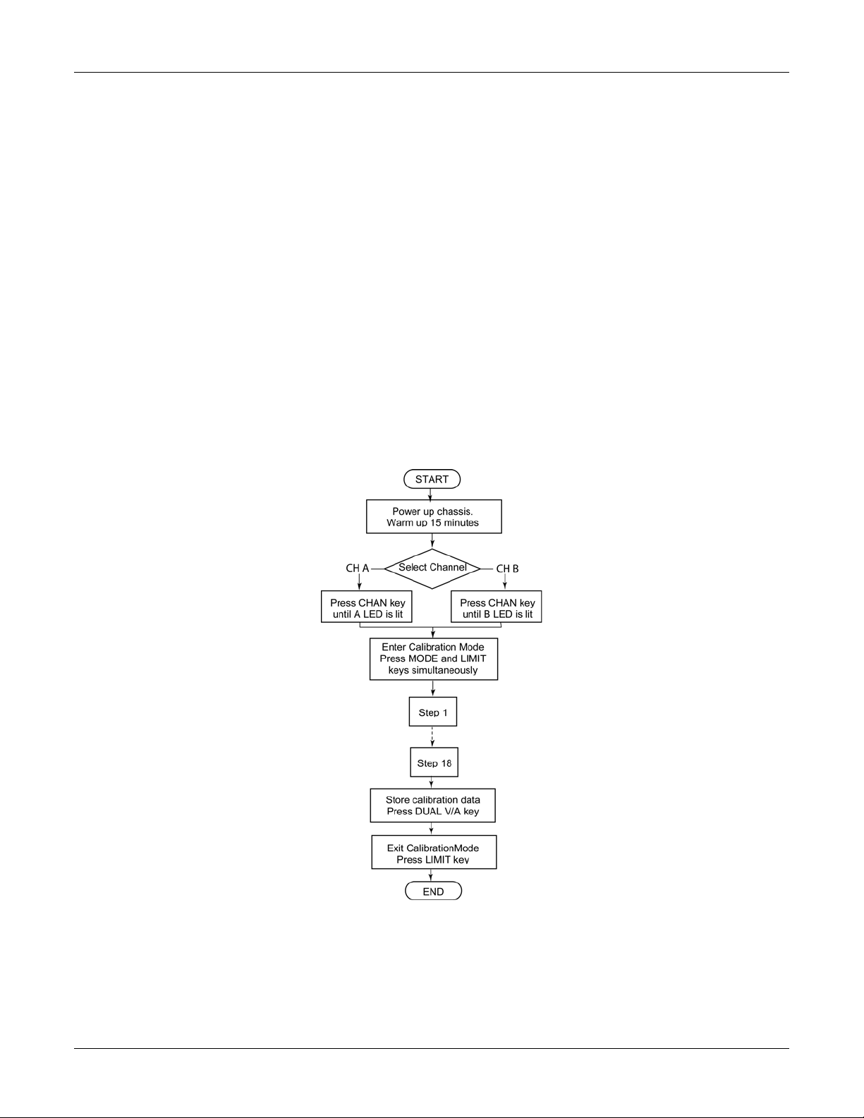
1. Press CHAN key to select channel (A or B) to be calibrated (each
channel is calibrated separately).
2. Press MODE and LIMIT keys simultaneously to enter calibration
mode (Constant Current is default initial mode).
3. Press key to return to previous item (parameter); press to
advance to next item
NOTE: There are 18 items (parameters) to calibrate.
4. Load level and status are set to default value automatically at each
step.
5. Press keys to adjust the calibration values.
6. Press DUAL V/A key to store the calibration data.
7. Press LIMIT key to exit calibration mode.
Refer to
Figure 1-2 for a flowchart of the calibration procedure.
Figure 1-2. SLD Series Calibration Procedure Flowchart
1-2 SLD Calibration Manual
Page 9

CALIBRATION PROCEDURE
2.1 CALIBRATION SETUP
Prior to starting the calibration procedure, gather the necessary equipment
(Section
minutes.
2.1.1 EQUIPMENT REQUIRED
2.1.1), then power up the chassis and allow it to warm up for 15
Voltage/Current Source/Calibrator: Krohn-Hite EDC 521.
Current Shunt: Prodigit 7550.
Digital Multi-meter (DMM): Agilent 34401A.
DC Power Supply: SGA80-125. (Supply may depend upon models
being calibrated. This model covers any module in the SLD
family.)
SECTION 2
Current Probe: Tektronix A6303.
2.2 CHANNEL A CALIBRATION
Press CHAN key to light the A LED.
Press both MODE and LIMIT keys simultaneously to enter calibration mode.
Initial default mode is Constant Current (CC) Mode.
SLD Calibration Manual 2-1
Page 10
Calibration Procedure Elgar Electronics Corporation
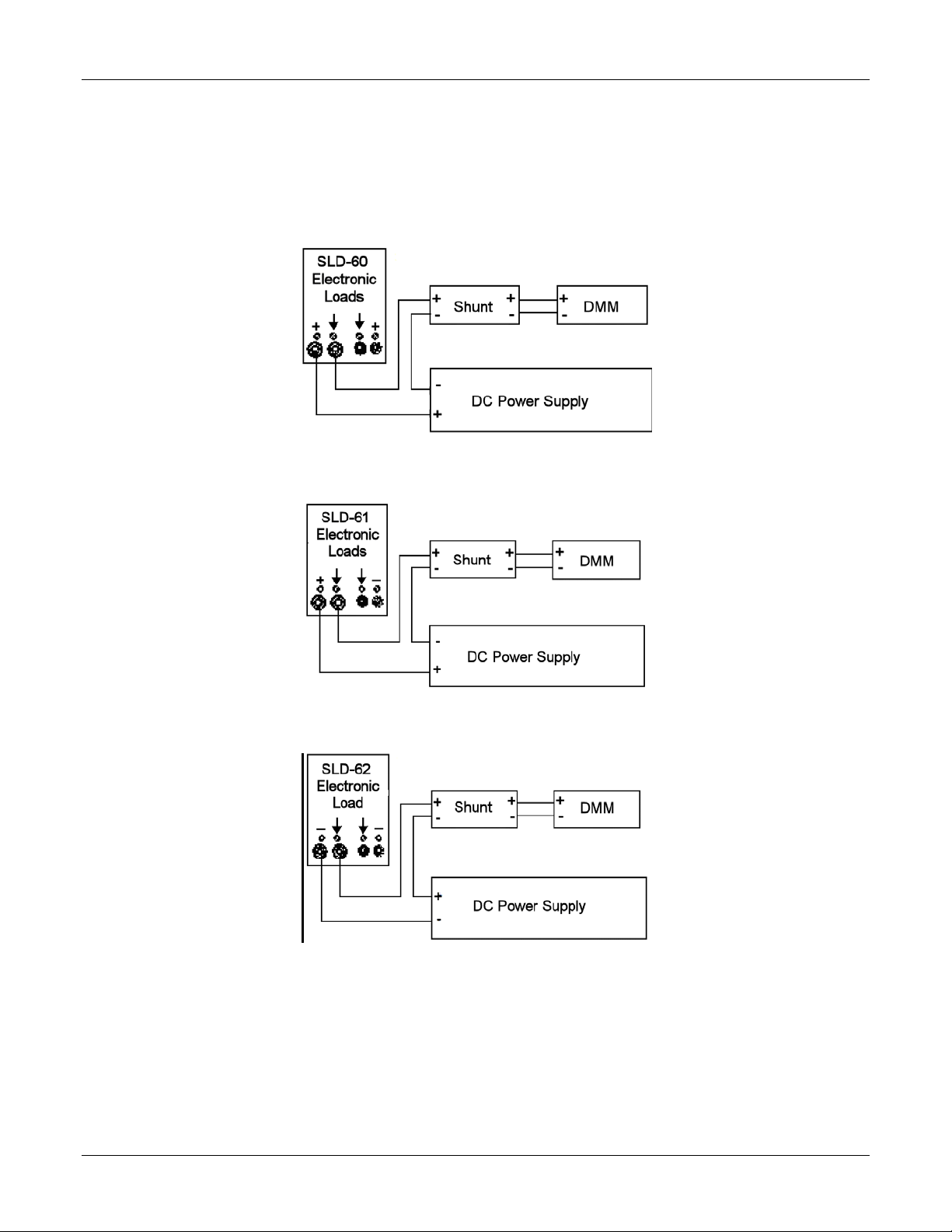
2.2.1 CONSTANT CURRENT (CC) MODE CALIBRATION
Make the appropriate connections per Figure 2-1, Figure 2-2 or Figure 2-3,
for the Load module being calibrated.
N
OTE: Figure 2-1 refers to both SLD-60 and SLD-80.
Figure 2-1. Channel A CC Mode Connections for SLD-60 or SLD-80 Calibration
Figure 2-2. Channel A CC Mode Connections for SLD-61 Calibration
Figure 2-3. Channel A CC Mode Connections for SLD-62 Calibration
2-2 SLD Calibration Manual
Page 11
Elgar Electronics Corporation Calibration Procedure
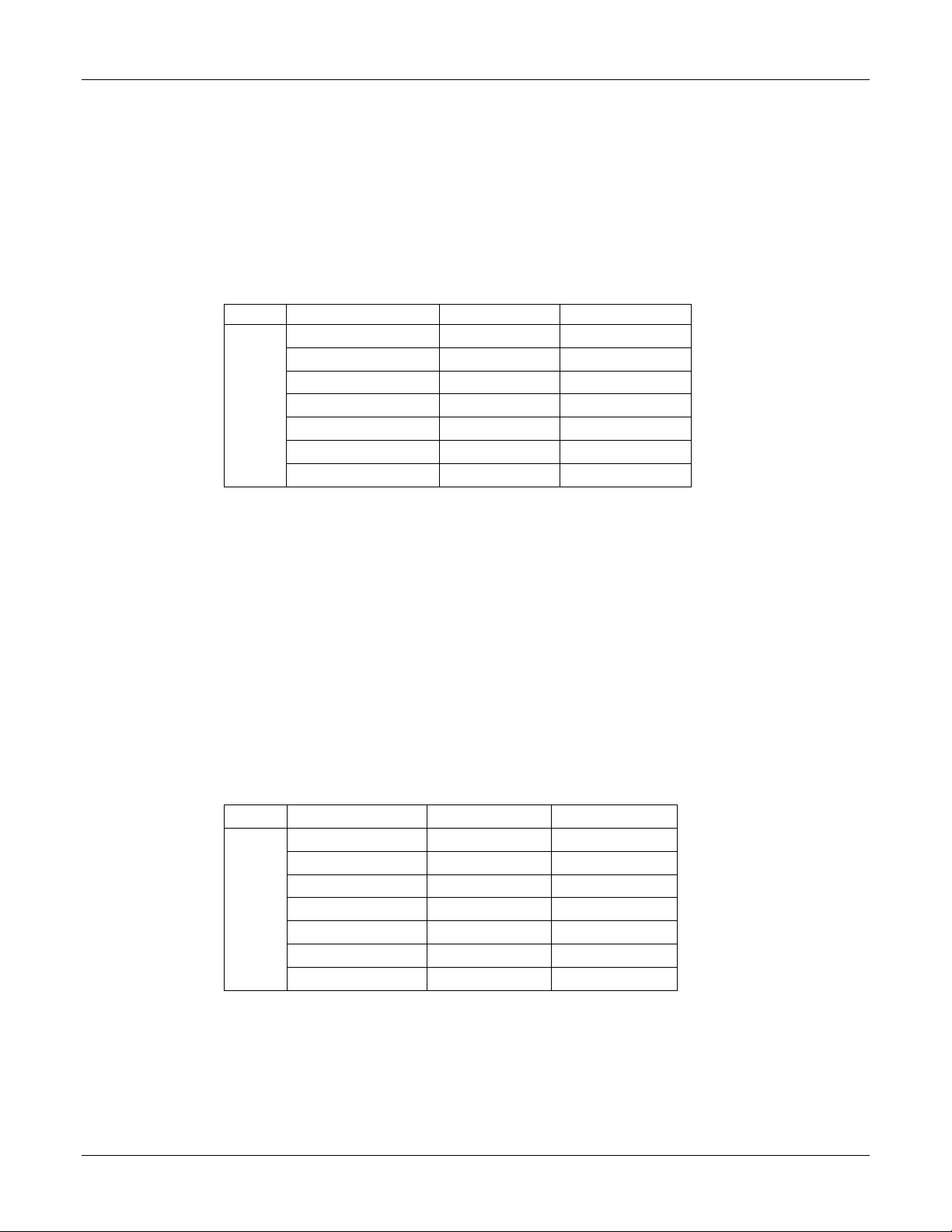
Range I Offset and Gain, Channel A CC Mode
1. Set DC power supply to +5VDC.
2. PRES ON (press PRES key until its LED is lit); set load current setting
to match the value shown in Load Setting column of
model being calibrated.
3. LOAD ON (press LOAD key until its LED is lit); adjust using the
keys until the DMM reading matches the value shown in DMM
Reading column
Table 2-1, for the model being calibrated.
ITEM MODEL Load Setting DMM Reading
SLD-60-505-255 0.000 A 0.000A
SLD-61-505-255 0.000 A 0.000A
SLD-60-20-102 0.0000A 0.0000A
1
SLD-80-20-102 0.0000A 0.0000A
SLD-61-5-752 0.0000A 0.0000A
SLD-62-5-752 0.0000A 0.0000A
SLD-60-105-550 0.0000A 0.0000A
Table 2-1. Channel A CC Mode Range I Offset Calibration Parameters
Table 2-1, for the
4.
Scroll to next calibration parameter, Item 2 (press ).
5. Set DC power supply to +5VDC.
6. PRES ON (press PRES key until its LED is lit); set load current setting
to match the value shown in Load Setting column of
Table 2-2, for the
model being calibrated.
7. LOAD ON (press LOAD key until its LED is lit); adjust using the
keys until the DMM reading matches the value shown in DMM
Reading column of
8. Repeat Steps 1 through 7 (press to return to previous item) until no
Table 2-2, for the model being calibrated.
further adjustments are necessary for the DMM reading to match the
value in the DMM Reading column for both calibration parameters
(Items 1 and 2).
ITEM MODEL Load Setting DMM Reading
SLD-60-505-255 5.000 A 5.000A
SLD-61-505-255 5.000 A 5.000A
SLD-60-20-102 2.002A 2.002A
2
SLD-80-20-102 2.002A 2.002A
SLD-61-5-752 0.5000A 0.5000A
SLD-62-5-752 0.5000A 0.5000A
SLD-60-105-550 10.001A 10.001A
Table 2-2. Channel A CC Mode Range 1 Gain Adjustment Parameters
9.
Scroll to next calibration parameter, Item 3 (press ).
SLD Calibration Manual 2-3
Page 12

Calibration Procedure Elgar Electronics Corporation
Range II Offset and Gain, Channel A CC Mode
1. Set DC power supply to +5VDC.
2. PRES ON (press PRES key until its LED is lit); set load current setting
to match the value shown in Load Setting column of
model being calibrated.
3. LOAD ON (press LOAD key until its LED is lit); adjust using the
keys until the DMM reading matches the value shown in DMM
Reading column of
Table 2-3, for the model being calibrated.
ITEM MODEL Load Setting DMM Reading
SLD-60-505-255 0.000 A 0.000A
SLD-61-505-255 0.000 A 0.000A
SLD-60-20-102 0.000A 0.000A
3
SLD-80-20-102 0.000A 0.000A
SLD-61-5-752 0.000A 0.000A
SLD-62-5-752 0.000A 0.000A
SLD-60-105-550 0.000A 0.000A
Table 2-3. Channel A CC Mode Range II Offset Calibration Parameters
Table 2-3, for the
4. Scroll to next calibration parameter, Item 4 (press ).
5. Set DC power supply to +5VDC at the input terminal.
6. PRES ON (press PRES key until its LED is lit); set load current setting
to match the value shown in Load Setting column of
Table 2-4, for the
model being calibrated.
7. LOAD ON (press LOAD key until its LED is lit); adjust using keys
until the DMM reading matches the value shown in DMM Reading
column of
8. Repeat Steps 1 through 7 (press to return to previous item) until no
Table 2-4, for the model being calibrated.
further adjustments are necessary for the DMM reading to match the
value in the DMM Reading column for both calibration parameters
(Items 3 and 4).
ITEM MODEL Load Setting DMM Reading
SLD-60-505-255 50.00 A 50.00A
SLD-61-505-255 50.00 A 50.00A
SLD-60-20-102 20.00 A 20.00 A
4
SLD-80-20-102 20.00 A 20.00 A
SLD-61-5-752 5.000 A 5.000A
SLD-62-5-752 5.000 A 5.000A
SLD-60-105-550 100.01 A 100.01A
Table 2-4. Channel A CC Mode Range II Gain Adjustment Parameters
9.
Scroll to next calibration parameter, Item 5 (press ).
2-4 SLD Calibration Manual
Page 13

Elgar Electronics Corporation Calibration Procedure
2.2.2 DIGITAL VOLT METER (DVM) CALIBRATION, CHANNEL A
Make the appropriate connections per Figure 2-1, Figure 2-2 or Figure 2-3,
for the Load module being calibrated.
Note:
Figure 2-1 refers to both SLD-60 and SLD-80.
Figure 2-4. Channel A DVM Connections for SLD-60 or SLD-80 Calibration
Figure 2-5. Channel A DVM Connections for SLD-61 Calibration
Figure 2-6. Channel A DVM Connections for SLD-62 Calibration
SLD Calibration Manual 2-5
Page 14

Calibration Procedure Elgar Electronics Corporation
DVM, Channel A
1. Set the DC Voltage Standard to the value shown in DC Input column
of
Table 2-5.
2. Adjust using keys until the DMM reading matches the value in
DMM Reading column.
3. Scroll to next item (press ) and repeat Steps 1 and 2 for each item
through Item 8.
4. Repeat Steps 1 through 3 for all calibration parameters, Items 5
through 8 (press three times to return to Item 5) until no further
adjustments are necessary for the DMM reading to match the value in
the DMM Reading column of
Table 2-5.
ITEM DC INPUT DMM Reading
5
6
7
8
*
0.000 V 0.000 V
15.0000 V 15.000 V
0.000 V 0.000 V
60.000 V 60.00 V
80.000 V 80.00 V
* Applies to SLD-80-20-102 only
Table 2-5. Channel A DVM Calibration Settings
5.
Scroll to next calibration parameter, Item 9 (press ).
2-6 SLD Calibration Manual
Page 15

Elgar Electronics Corporation Calibration Procedure
2.2.3 DIGITAL CURRENT METER (DAM) CALIBRATION, CHANNEL A
Make the appropriate connections per
DAM, Channel A
1. Set the DC power supply to +5VDC to input terminal.
2. Set the load level setting for the load model being calibrated, as
shown in
3. PRES OFF (press PRES key until its LED is not lit), so that the DAM
is in Measurement mode and not in Preset mode.
4. LOAD ON (press LOAD key until its LED is lit); adjust using keys
until the actual current read by the shunts is equal to the DAM
reading.
5. Scroll to next item (press ) and repeat steps 1 through 4 for each
item through Item 12.
6. Press three times to return to Item 9 and repeat Steps 1 through 4
until the DAM readout matches the shunt reading for Items 9 through
12 of
Table 2-6.
Table 2-6.
Load Setting
ITEM
(SLD-60-505-255,
SLD-61-505-255,
SLD-60-105-550)
9
10
11
12
7. Scroll to next calibration parameter, Item 13 (press ).
0.000 A 0.000 A 0.000 A
15.00 A/19.00 A 1.500 A 6.002 A
0.000 A 0.000 A 0.000 A
50.00 A/100.01 A 5.000 A 20.00 A
Table 2-6. Channel A DAM Calibration Settings
Load Setting
(SLD-61-5-752,
SLD-62-5-752)
Load Setting
(SLD-80-20-102,
SLD-60-20-102)
SLD Calibration Manual 2-7
Page 16

Calibration Procedure Elgar Electronics Corporation
2.2.4 CONSTANT VOLTAGE (CV) MODE CALIBRATION, CHANNEL A
1. Connect the load to the DMM and DC power supply per Figure 2-7,
Figure 2-8, or Figure 2-9, for the Load module being calibrated.
Note:
2. Set the power source current limit to 0.1A
3. Set the load to CV mode by pressing the MODE key until CV is lit.
Figure 2-7. Channel A CV Mode Connections for SLD-60 or SLD-80 Calibration
Figure 2-7 refers to both SLD-60 and SLD-80.
Figure 2-8. Channel A CV Mode Connections for SLD-61 Calibration
Figure 2-9. Channel A CV Mode Connections for SLD-62 Calibration
2-8 SLD Calibration Manual
Page 17

Elgar Electronics Corporation Calibration Procedure
1. a) Set the DC Power supply to the value shown in the DC INPUT
column of
Table 2-7;
b) set the electronic preset value to the value shown in the Setting
column of
2. PRES OFF (press PRES key until its LED is not lit), so that the DVM
Table 2-7.
is in Measurement mode and not Preset mode.
3. LOAD ON (press LOAD key until its LED is lit); adjust using the
keys until DMM reading matches the value shown in DMM Reading
column of
4. Scroll to next calibration parameter (press ), Item 14, and repeat CV
Table 2-7.
Steps 1 through 3.
5. Press to return to Item 13, and repeat CV Steps 1 through 4 until
no further adjustments are required for both Items 13-14.
ITEM Setting DC INPUT DMM Reading
13
14
*
0.2000 V 61.00 V / 0.1A 0.2000 V
60.00 V 61.00 V / 0.1A 60.00 V
80.00 V 81.00 V / 0.1A 80.00 V
* Applies to SLD-80-20-102 only
Table 2-7. Channel A CV Mode Calibration Settings
6.
Scroll to next calibration parameter, Item 15 (press ).
SLD Calibration Manual 2-9
Page 18

Calibration Procedure Elgar Electronics Corporation
2.2.5 CONSTANT RESISTANCE (CR) MODE CALIBRATION, CHANNEL A
Make the appropriate connections per Figure 2-10, Figure 2-11, or
Figure 2-11, for the Load module being calibrated.
Note: ** Vsense must be connected with DC INPUT COM.
Set the load to CR mode by pressing the MODE key until the CR is lit.
Figure 2-10. Channel A CR Mode Connections for SLD-60
Figure 2-11. Channel A CR Mode Connections for SLD-61
Figure 2-12. Channel A CR Mode Connections for SLD-62
2-10 SLD Calibration Manual
Page 19

Elgar Electronics Corporation Calibration Procedure
CR Range I Offset and Gain, Channel A CR Mode
1. Set load to match the value in CR Range I Offset column of Table 2-8,
for the model being calibrated.
2. Set the DC Voltage Standard to match the value in IV Sense Input
column of
3. LOAD ON (press LOAD key until its LED is lit).
4. Adjust using keys until DMM reading matches the value in DMM
Reading column of
Table 2-8 for the same model being calibrated.
Table 2-8.
ITEM MODEL
SLD-60-505-255
SLD-61-505-255
SLD-60-20-102
15
SLD-80-20-102
SLD-61-5-752
SLD-62-5-752
SLD-60-105-550
Table 2-8. Channel A CR Mode Range I Offset Calibration Settings
5.
Scroll to next calibration parameter, Item 16 (press ).
6. Set the DC Voltage Standard to match the value in V Sense Input
column of
7. LOAD ON (press LOAD key until its LED is lit). Adjust using keys
until DMM reading matches the value in DMM Reading column of
Table 2-9.
8. Repeat Steps 1 through 7 (press to return to previous item) until no
further adjustments are necessary for the DMM reading to match the
value in the DMM Reading column for both calibration parameters
(Items 15 and 16).
Table 2-9 for the same model being calibrated.
CR Range I OFFSET V SENSE input DMM Reading
4500
4500
11250
15000
45000
45000
2250
Ω
Ω
Ω
Ω
Ω
Ω
Ω
60.00 V 0.013 A
60.00 V 0.013 A
60.00 V 0.0053 A
80.00V 0.0053 A
60.00 V 0.0013 A
60.00 V 0.0013 A
60.00 V 0.026 A
ITEM MODEL
SLD-60-505-255
SLD-61-505-255
SLD-60-20-102
16
SLD-80-20-102
SLD-61-5-752
SLD-62-5-752
SLD-60-105-550
CR Range I GAIN V SENSE input DMM Reading
1.200
1.200
3.000
4.000
12.000
12.000
0.600
Ω
Ω
Ω
Ω
Ω
Ω
Ω
15.00 V 12.50 A
15.00 V 12.50 A
15.00 V 5.000 A
15.00V 3.750 A
30.00 V 2.500 A
30.00 V 2.500 A
6.000 V 10.00 A
Table 2-9. Channel A CR Mode Range I Gain Calibration Setting
SLD Calibration Manual 2-11
Page 20

Calibration Procedure Elgar Electronics Corporation
9. Scroll to next calibration parameter, Item 17 (press ).
CR Range II Offset and Gain, Channel A CR Mode
10. Set load to match the value in CR Range I Offset column of Table 2-10,
for the model being calibrated.
11. Set the DC voltage standard to match the value in V Sense Input
column of
12. LOAD ON (press LOAD key until its LED is lit).
13. Adjust using keys until DMM reading matches the value in DMM
Reading column of
Table 2-10 for the same model being calibrated.
Table 2-10.
ITEM MODEL CR Range II OFFSET V SENSE input
SLD-60-505-255
SLD-61-505-255
SLD-60-20-102
17
SLD-80-20-102
SLD-61-5-752
SLD-62-5-752
SLD-60-105-550
1.200
1.200
3.000
4.000
12.000
12.000
0.600
Ω
Ω
Ω
Ω
Ω
Ω
Ω
15.00 V 12.50 A
15.00 V 12.50 A
15.00 V 5.000 A
15.00 V 3.750 A
30.00 V 2.500 A
30.00 V 2.500 A
6.000 V 10.00 A
Current Reading
(DAM)
Table 2-10. Channel A CR Mode Range II Offset Calibration Settings
14.
Scroll to next calibration parameter, Item 18 (press ).
15. Set the DC voltage standard to match the value in IV Sense Input
column of
16. LOAD ON (press LOAD key until its LED is lit). Adjust using keys
until DMM reading matches the value in DMM Reading column of
Table 2-11.
17. Repeat Steps 1 through 7 (press to return to previous item) until no
further adjustments are necessary for the DMM reading to match the
value in the DMM Reading column for both calibration parameters
(Items 17 and 18).
ITEM MODEL CR Range II GAIN V SENSE input
SLD-60-505-255
SLD-61-505-255
SLD-60-20-102
18
SLD-80-20-102
SLD-61-5-752
SLD-62-5-752
SLD-60-105-550
Table 2-11 for the same model being calibrated.
0.04
0.04
0.100
0.133
0.400
0.400
0.020
Ω
Ω
Ω
Ω
Ω
Ω
Ω
2.000 V 50.00 A
2.000 V 50.00 A
25.000 V 20.00 A
2.660 V 20.00 A
2.000 V 5.000 A
2.000 V 5.000 A
2.000 V 100.00 A
Current Reading
(DAM)
2-12 SLD Calibration Manual
Page 21

Elgar Electronics Corporation Calibration Procedure
Table 2-11. Channel A CR Mode Range II Gain Calibration Settings
2.2.6 STORE CHANNEL A CALIBRATION DATA
Press DUAL V/A key to store the calibration data.
Press LIMIT key to exit the calibration mode.
SLD Calibration Manual 2-13
Page 22

Calibration Procedure Elgar Electronics Corporation
2.3 CHANNEL B CALIBRATION
Press CHAN to light the B LED.
Press both MODE and LIMIT simultaneously to enter calibration mode. Initial
default mode is Constant Current (CC) Mode.
2.3.1 CONSTANT CURRENT (CC) MODE CALIBRATION, CHANNEL B
Make the appropriate connections per Figure 2-13, Figure 2-14 or Figure 2-15
for the load module being calibrated.
Note: refers to both SLD-60 and SLD-80.
Figure 2-13. Channel B CC Mode Connections for SLD-60 Calibration
Figure 2-14. Channel B CC Mode Connections for SLD-61 Calibration
Figure 2-15. Channel B CC Mode Connections for SLD-62 Calibration
2-14 SLD Calibration Manual
Page 23

Elgar Electronics Corporation Calibration Procedure
Range I Offset and Gain, Channel B CC Mode
1. Set DC power supply to +5VDC.
2. PRES ON (press PRES key until its LED is lit); set load current setting
to match the value shown in Load Setting column of
Table 2-12
3. LOAD ON (press LOAD key until its LED is lit); adjust using the
, for the model being calibrated.
keys until the DMM reading matches the value shown in DMM
Reading column of
Table 2-12
ITEM MODEL Load Setting DMM Reading
SLD-60-505-255 0.000 A 0.000A
SLD-61-505-255 0.000 A 0.000A
SLD-60-20-102 0.0000A 0.0000A
1
SLD-80-20-102 0.0000A
0.0000A
SLD-61-5-752 0.0000A 0.0000A
SLD-62-5-752 0.0000A 0.0000A
SLD-60-105-550 0.0000A 0.0000A
Table 2-12. CHANNEL B CC Mode Range I Offset Calibration Parameters
Scroll to next calibration parameter, Item 2 (press ).
4.
5. Set DC power supply to +5VDC.
6. PRES ON (press PRES key until its LED is lit); set load current setting
to match the value shown in Load Setting column of
Table 2-13, for
the model being calibrated.
7. LOAD ON (press LOAD key until its LED is lit); adjust using the
keys until the DMM reading matches the value shown in DMM
Reading column of
8. Repeat Steps 1 through 7 (press to return to previous item) until no
Table 2-13, for the model being calibrated.
further adjustments are necessary for the DMM reading to match the
value in the DMM Reading column for both calibration parameters
(Items 1 and 2).
ITEM MODEL Load Setting DMM Reading
SLD-60-505-255 0.500 A 0.500A
SLD-61-505-255 0.500 A 0.500A
SLD-60-20-102 2.002A 2.002A
2
SLD-80-20-102 2.002A 2.002A
SLD-61-5-752 0.5000A 0.5000A
SLD-62-5-752 0.5000A 0.5000A
SLD-60-105-550 0.5000A 0.5000A
Table 2-13. Channel B CC Mode Range 1 Gain Adjustment Parameters
9. Scroll to next calibration parameter, Item 3 (press ).
SLD Calibration Manual 2-15
Page 24

Calibration Procedure Elgar Electronics Corporation
Range II Offset and Gain, Channel B CC Mode
1. Set DC power supply to +5VDC.
2. PRES ON (press PRES key until its LED is lit); set load current setting
to match the value shown in Load Setting column of
the model being calibrated.
3. LOAD ON (press LOAD key until its LED is lit); adjust using the
keys until the DMM reading matches the value shown in DMM
Reading column of
Table 2-14, for the model being calibrated.
ITEM MODEL Load Setting DMM Reading
SLD-60-505-255 0.00 A 0.000A
SLD-61-505-255 0.00 A 0.000A
SLD-60-20-102 0.000A 0.000A
3
SLD-80-20-102 0.000A 0.000A
SLD-61-5-752 0.000A 0.000A
SLD-62-5-752 0.000A 0.000A
SLD-60-105-550 0.000A 0.000A
Table 2-14, for
Table 2-14. CHANNEL B CC Mode Range II Offset Adjust Pparameters.
Scroll to next calibration parameter, Item 4 (press ).
4.
5. Set DC power supply to +5VDC at the input terminal.
6. PRES ON (press PRES key until its LED is lit); set load current setting
to match the value shown in Load Setting column of
Table 2-15, for
the model being calibrated.
7. LOAD ON (press LOAD key until its LED is lit); adjust using keys
until the DMM reading matches the value shown in DMM Reading
column of
8. Repeat Steps 1 through 7 (press to return to previous item) until no
Table 2-15, for the model being calibrated.
further adjustments are necessary for the DMM reading to match the
value in the DMM Reading column for both calibration parameters
(Items 3 and 4).
ITEM MODEL Load Setting DMM Reading
SLD-60-505-255 5.000 A 5.000A
SLD-61-505-255 5.000 A 5.000A
SLD-60-20-102 20.00 A 20.00A
4
SLD-80-20-102 20.00 A 20.00A
SLD-61-5-752 5.000 A 5.000A
SLD-62-5-752 5.000 A 5.000A
SLD-60-105-550 100.01 A 100.01A
Table 2-15. Channel B CC Mode Range II Gain Adjustment Parameters
9. Scroll to next calibration parameter, Item 5 (press ).
2-16 SLD Calibration Manual
Page 25

Elgar Electronics Corporation Calibration Procedure
2.3.2 DIGITAL VOLT METER (DVM) CALIBRATION, CHANNEL B
Make the appropriate connections per Figure 2-16, Figure 2-17, or
Figure 2-18, for the Load module being calibrated.
Note:
Figure 2-16 refers to both SLD-60 and SLD-80.
Figure 2-16. Channel B DVM Connections for SLD-60 or SLD-80 Calibration
Figure 2-17. Channel B DVM Connections for SLD-61 Calibration
Figure 2-18. Channel B DVM Connections for SLD-62 Calibration
SLD Calibration Manual 2-17
Page 26

Calibration Procedure Elgar Electronics Corporation
DVM, Channel B
1. Set the DC Voltage Standard to the values shown in DC Input column
of
Table 2-16.
2. Adjust using keys until the DMM reading matches the value in
DMM Reading column.
3. Scroll to next item (press ) and repeat Steps 1 and 2 for each item
through Item 8.
4. Repeat Steps 1 through 3 for all calibration parameters, Items 5
through 8 (press three times to return to Item 5) until no further
adjustments are necessary for the DMM reading to match the value in
the DMM Reading column of
Table 2-16.
ITEM DC INPUT DMM Reading
5
6
7
8
*
0.000 V 0.000 V
15.0000 V 15.000 V
0.000 V 0.000 V
60.000 V 60.000 V
80.000 V 80.000 V
* Applies to SLD-80-20-102 only
Table 2-16. Channel B DVM Calibration Settings
5.
Scroll to next calibration parameter, Item 9 (press ).
2-18 SLD Calibration Manual
Page 27

Elgar Electronics Corporation Calibration Procedure
2.3.3 DIGITAL CURRENT METER (DAM) CALIBRATION, CHANNEL B
Make the appropriate connections per
DAM, Channel B
1. Set the DC power supply to +5VDC to input terminal.
2. Set the load level setting for the model being calibrated, as shown in
Setting column of
3. PRESS OFF (press PRES key until its LED is not lit), so that the DAM
is in Measurement mode and not in Preset mode.
4. LOAD ON (press LOAD key until its LED is lit); adjust using keys
until the DMM Reading matches the value in DMM Reading column of
Table 2-17.
5. Scroll to next item (press ) and repeat steps 1 through 4 for each
item through Item 12.
6. Repeat Steps 1 through 5 for all calibration parameters, Items 9
through 12 (press three times to return to Item 9) until no further
adjustments are necessary for the DMM reading to match the value in
the DMM Reading column of
Table 2-17.
Table 2-17.
ITEM Setting DMM Reading
9
10
11
12
Table 2-17. Channel B DAM Calibration Settings
for SLD-60-20-102 and SLD-80-20-102
7.
Scroll to next calibration parameter, Item 13 (press ).
0.0000 A 0.000 A
1.500 A 6.002 A
0.0000 A 0.000 A
5.000 A 20.00 A
SLD Calibration Manual 2-19
Page 28

Calibration Procedure Elgar Electronics Corporation
2.3.4 CONSTANT VOLTAGE (CV) MODE CALIBRATION, CHANNEL B
1. Connect the load to the DMM and DC power supply per Figure 2-19,
Figure 2-20, or Figure 2-21, for the Load module being calibrated.
Note:
2. Set the power source current limit to 0.1A
3. Set the load to CV mode by pressing the MODE key until CV is lit.
Figure 2-19 refers to both SLD-60 and SLD-80.
Figure 2-19. Channel B CV Mode Connections for SLD-60 or SLD-80 Calibration
Figure 2-20. Channel B CV Mode Connections for SLD-61 Calibration
Figure 2-21. Channel B CV Mode Connections for SLD-62 Calibration
2-20 SLD Calibration Manual
Page 29

Elgar Electronics Corporation Calibration Procedure
1. a) Set the DC Power supply to the value shown in the DC INPUT
column of
Table 2-18;
b) set the electronic preset value to the value shown in the Setting
column of
2. PRES OFF (press PRES key until its LED is not lit), so that the DVM
Table 2-18.
is in Measurement mode and not Preset mode.
3. LOAD ON (press LOAD key until its LED is lit); adjust using the
keys until DMM reading matches the value shown in DMM Reading
column of
4. Scroll to next calibration parameter (press ), Item 14, and repeat CV
Table 2-18.
Steps 1 through 3.
5. Press to return to Item 13, and repeat CV Steps 1 through 4 until
no further adjustments are required for both Items 13-14.
ITEM Setting DC INPUT DVM
13
14
*
0.200 V 61.00 V / 0.1A 0.2000 V
60.00 V 61.00 V / 0.1A 60.00 V
80.00 V 81.00 V / 0.1A 80.00 V
* Applies to SLD-80-20-102 only
Table 2-18. Channel B CV Mode Calibration Settings
6.
Scroll to next calibration parameter, Item 15 (press ).
SLD Calibration Manual 2-21
Page 30

Calibration Procedure Elgar Electronics Corporation
2.3.5 CONSTANT RESISTANCE (CR) MODE CALIBRATION, CHANNEL B
Make the appropriate connections per Figure 2-22, Figure 2-23, or
Figure 2-24, for the Load module being calibrated.
Note: ** Vsense must be connected with DC INPUT COM.
Set the load to CR mode by pressing the MODE key until the CR is lit.
Figure 2-22. Channel B CR Mode Connections for SLD-60
Figure 2-23. Channel B CR Mode Connections for SLD-61
Figure 2-24. Channel B CR Mode Connections for SLD-62
2-22 SLD Calibration Manual
Page 31

Elgar Electronics Corporation Calibration Procedure
CR Range I Offset and Gain, Channel B CR Mode
1. Set load to match the value in CR Range I Offset column of
Table 2-19, for the model being calibrated.
2. Set the DC Voltage Standard to match the value in V Sense Input
column of
3. LOAD ON (press LOAD key until its LED is lit).
4. Adjust using keys until DMM reading matches the value in DMM
Reading column of
Table 2-19 for the same model being calibrated.
Table 2-19.
ITEM
15
Table 2-19. Channel B CR Range I Offset Calibration Settings
5.
Scroll to next calibration parameter, Item 16 (press ).
6. Set the DC Voltage Standard to match the value in IV Sense Input
column of
7. LOAD ON (press LOAD key until its LED is lit). Adjust using keys
MODEL CR Range I OFFSET V SENSE input DMM Reading
SLD-60-505-255
SLD-61-505-255
SLD-60-20-102
SLD-80-20-102
SLD-61-5-752
SLD-62-5-752
SLD-60-105-550 45000
4500
Ω
4500
Ω
11250 Ω
15000
45000
45000
Ω
Ω
Ω
Ω
60.00 V 0.013 A
60.00 V 0.013 A
60.00 V 0.0053 A
80.00V 0.0053 A
60.00 V 0.0013 A
60.00 V 0.0013 A
60.00 V
0.0013 A
Table 2-20 for the same model being calibrated.
until DMM reading matches the value in DMM Reading column of
Table 2-20.
8. Repeat Steps 1 through 7 (press to return to previous item) until no
further adjustments are necessary for the DMM reading to match the
value in the DMM Reading column for both calibration parameters
(Items 15 and 16).
ITEM MODEL
SLD-60-505-255 1.200 Ω 60.00 V
SLD-61-505-255 1.200 Ω 60.00 V
SLD-60-20-102 3.000 Ω 15.00 V
SLD-80-20-102 4.000 Ω 15.00V
16
SLD-61-5-752 12.000 Ω 60.00 V
SLD-62-5-752
SLD-60-105-550
Table 2-20. Channel B CR Mode Range I Gain Calibration Setting
9.
Scroll to next calibration parameter, Item 17 (press ).
SLD Calibration Manual 2-23
CR Range I GAIN V SENSE input
12.000
12.000
Ω
Ω
60.00 V 5.00 A
60.00 V 5.00 A
DMM Reading
5.00 A
5.00 A
5.000 A
3.750 A
5.00 A
Page 32

Calibration Procedure Elgar Electronics Corporation
CR Range II Offset and Gain, Channel A CR Mode
1. Set load to match the value in CR Range I Offset column of
Table 2-21, for the model being calibrated.
2. Set the DC voltage standard to match the value in IV Sense Input
column of
3. LOAD ON (press LOAD key until its LED is lit).
4. Adjust using keys until DMM reading matches the value in DMM
Reading column of
Table 2-21 for the same model being calibrated.
Table 2-21.
ITEM MODEL CR Range II OFFSET V SENSE input DMM Reading
SLD-60-505-255
SLD-61-505-255
SLD-60-20-102
17
SLD-80-20-102
SLD-61-5-752
SLD-62-5-752
SLD-60-105-550
12.00
12.00
3.000
4.000
12.000
12.000
12.000
Ω
Ω
Ω
Ω
Ω
Ω
Ω
60.00 V 5.00 A
60.00 V 5.00 A
15.00 V 5.00 A
15.00V 3.750 A
60.00 V 5.000 A
60.00 V 5.000 A
60.00 V 5.000 A
Table 2-21. Channel B CR Mode Range II Offset Calibration Settings
5.
Scroll to next calibration parameter, Item 18 (press ).
6. Set the DC voltage standard to match the value in V Sense Input
column of
7. LOAD ON (press LOAD key until its LED is lit). Adjust using keys
until DMM reading matches the value in DMM Reading column of
Table 2-22.
8. Repeat Steps 1 through 7 (press to return to previous item) until no
further adjustments are necessary for the DMM reading to match the
value in the DMM Reading column for both calibration parameters
(Items 17 and 18).
ITEM MODEL CR Range II GAIN V SENSE input DMM Reading
SLD-60-505-255
SLD-61-505-255
SLD-60-20-102
18
SLD-80-20-102
SLD-61-5-752
SLD-62-5-752
SLD-60-105-550
Table 2-22 for the same model being calibrated.
2.000
2.000
0.500
0.133
2.000
2.000
2.000
Ω
Ω
Ω
Ω
Ω
Ω
Ω
5.000 V 2.500 A
5.000 V 2.500 A
5.000 V 10.00 A
2.66 V 20.00 A
5.000 V 2.500 A
5.000 V 2.500 A
5.000 V 2.500 A
Table 2-22. Channel B CR Mode Range II Gain Calibration Settings
2-24 SLD Calibration Manual
Page 33

Elgar Electronics Corporation Calibration Procedure
2.3.6 STORE CHANNEL B CALIBRATION DATA
Press DUAL V/A key to store the calibration data.
Press LIMIT key to exit the calibration mode.
SLD Calibration Manual 2-25
Page 34

Calibration Procedure Elgar Electronics Corporation
2.4 CALIBRATION DATA RECORD
SLD SERIES ELECTRONIC LOAD Calibration Data Record
MODEL No: ____________________ Serial No: _______________________
DATE: ________________________ Inspector: _______________________
Item Description CHAN A CHAN B
1 CC Range I Offset
2 CC Range I Gain
3 CC Range II Offset
4 CC Range II Gain
5 DVM Range I Offset
6 DVM Range I Gain
7 DVM Range II Offset
8 DVM Range II Gain
9 DAM Range I Offset
10 DAM Range I Gain
11 DAM Range II Offset
12 DAM Range II Gain
13 CV Offset
14 CV Gain
15 CR. Range I Offset
16 CR Range I Gain
17 CR Range II Offset
18 CR Range II Gain
2-26 SLD Calibration Manual
 Loading...