

Page 1

SGI Series DC
Power Supplies
Operation Manual
M550221-01 Rev AA www.programmablepower.com
Page 2

Page 3

About AMETEK
AMETEK Programmable Power, Inc., a unit of AMETEK Electronic Instruments Group (a division
of AMETEK, Inc.), is a global leader in the design and manufacture of precision, programmable
power supplies for R&D, test and measurement, process control, power bus simulation and
power conditioning applications across diverse industrial segments. Offering bench-top supplies
to rack-mounted industrial power subsystems, AMETEK Programmable Power is the proud
manufacturer of Elgar, Sorensen, California Instruments, Power Ten, and Amrel brand power
supplies and electronic loads.
AMETEK, Inc. is a leading global manufacturer of electronic instruments and electromechanical
devices with annualized sales of $3.6 billion. The company has over 14,000 colleagues working
at more than 120 manufacturing facilities and more than 80 sales and service centers in the
United States and around the world.
Trademarks
AMETEK is a registered trademark of AMETEK, Inc.
Other trademarks, registered trademarks, and product names are the property of their respective
owners and are used herein for identification purposes only.
Notice of Copyright
SGI Series DC Power Supplies Operation Manual © 2014, AMETEK Programmable Power, Inc.,
All rights reserved.
Exclusion for Documentation
UNLESS SPECIFICALLY AGREED TO IN WRITING, AMETEK PROGRAMMABLE POWER,
INC. (“AMETEK”)
(a) MAKES NO WARRANTY AS TO THE ACCURACY, SUFFICIENCY OR SUITABILITY OF
ANY TECHNICAL OR OTHER INFORMATION PROVIDED IN ITS MANUALS OR OTHER
DOCUMENTATION.
(b) ASSUMES NO RESPONSIBILITY OR LIABILITY FOR LOSSES, DAMAGES, COSTS OR
EXPENSES, WHETHER SPECIAL, DIRECT, INDIRECT, CONSEQUENTIAL OR INCIDENTAL,
WHICH MIGHT ARISE OUT OF THE USE OF SUCH INFORMATION. THE USE OF ANY SUCH
INFORMATION WILL BE ENTIRELY AT THE USER’S RISK, AND
(c) REMINDS YOU THAT IF THIS MANUAL IS IN ANY LANGUAGE OTHER THAN ENGLISH,
ALTHOUGH STEPS HAVE BEEN TAKEN TO MAINTAIN THE ACCURACY OF THE
TRANSLATION, THE ACCURACY CANNOT BE GUARANTEED. APPROVED AMETEK
CONTENT IS CONTAINED WITH THE ENGLISH LANGUAGE VERSION, WHICH IS POSTED
AT WWW.PROGRAMMABLEPOWER.COM.
Date and Revision
March 2015, Rev AA
Part Number
M550221-01
Contact Information
Telephone: 800 733 5427 (toll free in North America)
858 450 0085 (direct)
Fax: 858 458 0267
Email: sales.ppd@ametek.com
service.ppd@ametek.com
Web: www.programmablepower.com
M550221-01 Rev AA iii
Page 4

Product Family: SGI Series DC Power Supplies
Warranty Period: Five Years
Warranty Terms
AMETEK Programmable Power, Inc. (“AMETEK”) provides this written warranty covering the
Product stated above, and if the Buyer discovers and notifies AMETEK in writing of any defect in
material or workmanship within the applicable warranty period stated above, then AMETEK may,
at its option: repair or replace the Product; or issue a credit note for the defective Product; or
provide the Buyer with replacement parts for the Product.
The Buyer will, at its expense, return the defective Product or parts thereof to AMETEK in
accordance with the return procedure specified below. AMETEK will, at its expense, deliver the
repaired or replaced Product or parts to the Buyer. Any warranty of AMETEK will not apply if the
Buyer is in default under the Purchase Order Agreement or where the Product or any part
thereof:
is damaged by misuse, accident, negligence or failure to maintain the same as
specified or required by AMETEK;
is damaged by modifications, alterations or attachments thereto which are not
authorized by AMETEK;
is installed or operated contrary to the instructions of AMETEK;
is opened, modified or disassembled in any way without AMETEK’s consent; or
is used in combination with items, articles or materials not authorized by AMETEK.
The Buyer may not assert any claim that the Products are not in conformity with any warranty
until the Buyer has made all payments to AMETEK provided for in the Purchase Order
Agreement.
Product Return Procedure
1. Request a Return Material Authorization (RMA) number from the repair facility (must be
done in the country in which it was purchased):
In the USA, contact the AMETEK Repair Department prior to the return of the product
to AMETEK for repair:
Telephone: 800-733-5427, ext. 2295 or ext. 2463 (toll free North America)
858-450-0085, ext. 2295 or ext. 2463 (direct)
Outside the USA, contact the nearest Authorized Service Center (ASC). A full listing
can be found either through your local distributor or our website,
www.programmablepower.com, by clicking Support and going to the Service Centers
tab.
2. When requesting an RMA, have the following information ready:
Model number
Serial number
Description of the problem
Note:
Unauthorized returns will not be accepted and will be returned at the shipper’s expense.
Note:
A returned product found upon inspection by AMETEK, to be in specification is subject to
an evaluation fee and applicable freight charges.
M550221-01 Rev AA iv
Page 5
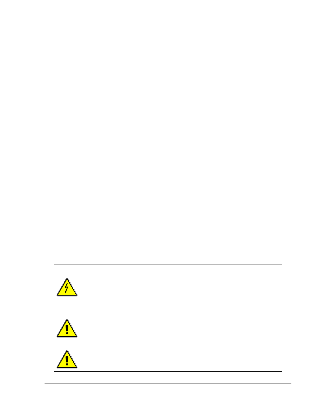
WARNING!
Hazardous voltages might be present when covers are removed. Qualified
personnel must use extreme caution when servicing this equipment. Circuitry,
test points, and output voltages might be floating with respect to chassis
ground. Do not touch electrical circuits, and use appropriately rated test
equipment. A safety ground wire must be connected from the chassis to the
AC mains input when servicing this equipment.
WARNING!
This equipment contains ESD sensitive input/output connection ports. When
installing equipment, follow ESD safety procedures. Electrostatic discharges
might cause damage to the equipment.
IMPORTANT SAFETY INSTRUCTIONS
Before applying power to the system, verify that your product is configured properly for
your particular application.
Only qualified personnel, who understand and deal with attendant hazards in power
supplies, are allowed to perform installation and servicing.
Ensure that the AC mains input ground is connected properly to the chassis safety
ground connection. Similarly, other power ground lines, including those to application
and maintenance equipment, must be grounded properly for both personnel and
equipment safety. Always ensure that facility AC mains input is de-energized prior to
connecting or disconnecting any cable.
In normal operation from the front panel, the operator does not have access to
hazardous voltages within the chassis. However, depending on the application
configuration, HIGH VOLTAGES HAZARDOUS TO HUMAN SAFETY might be
normally generated on the output terminals. The user must ensure that the output power
lines are labeled properly as to the safety hazards and that any possibility for inadvertent
contact with hazardous voltages is eliminated.
Guard against risks of electrical shock during open cover checks by not touching any
portion of the electrical circuits. Even when power is off, capacitors may retain an
electrical charge. Use safety glasses during open cover checks to avoid personal injury
by any sudden component failure.
Neither AMETEK Programmable Power Inc., San Diego, California, USA, oor any of the
subsidiary sales organizations, can accept any responsibility for personnel, material or
inconsequential injury, loss or damage that results from improper use of the equipment
and accessories.
M550221-01 Rev AA v
Page 6
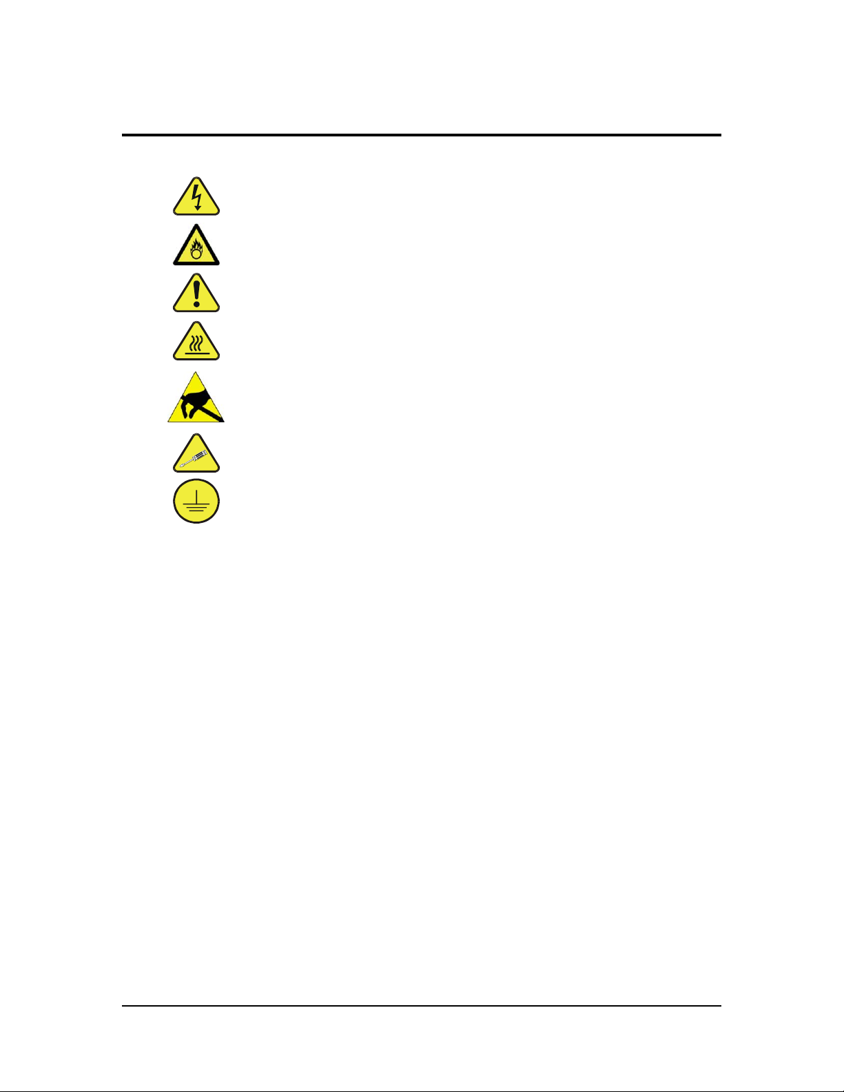
SAFETY SYMBOLS
WARNING: Electrical Shock Hazard
HAZARD: Strong oxidizer
GENERAL WARNING/CAUTION: Read the accompanying message for
specific information.
BURN HAZARD: Hot Surface Warning. Allow to cool before servicing.
DO NOT TOUCH: Touching some parts of the instrument without
protection or proper tools could result in damage to the part(s) and/or
the instrument.
TECHNICIAN SYMBOL: All operations marked with this symbol are to
be performed by qualified maintenance personnel only.
ELECTRICAL GROUND: This symbol inside the instrument marks the
central safety grounding point for the instrument.
M550221-01 Rev AA vi
Page 7

FCC NOTICE
This equipment has been tested and found to comply with the limits for a Class A digital
device, pursuant to part 15 of the FCC Rules. These limits are designed to provide
reasonable protection against harmful interference when the equipment is operated in a
commercial environment.
This equipment generates, uses, and can radiate radio frequency energy and, if not
installed and used in accordance with the instruction manual, may cause harmful
interference to radio communications. Operation of this equipment in a residential area
is likely to cause harmful interference in which case the user will be required to correct
the interference at his own expense.
M550221-01 Rev AA vii
Page 8

ABOUT THIS MANUAL AND REGULATORY COMPLIANCE
This manual has been written for the Sorensen SGI Series of power supplies, which
have been designed and certified to meet the Low Voltage and Electromagnetic
Compatibility Directive Requirements of the European Community.
These models have been designed and tested to meet the Electromagnetic
Compatibility directive (European Council directive 2004/108/EC; generally referred to
as the EMC directive) and to the requirements of the Low Voltage directive (European
Council directive 2006/95/EC, 93/68/EEC, dated 22 July 1993). In addition these
models have been found compliant with FCC 47 CFR Part 15, Subpart B107(e)
Class A, 109(g) Class A.
Since the Low Voltage Directive is to ensure the safety of the equipment operator,
universal graphic symbols have been used both on the unit itself and in this manual to
warn the operator of potentially hazardous situations (see Safety Instruction page).
viii M550221-01 Rev AA
Page 9

CONTENTS
SECTION 1 OVERVIEW .......................................... 1-1
1.1 General Description ..................................................................................... 1-1
1.2 Specifications ............................................................................................... 1-3
1.2.1 Environmental Characteristics ........................................................................ 1-3
1.2.2 Electrical Characteristics ................................................................................ 1-3
1.2.3 SGI Series Voltage and Current Specifications .............................................. 1-7
1.2.4 Physical Characteristics ................................................................................. 1-8
SECTION 2 INSTALLATION ................................... 2-1
2.1 Inspection ..................................................................................................... 2-1
2.2 Contents of Shipment .................................................................................. 2-1
2.3 Location and Mounting ................................................................................ 2-2
2.3.1 Rack Mounting ................................................................................................ 2-3
2.3.2 K550212-01 ASSEMBLY STEPS (OPTION KIT) ........................................... 2-4
2.3.3 K550213-01 ASSEMBLY STEPS (OPTION KIT) ........................................... 2-6
2.3.4 Chassis Removal from Rack .......................................................................... 2-7
2.4 Input/Output Connections ........................................................................... 2-8
2.5 Wire Selection ............................................................................................ 2-11
2.5.1 Wire Size ......................................................................................................2-11
2.6 LOAD CONSIDERATIONS .......................................................................... 2-14
2.6.1 Inductive and Stored-Energy Loads .............................................................2-14
2.7 Outline Drawings ........................................................................................ 2-15
SECTION 3 OPERATION ......................................... 3-1
3.1 Introduction .................................................................................................. 3-1
3.1.1 Front/Rear Panels........................................................................................... 3-1
M550221-01 Rev AA ix
Page 10

Contents Sorensen SGI Series
3.2 Basic Operation and Output Verification .................................................... 3-9
3.2.1 Initial Setup ..................................................................................................... 3-9
3.2.2 Default Programming Menu ............................................................................ 3-9
3.2.3 Constant-Voltage Mode Operation ...............................................................3-10
3.2.4 Constant-Current Mode Operation ...............................................................3-11
3.2.5 Overvoltage Protection .................................................................................3-12
3.3 Initial Start-Up Displays ............................................................................. 3-13
3.4 Display Elements ........................................................................................ 3-14
3.5 Navigation ................................................................................................... 3-15
3.6 Editing ......................................................................................................... 3-16
3.6.1 Aborting an Edit ............................................................................................3-17
3.7 Menu Map.................................................................................................... 3-18
3.7.1 Home Menu ..................................................................................................3-18
3.7.2 Default Programming Menu ..........................................................................3-18
3.7.3 Navigating from Home Menu Page 1 ...........................................................3-18
3.7.4 Navigating from Home Menu Page 2 ...........................................................3-19
3.7.5 Navigating from Home Menu Page 3 ...........................................................3-19
3.7.6 Sequence Menu............................................................................................3-20
3.7.7 Sequence Programming Operation ..............................................................3-20
3.7.8 Constant-Power Setup Menu .......................................................................3-21
3.7.9 Remote Menu ...............................................................................................3-21
3.7.10 Remote Control Screen Examples ...............................................................3-22
3.7.11 Warning Screens ..........................................................................................3-22
3.7.12 Other Screens ...............................................................................................3-22
3.8 Programming/Operating Functions .......................................................... 3-22
3.8.1 Voltage, Current, and Overvoltage Protection Programming .......................3-22
3.8.2 Save ..............................................................................................................3-23
3.8.3 Recall ............................................................................................................3-24
3.8.4 Sequencing ...................................................................................................3-25
3.8.5 Constant-Power Mode ..................................................................................3-34
3.8.6 Home Timeout ..............................................................................................3-35
3.8.7 Display Brightness ........................................................................................3-35
3.8.8 Lock Key .......................................................................................................3-35
3.8.9 Language ......................................................................................................3-35
3.8.10 Info ................................................................................................................3-36
3.8.11 Remote .........................................................................................................3-36
3.8.12 System ..........................................................................................................3-39
3.8.13 Warning Screens ..........................................................................................3-40
x M550221-01 Rev AA
Page 11

Sorensen SGI Series Contents
3.9 Remote Analog Control Connector (J1).................................................... 3-40
3.10 Remote Current Programming .................................................................. 3-45
3.10.1 Remote Current Programming by Resistance ..............................................3-45
3.10.2 Remote Current Programming by Voltage Source .......................................3-46
3.11 Remote Voltage Programming .................................................................. 3-47
3.11.1 Remote Voltage Programming by Resistance .............................................3-47
3.11.2 Remote Voltage Programming by Voltage Source .......................................3-48
3.12 Remote Overvoltage Programming ........................................................... 3-49
3.13 Remote Output On/Off Control .................................................................. 3-50
3.13.1 Remote Output ON/OFF by Contact Closure ...............................................3-50
3.13.2 Remote Output ON/OFF Control by External Source ..................................3-50
3.13.3 Remote Shutdown(S/D) ................................................................................3-51
3.14 Remote Sensing ......................................................................................... 3-52
3.15 Floating and Polarized Output ................................................................... 3-55
3.16 Parallel and Series Operation .................................................................... 3-56
3.16.1 Parallel Operation .........................................................................................3-56
3.16.2 Series Operation ...........................................................................................3-58
SECTION 4 CALIBRATION AND VERIFICATION.. 4-60
4.1 Introduction ................................................................................................ 4-60
4.1.1 Calibration and Verification Cycle .................................................................4-60
4.1.2 Preparation ...................................................................................................4-60
4.2 Calibration and Verification Procedures................................................... 4-61
4.2.1 Constant-Current Mode ................................................................................4-62
4.2.2 Constant-Voltage Mode ................................................................................4-62
4.2.3 Resistive-Control Programming Current Sources ........................................4-63
4.2.4 Change Calibration Date ..............................................................................4-64
4.3 Remote Isolated Analog Interface (Option) Calibration and Verification
Procedures ........................................................................................................... 4-64
4.3.1 Constant-Current Mode ................................................................................4-64
4.3.2 Constant-Voltage Mode ................................................................................4-65
4.3.3 Change Calibration Date ..............................................................................4-66
SECTION 5 MAINTENANCE ................................... 5-1
5.1 Introduction .................................................................................................. 5-1
5.2 Preventive Maintenance ............................................................................... 5-1
5.3 Fuses ............................................................................................................. 5-3
M550221-01 Rev AA xi
Page 12

Contents Sorensen SGI Series
LIST OF TABLES
Table 2–1. Maximum AC Current Ratings, PFC Models ............................................. 2-9
Table 2–2. Maximum AC Current Ratings, Non-PFC Models ....................................... 2-9
Table 2–3. Input/Output Connectors ........................................................................... 2-9
Table 2–4. Input Terminal Connections ..................................................................... 2-10
Table 2–5. Output Terminal Connections .................................................................. 2-10
Table 2–6. Recommended Lugs ............................................................................... 2-10
Table 2–7. Recommended Sense Connector Tools .................................................. 2-10
Table 2–8. Minimum Wire Size ................................................................................. 2-11
Table 2–9. Wire Resistance and Voltage Drop, 20°C ................................................ 2-13
Table 3–1. Front Panel Controls and Indicators .......................................................... 3-2
Table 3–2. Rear Panel Connectors and Controls, Standard ........................................ 3-6
Table 3–3. Rear Panel Connectors and Controls, GPIB Option .................................. 3-7
Table 3–4. Rear Panel Connectors and Controls, Ethernet Option ............................. 3-8
Table 3–5. Analog Control Connector (J1), Designations and Functions ................... 3-44
Table 5–1. Fuse Ratings ............................................................................................. 5-3
xii M550221-01 Rev AA
Page 13

Sorensen SGI Series Contents
LIST OF FIGURES
Figure 1-1. Model Number Decoding .......................................................................... 1-2
Figure 2-1. Rack Mount Assembly for 3U Models ........................................................ 2-4
Figure 2-2. Rack Mount Assembly for 6U Models ................................ ....................... 2-6
Figure 2-3. Diode Connection ................................................................................... 2-14
Figure 2-4. Installation Drawing, 3U Models 10V-30V ............................................... 2-16
Figure 2-5. Installation Drawing, 3U Models 40V-600V ................................ ............ 2-17
Figure 2-6. Installation Drawing, 3U Models 800V and 1000V ................................. 2-18
Figure 2-7. Installation Drawing, 6U Models 20kW-30kW ......................................... 2-19
Figure 2-8. Rear Panel, Standard, 3U Models 10V-30V ............................................ 2-20
Figure 2-9. Rear Panel, GPIB Option, 3U Models 10V-30V ...................................... 2-21
Figure 2-10. Rear Panel, Ethernet Option, 3U Models 10V-30V................................ 2-22
Figure 2-11. Rear Panel, Standard, 3U Models 40V-600V ........................................ 2-23
Figure 2-12. Rear Panel, GPIB Option, 3U Models 40V-600V .................................. 2-24
Figure 2-13. Rear Panel, Ethernet Option, 3U Models 800V and 1000V ................... 2-25
Figure 2-14. Rear Panel, Standard, 6U Models 20kW-30 kW ................................... 2-26
Figure 2-15. Rear Panel, GPIB Option, 6U Models 20kW-30 kW .............................. 2-27
Figure 2-16. Rear Panel, Ethernet Option, 6U Models 20kW-30 kW ......................... 2-28
Figure 2-17. Instructions for Assembly of AC and DC Covers ................................... 2-29
Figure 3-1. Front Panel Controls and Indicators (3U Model Shown) ............................ 3-1
Figure 3-2. Rear Panel Interface, Standard, 3U Models 10V-30V ............................... 3-3
Figure 3-3. Rear Panel Interface, GPIB Option, 3U Models 10V-30V .......................... 3-3
Figure 3-4. Rear Panel Interface, Ethernet Option, 3U Models 10V-30V ..................... 3-3
Figure 3-5. Rear Panel Interface, Standard, 3U Models 40V-600V ............................. 3-4
Figure 3-6. Rear Panel Interface, GPIB Option, 3U Models 40V-600V ........................ 3-4
Figure 3-7. Rear Panel Interface, Ethernet Option, 3U Models 800V and 1000V ........ 3-4
Figure 3-8. Rear Panel Interface, Standard, 6U Models 20kW-30kW .......................... 3-5
Figure 3-9. Rear Panel Interface, GPIB Option, 6U Models 20kW-30kW .................... 3-5
Figure 3-10. Rear Panel Interface, Ethernet Option, 6U Models 20kW-30kW ............. 3-5
Figure 3-11. Burn-in Sequence Example .................................................................. 3-31
Figure 3-12. Constant-Power Example ..................................................................... 3-34
Figure 3-13. Analog Control Connector (J1) Pin-Out ................................................. 3-41
Figure 3-14. Remote Current Programming Using Resistance .................................. 3-45
Figure 3-15. Remote Current Programming Using 0-5 VDC or 0-10 VDC Source ..... 3-46
Figure 3-16. Remote Voltage Programming Using Resistance ................................. 3-47
Figure 3-17. Remote Voltage Programming Using 0-5 VDC or 0-10 VDC Source ..... 3-48
Figure 3-18. Remote Overvoltage Programming Using DC Voltage Source .............. 3-49
Figure 3-19. Remote Output On/Off Control by Contact Closure ............................... 3-50
Figure 3-20. Remote Output On/Off Using Isolated AC or DC Source ...................... 3-50
Figure 3-21. Remote Output On/Off Using Isolated TTL/CMOS Source .................... 3-51
Figure 3-22. Remote Shutdown Using DC Voltage Source ....................................... 3-51
M550221-01 Rev AA xiii
Page 14

Contents Sorensen SGI Series
Figure 3-23. Remote Voltage Sensing Network ......................................................... 3-52
Figure 3-24. Remote Sense Connection at the Load, 10V-800V Models ................... 3-53
Figure 3-25. Remote Sense Connection at the Load, 1000V Model .......................... 3-54
Figure 3-26. Parallel Connection and Remote Sense ................................................ 3-57
Figure 3-27. Series Connection with Anti-Parallel Diodes ................................ ......... 3-59
Figure 4-1. Potentiometer Locations ......................................................................... 4-67
xiv M550221-01 Rev AA
Page 15

1.1 General Description
The Sorensen SGI Series are general purpose power supplies designed
specifically for laboratory test and systems applications requiring
programmable DC sources with good performance characteristics, such as
accuracy, regulation, and ripple/noise. These power supplies are constantcurrent/constant-voltage supplies with an automatic crossover feature.
SECTION 1
OVERVIEW
A variety of user interfaces are available, ranging from manual front panel control
and standard non–isolated remote analog control, to optional GPIB or isolated
remote analog control.
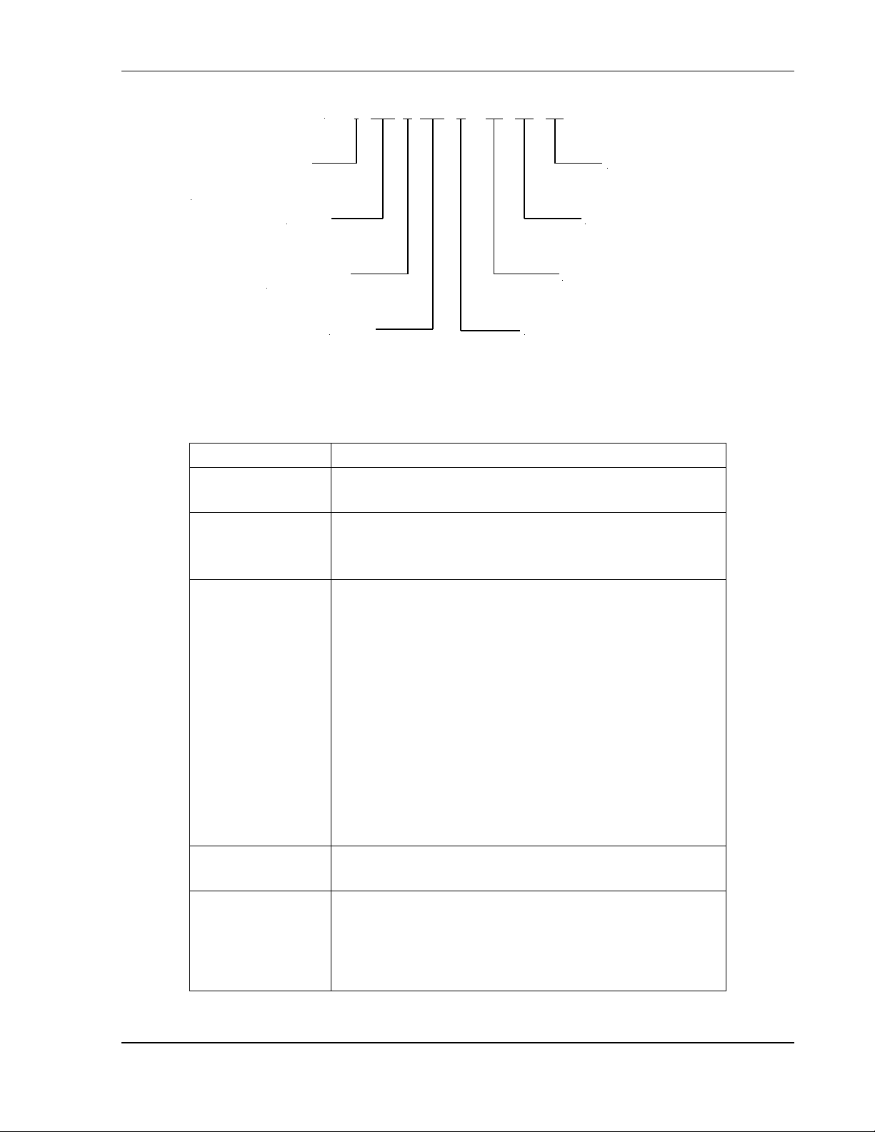
Refer to Figure 1-1 for decoding of the SG Series model number.
M550221-01 Rev AA 1-1
Page 16
Overview Sorensen SGI Series
Option
Description
Control Options
A: Analog
I: Intelligent
Input Options
C: Input Voltage 208/230 VAC, 3-Phase
D: Input Voltage 380/400 VAC, 3-Phase
E: Input Voltage 440/480 VAC, 3-Phase
Remote Control
Options
0A: No Option
1A: IEEE-488.2 + RS-232C
1C: Ethernet + RS-232C
1D: Isolated Analog Interface
1E: Shaft Locks
2A: Combined Options 1A + 1D
2C: Combined Options 1A + 1E (SGA Only)
2G: Combined Options 1C + 1D
2H: Combined Options 1C + 1E (SGA Only)
2J: Combined Options 1D + 1E (SGA Only)
3C: Combined Options 1A + 1D + 1E (SGA Only)
3G: Combined Options 1C + 1D + 1E (SGA Only)
Process Options
AA: No option
AB: Certificate of Calibration (includes test data)
Modifications
AJ: Front panel dust filter (3U models only)
CV: 400Hz AC input at 208 VAC for 6U units only; does not
carry CE, CSA or UL certification; (standard in 3U models)
PF: Passive power factor correction to 0.9 for 40V to 800V
models; (standard in 10V-30V, 50V, and 1000V models)
SG I 100 X 100 C - 1A AA AJ
Control Designation
A = Analog
I = Intelligent
Voltage
4-15 kW = "X"
20-30 kW = "/"
Current
Modifications
Process Options
Remote Control Options
Input Voltage Options
For units up to 999 V/999 A, voltage and current are represented in numeric format, e.g., “100”
represents 100 V. For units at 1000 V/1000 A and above, the voltage and current are
represented by the format “xKx”, e.g., “1K0” represents 1000 V.
Figure 1-1. Model Number Decoding
1-2 M550221-01 Rev AA
Page 17
Sorensen SGI Series Overview
Parameter
Specification
Ambient Temperature
Operating
0 to 50C
Storage
-25 to 65C
Cooling
Forced convection with internal, linearly-variable-speed fans; vents on
front, sides and rear; units may be stacked without clearance above or
below.
Humidity
95% maximum, non-condensing, 0 to 50C; 45C maximum wet-bulb
temperature.
Altitude
5,000 ft (1,524 m) operating at full rated output power, derate 10% of
full power for every 1,000 ft (3,048 m) higher; non-operating to 40,000 ft
(12,192m)
Agency Approvals
CE Compliant: Certified to UL/CSA 61010 and IEC/EN 61010-1 by a
NRTL; LVD Categories: Installation Category II, Pollution Degree 2,
Class II Equipment, for Indoor Use Only;
EMC Directive, EN 61326:1998;
Semi-F47 Compliant
Parameter
Specification
Input Power
Voltage
208/230 VAC ±10%, allowed range 187-253 VAC;
380/400 VAC ±10%, allowed range 342-440 VAC;
440/480 VAC ±10%, allowed range 396-528 VAC
Frequency
47 Hz to 63 Hz; 400 Hz at 208 VAC for 3U models; 400 Hz at
208 VAC for 6U models is an optional modification (“CV” in
model number) and does not carry CE, UL or CSA markings
Configuration
3–phase, 3–wire plus ground; not phase rotation sensitive;
neutral not used.
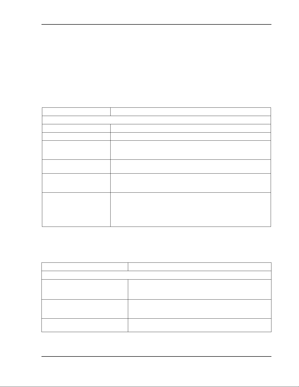
1.2 Specifications
The following subsections provide environmental, electrical, and physical
characteristics for the SGI Series power supplies.
Note:
Note:
Specifications are subject to change without notice.
The SGI Series power supplies are intended for indoor use only. Refer
to Section 2.3 for use/location requirements.
1.2.1 Environmental Characteristics
1.2.2 Electrical Characteristics
Note:
where the remote sense leads are connected.
M550221-01 Rev AA 1-3
Output voltage accuracy, regulation, and stability specifications are valid at the point
Page 18
Overview Sorensen SGI Series
Parameter
Specification
Power Factor (at full rated load; 50/60Hz); contact factory for power factor of specific models
PFC models: 10V-30V, 50V,
1000V, and models with optional
modification, “PF”
0.90, typical, for all AC input ratings; with passive power factor
correction (PFC)
Non-PFC models: 40V-800V
0.75, typical, for 208/230 VAC input;
0.72, typical, for 380/400 VAC input;
0.69, typical, for 440/480 VAC input;
power factor is not solely determined by power supply input
characteristics, but is dependent on the level of DC output power
and interaction with the source impedance of AC mains.
Efficiency
87%, typical, at full load, nominal AC line
Hold-Up Time
1/2 cycle, typical, for loss of all three phases (6.4 ms, typical for
800V/1000V models); 3 cycle, typical, for loss of one phase;
sustained missing phase will result in shutdown of the output.
Rated Output Power
4-15 kW for 3U chassis for10V-30V models;
5-15 kW for 3U chassis for 40V-1000V models;
20-30 kW for 6U chassis for 60V-600V models;
maximum output power is the product of the rated output voltage
and current; for specific values refer to Section 1.2.3.
Load Regulation (specified for ±100% rated load change, at nominal AC input voltage)
Voltage
±0.05%, maximum, of rated output voltage for 10V- 30V models;
±0.02%, maximum, of rated output voltage for 40V-1000V
models
Current
±0.1%, maximum, of rated output current
Line Regulation (specified for ±10% change of nominal AC line voltage, at constant load)
Voltage
±0.05%, maximum, of rated output voltage for 10V-30V models;
±0.01%, maximum, of rated output voltage for 40V-1000V
models
Current
±0.05%, maximum, of rated output current
Temperature Coefficient
Voltage
±0.02%/C, typical, of rated output voltage
Current
±0.03%/C, typical, of rated output current
Stability
±0.05%, typical, of rated output voltage or current, over 8 hrs at
fixed line, load, and temperature, after 30 min warm-up
Output Voltage Ripple/Noise
Refer to Ripple/Noise specifications in tables of Section 1.2.3.
Load Transient Response
1 ms, typical, to recover within 0.75% of rated output voltage for
load step change of 50% of rated output current
Output Voltage Rise Time
(with rated load, resistive; current rise
time same)
10 ms, maximum, from 10-90% of programming change from
zero to rated output voltage for 10V-30V models;
100 ms, maximum, from 5-95% of programming change from
zero to rated output voltage for 40V-1000V models;
contact factory for values of specific models
1-4 M550221-01 Rev AA
Page 19
Sorensen SGI Series Overview
Parameter
Specification
Output Voltage Fall Time
(with rated load, resistive; current fall
time same)
10 ms, maximum, from 90-10% of programming change from
rated output voltage to zero for 10V-30V models;
contact factory for values of specific models
Output Voltage Fall Time
(with no load)
50 ms, maximum, from 90-10% of programming change from
rated output voltage to zero for 10V-30V models;
1.5 s, typical, from 100% to 10% of programming change from
rated output voltage to zero for 40V-1000V models;
contact factory for values of specific models
Front Panel Meter
Display Resolution
4 digit
Voltage Accuracy
(to actual output)
±(0.15% of rated output voltage + 0.1% of actual output + 1 digit)
for 10V-30V models;
±(0.1%, maximum, of rated output voltage + 1 digit) for
40V-1000V models
Current Accuracy
(to actual output)
±(0.4%, maximum, of rated output voltage + 1 digit)
Front Panel Programming
Voltage
±(0.1% of rated output voltage + 0.1% of actual output voltage)
for 10V-30V models;
±0.1%, maximum, of rated output voltage for 40V-1000V models
Current
±(0.4% of rated output current + 0.1% of actual output current)
for 10V-30V models;
±0.4%, maximum, of rated output current for 40V-1000V models
Overvoltage Protection (OVP)
±1%, maximum, of rated output voltage
Remote Sensing
Connection
Voltage accuracy/regulation specifications apply at the point
where the remote sense leads are connected.
Line Drop
1 V, maximum per line for 10V-20V models;
1.5 V, maximum per line for 30V model;
5%, maximum of rated output voltage per line for models, 40V to
less than 160V;
2%, maximum of rated output voltage per line for models greater
than or equal to 160V;
greater level of line drop is allowed, but output voltage regulation
specifications no longer apply.
Line Drop Effect on Output
Voltage
Rated output voltage applies at the rear panel output terminals,
and line drop voltage subtracts from the voltage available at the
load terminals
Remote Analog Interface
Programming Accuracy
Voltage
±0.25%, maximum, of rated output voltage for 0-5 VDC range,
and ±0.5%, maximum, for 0-10 VDC range
Current
±1.0%, maximum, of rated output current for 0-5 VDC range,
and ±1.2%, maximum, for 0-10 VDC range for 10V-30V models;
M550221-01 Rev AA 1-5
Page 20
Overview Sorensen SGI Series
Parameter
Specification
±0.8%, maximum, of rated output current for 0-5 VDC range,
and ±1.0%, maximum, for 0-10 VDC range for 40V-1000V
models
Overvoltage Protection (OVP)
±1%, maximum, of rated output voltage
Readback Monitor Accuracy
Voltage
(of actual output value)
±0.5%, maximum, of rated output voltage
Current
(of actual output value)
±1%, maximum, of rated output current
Resistive-Control Programming
Voltage
0–5 k for 0-100% of rated output voltage
Current
0–5 k for 0-100% of rated output current
Voltage-Control Programming
Voltage
0–5 VDC or 0–10 VDC for 0-100% of rated output voltage
Current
0–5 VDC or 0–10 VDC for 0-100% of rated output current
Overvoltage Protection (OVP)
0.25–5.5 VDC for 5-110% or rated output voltage
Remote Control/Monitor Interface
On/Off control via contact closure, 6-120 VDC or 12-240 VAC,
and TTL or CMOS gate; output voltage and current monitors;
output voltage, current, and OVP programming; summary fault
status
Output Isolation
Output Float Voltage
Negative Output Terminal
±300 V(PK), maximum, with respect to chassis ground;
exceeding the limit will be detected as a fault by a protective
supervisory monitor and shutdown of the output will be
executed; this condition will be latched, requiring reset to
resume normal operation.
Isolation of optional Isolated
Analog Interface (J1) to output
negative terminal
1000 V(PK), maximum; Isolated Analog Interface (J1 signals)
are galvanically isolated from negative output terminal; operation
of Isolated Analog Interface signals should be at SELV safety
voltage conditions to chassis ground.
Reference of standard NonIsolated Analog Interface (J1) to
output negative terminal
The standard Non-Isolated Analog Interface (J1 signals) is
connected to the negative output terminal and, therefore, is not
isolated from the output.
Parallel Operation
Parallel Group
Up to 5 units, of the same voltage rating, may be connected in
parallel for additional output current; specifications apply as for
single unit, with the exception that each additional paralleled unit
will add 0.3% to the output current accuracy. Contact factory for
applications requiring paralleling more than five units.
Series Operation
Series Group
Up to 2 units, of the same current rating, may be connected in
series for additional output voltage; see restrictions in Output
Isolation section.
1-6 M550221-01 Rev AA
Page 21
Sorensen SGI Series Overview
Rated
Voltage,
VDC
Rated Current, ADC
Ripple/
Noise**
RMS,
mV
Ripple/
Noise*
PK–PK,
mV
4 kW
5 kW
8 kW
10 kW
12 kW
15 kW
0-10††
0-400
N/A
0-800
N/A
0-1200
N/A
20
50
0-15††
0-267
N/A
0-534
N/A
0-801
N/A
20
50
0-20††
N/A
0-250
N/A
0-500
N/A
0-750
20
60
0-30††
N/A
0-167
N/A
0-334
N/A
0-501
20
60
Rated
Voltage,
VDC
Rated Current, ADC
Ripple/
Noise**
RMS,
mV
Ripple/
Noise*
PK–PK,
mV
5 kW
10 kW
15 kW
20 kW
25 kW
30 kW
0-40
0-125
0-250
0-375
0-500†
0-625†
0-750†
20
75
0-50
0-100
0-200
0-300
0-400†
0-500†
0-600†
20
75
0-60
0-83
0-167
0-250
0-333
0-417
0-500
20
75
0-80
0-63
0-125
0-188
0-250
0-313
0-375
20
100
0-100
0-50
0-100
0-150
0-200
0-250
0-300
20
100
0-160
0-31
0-63
0-94
0-125
0-156
0-188
25
150
0-200
0-25
0-50
0-75
0-100
0-125
0-150
25
175
0-250
0-20
0-40
0-60
0-80
0-100
0-120
30
200
0-300
0-17
0-33
0-50
0-67
0-83
0-100
30
200
0-330
0-15
0-30
0-45
0-61
0-76
0-91
30
200
0-400
0-12
0-25
0-38
0-50
0-63A
0-75
30
300
0-500
0-10
0-20
0-30
0-40
0-50
0-60
50
350
0-600
0-8
0-17
0-25
0-33
0-42
0-50
60
350
0-800
0-6.2
0-12.5
0-18.7
0-25†
0-31.2†
0-37.5†
80
500
0-1000
0-5
0-10
0-15
0-20†
0-25†
0-30†
100
650
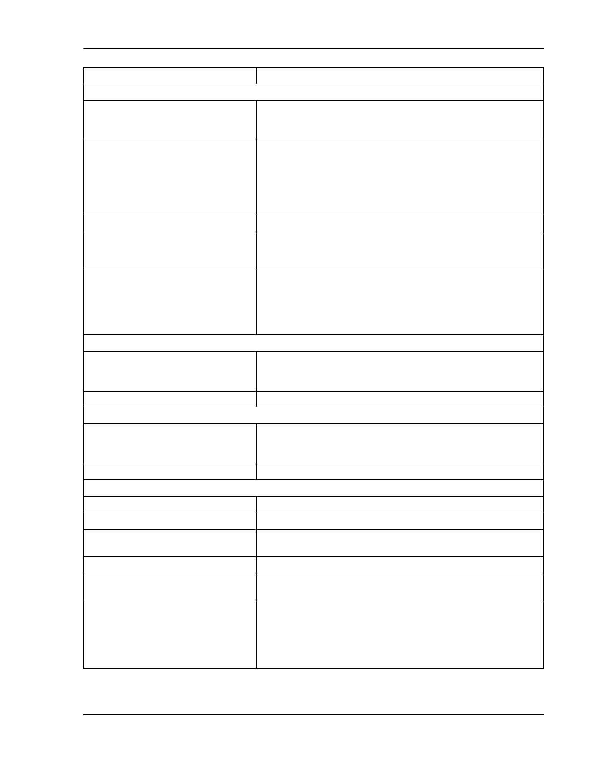
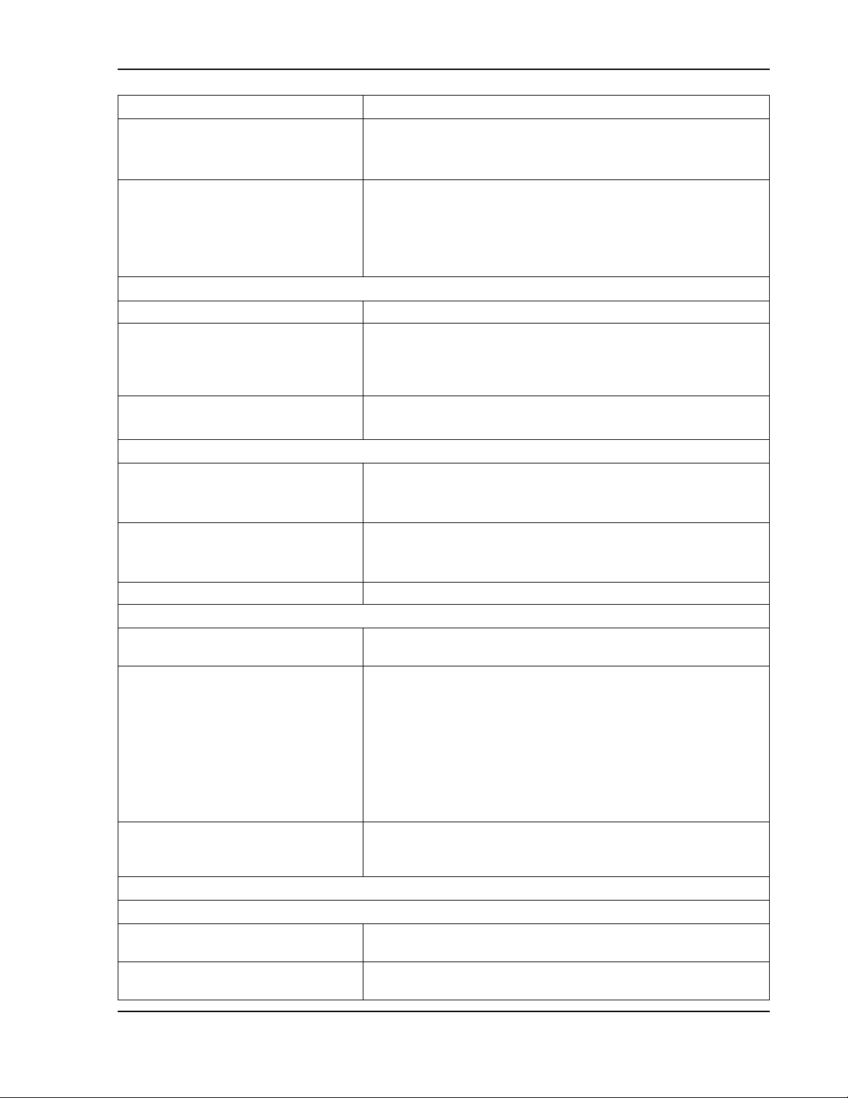
1.2.3 SGI Series Voltage and Current Specifications
The following tables present the specifications for rated voltage and current, and ripple/noise for
the 10V-1000V models.
* PK-PK ripple/noise, over 20 Hz to 20 MHz bandwidth, is measured across a 1 µF capacitor at
the end of a 6’ load cable with the supply operating at full load and nominal AC line voltage.
** RMS ripple/noise, over 20 Hz to 300 kHz bandwidth, is measured directly across the output
terminals with the supply operating at full load and nominal AC input line voltage.
†
Power level not available in 6U models, but could be produced with paralleled 3U units; up to
75 kW could be produced by paralleling up to five units. Paralleling will increase ripple/noise.
††
Models from 10V-30V are not available in 6U chassis.
M550221-01 Rev AA 1-7
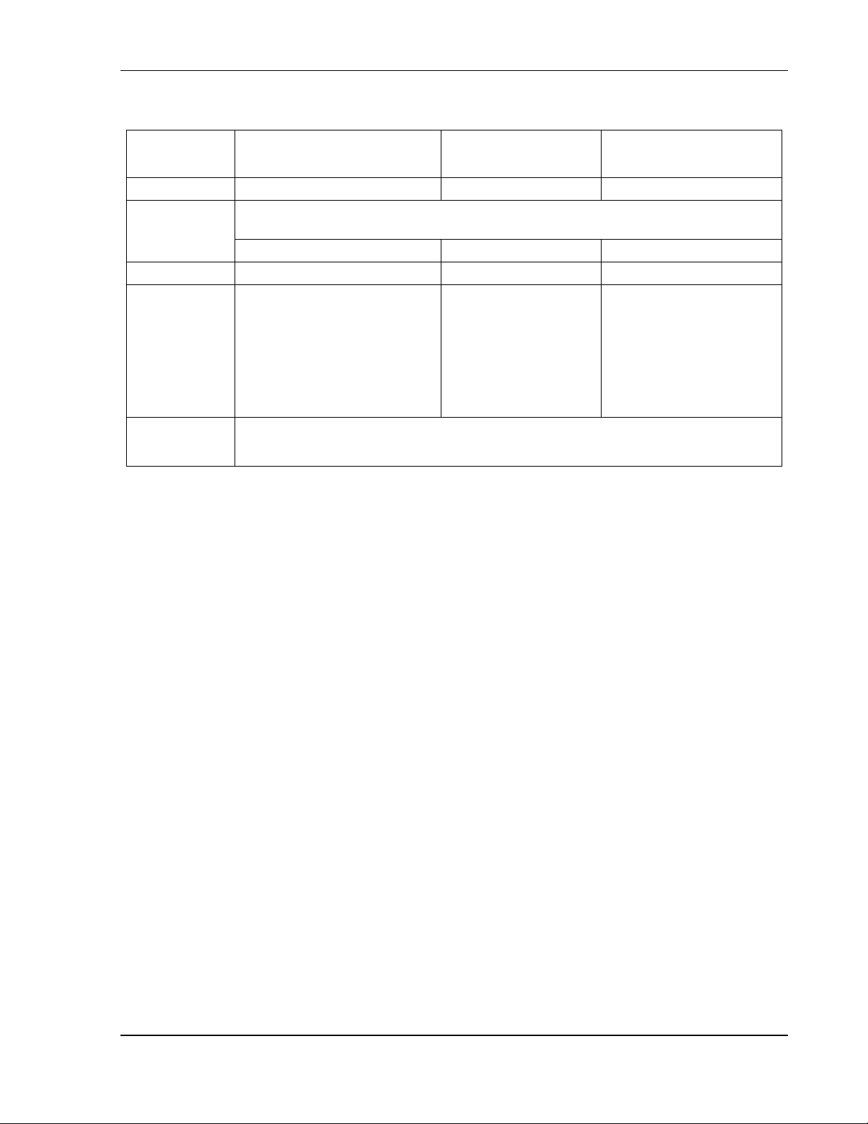
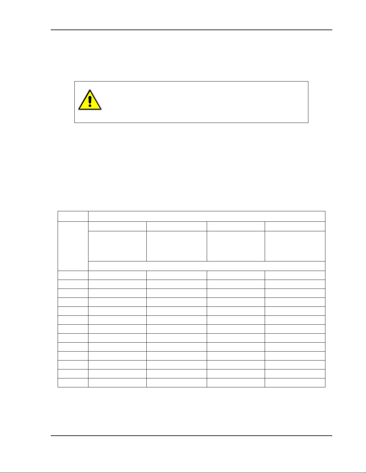
Page 22
Overview Sorensen SGI Series
Dimensions
3U Models,
10V-30V
3U Models,
40V-1000V
6U Models,
60V-600V
Width
19.00 in (48.26 cm)
19.00 in (48.26 cm)
19.00 in (48.26 cm)
Depth
From inner surface of front panel to maximum protrusion of protective covers at rear
panel; refer to installation drawings for chassis dimensions.
28.09 in (71.35 cm)
25.46 in (64.67 cm)
27.18 in (69.04 cm)
Height
5.25 in (13.34 cm)
5.25 in (13.34 cm)
10.5 in (26.67 cm)
Weight
(nominal)
≤ 65 lb (29 kg), (4 kW, 10V, 15V)
≤ 65 lb (29 kg), (5 kW, 20V, 30V)
≤ 85 lb (39 kg), (8 kW, 10V, 15V)
≤ 85 lb (39 kg), (10 kW, 20V, 30V)
≤ 110 lb (50 kg), (12 kW, 10V, 15V)
≤ 110 lb (50 kg), (15 kW, 20V, 30V)
≤ 60 lb (27 kg), (5 kW)
≤ 75 lb (34 kg), (10 kW)
≤ 90 lb (41 kg), (15 kW)
≤ 140 lb (63 kg), (20 KW)
≤ 155 lb (70 kg), (25 kW)
≤ 170 lb (77 kg), (30 kW)
Shipping
Weight
Contact factory for weights of specific models
1.2.4 Physical Characteristics
1-8 M550221-01 Rev AA
Page 23

2.1 Inspection
Inspect the shipping carton for possible damage before unpacking the unit.
Carefully unpack the equipment. Save all packing materials until inspection is
complete. Verify that all items listed on the packing slips have been received.
Visually inspect all exterior surfaces for broken knobs, connectors, or meters.
Inspect for dented or damaged exterior surfaces. External damage may be an
indication of internal damage. If any damage is evident, immediately contact
the carrier that delivered the unit and submit a damage report. Failure to do so
could invalidate future claims. Direct repair issues to Customer Service at 858458-0223 (local) or 1-800-733-5427 (toll free in North America).
SECTION 2
INSTALLATION
2.2 Contents of Shipment
Depending on the model, configuration, and options available for your SGI
Series power supply, the ship kit may include additional parts and accessories.
Minimum items included in the ship kit:
AMETEK manuals CD-ROM (P/N M550008-01) containing the SGI Series
DC Power Supplies Operation Manual (this manual, P/N M550221-01),
and the SG manual for the digital interface options, IEEE 488.2/RS232
and Ethernet Programming Manual (P/N M550129-03).
1. Sense mating connector:
10V-800V models, (Molex P/N 39-01-4031) with loose contacts (Molex P/N 3900-0182)
1000V model, (Molex P/N 39-01-4041) with loose contacts (Molex P/N 39-01-
0182)
2. J1 mating connector (Cinch P/N DB25P or equivalent) normally shipped attached
to rear panel J1
3. Backshell for J1 (DB25) mating connector (Cinch P/N DCH-B-001 or equivalent)
M550221-01 Rev AA 2-1
Page 24
Installation Sorensen SGI Series
WARNING!
This unit is intended for installation in a protected environment. Exposure to
conductive contaminants or corrosive compounds/gases that could be
ingested into the chassis could result in internal damage. To reduce the risk
of fire or electrical shock, install the SGI Series unit in a temperature and
humidity controlled indoor area.
CAUTION!
The unit should be provided with proper ventilation. The rear and both sides
of the unit should be free of obstructions. To ensure proper airflow, a
minimum 4" clearance from the rear air outlet is required. The unit should
not be installed in an ambient temperature greater than 50°C.
CAUTION!
No user serviceable parts inside; service to be performed by qualified
personnel only.
4. Hardware for input/output terminal power connections:
3U, 4-15 kW, 10V-30V models: 1/2-13UNC-2B x 1.25" long, 4 ea, with
nut, washer, and lockwasher;
3U, 5-15 kW, 40V-600V models: 3/8-16UNC-2B x 1.0”, 2 ea, with nut,
washer, and lockwasher;
3U, 5-15 kW, 800V and 1000V models have studs, 1/4-20UNC-2B,
2 ea, with nut, washer, and lockwasher installed on rear panel;
6U, 20-30 kW: 3/8-16UNC-2B x 0.875", 2 ea, with nut and lockwasher,
for DC output; 1/4-20UNC-2B, 4 ea, with Keps nut for AC input.
5. Front panel rack fastener, black screw:
3U, 10V -1000V models: 10-32UNC-2B x 0.5”, 4 ea;
6U, 20-30 kW: 10-32UNC-2B x 0.5”, 8 ea.
Note:
0223 (local) or 1-800-733-5427 (toll free).
Optional accessories:
890-453-03: Paralleling Cable (for up to 5 units, requires one cable per unit
placed in parallel)
K550212-01: 3U Rack Slides (for 4 kW to 15 kW models)
K550213-01: 6U Rack Slides (for 20 kW to 30 kW models)
5550568-01: Front panel dust filter - field installation kit - 3U models only
5551082-01: Optional AC input cover kit - 3U models only
If any of these parts are missing, contact Customer Service at 858458-
2.3 Location and Mounting
Refer to Sections 2.7 for dimensional and installation drawings.
2-2 M550221-01 Rev AA
Page 25

Sorensen SGI Series Installation
2.3.1 Rack Mounting
The SGI Series models are designed for mounting in a standard 19-inch
equipment rack compliant to EIA-310. If additional instrumentation is mounted
in the rack, no additional clearance is required above or below the SGA Series
units.
Support the SGI Series unit using appropriate L-brackets or rack mount slides;
suggested slides kits are listed as follows:
Rack Mount Slide Kit (Option):
3U models, 4–15 kW: AMETEK part number K550212-01
6U models, 20–30 kW: AMETEK part number K550213-01
M550221-01 Rev AA 2-3
Page 26
Installation Sorensen SGI Series
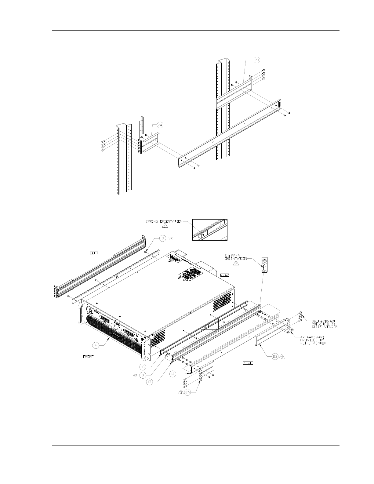
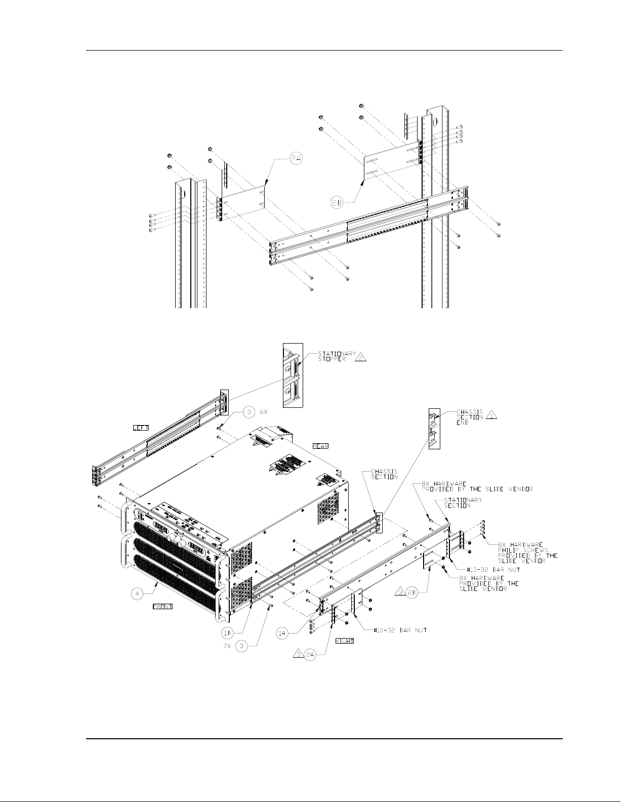
2.3.2 K550212-01 ASSEMBLY STEPS (OPTION KIT)
Figure 2-1. Rack Mount Assembly for 3U Models
2-4 M550221-01 Rev AA
Page 27
Sorensen SGI Series Installation
WARNING!
A minimum two-person lift is required for the 3U SGA Series power
supply, which weighs up to 110 lb (50 kg) depending on the model.
Refer to Figure 2-1 for 3U rack mount assembly drawing for the following
instructions:
1. Install the slide sections, 1C , on both sides of the power supply chassis with
screws (three on left side and four on right side). Ensure that the latch spring
orientation is as shown in Note 1 .
2. Install the brackets, 2A and 2B , to the stationary slide sections, 1A , with the
hardware provided by the slide supplier as shown in Note 3 .
3. Ensure that stopper orientation of slide sections, 1B , is as shown in Note 2 .
Adjust the location of the mounting brackets as required for the particular type
of cabinet vertical rails utilized.
4. Mount the stationary slide sections, 1A , (with brackets already installed) into
the cabinet using appropriate hardware (e.g. bar nuts, cage nuts, clip nuts),
while ensuring that they are level front to back and left to right of the cabinet
rails.
5. Insert power supply chassis with slide sections, 1C , into slide sections, 1B .
6. Secure the front panel of the power supply chassis to the cabinet rack rails
using the screws provided in the ship kit.
M550221-01 Rev AA 2-5
Page 28
Installation Sorensen SGI Series
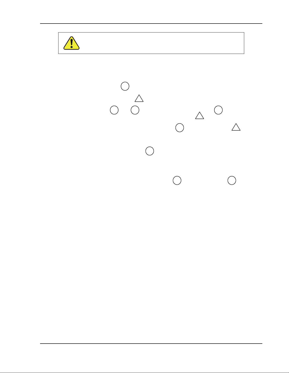
2.3.3 K550213-01 ASSEMBLY STEPS (OPTION KIT)
Figure 2-2. Rack Mount Assembly for 6U Models
2-6 M550221-01 Rev AA
Page 29
Sorensen SGI Series Installation
WARNING!
A minimum two-person lift is required for the 3U SGA Series power
supply, which weighs up to 110 lb (50 kg) depending on the model.
A minimum three-person lift is required for the 6U SGA Series unit,
which weighs up to 170 lb (77 kg) depending on the model.
WARNING!
A minimum three-person lift is required for the 6U SGA Series power
supply, which weighs up to 170 lb (77 kg) depending on the model.
Refer to Figure 2-2 for 6U rack mount assembly drawing for the following
instructions:
1. Install the slide sections, 1B , on both sides of the power supply chassis with
screws (six on left side and seven on right side). Ensure that the section end
orientation is as shown in Note 1 .
2. Install the brackets, 2A and 2B , to the stationary slide sections, 1A , with the
hardware provided by the slide supplier as shown in Note 3 . Ensure that the
stopper orientation is as shown in Note 2 . Adjust the location of the mounting
brackets as required for the particular type of cabinet vertical rails utilized.
3. Mount the stationary slide sections, 1A , (with brackets already installed) into
the cabinet using appropriate hardware (e.g. bar nuts, cage nuts, clip nuts),
while ensuring that they are level front to back and left to right of the cabinet
rails.
4. Insert power supply chassis with slide sections, 1B , into slide sections, 1A .
5. Secure the front panel of the power supply chassis to the cabinet rack rails
using the screws provided in the ship kit.
.
2.3.4 Chassis Removal from Rack
The slides have a front disconnect feature and lock at full extension. To
disconnect and remove the chassis from the rack, depress the flat steel spring
(located on the slides) inward, and pull the chassis forward. To return the
chassis back into the rack from full extension, depress the flat steel spring
(located on the slides) inward, and push the chassis back.
When the chassis is at full extension, the flat springs are located behind the
front rack rails. Retract the springs with a flat blade screwdriver or similar
device to release from lock-out or to remove the chassis from the rack.
M550221-01 Rev AA 2-7
Page 30
Installation Sorensen SGI Series
WARNING!
High voltage present at rear panel! Risk of electrical shock. Do not remove
protective covers on AC input or DC output. Refer to qualified service personnel.
WARNING!
The input and output voltages at the rear panel of the unit might be HAZARDOUS
LIVE. When rack-mounting or panel-mounting the unit, suitable safeguards must
be taken by the installer to ensure that HAZARDOUS LIVE voltages are not
OPERATOR accessible. OPERATOR access should only be to the front panel of
the unit.
WARNING!
A safety disconnect device for the AC mains input must be installed so that it is
readily accessible to the user
WARNING!
A properly sized input overcurrent protection device must be installed at the AC
mains input, either a circuit breaker or fuse having a rating of 25% over the
maximum AC input line currents listed in Table 2–1.
WARNING!
To prevent an electrical shock hazard, a safety ground wire must be connected
from the safety ground stud on the rear panel to the AC mains ground.
CAUTION!
Under no condition should the negative output terminal exceed 300V to earth
ground. Floating the negative output terminal subjects the internal control circuitry
of the power supply to the same potential as present at the negative output
terminal. In a unit with the standard Non-Isolated Analog Interface, the signals of
control connector, J1, would float at the same potential as the negative output
terminal. Damage might occur if the signals of the Non-Isolated Analog control
connector are connected to an external ground referenced device, due to
unintentional ground loop currents that this connection could generate. To correct
ground loop problems, it is advised to use the optional Isolated Analog Interface in
order to isolate the external signals from the internal control circuitry of the supply.
Refer to Section 1.2.2 of the specifications for additional information.
2.4 Input/Output Connections
Refer to Table 2–1 for AC input current requirements and Section 1.2.3 for
output current specifications. Table 2–3 provides information on the external
input and output connections for the SGI Series models. Table 2–4 provides
input connections descriptions and Table 2–5 provides output connection
descriptions. Refer to Table 2–6 for input/output lug recommendations. The
recommended tools for crimping and extraction of the sense connector pins
are listed below in Table 2–7.
2-8 M550221-01 Rev AA
Page 31

Sorensen SGI Series Installation
Model Ratings
Input Line Current, A (RMS)*
Voltage
Model
AC Input
Option
Code
Input
Voltage,
VAC
5 kW
10 kW
15 kW
20 kW
25 kW
30 kW
40V-1000V
C
208/230
20
39
59
79
98
118
D
380/400
11
22
32
43
54
65 E 440/480
9
19
28
37
47
56
4 kW
8 kW
12 kW
5 kW
10 kW
15 kW
10V-15V
C
208/230
16
32
47
N/A
N/A
N/A D 380/400
9
17
26
N/A
N/A
N/A E 440/480
7
15
22
N/A
N/A
N/A
20V-30V
C
208/230
N/A
N/A
N/A
20
39
59
D
380/400
N/A
N/A
N/A
11
22
32 E 440/480
N/A
N/A
N/A 9 19
28
* AC input current could vary as a result of actual power factor; refer to specifications section for
power factor dependency
Model Ratings
Input Line Current, A(RMS)*
Voltage
Model
AC Input
Option
Code
Input
Voltage,
VAC
5 kW
10 kW
15 kW
20 kW
25 kW
30 kW
40V-800V
C
208/230
24
47
71
95
118
142
D
380/400
13
27
40
54
67
81
E
440/480
12
24
36
49
61
73
* AC input current varies depending on actual power factor; refer to specifications section on power
factor
Connector
Function
Connection
L1 – AC, L2 – AC, L3 – AC,
Chassis - GND
AC input power; see Table 2–4
AC mains 3-phase
input
Pos. Bus Bar,
Neg. Bus Bar
DC output power; see Table 2–5
User load
Analog Interface
Connector (J1)
Control interface; see Table 3–5
User controller
Remote Sense Connector
Remote voltage sensing; see Section 3.14
Output load
Parallel In/Out
Parallel operation; see Section 3.16
Master/Slave units
Table 2–1. Maximum AC Current Ratings, PFC Models
Table 2–2. Maximum AC Current Ratings, Non-PFC Models
Table 2–3. Input/Output Connectors
M550221-01 Rev AA 2-9
Page 32
Installation Sorensen SGI Series
Power Supply Type
Connections
Connection Description
4 kW to 15 kW, 3U
AC Input
Feed-Through terminal block with
compression terminals
20 kW to 30 kW, 6U
AC Input
Bus Bar with holes for 1/4"–20 bolts
All 3U and 6U
Chassis Safety Ground
1/4-20 stud
CAUTION!
To prevent damage to the AC input connector of the 3U units, follow torque
specifications, and, if a wire ferrule is used, ensure that it is properly sized
and that it has been crimped with the appropriate ferrule crimping tool.
Power Supply Type
Connection Description
4 kW to 15 kW, 10V-30V models
Bus bars with two holes for 1/2” bolts on each terminal
(POS. and NEG.)
5 kW to 15 kW, 40V-1000V models
40V-600V models: bus bars with single holes for 3/8" bolts
on each terminal (POS. and NEG.)
800V and 1000V models: 1/4-20 studs for each terminal
(POS. and NEG.)
20 kW to 30 kW
Bus bars with single holes for 3/8" bolts for each terminal
(POS. and NEG.)
Manufacturer
Low Current
High Current
Panduit
P, PV, or PN series, or
equivalent
Standard stranded wire: LCA Series, or equivalent
Flexible stranded wire: LCAX Series, or equivalent
Note:
Contact lug manufacturer for recommended crimping tool.
Tool
Manufacturer
Manufacturer P/N
Crimping
Molex
11-01-0197
Extracting
Molex
11-03-0044
Table 2–4. Input Terminal Connections
AC Input Connector for 3U Models
Recommended torque for the AC input connector screws: 17.7 in-lb to 20.4 in-
lb (2 Nm to 2.3 Nm).
Wire ferrules are recommended, properly sized to match the wire gauge; use
appropriate crimp tool for the ferrule size.
Wire insulation should be stripped to 5/8”, maximum.
For more information on the AC input connector, refer to the manufacturer
(Phoenix Contact) part number HDFKV 16 at their website,
www.phoenixcontact.com.
Table 2–5. Output Terminal Connections
Table 2–6. Recommended Lugs
Table 2–7. Recommended Sense Connector Tools
2-10 M550221-01 Rev AA
Page 33
Sorensen SGI Series Installation
CAUTION!
Cables with Class B or C stranding should be used. Fine-stranded
(flexible) cables should not be used unless crimp-on lugs or ferrules
are used that are approved for fine-stranded cables.
Size
Temperature Rating of Copper Conductor
AWG
60°C
75°C
85°C
90°C
Types: RUW,
T, TW, UF
Types: FEPW,
RHW, RH, RUH,
THW, THWN,
XHHW, USE, ZW
Types: V, MI
Types: TA, TBS,
SA, AVB, SIS, FEP,
FEPB, RHH, THHN,
XHHW
Current Rating, A(RMS)
14
20
20
25
25
12
25
25
30
30
10
30
35
40
40 8 40
50
55
55 6 55
65
70
75 4 70
85
95
95 3 85
100
110
110 2 95
115
125
130
1
110
130
145
150
0
125
150
165
170
00
145
175
190
195
000
165
200
215
225
0000
195
230
250
260
2.5 Wire Selection
Care must be taken to properly size all conductors for the input and output of
the power supply. This section provides guidance in the selection of wire size.
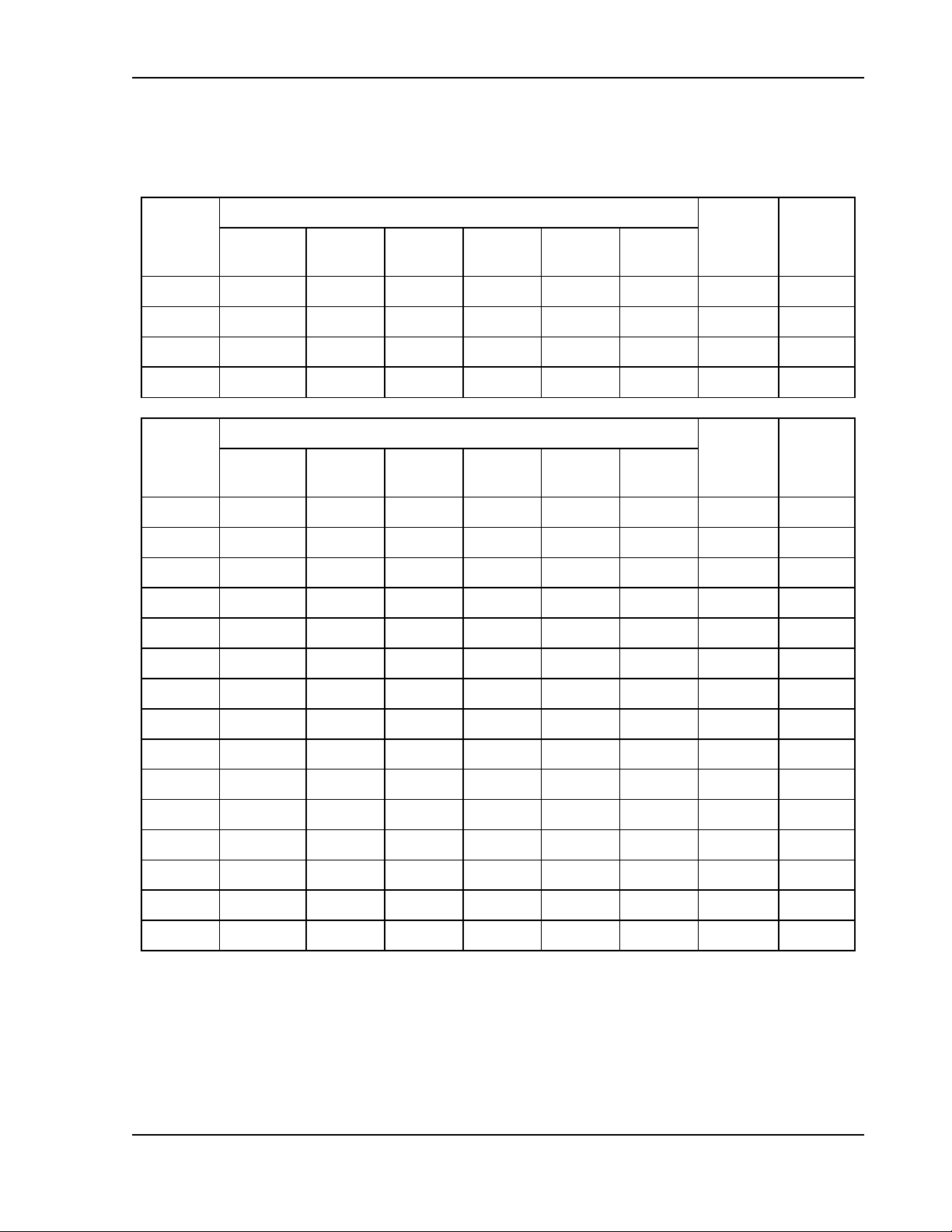
2.5.1 Wire Size
The tables below will assist in determining the appropriate wire size for both
the input and output connections. Table 2–8 gives minimum recommended
wire size; these recommendations are for copper wire only. This table is
derived from the National Electrical Code, and is for reference only. Local laws
and conditions may have different requirements. For higher ratings, wires can
be paralleled; refer to the National Electrical Code for guidelines.
Table 2–8. Minimum Wire Size
M550221-01 Rev AA 2-11
Page 34

Installation Sorensen SGI Series
When determining the optimum cable specification for your power applications,
the same engineering rules apply whether at the input or output of an
electrical device. Thus, this guide applies equally to the AC input cable and DC
output cable for this power supply and application loads.
Power cables must be able to safely carry maximum load current without
overheating or causing insulation degradation. It is important to power supply
performance to minimize IR (voltage drop) loss within the cable. These losses
have a direct effect on the quality of power delivered to and from instruments
and corresponding loads.
When specifying wire gauge, consider derating due to operating temperature
at the wire location. Wire gauge current capability and insulation performance
drops with the increased temperature developed within a cable bundle and
with increased environmental temperature. Thus, short cables with generously
derated gauge and insulation properties are recommended for power source
applications.
Be careful when using published commercial utility wiring codes. These codes
are designed for the internal wiring of homes and buildings and accommodate
the safety factors of wiring loss, heat, breakdown insulation, aging, etc.
However, these codes consider that up to 5% voltage drop is acceptable. Such
a loss directly detracts from the quality performance specifications of this SG
power supply. Also, consider how the wiring codes apply to bundles of wire
within a cable arrangement.
In high performance applications requiring high inrush/ transient currents,
additional consideration is required. The cable wire gauge must accommodate
peak currents developed at peak voltages, which might be up to ten times the
average current values. An underrated wire gauge adds losses, which alter the
inrush characteristics of the application and thus the expected performance.
Table 2–9 presents wire resistance and resulting cable voltage drop at
maximum rated current, with the wire at 20°C. Copper wire has a temperature
coefficient of α = 0.00393Ω/°C at t1 = 20°C, so that at an elevated
temperature, t2, the resistance would be R2 = R1 (1 + α (t2 - t1)).
2-12 M550221-01 Rev AA
Page 35
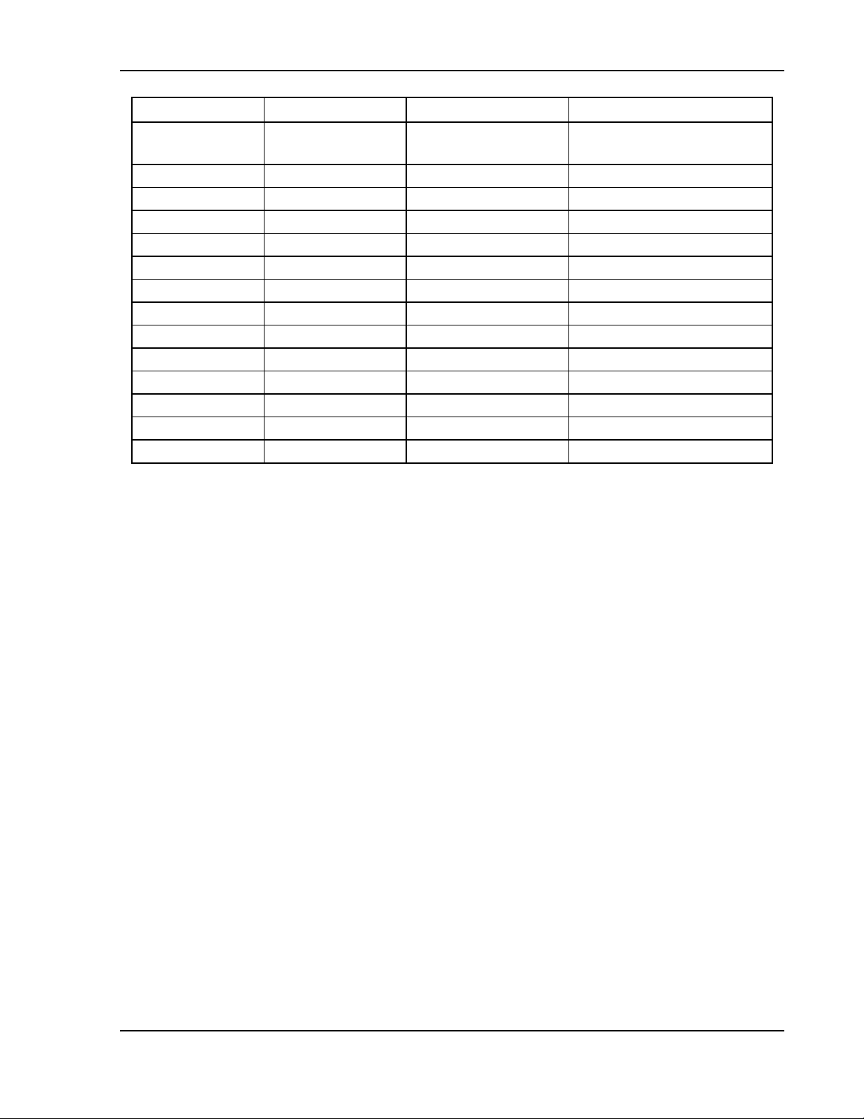
Sorensen SGI Series Installation
Column 1
Column 2
Column 3
Column 4
Size, AWG
A(RMS)
Ohms/100 Ft
(One Way)
Voltage Drop/100 Ft
(Column 2 x Column 3)
14
20
0.253
5.06
12
25
0.156
3.90
10
30
0.999
3.00
8
40
0.063
2.52
6
55
0.040
2.20
4
70
0.025
1.75
3
85
0.020
1.70
2
95
0.016
1.52
1
110
0.012
1.32
0
125
0.010
1.25
00
145
0.008
1.16
000
165
0.006
0.99
0000
195
0.005
0.98
Table 2–9. Wire Resistance and Voltage Drop, 20°C
M550221-01 Rev AA 2-13
Page 36

Installation Sorensen SGI Series
Power
Supply
Sense (+)
Sense (-)
Out (+)
Out (-)
Battery
Application
Inductive Load
Application
OR
Freewheel
Diode
2.6 LOAD CONSIDERATIONS
This section provides guidelines for incorporating protective diode networks at
the output of the power supply to prevent damage while driving inductive loads
or loads having stored energy that could be circulated back to the power
supply.
2.6.1 Inductive and Stored-Energy Loads
To prevent damage to the power supply from inductive voltage kickback,
connect an anti-parallel diode (rated at greater than the supply’s output voltage
and current) across the output: Connect the cathode to the positive output and
the anode to return.
Where positive load transients, such as back EMF from a motor might occur,
or stored energy is present such as a battery, a second blocking diode in
series with the output is recommended to protect the power supply.
BLOCKING AND ANTI-PARALLEL DIODES
Ensure that the chosen components are suitably rated for the particular
inductance and energy to be dissipated. The Peak Reverse Voltage ratings
should be a minimum of 2 times the Power Supply maximum output voltage.
The Continuous Forward Current ratings should be a minimum of 1.5 times the
power supply maximum output current. A heatsink may be required to
dissipate the power caused by flow of current.
2-14 M550221-01 Rev AA
Figure 2-3. Diode Connection
Page 37

Sorensen SGI Series Installation
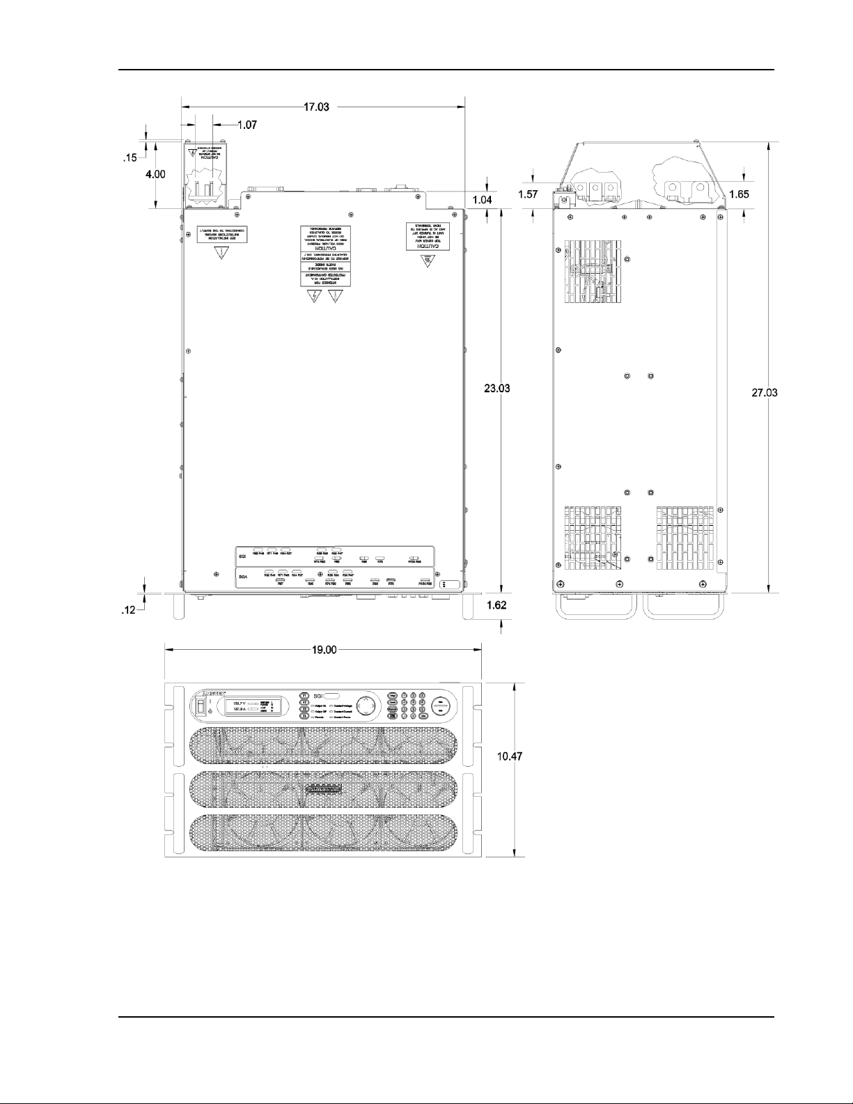
2.7 Outline Drawings
Figure 2-4 through Figure 2-7 show the outlines and overall dimensions for
installation of the 3U and 6U models of the SGI Series power supplies.
Figure 2-8 through Figure 2-16 show locations of rear panel connectors.
Figure 2-17 shows protective covers for the AC input and DC output of the 3U
10V-30V models.
M550221-01 Rev AA 2-15
Page 38

Installation Sorensen SGI Series
Figure 2-4. Installation Drawing, 3U Models 10V-30V
2-16 M550221-01 Rev AA
Page 39
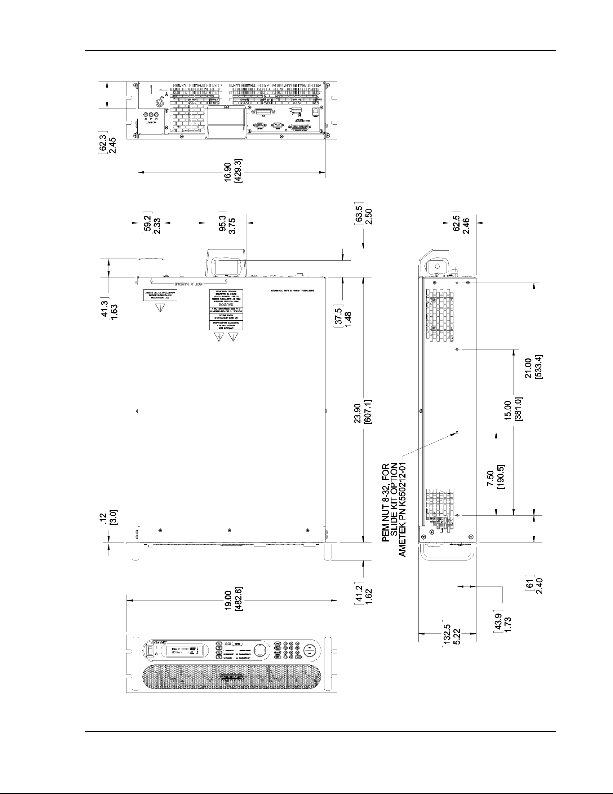
Sorensen SGI Series Installation
Figure 2-5. Installation Drawing, 3U Models 40V-600V
M550221-01 Rev AA 2-17
Page 40
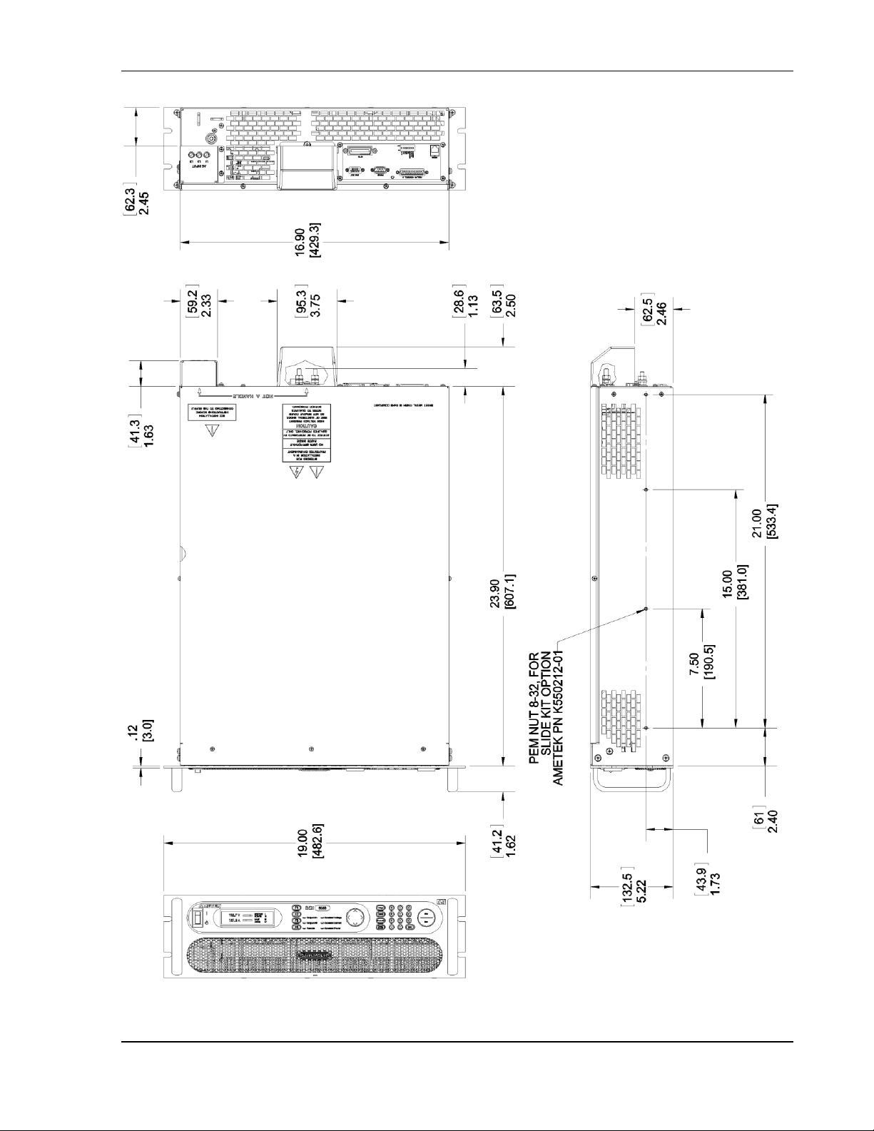
Installation Sorensen SGI Series
Figure 2-6. Installation Drawing, 3U Models 800V and 1000V
2-18 M550221-01 Rev AA
Page 41
Sorensen SGI Series Installation
Figure 2-7. Installation Drawing, 6U Models 20kW-30kW
M550221-01 Rev AA 2-19
Page 42

Installation Sorensen SGI Series
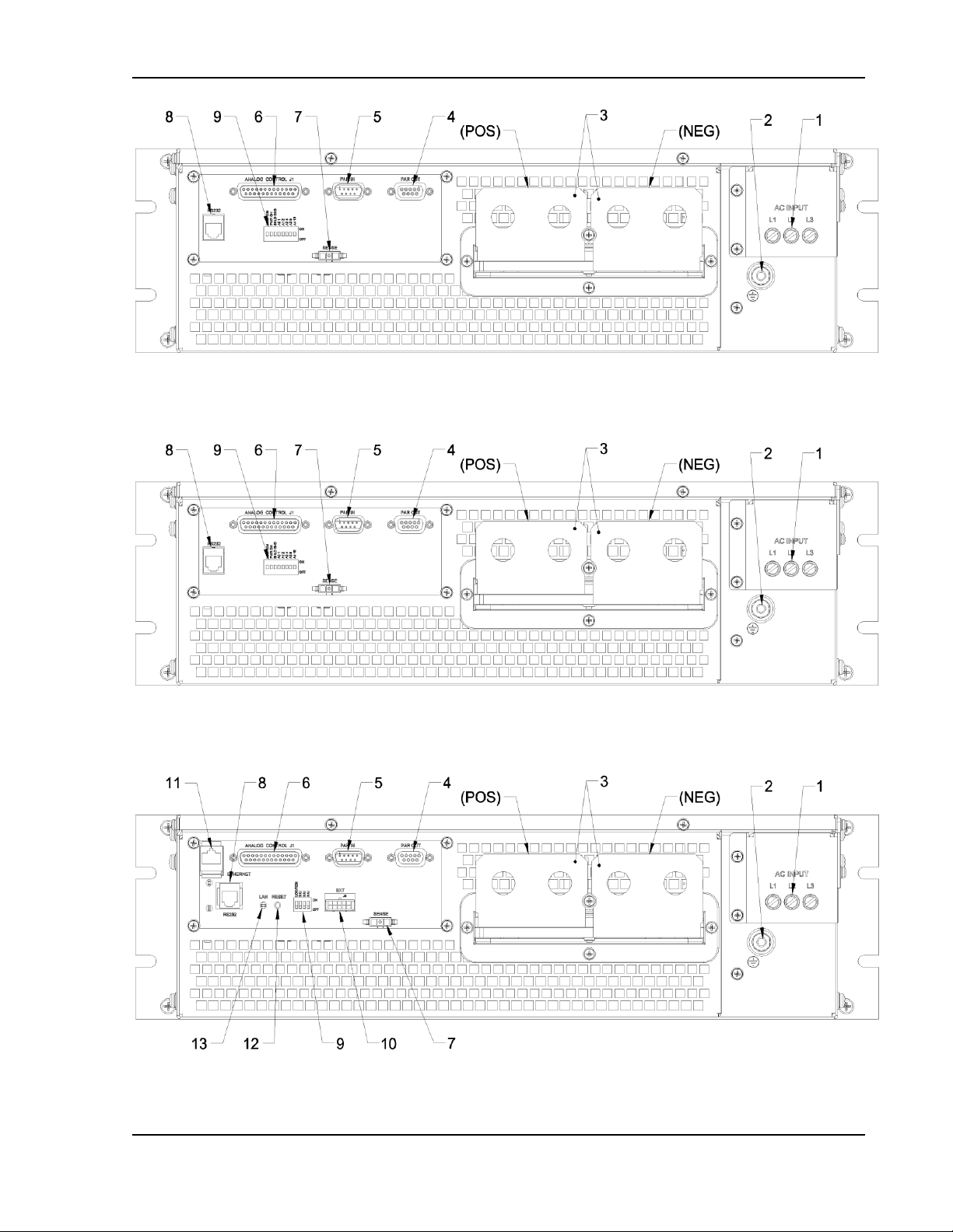
Figure 2-8. Rear Panel, Standard, 3U Models 10V-30V
2-20 M550221-01 Rev AA
Page 43
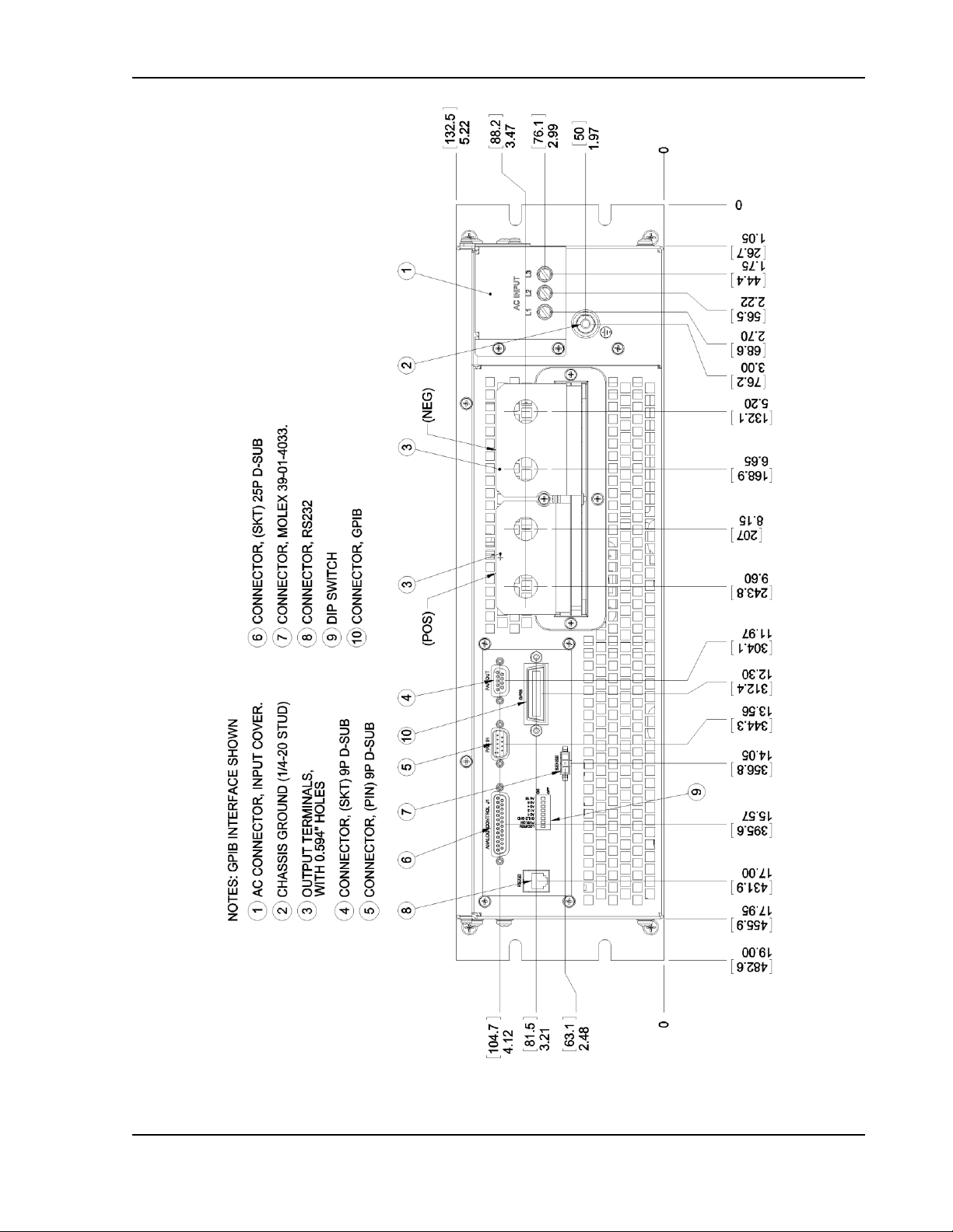
Sorensen SGI Series Installation
Figure 2-9. Rear Panel, GPIB Option, 3U Models 10V-30V
M550221-01 Rev AA 2-21
Page 44

Installation Sorensen SGI Series
Figure 2-10. Rear Panel, Ethernet Option, 3U Models 10V-30V
2-22 M550221-01 Rev AA
Page 45

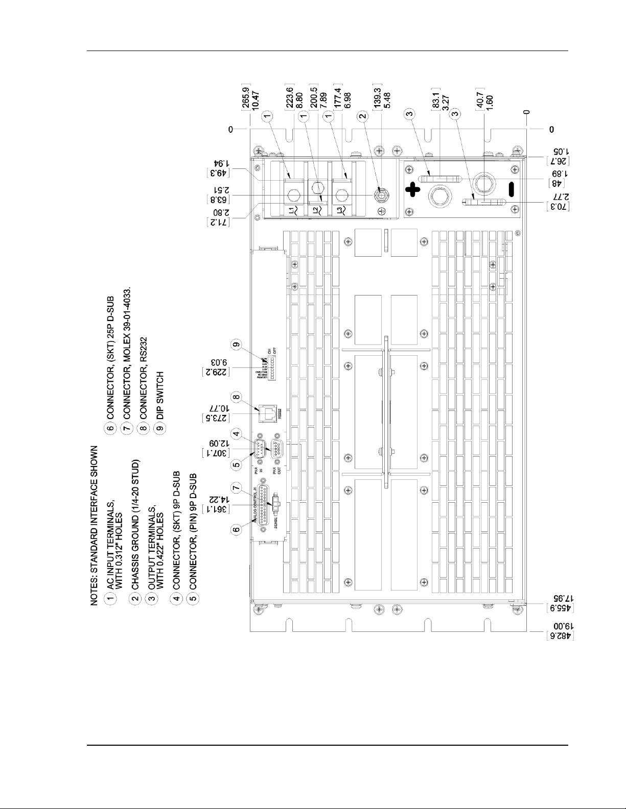
Sorensen SGI Series Installation
Figure 2-11. Rear Panel, Standard, 3U Models 40V-600V
M550221-01 Rev AA 2-23
Page 46

Installation Sorensen SGI Series
Figure 2-12. Rear Panel, GPIB Option, 3U Models 40V-600V
2-24 M550221-01 Rev AA
Page 47

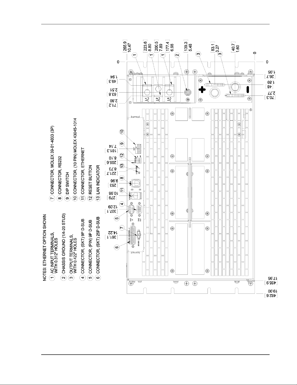
Sorensen SGI Series Installation
Figure 2-13. Rear Panel, Ethernet Option, 3U Models 800V and 1000V
M550221-01 Rev AA 2-25
Page 48
Installation Sorensen SGI Series
Figure 2-14. Rear Panel, Standard, 6U Models 20kW-30 kW
2-26 M550221-01 Rev AA
Page 49

Sorensen SGI Series Installation
Figure 2-15. Rear Panel, GPIB Option, 6U Models 20kW-30 kW
M550221-01 Rev AA 2-27
Page 50
Installation Sorensen SGI Series
Figure 2-16. Rear Panel, Ethernet Option, 6U Models 20kW-30 kW
2-28 M550221-01 Rev AA
Page 51

Sorensen SGI Series Installation
Figure 2-17. Instructions for Assembly of AC and DC Covers
M550221-01 Rev AA 2-29
Page 52

Installation Sorensen SGI Series
This page intentionally left blank.
2-30 M550221-01 Rev AA
Page 53

3.1 Introduction
The SGI Series adds powerful functionality and sequence programming to the
SG family of DC power supplies. The graphical display, front panel keyboard,
and context sensitive keys make setup of the sophisticated functions simple and
easy. The following sections provide detailed information on the controls and
indicators, programming conventions, and the front panel menu structure of the
SGI Series.
SECTION 3
OPERATION
3.1.1 Front/Rear Panels
Figure 3-1 shows the front panel of the 3U models; the 6U models have the
same controls and indicators. Figure 3-2 through Figure 3-10 show the rear
panels of the 3U and 6U models, with their connectors and controls.
Figure 3-1. Front Panel Controls and Indicators (3U Model Shown)
M550221-01 Rev AA 3-1
Page 54

Calibration and Verification Sorensen SGI Series
WARNING!
The power-up factory default state is output enabled, where the
output will be energized at the settings of voltage and current.
Item Reference
Functional Description
1
ON/OFF Switch
Two–position switch turns the power supply on and off.
WARNING!
OFF position does not remove AC input
from internal circuits or input terminal
blocks. Disconnect external AC input
before servicing unit.
2
Front Panel Display
256 x 64 graphic vacuum fluorescent display for menus,
settings and functions.
3
Function Keys, F1-F4
Context-sensitive, soft-keys execute commands specified on
front panel display by its corresponding label.
4
LED Mode Indicators:
Indicates the mode that is active.
Output On
Power to output terminals is present.
Output Off
Power to output terminals is disabled.
Remote
Supply presently controlled by remote digital interface.
Constant Voltage
Power supply presently in Constant-Voltage mode.
Constant Current
Power supply presently in Constant-Current mode.
Constant Power
Power supply presently in Constant-Power mode.
5
NAVPAD
Navigation Pad navigates between and within screens; also
used for increment/decrement control to make live updates;
see Section 3.5 Section 3.6.
6
Programming Keys:
Specific function keys, also called hard-coded keys.
Voltage
Jumps directly to Voltage programming.
Current
Jumps directly to Current programming.
Overvolt
Jumps directly to Overvoltage Protection programming.
7
Output On/Off Key
Enables/disables power to the output terminals.
8
Numeric Keys 0-9
Used to enter specific values for editable items.
9
ESC Key (escape)
Cancels numeric input and/or returns to previous menu.
10
Menu/Enter
“Menu” returns to Home Menu Page 1; see Section 3.7.
“Enter” sets a value that was input via numeric keys.
Table 3–1. Front Panel Controls and Indicators
3-2 M550221-01 Rev AA
Page 55
Sorensen SGI Series Calibration and Verification
Figure 3-2. Rear Panel Interface, Standard, 3U Models 10V-30V
Figure 3-3. Rear Panel Interface, GPIB Option, 3U Models 10V-30V
Figure 3-4. Rear Panel Interface, Ethernet Option, 3U Models 10V-30V
M550221-01 Rev AA 3-3
Page 56
Calibration and Verification Sorensen SGI Series
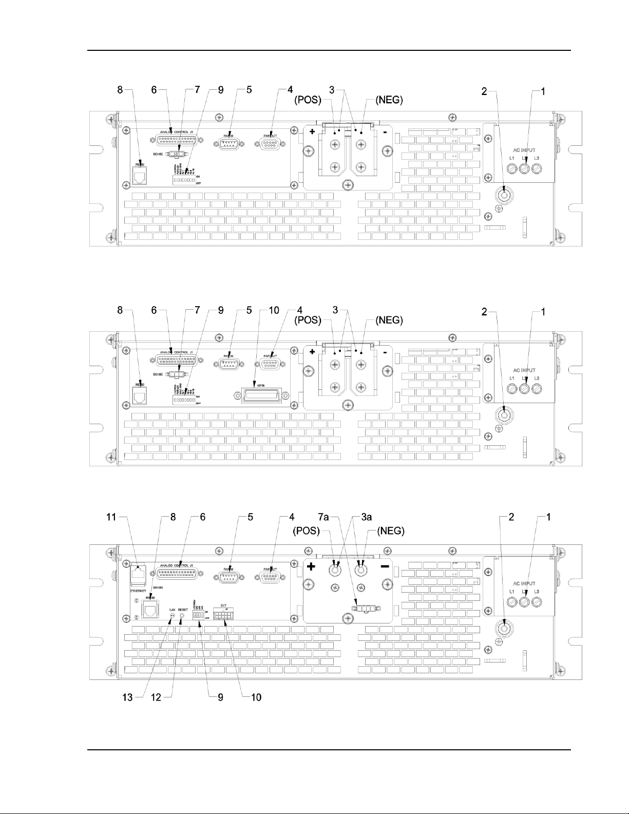
Figure 3-5. Rear Panel Interface, Standard, 3U Models 40V-600V
Figure 3-6. Rear Panel Interface, GPIB Option, 3U Models 40V-600V
Figure 3-7. Rear Panel Interface, Ethernet Option, 3U Models 800V and 1000V
3-4 M550221-01 Rev AA
Page 57

Sorensen SGI Series Calibration and Verification
Figure 3-8. Rear Panel Interface, Standard, 6U Models 20kW-30kW
Figure 3-9. Rear Panel Interface, GPIB Option, 6U Models 20kW-30kW
Figure 3-10. Rear Panel Interface, Ethernet Option, 6U Models 20kW-30kW
M550221-01 Rev AA 3-5
Page 58

Calibration and Verification Sorensen SGI Series
Item
Reference
Functional Description
1
AC Input Connectors
Connection for 3-phase AC.
2
AC Input Safety Ground
Connection for safety ground wire.
3
DC Output Bus Bars
Positive (+) and negative (–) outputs.
3a
HV DC Output Studs
Positive (+) and negative (–) outputs for 800V and
1000V models only.
4
PAR OUT
Parallel Out connector of master unit for configuring
parallel operation of units when connected to Parallel In
connector of slave unit; see Section 3.16 .
5
PAR IN
Parallel In connector of slave unit for configuring parallel
operation of units when connected to Parallel Out
connector of master unit; see Section 3.16.
6
ANALOG CONTROL
Remote Analog Interface connector, J1, for
programming and monitoring signals of output, status
indication, and remote shutdown signals; see Table 3–5
for individual pin descriptions.
7
SENSE Connector
Input connector, J3, for remote sensing of voltage at the
load to compensate for line drop in load cables; see
Section 3.14.
7a
HV SENSE Connector
Input connector,J3, for remote sensing of voltage at the
load to compensate for line drop in load cables, 800V
and 1000V models only; see Section 3.14.
8
RS-232 Connector†
RS-232 connector for remote digital control.
9
Configuration Switch†
Eight-position DIP switch to configure the digital
interface of the unit
Refer to Figure 3-2, Figure 3-5, and Figure 3-8Error! Reference source not found..
†
Refer to the Programming Manual for details on the digital interface.
Table 3–2. Rear Panel Connectors and Controls, Standard
3-6 M550221-01 Rev AA
Page 59
Sorensen SGI Series Calibration and Verification
Item
Reference
Functional Description
1
AC Input Connectors
Connection for 3-phase AC.
2
AC Input Safety Ground
Connection for safety ground wire.
3
DC Output Bus Bars
Positive (+) and negative (–) outputs.
3a
HV DC Output Studs
Positive (+) and negative (–) outputs for 800V and
1000V models only.
4
PAR OUT
Parallel Out connector of master unit for configuring
parallel operation of units when connected to Parallel In
connector of slave unit; see Section 3.16.
5
PAR IN
Parallel In connector of slave unit for configuring parallel
operation of units when connected to Parallel Out
connector of master unit; see Section 3.16.
6
ANALOG CONTROL
Remote Analog Interface connector, J1, for
programming and monitoring signals of output, status
indication, and remote shutdown signals; see Table 3–5
for individual pin descriptions.
7
SENSE Connector
Input connector, J3, for remote sensing of voltage at the
load to compensate for line drop in load cables; see
Section 3.14.
7a
HV SENSE Connector
Input connector,J3, for remote sensing of voltage at the
load to compensate for line drop in load cables, 800V
and 1000V models only; see Section 3.14
8
RS-232 Connector†
RS-232 connector for remote digital control.
9
Configuration Switch†
Eight-position DIP switch to configure the digital
interface of the unit
10
GPIB Connector
†
GPIB connector for remote digital control.
Refer to Figure, Figure 3-6, and Figure 3-9.
†
Refer to the Programming Manual for details on the digital interface.
Table 3–3. Rear Panel Connectors and Controls, GPIB Option
M550221-01 Rev AA 3-7
Page 60

Calibration and Verification Sorensen SGI Series
Item
Reference
Functional Description
1
AC Input Connectors
Connection for 3-phase AC.
2
AC Input Safety Ground
Connection for safety ground wire.
3
DC Output Bus Bars
Positive (+) and negative (–) outputs.
3a
HV DC Output Studs
Positive (+) and negative (–) outputs for 800V and
1000V models only.
4
PAR OUT
Parallel Out connector of master unit for configuring
parallel operation of units when connected to Parallel In
connector of slave unit; see Section 3.16.
5
PAR IN
Parallel In connector of slave unit for configuring parallel
operation of units when connected to Parallel Out
connector of master unit; see Section 3.16.
6
ANALOG CONTROL
Remote Analog Interface connector, J1, for
programming and monitoring signals of output, status
indication, and remote shutdown signals; see Table 3–5
for individual pin descriptions.
7
SENSE Connector
Input connector, J3, for remote sensing of voltage at the
load to compensate for line drop in load cables; see
Section 3.14.
7a
HV SENSE Connector
Input connector,J3, for remote sensing of voltage at the
load to compensate for line drop in load cables, 800V
and 1000V models only; see Section 3.14.
8
RS-232 Connector†
RS-232 connector for remote digital control.
9
Configuration Switch†
Four–position DIP switch to configure the digital
interface of the unit
10
External User
Connector†
Input/Output connector for external auxiliary digital
control signals.
11
ETHERNET Connector†
Ethernet connector for remote digital control.
12
RESET Switch†
Reset switch to return configuration parameters to
factory default settings; must be depressed until LAN
LED is blinking.
13
LAN†
LED indicator: continuously on indicates Ethernet
connection; off indicates no Ethernet connection;
blinking indicates Instrument ID.
Refer to Figure 3-4, Figure 3-7, and Figure 3-10.
†
Refer to the Programming Manual for details on the digital interface.
Table 3–4. Rear Panel Connectors and Controls, Ethernet Option
3-8 M550221-01 Rev AA
Page 61

Sorensen SGI Series Calibration and Verification
WARNING!
The power-up factory default state is output enabled, and the output will
be energized with the settings of voltage and current at zero. At initial
power-on a screen is displayed with a warning that the output will be
enabled after countdown of a 10-second timer; during this state, the
output Voltage and Current are programmed to zero, the Overvoltage
Protection (OVP) is set to maximum, and the Output State is OFF. After
the 10-second timer has elapsed, the Output State is changed to ON.
3.2 Basic Operation and Output Verification
This section provides an overview and examples of front panel programming,
Default Programming menu operation, and initial functional tests for the SGI
Series power supply.
The SGI Series power supply is shipped from the factory configured for front
panel (local) voltage/current/OVP control, and with the remote sense not
connected (default to internal local voltage sensing at chassis output
terminals). The remote sense leads must be connected externally by the user
to achieved performance specifications. The Analog Control connector is
supplied with a mating connector which has the remote output ON/OFF control
signals jumpered for ON (Pin-5 shorted to Pin-6) in order to allow the output to
be enabled.
3.2.1 Initial Setup
Before connecting the unit to the AC mains, ensure that the front panel
ON/OFF power switch is in the OFF position. Check the Analog Control (J1)
mating connector on the rear panel to verify that Pins 5 and 6 (Remote Output
On/Off) are shorted together. This is the default configuration installed from
the factory. This jumper allows the output of the supply to be enabled from the
front panel when the Output On/Off button is pressed.
3.2.2 Default Programming Menu
The following subsections describe operation in Constant-Voltage Mode,
Constant-Current Mode, and Overvoltage Protection (OVP) using the Default
Programming Menu for input of setpoints.
M550221-01 Rev AA 3-9
Page 62

Calibration and Verification Sorensen SGI Series
3.2.3 Constant-Voltage Mode Operation
In Constant-Voltage mode operation, the output voltage is regulated at the
programmed value while the output current varies with the load requirements.
The voltage could be programmed either through the front panel or by the
remote analog voltage programming input; see Section 3.11. To verify
operation in Constant-Voltage mode, follow these steps:
1. Ensure that there is no load connected to the output.
2. Ensure that the remote sense is connected to the output terminals.
3. Connect a digital voltmeter (DVM) across the rear panel positive and
negative output terminals, observing the correct polarity. Make sure the
DVM is in the DC voltage mode and the range is adequate to handle the
full-scale voltage of the power supply.
4. Apply power to the AC mains input, and turn on the power supply.
5. If the default power-on state had previously been configured to be OFF,
when the supply reaches the Home menu Page 1, enable the output by
pressing “Output On/Off”.
6. Enter the Default Programming menu by pressing either of the
voltage, current or overvoltage front panel keys:
7. Program the Current to 10% of rated output (this programs the
current above zero to enable supplying output current while in the
constant-voltage mode). See Section 3.8.1 for more details on
programming.
8. Navigate to Voltage programming. With the Editing Arrow adjacent to
“Set Volt”, press and hold the NavPad up arrow and observe both the
front panel voltage display and the output of the DVM begin to accelerate
up. The output voltage should increase from 0 V to the maximum rated
voltage of the supply. The front panel display and DVM readings should
track within the accuracies of the meter and the front panel display.
9. Verify the front panel Constant Voltage Mode indicator is on.
10. Program the Voltage and Current back to zero.
11. Turn the power supply off.
12. If Constant-Voltage mode operation did not function as indicated above,
verify the setup and perform the check again. If the function continues to
fail, contact the factory for assistance.
3-10 M550221-01 Rev AA
Page 63

Sorensen SGI Series Calibration and Verification
3.2.4 Constant-Current Mode Operation
In Constant-Current mode operation, the output current is regulated at the
selected value while the output voltage varies with the load requirements. The
current could be programmed either through the front panel or by the remote
analog current programming input; see Section 3.10. To verify operation in
Constant-Current mode, follow these steps:
1. If the output had been previously energized, allow 5 minutes for the
output capacitors to discharge. Connect a high current DC ammeter
across the rear panel positive and negative output terminals, observing
the correct polarity. Select wire leads of sufficient current carrying
capacity and an ammeter range compatible with the units maximum rated
output current.
Note:
without measuring the current with an ammeter, but using only the front
panel meter, could be performed by shorting the output terminals
together.
2. Turn on the power supply.
3. If the default power-on state had been previously configured to be OFF,
when the supply reaches the Home menu Page 1, enable the
output by pressing “Output On/Off”.
4. Enter the Default Programming menu by pressing either of the
voltage, current, or overvoltage front panel keys:
5. Program the Voltage to 10% of rated output (this programs the voltage
above zero to enable supplying output voltage while in the constantcurrent mode). See Section 3.8.1 for more details on programming.
6. Navigate to Current programming. With the Editing Arrow adjacent to
“Set Curr”, press and hold the NavPad up arrow and observe both the
front panel current display and the output of the DC ammeter begin to
accelerate up. The output current should increase from 0 A to the
maximum rated current of the supply. The front panel display and DC
ammeter readings should track within the accuracies of the meter and the
front panel display.
Verification that the supply could source rated output current,
7. Verify the front panel Constant Current Mode indicator is on.
8. Program the Voltage and Current back to zero.
9. Turn the power supply off.
10. Allow 5 minutes for the output capacitors to discharge and disconnect the
ammeter or short from the output terminals.
M550221-01 Rev AA 3-11
Page 64

Calibration and Verification Sorensen SGI Series
11. If Constant-Current mode operation did not function as indicated above,
verify the setup and perform the check again. If the function continues to
fail, contact the factory for assistance.
3.2.5 Overvoltage Protection
The Overvoltage Protection (OVP) function allows the supply to shutdown the
output, if it were to exceed a preset voltage. This may be used to protect
sensitive circuits or loads from damage caused by an excessive voltage on the
output of the supply. The Overvoltage Protection (OVP) could be programmed
either through the front panel or by the remote analog OVP programming
input; see Section 3.12. To verify OVP operation, follow these steps:
1. Make sure there is nothing connected across the output terminals.
2. Turn on the power supply.
3. if the default power-on state had been previously configured to be OFF,
when the supply reaches the Home Menu Page 1, enable the output by
pressing “Output On/Off”.
4. Enter the Default Programming menu by pressing either of the
voltage, current, or overvoltage front panel keys:
5. Program the Current to 10% of rated output (this programs the
current above zero to enable supplying output current while in the
constant-voltage mode). See Section 3.8.1 for more details on
programming.
6. Navigate to OVP (Overvoltage) programming. The factory default setting
is approximately 110% of the maximum rated output of the supply. With
the Editing Arrow adjacent to “Set OVP”, press and hold the NavPad
down arrow and observe the front panel voltage display accelerate down.
Release the NavPad down arrow when the OVP is programmed to about
80-90% of the maximum rated output voltage value.
7. Navigate to Voltage programming. With the Editing Arrow adjacent to “Set
Volt”, press and hold the NavPad up arrow and observe the front panel
voltage display accelerate up. When the output voltage exceeds the OVP
trip point the OVP Warning screen will be display with the voltage level
reached at OVP trip. The Output State will be programmed to OFF, and
the voltage, current, and OVP settings will retain their previous settings.
8. Press (F4) and the fault screen will clear after 4 seconds. The Home
Menu Page 1 will be displayed, and the output will remain disabled.
3-12 M550221-01 Rev AA
Page 65

Sorensen SGI Series Calibration and Verification
9. Enter the Default Programming menu by pressing either
the voltage, current, or overvoltage front panel keys:
10. Program the OVP setting as appropriate for the
application as shown above. If OVP will not be used,
then “OVP set” programming may be set at maximum, approximately
110% of the rated output voltage of the supply.
11. If OVP mode did not function as indicated above, verify the setup and
perform the check again. If the function continues to fail, contact the
factory for assistance.
3.3 Initial Start-Up Displays
Upon initial start-up of unit, the following screens are displayed in sequence,
after initial splash screens which show manufacturer's information:
LAST CAL DATE
Displays for seven seconds, showing date that the unit was last calibrated.
See SG Series Programming Manual, P/N M550129-03, for calibration
information and how to update "Last Cal Date."
OUTPUT-ENABLED WARNING
Indicates number of seconds left in a 10-second countdown, warning the user
that the output will be enabled at the end of the countdown unless the process
is aborted by pressing the F1 key on the front panel. Once aborted, the output
remains off until the user enables it with the Output On/Off key: refer to
Section 3-1. This warning appears only if the unit is both in Local mode and
was last set and saved to enable the output at its next start-up. See
Section 3.8.2 for changing and saving the Power On (PwrOn) Output settings.
Note:
Factory default setting for Output at start-up is ON, output enabled.
HOME MENU, PAGE 1
Final screen to display upon initial start-up of the unit; it is from here that the
user may access all menu functions. See Menu Map, Section 3.7, for Home
M550221-01 Rev AA 3-13
Page 66
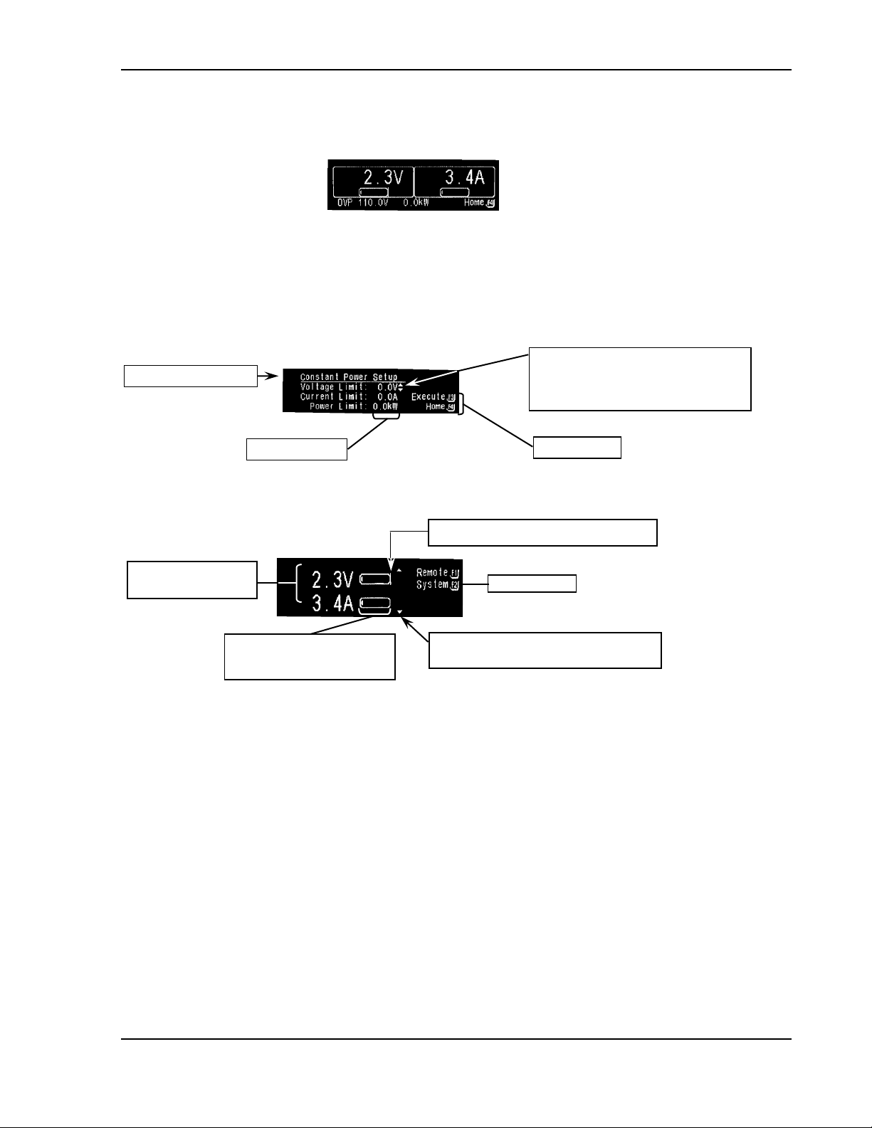
Calibration and Verification Sorensen SGI Series
Editing arrows for navigating to
editable items within a menu, and for
editing (see Navigation, Section 3.5,
and Editing, Section 3.6.
Function keys
Name of active screen
Editable values
Measured values for
Voltage and Current.
Graph indicates portion of
the present value relative to
the maximum value.
Navigation arrow moves to next page in
menu (see Navigation, Section 3.5).
Function keys
OVP Setpoint Indicator Bar (vertical bar).
Menu pages 1 through 3 and their submenus. See Functions, Section 3.8, for
access and program menu functions.
HOME TIMEOUT
Displays after 30 seconds of idle time in any of the three Home Menu pages; pressing
the F4 key on the front panel returns the display to Home Menu Page 1.
3.4 Display Elements
3-14 M550221-01 Rev AA
Page 67
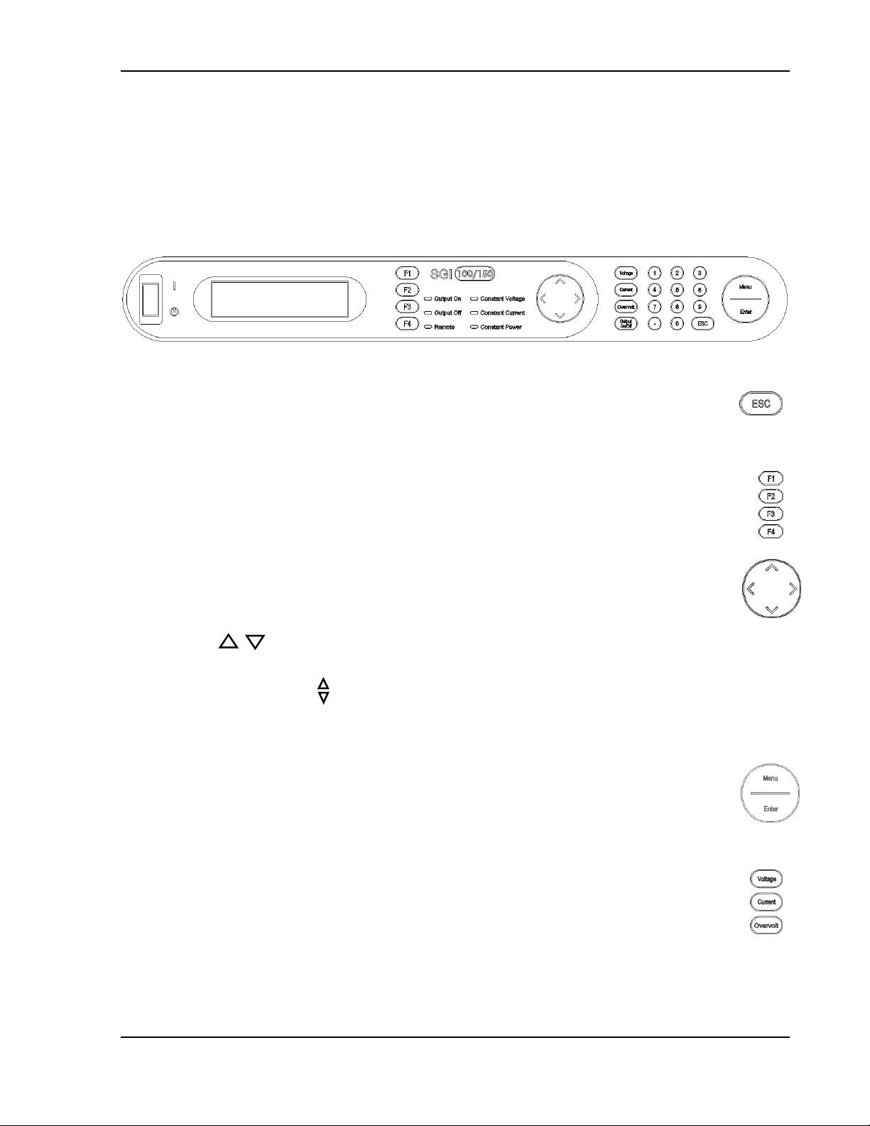
Sorensen SGI Series Calibration and Verification
3.5 Navigation
The primary keys used to navigate are: the escape key, ESC, the function
keys, F1-F4, the navigation pad, NavPad, the menu and enter key, Menu/Enter
and voltage, current, overvoltage protection programming keys, V/I/OVP Prog.
Their functions are as follows:
ESC: Probably the most important key to remember, escape works like the
back or return button in a browser, bringing the display back one menu level
to the previous menu. Continued pressing will eventually return the display
to the Home Menu. Escape is not functional in a Fault Screen.
F1-F4: To enter a function menu or execute a function, press the
corresponding Function key to the right of the function to be entered or
executed. Only those function keys defined within that menu will be
operational.
NavPad: Used to move between menu pages and between editable items
within a menu
o If a Navigation Arrow is displayed at the top and/or bottom of a screen,
pressing up/down on the NavPad allows the user to move
between pages within a menu.
o If the Editing Arrow is displayed, pressing left/right on the NavPad
allows the user to move between editable items within a menu. If a
screen has only one editable item, left/right arrow has no effect. See
Editing, Section 3.6.
Menu/Enter: Pressing “Menu” from any submenu jumps the display directly to
the Home Menu, Page 1, except in sequence or power mode; see note below.
Pressing “Enter” moves the editing arrow to the next editable item in the menu,
similar to the right arrow on the NavPad.
V/I/OVP Prog: Pressing the “Voltage,” “Current,” or “Overvolt” programming
key displays the Default Programming menu with the editing arrow at the
corresponding function in that menu - see note below.
Note:
programming keys do not function while running a sequence, paused in a
sequence, in sequence single step mode, or running in power mode.
M550221-01 Rev AA 3-15
The “Menu” key and the “Voltage,” “Current” and “Overvolt”
Page 68
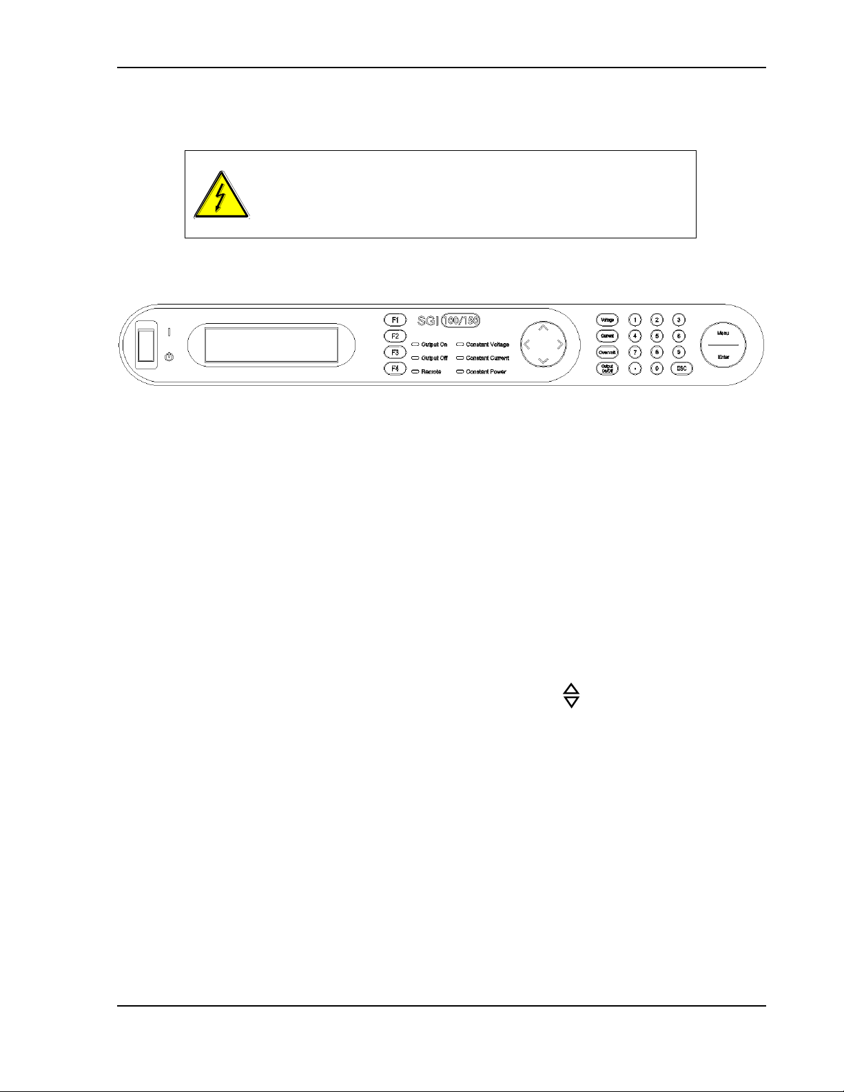
Calibration and Verification Sorensen SGI Series
WARNING!
While Output is enabled, the editable item being programmed
Voltage, Current, Overvoltage or Power is “Live Updated”, and
takes effect on the output terminals immediately.
3.6 Editing
The primary keys used to edit are: ESC, F1-F4, NavPad, Menu/Enter and
Keypad 0-9. Their functions are as follows:
ESC: In editing, ESC (escape) functions like the escape key on a keyboard.
While programming an editable item, the escape key can be used to clear the
entered value before it is accepted and takes effect. This leaves the program
function setting at the original value before editing began.
F1-F4: Not used to program editable items directly, Function keys may be
used to save, recall, cut, past, insert or delete edits made in some menus.
These functions will be indicated to the left of the function keys in the specific
menus they are used.
NavPad: The NavPad functions as an increment/decrement editing and “Live
Update” (Pressing Up/Down). “Live Update” means the value or item displayed
due to an edit change from the NavPad, is actively changing the operation of
the supply in real time when Output is On. This includes programming editable
items as well as scrolling through option lists within a menu.
Programming editable items: If an Editing Arrow is displayed,
pressing the NavPad up or down incrementally adjusts the editable
item value adjacent to the Editing Arrow by the least significant digit per
press in the respective direction. If the NavPad is pressed up or down
and held, the selected editable item will accelerate from set point to fullscale or from set point to zero, respectively, within 15 seconds. If the
output is enabled, the output terminals will “Live Update” with the
programmed changes.
Scrolling through option lists: Pressing the NavPad up or down
incrementally scrolls through the listed items available and “Live
Update” selects the item being displayed. Option lists wrap around
from top to bottom (pressing NavPad down) and bottom to top
(pressing NavPad up).
Menu/Enter: “Enter” is used to accept a value edited or entered using
“Keypad 0-9.” When “Enter” is pressed the value edited is programmed into
3-16 M550221-01 Rev AA
Page 69

Sorensen SGI Series Calibration and Verification
memory and the Editing Arrow moves to the next editable item. If the output is
enabled, the programmed value takes effect on the output terminals
immediately after “Enter” is pressed.
“Menu” is not used to edit.
Keypad 0-9: “Keypad 0-9” is used to program numeric values into editable
items using single digit entry. “Enter” must be pressed to program the edited
value into memory. The decimal key is for future implementation.
If the editing arrow is displayed, pressing “Keypad 0-9” will activate the
editable item to the left of the Editing Arrow and display the number(s)
pressed. As the first number is input, the display begins with the least
significant position first, and shifts left as additional numbers are
pressed (see Example below). Once the user starts to input a value,
the Editing Arrow will begin to blink – a blinking Edit Arrow indicates
that the value entered has not been programmed into memory; also,
both the NavPad right/left arrows and the NavPad up/down “Live
Update” are no longer operational in this condition. The user must
either abort (see Section 3.6.1, Aborting an Edit) or press Enter to
accept the inputted value.
Example: Programming 50V
Navigate to voltage programming by pressing the “Voltage” programming key.
The Default Programming menu is displayed and the Editing Arrow is to the right
of the “Set Volt” editable item value. Begin entering the value:
Press “5” The display “Set Volt” value reads, “0.5V” (Notice the Editing Arrow
begins to blink).
Press “0” The display “Set Volt” value reads, “5.0V”
Press “0” The display “Set Volt” value reads, “50.0V”
Press “Enter” The value is programmed into memory. (Notice the Editing
Arrow stops blinking and moves automatically to the next editable item. This
means the value has been programmed).
3.6.1 Aborting an Edit
“Escape” can be used to cancel an edit before it is accepted. When pressed,
the value of the editable item displayed will default to the previous value before
editing began. The Editing Arrow does not change position and will no longer
be blinking.
Note:
“Keypad 0-9”, it will be ignored and the user will be alerted through an audible
signal.
If an invalid or out-of-range value is entered with either the NavPad or
M550221-01 Rev AA 3-17
Page 70
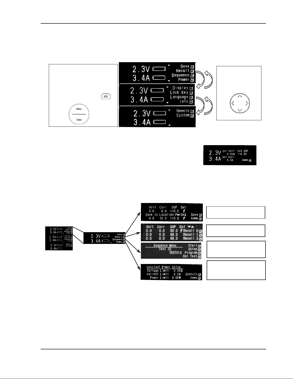
Calibration and Verification Sorensen SGI Series
SEQUENCE See
Sections 3.7.6 for submenus
and 3.8.4 for details.
POWER - See
Sections 3.7.8 for next
screens and 3.8.5 for details.
SAVE - See Section 3.8.2 for
details.
RECALL - See Section 3.8.2
for details.
NavPad
Toggle between pages
by pressing up or down
on the NavPad. See
Section 3.5.
Page 1
Page 2
Page 3
Home Menu is made up of three
pages from which the user may
navigate to the various function or
command screens.
Return to Home Menu Page 1 by
pressing Escape as needed,
or Menu, except as noted
in Section 3.5
3.7 Menu Map
3.7.1 Home Menu
3.7.2 Default Programming Menu
Access this menu directly with the hard-code keys,
Voltage, Current, or Overvoltage, on the Control Panel.
See Section 3.8.1 for details.
3.7.3 Navigating from Home Menu Page 1
3-18 M550221-01 Rev AA
Page 71
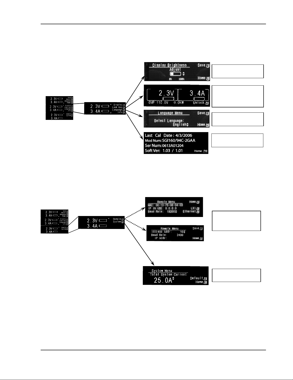
Sorensen SGI Series Calibration and Verification
DISPLAY - See
Section 3.8.7 for details.
LOCK KEY - See
Sections 3.7.12 for next
screen, and 3.8.8 for
details.
LANGUAGE - See
Section 3.8.9 for details.
INFO - See
Section 3.8.10 for details.
Ethernet Remote Menu
REMOTE - See
Section 3.7.9 for
submenus and Section
SYSTEM - See
Section 3.8.12 for details.
GPIB Remote Menu
or
3.7.4 Navigating from Home Menu Page 2
3.7.5 Navigating from Home Menu Page 3
M550221-01 Rev AA 3-19
Page 72
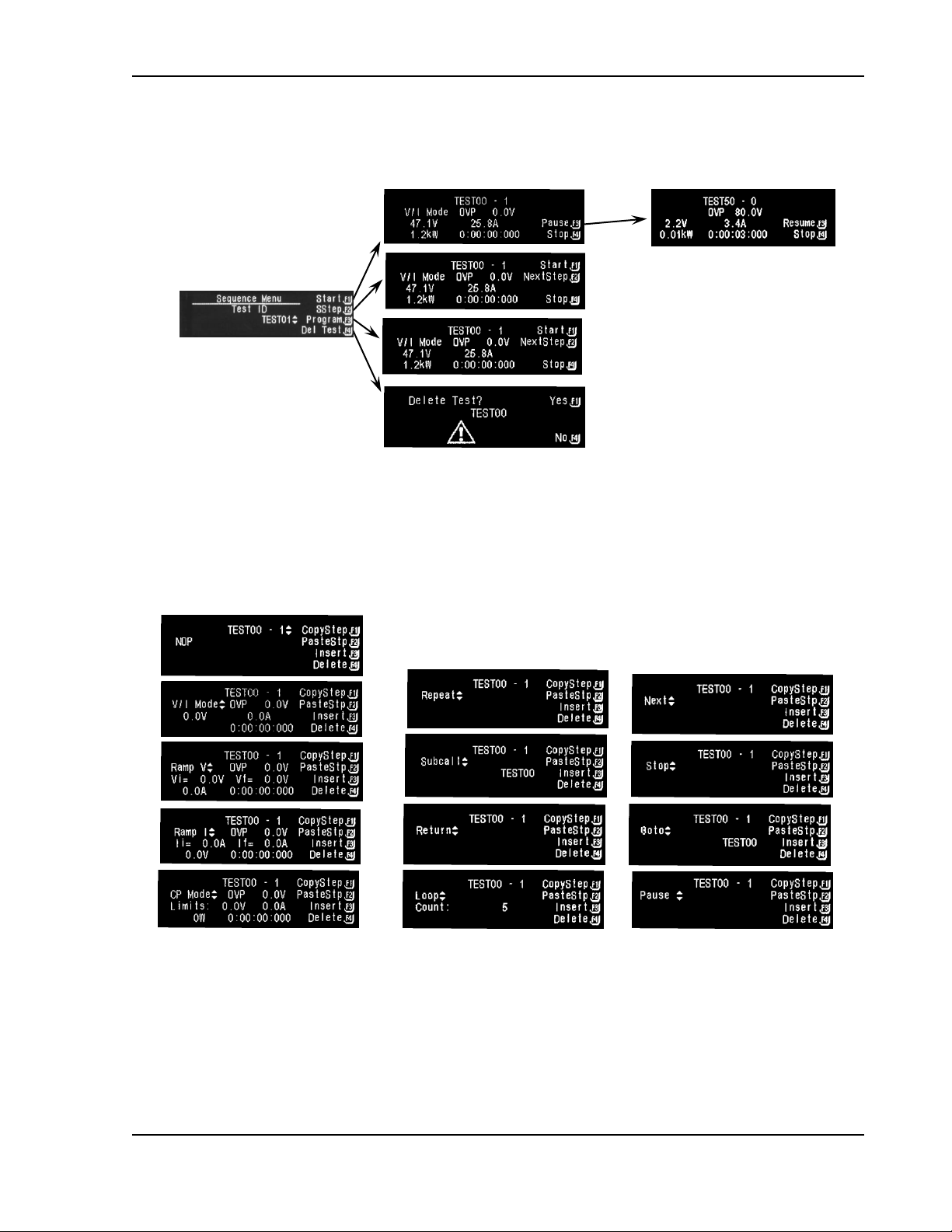
Calibration and Verification Sorensen SGI Series
3.7.6 Sequence Menu
Refer to Basic Sequence Operation under Section 3.8.4.
3.7.7 Sequence Programming Operation
The screens in this section show the various operations available for
programming a sequence. See details on Step Operations under
Section 3.8.4.
3-20 M550221-01 Rev AA
Page 73

Sorensen SGI Series Calibration and Verification
3.7.8 Constant-Power Setup Menu
See Section 3.8.5 for details.
3.7.9 Remote Menu
Remote menu is either GPIB or Ethernet option. The submenus for Ethernet
are mapped here; there are no submenus for the GPIB Remote screen (see
Section 3.8.11 for details).
ETHERNET
The Ethernet Remote Menu provides submenus for Save (F2), LXI
Settings (F3) and Ethernet Menu (F4). The Ethernet Menu provides
submenus for Server Port (F3) and Static IP Configuration (F4). See
Section 3.8.11 for details.
M550221-01 Rev AA 3-21
Page 74
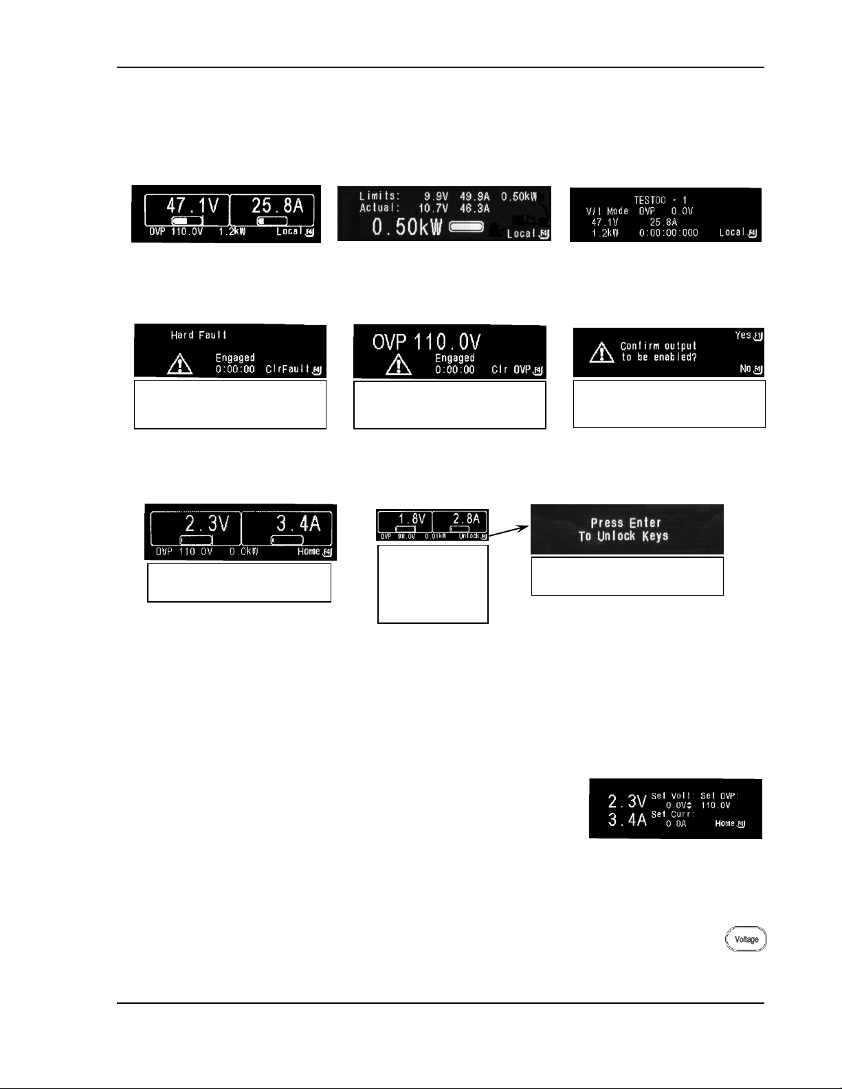
Calibration and Verification Sorensen SGI Series
General hardware failure has
occurred. Press F4, Clear Fault,
to reset the unit.
Overvoltage Protection was
tripped. Press F4, Clear OVP;
the unit will reset in 4 seconds.
Displays when a saved setting
with Output On is recalled. See
Section 3.8.3 for details.
Home Menu Time Out Screen
displays after 30-second idle.
Screen to confirm Unlock control
panel keys.
Locked Key
Screen (From
Home Menu
Page 2, F2) to
unlock press F4
3.7.10 Remote Control Screen Examples
Remote screens display when operation is controlled by computer. Pressing
F4 from any Remote screen returns operation to Local Mode.
3.7.11 Warning Screens
3.7.12 Other Screens
3.8 Programming/Operating Functions
This section describes various programming/operating instructions
3.8.1 Voltage, Current, and Overvoltage Protection Programming
Press Voltage, Current, or Overvoltage key on Control Panel
to go directly to the Default Programming Menu. The editing
arrow will be displayed next to the corresponding item
pressed.
3-22 M550221-01 Rev AA
PROGRAMMING VOLTAGE
Go directly to Voltage programming by pressing the voltage key. The
Default Programming menu is displayed and the Editing Arrow is to the
right of the "Set Volt" editable value. Edit the value by NavPad up/down
Page 75
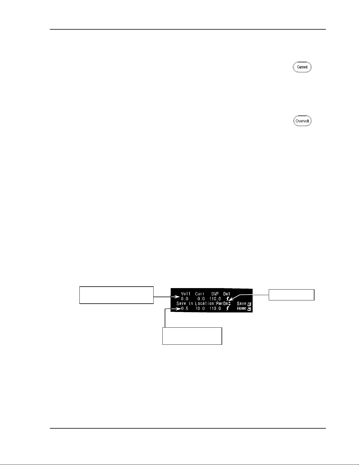
Sorensen SGI Series Calibration and Verification
Values pulled in from Default
Programming Menu.
Save to location.
Values currently saved
in location.
or by entering the value with "Keypad 0-9". For more details see
Section 3.6.
PROGRAMMING CURRENT
Go directly to Current programming by pressing the current key.
The Default Programming menu is displayed and the Editing Arrow is to
the right of the "Set Curr" editable value. Edit the value by NavPad
up/down or by entering the value with "Keypad 0-9". For more details see
Section 3.6.
PROGRAMMING OVERVOLTAGE PROTECTION
Go directly to Overvoltage trip point programming by pressing the
overvoltage key. The Default Programming menu is displayed and the
Editing Arrow is to the right of the "Set OVP" editable value. Edit the
value by NavPad up/down or entering the value with "Keypad 0-9". For
more details see Section 3.6.
3.8.2 Save
There are 11 memory locations (PwrOn, 1 through 9, LAST 0/1) into which a
programmed output configuration of Voltage, Current, OVP (Overvoltage
Protection trip point) and Output Condition can be stored. The LAST 0/1
configuration stores and recovers programmed Voltage, Current, OVP
(Overvoltage Protection trip point), Output Condition, and Foldback Protection
when power supply is turned off. From Home Menu Page 1 press (F1) to enter
the Save menu. Voltage, Current and OVP values programmed in the Default
Programming menu will be pulled into the Save menu, top line, upon reaching
that menu. In addition, the present output condition, output engaged or output
disabled, will be indicated.
M550221-01 Rev AA 3-23
EDIT VOLTAGE, CURRENT AND OVP
Toggle between the editable items using the NavPad and edit Voltage,
Current and OVP to appropriate values (see Section 3.6 for editing
details).
Page 76

Calibration and Verification Sorensen SGI Series
EDIT OUTPUT CONDITION
Pressing NavPad up/down will toggle the output condition indicator on
( ) to indicate the output will be enabled and off (blank) to indicate the
output will be disabled.
Note:
SAVING A CONFIGURATION
With the Editing Arrow adjacent to “Save Location” pressing NavPad
up/down allows the user to scroll through the list of memory locations
(PWR ON, 1-9, LAST 0/1). Using configurations (PWR ON, and 1-9)
Select the appropriate location and press (F3) to save the configuration to
that location. The bottom line of the screen will update with the
configuration information saved. Using configuration (LAST 0/1) press
(F1) to turn ON or (F2) to turn OFF and press (F3) to save configuration.
Press (F4), “Escape” or “Menu” key to exit to the Home Menu Page 1 at
any time.
Note: If setting LAST 1. The EEPROM that stores the Last Programmed
Edits will not take effect until the configuration is saved.
Values(Voltage, Current, OVP, Output State, Foldback Protection) is
limited to 100,000 Write Cycles.
SAVING TO PWR ON
“PWR ON” is a unique “Save Location.” If a configuration is saved to
“PWR ON” location, the next time the ON/OFF front panel switch is
cycled, the SGI unit will power up into the state this configuration was
saved. If the Output Condition was saved as on ( ), which means
power enabled, a warning screen will be displayed at power up. The user
will have 10 seconds to press (F1) and abort the operation. If the count
times out, the supply output terminals will be live and programmed to the
saved configuration values; see Section 3.2 for Output-Enabled Warning.
All other saved configuration locations must be recalled to become active;
see Section 3.8.3.
3.8.3 Recall
There are 10 memory locations (as above, PwrOn and 1-9)
from which a programmed output configuration of Voltage,
Current, OVP (Overvoltage Protection trip point) and Output
Condition can be recalled.
From Home Menu Page 1 press (F2) to enter the Recall
menu. Using the NavPad up/down arrows scroll through the
list of saved configurations. Recall a saved configuration by
pressing the function key (F2-F4) to the right of that
configuration. If a configuration was saved with the Output
3-24 M550221-01 Rev AA
Page 77

Sorensen SGI Series Calibration and Verification
Condition on ( ) and that configuration is recalled, a
warning screen (See Menu Map, Section 3.7.9) will be
displayed *. The user is given the option to press Yes (F1)
to enable or No (F4) to disable the output. All other
settingwill be programmed according to the recalled
configuration regardless of this choice.
*
Note:
The warning screen will not appear if the Output is already enabled.
3.8.4 Sequencing
INTRODUCTION
The SGI sequencing function allows the user to set up the supply to
automatically run a series of voltage, current and power mode operations.
This is especially useful for setting up the supply to test to compliance
standards, or unburdening the test computer in automated testing
applications. Through RS-232, IEEE-488 or Ethernet, an external
computer can trigger the sequences (see SG Series Programming
Manual). Up to 50 sequences may be stored, with each sequence
containing up to 20 individual steps. With the ability to string sequences
together and an extensive list of step functions such as ramping, looping,
goto and subroutine calls, the user can define a nearly infinite variety of
test sequences.
The following sections will assist the user in programming, testing and
running a sequence from the front panel.
BASIC SEQUENCE OPERATION
To access the main Sequencing menu press F3 from
Home Menu Page 1. From here any one of 50
sequences may be selected. The default names for
sequences are TESTxx where xx is a number from
01 to 50. Using SCPI commands via the RS-232,
IEEE-488, or Ethernet interface, the user may
rename these test sequences with meaningful
names of up to 15 characters (see SG Series
Programming Manual).
Note:
DO NOT use non-sequence-related SCPI commands while performing
sequence operations.
Note:
DO NOT use sequence SCPI commands as stand-alone commands
outside a sequence.
M550221-01 Rev AA 3-25
Page 78

Calibration and Verification Sorensen SGI Series
CAUTION!
RESTRICTIONS ON SEQUENCE PROGRAMMING
In order to allow maximum flexibility for generating small incremental
changes during a test sequence, the SGI allows 1 ms time resolution on
each step. With this capability, however, it is possible to create output
changes with fast slew rates, that could generate potentially damaging
large currents, in the output capacitors of the unit; refer to the guideline
note, below.
3-26 M550221-01 Rev AA
Page 79

Sorensen SGI Series Calibration and Verification
Frequency
% V(PK-PK)
10Hz
25%
50Hz
5.0%
100Hz
2.5%
150Hz
1.67%
200Hz
1.25%
Note:
When creating test sequences, use the following guidelines to prevent damage
to the unit:
Estimate the AC frequency and peak-to-peak voltage, V(PK-PK) of
the desired test sequence.
Convert the estimated V(PK-PK) to a % of maximum output
voltage (e.g., if V(PK-PK) is 10V and maximum voltage of the
supply is 100V, then %V(PK-PK) = 10%)
Verify that the frequency and %V(PK-PK) do not exceed the
values below:
Another consideration is the actual rise and fall capabilities of the
output of the supply. Although damage will not occur, the shape of
the output waveform will be affected by the rise/fall times in
relation to programmed sequence settings. These vary widely
depending on the load conditions; contact the factory for further
information.
.
Note:
Contact the factory for detailed information if the desired waveform
exceeds the recommended limits as discussed.
To change the test sequence, use the NavPad up/down to scroll through the
test list. From this menu the user may Start (F1), Single Step (F2), Program
(F3) or Delete (F4) a sequence.
START: press F1 from the main Sequence Menu to start and run a test
sequence. The display will show the test sequence name and step number
(e.g., TEST01-12, Sequence TEST01, step 12). It will also indicate the current
operation being executed (see Section 3.8.4.3, Operations) and will display
voltage, current, OVP, power and time remaining for that step. The time
format is hhhh:mm:ss:sss (last three digits are milliseconds).
User may pause or stop the test at any time by pressing either F3 to pause or
F4 to stop the sequence. The output will pause or stop in the same state as
the test step was when the key was pressed. Pressing F3 (Resume) restarts
the sequence from the beginning of the same step. (
Note:
For steps with
voltage or current ramps, the step will resume at the beginning of the ramp and
not at the point at which the ramp was paused.) Pressing F4 (Stop) to stop the
sequence returns the display to the main Sequence Menu.
SINGLE STEP: press F2 from the main Sequence Menu to single step
through a test sequence. The display will show the test sequence name and
M550221-01 Rev AA 3-27
Page 80

Calibration and Verification Sorensen SGI Series
step number. It will also indicate the current operation being executed and
display voltage, current, OVP, power and time remaining for that step.
User may start the sequence after any step causing it to run in continuous
mode, by pressing F1 (Start). The sequence will start from the beginning of the
test sequence, not the beginning of the current step. To continue to single step
through each sequence step, press F2 (NextStep). Pressing F2 NextStep
before the timer ends, will replay the step. Pressing F4 (Stop) allows the user
to stop the single step mode, and the display returns to the main Sequence
Menu.
PROGRAM: press F3 from the main Sequence Menu to program a test
sequence. The Test Sequence submenu shows the name of the current test
sequence and step number. In addition it displays the primary operation of the
test step (there are 13 different operations, see Section 3.8.4.3, Operations).
From this submenu the user may copy (F1), paste (F2), insert (F3) or delete
(F4) a test step.
CopyStep (F1): copies the current step characteristics into a buffer for
later recall using the PasteStp (F2) function.
PasteStp (F2): pastes the current characteristics from the copy buffer
into the existing test step.
Insert (F3): inserts a new step before the currently displayed test step.
The default operation in the new step is set to NOP.
Delete (F4): deletes the current test step from the test sequence, and
inserts NOP into step 20 of the sequence.
DEL TEST: press F4 from the main Sequence Menu to
delete the entire currently selected test sequence. If Del
Test is selected, a warning screen will appear prompting the
user to either confirm (Yes – F1) or cancel (No – F4) the
delete action. Deleting a test actually fills each test step in
the sequence with a NOP (see Section 3.8.4.3)., and fills
Step 21 with STOP operation.
STEP OPERATIONS
When programming a test sequence (see Section 3.8.4.2) each step
operation can be any one of thirteen different functions. To access those
functions, from Home Menu Page 1 press F3 (see Menu Map,
Sections 3.7.2, 3.7.5, and 3.7.6), and use the NavPad to scroll through
the various step operations (see Section 3.5, Navigation) while in the
Sequence Step Programming submenu.
1. Once an operation has been selected for the present step, navigate to the
editable items and input values for each setting as appropriate (see
Section 3.6, Editing).
3-28 M550221-01 Rev AA
Page 81

Sorensen SGI Series Calibration and Verification
2. After programming a step, navigate to the step-number location on the screen
and scroll to the next step number to be programmed.
3. Once at the next step number to be programmed, start again by choosing an
operation for that step and continue as described above.
4. At the end of the sequence or to abort the sequence, press either the Escape
key or Menu to jump to the Save screen. F1 (Yes) saves the sequence (in
non-volatile memory) and returns to main Sequence Menu. F4 (No) will
retain the current changes only until the power supply is turned off. The next
power on restores the sequence to its previous condition.
The following are descriptions for each sequence operation:
NOP, No Operation: Used as a placeholder in the test
sequence, no values are changed during this step, and it
does not add time to the sequence.
V/I Mode, Voltage/Current Mode: This operation sets
the voltage, current and OVP to the programmed values
for the set period of time during the sequence step.
Navigate to each editable item to input values for Voltage,
Current, Overvoltage Protection and duration.
Ramp V, Ramp Voltage: This operation allows the user
to ramp the output voltage from an initial, or start, value
(Vi) to a final, or stop, value (Vf) over the time period
specified. Internally the unit uses Vi, Vf and the time to
calculate an appropriate ramp function to drive the output
during the test step. Use the NavPad to set the OVP,
initial Voltage (Vi), final Voltage (Vf), Current limit, and
duration.
Ramp I, Ramp Current: This operation allows the user
to ramp the output current from an initial, or start, value
(Ii) to a final, or stop, value (If) over the time period
specified. Use the NavPad to set the OVP, initial Current
(Ii), final Current (If), Voltage limit, and duration.
CP Mode, Constant-Power Mode: This operation is
similar to the V/I Mode, except it sets the supply in a
constant-power mode (See Section 3.8.5). Use the
NavPad to input values for OVP, Voltage limit, Current
limit, Constant Power setting and duration.
M550221-01 Rev AA 3-29
Page 82

Calibration and Verification Sorensen SGI Series
Repeat: This operation returns to the beginning of the
test cycle (this could be a prior test sequence or the
beginning of the current test sequence, depending on the
number of branches and subcalls used in the affected
sequences) and repeats all previously executed steps a
single time. Once executed, the sequence continues to
execute all remaining steps after the Repeat command.
To repeat the preceding steps more than once, use the
Loop operation.
Subcall: This operation calls another test that runs as a
sub-sequence. If that sub-sequence includes a Return
command, execution of the primary sequence resumes at
the step following the Subcall step. Use the NavPad to
scroll to the desired Test name and change as
appropriate.
Return: This operation causes execution to resume at
the step immediately following the most recent Subcall.
When occurring in a primary sequence, without a prior
Subcall, Return stops execution of the test sequence.
Return is one of only three operations that may be used
in step 21 of a test sequence.
Loop: This operation causes the unit to repeat all steps
between the Loop operation and the Next operation for
the specified number of counts (maximum of 65,535).
Use the NavPad to set the Count for the total number of
loops.
Use the Next operation after the last step to be repeated.
Once the Loop has completed the set number of counts,
the unit will continue to execute the remainder of the
sequence.
Next: Next is used at the end of a Loop to signify the end
of the looped sequence.
If Next is not preceded by the Loop operation, this is an
INVALID condition. If the program encounters the Next
command under these conditions, the sequence will abort
and the output power to the terminals will be disabled.
Stop: Stops the test sequence execution and retains the
last programmed output value. The Stop operation may
be used in step 21 of a sequence.
Goto: This operation allows the sequence to exit the
existing test sequence and begin another test sequence.
Goto is used to string together multiple sequences for a
single test. The Goto operation may be used in step 21 of
a sequence.
Pause: This operation suspends execution of the
sequence and waits for operator input to press either the
3-30 M550221-01 Rev AA
Page 83
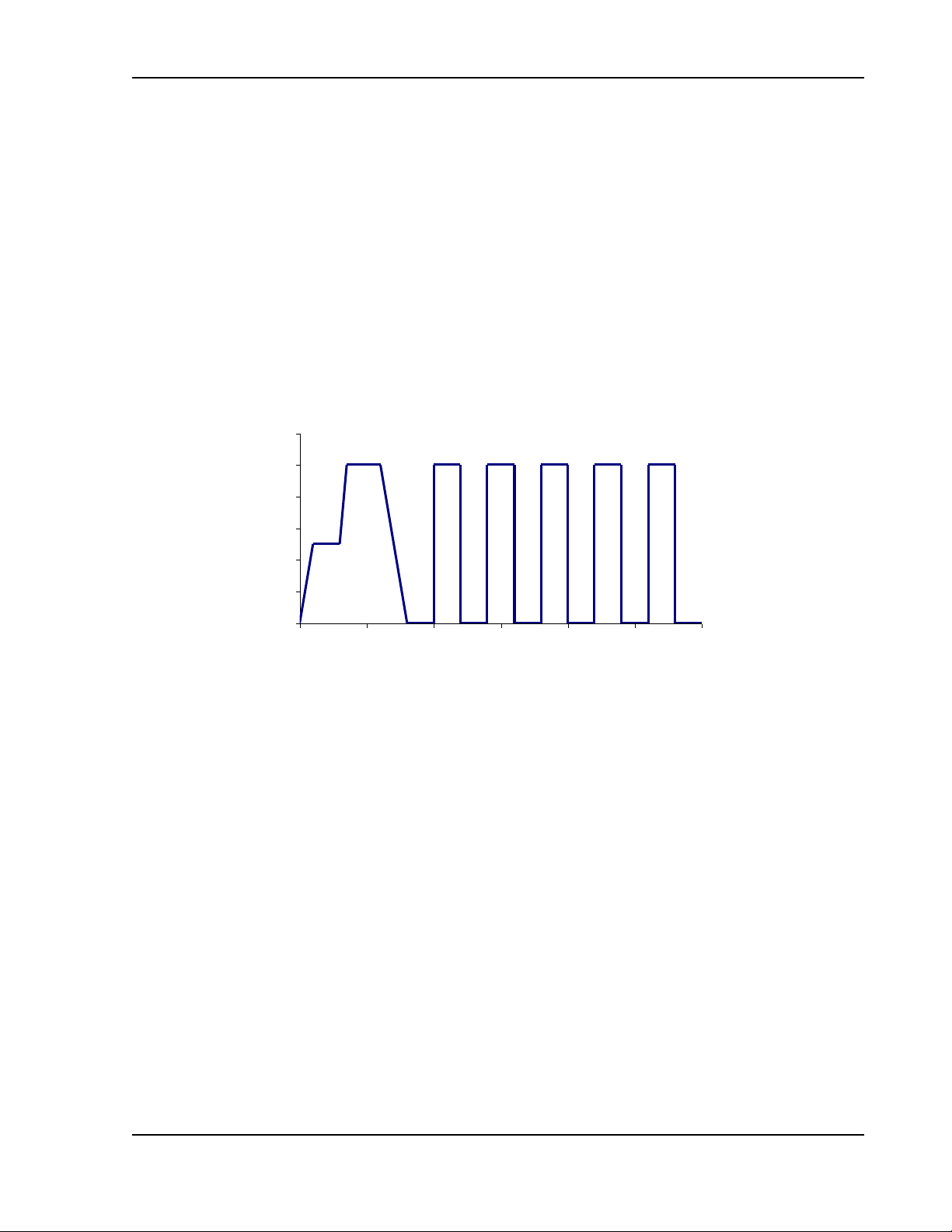
Sorensen SGI Series Calibration and Verification
Burn-in Sequence
0 5 10 15 20 25 30
Time in seconds
Output Voltage
Resume key to continue the sequence or the Stop key to
end the sequence.
SEQUENCING EXAMPLE
The following provides an example of programming and running a test
sequence.
A typical burn-in sequence requires the voltage to the device-under-test
(DUT) to ramp up to a nominal voltage, allow the unit to soak at that voltage
for a period of time, then ‘bump’ up that voltage to another level, soak, etc.,
then return the output back to zero. In some cases, an on/off power cycle
sequence may also be required. Figure 3-11 provides a graphical
representation of this example burn-in sequence.
Figure 3-11. Burn-in Sequence Example
To begin programming a sequence it is important to know the exact settings for
each step of the sequence. In this case, two sequences will be programmed:
the first being the up/down ramp sequence, and the second the on/off
sequence. The two will be strung together using a Goto command.
The example sequence will perform the following:
Sequence 1 – Up/Down Ramp
Step 1 – Ramp the output voltage from 0 V to 20 V over a 1 s period
Step 2 – Hold the voltage at 20 V for 2 s
Step 3 – Ramp the voltage from 20 V to 40 V over a 500 ms period
Step 4 – Hold the voltage at 40 V for 2.5 s
Step 5 – Ramp the voltage from 40 V to 0 V over a 2 s period
Step 6 – Hold the voltage at 0 V for 2 s
Step 7 – Go to sequence 2
M550221-01 Rev AA 3-31
Page 84

Calibration and Verification Sorensen SGI Series
Sequence 2 – On/Off Loop
Step 1 – Begin a loop and set the count to 5
Step 2 – Turn on the voltage to 40 V for 2 s
Step 3 – Turn off the voltage for 2 s
Step 4 – Execute the Next loop until all 5 are complete
Step 5 – Stop the sequence
Run the sequence.
To program these sequences, do the following:
Sequence 1 – Up/Down Ramp
From the Home Menu Page 1, select F3 to enter the main Sequence
Menu. Use the NavPad up/down to select the sequence (Test ID) labeled
TEST01. Press F4 (Del Test) to reset all steps in TEST01 to a NOP
condition. This establishes a known state for this sequence. Press F3 to
enter the Sequence Step menu.
Step 1 – Ramp the output voltage from 0 V to 20 V over a 1 s period
From the Sequence Step menu, use the NavPad to set the test step to
the first step, TEST01-1. Use the NavPad to set the operation to
Ramp V mode. Set OVP to an appropriately high level (60 V for this
example), Vi to 0 V, Vf to 20 V and current to a nominal 10 A (for this
example we assume there is no load – or a very light load –
connected to the output). Set the time duration to 1 s or (0:00:01:000).
Once these values are set, press the F1 key to copy this setup into
the copy buffer for later use.
Step 2 – Hold the voltage at 20 V for 2 s
Use the NavPad to change to the next step (TEST01-2). Select the
V/I Mode operation and set the OVP to 60 V, voltage to 20 V, current
to 10 A and time duration to 2 s.
Step 3 – Ramp the voltage from 20 V to 40 V over a 500 ms period
Use the NavPad to change to the next step (TEST01-3). Use the F2
key to paste in a copy of the previously saved Ramp V step. Make
changes to this step by changing Vi to 20 V, Vf to 40 V and the time
duration to 500 ms (0:00:00:500)
Step 4 – Hold the voltage at 40 V for 2.5 s
Use the NavPad to change to the next step (TEST01-4). Select the
V/I Mode operation and set the OVP to 60 V, voltage to 40 V, current
to 10 A and time duration to 2.5 s.
Step 5 – Ramp the voltage from 40 V to 0 V over a 2 s period
Use the NavPad to change to the next step (TEST01-5). Use the F2
key to paste in a copy of the previously saved Ramp V step. Make
changes to this step by changing Vi to 40 V, Vf to 0 V and the time
duration to 2 s.
Step 6 – Hold the voltage at 0 V for 2 s
3-32 M550221-01 Rev AA
Page 85

Sorensen SGI Series Calibration and Verification
Use the NavPad to change to the next step (TEST01-6). Select the V/I
Mode operation and set the OVP to 60 V, voltage to 0 V, current to 10
A and time duration to 2 s.
Step 7 – Go to sequence 2
Use the NavPad to change to the next step (TEST01-7). Select the
Goto operation and set the next step to TEST02. Press the ESC or
Menu key to move to the Save Sequence screen and press F1 for Yes.
Sequence 2 – On/Off Loop
From the Home Menu Page 1, select F3 to enter the main Sequence
Menu. Use the Navigation arrows to select the sequence labeled TEST02.
Press F4 (Del Test) to reset all steps in TEST02 to a NOP condition.
Press F3 to enter the Sequence Step menu.
Step 1 – Begin a loop and set the count to 5
Use the NavPad to change to the first step (TEST02-1). Select the
Loop operation and set the count to 5.
Step 2 – Turn on the voltage to 40 V for 2 s
Use the NavPad to change to the next step (TEST02-2). Select the V/I
Mode operation and set the OVP to 60 V, voltage to 40 V, current to
10A and time duration to 2 s. Press F1 to copy this step to the copy
buffer.
Step 3 – Turn off the voltage for 2 seconds
Use the NavPad to change to the next step (TEST02-3). Press the F2
key to paste the previously saved step into this step. Set the voltage
to 0 V, all other settings remain the same.
Step 4 – Execute the Next loop until all 5 are complete
Use the NavPad to change to the next step (TEST02-4). Select the
Next operation.
Step 5 – Stop the sequence
Use the NavPad to change to the next step (TEST02-5). Select the
Stop operation. Press the ESC or Menu key to move to the Save
Sequence screen and press F1 for Yes.
This completes programming of the sequences.
To run this sequence, from Home Menu Page 1, press F3 to enter the main
Sequence menu. Select TEST01 test sequence and press F1 to start the
sequence. The display will show progress of the sequence and should
complete in approximately 30 s.
M550221-01 Rev AA 3-33
Page 86
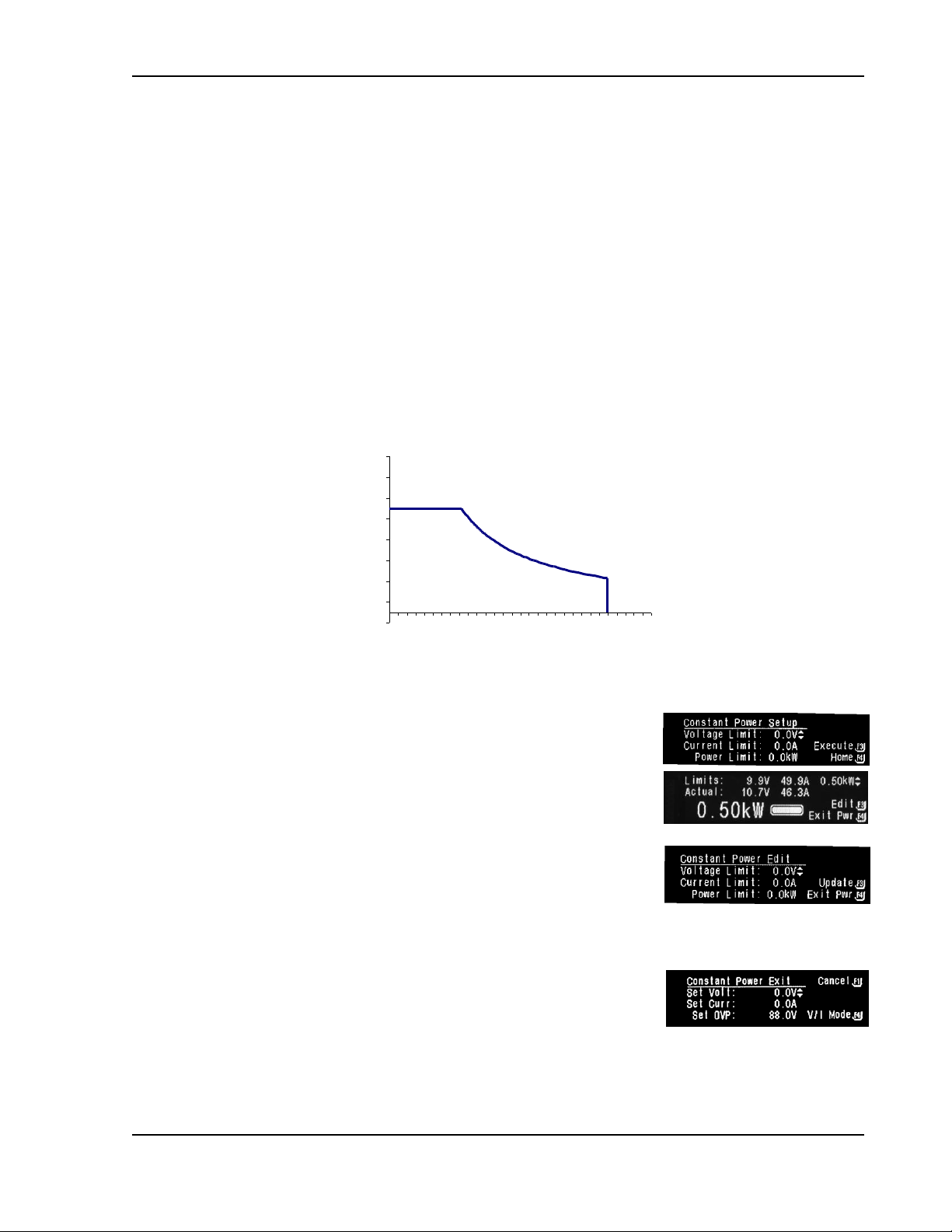
Calibration and Verification Sorensen SGI Series
Constant Power Mode
Current
Voltage
V limit
I limit
Constant Power setting
3.8.5 Constant-Power Mode
The Constant-Power Mode allows the supply to regulate the output to a
constant power setting as opposed to the more common constant voltage or
constant current modes of operation (see Section 3.2). (
intended primarily for loads with response times greater than approximately
10 ms). While in this mode, the supply will continually adjust the voltage and
current levels to attempt to maintain a constant power to the load. In order to
provide additional protection for the load, voltage, and current limits may be set
while in the Constant-Power mode. If the unit cannot regulate to the Constant
Power setting due to load conditions, it will regulate either at the voltage or
current limit depending on the load demand. See Figure 3-12.
Note:
This mode is
Figure 3-12. Constant-Power Example
To access the Constant Power Setup menu, press the F4
key from Home Menu Page 1. Navigate to each editable
item and enter the appropriate values. Press F3 to
execute (the display jumps to Constant Power screen) or
F4 to abort (the display returns to Home Menu Page 1).
From Constant Power screen, the user may either edit the
limits again or exit Power mode. F3 jumps to Constant
Power Edit screen, and after inputting new values, press
F3 to make those changes effective and jump back to
Constant Power Screen, or press F4 to ignore the
changes and jump to Constant Power Exit.
From Constant Power Exit, F1 cancels the command to exit
and jumps back to Constant Power screen, or F4 exits
Constant Power and jumps to Home Menu Page 1 with the
Voltage, Current, and OVP values as set. (See Menu Map,
Section 3.7.8).
3-34 M550221-01 Rev AA
Page 87

Sorensen SGI Series Calibration and Verification
3.8.6 Home Timeout
The display jumps to this screen when the system has been
idle for 30 seconds. Press Escape or F4 to return to Home
Menu Page 1.
3.8.7 Display Brightness
Navigate from Home Menu Page 2, F1; use NavPad to dim
or increase the brightness. F1 saves the adjusted setting for
the remainder of the session and for future power-ups. F4
maintains the setting for the remainder of the session and
returns the brightness to its previously saved level at next
power-up.
3.8.8 Lock Key
To prevent changes due to accidental pressing of the keys,
Lock the keys from Home Menu Page 2, F2. This screen
appears until F4 is pressed; a confirmation screen will
appear with instructions to press Enter to unlock keys (see
Section 3.7.12, Other Screens) before returning to Home
Menu.
NOTE:
or Constant-Current modes.
Lock Key only works while in the Constant-Voltage
3.8.9 Language
The Language submenu allows the user to change the
default language for the menu selections. To select this
menu, from Home Menu Page 2 press F3 to go to the
Language Menu and select a language to work in. Pressing
F1 will save the selection and exit the Language Menu. The
next time the unit is powered up it will be in the last saved
language. Pressing F4 will keep the selected language only
for the remainder of the session and will revert to the
previously saved language at next power-up.
FOREIGN LANGUAGE
If the unit is set to a language foreign to the user, press the
escape key until Home Menu Page 1 appears. (Even in a
foreign language, the Voltage and Current values will still
display: value with the letter V and value with the letter A,
respectively. Also, there will be only one inter-screen
navigation arrow, which is located at the bottom of the
M550221-01 Rev AA 3-35
Page 88

Calibration and Verification Sorensen SGI Series
screen). Use the NavPad to scroll down to Home Menu
Page 2 (there will be two inter-screen navigation arrows,
one at the top and one at the bottom of the screen). Press
F3, which jumps to the Language Menu, and then use the
NavPad to scroll to the user's native language.
3.8.10 Info
The Supply Information screen shows the date that the unit
was last calibrated, Model Number and Serial Number of the
unit, and version of the software. To access this screen,
from Home Menu Page 2 press F4.
3.8.11 Remote
Remote, F1, provides screens for either the Ethernet option
or the GPIB option, described in the following subsections.
ETHERNET
The Ethernet Remote Menu displays the Ethernet MAC
address of the power supply, which cannot be edited.
Access the menu from Home Menu Page 3, F1 key. This
menu also displays in the IP IN USE: line, the IP address
presently in use from either a static IP setting or from the
DHCP server, depending on how assigned. The Baud Rate
is editable via the NavPad; changing it here changes the
rear panel RS-232 SCPI baud rate. Pressing the F2 key will
save the set baud rate. The initial factory setting is 19200.
LXI
The LXI submenu (F3 from the Remote Menu) displays
two settings required by the LXI requirements.
PING Response: enables or disables the power supply’s
response to a ping packet sent from a remote Ethernet host. To
change the setting to either ENABLED or DISABLED, move the
editing arrows to the PING Response: line by pressing NavPad
left/right, and then change the setting by pressing NavPad
up/down. Press F1 to Cancel the change and return to the
Remote Menu screen, or press F4 to Save the changed setting.
Identification: controls the LAN LED on the power supply’s
rear panel. ENABLED causes the LAN LED to flash for visual
identification. DISABLED causes the LAN LED to be steady-lit
to indicated the power supply’s connected status. To change
the setting, move the editing arrows to the Identification field by
3-36 M550221-01 Rev AA
Page 89

Sorensen SGI Series Calibration and Verification
pressing NavPad left/right, and then change the setting by
pressing NavPad up/down. Press F1 to Cancel the change and
return to the Remote Menu screen, or press F4 to Save the
changed setting.
ETHERNET
The Ethernet submenu (F4 from the Remote Menu) displays
the Primary (Pri Config) and Secondary (Sec Config)
Ethernet configurations, both of which are editable. It also
provides further submenus to change the Server Listener
Port (F3) and the Static IP address (F4).
The Primary configuration is attempted at power-up, and if it fails, the system
defaults to the Secondary configuration. However, both setting “DHCPacquired” and selecting “Auto IP Enabled” together in the Primary
configuration, prevents the power supply from trying the Secondary
configuration.
Useful configurations are described as follows:
Pri Config: STATIC IP
Sec Config: DHCP
At power-up the power supply will assign itself the configured static IP address.
If no other device is using the IP address, the power supply continues with that
static IP address. If some other device is using that address, the power supply
will move to Secondary and attempt to acquire an IP address from a DHCP
server repeatedly until it gets an address.
Pri Config: STATIC
Sec Config: DHCP+AUTOIP
At power-up the power supply will assign itself the static IP address. If no
other device is using the IP address, the power supply continues with that
static IP address. If some other device is using that address, the power supply
will move to secondary and attempt to acquire an IP address from a DHCP
server. If it cannot find a DHCP server to assign an address, it will assign itself
a link-local address. If no other device is using that link-local address it will use
it for 5 minutes minimum. At that time, if it is already in communication with
some other device, it will hold onto that link-local address until the
communication is finished and then retry DHCP. Then, if DHCP is not
available, the power supply will revert to the last successful link-local address
for another 5 minutes minimum.
Pri Config: DHCP
Sec Config: STATIC
At power-up the power supply will attempt to acquire an IP address from a
DHCP server. If it cannot find a DHCP server to assign an address, the power
supply will move to Secondary and assign itself the static IP address. If no
other device is using the IP address, the power supply continues with that
static IP address. If some other device is using the static IP address, the power
supply will move back to Primary and start the entire operation again.
Pri Config: DHCP+AUTOIP
Sec Config: will not be used with the Pri Config, above
M550221-01 Rev AA 3-37
Page 90
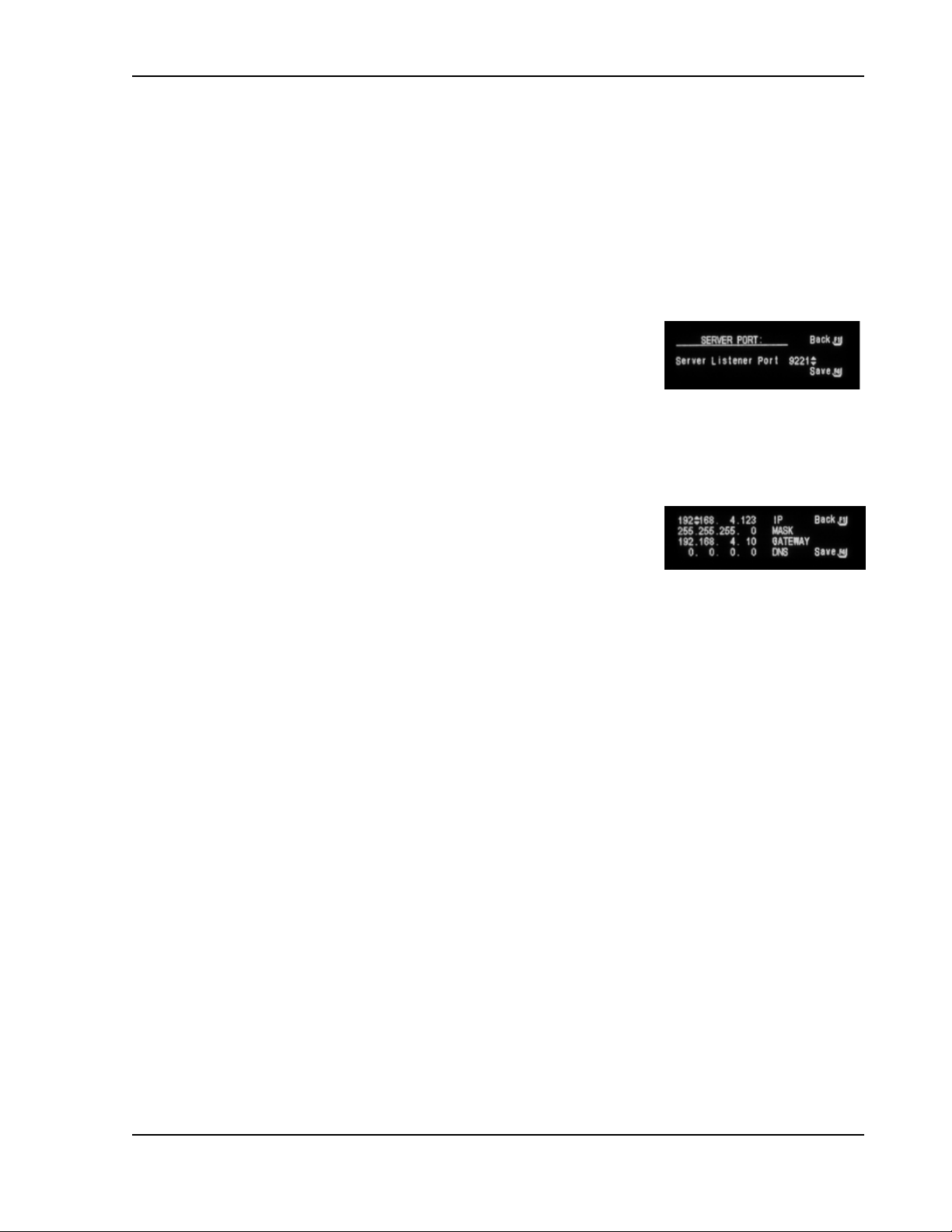
Calibration and Verification Sorensen SGI Series
At power-up the power supply will attempt to acquire an IP address from a
DHCP server. If it cannot find a DHCP server to assign an address, it will
assign itself a link-local address. If no other device is using that link-local
address, it will use it for 5 minutes minimum. At that time, if it is already in
communication with some other device, it will hold onto the link-local address
until the communication is finished and then retry DHCP. If DHCP is not
available, the power supply will revert to the last successful link-local address
for another 5 minutes minimum.
PORT
The Server Port Menu is used to set the network TCP/IP
socket listening port. Valid values are 1025 to 65535. The
factory default setting is 9221. To change, press NavPad
up/down or use the numeric keys to enter specific values.
Press F4 to save the change or press F1 to return to the
Ethernet menu without changing anything.
STATIC IP CONFIGURATION
The Static IP menu allows manual setting not only of the IP
address, but also subnet mask, gateway and Domain
Name Server (DNS) server. The four IP octets in each field
are edited one at a time. Navigate to each octet by
pressing NavPad left/right, then change the value by either
pressing NavPad up/down or by entering a specific value
with the numeric keys.
IP: input any standard IP address. (Factory setting is 192.168.0.200). Press F4
to save the changes or press F1 to return to the Ethernet menu without
changing anything.
MASK: input a value that identifies which network segment your power supply
is on, consisting of 4 whole numbers, each ranging from 0 through 255,
separated by periods. (Factory setting is 255.255.255.0, a class-C network
subnet mask). Press F4 to save the change or press F1 to return to the
Ethernet menu without changing anything.
GATE: input the IP Address of any gateway that stands between the
instrument and any other network entities that communicate with the power
supply. (No factory setting). Press F4 to save the change or press F1 to return
to the Ethernet menu without changing anything.
DNS: input an IP address for the Domain Name System (DNS) server. Press
F4 to save the change or press F1 to return to the Ethernet menu without
changing anything.
3-38 M550221-01 Rev AA
Page 91
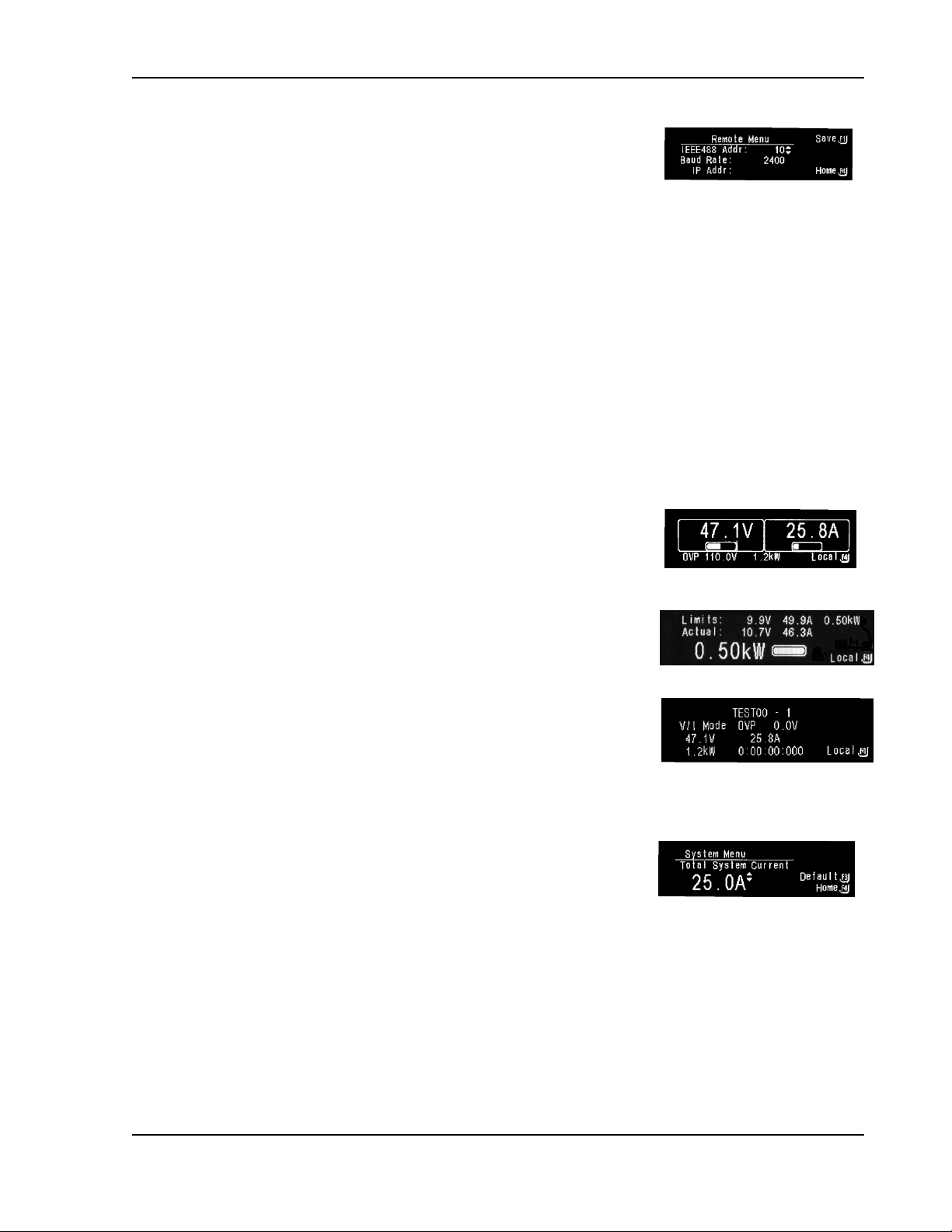
Sorensen SGI Series Calibration and Verification
GPIB AND RS232
Note: For Standard SGI without Ethernet
The Remote Menu for GPIB option or RS232 option
(Home Page 3, F1) allows setting of the GPIB address
and the baud rate for the RS232 interface. Use the
NavPad to set the GPIB address from 1 to 30, and the
RS-232 baud rate from 2400 to 19200. Pressing F1 saves
the new values in non-volatile memory so that they will be
remembered after power down. Pressing F4 keeps the
selected values only until the unit is power down; then, at
next power up, the previously saved settings will be
restored.
REMOTE OPERATION SCREENS
If the unit is being controlled remotely via Ethernet, GPIB or RS-232 interface,
special screens may appear during operation. The following describes those
displays:
Remote Mode Primary display shows the actual values
for Volts and Watts. F4 jumps to Home Timeout
screen.
Remote Mode Power display shows the set points on
the first line, actual values for Voltage and Current on
the second line, and at the bottom, the actual value for
Watts with a bar graph of its percent of full-scale power.
F4 jumps to the Constant Power screen.
Remote Mode Sequence display shows what sequence
is running. F4 jumps to the local Sequence Run
screen.
3.8.12 System
The System submenu allows the user to display the total
system current when the unit is being paralleled with
other SG series supplies.
From Home Menu Page 3, press F2 to enter the System Menu. Determine the
Total System Current by adding the maximum current rating of all supplies in
parallel. Use NavPad or the KeyPad "0-9" to enter the appropriate value. F3
resets Total System Current to the supply default value; F4 keeps the
displayed value and jumps to Home Menu Page 1.
M550221-01 Rev AA 3-39
Page 92

Calibration and Verification Sorensen SGI Series
3.8.13 Warning Screens
There are two warning screens that may appear during the course of
operation:
HARD FAULT
Hard Fault warns that a hardware fault has occurred in a power module, such
as an overtemperature, undervoltage of AC input, or converter failure. These
conditions might clear themselves, however, if they continue to occur after
pressing the F4 (ClrFault) key, contact the factory for service assistance.
OVP FAULT
OVP Fault occurs when the output voltage of the supply exceeds the OVP
setting. When this occurs the output is disabled, and voltage and current
output go to 0. To clear the display, press F1 (Clr OVP). The display will
return to Home Menu Page 1, and the output will remain disabled.
Note:
re-enabling the output.
It is important to correct the condition that caused the OVP, prior to
3.9 Remote Analog Control Connector (J1)
The Analog Control connector of the Remote Analog Interface on the rear
panel allows the unit to be configured for different operating configurations:
front panel (local) and remote programming of voltage, current, and OVP,
voltage and current monitoring, output enable/disable, etc. Refer to Figure
3-13 for the connector pin-out diagram. The setup and operating requirements
of each configuration are provided in Sections 3.10 through 3.13.3.
The SGI also has the capability of providing summing of remote analog input
with the set values on the front panel (or programmed values via the digital
interface) for voltage, current and OVP. This capability provides a means to
modulate a set value with the signal on the voltage, current and OVP analog
input. If the user only desires to control the unit with the analog input, all the
front panel values (V/I/OVP) or digital settings should be set to zero.
3-40 M550221-01 Rev AA
Page 93

Sorensen SGI Series Calibration and Verification
CAUTION!
If standard, Remote Non-Isolated Analog Interface programming is used, the
programming return (J1-6 and J1-24) is at the same potential as the negative
output terminal of the power supply (not isolated). Proper connection should be
made to signal returns with respect to input programming equipment. Improper
connection might result in ground/return loops and, as a result, internal power
supply damage might occur; output current could then flow by way of the
external connection to the J1 common (J1-6 and J1-24). Refer to Table 3–5.
CAUTION!
The Remote Isolated Analog Interface option is not intended to allow operation
of the power supply at excessive voltages. Operation of Isolated Analog
Interface signals should be at SELV safety voltage conditions to chassis
ground. Refer to Section 1.2.2 for maximum terminal voltages.
REMOTE ANALOG ISOLATED INTERFACE CONTROL (OPTION)
The Remote Isolated Analog Interface control uses the same Analog Control
connector (J1) as the standard interface. This option fully isolates remote
control signals and allows control of units not connected to a common ground.
Control ground is isolated from output power (output negative terminal), which
protects against potential damage from systems with high electrical noise or
large ground loop currents.
Note:
are not available with this option; see Table 3–5 for details.
Some standard, Non-Isolated Analog Interface programming signals
Figure 3-13. Analog Control Connector (J1) Pin-Out
M550221-01 Rev AA 3-41
Page 94
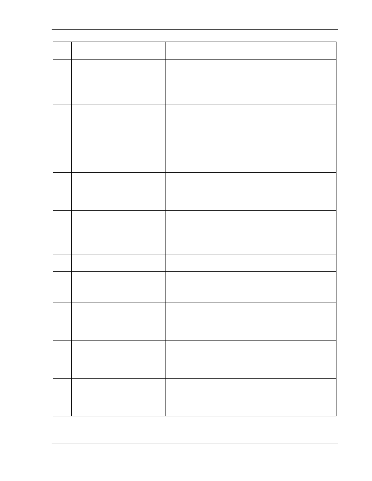
Calibration and Verification Sorensen SGI Series
Pin
Reference
Electrical
Parameters
Functional Description
1
ISO
ON/OFF
Zin ~ 6 k in
series with anode
of opto-isolator
LED
Isolated remote control input for output on/off with an applied
AC/DC voltage source. A positive (+) 6-120 VDC or an AC
input of 12- 240 VAC will enable (turn-on) the output of the
supply. This control input is optically isolated from the output
power negative terminal of the power supply (up to 500 VDC).
Signal return is Pin J1-2 (ISO RTN). See Section 3.13.
2
ISO RTN
—
Isolated signal return for on/off control using Pins J1-1 and
J1-14. Optically isolated from the output power negative
terminal of the power supply (up to 500 VDC).
3
REM OV
SET
Zin ~ 20 k
Control input for remote programming of the overvoltage
protection: 0.25-5.5 VDC = 5-110% of full-scale output
voltage. Reset of an OVP condition is possible by applying
an 10.5-13.3 VDC signal for 7 seconds. Signal return is Pin
J1-6 (COM). Circuit is electrically connected to the output
power negative terminal. See Section 3.12.
4
VP RTN
Zin ~ 10 k
Voltage programming signal return to be used with Pins J1-9,
J1-15 or J1-21; also must be externally connected to Pin J1-6
(COM) signal return when voltage programming is utilized.
Circuit is electrically connected to the output power negative
terminal.
5
ON/OFF
Zin ~ 10 k
pull-up to 15 VDC
Remote control input for output on/off: switch/relay contact
closure or direct short-circuit from this terminal to Pin J1-6
(COM) signal return will enable (turn-on) the output of the
supply; remote circuit must sink up to 1.5 mA from 15 VDC to
enable. Circuit is electrically connected to the output power
negative terminal. See Section 3.13.
6
COM †
—
Signal return. Internally connected to Pin J1-24. Circuit is
electrically connected to the output power negative terminal.
7
I MON
Zout ~ 100
Monitor signal for output current: 0-10 VDC = 0-100% of fullscale output current. Minimum recommended load resistance
is 100 kCircuit return is Pin J1-6 (COM). Circuit is
electrically connected to the output power negative terminal.
8
V SET *
Zout ~ 100
Monitor signal for front panel voltage potentiometer setpoint:
0-5 VDC = 0-100% of full-scale setpoint. Minimum
recommended load resistance is 100 k Signal return is Pin
J1-6 (COM). Circuit is electrically connected to the output
power negative terminal.
9
VP 5V
Zin ~ 10 k
Control input for remote voltage programming using a voltage
source: 0-5 VDC = 0-100% of full-scale output voltage. Do
not exceed an input of 13.3 VDC. Signal return is Pin J1-4 or
Pin J1-20 (VP RTN). Circuit is electrically connected to the
output power negative terminal. See Section 3.11.
10
IP 5V
Zin ~ 10 k
Remote control input for current programming using a voltage
source: 0-5 VDC = 0-100% of full-scale output current. Do not
exceed an input of 13.3 VDC. Signal return is Pin J1-23 or
Pin J1-25 (IP RTN). Circuit is electrically connected to the
output power negative terminal. See Section 3.10.
3-42 M550221-01 Rev AA
Page 95

Sorensen SGI Series Calibration and Verification
Pin
Reference
Electrical
Parameters
Functional Description
11
ISET *
Zout ~ 100
Monitor signal for front panel current potentiometer setpoint:
0-5 VDC = 0-100% of full-scale setpoint. Minimum
recommended load resistance is 100 k Signal return is Pin
J1-6 (COM). Circuit is electrically connected to the output
power negative terminal.
12
Not Used
13
14
ISO
TTL/CMOS
Zin ~ 900in
series with anode
of opto-isolator
LED
Isolated remote control input for output on/off with a logic
signal: a logic-high, 5 VDC TTL/CMOS signal will enable
(turn-on) the output of the supply, and a logic-low signal
disables (turns off) the output. This control input is optically
isolated from the output power negative terminal of the power
supply (up to 500 VDC). Signal return is Pin J1-2 (ISO RTN).
See Section 3.13.
15
VP 10V
Zin ~ 20 k
Remote control input for voltage programming using a voltage
source: 0-10 VDC = 0-100% of full-scale output voltage. Do
not exceed an input of 25 VDC. Signal return is Pin J1-4 or
Pin J1-20 (VP RTN). Circuit is electrically connected to the
output power negative terminal. See Section 3.11.
16
IP 10V
Zin ~ 20 k
Remote control input for current programming using a voltage
source: 0-10 VDC = 0-100% of full-scale output current. Do
not exceed an input of 25 VDC. Signal return is Pin J1-4 or
Pin J1-20 (VP RTN). Circuit is electrically connected to the
output power negative terminal. See Section 3.10.
17
FAULT
Zout ~ 1 k
Output signal for indicating a fault state: a logic-high state
(approximately +10 VDC) indicates a fault has occurred in a
power module, such as overtemperature, undervoltage of AC
input, or converter failure; front panel Fault LED will also be
lit. Signal return is Pin J1-6 (COM). Circuit is electrically
connected to the output power negative terminal.
18
S/D FAULT
Zout ~ 100
Output signal for shutdown/fault state: a logic-high state
indicates shutdown produced by an OVP condition, PowerOn-Reset (POR), remote disable, or housekeeping supply
fault. An 8 VDC minimum output signal is provided into a
load of 10 kload. Signal return is Pin J1-6 (COM). Circuit is
electrically connected to the output power negative terminal.
See Section 3.13.3.
19
V MON
Zout ~ 100
Monitor signal for output voltage: 0-10 VDC = 0-100% of fullscale output voltage. Minimum recommended load resistance
is 100 kCircuit return Pin J1-6 (COM). Circuit is electrically
connected to the output power negative terminal.
20
VP RTN
Zin ~ 10 k
Voltage programming signal return to be used with Pins J1-9,
J1-15 or J1-21; also must be externally connected to Pin J1-6
(COM) signal return when voltage programming is utilized.
Circuit is electrically connected to the output power negative
terminal.
21
VP RES *
1mA current
source with
compliance
Current source of 1 mA for remote voltage programming
using a resistance connected to signal return Pin J1-4 or
Pin J1-20 (VP RTN): 0-5 kΩ = 0-100% of full-scale output
M550221-01 Rev AA 3-43
Page 96

Calibration and Verification Sorensen SGI Series
Pin
Reference
Electrical
Parameters
Functional Description
voltage of
~ 10.8 V
voltage. Circuit is electrically connected to the output power
negative terminal. See Section 3.11.
22
IP RES *
1mA current
source with
compliance
voltage of
~ 10.8 V
Current source of 1 mA for remote current programming
using a resistance connected to signal return Pin J1-23 or
Pin J1-25 (IP RTN): 0- 5 kΩ = 0-100% of full-scale output
current. Circuit is electrically connected to the output power
negative terminal. See Section 3.10.
23
IP RTN
Zin ~ 10 k
Current programming signal return which is to be used with
Pins J1-10, J1-16 or J1-22; also must be externally
connected to Pin J1-6 (COM) signal return when current
programming is utilized. Circuit is electrically connected to the
output power negative terminal.
24
COM †
—
Signal return. Internally connected to Pin J1-6. Circuit is
electrically connected to the output power negative terminal.
25
IP RTN
Zin ~ 10 k
Current programming signal return which is to be used with
Pins J1-10, J1-16 or J1-22; also must be externally
connected to Pin J1-6 (COM) signal return when current
programming is utilized. Circuit is electrically connected to the
output power negative terminal.
†
With the option, Remote Isolated Analog Interface control, the control signal return is isolated from the
output power negative terminal. See Section Error! Reference source not found. and Section 3.15.
*
Signals not available with the option, Remote Isolated Analog Interface control.
Table 3–5. Analog Control Connector (J1), Designations and Functions
3-44 M550221-01 Rev AA
Page 97

Sorensen SGI Series Calibration and Verification
3.10 Remote Current Programming
Remote current programming is summed with the front panel or digital setting;
see Section 3.9. Remote current programming is used for applications that
require the output current be programmed (controlled) from a remote
instrument. An external resistance or external voltage source may be used as
a programming device. When using remote current programming, a shielded,
twisted-pair cable is recommended to prevent noise interference to
programming signals.
3.10.1 Remote Current Programming by Resistance
The resistance-programming coefficient for output current is
(100% rated output current) / 5 kΩ, with input at Pin J1-22 (IP RES) and return
to Pin J1-23 (IP RTN). An internal current source, factory-set at 1 mA, from
Pin J1-22 (IP RES) is utilized to drive the resistance. This produces a transfer
function for output current, as follows:
Iout = R * (100% rated output current) / 5 kΩ), with R in ohms.
If multiple switches or relays are used to select resistors to program different
current levels, make-before-break contacts are recommended.
Note:
programming return Pin J1-23 (IP RTN), must be connected directly to, or
within ±3 V, of the circuit common, Pins J1-6 and J1-24. See Figure 3-14 for
connection requirements.
If an external resistance is used for remote programming, the current
Figure 3-14. Remote Current Programming Using Resistance
M550221-01 Rev AA 3-45
Page 98
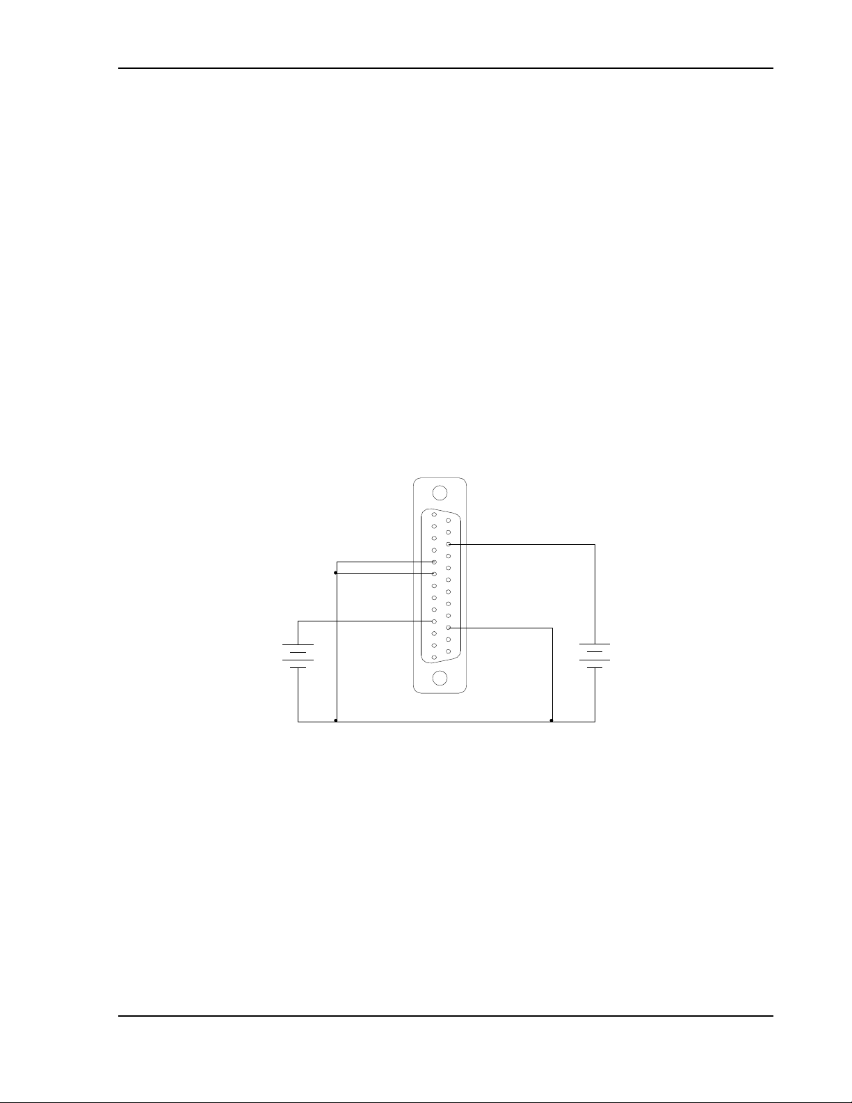
Calibration and Verification Sorensen SGI Series
+
-
1
13
23 IP RTN
COM 6
+
-
16 IP 10V
IP 5V 10
0-5 VDC
VOLTAGE
SOURCE
0-10 VDC
VOLTAGE
SOURCE
3.10.2 Remote Current Programming by Voltage Source
Two inputs are provided for remote voltage-programming of the output current:
5 VDC full-scale and 10 VDC full-scale. The DC voltage source is connected
between Pin J1-10 (IP 5 V) for 5 VDC source, or Pin J1-16 (IP 10 V) for
10 VDC source, and the return Pin J1-23 (IP RTN).
The corresponding voltage-programming coefficients for output current are
(100% rated output current) / 5 VDC, or (100% rated output current) /10 VDC,
from the respective inputs with return to Pin J1-23 (IP RTN). This produces
transfer functions for output current, as follows:
Iout = Vdc * (100% rated output current) / 5 VDC), with Vdc in volts, or
Iout = Vdc * (100% rated output current) / 10 VDC), with Vdc in volts.
Note:
The return Pin J1-23 (IP RTN) must be referenced directly to, or within
±3 V, of the circuit common, Pins J1-6 and J1-24. See Figure 3-15 for
connection requirements.
Figure 3-15. Remote Current Programming Using 0-5 VDC or 0-10 VDC Source
3-46 M550221-01 Rev AA
Page 99
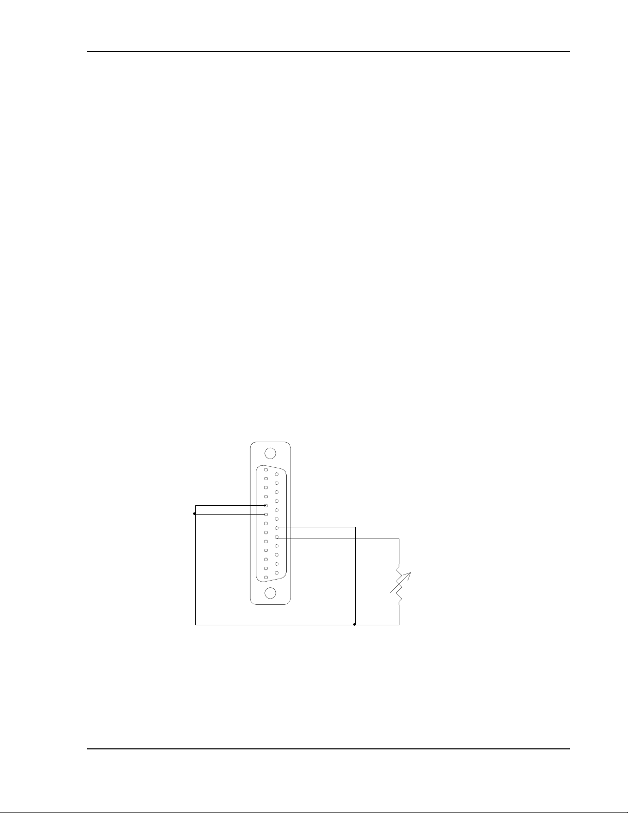
Sorensen SGI Series Calibration and Verification
1
13
14
20 VP RTN
21 VP RES
COM 6
0-5 Kohms
PROGRAM
3.11 Remote Voltage Programming
Remote voltage programming is summed with the front panel or digital setting;
see Section 3.9. Remote voltage programming configuration is used for
applications that require the output voltage be programmed (controlled) from a
remote instrument. An external resistance or external voltage source may be
used as a programming device. When using remote voltage programming, a
shielded, twisted-pair cable is recommended to prevent noise interference to
programming signals.
3.11.1 Remote Voltage Programming by Resistance
The resistance-programming coefficient for output voltage is
(100% rated output voltage) / 5 kΩ, with input at Pin J1-21 (VP RES) and
return to Pin J1-20 (VP RTN). An internal current source, factory-set at
1 mA, from Pin J1-21 (VP RES) is utilized to drive the resistance. This
produces a transfer function for output voltage, as follows:
Vout = R * (100% rated output voltage) / 5 kΩ), with R in ohms.
Note:
If an external resistance is used for remote programming, the voltage
programming return Pin J1-20 (VP RTN) must be connected directly to, or
within ±3 V, of the circuit common, Pins J1-6 and J1-24. See Figure 3-16 for
connection requirements.
Figure 3-16. Remote Voltage Programming Using Resistance
M550221-01 Rev AA 3-47
Page 100
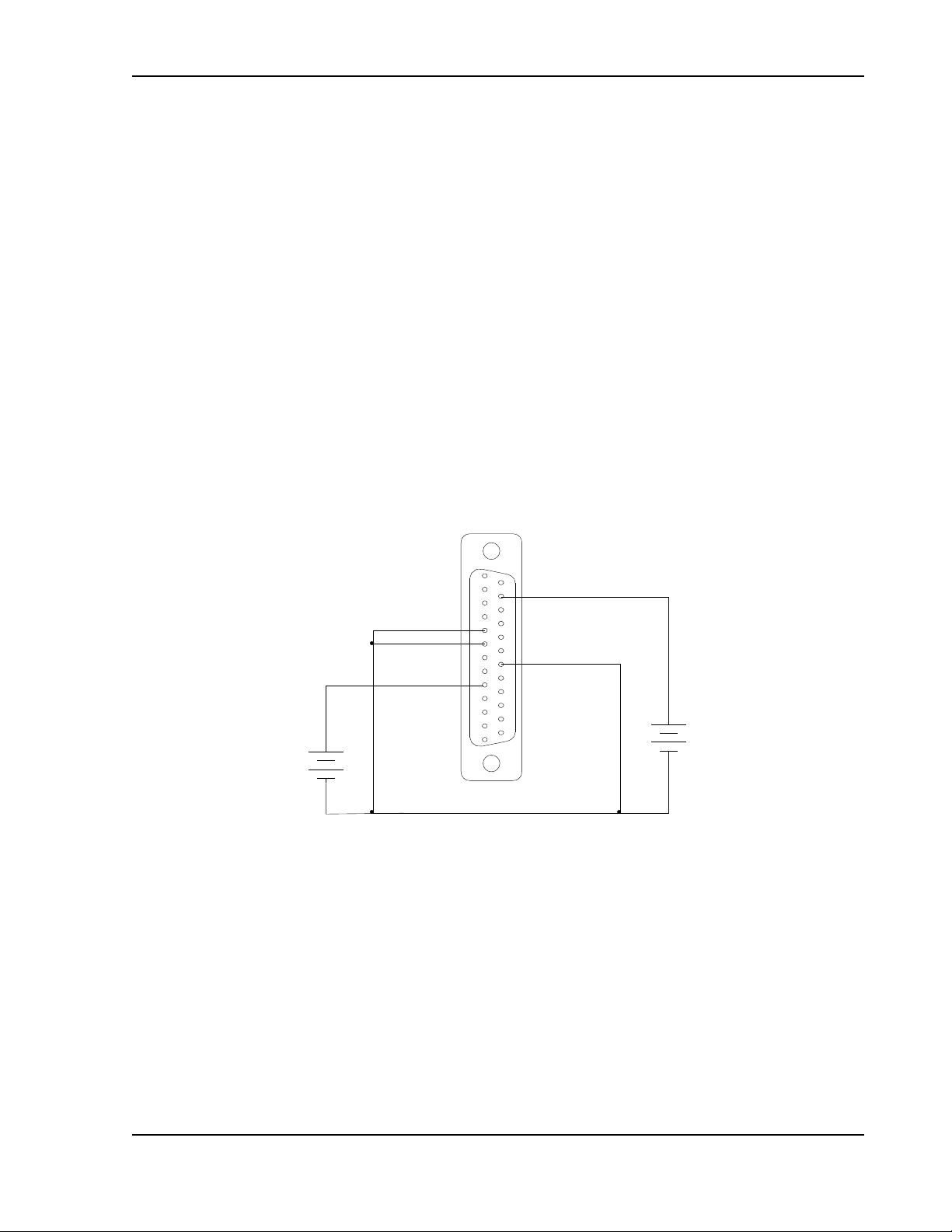
Calibration and Verification Sorensen SGI Series
+
-
1
13
20 VP RTN
COM 6
+
-
15 VP 10V
VP 5V 9
0-5 VDC
VOLTAGE
SOURCE
0-10 VDC
VOLTAGE
SOURCE
3.11.2 Remote Voltage Programming by Voltage Source
Two inputs are provided for remote voltage-programming of the output voltage:
5 VDC full-scale and 10 VDC full-scale. The DC voltage source is connected
between Pin J1-9 (VP 5 V) for 5 VDC source, or Pin J1-15 (VP 10 V) for 10
VDC source, and the return terminal J1-20 (VP RTN).
The corresponding voltage-programming coefficients for output voltage are
(100% rated output voltage) / 5 VDC, or (100% rated output voltage) /10 VDC,
from the respective inputs with return to Pin J1-20 (VP RTN). This produces
transfer functions for output voltage, as follows:
Vout = Vdc * (100% rated output voltage) / 5 VDC), with Vdc in volts, or
Vout = Vdc * (100% rated output voltage) / 10 VDC), with Vdc in volts.
Note:
The return terminal (VP RTN) must be referenced directly to, or within
±3 V, of the circuit common, Pins J1-6 and J1-24. See Figure 3-17 for
connection requirements.
Figure 3-17. Remote Voltage Programming Using 0-5 VDC or 0-10 VDC Source
3-48 M550221-01 Rev AA
 Loading...