

Page 1

SF Series
IEEE-488.2/RS-232 Option
Programming Manual
Power Supplies
Elgar Electronics Corporation
9250 Brown Deer Road
San Diego, CA 92121-2294
1-800-73ELGAR (1-800-733-5427)
Tel: (858) 450-0085
Fax: (858) 458-0267
Email: sales@elgar.com
www.elgar.com
©2004 by Sorensen, Division of Elgar Electronics Corporation
This document contains information proprietary to Sorensen, Elgar Electronics Corporation. The information
contained herein is not to be duplicated or transferred in any manner without prior written permission from Sorensen.
November 5, 2004 Document No. M550292-03 Rev 01
Page 2

.
Page 3
SAFETY NOTICE
Before applying power to the system, verify that the SF Series supply is configured properly for the user’s
particular application.
WARNING!
HAZARDOUS VOLTAGES IN EXCESS OF 280 VRMS, 600V PEAK MAY BE
PRESENT WHEN COVERS ARE REMOVED. QUALIFIED PERSONNEL MUST
USE EXTREME CAUTION WHEN SERVICING THIS EQUIPMENT. CIRCUIT
BOARDS, TEST POINTS, AND OUTPUT VOLTAGES MAY BE FLOATING
ABOVE (BELOW) CHASSIS GROUND.
Installation and service must be performed by qualified personnel who are aware of dealing with
attendant hazards. This includes such simple tasks as fuse verification.
Ensure that the AC power line ground is connected properly to the SFI Series unit input connector
or chassis. Similarly, other power ground lines including those to application and maintenance
equipment must
Always ensure that facility AC input power is de-energized prior to connecting or disconnecting the
input/output power cables.
inadvertent contact with hazardous voltages is eliminated. To guard against risk of electrical shock during
open cover checks, do not touch
capacitors can retain an electrical charge. Use safety glasses during open cover checks to avoid
personal injury by any sudden failure of a component.
be grounded properly for both personnel and equipment safety.
During normal operation, the operator does not have access to hazardous voltages within
the chassis. However, depending on the user’s application configuration, HIGH VOLTAGES
HAZARDOUS TO HUMAN SAFETY may be generated normally on the output terminals.
Ensure that the output power lines are labeled properly as to the safety hazards and that any
any portion of the electrical circuits. Even when the power is off,
Due to filtering, the unit has high leakage current to the chassis. Therefore, it is essential to operate this
unit with a safety ground.
Some circuits are live even with the front panel switch turned off. Service, fuse verification, and
connection of wiring to the chassis must be accomplished at least five minutes
been removed via external means; all circuits and/or terminals to be touched must be safety
grounded to the chassis.
After the unit has been operating for some time, the metal near the rear of the unit may be hot enough to
cause injury. Let the unit cool before handling.
Qualified service personnel need to be aware that some heat sinks are not at ground, but at high
potential.
These operating instructions form an integral part of the equipment and must be available to the
operating personnel at all times. All the safety instructions and advice notes are to be followed.
Neither Elgar Electronics Corporation, San Diego, California, USA, nor any of the subsidiary sales
organizations can accept any responsibility for personal, material or consequential injury, loss or damage
that results from improper use of the equipment and accessories.
after power has
Page 4
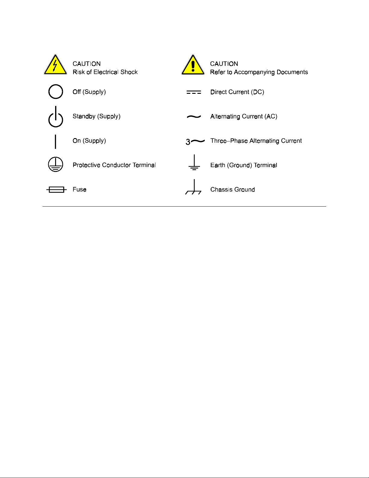
SAFETY SYMBOLS
Page 5

SECTION 1
1.1 Introduction......................................................................................................1-1
1.2 Features and Functions...................................................................................1-1
1.3 Specifications...................................................................................................1-2
SECTION 2
2.1 Setup Procedure..............................................................................................2-1
2.2 Rear Panel Configuration Switch.....................................................................2-2
2.2.1 Remote/Local Selection.......................................................................2-2
2.2.2 Power-On GPIB Service Request (PON SRQ) Selection....................2-3
2.2.3 Shield Ground......................................................................................2-3
2.2.4 Address Selection................................................................................2-3
2.3 Remote Programming Via RS-232..................................................................2-4
CONTENTS
FEATURES, FUNCTIONS, AND SPECIFICATIONS ....1-1
CONFIGURATION......................................................2-1
SECTION 3
3.1 Introduction......................................................................................................3-1
3.2 IEEE-488.2 Register Definitions......................................................................3-1
3.2.1 SCPI Status Byte.................................................................................3-1
3.2.2 Standard Event Status Register (ESR)................................................ 3-2
3.2.3 Protection Condition and Protection Event Status Register ................3-3
3.2.4 Operation Status and Questionable Status Registers.........................3-3
3.2.5 Error/Event Queue...............................................................................3-3
3.2.6 Serial Poll Operation............................................................................3-6
3.3 IEEE-488.2 and SCPI Conformance Information ............................................3-6
3.3.1 Parameter Definitions..........................................................................3-6
3.3.2 Units.....................................................................................................3-7
3.3.3 Conventions.........................................................................................3-7
3.3.4 Queries................................................................................................3-7
3.4 IEEE-488.2 Common Command Subsystem...................................................3-8
3.5 SOURCE SCPI Command Subsystem............................................................ 3-9
M550292-03 (Programming) i
IEEE 488.2 AND SCPI COMMAND OPERATION ........3-1
Page 6

Contents Sorensen SF Series
3.5.1
3.5.2 SOURCE SCPI Command Reference ...............................................3-10
3.6 MEASURE SCPI Command Subsystem........................................................3-12
3.6.1 MEASURE SCPI Command Summary..............................................3-12
3.6.2 MEASURE SCPI Command Reference.............................................3-13
3.7 OUTPUT SCPI Command Subsystem...........................................................3-14
3.7.1 OUTPUT SCPI Command Summary.................................................3-14
3.7.2 OUTPUT SCPI Command Reference................................................3-14
3.8 STATUS SCPI Command Subsystem ...........................................................3-15
3.8.1 STATUS SCPI Command Summary..................................................3-15
3.8.2 STATUS SCPI Command Reference.................................................3-15
3.9 SYSTEM SCPI Command Subsystem...........................................................3-17
3.9.1 SYSTEM SCPI Command Summary.................................................3-17
3.9.2 SYSTEM SCPI Command Reference................................................3-17
3.10 TRIGGER SCPI Command Subsystem.........................................................3-19
3.10.1 TRIGGER SCPI Command Summary..............................................3-19
3.10.2 TRIGGER SCPI Command Reference ............................................3-19
3.11 CALIBRATION SCPI Command Subsystem..................................................3-19
3.11.1 CALIBRATION SCPI Command Summary......................................3-20
3.11.2 CALIBRATION SCPI Command Reference.....................................3-21
3.12 Examples of Using the SCPI Commands ......................................................3-22
SOURCE SCPI Command Summary...................................................3-9
SECTION 4
4.1 Introduction ......................................................................................................4-1
4.2 Setup for Calibration ........................................................................................4-1
4.3 Voltage Measurement/Readback Calibration...................................................4-2
4.4 Current Programming Calibration ....................................................................4-3
4.5 Current Measurement/Readback Calibration...................................................4-4
4.6 Current Programming and Readback Calibration............................................4-5
SECTION 5
List of Figures
Figure 2–1. SFA Configuration Switch.......................................................................2-2
Figure 2–2. RS-232 Rear Panel RJ-11 Connector Pinout.......................................... 2-4
Figure 2–3. SF to PC RS-232 Connection (RJ-11 to DB-9)......................................... 2-4
CALIBRATION .......................................................... 4-1
SCPI STATUS IMPLEMENTATION............................ 5-1
ii M550292-03 (Programming)
Page 7

SECTION 1
FEATURES, FUNCTIONS,
AND SPECIFICATIONS
1.1 Introduction
This manual covers the Digital Interface Adapter (DIA) for SF Series supplies. The DIA interface
card enables the user to operate from a computer via the IEEE-488.2 GPIB or RS-232 interface,
allowing full remote programming control and monitoring of the SF Series supply.
1.2
Features
• 16-bit programming and 16-bit readback of voltage and current
• IEEE-488.2 and SCPI compliant command set
Features and Functions
• Current Ramp functions
• Field-upgradable firmware via RS-232
• Soft calibration
• Rear panel IEEE-488.2 and RS-232 control interface
• Rear panel configuration switch
Programmable Functions
• Output current
• Soft limits for current
• Output enable/disable
• Maskable fault interrupt
• Hold and trigger
• Full calibration
M550292-03 (Programming) 1-1
Page 8

Features, Functions, and Specifications Sorensen SF Series
Readback Functions
• Actual measured voltage and current
• Current settings
• Soft current limit
• Status and Accumulated Status registers
• Programming error codes
• Fault codes
• Manufacturer, power supply model, and firmware version identification
1.3 Specifications
Programming Resolution
Current: 0.002% of full scale
Programming Accuracy
Current: ± ( 0.4% of maximum output current)*
Readback Resolution
Voltage: ± 0.002% of full scale
Current: ± 0.002% of full scale
Readback Accuracy
Voltage: ± ( 0.15% of full scale output voltage)
Current: ± ( 0.4% of full scale output current)*
* After 30 minutes operation with fixed line, load, and temperature.
Note: Refer to the SFA or SFI power supply Operation manual for effects of line regulation,
load regulation, and temperature on accuracy specifications.
Specifications subject to change without notice.
1-2 M550292-03 (Programming)
Page 9

SECTION 2
CONFIGURATION
The DIA is installed into the supply at the factory. Use the Setup Procedure described below to
configure the DIA for your system and application.
2.1
This procedure is a quick reference for the configuration requirements. Refer to Section 2.2 for
detailed information on the rear panel switches.
1. Set the rear panel Remote/Local switch to Remote (On or 1).
2. Set the rear panel Power On Service Request switch to No Service Request (Off or 0).
3. SFA - Set the GPIB address switches to the desired address.
Setup Procedure
Note: Valid GPIB addresses are 1-30.
SFI – From the Home menu page 3, press (F1) to enter the Remote menu. Select the
IEEE488 address for GPIB programming or baud rate for RS232.
4. Connect the GPIB or RS232 Interface Cable to the supply.
5. Connect power to the unit and turn on the unit.
6. Configure the controller to match the supply identification and configuration. Use one of the
available programs such as IBCONF from National Instruments for GPIB, or set the RS232
baud rate to 19200 for SFA or selected rate for SFI, 8 data bits, no parity, and 1 stop bit.
7. Test the communication interface by issuing a *IDN? Command. This returns the supply’s
model and firmware versions and does not affect the output of the supply.
M550292-03 (Programming) 2-1
Page 10
Configuration Sorensen SF Series
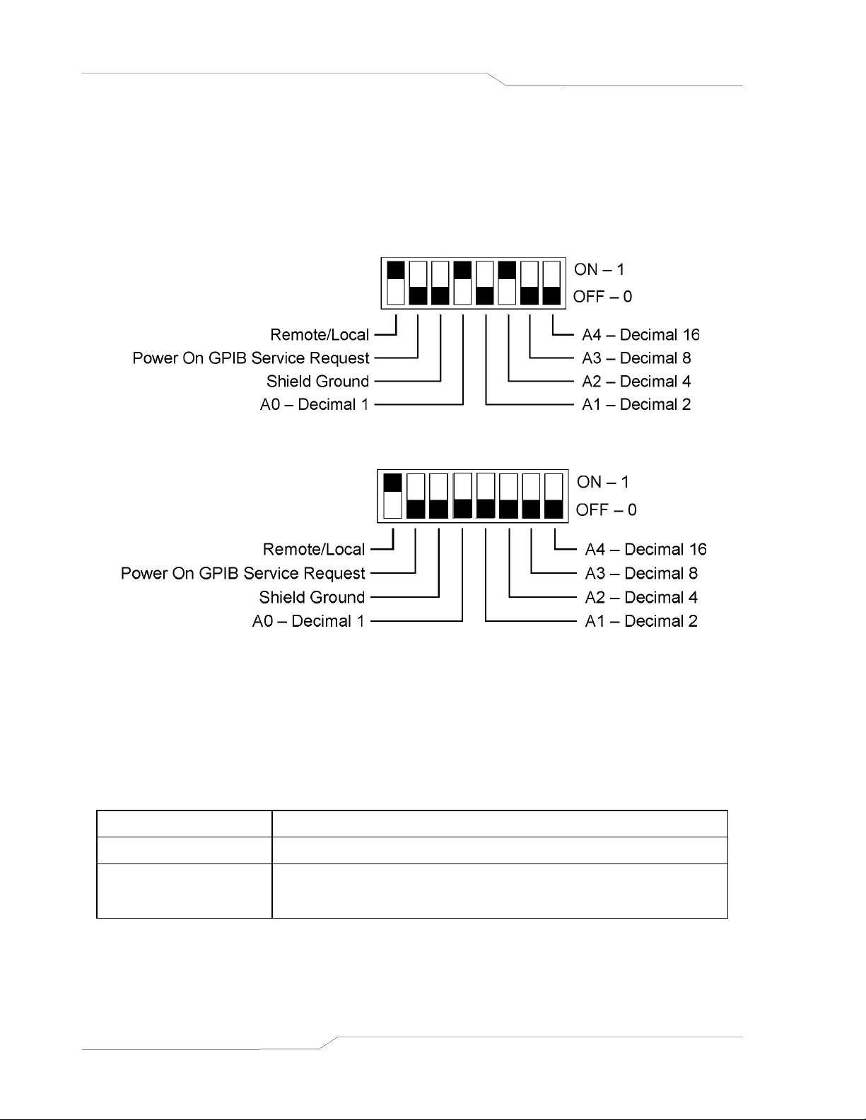
2.2 Rear Panel Configuration Switch
The DIP switch is accessible from the rear panel to allow configuration of the supply with the
installed DIA for the user’s particular system and application. The following figures show the
configuration, as set up in Section 2.1, and with GPIB address set to five (5) for the SFA.
Note: Two types of DIP switches are utilized; toggle and rocker. For toggle switches, the
shading indicates the position of the toggle switch. For rocker switches, the shading
indicates the depressed side.
Figure 2–1. SFA Configuration Switch
Figure 2–2. SFI Configuration Switch
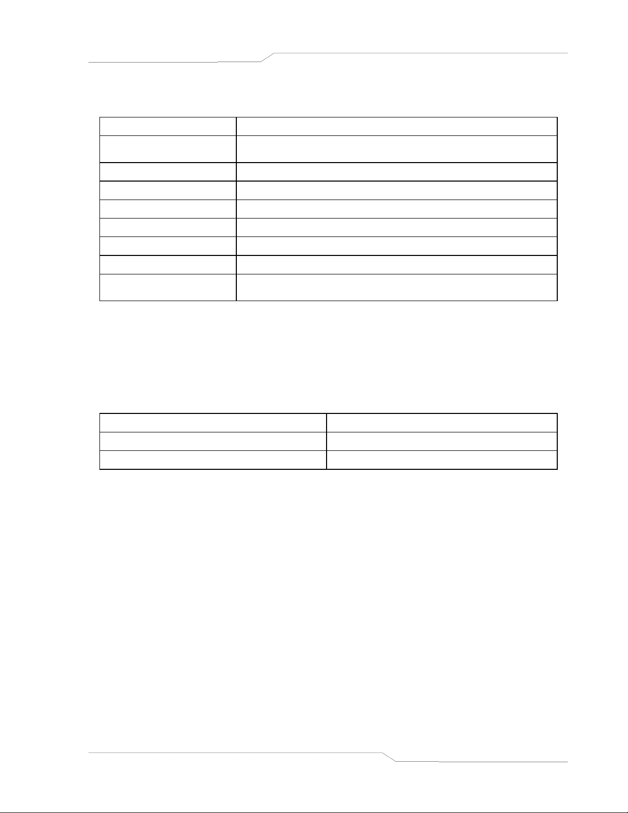
2.2.1 Remote/Local Selection
Set the rear panel Remote/Local switch to select remote or local operation.
REMOTE/LOCAL SWITCH
Switch Position Description
ON Remote operation selected. *
Local operation selected.
OFF
Front panel control is enabled. Unit will switch to remote
operation upon the first GPIB or RS-232 command.
* In the ON position, the power hardware and GPIB card initialize to the remote state on
power turn on. In addition, front panel control remains disabled regardless of the state of
the GPIB interface REN line or the GTL command. The special command SYST:LOCAL
<on/off> is permitted as a means to revert to front panel control if desired.
2-2 M550292-03 (Programming)
Page 11
Sorensen SF Series Configuration
Powering up in remote mode will result in the following operating conditions:
REMOTE MODE POWER-ON CONDITIONS
Condition Default
Current
Soft Current Limit Model maximum current
Delay 0.5 seconds
Foldback Protection OFF
Output ON
Hold OFF
Unmask NONE
Service Request
Capability
Initial power–on current. Default value = OA. See
CAL:INIT:CURR
OFF
2.2.2 Power-On GPIB Service Request (PON SRQ) Selection
Set the rear panel PON SRQ switch to ON to cause a GPIB service request to be sent to the
computer controller when the supply is turned on.
POWER-ON GPIB SERVICE REQUEST (PON SRQ) SWITCH
Switch Position Description
ON Power-On SRQ selected
OFF No Power-On SRQ selected
Refer to your specific GPIB controller card manual for further details on serial polling.
2.2.3
Connects GPIB cable shield to chassis ground.
2.2.4
The SFA address selection is binary with switch A0 as the LSB and A4 as the MSB. The rear
panel switch illustration in Section 2.2 shows the address selection 00101 in binary (5 decimal).
The SFI address is selected and enabled from a list in the Remote menu. See SFI Operation
manual for more details on Remote menu, Navigation and Editing.
Shield Ground
Address Selection
The address selection for a unit is the GPIB address of that device (1-30). SCPI reserves
channel 0 as the global channel to address all channels.
M550292-03 (Programming) 2-3
Page 12
Configuration Sorensen SF Series
ADDRESS SWITCHES
Switch Position Description
ON 1
OFF 0
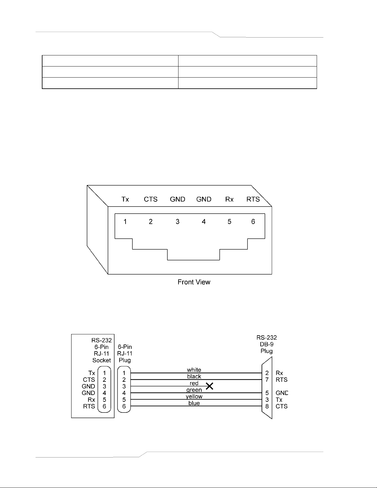
2.3 Remote Programming Via RS-232
The DIA’s RS-232 interface operates at fixed 19.2Kbaud for SFA and is selectable from 2400 to
19.2Kbaud for the SFI, with 8 data bits, no parity, and 1 stop bit. All DIA commands are
supported at the RS-232 interface with the exception of the Service Request (SRQ) function
which is a GPIB-specific function requiring the dedicated Service Request line of the IEEE-
488.2 interface. In this case, the SRQ function has no effect. The RS-232 interface is
accessible through the rear panel 6-pin RJ-11 connector. The connector is labeled RS232.
Figure 2–2. RS-232 Rear Panel RJ-11 Connector Pinout
Rear Panel To PC
Figure 2–3. SF to PC RS-232 Connection (RJ-11 to DB-9)
2-4 M550292-03 (Programming)
Page 13

SECTION 3
IEEE 488.2 AND SCPI
COMMAND OPERATION
3.1
The following sections describe the operation of the DIA by remote programming using the DIA
IEEE-488.2 and SCPI command sets. The DIA IEEE488.2 and SCPI command sets provide
programming, query, and status commands that facilitate remote control of the power supply.
3.2
The DIA supports the IEEE-488.2 and SCPI 1995.0 status reporting data structures. These
structures are comprised of status registers and status register enable mask pairs. The
following sections describe these pairs.
Introduction
IEEE-488.2 Register Definitions
3.2.1
The SCPI Status Byte status register can be read by the *STB? command or by issuing a GPIB
serial poll. The Status Byte status register can be cleared by the use of the *CLS command.
The DIA can be configured to request service from the GPIB controller by setting the
appropriate bits in the Service Request Enable Register (SRE). The SRE register has the same
bit pattern as the Status Byte. It is modified using the *SRE <mask> command and read with
the *SRE? command. For example, if the SRE register is set to 0x10 (MAV), when the DIA unit
has a message available, the Status Byte register will contain 0x50 (RQS and MAV) and the
SRQ line of the GPIB will be asserted to indicate a request for service. See table below, and
refer to Section 5 for further information.
SCPI Status Byte
M550292-03 (Programming) 3-1
Page 14

IEEE 488.2 and SCPI Command Operation Sorensen SF Series
SCPI STATUS BYTE
Bit Hex Value Description
0 0x01
1 0x02
2 0x04
3 0x08
4 0x10
5 0x20
6 0x40
7 0x80
Not used.
Protection Event Status flag. Indicates the selected protection
event occurred.
Error/event queue message available. Set when any error/event is
entered in the System Error Queue. It is read using the
SYSTem:ERRor? query.
Questionable Status flag. Indicates the quality of the current data
being acquired. This bit is not used.
Message available (MAV). Indicates a message is available in the
GPIB output queue. Cleared after the GPIB output buffer is read.
Standard Event Status Register (ESR). Summary bit for the ESR.
Set when any of the ESR bits are set and cleared when the ESR is
read.
Request Service flag (RQS) for serial polling or Master Summary
Status (MSS) in response to *STB? If service requests are enabled
(with the *SRE command), this bit represents the RQS and will be
sent in response to a serial poll, then cleared. If RQS is not
enabled, the bit represents the MSS bit and indicates the device
has at least one reason to request service. Even though the device
sends the MSS bit in response to a status query (*STB?), it is not
sent in response to a serial poll. It is not considered part of the
IEEE-488.1 Status Byte.
Operation Status flag. Indicates the current operational state of the
unit. This bit is not used.
3.2.2 Standard Event Status Register (ESR)
The Standard Event Status Register (ESR) can be read by the *ESR? command. Reading this
register or issuing a *CLS command will clear the ESR. Use the *ESE (Standard Event Status
Enable Register) to enable corresponding ESR bits to be summarized in the summary bit of the
SCPI Status byte. To configure the DIA to generate GPIB service requests based on the ESR,
both the Standard Event Status Enable Register and the Service Request Enable Register must
be programmed. See table below, and refer to Section 5 for further information.
STANDARD EVENT STATUS REGISTER
Bit Hex Value Description
0 0x01 Operation Complete
1 0x02 Request Control - not used
2 0x04 Query Error
3 0x08 Device Dependent Error
4 0x10 Execution Error (e.g., range error)
5 0x20 Command Error (e.g., syntax error)
6 0x40 User Request - not used
7 0x80 Power On
3-2 M550292-03 (Programming)
Page 15

Sorensen SF Series IEEE 488.2 and SCPI Command Operation
3.2.3 Protection Condition and Protection Event Status Register
These two registers have the same bit meanings, but they differ in regards to how they function.
The Protection Condition Register can be read using the STAT:PROT:COND? command. This
command gives the present status condition of the power hardware, so the data is not latched.
It is meant to be used as a polling register.
The Protection Event Status Register can be read by the STATus:PROTection:EVENt?
command. Reading this register, issuing a *CLS command, or issuing a *RST command will
clear the Protection Event Status Register. Bits in the Protection Event Status Register will be
set only when the corresponding bit in the Protection Event Status Enable Register is set and
the corresponding event occurs. The status is then latched and will remain in that state until it is
read or cleared due to some command action. (Use the STATus:PROTection:ENABle <mask>
command to set the Enable Register and the STATus:PROTection:ENABle? query to read the
Enable Register.) To configure the DIA to generate GPIB service requests based on the
Protection Event Status Register, both the Protection Event Status Enable Register and the
Service Request Enable Register (*SRE) must be programmed. For further information, refer to
the table below, and to Section 5.
PROTECTION CONDITION AND EVENT STATUS REGISTERS
Bit Hex Value Description
0 0x01 Not used
1 0x02 Constant current operation
2 0x04 Not used
3 0x08 Overvoltage protection tripped (not applicable for SFA)
4 0x10 Overtemperature protection tripped
5 0x20 Supply external shutdown active
6 0x40 Foldback mode operation
7 0x80 Remote programming error
3.2.4
The Operation Status and Questionable Status Registers will always return 0 when queried.
The Operation Status Enable and Questionable Status Enable Registers can be programmed
and queried to allow SCPI compatibility but have no effect on the Operation Status and
Questionable Status Registers.
3.2.5
Operation Status and Questionable Status Registers
Error/Event Queue
The DIA maintains an Error/Event Queue as defined by SCPI. The queue holds up to 10 error
events. It is queried using the SYSTem:ERRor? command which reads in a First In/First Out
(FIFO) manner. The read operation removes the entry from the queue. The *CLS command
will clear all entries from the queue.
The following error codes are defined in the SCPI 1995.0 specification and are supported by the
DIA. Error codes are in the range of [-32768, 32767]. SCPI reserves the negative error codes
and 0, while error codes greater than 0 are device specific errors.
M550292-03 (Programming) 3-3
Page 16

IEEE 488.2 and SCPI Command Operation Sorensen SF Series
SCPI ERROR CODES
Error Code Description
206
205
204
203
202
201
102
100
0
-102
-108
-151
-161
No channels setup to trigger
This means that an attempt was made to trigger the DIA using the
TRIG:TYPE <1|2|3> command when there are no armed trigger settings.
This error is not generated when the GET is received, even when there are
no armed trigger settings.
GPIB GET not allowed during message
This error means that the GPIB G(roup) E(xecute) T(rigger) multiline
command was errantly generated by the system computer while or very
shortly after a message is or was sent. Give a few milliseconds after a
message was sent before attempting a GET; and never send a GET during
the midst of a message transfer over the GPIB.
GPIB IFC caused warm boot
This error relates to the GPIB IFC signal, and is available only in
association with a proprietary command.
Hardware watchdog warm boot
This error is caused by a hardware fault either in the power supply proper,
or on the DIA. One possible explanation might be that the mains power to
the supply was interrupted for a short but sufficient time to cause the DIA
processor to reset and re-boot. Also, it might be possible to generate this
error by a very momentary off action of the front panel power switch.
Foreground watchdog warm boot
This error means that the internal firmware on the DIA found an internal
error condition that halted processing; to force resumption of processing, a
warm boot was required.
Unexpected warm boot
This error means that the DIA GPIB-side processor experienced a warm
boot that was unexpected, and it may indicate an internal crash of the DIA
processor.
Incompatible unit type
This error is not used. It cannot occur.
Incompatibility error
This error is not used. It cannot occur.
No error
The error queue is empty.
Syntax error
An unrecognized command or data type was encountered.
Parameter not allowed
More arguments than expected were received.
Invalid string data
Incorrect password. Manufacturer, model, or serial number string was
more than 16 characters. Invalid mnemonic.
Invalid block data
The expected number of data values was not received.
3-4 M550292-03 (Programming)
Page 17

Sorensen SF Series IEEE 488.2 and SCPI Command Operation
Error Code Description
-200
-203
-221
-222
-225
-241
-284
-292
-293
-316
-330
-340
-350
-360
Execution error
An error/event number in the range [-299,-200] indicates that an error has
been detected by the instruments execution control block. The occurrence
of any error in this class shall cause the execution error bit (bit 4) in the
Event Status Register to be set. An execution error can be the result of:
• A <program data> element out of range, such as programming 35 volts
in a 33 volt device.
• A command could not be executed due to the current condition of the
device.
Command protected
Attempted to store calibration values to EEPROM without unlocking.
Settings conflict
Attempted to set output greater than soft limits or to set soft limits less than
output.
Data out of range
Parameter exceeded range of valid values.
Out of memory
There is not enough memory to perform the requested operation.
Hardware missing
A legal command or query could not be executed because of a hardware
fault.
Program currently running
A legal command or query could not be executed because a function is
currently running.
Referenced name does not exist
Referenced name already exists
Checksum error
Self-test failed
A self-test failure has occurred.
Calibration failed
Error during calculation of calibration values occurred.
Queue overflow
The error queue can contain up to 10 entries. If more than 10 error/event
conditions are logged before the SYSTem:ERRor? query, an overflow will
occur; the last queue entry will be overwritten with error -350. When the
queue overflows, the least recent error/events remain in the queue and the
most recent error/events are discarded.
Communication error
Communications to a channel was disrupted.
M550292-03 (Programming) 3-5
Page 18

IEEE 488.2 and SCPI Command Operation Sorensen SF Series
3.2.6
Performing a serial poll will not modify the Status Byte other than to clear the RQS (bit 6) for an
DIA requesting service. Queries affecting the Status Registers and subsequent serial poll are
described below:
• *STB? clears the Status Byte
• *ESR? clears the ESR and bit 5 of the Status Register
• SYSTem:ERRor? clears bit 2 of the Status Register if the queue is empty
Serial Poll Operation
3.3
The DIA conforms to most of the specifications for devices as defined in IEEE-488.2 and SCPI
Version 1995.0. Confirmed Commands are those that are approved in the SCPI 1995
Specification, Volume 2: Command Reference. They are denoted by a “C” in the “SCPI”
column. Any commands that are not Confirmed Commands are labeled as Not Approved
denoted by an “N.”
3.3.1
IEEE-488.2 and SCPI Conformance Information
Parameter Definitions
PARAMETER DEFINITIONS
Type Valid Arguments
<boolean> “ON” or 1. “OFF” or 0.
<NR1>
<0+NR1> Zero and positive integer numeric values.
<-NR1> Negative integer numeric values.
<NRf>
<0+NRf> Zero and positive floating point numeric values.
The data format <NR1> is defined in IEEE-488.2 for integers.
Zero, positive and negative integer numeric values are valid data.
The data format <NRf> is defined in IEEE-488.2 for flexible Numeric
Representation. Zero, positive and negative floating point numeric
values are some examples of valid data.
<-NRf> Negative floating point numeric values.
<string> Characters enclosed by single or double quotes.
3-6 M550292-03 (Programming)
Page 19

Sorensen SF Series IEEE 488.2 and SCPI Command Operation
3.3.2 Units
The Series DIA will accept the following units as suffixes to numeric values:
UNITS
Type of Unit Valid Suffix
Voltage “VOLTS” or “volts”, “V” or “v”, “MV” or “mv” or “mV”
Current “AMPS” or “amps”, “A” or “a”, “MA” or “ma” or “mA”
Time “SEC” or “sec”, “S” or “s”, “MS” or “ms”, “MIN” or “min”
Frequency “HZ” or “hz”
The default units are VOLTS, AMPS, SEC, and HZ. For example, “SOUR:VOLT 1” programs 1
volt. To program in units of millivolts, type “SOUR:VOLT 1mV”.
3.3.3 Conventions
SCPI uses the conventions where optional commands and parameters are enclosed by “[ ]”.
Additionally the shorthand version of a command is indicated by capital letters. The DIA
supports Channel 1 only.
For example,
Source: CURRent[:LEVel][:IMMediate][:AMPLitude] 120.0
can be written as
SOURce:CURRent 120.0
or
SOUR:CURR 120.0
3.3.4 Queries
The query syntax is identical to the command syntax with a “?” appended. For example, to
query the programmed voltage, send the string: SOURce:CURRent?. A subsequent device
read will return a value such as “33.000”. All queries are terminated with a carriage return and
line feed (0x0D 0x0A) for those GPIB controllers that require termination characters. When the
DIA has nothing to report, its output buffer will contain two ASCII characters: a carriage return
and linefeed (in decimal the values are: <13><10>).
Note: Commands with associated queries are noted with a "Q" in the Q? column of the SCPI
documentation tables.
M550292-03 (Programming) 3-7
Page 20

IEEE 488.2 and SCPI Command Operation Sorensen SF Series
3.4 IEEE-488.2 Common Command Subsystem
The following commands are common to all SCPI instruments and declared mandatory by
IEEE-488.2. In the following table, the DIA is defined as the “device” on the GPIB bus. A "C" in
the SCPI column indicates that a command is SCPI-compliant.
Command Description SCPI
*CLS
*ESE
<0+NR1>
*ESE?
*ESR?
Clears all status reporting data structures including the Status
Byte, Standard Event Status Register, and Error Queue. The
STAT:PROT:ENAB (protection event enable register) is cleared
by this command; other enable registers are not cleared by this
command.
Sets the value of the Standard Event Status Enable Register that
determines which bits can be set in the Standard Event Status
Register. See section 3.2.2 for valid values.
Returns the integer value of the Standard Event Status Enable
Register. See section 3.2.2 for valid values.
Response: <0+NR1>
Returns the integer value of the Standard Event Status Register.
The ESR and the Status Byte ESR bit are cleared. See section
3.2.2 for valid values.
C
C
C
C
*IDN?
*OPC
*OPC?
*RST
*SRE
<0+NR1>
*SRE?
Response: <0+NR1>
Returns the device identification as an ASCII string.
Response: <Manufacturer>, <model>, <serial number>,
<DCI firmware version> <AI firmware version>
Example: Sorensen, SFA 100/150C-1AAA, YYWWC#####,
1.00,1.00
Enables the Operation Complete bit of the Standard Event Status
Register to be set when all pending operations are complete.
See section 3.2.2.
Returns the integer value “1” when all pending operations are
complete. See section 3.2.2.
Response: <0+NR1>
Resets the supply to its Power ON (PON) state.
Clears all status reporting data structures including the Status
Byte, Standard Event Status Register, and Error Queue. The
STAT:PROT:ENAB (protection event enable register) is cleared
by this command; other enable registers are not cleared by this
command.
Sets the value of the Service Request Enable Register, which
determines which bits in the Status Byte will cause a service
request from the device. See section on Status Byte for valid
values.
Returns the integer value of the Service Request Enable
Register. See section on Status Byte for valid values. Values
range from 0-63 or 128-191.
C
C
C
C
C
C
Response: <0+NR1>
3-8 M550292-03 (Programming)
Page 21

Sorensen SF Series IEEE 488.2 and SCPI Command Operation
Command Description SCPI
*STB?
*TST?
*WAI
Returns the integer value of the Status Byte with bit 6
representing the Master Summary Status (MSS) instead of RQS.
The MSS bit acts as a summary bit for the Status Byte and
indicates whether the device has at least one reason to request
service based on the MAV and the ESR bits. The Status Byte is
cleared. See section on Status Byte for valid values. Values
range from 0-255.
Response: <0+NR1>
Sets the device to execute an internal self-test and return the
integer value of the results. Value of “0” indicates no errors.
Response: <0+NR1>
Sets the device to wait until all previous commands and queries
are complete before executing commands following the *WAI
command.
C
C
C
3.5
3.5.1
SOURce
:CURRent
:CURRent?
[:LEVel]
[:LEVel?]
[:IMMediate]
[:IMMediate?]
[:AMPLitude] <0+NRf>
[:AMPLitude?]
:TRIGgered
:TRIGgered?
:CLEar
[:AMPLitude] <0+NRf>
[:AMPLitude?]
:LIMit
:LIMit?
[:AMPLitude] <0+NRf>
[:AMPLitude?]
:RAMP <0+NRf> <0+NRf>
:RAMP?
:ABORt
:ALL?
:TRIGgered <0+NRf> <0+NRf>
:TRIGgered?
:ONLine?
:STATus
:BLOCk?
:REGister?
:TIMeout?
SOURCE SCPI Command Subsystem
SOURCE SCPI Command Summary
M550292-03 (Programming) 3-9
Page 22

IEEE 488.2 and SCPI Command Operation Sorensen SF Series
3.5.2 SOURCE SCPI Command Reference
In the following table a "C" in the SCPI column indicates that the command is SCPI-compliant.
The Q? column indicates whether the command can also be used for querying.
Command Description SCPI Q?
SOURce
:CURRent
[:LEVel]
[:IMMediate]
[:AMPLitude]
<0+NRf>
:TRIGgered
:CLEar
[:AMPLitude]
<0+NRf>
:LIMit
[:AMPLitude]
<0+NRf>
:RAMP <0+NRf>
<0+NRf>
:ABORt
:ALL?
:TRIGgered
<0+NRf>
<0+NRf>
:ONLine?
Source subsystem. C
Sets the output current in amps (default) or in
milliamps.
Sets the output current in amps (default) or in
milliamps.
Sets the output current in amps (default) or in
milliamps.
Sets the output current in amps (default) or in
milliamps.
Sets the value of the output current to be
implemented by the trigger.
Clears the trigger mode.
Sets the value of the output current to be
implemented by the trigger.
Sets an upper soft limit on the programmed
output current for the supply. The soft limit
prevents the supply from being inadvertently
programmed above the soft limit, thus
providing a method for protecting the load
against damaging currents.
Sets an upper soft limit on the programmed
output current for the supply.
Sets the output current to ramp from the
present value to the specified value (first
argument) in the specified time (second
argument). See Ramp Function description
below.
Aborts ramping and clears trigger mode.
Returns the ramping status of all channels.
Sets the output current to ramp from the
present value to the specified value (first
argument) in the specified time (second
argument) upon the trigger command. See
Ramp description below.
Returns the integer value 1(ONLINE) or 0
(OFFLINE) of the channel online status.
C Q
C Q
C Q
C Q
C Q
C Q
C Q
C Q
N Q
N Q
N
3-10 M550292-03 (Programming)
Page 23

Sorensen SF Series IEEE 488.2 and SCPI Command Operation
Command Description SCPI Q?
:STATus
:BLOCk?
Returns the block of data critical to the status
of the channel:
1) channel number
2) online status
3) status flags register (see table below)
4) status register
5) accumulated status
6) fault mask register
7) fault register
8) error register
9) model serial number
10) model voltage
11) model current
12) model over-voltage
13) output voltage DAC gain
14) output voltage DAC offset
15) output current DAC gain
16) output current DAC offset
17) output voltage protection DAC gain
18) output voltage protection DAC offset
19) voltage measurement ADC gain
20) voltage measurement ADC offset
21) current measurement ADC gain
22) current measurement ADC offset
23) model string
24) OVP calibrated
N
:REGister?
:TIMeout?
Each value is separated by commas.
Returns the integer value of the status register.
See Section_5.
Returns the integer value 1 (timeout since last
query) or 0 (no timeout) of the timeout status of
the channel.
N
N
M550292-03 (Programming) 3-11
Page 24

IEEE 488.2 and SCPI Command Operation Sorensen SF Series
THE RAMP FUNCTION
The ramp function allows the user to transition from one current to another linearly in a specified
time period (100 ms - 99 sec with 100 ms programming resolution). A unit may ramp only
current.
Current ramping requires an appropriate resistive load.
SOURce[n]:STATus:BLOCK? "Status Flags" REGISTER
Bit Hex Value Name Description
0 0x001 remote mode Remote mode was selected.
1 0x002 Not used.
2 0x004 PON SRQ PON Service Request selected by rear panel switch.
3 0x008 SRQ sent
4 0x010 EEPROM The EEPROM is locked.
5 0x020 trip occurred Either an OV or OT trip occurred.
GPIB Service Request issued and the serial poll has
not been received.
6 0x040 sense signal Not used.
7 0x080 isolation signal Not used.
8 0x100 hold Current output waiting for trigger.
9 0x200 fold Foldback protection is enabled.
10 0x400 SRQ enabled Service Request generation is enabled.
11 0x800 output Output is on.
3.6
3.6.1
MEASure
:CURRent?
:CURRent
:AVErage <value>
:AVErage?
:VOLTage?
:VOLTage
:AVErage <value>
:AVErage?
MEASURE SCPI Command Subsystem
MEASURE SCPI Command Summary
3-12 M550292-03 (Programming)
Page 25

Sorensen SF Series IEEE 488.2 and SCPI Command Operation
3.6.2 MEASURE SCPI Command Reference
In the following table a "C" in the SCPI column indicates that the command is SCPI-compliant.
Command Description SCPI
MEASure
:CURRent?
:CURRent
:AVErage
<value>
:AVErage?
:VOLTage?
:VOLTage
:AVErage
<value>
:AVErage?
Measure subsystem. C
Returns the floating point value of the DC output
current in amps.
Enter a value of 1 to 5 to set the number of readings
to average together when returning the current value
from the MEAS:CURR? command. This function
reduces noise in the readback readings. The
(default) value of 1 provides the fastest response
time, but the noisiest readings.
Returns the number 1 to 5 to indicate the last set
number of readings to average together when taking
a current reading.
Returns the floating point value of the DC output
voltage in volts.
Enter a value of 1 to 5 to set the number of readings
to average together when returning the voltage value
from the MEAS:VOLT? command. This function
reduces noise in the readback readings. The
(default) value of 1 provides the fastest response
time, but the noisiest readings.
Returns the number 1 to 5 to indicate the last set
number of readings to average together when taking
a voltage reading.
C
N
N
C
N
N
M550292-03 (Programming) 3-13
Page 26

IEEE 488.2 and SCPI Command Operation Sorensen SF Series
3.7
3.7.1
OUTPut
:PROTection
:DELay <0+NRf>
:DELay?
:FOLD <0|1|2>
:FOLD?
:STATe <boolean>
:STATe?
:TRIPped?
3.7.2
In the following table a "C" in the SCPI column indicates that the command is SCPI-compliant.
The Q? column indicates whether the command can also be used for querying.
Command Description SCPI Q?
OUTPut
:PROTection
:DELay <0+NRf>
:FOLD <0|1|2>
:STATe <boolean>
:TRIPped?
OUTPUT SCPI Command Subsystem
OUTPUT SCPI Command Summary
OUTPUT SCPI Command Reference
Output subsystem. C
N
Sets the programmable time delay executed
by the supply before reporting output
protection conditions after a new output
current is specified.
Sets the foldback (program down) mode of
the supply. Valid arguments are 0 (OFF or do
nothing, do not program down to zero), 1(Not
used), or 2 (program down to zero upon
entering constant-current mode).
Sets the output to zero or the programmed
value. Valid arguments are 1/ON or 0/OFF.
*RST state value is ON.
Returns the integer value 1 (TRIPPED) or 0
(UNTRIPPED) state of the output.
N Q
N Q
C Q
N
3-14 M550292-03 (Programming)
Page 27

Sorensen SF Series IEEE 488.2 and SCPI Command Operation
3.8
Note: See Section 5 for further information.
3.8.1
STATus
:OPERation
:CONDition?
:ENABle <0+NR1>
:ENABle?
:EVENt?
:PRESet
:PROTection
:CONDition?
:ENABle <0+NR1>
:ENABle?
:EVENt?
:SELEct <0+NR1>
:QUEStionable
:CONDition?
:ENABle <0+NR1>
:ENABle?
:EVENt?
STATUS SCPI Command Subsystem
STATUS SCPI Command Summary
3.8.2
In the following table a "C" in the SCPI column indicates that the command is SCPI-compliant.
The Q? column indicates whether the command can also be used for querying.
STATus
:OPERation
:CONDition?
:ENABle <0+NR1>
:EVENt?
:PRESet
STATUS SCPI Command Reference
Command Description SCPI Q?
Status subsystem. C
C
Returns the integer value of the Operation
Condition Register. The query is supported
but will always return “0” indicating
operational condition.
Sets the enable mask of the Operation
Event Register allowing true conditions to
be reported in the summary bit of the
Operation Condition Register. Values are
written and queried but have no effect on
the Operation Condition Register.
Returns the integer value of the Operation
Event Register. This query is supported but
always returns a value of “0” indicating
operational condition.
Sets the enable mask of the Operation
Event Register and the Questionable Event
Register to all 1’s.
C
C Q
C
C
M550292-03 (Programming) 3-15
Page 28

IEEE 488.2 and SCPI Command Operation Sorensen SF Series
Command Description SCPI Q?
:PROTection
:CONDition?
:ENABle <0+NR1>
:EVENt?
:SELEct <0+NR1>
:SELEct?
:QUEStionable
:CONDition?
:ENABle <0+NR1>
:EVENt?
C
Returns the integer value of the Protection
Condition Register. Used to read the status
of the power hardware. See section 3.2.3
for a detailed table of the various bits that
make up this register.
Sets the enable mask of the Protection
Event Register which allows true conditions
to be reported in the summary bit of the
Protection Condition Register.
Returns the integer value of the Protection
Event Register.
This command provides a means for
selecting which fault bits from the protection
event register (also called the fault register
and readable using the STAT:PROT:EVEN?
command) are able to set the protection
event flag bit in the SCPI status byte
(readable using the *STB? command). It
defaults to value 255 at power-on time, and
never changes unless intentionally
programmed to a new value.
Queries the last selection value
programmed.
C
Returns the integer value of the
Questionable Condition Register. The
query is supported but will always return “0”
indicating operational condition.
Sets the enable mask of the Questionable
Event Register allowing true conditions to
be reported in the summary bit of the
Questionable Condition Register. Values
are written and queried but have no effect
on the Questionable Condition Register.
Returns the integer value of the
Questionable Event Register. This query is
supported but always returns a value of “0”,
indicating operational condition.
C
C Q
C
N
N
C
C Q
C
3-16 M550292-03 (Programming)
Page 29

Sorensen SF Series IEEE 488.2 and SCPI Command Operation
3.9
3.9.1
SYSTem
:ERRor?
:FAULt?
:VERsion?
:LOCAL <boolean>
:LOCAL?
:LOCLOUT <boolean>
3.9.2
In the following table a "C" in the SCPI column indicates that the command is SCPI-compliant.
The Q? column indicates whether the command can also be used for querying.
SYSTem
:ERRor?
:FAULt?
SYSTEM SCPI Command Subsystem
SYSTEM SCPI Command Summary
SYSTEM SCPI Command Reference
Command Description SCPI Q?
System subsystem. C
Queries Error Queue for next error/event entry
(first in, first out). Entries contain an error
number and descriptive text. A 0 return value
indicates no error occurred; negative numbers
are reserved by SCPI. The maximum return
string length is 255 characters. The queue
holds up to 10 error/entries. All entries are
cleared by the *CLS command.
Returns four numeric values separated by
commas for the four system fault registers. See
System Fault Registers below. Valid response
is 128, 0, 0, 0 or 0, 0, 0, 0.
C
N
Response: <Fault1–8>, <Fault9–16>,
<Fault17–24>, <Fault25–31>
:VERsion?
M550292-03 (Programming) 3-17
Returns a numeric value corresponding to the
SCPI version number for which the instrument
complies. The response is in the format
YYYY.V where the Y’s represent the year and
V represents the approved version number for
that year (e.g., 1995.0)
C
Page 30

IEEE 488.2 and SCPI Command Operation Sorensen SF Series
Command Description SCPI Q?
SYST:LOCAL
SYST:LOCAL:LOCKOUT
SYST:LOCAL <ON|OFF> is a special purpose
programming command that may be used to
cause source to be set to the local state or to
the remote state. This command has two
noteworthy circumstances under which it may
prove necessary. The first case involves using
RS232 to communicate with the supply, since
the normal GPIB mechanisms for transition
between local and remote and back again do
not exist when using RS232. The other case is
when the REMOTE/LOCAL switch S1-1 is
placed in the ON position—thereby disabling
the GPIB mechanism for transition from remote
to local. The SYST:LOCAL ON command
provides a means for the system computer to
force the source to the local state. Also, the
SYST:LOCAL? query command is available to
examine the local-remote state of the supply.
And the command SYST:LOCAL OFF may be
used to force supply to the remote state.
The SYST:LOCAL:LOCKOUT <0|1|OFF|ON>
command provides a means of controlling the
local lockout functionality that is an alternative
to the low level GPIB LLO command.
N Q
N
In contrast, using the GPIB LLO low level
command causes the supply to be placed into
the local lockout state. To place the supply into
the local lockout state, use the
SYST:LOCAL:LOCKOUT command.
SYSTEM FAULT REGISTERS
Bit Position Bit Weight Fault1–8 Fault9–16 Fault17–24 Fault25–31
7 128 Channel 1 not used not used not used
6 64 not used not used not used not used
5 32 not used not used not used not used
4 16 not used not used not used not used
3 8 not used not used not used not used
2 4 not used not used not used not used
1 2 not used not used not used not used
0 1 not used not used not used not used
The SYStem:FAULt? query returns 4 numeric values separated by commas. Each value is the
decimal equivalent of the total bit weights for that System Fault Register as described in the
table above.
3-18 M550292-03 (Programming)
Page 31

Sorensen SF Series IEEE 488.2 and SCPI Command Operation
3.10
3.10.1
TRIGger
:ABORt
:RAMP
:TYPE <1|2|3>
3.10.2
TRIGGER SCPI Command Subsystem
TRIGGER SCPI Command Summary
TRIGGER SCPI Command Reference
Command Description SCPI
TRIGger
:ABORt
:RAMP
:TYPe<1|2|3>
Trigger subsystem. C
Clears all settings of voltage and current
upon trigger.
Implements current ramping function
previously programmed by the
SOURce:CURRent:RAMP commands.
Implements current values previously
programmed by the
SOURce:CURRent:LEVel:TRIGger
commands.
Valid arguments are 1 (Not Used),
2 (Current), or 3 (Both).
N
N
N
3.11 CALIBRATION SCPI Command Subsystem
See Section 4 for calibration procedures.
WARNING
Please refer to the power supply manual for further information before performing
calibration procedures. Calibration must be performed by qualified personnel who
appropriately deal with attendant hazards. If calibration is not performed properly,
functional problems could arise, requiring that the supply be returned to the factory.
M550292-03 (Programming) 3-19
Page 32

IEEE 488.2 and SCPI Command Operation Sorensen SF Series
3.11.1 CALIBRATION SCPI Command Summary
CALibrate
:DATA <NRf><NRf><NRf><NRf><NRf><NRf><NRf><NRf><NRf><NRf>
:INITial
:CURRent <0+NRf>
:CURRent?
:PROTection <NRf>
:PROTection?
:LOCK
:MEASure
:CURRent
:ADC?
:CALCulate
:GAIN <NRf>
:GAIN?
:OFFSet <NRf>
:OFFSet?
:POINt <1|2> <0+NRf>
:VOLTage
:ADC?
:CALCulate
:GAIN <NRf>
:GAIN?
:OFFSet <NRf>
:OFFSet?
:POINt <1|2> <NRf>
:OUTPut
:CURRent
:CALCulate
:DAC <0+NR1>
:GAIN <NRf>
:GAIN?
:OFFSet <NRf>
:OFFSet?
:POINt <1|2> <NRf>
:STORe
:UNLock <string>
3-20 M550292-03 (Programming)
Page 33

Sorensen SF Series IEEE 488.2 and SCPI Command Operation
3.11.2 CALIBRATION SCPI Command Reference
In the following table a "C" in the SCPI column indicates that the command is SCPI-compliant.
The Q? column indicates whether the command can also be used for querying.
Command Description SCPI Q?
CALibrate
:DATA <NRf><NRf><NRf>
<NRf><NRf><NRf>
<NRf><NRf><NRf>
<NRf>
:INITial
:CURRent
:PROTection <NRf>
:LOCK
:MEASure
:CURRent
:ADC?
:CALCulate
:GAIN <NRf>
:OFFSet <NRf>
:POINt <1|2>
<0+NRf>
:VOLTage
:ADC?
:CALCulate
:GAIN <NRf>
:OFFSet <NRf>
Calibration subsystem. C
Sets the values of the ten floating point
calibration constants:
1) not used
2) not used
3) output current DAC gain
4) output current DAC offset
5) output current protection DAC gain
6) output current protection DAC offset
7) voltage measurement ADC gain
8) voltage measurement ADC offset
9) current measurement ADC gain
10) current measurement ADC offset
Values are separated by space or comma.
N
Sets the power-on default value of current. N Q
Sets the power-on default value of the
overcurrent protection.
Disables access to the non-volatile memory.
Prevents attempts to store calibration
values.
N
Returns the integer value of the A/D for the
current measurement.
Calculates the value of the gain and offset
for current measurements.
Sets the value of the gain for current
measurements.
Sets the value of the offset for current
measurements.
Sets the current measurement calibration
point (1 or 2). The actual output current is
measured with an external meter.
N
Returns the integer value of the A/D for the
voltage measurement.
Calculates the value of the gain and offset
for voltage measurements.
Sets the value of the gain for voltage
measurements.
Sets the value of the offset for voltage
measurements.
N
N Q
N
N
N
N Q
N Q
N
N
N
N Q
N Q
M550292-03 (Programming) 3-21
Page 34

IEEE 488.2 and SCPI Command Operation Sorensen SF Series
Command Description SCPI Q?
:POINt <1|2>
<NRf>
:OUTPut
:CURRent
:CALCulate
:DAC <0+NR1>
:GAIN <NRf>
:OFFSet <NRf>
:POINt <1|2>
<0+NRf>
:STORe
:UNLock <string>
Sets the voltage measurement calibration
point (1 or 2). The actual output voltage is
measured with an external meter.
N
N
Calculates the value of the gain and offset
for output current.
Sets the output of the output current D/A
converter.
Sets the value of the gain for the output
current.
Sets the value of the offset for the output
current.
Sets the current output calibration point
(1 or 2). The actual output current is
measured with an external meter.
Stores the calibration constants in nonvolatile memory.
Sets the non-volatile memory available to
store calibration constants. The access
string is “6867”.
N
N
N
N Q
N Q
N
N
N
3.12 Examples of Using the SCPI Commands
The following examples demonstrate programming a power supply to control and to readback
the output using the SCPI commands. The maximum voltage and current output is dependent
on the particular model. The examples list only the SCPI commands; the code required to send
the commands is dependent on the type of language you are using (e.g., C or BASIC) and GPIB
hardware (e.g., National Instruments).
EXAMPLE
// Use SYST:ERR? after each command to verify no programming errors.
// turn on the unit.
*CLS // clear the unit to its power-on default settings.
*RST // reset the unit.
SOUR:CURR 1.0 // program output current to 1.0 A.
SOUR:CURR? // confirm the output current setting (response: 1.0).
MEAS:CURR? // measure the actual output current (response: ~ 1.0 with appropriate
MEAS:VOLT? // measure the actual output voltage (response: ~ depends on load).
EXAMPLE
30 seconds.
: Program a unit 1A, and verify the output.
load on output).
: Program a unit with the output shorted to ramp its output current from 5A to 25A in
// Use SYST:ERR? after each command to verify no programming errors.
3-22 M550292-03 (Programming)
Page 35

Sorensen SF Series IEEE 488.2 and SCPI Command Operation
// turn on with no load at the output.
*CLS // clear the unit to its power-on default settings.
*RST // reset the unit.
// short the output.
SOUR:CURR 5.0 // program output current to 5.0 A.
SOUR:CURR:RAMP 25.0 30.0 // program current to ramp from the present
// value (5.0 A) to 25.0 A in 30 seconds.
EXAMPLE
25 ADC in 30 seconds upon the trigger command.
// Use SYST:ERR? after each command to verify no programming errors.
// turn on the unit.
*CLS // clear the unit to its power-on default settings.
*RST // reset the unit.
SOUR:CURR 5.0 // program output current to 5.0 ADC.
SOUR:CURR:RAMP:TRIG 25.0 30.0 // program current to ramp from the present
// value (5.0 ADC) to 25.0 ADC in 30 secs.
// upon the trigger command.
TRIG:RAMP // start ramp execution.
TRIG:ABORT // turn off trigger mode.
EXAMPLE
// Use SYST:ERR? after each command to verify no programming errors.
// turn on the unit.
*CLS // clear the unit to its power on default settings.
*RST // reset the unit.
CAL:INIT:CURR 1.0 // set power-on initial current to 1.0 A.
CAL:INIT:CURR? // confirm power-on initial current setting.
CAL:UNLOCK “6867” // unlock nonvolatile memory for calibration value storage.
CAL:STORE // store the calibration values in nonvolatile memory.
CAL:LOCK // lock nonvolatile memory for calibration value protection.
// cycle power to the unit.
SOUR:CURR? // confirm power-on initial current setting.
: Program a unit with a load at the output, to ramp its output current from 5 ADC to
: Program a unit to power-on and initialize 1A. Verify proper power-on initialization.
M550292-03 (Programming) 3-23
Page 36

IEEE 488.2 and SCPI Command Operation Sorensen SF Series
This page intentionally left blank.
3-24 M550292-03 (Programming)
Page 37

SECTION 4
CALIBRATION
WARNING
Please refer to the power supply manual for further information before performing
calibration procedures. Calibration must be performed by qualified personnel who
appropriately deal with attendant hazards. If calibration is not performed properly,
functional problems could arise, requiring that the supply be returned to the
factory.
4.1 Introduction
The DIA is calibrated to adjust internal signal levels to correspond to the expected supply output
signal levels. You must perform the calibration procedures if the power supply’s programming
or readback performance falls out of specification due to component aging drifts. Refer to your
power supply manual to find the required calibration interval. The DIA is calibrated for output
current programming, output overcurrent protection programming, voltage readback, and
current readback. There are 10 calibration factors (four measurement and six output).
The calibration procedures in the following sections are designed to be performed at ambient
temperature of 25°C +
30 minutes.
The following test equipment is required in addition to the computer system to complete the
following calibration:
•
6-digit digital voltmeter (DVM)
•
current shunt rated for 110% of full output current
5°C, after the unit has had a stable output and a stable load for at least
4.2 Setup for Calibration
STEP DESCRIPTION
1. Disconnect the power supply’s AC input power.
2. Disconnect the load from the power supply you want to calibrate.
M550292-03 (Programming) 4-1
Page 38

SCPI STATUS IMPLEMENTATION Sorensen SF Series
3. Connect the power supply for sensing at the required load point. Refer to the power
supply manual for further information.
4. Connect a current shunt rated for the full output current of the supply and the DVM for
current and overcurrent calibration.
5. Assure the correct GPIB primary address has been set by the rear panel switch.
6. Set the power supply to REMOTE mode by the rear panel switch.
7. Connect the GPIB controller to the power supply at the rear panel connector.
8. Reconnect the AC input power. Turn the unit ON and allow the unit to warm up for at
least 30 minutes.
9. The unit is ready for all calibration procedures.
WARNING
Exercise caution when using and servicing power supplies. High energy levels
can be stored at the output voltage terminals on all power supplies in normal
operation. In addition, potentially lethal voltages exist in the power circuit and the
output connector on power supplies that are rated at 60V and over. Filter
capacitors store potentially dangerous energy for some time after power is
removed.
4.3 Voltage Measurement/Readback Calibration
STEP DESCRIPTION
1. Program the overcurrent protection to maximum to prevent nuisance trips:
CAL:OUTP:CURR:PROT:DAC 65535
2. Apply a resistive load to the output equivalent to Vmax (maximum compliance
voltage)/Imax
3. Program the output of the first calibration point to approximately 15% of full scale current
by sending the following command string from the computer:
CAL:OUTP:CURR:DAC 9830
4. Let the output settle and measure the voltage with the meter.
5. Enter the actual voltage readback corresponding to the DAC value 9830 of the first
calibration point:
CAL:MEAS:VOLT:POINT 1 <voltage>
4-2 M550292-03 (Programming)
Page 39

Sorensen SF Series IEEE 488.2 and SCPI Command Operation
6. Program the output of the second calibration point to approximately 85% of full scale
voltage by sending the following command string from the computer:
CAL:OUTP:CURR:DAC 55700
7. Let the output settle and measure the voltage with the meter.
8. Enter the actual voltage readback corresponding to the DAC value 5570 of the second
calibration point:
CAL:MEAS:VOLT:POINT 2 <voltage>
9. Reset the output voltage to 0 volts by programming the current to 0 amps.
CAL:OUTP:CURR:DAC 0
10. Program the DIA to calculate the voltage readback calibration gain and offset values:
CAL:MEAS:VOLT:CALC
11. Program the DIA to unlock the non-volatile memory for calibration value storage:
CAL:UNLOCK “6867”
12. Program the DIA to store the calibration values in non-volatile memory:
CAL:STORE
13. Program the DIA to lock the non-volatile memory for calibration value protection
CAL:LOCK
14. The voltage readback calibration is complete. The unit may be turned OFF or other
calibration procedures may be performed.
4.4 Current Programming Calibration
STEP
DESCRIPTION
1. Program the overcurrent protection to maximum to prevent nuisance trips:
CAL:OUTP:CURR:PROT:DAC 65535
3. Program the output of the first calibration point to approximately 15% of full scale current
by sending the following command string from the computer:
CAL:OUTP:CURR:DAC 9830
M550292-03 (Programming) 4-3
Page 40

SCPI STATUS IMPLEMENTATION Sorensen SF Series
4. Let the output settle and measure the current with the current shunt and the meter.
5. Enter the actual output current corresponding to the DAC value 9830 of the first
calibration point:
CAL:OUTP:CURR:POINT 1 <current>
6. Program the output of the second calibration point to approximately 85% of full scale
current by sending the following command string from the computer:
CAL:OUTP:CURR:DAC 55700
7. Let the output settle and measure the current with the current shunt and the meter.
8. Enter the actual output current corresponding to the DAC value 55700 of the second
calibration point:
CAL:OUTP:CURR:POINT 2 <current>
9. Reset the output current to 0 amps.
CAL:OUTP:CURR:DAC 0
10. Program the DIA to calculate the output current calibration gain and offset values:
CAL:OUTP:CURR:CALC
11. Program the DIA to unlock the non-volatile memory for calibration value storage:
CAL:UNLOCK “6867”
12. Program the DIA to store the calibration values in non-volatile memory:
CAL:STORE
13. Program the DIA to lock the non-volatile memory for calibration value protection
CAL:LOCK
14. The output current calibration is complete. The unit may be turned OFF or other
calibration procedures may be performed.
4.5 Current Measurement/Readback Calibration
STEP DESCRIPTION
1. Program the overcurrent protection to maximum to prevent nuisance trips:
CAL:OUTP:CURR:PROT:DAC 65535
3. Program the output of the first calibration point to approximately 15% of full scale current
by sending the following command string from the computer:
CAL:OUTP:CURR:DAC 9830
4-4 M550292-03 (Programming)
Page 41

Sorensen SF Series IEEE 488.2 and SCPI Command Operation
4. Let the output settle and measure the current with the current shunt and the meter.
5. Enter the actual current readback corresponding to the DAC value 9830 of the first
calibration point:
CAL:MEAS:CURR:POINT 1 <current>
6. Program the output of the second calibration point to approximately 85% of full scale
current by sending the following command string from the computer:
CAL:OUTP:CURR:DAC 55700
7. Let the output settle and measure the current with the current shunt and the meter.
8. Enter the actual current readback corresponding to the DAC value 55700 of the second
calibration point:
CAL:MEAS:CURR:POINT 2 <current>
9. Reset the output current to 0 amps.
CAL:OUTP:CURR:DAC 0
10. Program the DIA to calculate the current readback calibration gain and offset values:
CAL:MEAS:CURR:CALC
11. Program the DIA to unlock the non-volatile memory for calibration value storage:
CAL:UNLOCK “6867”
12. Program the DIA to store the calibration values in non-volatile memory:
CAL:STORE
13. Program the DIA to lock the non-volatile memory for calibration value protection
CAL:LOCK
14. The current readback calibration is complete. The unit may be turned OFF or other
calibration procedures may be performed.
4.6 Current Programming and Readback Calibration
This procedure may be used to save time if both the output and readback require calibration.
STEP
DESCRIPTION
1. Program the overcurrent protection to maximum to prevent nuisance trips:
CAL:OUTP:CURR:PROT:DAC 65535
3. Program the output of the first calibration point to approximately 15% of full scale current
by sending the following command string from the computer:
CAL:OUTP:CURR:DAC 7830
M550292-03 (Programming) 4-5
Page 42

SCPI STATUS IMPLEMENTATION Sorensen SF Series
4. Let the output settle and measure the current with the current shunt and the meter.
5. Enter the actual output current corresponding to the DAC value 7830 of the first
calibration point:
CAL:OUTP:CURR:POINT 1 <current>
CAL:MEAS:CURR:POINT 1 <current>
6. Program the output of the second calibration point to approximately 85% of full scale
current by sending the following command string from the computer:
CAL:OUTP:CURR:DAC 55700
7. Let the output settle and measure the current with the current shunt and the meter.
8. Enter the actual output current corresponding to the DAC value 55700 of the second
calibration point:
CAL:OUTP:CURR:POINT 2 <current>
CAL:MEAS:CURR:POINT 2 <current>
9. Reset the output current to 0 amps.
CAL:OUTP:CURR:DAC 0
10. Program the DIA to calculate the output current and current measurement calibration
gain and offset values:
CAL:OUTP:CURR:CALC
CAL:MEAS:CURR:CALC
11. Program the DIA to unlock the non-volatile memory for calibration value storage:
CAL:UNLOCK “6867”
12. Program the DIA to store the calibration values in non-volatile memory:
CAL:STORE
13. Program the DIA to lock the non-volatile memory for calibration value protection
CAL:LOCK
The output current and current measurement calibrations are completed at the same time.
The unit may be turned OFF or other calibration procedures may be performed.
4-6 M550292-03 (Programming)
Page 43

SECTION 5
SCPI STATUS IMPLEMENTATION
M550292-03 (Programming) 5-1
Page 44

SCPI STATUS IMPLEMENTATION Sorensen SF Series
This page intentionally left blank.
5-2 M550292-03 (Programming)
Page 45

q
The Protection Enable Register. Readable using the STAT:PROT:ENAB? query command. Write-able using the STAT:PROT:ENAB <value>
command. Used to select what fault events may set a bit in the Fault Register. Certain faults can occur even if they are not enabled. This is
because the Protection Enable Register merely filters which events are allowed to affect the Fault Register, not whether those events can
occur or not. An exception to this rule involves the Constant Voltage Operation, Constant Current Operation, and Foldback Mode Operation
bits. If these bits are not enabled, then mode changes shall not cause a shutdown. Read about these bits further in the manual.
Fault Register (also called the Protection Event Register).
Readable using the STAT:PROT:EVEN? query
Various fault
events must be
enabled by the
protection
enable register
before they are
recorded in the
Bit Hex Value Description
0 0x01 Not used
1 0x02 Constant Current Operation
2 0x04 Converter Fault
3 0x08 (Not used).
4 0x10 Over Temperature Fault
5 0x20 External Shutdown
6 0x40 Foldback Mode Operation
7 0x80 Remote Programming Error
fault register.
The SESER (Standard Event Status Enable Register). This register is read
using the *ESE? SCPI query command. This register is written to using the
*ESE <value> command. A “1” in the appropriate bit location enables that
corresponding bit from the SESR to pass through to the input of the OR gate
to be included in the SESR summary bit (bit 5) in the SCPI Status Byte.
Bit Hex Value Description
0 0x01 Operation Complete
Various
events set
the SESR
bits directly.
1 0x02 Request Control (Not Used)
2 0x04 Query Error (Not Used)
3 0x08 Device Dependent Error
4 0x10 Execution Error (e.g., range error)
5 0x20 Command Error (e.g., syntax
error)
6 0x40 User Request (Not Used)
7 0x80 Power On
The SESR (Standard Event Service Register). Masking does not prevent events from
setting bits in the SESR. This facilitates polling as one means of detecting these events
since the SESR can be polled (read) using the *ESR? command, irrespective of the bits
set or not set in the Standard Event Status Enable Register.
SCPI STATUS IMPLEMENTATION
The SCPI Status Byte. Read using either the *STB? command, or
the GPIB serial poll operation.
Seven bit wise logical AND operations
Bit Hex Value Description
0 0x01 Not Used
1 0x02 Protection Event Flag
2 0x04 Error/Event Queue Message Avail.
3 0x08 Questionable Status (Not Used)
4 0x10 Message Available
5 0x20 Standard Event Status Register
6 0x40 RQS/MSS Service Request Bit
7 0x80 Operation Status Flag (Not Used)
Eight bit wise logical
AND operations
service re
The Service Request Enable Register (SRER).
Used to enable which Status Byte bits can affect the
uest bit. *SRE? reads. *SRE <value> writes.
Page 46

Page 47

C
CALibrate, 3-20
Calibration, 4-1
Current Measurement/Readback
Calibration, 4-4
Current Programming and Readback
Calibration, 4-5
Current Programming Calibration, 4-3
Setup for Calibration, 4-1
Voltage Measurement/Readback
Calibration, 4-2
Warning, 4-1, 4-2
CALIBRATION SCPI Command Reference,
3-21
CALIBRATION SCPI Command
Subsystem, 3-19
Configuration, 2-1
Setup Procedure, 2-1
Conventions, 3-7
[ ], 3-7
E
Error/Event Queue, 3-3
SCPI Error Codes, 3-4
Examples of Using SCPI Commands, 3-22
INDEX
Readback, 1-2
G
Global Channel 0, 2-4
I
IEEE 488.2 and SCPI Command Operation,
3-1
IEEE-488.2, 3-1
Register Definitions, 3-1
IEEE-488.2 and SCPI Conformance
Information, 3-6
IEEE-488.2 Common Command
Subsystem, 3-8
*CLS, 3-8
*ESE, 3-8
*ESR?, 3-8
*IDN?, 3-8
*OPC, 3-8
*RST, 3-8
*SRE, 3-8
*STB?, 3-9
*TST?, 3-9
*WAI, 3-9
L
F
Features and Functions, 1-1
Functions, 1-2
Programmable, 1-1
M550292-03 (Programming) Index-1
Local Operation, 2-2
Page 48

Index Sorensen SF Series
M
MEASURE SCPI Command Reference, 3-
13
MEASURE SCPI Command Subsystem, 3-
12
Rear Panel Configuration Switch S1, 2-2
Remote Operation, 2-2
Remote Programming via RS-232, 2-4
RS-232 Rear Panel RJ-11 Connector
Pinout, 2-4
O
Operation Status and Questionable Status
Registers, 3-3
OUTPUT SCPI Command Reference, 3-14
OUTPUT SCPI Command Subsystem, 3-14
P
Parameter Definitions, 3-6
0+NR1, 3-6
0+NRf, 3-6
boolean, 3-6
NR1, 3-6
NRf, 3-6
string, 3-6
Power-On Conditions, 2-3
Default, 2-3
Protection Event Status Register, 3-3
Q
Queries, 3-7
R
Ramping
Description, 3-12
Rear Panel Configuration Switch
Address Selection, 2-3
Power-On GPIB Service Request (PON
SRQ) Selection, 2-3
Remote/Local Selection, 2-2
S
Safety Symbols, iv
SCPI Command Operation
CALibrate, 3-20
STATus[n], 3-15
SCPI Status Byte, 3-1
SCPI STATUS IMPLEMENTATION, 5-1
Serial Poll Operation, 3-6
Shield Ground, 2-3
SOURCE SCPI Command Reference, 3-10
Specifications, 1-2
Standard Event Status Register (ESR), 3-2
Status Flags Register, 3-12
STATUS SCPI Command Reference, 3-15
STATUS SCPI Command Subsystem, 3-15
STATus[n], 3-15
SYSTEM FAULT REGISTERS, 3-18
SYSTEM SCPI Command Reference, 3-17
SYSTEM SCPI Command Subsystem, 3-17
T
TRIGGER SCPI Command Reference, 3-19
TRIGGER SCPI Command Subsystem, 3-
19
U
Units, 3-7
Index-2 M550292-03 (Programming)
 Loading...