

Page 1

User Manual
Reference/Professional Temperature Calibrator
Jofra RTC-125/157/158/159/187/250/700 A/B/C
Jofra PTC-125/155/350/425/660 A/B/C
Page 2

User Manual
Reference/ Professional Temperature Calibrator
JOFRA RTC-156/157/158/159/187/250/700 A/B/C
JOFRA PTC-125/155/350/425/660 A/B/C
Copyright 2012 AMETEK Denmark A/S
Page 3

2 2018-03-13 128206 06
Page 4

List of contents
1.0 Introduction ............................................................................ 5
1.1 List of equipment received ........................................................ 6
2.0 Safety instructions ................................................................. 8
3.0 Setting up the calibrator ...................................................... 15
3.1 Before use ............................................................................... 15
3.1.1 Setting up a dry-block calibrator .................................... 18
3.1.2 Setting up a liquid bath calibrator (RTC-158/250 only) .. 20
3.2 During use ............................................................................... 24
3.3 Programming intelligent sensors ................................................ 25
3.4 Keyboard ..................................................................................... 25
3.5 Main screen display .................................................................... 27
3.6 Standard connections ................................................................. 31
3.7 Input modules (B and C versions only) ....................................... 32
3.8 Stability of temperature values ................................................... 33
4.0 Operating the Calibrator ...................................................... 34
4.1 Operating principle ...................................................................... 34
4.1.1 Horizontal Menu ............................................................. 35
4.1.2 Vertical Menu ................................................................. 35
4.4.3 Parameter Fields ............................................................ 36
4.4.4 Working with lists ........................................................... 38
4.5 Starting the calibrator .................................................................. 40
4.6 Setting the temperature .............................................................. 40
4.7 Calibration (optional - PTC) ........................................................ 41
4.7.1 Running a calibration ..................................................... 42
4.7.2 Viewing calibration results ............................................. 46
4.7.3 Displaying calibration information .................................. 47
4.7.4 Deleting workorders ....................................................... 49
4.8 Switch test menu ........................................................................ 50
4.8.1 Running a switch test ..................................................... 50
4.8.2 Showing switch test results ............................................ 52
4.9 Auto step menu ........................................................................... 54
4.9.1 Running an Auto step calibration ................................... 54
4.9.2 Auto Step test results ..................................................... 57
4.10 Sensor Setup menu .................................................................... 58
4.10.1 Setting the additional stability time (A version) .............. 58
4.10.2 Setting the parameters for TRUE – reference sensor (B
and C versions only) ...................................................... 59
4.10.3 Setting the parameters for DLC– dynamic load
128206 06 2018-03-13 3
Page 5

compensation – (RTC, B and C versions only) .............. 61
4.10.4 Setting the parameters for SUT– Sensor under test (B
versions only) ................................................................. 61
4.10.5 Viewing the Reference and DLC data (B and C versions
only) ............................................................................... 64
4.11 Calibrator Setup menu ................................................................ 65
4.11.1 Setting the temperature parameters .............................. 65
4.11.2 Setting the temperature resolution ................................. 67
4.11.3 Setting the sound, volume and operating mode ............ 68
4.11.4 Setting calibration interval .............................................. 68
4.11.5 Changing the date and time ........................................... 68
4.11.6 Choosing a language (optional) ..................................... 69
4.11.7 Saving a setup ............................................................... 69
4.11.8 Loading a setup ............................................................. 70
4.11.9 Resetting the instrument setup to factory defaults......... 70
4.11.10 Network Configuration (for service use only) ................. 71
4.12 Selecting the stirrer speed (RTC-158/250 only) ........................ 72
4.13 Information Screen ..................................................................... 73
4.14 About the calibrator ..................................................................... 74
5.0 Setting the mains voltage and replacing the main fuses ... 75
6.0 After use................................................................................ 77
6.1 Storing and transporting the calibrators ...................................... 77
6.2 Handling the dry-block calibrator ................................................ 78
6.3 Handling the liquid-bath calibrator (RTC- 158/250 only) ............ 79
4 2018-03-13 128206 06
Page 6

1.0 Introduction
This user manual applies to the following instruments:
Reference Temperature Calibrators
• JOFRA RTC-156 A - Temperature calibrator
• JOFRA RTC-156 B - Temperature calibrator with sensor and
reference inputs
• JOFRA RTC-156 C - Temperature calibrator with reference input
• JOFRA RTC-157 A - Temperature calibrator
• JOFRA RTC-157 B - Temperature calibrator with sensor and
reference inputs
• JOFRA RTC-157 C - Temperature calibrator with reference input
• JOFRA RTC-158 A - Temperature calibrator
• JOFRA RTC-158 B - Temperature calibrator with sensor and
reference inputs
• JOFRA RTC-158 C - Temperature calibrator with reference input
• JOFRA RTC-159 A – Temperature calibrator
• JOFRA RTC-159 B – Temperature calibrator with sensor and
reference inputs
• JOFRA RTC-159 C - Temperature calibrator with reference input
• JOFRA RTC-187 A - Temperature calibrator
• JOFRA RTC-187 B - Temperature calibrator with sensor and
reference inputs
• JOFRA RTC-187 C - Temperature calibrator with reference input
• JOFRA RTC-250 A - Temperature calibrator
• JOFRA RTC-250 B - Temperature calibrator with sensor and
reference inputs
• JOFRA RTC-250 C - Temperature calibrator with reference input
• JOFRA RTC-700 A - Temperature calibrator
• JOFRA RTC-700 B - Temperature calibrator with sensor and
reference inputs
• JOFRA RTC-700 C - Temperature calibrator with reference input
Professional Temperature Calibrators
• JOFRA PTC-125 A - Temperature calibrator
• JOFRA PTC-125 B - Temperature calibrator with sensor and
reference inputs
• JOFRA PTC-125 C - Temperature calibrator with reference input
• JOFRA PTC-155 A - Temperature calibrator
128206 06 2018-03-13 5
Page 7

• JOFRA PTC-155 B - Temperature calibrator with sensor and
reference inputs
• JOFRA PTC-155 C - Temperature calibrator with reference input
• JOFRA PTC-350 A - Temperature calibrator
• JOFRA PTC-350 B - Temperature calibrator with sensor and
reference inputs
• JOFRA PTC-350 C - Temperature calibrator with reference input
• JOFRA PTC-425 A – Temperature calibrator
• JOFRA PTC-425 B – Temperature calibrator with sensor and
reference inputs
• JOFRA PTC-425 C - Temperature calibrator with reference input
•
• JOFRA PTC-660 A - Temperature calibrator
• JOFRA PTC-660 B - Temperature calibrator with sensor and
reference inputs
• JOFRA PTC-660 C - Temperature calibrator with reference input
These instruments are temperature calibrators designed to calibrate
temperature sensors and thermostats.
The RTC-156/157/159/187/700 A/B/C instruments and the PTC-series
are all designed as dry-block calibrators, where as the RTC-158/250
A/B/C instruments are designed to be used both as dry-block
calibrators and liquid baths.
Read this manual carefully before using the instrument and ensure that
all safety instructions and warnings are observed.
1.1 List of equipment received
When you receive the instrument, the following should be enclosed:
• 1 calibrator
• 1 mains cable
• 2 sets of test cables (2 black, 2 red –B versions only)
• 1 software package “JOFRACAL” and reference manual
• 1 USB cable
• 1 tool for insertion tube
• 1 traceable certificate (A versions)
• 2 traceable certificates (C versions)
• 3 traceable certificates (B versions)
6 2018-03-13 128206 06
Page 8

• 1 set of silicone plugs for insulation plugs (RTC156/157/158/159/187/250 and PTC-125/155 only)
• 1 insulation collar (RTC-156 only)
• 1 protection shield (RTC-700 and PTC-660 only)
RTC-158/250 A/B/C only (liquid bath) - OPTIONAL
• 1 liquid bath kit consisting of :
Caution
Do not use the RTC-158 insulation plug (black POM) with
the RTC-250 instrument due to the risk of melting.
Always use the correct - yellow/brown PEEK - insulation
plug with the RTC-250 instrument.
- 1 sensor basket
- 2 lids for transportation / calibration
- 1 stirring magnet
- 1 stirring magnet remover
- 1 liquid drainage syringe
- 1 bottom shield
- 1 silicone oil
- 1 oil material safety data sheet
128206 06 2018-03-13 7
Page 9
2.0 Safety instructions
menus displayed when using a B
-
version.
Read this manual carefully before using the
instrument!
In order to avoid any personal injuries and/or damage to
the instrument all safety instructions and warnings must be
observed.
The screen menus shown in this manual represent the
Disposal – WEEE Directive
These calibrators contain Electrical and Electronic circuits
and must be recycled or disposed of properly (in
accordance with the WEEE Directive 2012/19/EU).
Warning
About the use:
• The calibrator must not be used for any purposes other
than those described in this manual, as it might cause a
hazard.
• The calibrator has been designed for indoor use only
and is not to be used in wet locations.
• The calibrator is not to be used in hazardous areas,
where vapour or gas leaks, etc. may constitute a
danger of explosion.
• The calibrator is not designed for operation in altitudes
above 2000 meters.
• The calibrator is a CLASS I product and must be
connected to a mains outlet with a protective earth
connection. Ensure the ground connection of the
calibrator is properly connected to the protective earth
before switching on the calibrator. Always use a mains
power cable with a mains plug that connects to the
protective earth.
8 2018-03-13 128206 06
Page 10

• To ensure the connection to protective earth any
extension cord used must also have a protective earth
conductor.
• Only use a mains power cord with a current rating as
specified by the calibrator and which is approved for the
voltage and plug configuration in your area.
• Before switching on the calibrator make sure that it is
set to the voltage of the mains electricity supply.
• Always position the calibrator to enable easy and quick
disconnection of the power source (mains inlet socket).
• The calibrator must be kept free within an area of 20
cm on all sides and 1 metre above the calibrator due to
fire hazard.
• After transport or storage in humid conditions or if the
calibrator has not been heated up to minimum 100°C
within the last 10 days, the instrument needs to be
operated with a well temperature of at least 140°C for 2
hours before it can be assumed to meet all safety
requirements of EN61010-1 (PTC-350/425/660 and
RTC-250/700 only).
• If the calibrator is wet or has been in a wet
environment, do not apply power until the moisture has
been removed for example by storage at 50°C in a low
humidity environment for at least 4 hours.
• Never use heat transfer fluids such as silicone, oil,
paste, etc. in the dry-block calibrators. These fluids may
penetrate the calibrator and cause electrical hazard,
damage or create poisonous fumes.
• The calibrator must be switched off before any attempt
to service the instrument is made. There are no user
serviceable parts inside the calibrator.
• When cleaning the well or the insertion tube,
REMEMBER to wear goggles when using compressed
air in the dry-block calibrator and cleaning oil in the
liquid bath calibrator.
• Use protection shield when calibrating at high
temperatures (RTC-700 and PTC-660)
128206 06 2018-03-13 9
Page 11

• The RTC-159 and PTC-125 contains R-1270 and R704 under pressure. The calibrator must under no
conditions be stored at ambient temperatures above
50°C ( 122°F) or operated at ambient temperatures
above 40°C (104°F). Doing so may cause a hazard.
About the front panel:
• For B and C versions only, the sockets on the input
module must NEVER be connected to voltages
exceeding 30V with reference to ground.
• Thermostats must not be connected to any other
voltage sources during test.
About insertion tubes, insulation plugs, well and
sensor:
ever leave hot insertion tubes which have been
• N
removed from the calibrator unsupervised – they may
constitute a fire hazard or personal injury.
If you intend to store the calibrator in the optional
carrying case after use, you must ensure that the
instrument has cooled down to a temperature
below 100°C/212°F before placing it in the carrying
case.
• Never place a hot insertion tube in the optional carrying
case.
About the fuses:
• The fuse box must not be removed from the power
control switch until the mains cable has been
disconnected.
• The two main fuses must have the specified current
and voltage rating and be of the specified type. The
use of makeshift fuses and the short-circuiting of fuse
holders are prohibited and may cause a hazard.
About the liquid bath (RTC-158/250 A/B/C only):
•
For liquid bath ensure that the sensor is absolutely
clean and dry as a few drops of water in the well (liquid
baths) might cause a steam explosion.
10 2018-03-13 128206 06
Page 12

• Do not pour cold fluid into a hot well – it might cause
an explosion.
• AMETEK Denmark A/S does not take any
responsibility, if the well is filled with other fluids than
those recommended.
• Liquid baths should only be operated by trained
personal.
• Heat transfer fluids must only be used in calibrators
prepared as a liquid bath. If these fluids are heated
above specified temperature they will create noxious or
toxic fumes. Proper ventilation must be used.
• To avoid hazards from treating fluids in a wrong
manner, always reduce the "Max. SET-temperature
allowed” in the CALIBRATOR SETUP MENU according
to the specifications of the fluid to be used.
If using a calibrator outside of the fluids specifications
there is a risk of fire hazards, personal Injury or
chemical release.
By reducing the "Max. SET-temperature allowed”, the
calibrator cannot be used outside this temperature
range.
Be aware of the flash point, the boiling point and other
fluid properties applicable to the usage when setting the
Max. SET-temperature. Read the MSDS (Material
Safety Data Sheet) of the liquid before use.
• Always remove the liquid from the calibrator before
transportation.
• Product information on the fluid must be carefully
investigated before use.
• Do not handle hot fluid.
• If the oil is heated beyond the flash point, it may
constitute a fire hazard.
• Do not pour water or any other fluids into a bath filled
with hot oil, because only a few drops of water might
cause a steam explosion, if poured into above 100°C
hot oil.
• Do not under any circumstances pour water on burning
oil. It might cause a dangerous steam explosion.
128206 06 2018-03-13 11
Page 13

insert h
as
cooled
down to less than 50°C/122°F.
Caution – Hot surface
This symbol is engraved in the grid plate.
• Do not touch the grid plate, the well or the insertion
tube when the calibrator is heating up – they may be
very hot and cause burns.
• Do not touch the lid or the spill tray when the calibrator
is heating up – they may be very hot and cause burns
(RTC-158/250 A/B/C only).
• Do not touch the tip of the sensor when it is removed
from the insertion tube/well – it may be very hot and
cause burns.
• Do not touch the handle of the calibrator during use – it
may be very hot and cause burns.
• Over 50°C/122°F
If the calibrator has been heated up to temperatures
above 50°C/122°F, you must wait until the instrument
reaches a temperature below 50°C/122°F before you
switch it off.
• Do not remove the insert from the calibrator before the
12 2018-03-13 128206 06
Caution – Cold surface
Below 0°C/32°F
(applies only to the RTC-156/157/158/159/187 A/B/C and
PTC-125/155 A/B/C models)
• Do not touch the well or insertion tube when these are
below 0°C/32°F - they might create frostbite.
• If the calibrator has reached a temperature below
0°C/32°F, ice crystals may form on the insertion tube
and on the well. This, in turn, may cause the material
surfaces to oxidize.
To prevent this from happening, the insertion tube and
the well must be dried. This is done by heating up the
calibrator to min. 100°C/212°F until all water left has
evaporated.
Remove the insulation plug while heating up.
Page 14

• It is very important that humidity in the well and insertion
tube is removed to prevent corrosion and frost
expansion damages.
Caution…
About the use:
• Do not use the instrument if the internal fan is out of
order.
• Before cleaning the calibrator, you must switch it off,
allow it to cool down and remove all cables.
About the liquid bath (RTC-158/250 A/B/C only):
• Be careful not to overfill the well with oil.
• Avoid getting silicone oil on the clothes. It is impossible
to wash off.
• The oil level rises several centimetres when the
temperature is rising. Please read instructions in
section 3.1.2 about oil level. To stop overflow switch off
the main power and the oil level will decrease when
cooled down.
• Carefully wipe off all silicone oil from the sensor under
test to avoid spreading of the silicone oil.
• Be careful to select the right oil for the right task. Using
other than the recommended oils might cause damage
to the calibrator or degrade the performance.
• Remove excess hot fluid with the outmost care, as it
might be very hot.
• Do not attempt to remove hot fluid with the liquid
drainage tube, as it might melt.
About the well, insertion tube and sensor:
The well and the insertion tube must be clean and dry
•
before use.
• Do not pour any form of liquids into the well. It might
damage the well or cause a hazard.
• Do not use any alkali, acid or ionic fluids in the
aluminium well as it might be damaged.
128206 06 2018-03-13 13
Page 15

• Scratches and other damage to the insertion tubes
manual or uses unauthorized spare parts.
should be avoided by storing the insertion tubes
carefully when not in use.
• The insertion tube must never be forced into the well.
The well could be damaged as a result, and the
insertion tube may get stuck.
• Before using new insertion tubes for the calibration, the
insertion tubes must be heated up to maximum
temperature – 250°C (482°F) / 700°C (1292°F) (RTC250/700 A/B/C only) and 350°C (662°F) / 425°C
(797°F) / 660°C (1220°F) (PTC-350/660 A/B/C only) for a period of minimum 30 minutes.
• The insertion tube must always be removed from the
calibrator after use.
The humidity in the air may cause corrosion oxidation
on the insertion tube inside the instrument. There is a
risk that the insertion tube may get stuck if this is
allowed to happen.
• If the calibrator is to be transported, the insertion tube
must be removed from the well to avoid damage to the
instrument.
• The tip of the sensor should rest at the bottom of the
sensor basket for optimum results (liquid baths only).
• Be careful not to submerge the handle or wire inlet of
the sensor-under-test in the fluid, as this might damage
the sensor (liquid baths only).
14 2018-03-13 128206 06
Note…
The product liability o
subject to a manufacturing defect. This liability becomes
void if the user fails to follow the instructions set out in this
nly applies if the instrument is
Page 16
3.0 Setting up the calibrator
3.1 Before use
The RTC/PTC-B-versions have a precision reference input. To achieve
the high precision, a set of sensor coefficients relating to the specific
sensor must be present in the RTC/PTC. Before use of the RTC/PTC,
ensure that the correct coefficients in the RTC/PTC are equal to those
from the sensors calibration certificate. This is done with the included
PC software JOFRACAL. Please read how to do in the chapter
“Reference Sensors” in the JOFRACAL user manual.
Warning
• The calibrator must not be used for any purposes other
than those described in this manual, as it might cause a
hazard.
• The calibrator has been designed for indoor use only
and is not to be used in wet locations.
• The calibrator is not to be used in hazardous areas,
where vapour or gas leaks, etc. may constitute a danger
of explosion.
• The calibrator is not designed for operation in altitudes
above 2000 meters.
• The calibrator is a CLASS I product and must be
connected to a mains outlet with a protective earth
connection. Ensure the ground connection of the
calibrator is properly connected to the protective earth
before switching on the calibrator. Always use a mains
power cable with a mains plug that connects to the
protective earth.
• To ensure the connection to protective earth any
extension cord used must also have a protective earth
conductor.
• Only use a mains power cord with a current rating as
specified by the calibrator and which is approved for the
voltage and plug configuration in your area.
128206 06 2018-03-13 15
Page 17

• Before switching on the calibrator make sure that it is
set to the voltage of the mains electricity supply.
• Always position the calibrator to enable easy and quick
disconnection of the power source (mains inlet socket).
• The calibrator must be kept free within an area of 20
cm on all sides and 1 metre above the calibrator due to
fire hazard.
• Never use heat transfer fluids such as silicone, oil,
paste, etc. in the dry-block calibrators. These fluids may
penetrate the calibrator and cause electrical hazard,
damage or create poisonous fumes.
• Use protection shield when calibrating at high
temperatures (RTC-700 and PTC-660)
• The RTC-159 and PTC-125 contains R-1270 and R-704
under pressure. The calibrator must under no
conditions be stored at ambient temperatures above
50°C ( 122°F) or operated at ambient temperatures
above 40°C (104°F). Doing so may cause a hazard.
About the front panel:
For B and C versions only, the sockets on the input
•
module must NEVER be connected to voltages
exceeding 30V with reference to ground. Thermostats
must not be connected to any other voltage sources
during test.
About the liquid bath (RTC-158/250 A/B/C only):
• For liquid bath ensure that the sensor is absolutely
clean and dry as a few drops of water in the well (liquid
baths) might cause a steam explosion.
• Do not pour cold fluid into a hot well – it might cause
an explosion.
• AMETEK Denmark A/S does not take any
responsibility, if the well is filled with other fluids than
those recommended.
• Liquid baths should only be operated by trained
personal.
• Heat transfer fluids must only be used in calibrators
prepared as a liquid bath. If these fluids are heated
16 2018-03-13 128206 06
Page 18

above specified temperature they will create noxious or
toxic fumes. Proper ventilation must be used.
• To avoid hazards from treating fluids in a wrong
manner, always reduce the "Max. SET-temperature
allowed” in the CALIBRATOR SETUP MENU according
to the specifications of the fluid to be used.
If using a calibrator outside of the fluids specifications
there is a risk of fire hazards, personal Injury or
chemical release.
By reducing the "Max. SET-temperature allowed”, the
calibrator cannot be used outside this temperature
range.
Be aware of the flash point, the boiling point and other
fluid properties applicable to the usage when setting the
Max. SET-temperature. Read the MSDS (Material
Safety Data Sheet) of the liquid before use. The Max.
SET-temperature must never exceed (liquid flash point –
50°C).
• Product information on the fluid must be carefully
investigated before use.
• Do not handle hot fluid.
• If the oil is heated beyond the flash point, it may
constitute a fire hazard.
• Do not pour water or any other fluids into a bath filled
with hot oil, because only a few drops of water might
cause a steam explosion, if poured into above 100°C
hot oil.
• Do not under any circumstances pour water on burning
oil. It might cause a dangerous steam explosion.
Note…
The instrument must not be exposed to draughts.
128206 06 2018-03-13 17
Page 19
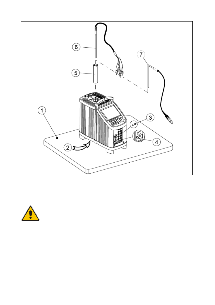
3.1.1 Setting up a dry-block calibrator
ig. 1a – This image shows the RTC-model
F
Follow the instructions below before using the calibrator (cf. fig. 1a)
Warning
Always position the calibrator to enable easy and quick
disconnection of the power source (mains inlet socket).
1. Place the calibrator on an even horizontal surface where you
intend to use it (pos. 1).
18 2018-03-13 128206 06
Page 20

Caution…
• The well
must
be clean before use.
flammable substances, etc.
2. Ensure a free supply of air to the internal fan located at the
• Do not use the instrument if the internal fan is out of
order.
bottom of the instrument (pos. 2)
The area around the calibrator should be free of draught, dirt,
3.
4. Check that the earth connection for the instrument is present
5.
6.
Check that the voltage setting, shown on the power control
switch (pos. 3), is identical to the mains voltage used.
and attach the cable below the power control switch (pos. 4).
Select an insertion tube (pos. 5) with a boring diameter
matching the sensor (pos. 6) to be calibrated. Ensure that
both the well and the insertion tube are clean. Insert the tube
into the well.
Place the sensor (pos. 6) and the reference sensor – if
available (pos. 7) in the insertion tube (pos. 5) as shown in fig.
a.
1
128206 06 2018-03-13 19
Page 21
3.1.2 Setting up a liquid bath calibrator (RTC-158/250 only)
silicone oil, if spilled.
10
11
9
6
l
i
O
5
4
3
1
7
2
8
Fig. 1b
ollow the instructions below before using the calibrator (cf. fig. 1b)
F
Warning
Always position the calibrator to enable easy and quick
disconnection of the power source (mains inlet socket).
1. Place the calibrator on an even horizontal surface where you
intend to use it. Place it in a way that will minimize the risk of
tilting (pos. 1). It is recommended to cover the surface with a
disposable cover in order to protect the surface against the
20 2018-03-13 128206 06
Page 22

It is also recommendable to have a sufficient amount of
adjusted to the actual job.
disposable paper towels within reach.
Caution…
2.
3.
• Do not use the instrument if the internal fan is out of
order. Ensure a free supply of air to the internal fan
located at the bottom of the instrument (pos. 2).
• The well must be clean before use.
The area around the calibrator should be free of draught, dirt,
flammable substances, etc.
Place the parts from the liquid bath kit in the well in the
following order:
• Bottom shield (pos. 3) – It is very important that the
bottom shield is placed in the well before any calibration
is attempted, as the bottom shield protects the well from
being damaged during calibration.
• Stirring magnet (pos. 4) – It is very important that the
stirring magnet is in place and spinning before any
calibration is attempted. The stirring magnet ensures
minimum temperature gradient in the fluid. The magnets
teflon cover will over time be worn down, leaving the
magnet flat on one side. This will reduce the spinning
ability. A magnet with a flat side must therefore be
replaced.
• Sensor basket (pos. 5) – It is very important to place
the sensor basket in the well, as it ensures that the
sensors encounter maximum temperature stability and
ensures that the stirring magnet is not blocked.
• Silicone oil (pos. 6) – Fill the well with oil according to
the tables of recommended oil volume listed in the
tables below. The recommended volumes must be
The sensor basket (pos. 4) is marked with an optimum
fluid level mark (100%). When filling the well with fluid and
placing the sensors, this mark must never be exceeded.
128206 06 2018-03-13 21
Page 23
RTC-250 A/B/C RTC-158 A/B/C
50 cSt oil
10 cSt oil
For recommended
For recommended
0°C - 50°C
50°C - 100°C
100°C - 150°C
150°C - 200°C
200°C - 250°C
100%
95%
90%
85%
80%
-20°C - 50°C
50°C - 100°C
100°C - 120°C
120°C - 155°C
100%
95%
90%
85%
Warning
• Do not handle hot fluid.
• Do not pour cold fluid into a hot well – it might cause an
explosion
• Do not pour water or any other fluids into a bath filled
with hot oil, because only a few drops of water might
cause a steam explosion, if poured into e.g. above 100°C
hot oil.
• If the fluid is heated beyond the flash point, it may
constitute a fire hazard.
• AMETEK Denmark A/S does not take any responsibility,
if the well is filled with other fluids than those
recommended.
If the fluid has caught fire, switch off the main power to prevent further
heating of the fluid. Flames are best extinguished by cowering the well
with a non-flammable lid.
Caution…
• Be careful not to overfill the well with oil.
The oil level rises several centimetres when the
temperature is rising to maximum. To stop the overflow
switch off the main power and the oil level will decent.
• Do not attempt to remove hot fluid with the liquid drainage
syringe, as it might melt.
4. Check that the voltage setting, shown on the power control
switch (pos. 7), is identical to the mains voltage used.
22 2018-03-13 128206 06
Page 24

5. Plug in the mains cable below the power control switch (pos.
section 4.6.
rises, to prevent o
verflow.
sensor.
8) and check that the earth connection is present. Switch on
the calibrator.
6. Start the stirring magnet by following the procedure in section
4.12.
Warning
Always set the “Max. SET-temperature” of the calibrator
according to the specified temperature range of the liquid.
The “Max. SET-temperature” must never exceed the flash
point or the boiling point of the liquid.
7. Select a SET-temperature according to the tables of
recommended oil volume by following the procedure in
8. Carefully monitor the oil level in the well, as the temperature
9. Place the calibration lid (pos. 9) onto the well. Holes with a
boring diameter matching the sensors to be calibrated must be
drilled into the lid before using it.
10. Place the sensor (pos. 10) and the reference sensor – if
Start the calibration of either the dry-block calibrator or the liquid bath
calibrator following the calibration procedure in this manual.
128206 06 2018-03-13 23
available (pos. 11) - to be calibrated vertically into the well. It
is recommended to use the optional support rod set for a
correct position during calibration.
Caution…
• The tip of the sensor should rest at the bottom of the
sensor basket for optimum results.
• Be careful not to submerge the handle or wire inlet of the
sensor-under-test in the fluid, as this might damage the
Page 25
3.2 During use
below 0°C/32°F
– they
might
create frostbite.
to the calibrator or
degrade the performance.
Caution – Hot surface
This symbol is engraved in the grid plate.
• Do not touch the grid plate, the well or the insertion
tube while the calibrator is heating up – they may be
very hot and cause burns.
• Do not touch the lid or the spill tray when the calibrator
is heating up – they may be very hot and cause burns
(liquid baths only).
• Do not touch the tip of the sensor when it is removed
from the insertion tube – it may be very hot and cause
burns.
• Do not touch the handle of the calibrator during use –
it may be very hot and cause burns.
• Do not remove the insert from the calibrator before the
insert has cooled down to less than 50°C/122°F.
Caution – Cold surface
• If the calibrator has reached a temperature below
0°C/32°F, ice crystals may form on the insertion tube
and on the well. This, in turn, may cause the material
surfaces to oxidize.
To prevent this from happening, the insertion tube and
the well must be dried. This is done by heating up the
calibrator to min. 100°C/212°F until all water left has
evaporated.
Remove the insulation plug while heating up.
It is very important that humidity in the well and
insertion tube is removed to prevent corrosion and frost
expansion damages.
• Do not touch the well or insertion tube when these are
Caution…(liquid baths only)
24 2018-03-13 128206 06
• Be careful to select the right fluid for the right task. Using
other than the recommended fluids might cause damage
Page 26

• It is vital that the stirring magnet is in place and spinning
before any calibration attempts. The spinning magnet
ensures optimum temperature homogeneity in the oil.
• It is strongly recommended to leave the lid on during
calibration. Calibration without the lid may affect the
temperature stability and homogeneity.
• When heated to high temperatures, the liquid bath
calibrator should be placed under a exhaust hood to
remove any vapors given off by the oil.
3.3 Programming intelligent sensors
Use the configuration software CON050 supplied with RTC/PTC to
program and to update calibration information in intelligent sensors.
For instructions read the software manual for CON050
.
3.4 Keyboard
The keys on the keyboard activate the following functions:
Keys Description RTC PTC
Full colour VGA display (main screen display
information – see section 3.5)
128206 06 2018-03-13 25
NUMERIC KEYS to select menu options
displayed in the horizontal and vertical menus
and to type in values
BACK KEY to cancel a selection/edit or
return to previous menu.
MENU KEY shows the vertical menu options
listed. Can be displayed all through the
process
DELETE KEY deletes previous character
X
X
X
X
X
X
X
Page 27

Keys
Description
RTC
PTC
in the desi
red direction
the
ENTER KEY
the cursor
ENTER KEY accepts selected options or
entered values. When a value is entered with
the ENTER KEY the cursor selects the next
value field in the list.
ARROW KEYS have different functions
depending on the mode of operation.
In navigation mode, they move the cursor in
the desired direction.
In edit mode they roll in the list of options or if
entering a number, the ARROW left and
ARROW right move the cursor one character
X
X
X
ACTION KEY opens and closes edit fields or
a menu button. The action key also accepts
the selected option or entered value.
ACTION KEY and ENTER KEY
ACTION KEY opens and closes edit fields or
a menu button. The action key also accepts
the selected option or entered value.
ENTER KEY accepts selected options or
entered values. When a value is entered with
X
X
26 2018-03-13 128206 06
Page 28

3.5 Main screen display
Description
RTC
PTC
Main screen display
The Main screen display is divided into four separate areas.
This image shows the RTC main screen display:
1
2
3
4
5
Fig. 2
Pos.
128206 06 2018-03-13 27
1 Heading: Informs you of the current menu
selected.
2 Setup field: Provides the bulk of setup data in
the menu. This data can be changed by moving
the cursor to the various fields.
3 Horizontal menu: Provides you with the
relevant menu options that can be selected at
the present point. Each option can be activated
either by selecting and activating the option – or
simply by pressing the numeric key that
corresponds to the option number.
X X
X X
X X
Page 29

Pos.
Description
RTC
PTC
the calibrator.
4 Readings: This reading line is always visible
and informs you of the current readings.
X X
5 Vertical menu: This menu can be activated
X X
throughout the entire calibration. The menu can
be switched on and off in all stages of operating
Main screen display information
The main screen gives an overview of the calibrator status and reads
out the most relevant readings. In the Sensor Setup menu (see section
4.10) these readings can be changed.
This image shows the RTC main screen.
Fig. 3
28 2018-03-13 128206 06
Page 30

Pos. Description RTC PTC
reference sensor.
X
X
control this value towards 0.00°C.
displayed as READ value.
1
Resistance of external reference sensor when
external reference sensor is selected as
TRUE. (Optional - PTC)
2
Stability indicator displays the status of the
True temperature stability.
3
True temperature reading. Can be either the
internal reference sensor or an external
X
X
X
X
X
X
4
Sensor under test value in ohm/mV/mA.
(Optional - PTC)
Sensor Under Test Stability indicator. If
5
Sensor under Test stability criteria is selected,
a symbol will indicate the stability of the
sensor under test as well as the True sensor.
SENSOR. Sensor Under Test value.
6
7 DLC sensor reading. Displays the measured
temperature load of the insert –if the load
compensation is active, the DLC system will
8 DLC compensation activated. The icon
indicates, that the Dynamic Load
Compensation function is active
9 READ value. The internal reference is always
10
11
12
SENSOR value always visible.
TRUE value always visible.
READ value always visible.
X
X
X
X
X
X
X X
X
X
X
X
X
X
13
14
15
16
17
128206 06 2018-03-13 29
SET reading always visible.
SET temperature.
Sensor Under Test Type.
Set follows True activated.
Reference Sensor Info.
X
X
X
X
X
X
X
X
X
X
Page 31

Pos. Description RTC PTC
warnings and errors.
18 WARNING/ERROR symbol. The yellow icon
indicates a warning. The red icon indicates an
error. When the error symbol is displayed the
calibration results cannot be saved. See the
reference manual for details concerning
19
20
Stirrer activated/speed indicator. The icon
indicates that the stirrer is activated and how
fast it is spinning (RTC-158/250 only).
Real Time Clock display.
X X
X
X
X
30 2018-03-13 128206 06
Page 32

3.6 Standard connections
Description
RTC
PTC
5 Device
:
USB 2.0 Device Port, 1 x USB B
X
X
Communication connections
This image shows the RTC-model.
2
11
4
3
S
O
H
5
E
C
I
V
E
D
T
E
C
I
V
E
D
T
S
O
H
Fig. 4
Pos.
1 SD-card: SD/MMC card slot X
2 Ethernet: Ethernet MAC 10/100 base-T, RJ45 X X
3 Sync.: Sync. Relay output, 3.5 mm Mini Jack X
4 Host: USB 2.0 Double Host Port, 2 x USB A X X
128206 06 2018-03-13 31
Page 33

3.7 Input modules (B and C versions only)
Warning
• The input terminals must NEVER be connected to
voltages exceeding 30V with reference to ground.
Description of sockets for external connections
This image shows the RTC-model.
Fig. 5
Pos. Description RTC PTC
1 Input for reference sensor (B and C versions) X X
2 Input for DLC sensor (B and C versions) X
32 2018-03-13 128206 06
Page 34

Pos. Description RTC PTC
3 Connection for thermostat switch test (B-
X X
version)
Note that this connection is for voltage free
switches
4
24V supply for active mA input (B-version) X X
Passive mA input (B-version) X X
5
6
Voltage input (B-version) X
7
Connection to chassis (earth/ground) (B-
X X
version)
8
TC connection for thermocouples (B-version) X X
9
Input for RTD sensor (2, 3 or 4 wire) (B-
X X
version)
One of the inputs either pos. 5, 6 (only RTC), 8 or 9 can be selected
displaying the “SENSOR” temperature in the Setup and pos. 1 can be
displayed as “TRUE” temperature.
Note: Only the sensor type, which is to be tested, should be connected
to the input panel.
3.8 Stability of temperature values
The stability of the TRUE and SENSOR temperatures are indicated by
the following messages:
• : ”Not stable": Indicates that the measured temperature is not
yet within the specified stability criteria.
• : Indicates "Time to stable": The temperature changes are
4:32
within the specified stability criteria (see chapter 8.0) and
states a time (in minutes and seconds) when the stable
situation can be achieved.
• : Indicates that the “stable” situation is achieved.
128206 06 2018-03-13 33
Page 35

4.0 Operating the Calibrator
The RTC main screen display
The PTC main screen display
4.1 Operating principle
The calibrator is operated using the horizontal and the vertical menu
list.
The NUMERIC keys (RTC-models only) are used for selecting and
activating the various menus and functions from both the horizontal
and vertical menu lists.
The (ACTION key) (RTC and PTC models) and (ENTER
key) (RTC models only) are also used for selecting and activating the
menus and functions and for accessing various parameters in setup
fields.
The (ARROW keys) (RTC and PTC models) are used to move
from menu item to menu item in the menu lists, to access various result
lists, to scroll through various lists and to access setup fields.
Note…
Please note that the keyboards of the RTC and PTC
instruments are different. Only the RTC-models have
NUMERIC keys and ENTER key.
Whenever the NUMERIC keys and ENTER key are
mentioned in this manual, the text is referring to the RTCmodels only.
34 2018-03-13 128206 06
Page 36

4.1.1 Horizontal Menu
key (RTC on
ly).
The horizontal menu options apply to the displayed screen. It is
dynamically giving the relevant choices during operation. Each menu
function can be activated in 2 ways:
1. Move the blue cursor with the ARROW key to mark
the menu button on the screen. Then press or to
activate the selection.
4.1.2 Vertical Menu
The vertical menu list can be called at any stage of operation making it
possible to jump to the desired menu.
This allows you to jump to the most used menu easily - no matter
where you are.
2. Whenever the menu is visible simply press the NUMERIC
128206 06 2018-03-13 35
Page 37

press the button again or (BACK).
(RTC only)
.
This menu always gives the same options, however at some points
some choices are not relevant and will therefore be shaded, i.e. you
can not set a temperature, when an Auto step procedure is running.
Each menu function can be activated in 2 ways.
Press the button to access the menu. To exit the menu,
1. Move the cursor with the ARROW keys or to mark
the menu field on the screen. Then press or to
activate the selection.
4.4.3 Parameter Fields
The setup menus have fields for parameter entries. When the setup is
entered, then focus will be on the horizontal menu, and the function
here can be activated.
2. When the menu is visible simply press the NUMERIC key
36 2018-03-13 128206 06
Page 38

parameter field.
Use the 4 ARROW keys to move between the parameter fields.
By pressing the ARROW UP key focus will move from the
horizontal menu to the parameter field area.
The parameter field area focus is indicated by
• The horizontal menu is now shaded
• The parameter field area has a blue frame (RTC only)
• The selected parameter field highlighted with a dark
blue color (RTC only)
• The selected parameter field is highlighted with a dark
grey colour (PTC only)
A parameter value is changed by:
C
°
128206 06 2018-03-13 37
• Pressing or to open the field for editing.
• A numeric field can be entered directly without opening
it first – simply enter the number (RTC only).
• Press one of the 2 ARROW keys or to move
between the numeric fields (PTC only).
• Enter a numeric field by pressing either or (PTC
only).
When the parameter is entered press one of the keys:
This enters the value and leaves the cursor on the
parameter field.
This enters the value and moves the cursor to the next
Page 39

4.4.4 Working with lists
When it is possible to choose between a number of data sets, the data
sets are presented in lists.
As an example access the Calibrator Setup menu from the
vertical menu and activate “Load/Save”
A list of instruments settings will be displayed.
38 2018-03-13 128206 06
Press ARROW UP to move the focus from the horizontal
menu to the list.
The selected data set in the list is now highlighted with a dark
blue color.
Page 40

from the memory into the active setup.
“Switch test” from the main menu and then activate “Results”.
Scrolling in the list is done using the ARROW UP key and
the ARROW DOWN key .
When the desired dataset in the list is highlighted press or
.
Now the horizontal menu will be in focus again and here you
are able to decide what to do with the chosen dataset.
Activate the desired function in the horizontal menu. In this
example the highlighted Instrument Settings will be loaded
Some lists have no horizontal menus and only one option
available.
As an example access the Switch test menu by selecting
128206 06 2018-03-13 39
Page 41

Scroll through the list using the ARROW UP key and the
Access the Set Temperature function by selecting “Set
Tem
perature “.
ARROW DOWN key and just press or to display
the result of the highlighted dataset.
4.5 Starting the calibrator
Switch on the calibrator using the power control switch. A start up
screen is displayed and then replaced with the main menu screen:
The functions in the horizontal menu are available using the soft keys
or the arrow keys on the keyboard (see description in section 3.4).
°C
4.6 Setting the temperature
40 2018-03-13 128206 06
°C
Page 42

when one of the automatic functions
is active.
Access the Calibration menu by selecting “Calibration” from
A Workorder List is displayed.
For RTC models
Use the NUMERIC keys to enter a new value, or or to
accept the value. When pressing the ACTION key or the
ENTER key the calibrator returns to the main menu screen.
For PTC models
Use the ARROW keys to enter a new value, and to
accept the value and return to the main menu screen. If
pressing the BACK key the calibrator returns to the main
menu screen without accepting the new value.
The Set temperature function can also be accessed using the
vertical menu (press ). Through this menu a new set point
value can be entered at any stage of the operation except
4.7 Calibration (optional - PTC)
This function enables you to perform automatic calibrations of different
temperature sensors. The calibration procedure is semi-automatic,
using parameters and settings, which are defined in workorders. These
workorders are created and edited using the "JOFRACAL" PC
program. Multiple calibrations can be performed using the same
workorder settings.
128206 06 2018-03-13 41
Note…
This Calibration function is for B versions only.
the main menu.
Page 43

me
nu.
4.7.1 Running a calibration
Run the selected workorder by activating “Run“. A new
calibration is started.
You can also chose to activate:
“View” – shows the setting of the workorder.
“Results” – shows the previous calibration results from this
workorder.
“Delete” – deletes the workorder setting and the results.
For operating the Results menu see section 4.7.2.
For operating the View menu see section 4.7.3.
For operating the Delete function see section 4.7.4.
To run the calibration, select “Run“ from the Workorder List
If the serial number of the reference sensor used for
calibration does not match the one specified in the workorder
the following message is displayed :
If you proceed, the connected reference sensor will be
documented along with the results.
If you do not wish this message to appear, the correct
reference sensor must be specified when the workorder is
edited using the “JOFRACAL” PC program.
Choose “YES” and press or if you want to proceed
with the calibration.
42 2018-03-13 128206 06
Page 44

the process.
A workorder S
23.50
The Parameter setup menu is displayed.
Note…
If the sensor under test is a thermocouple sensor and the
manual compensation mode is selected in work orders, a
cold junction temperature must be defined.
The parameters in the workorder can be edited.
Note…
• Only numeric data can be entered.
• The BACK key cancels a selection/edit or returning
to previous menu. The ESC key can be used throughout
128206 06 2018-03-13 43
Select “Next “ to proceed with the operation.
cenario is displayed, giving a graphical display
of the setup and sensor connections.
Start the calibration by selecting “Start Calibration”.
Page 45

The Calibration Running step 1 of 2 is started and the
temperature is heading towards step 1.
The following screen is displayed :
°C
When the temperature has reached the stable criteria, the
calibration data will be stored and the temperature goes
towards the next set temperature.
If the workorder contains manual reading during calibration,
you will be asked to enter the Sensor Under Test temperature
before that.
The following screen is displayed :
If manual readings are specified these will have to be entered
before next step starts.
Note…
The calibration can be stopped at any time by activating
“Stop”, but this will erase the calibration results.
44 2018-03-13 128206 06
Page 46

“View”
- To view the workorder settings.
During calibration several other functions are available:
“Result” - To view the calibration results (no editing is
possible).
“Pause” - To pause the calibration.
“Prev” - Force the calibration to jump a step backwards
to the previous calibration screen regardless of
the calibration stability.
“Next” - Force the calibration to jump a step forwards to
the next calibration screen regardless of the
calibration stability. This will leave the current
step without saving calibration results.
When the calibration has completed a green check is
shown on the screen and the Calibration Result follows
quickly hereafter.
Select “Save” to store the results in the calibrator
or
128206 06 2018-03-13 45
select “Discard” and press “Yes” to delete the calibration
results or “No” to return to the Calibration Result screen.
A full Calibration Result List can be viewed using the
instructions in section 4.7.2.
Page 47

4.7.2 Viewing calibration results
Access the Calibration Result function by selecting
A full Calibration Result List is displayed.
“Results” from the Workorder List menu.
Select a workorder to be displayed showing the calibration
details for the specific workorder.
The calibration results can be uploaded with the “JOFRACAL”
PC program. This enables you to print out the results on a
certificate.
Press to exit the Calibration Result List and return to the
Workorder List menu.
46 2018-03-13 128206 06
Page 48

4.7.3 Displaying calibration information
Access the Workorder Sensors menu by selecting “View”
A list of Workorder Notes is displayed.
Calibration information is defined within the work orders created on the
PC using "JOFRACAL".
from the Workorder List menu.
The Workorder Sensors menu is displayed.
This screen gives you an overview of the workorder sensor
setup including a summary of Notes, Scenario and Steps.
Each of these can be displayed in details.
Select “Notes” to access the Notes function.
The notes are information entered via the PC program, when
the workorder is created.
128206 06 2018-03-13 47
Press to exit the Workorder Notes screen.
Page 49

A Workorder Scenario is displayed.
A list of Temperature Steps is displayed.
Select “Scenario” to access the Scenario function.
The calibration set up is shown in a graphic format, and the
active sensor input is marked. The parameters for this setup
are defined in the work order created using the PC program.
Press to exit the Workorder Scenario screen.
Select “Steps” to access the Step function.
This function shows the pre-defined temperature steps for
the calibration.
Press to exit the Step function and return to the
Workorder Sensors menu.
48 2018-03-13 128206 06
Page 50

4.7.4 Deleting workorders
you want to exit the Delete function without deleting anything.
main menu.
It is possible to delete a workorder using the Delete function
from the Workorder List menu.
Select “Delete” to access the Delete function.
Press “Yes” if you want to delete your workorders and “No” if
Warning
If you choose to delete a workorder, the whole workorder
including the calibration results will be deleted.
Press to exit the Workorder List menu and return to the
128206 06 2018-03-13 49
Page 51

4.8 Switch test menu
Access the Switch test menu by selecting “Switch test” from
A Switch test setup menu is displayed.
Note…
Switch test automatically locates the switch temperatures of a
thermostat.
Three parameters are required:
• Start temperature (T1)
• End temperature (T2)
• Rate of change in temperature (slope rate).
Hysteresis of a thermostat can also be determined here.
4.8.1 Running a switch test
This Switch test function is for B versions only.
the main menu.
The small graph illustrates the current T1, T2 and hysteresis
selections. Note that T1 can be greater than T2.
50 2018-03-13 128206 06
Page 52

Access the setup field to edit the parameters:
connected to the switch input (see page
på side 33
, pos.
4).
screen.
• T
• T
• Hysteresis - to determine hysteresis, toggle between
• Slope rate - The permitted range is 0.1 - 9.9°C/min. /
Note…
the slope rate should be set so that the
thermostat sensor can follow the temperature in the
calibrator's well.
- first set temperature
1
second set temperature
2 -
"Yes" (a two-way-temperature measurement) and "No"
(a one-way-temperature measurement).
0.2 - 17.8°F/min.
Press to exit the setup function and return to the Switch
test setup menu.
Before starting the switch test ensure that the switch is
Select “Start” to start the switch test.
The Switch Test is now in progress.
While the switch test is in progress, 2 options are available:
“Result” – displaying the current switch test results.
“Stop” – stopping the switch test. Press “Yes” to stop the
switch test and “No” to return to the Switch Test
°C
128206 06 2018-03-13 51
Page 53

Access the Switch Test Result List by selecting “Result” from
4.8.2 Showing switch test results
Two types of switch test results are available:
• Results during a switch test.
• Results of a finished switch test.
Results during a switch test
the Switch Test menu.
Finished switch test results
At the end of a switch test the results are displayed. These show the
temperature when the thermostat has closed and the temperature
when it has opened – whichever comes first. The difference between
these 2 temperatures is calculated as the hysteresis.
52 2018-03-13 128206 06
This shows the results that are currently available. These
results change as the test progresses.
Press to return to the switch test.
Select “Save” to save the results storing them in the
calibrator’s memory.
Page 54

A hysteresis result is only measured when hysteresis is set
Select “Discard” to delete the results from the screen.
Note…
to “Yes”.
You will then automatically return to the Switchtest setup
menu.
If no change in the switch position is registered during the
test a red cross will be displayed in the Result list instead of
a green check .
128206 06 2018-03-13 53
Delete the result by selecting “Discard” or save the result by
selecting “Save”.
Page 55

To view stored switch test results
Access the Switch Test
Access the Auto Step Setup menu by selecting “Autostep”
from the Switch test setup menu.
Select a test result to be displayed.
Result List by selecting “Results”
Press twice to return to the Switch test setup menu.
4.9 Auto step menu
Auto step is used to step automatically between a range of different
calibration temperatures.
4.9.1 Running an Auto step calibration
from the main menu.
54 2018-03-13 128206 06
Page 56

Access the Auto Step Setup
menu.
Access
Auto Step Setup menu.
settings as described in
section 4.10
– Sensor Setup menu.
The Auto Step Setup menu is displayed.
to edit the parameters:
• No of steps: the number of temperature steps per
direction (T1Tx) can be set using integers from 1 – 20.
When a Two-way mode is selected, the same number of
steps are used for the second direction (T
• Mode: toggle between “One-way” and “Two-way”.
• Hold time: defines the time (in minutes) the temperature
is maintained (after it is stable) for each step.
• T step values: must be set within the sensors permitted
range.
xT1
).
128206 06 2018-03-13 55
Press to exit the editor and return to the Auto Step setup
the Sensor setup menu by selecting “Next” from the
The Sensor setup menu is displayed. In this menu you have
the opportunity to check and if necessary change the
23.00
Page 57

An Auto Step Running step screen is displayed.
stability.
Select “Start” to start the Auto Step calibration.
°C
While the step test is in progress, several functions are
available:
“Result” - To review the Auto Step results (no editing is
possible).
“Stop” - To stop the Auto Step test.
“Pause” - To pause the test.
“Prev” - Force the test to jump a step backwards to the
previous running step regardless of the step’s
stability.
“Next” - Force the test to jump a step forwards to the
next running step regardless of the step’s
When the Auto Step test is complete the results are
displayed.
Select “Save” to save the results storing them in the
calibrator’s memory.
56 2018-03-13 128206 06
Page 58

The calibrator then returns to the Auto Step Setup menu.
Access the Auto Step Result List by selecting “Results” from
4.9.2 Auto Step test results
At the end of an Auto Step test the results are displayed and stored in
the calibrators memory.
The measured TRUE and SENSOR temperatures for each step are
displayed.
To view stored Auto step test results
Select “Discard” to delete the results from the screen.
the Auto Step Setup menu.
The Auto Step Result List is displayed.
Select an auto step result to be displayed.
Press twice to return to the Auto Step Setup menu.
128206 06 2018-03-13 57
Page 59

4.10 Sensor Setup menu
Activate “Sensor Setup”
4.10.1 Setting the additional stability time (A version)
The Sensor Setup can be entered through the vertical menu
(press )
The Sensor Setup can also be edited immediately before
running the Auto step (section 4.9.1) or when starting a
switch test.
.
Set the additional stability time by pressing and the
NUMERIC keys (RTC only) / ARROW keys (PTC only).
Stability time can be set (in minutes) using integers from
0 – 99.
23.00
58 2018-03-13 128206 06
Page 60

4.10.2 Setting the parameters for TRUE – reference sensor (B
and C versions only)
Sensor type:
Internal reference source.
The internal reference sensor will be displayed as the TRUE
value on the main screen.
The calibrator has a set of internal stability criteria it shall
meet before stability is indicated.
may be set beyond the internal stability criteria.
Set the additional stability time by pressing and the
NUMERIC keys (RTC only) / ARROW keys (PTC only).
Stability time can be set (in minutes) using integers from
0 – 99.
Additional stability time
External reference source
The TRUE value on the main screen will be read from the
Intelligent Reference Sensor connected to the REF. INPUT
on the front panel (see section 3.7 pos. 1). The calibrator
automatically reads the calibration data and serial number of
the Sensor.
Convert to temperature:
• “yes” sets the readout of the External reference as a
temperature.
• “no” sets the readout of the External reference in Ω
values.
128206 06 2018-03-13 59
Page 61

parameters or the Sensor under test parameters.
SET follows TRUE:
This function enables you to reach the TRUE temperature
measured by the External reference sensor.
Note…
t
hat when “yes” is selected, the calibrator will control the
temperature to the TRUE temperature. This means that it
could take longer time before the calibrator indicates
stability.
The “SET follows TRUE” function is indicated with the
symbol at the TRUE reading in the main display.
Note…
SET follows TRUE is only relevant when the External
reference sensor is displayed in temperature units.
Stability tolerance:
The tolerance should be set low enough to utilize the good
temperature stability of the calibrator – however a low value
also gives a longer time to be stable.
Stability time:
Stability time can be set from 1 – 99 minutes.
When the TRUE temperature has reached the specified
Stability tolerance during the specified Stability time, then the
stability indicator in the main screen will turn green.
Press to accept the new setting(s) and return to the
Sensor setup menu or continue to edit the DLC sensor
60 2018-03-13 128206 06
Page 62

4.10.3 Setting the parameters for DLC– dynamic load
it must be enabled.
parameters or the Sensor under test parameters.
• None (no sensor connected)
the following :
compensation – (RTC, B and C versions only)
4.10.4 Setting the parameters for SUT– Sensor under test (B
The DLC value on the main screen will be read from the
Intelligent Load Sensor as soon as it is connected to the
DLC INPUT on the front panel (see section 3.7 pos. 2). The
calibrator automatically reads the calibration data and serial
number of the Sensor.
However if the Dynamic Load Compensation shall be active,
Use load compensation:
The active “DLC” function is indicated with the symbol at
the DLC reading in the main display.
Note…
always use external reference sensor when calibrating with
the DLC-function activated for specified accuracy.
Press to accept the new setting(s) and return to the
Sensor setup menu or continue to edit the reference sensor
versions only)
128206 06 2018-03-13 61
Sensor type:
Choose between :
• thermocouple sensors (µV)
• voltage sensors (V) (RTC only)
• current sensors (mA)
• RTD sensors (resistance temp. detector (Ω))
Select a sensor.
The selected sensor and its list of parameters are now
displayed. The various settings can be edited as described in
Page 63

only other parameter which can be altered.
)385, *P50(90)385, P100(90)385,
corresponding temperature span can be set here.
Convert to temperature:
(using thermocouple, voltage, current and RTD)
• “yes” – the inputs are converted to temperatures.
• “no” – no conversion is made.
When “no” has been selected the type of model is the
Model:
(using thermocouple and RTD)
Toggle between the models; K, L, N, R, S, T, U, B, E and J
(thermocouple) or *P10(90
*P200(90)385,*P500(90)385, P1000(90)385, *P50(90)391,
P100(90)391, P100(90)392, *Pt-100 MILL, *YSI-400,
H120(90)672, *M100(90)428… and *M50(90)428 (RTD).
* Optional – PTC
Cold junction compensation:
(using thermocouple)
• “auto” – when the automatic mode is selected, the
calibrator measures the temperature in the T/C
connector and uses this for the cold junction
compensation of the thermocouple.
• “manual” – to define a manual temperature for cold
junction compensation. Can be used when an external
cold junction temperature can be established.
Cold junction temperature:
(using thermocouple)
When “manual” Cold junction compensation has been
selected the temperature for cold junction can be set using
the NUMERIC keys (RTC only) / ARROW keys (PTC only).
Voltage(V) and temperature(T) span (RTC only):
(using voltage)
The minimum and the maximum of the voltage and the
62 2018-03-13 128206 06
Page 64

and/or the temperature.
only)
to set the value of the current and/or the temperature.
(TRUE) temperature only.
Use the NUMERIC keys to set the value of the voltage
Current(C) and temperature(T) span:
(using current)
The minimum and the maximum of the current and the
corresponding temperature span can be set here.
Use the NUMERIC keys (RTC only) / ARROW keys (PTC
Number of wires:
(using RTD)
The number of wires used for the sensor under test can be
selected here.
Choose between 2, 3 or 4 wires.
Use stability criteria:
(using thermocouple, voltage (RTC only), current and RTD)
Beside the stability check on the Reference sensor, it is also
possible to ensure that the Sensor Under Test (SENSOR) is
stable before the temperature is indicated as stable.
• “yes” – Stability will be checked on both Reference
sensor (TRUE) temperature and Sensor Under Test
(SENSOR) temperature.
• “no” – Stability will be checked on Reference sensor
128206 06 2018-03-13 63
Stability tolerance:
(using thermocouple, voltage (RTC only), current and RTD)
Enter the Stability tolerance (temperature) by pressing the
NUMERIC keys (RTC only) / ARROW keys (PTC only).
The expected performance of the Sensor Under Test should
be considered before setting the tolerance.
Page 65

Stability time:
(using thermocouple, voltage (RTC only), current and RTD)
Set the Stability time by pressing the NUMERIC keys (RTC
only) / ARROW keys (PTC only). Stability time can be set
from 1 – 99 minutes.
4.10.5 Viewing the Reference and DLC data (B and C versions
only)
The calibration data of the Intelligent Reference sensor and
the intelligent DLC sensor (RTC only) can be viewed using
the Reference Info function or the DLC Info function (RTC
only) from the Sensor setup menu.
View the Reference Info box by selecting “Reference
Info”.
The Reference Info box is displayed.
Press to return to the Sensor setup menu.
View the DLC Info box by selecting “DLC Info” (RTC only).
64 2018-03-13 128206 06
Page 66

Activate “Calibrator Setup”
The DLC Info box is displayed.
Press to return to the Sensor setup menu.
4.11 Calibrator Setup menu
4.11.1 Setting the temperature parameters
The Calibration Setup can be edited through the vertical
menu (press ).
.
128206 06 2018-03-13 65
Temperature unit:
Choose between:
• °C (Celsius)
• °F (Fahrenheit)
• K (Kelvin)
Min SET temp / Max SET temp:
Enter the access code to get access to the editor.
Use the NUMERIC keys (RTC only) / ARROW keys (PTC
only) to set the Min/Max SET temperature in Celsius,
Fahrenheit or Kelvin.
Page 67

Note…
a few seconds allowing you to continue.
The Enter Access Code box is displayed every time you try
to access the Min/Max SET temp parameters. Type in your
access code and continue.
Access code:
e protected by an access code:
• Resetting the calibrator to Factory default settings.
• Setting the Min/Max SET Temperature.
• Editing the Access code while it is enabled.
Press or to access the Access code function.
Use the NUMERIC keys (RTC only) / ARROW keys (PTC
only) to type in a value from 0000 to 9999. Use all 4 digits.
Typing 0000 disables the Access code function.
The access code is accepted showing a green check for
Caution…
If you choose to let your access code consist of only 1, 2 or
3 digits you must enter the access code with 0 followed by
the chosen value.
Example:
The access code 12 is selected.
Type in 0012 in the Enter Access Code box
66 2018-03-13 128206 06
Page 68

Accept the new setting (empty box).
access code.
reading will not be displayed on the main screen.
Note…
The access code can be deleted allowing you to change the
Min/Max SET temperature without having to enter the
access code.
Press or to access the Access code function.
Type in your access code.
No new value is entered.
It is now possible to enter the editor without using the
4.11.2 Setting the temperature resolution
Choose between :
• SET
• READ
• TRUE
• SENSOR
Choose between the resolutions:
• 0.001 (RTC only)
• 0.01
• 0.1
• 1
SENSOR visible:
Choose between :
• Visible
• Hidden
If the Hidden option is chosen the Sensor Under Test
128206 06 2018-03-13 67
Page 69

4.11.3 Setting the sound, volume and operating mode
4.11.4 Setting calibration interval
Sound:
Choose between :
• On
• Off
Enables the calibrator to make a sound during operation.
Volume:
The volume of the sound can be adjusted from 0 – 100%.
Operating mode (RTC only):
Choose between :
• Fast
• Silent
“Fast” – the fan operates in a fast mode giving the best
performance of cooling.
“Silent” – the fan operates in a silent mode reducing the
noise. Using this option the cooling process is
made a little slower and the calibrator might not
be able to reach the specified minimum
temperature.
4.11.5 Changing the date and time
68 2018-03-13 128206 06
Sets the required recalibration interval for the calibrator.
Choose a value between 1 month and 99 months.
Date:
Use the NUMERIC keys (RTC only) / ARROW keys (PTC
only) to enter a new date.
Page 70

The date can only be entered using the format yyyy-mm-dd.
only)
to enter a new time using the format
hh.mm.
Access the
The Instrument Settings are displayed.
When entering the date with different format, the text will
disappear when you try to accept the setting.
4.11.6 Choosing a language (optional)
4.11.7 Saving a setup
Saving a setup saves parameters in the Setup menu.
Time:
The calibrator is set up with a default time (present time).
Use the NUMERIC keys (RTC only) / ARROW keys (PTC
Time Zone:
The relevant time zone is selected from a list of various
zones.
The calibrator is set up with a default language - English.
Instrument Settings menu by selecting
“Load/Save” from the Calibrator Setup menu.
128206 06 2018-03-13 69
Select a register number to be used for saving.
The setup will be saved with the selected register number.
Page 71

Note…
In the Calibrator Setup the following parameters will not be
saved:
• Min SET temp
• Max SET temp
• SENSOR visible
4.11.8 Loading a setup
Loading a setup causes the setup parameters to be overwritten.
You can save up to 10 setups.
When the setup is saved the parameters are visible in the
right side of the screen.
Select a setup from the list to be loaded.
The selected setup will be loaded into the calibrator’s
memory.
4.11.9 Resetting the instrument setup to factory defaults
Resetting to the factory default settings changes the active setup to the
initial settings.
70 2018-03-13 128206 06
Press to return to the Calibrator setup menu.
Page 72

4.11.10 Network Configuration (for service use only)
Access
The Network Configuration screen is displayed.
the Network Configuration function by selecting
“Network” from the Calibration Setup menu.
When DHCP is set to Enabled, the IP address will be
updated when leaving the network menu.
When DHCP is disabled, you can configure the IP-settings
manually using the NUMERIC keys (RTC only) / ARROW
keys (PTC only).
128206 06 2018-03-13 71
Page 73

4.12 Selecting the stirrer speed (RTC-158/250
only)
The Sensor Setup can be entered through the vertical menu
(press )
Use the ARROW keys to select “Stirrer Speed”.
Use the NUMERIC keys to enter a value, or or to
accept the value. When pressing the ACTION key or the
ENTER key the calibrator returns to the main menu screen.
Select a speed setting between 0 and 100.
The normal setting is between 30 and 40.
When using the RTC-158/250 A/B/C with a dry block kit the
stirrer speed must be set to 0.
The DLC will be disabled when the stirrer is started
72 2018-03-13 128206 06
Page 74

Caution…
select a speed setting lower than the previous.
A status summary of the sensors setting and stability
If the speed level chosen is too high, the magnet will fall off
making a rattling sound and there will be no stirring in the
fluid. With no stirring of the fluid, temperature gradients will
emerge in the bath, which will again affect the result of the
calibration.
To reconnect the magnet, set the speed level to 0 and
Press or to accept the value and return to the
setup menu.
4.13 Information Screen
Information about the status can be viewed using the Info
function from the vertical menu (press ).
information is displayed.
If a warning or an error has occurred, it will be listed on the
information screen.
Press to exit the Info function.
128206 06 2018-03-13 73
Page 75

4.14 About the calibrator
About function from the vertical menu (press ).
Information about the calibrator can be viewed using the
Press to exit the About function.
74 2018-03-13 128206 06
Page 76

5.0 Setting the mains voltage and
replacing the main fuses
This image shows the RTC-model
Warning
• The calibrator must be switched off before any attempt
to service the instrument is made. There are no user
serviceable parts inside the calibrator.
• The fuse box must not be removed from the power
control switch until the mains cable has been
disconnected.
• The two main fuses must have the specified current and
voltage rating and be of the specified type. The use of
makeshift fuses and the short-circuiting of fuse holders
are prohibited and may cause a hazard.
4
3
2
4
1
Fig. 6
1
128206 06 2018-03-13 75
Locate the main fuses in the fuse box in the power control
switch and check the voltage of the power control switch
(on/off switch (230V/115V)). If the voltage of the power
control switch differs from the line voltage, you must adjust
the voltage of the power control switch.
Page 77

2 Open the lid of the fuse box using a screwdriver.
3
4
Remove the fuse box.
Replace the fuses. The new fuses must be identical and
should correspond to the line voltage.
• RTC-156/157/158/159/187,
PTC-125/155 : 115V 8AT = 127211
230V, 4AT = 127210
• RTC-250/700, PTC-350/425/660: 115V, 10AF = 60B302
230V, 5AF = 127573
Slide the fuse box into place with the correct voltage turning
upwards.
If the fuses blow immediately after you have replaced them,
the calibrator should be returned to the manufacturer for
service.
76 2018-03-13 128206 06
Page 78

6.0 After use
tube may
get stuck if this is allowed to happen.
6.1 Storing and transporting the calibrators
Caution…
The following guidelines should always be observed when
storing and transporting the calibrators. This will ensure that
the instruments and the sensors remain in good working
order.
Warning (all heating dry-block models)
• Never leave hot insertion tubes that have been removed
from the calibrator unsupervised – they may constitute a
fire hazard or personal injury.
If you intend to store the calibrator in the optional
aluminium carrying case after use, you must ensure that
the instrument has cooled to a temperature below
100°C/212°F before placing it in the carrying case.
• Never place a hot insertion tube in the optional carrying
case.
Caution…
The insertion tube must always be removed from the
calibrator after use.
The humidity in the air may cause oxidation on the insertion
tube inside the instrument. There is a risk that the insertion
(all dry-block models)
Below 0°C/32°F
(applies only to the RTC-156/157/158/159/187, PTC125/155 A/B/C models)
• If the calibrator has reached a temperature below
0°C/32°F, ice crystals may form on the insertion tube
and on the well. This, in turn, may cause the material
surfaces to oxidize.
To prevent this from happening, the insertion tube and
128206 06 2018-03-13 77
Page 79

the well must be dried. This is done by heating up the
deep frozen
– they
might
create frostbite.
calibrator to min. 100°C/212°F until all water left has
evaporated.
Remove the insulation plug while heating up.
It is very important that humidity in the well and insertion
tube is removed to prevent corrosion and frost
expansion damages.
• Do not touch the well or insertion tube when these are
6.2 Handling the dry-block calibrator
The following guidelines must be observed before the insertion tube
is removed and the instrument switched off:
Caution – Hot surface
Do not remove the insertion tube from the calibrator before
the insertion tube has cooled down to less than 50°C/122°F
1. If the calibrator has been heated to temperatures
than above 50°C/122°F, you must wait until the instrument
reaches a temperature below 50°C/122°F before
you switch it off.
2. If the calibrator has reached a temperature below 0°C/32°F, it
should be heated to a temperature of 100°C/212°F (applies only to
the RTC-156/157/158/159/187, PTC-125/155 A/B/C models).
3. Remove the insulation plug while heating up.
4. Switch off the calibrator using the power control switch.
Note that the calibration procedure may be interrupted at any time
using the power control switch. Turning off the calibrator during the
calibration process will not damage either the instrument or the
sensor.
5. Remove the insertion tube from the calibrator using the tool
supplied with the instrument.
6. Optional: Store the calibrator in its protective, aluminium carrying
case.
78 2018-03-13 128206 06
Page 80

6.3 Handling the liquid-bath calibrator (RTC-
158/250 only)
Warning
Always remove the liquid from the calibrator before
transportation.
It is not recommendable to leave the fluid in the well for long-term
storage. The best way to store the fluid is in its original airtight
container.
It is recommended to remove the oil from the well before transportation
of the calibrator. It is, however, possible to move the liquid bath
calibrator by hand, when it is filled with fluids.
The transportation lid is used to reduce the risk of spilling.
As the lid is not completely fluid tight it is advisable to emptying the well
completely before any transportation is attempted.
The following guidelines must be observed before emptying the well :
Caution – Hot surface
• Do not handle hot fluid.
• Do not attempt to remove hot fluid with the liquid drainage
tube, as it might melt.
• Do not leave any fluid (silicone oil) in the spill tray.
• Do not touch the items removed from the well – they may
be very hot and cause burns.
• Never leave hot items, which have been removed from the
well, unsupervised – they may constitute a fire hazard or
personal injury.
1. Switch off the calibrator using the power control switch.
2. Before handling the fluid, it must be cooled down to a temperature
close to ambient.
3. Remove the sensor basket and clean it with disposable paper
towels.
128206 06 2018-03-13 79
Page 81

4. Remove the stirring magnet using the stirring magnet remover
supplied and clean it with disposable paper towels.
5. Empty the well using the liquid drainage tube supplied. Tilting the
calibrator is not recommendable, as it increases the risk of
splashing oil all over the test area.
Caution…
Avoid getting silicone oil on the clothes. It is impossible to
wash off.
6. Any remaining oil in the well is cleaned up using disposable paper
towels. It is recommendable to use the optional cleaning oil when
cleaning the well.
Warning
• REMEMBER, wear goggles when using the cleaning oil.
• Do not inhale vapours. Proper ventilation must be used.
• Product information on cleaning oil must be carefully
investigated before use.
80 2018-03-13 128206 06
Page 82

AMETEK Sensors, Test & Calibration
A busine ss unit of AME TEK Measur ement &
Calibration Technologies Division offering the
followi ng industr y leading bra nds for test an d
Portable dry-block calibrators, precision
therm ometers and l iquid baths. Temperature
Conveni ent electr onic systems r anging from
-25 mbar to 100 0 bar - fully tem perature -
compensated for problem-free and accurate
Process signal mea surement a nd simulation for
easy control loop calibration an d measurem ent
Pneumatic floating-ball or hydraulic piston dead
weight te sters with ac curacies to 0 .015% of
readin g. Pressure g enerators delivering u p to
Digital pressure gauges and ca librators t hat are
accurate, easy-to-use and relia ble. Design ed for
use in the h arshest e nvironment s; most products
Materials testing machines and software that
guara ntees exper t material s testing solu tions.
Also covering Texture An alysers to pe rform rap id,
gener al food testing and detailed texture ana lysis
on a diver se range of foo ds and cosme tics.
Allows measurement and charac terizatio n of
moisture-sensitive PET polymers and polymer
The han d held force ga uges and moto rized
tester s have earned t heir reputa tion for quality,
reliab ility and ac curacy and th ey represen t the de
facto standard for force measurement.
Hardness testers, durometers, optical systems
and sof tware for data acquisiti on and analy sis.
calibration instrumentation.
JOFRA Calibration Instruments
Temperature Calibrators
sensors for industrial and marine use.
M&G Deadweight Testers & P umps
carr y an IS, IP67 and D NV rating.
Davenport Polymer Test Equipment
Chatillon Force Measurement
Pressure Calibrators
field use.
Signal Instruments
tasks.
1,000 bar.
Crystal Pressure
Lloyd Materials Testing
densit y.
Newage Hardness Testing
www.ametekcalibration.com
United Kingdom
Tel +44 (0)1243 833 302
caluk.sales@ametek.com
France
Tel +33 (0)1 30 68 89 40
general.lloyd-instruments@ametek.fr
Germany
Tel +49 (0)2159 9136 510
info.mct-de@ametek.de
Denmark
Tel +45 4816 8000
jofra@ametek.com
Information in this document is subject to change without notice. ©2017, by AMETEK, Inc., www.ametek.com. All rights reserved.
USA
Florida
Tel +1 (800) 527 9999
cal.info@ametek.com
California
Tel +1 (800) 444 1850
crystal@ametek.com
India
Tel +91 22 2836 4750
jofra@ametek.com
Singapore
Tel +65 6484 2388
jofra@ametek.com
China
Shanghai
Tel +86 21 5868 5111
Beijing
Tel +86 10 8526 2111
jofra.sales@ametek.com.cn
 Loading...