

Page 1

BPS / Mx / RS Series
SCPI Programming Manual
(Including MX Series I / Series II)
7003-961 Rev AA www.programmablepower.com
Page 2

AMETEK Programmable Power BPS / MX / RS Series SCPI Programming Manual
SCPI Programming Reference Manual
• BPS Series AC Power Systems MX Series AC/DC Power Systems
• Mx Series AC/DC Power Systems
• RS Series AC/DC Power Systems
2 Manual P/N 7003-961 Rev AA
Page 3

BPS / MX / RS Series SCPI Programming Manual AMETEK Programmable Power
About AMETEK
AMETEK Programmable Power, Inc., a Division of AMETEK, Inc., is a global leader in the design
and manufacture of precision, programmable power supplies for R&D, test and measurement,
process control, power bus simulation and power conditioning applications across diverse industrial
segments. From bench top supplies to rack-mounted industrial power subsystems, AMETEK
Programmable Power is the proud manufacturer of Elgar, Sorensen, California Instruments and
Power Ten brand power supplies.
AMETEK, Inc. is a leading global manufacturer of electronic instruments and electromechanical
devices with annualized sales of $3.3 billion. The Company has over 11,000 colleagues working at
more than 80 manufacturing facilities and more than 80 sales and service centers in the United
States and around the world.
Trademarks
AMETEK is a registered trademark of AMETEK, Inc. California Instruments is a trademark owned by
AMETEK, Inc. Other trademarks, registered trademarks, and product names are the property of their
respective owners and are used herein for identification purposes only.
Notice of Copyright
BPS / MX / RS Series Programming Manual
rights reserved.
© 2003-2013 AMETEK Programmable Power, Inc. All
Exclusion for Documentation
UNLESS SPECIFICALLY AGREED TO IN WRITING, AMETEK PROGRAMMABLE POWER, INC. (“AMETEK”):
(a) MAKES NO WARRANTY AS TO THE ACCURACY, SUFFICIENCY OR SUITABILITY OF ANY TECHNICAL OR
OTHER INFORMATION PROVIDED IN ITS MANUALS OR OTHER DOCUMENTATION.
(b) ASSUMES NO RESPONSIBILITY OR LIABILITY FOR LOSSES, DAMAGES, COSTS OR EXPENSES, WHETHER
SPECIAL, DIRECT, INDIRECT, CONSEQUENTIAL OR INCIDENTAL, WHICH MIGHT ARISE OUT OF THE USE
OF SUCH INFORMATION. THE USE OF ANY SUCH INFORMATION WILL BE ENTIRELY AT THE USER’S RISK,
AND
(c) REMINDS YOU THAT IF THIS MANUAL IS IN ANY LANGUAGE OTHER THAN ENGLISH, ALTHOUGH STEPS
HAVE BEEN TAKEN TO MAINTAIN THE ACCURACY OF THE TRANSLATION, THE ACCURACY CANNOT BE
GUARANTEED. APPROVED AMETEK CONTENT IS CONTAINED WITH THE ENGLISH LANGUAGE VERSION,
WHICH IS POSTED AT WWW.PROGRAMMABLEPOWER.COM.
Date and Revision
June 2013 - Revision AA
Part Number
7003-961
Contact Information
Telephone: 800 733 5427 (toll free in North America)
858 450 0085 (direct)
Fax: 858 458 0267
Email: sales@programmablepower.com
service@programmablepower.com
Web: www.programmablepower.com
Manual P/N 7003-961 Rev. AA 3
Page 4
AMETEK Programmable Power BPS / MX / RS Series SCPI Programming Manual
Important Safety Instructions
Before applying power to the system, verify that your product is configured properly for your
particular application.
WARNING
WARNING
Only qualified personnel who deal with attendant hazards in power supplies, are allowed to perform
installation and servicing.
Ensure that the AC power line ground is connected properly to the Power Rack input connector or
chassis. Similarly, other power ground lines including those to application and maintenance equipment
must be grounded properly for both personnel and equipment safety.
Always ensure that facility AC input power is de-energized prior to connecting or disconnecting any
cable.
In normal operation, the operator does not have access to hazardous voltages within the chassis.
However, depending on the user’s application configuration, HIGH VOLTAGES HAZARDOUS TO
HUMAN SAFETY may be normally generated on the output terminals. The customer/user must
ensure that the output power lines are labeled properly as to the safety hazards and that any
inadvertent contact with hazardous voltages is eliminated.
Guard against risks of electrical shock during open cover checks by not touching any portion of the
electrical circuits. Even when power is off, capacitors may retain an electrical charge. Use safety
glasses during open cover checks to avoid personal injury by any sudden component failure.
Neither AMETEK Programmable Power Inc., San Diego, California, USA, nor any of the subsidiary
sales organizations can accept any responsibility for personnel, material or inconsequential injury, loss
or damage that results from improper use of the equipment and accessories.
Hazardous voltages may be present when covers are removed. Qualified
personnel must use extreme caution when servicing this equipment.
Circuit boards, test points, and output voltages also may be floating above
(below) chassis ground.
The equipment used contains ESD sensitive parts. When installing
equipment, follow ESD Safety Procedures. Electrostatic discharges might
cause damage to the equipment.
4 Manual P/N 7003-961 Rev AA
Page 5
BPS / MX / RS Series SCPI Programming Manual AMETEK Programmable Power
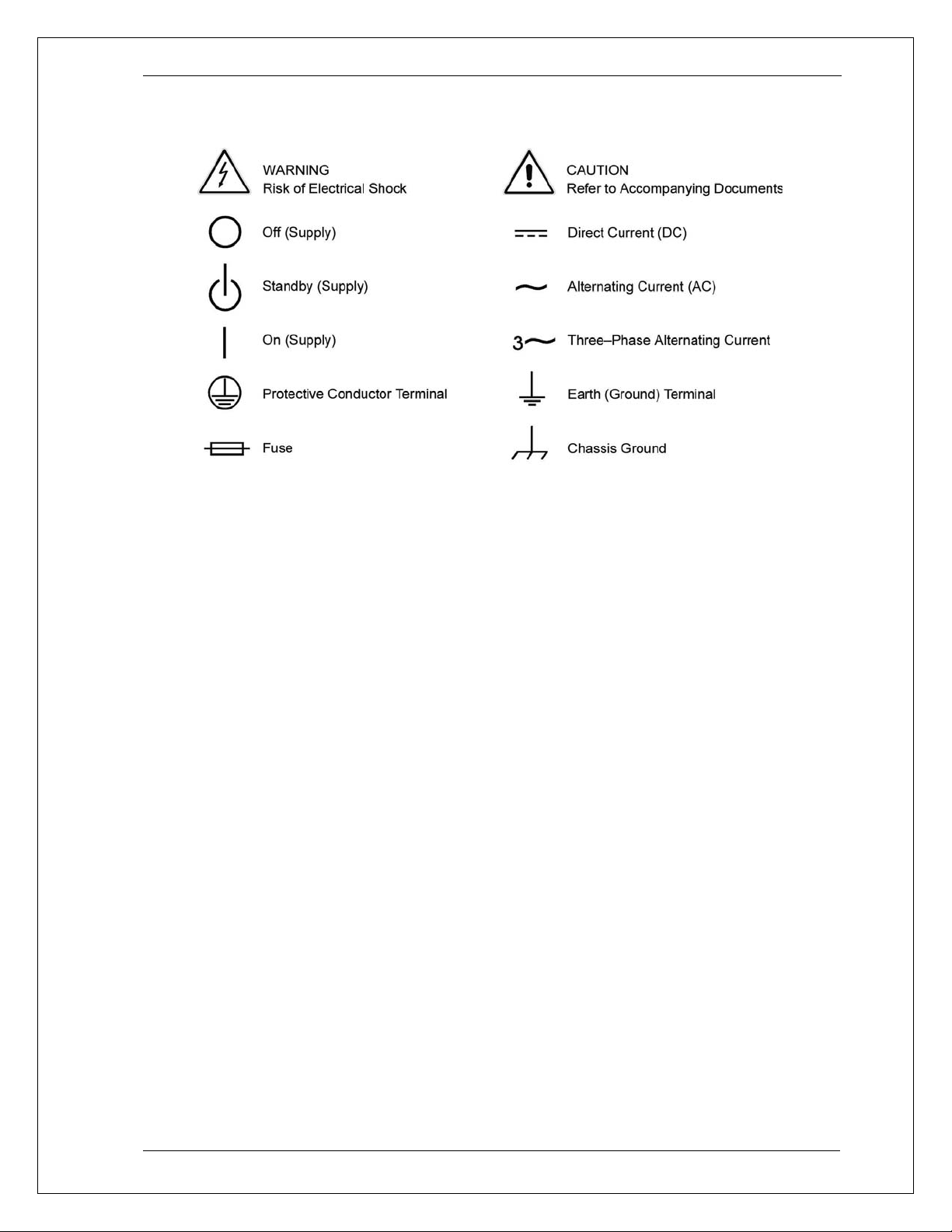
SAFETY SYMBOLS
Manual P/N 7003-961 Rev. AA 5
Page 6

AMETEK Programmable Power BPS / MX / RS Series SCPI Programming Manual
Product Family: BPS / MX / RS Series AC Power Source
Warranty Period: 1 Year
WARRANTY TERMS
AMETEK Programmable Power, Inc. (“AMETEK”), provides this written warranty covering the
Product stated above, and if the Buyer discovers and notifies AMETEK in writing of any defect in
material or workmanship within the applicable warranty period stated above, then AMETEK may, at
its option: repair or replace the Product; or issue a credit note for the defective Product; or provide
the Buyer with replacement parts for the Product.
The Buyer will, at its expense, return the defective Product or parts thereof to AMETEK in
accordance with the return procedure specified below. AMETEK will, at its expense, deliver the
repaired or replaced Product or parts to the Buyer. Any warranty of AMETEK will not apply if the
Buyer is in default under the Purchase Order Agreement or where the Product or any part thereof:
• is damaged by misuse, accident, negligence or failure to maintain the same as
specified or required by AMETEK;
• is damaged by modifications, alterations or attachments thereto which are not
authorized by AMETEK;
• is installed or operated contrary to the instructions of AMETEK;
• is opened, modified or disassembled in any way without AMETEK’s consent; or
• is used in combination with items, articles or materials not authorized by AMETEK.
The Buyer may not assert any claim that the Products are not in conformity with any warranty until
the Buyer has made all payments to AMETEK provided for in the Purchase Order Agreement.
PRODUCT RETURN PROCEDURE
Request a Return Material Authorization (RMA) number from the repair facility (must be done in
the country in which it was purchased):
• In the USA, contact the AMETEK Repair Department prior to the return of the
product to AMETEK for repair:
Telephone: 800-733-5427, ext. 2295 or ext. 2463 (toll free North America)
858-450-0085, ext. 2295 or ext. 2463 (direct)
• Outside the United States, contact the nearest Authorized Service Center (ASC). A
full listing can be found either through your local distributor or our website,
www.programmablepower.com, by clicking Support and going to the Service Centers
tab.
When requesting an RMA, have the following information ready:
• Model number
• Serial number
• Description of the problem
NOTE: Unauthorized returns will not be accepted and will be returned at the shipper’s expense.
NOTE: A returned product found upon inspection by AMETEK, to be in specification is subject to an
evaluation fee and applicable freight charges.
6 Manual P/N 7003-961 Rev AA
Page 7

BPS / MX / RS Series SCPI Programming Manual AMETEK Programmable Power
Table of Contents
1. Introduction ................................................................................................................................... 10
1.1 Documentation Summary .................................................................................................. 10
1.2 Model Series I and Series II .............................................................................................. 10
1.3 External References .......................................................................................................... 11
1.4 Introduction to Programming ............................................................................................. 12
2. Introduction to SCPI ...................................................................................................................... 14
2.1 Conventions Used in This Manual .................................................................................... 14
2.2 The SCPI Commands and Messages ............................................................................... 14
2.3 Using Queries ................................................................................................................... 17
2.4 Structure of a SCPI Message ........................................................................................... 17
2.5 SCPI Data Formats ........................................................................................................... 21
3. System Considerations and Interface Setup ................................................................................ 22
3.1 Assigning the IEEE-488 Address ...................................................................................... 22
3.2 GPIB Controllers ............................................................................................................... 22
3.3 RS232C Interface .............................................................................................................. 24
3.4 USB Interface .................................................................................................................... 26
3.5 LAN Interface Option ......................................................................................................... 35
4. SCPI Command Reference .......................................................................................................... 38
4.1 Introduction........................................................................................................................ 38
4.2 Calibration Subsystem ...................................................................................................... 39
4.3 Display Subsystem ............................................................................................................ 51
4.4 Instrument Subsystem ...................................................................................................... 53
4.5 Array Measurement Subsystem [3Pi Controller Only] ...................................................... 55
4.6 Current Measurement Subsystem .................................................................................... 62
4.7 Frequency Measurement Subsystem ............................................................................... 66
4.8 Phase Measurement Subsystem ...................................................................................... 67
4.9 Power Measurement Subsystem ...................................................................................... 68
4.10 Voltage Measurement Subsystem .................................................................................... 70
4.11 Output Subsystem ............................................................................................................. 73
4.12 Source Subsystem - Current ............................................................................................. 79
4.13 Source Subsystem - Frequency ........................................................................................ 81
4.14 Source Subsystem - Function [3Pi Controller Only] ......................................................... 84
4.15 Source Subsystem - Limit ................................................................................................. 86
4.16 Sense Subsystem - Sweep [3Pi controller only] ............................................................... 88
4.17 Source Subsystem - List ................................................................................................... 90
4.18 Source Subsystem - Mode ................................................................................................ 98
4.19 Source Subsystem - Phase .............................................................................................. 99
4.20 Source Subsystem - PONSetup ..................................................................................... 100
4.21 Source Subsystem - Pulse .............................................................................................. 104
4.22 Source Subsystem - Voltage .......................................................................................... 107
4.23 Status Subsystem Commands ........................................................................................ 113
4.24 System Commands ......................................................................................................... 117
4.25 Trace Subsystem Commands [Pi Controller Only] ......................................................... 124
4.26 Trigger Subsystem .......................................................................................................... 126
Manual P/N 7003-961 Rev. AA 7
Page 8

AMETEK Programmable Power BPS / MX / RS Series SCPI Programming Manual
5. Common Commands .................................................................................................................. 131
5.1 *CLS ................................................................................................................................ 132
5.2 *ESE ................................................................................................................................ 133
5.3 *ESR? ............................................................................................................................. 133
5.4 *IDN? ............................................................................................................................... 134
5.5 *OPC ............................................................................................................................... 134
5.6 *OPT? ............................................................................................................................. 135
5.7 *PSC ............................................................................................................................... 136
5.8 *RCL ................................................................................................................................ 136
5.9 *RST ................................................................................................................................ 137
5.10 *SAV ................................................................................................................................ 138
5.11 *SRE .......................................................................................................................... ..... 138
5.12 *STB? .............................................................................................................................. 139
5.13 *TRG .......................................................................................................................... ..... 140
5.14 *WAI .......................................................................................................................... ...... 140
6. Programming Examples ............................................................................................................. 141
6.1 Introduction ..................................................................................................................... 141
6.2 Programming the Output ................................................................................................. 142
6.3 Coupled Commands ....................................................................................................... 147
6.4 Programming Output Transients ..................................................................................... 148
6.5 Triggering Output Changes ............................................................................................ 153
6.6 Acquiring Measurement Data ......................................................................................... 156
6.7 Controlling the Instantaneous Voltage and Current Data Buffers .................................. 162
6.8 Trigger System Summary ............................................................................................... 164
7. Status Registers ......................................................................................................................... 165
7.1 Power-On Conditions ...................................................................................................... 165
7.2 Operation Status Group .................................................................................................. 165
7.3 Questionable Status Group............................................................................................. 168
7.4 Standard Event Status Group ......................................................................................... 169
7.5 Status Byte Register ....................................................................................................... 169
7.6 Examples ........................................................................................................................ 170
7.7 SCPI Command Completion ........................................................................................... 171
8. Option Commands ...................................................................................................................... 172
8.1 Introduction ..................................................................................................................... 172
8.2 IEC 1000-4-11 (-411) ...................................................................................................... 173
8.3 IEC 1000-4-13 (-413) ...................................................................................................... 177
8.4 RTCA/DO-160D (-160) ................................................................................................... 190
8.5 MIL-STD 704E (-704) ...................................................................................................... 197
8.6 Airbus ABD0100.1.8 Test Option (-ABD) ........................................................................ 199
8.7 Airbus A350 ABD0100.1.8.1 Test Option (-A350) .......................................................... 199
8.8 Airbus AMD24 Test Option (-AMD) ................................................................................ 199
8.9 Boeing B787-0147 Test Option (-B787) ......................................................................... 199
8.10 OMNI Reference Impedance .......................................................................................... 200
8.11 Watt Hour Meter (-WHM) ................................................................................................ 201
8.12 Current Sink Option (-SNK) ............................................................................................ 202
Appendix A: SCPI Command tree .................................................................................................... 206
Appendix B: SCPI Conformance Information ................................................................................... 212
Appendix C: Error Messages ............................................................................................................ 213
Index .................................................................................................................................................. 219
8 Manual P/N 7003-961 Rev AA
Page 9

BPS / MX / RS Series SCPI Programming Manual AMETEK Programmable Power
Table of Figures
Figure 2-1 : Partial Command Tree ..................................................................................................................... 15
Figure 2-2: Command Message Structure ........................................................................................................... 18
Figure 3-1: RS232C Interface cable wiring diagram ............................................................................................ 25
Figure 3-2: DB25 to DB9 Adaptor pinout ............................................................................................................. 25
Figure 3-3: Windows XP Device Manager - USB Port ......................................................................................... 29
Figure 3-4: Windows XP Device Manager – Virtual Com Port ............................................................................. 33
Figure 3-5: Gui Interface Settings for use of USB port. ....................................................................................... 34
Figure 3-6: Pinging AC Source LAN IP address. ................................................................................................. 37
Figure 6-1: Output transient system .................................................................................................................. 149
Figure 6-2: Transient Trigger System Model ..................................................................................................... 153
Figure 6-3: Measurement Acquisition Trigger Model ......................................................................................... 160
Figure 6-4: Pre-event and Post-event Triggering ............................................................................................... 163
Figure 6-5: Trigger system block diagram ......................................................................................................... 164
Figure 7-1: Status System Model ...................................................................................................................... 166
Table of Tables
Table 4-1 : PULSe:HOLD = WIDTh parameters ............................................................................................... 105
Table 4-2 : PULSe:HOLD = DCYCle parameters .............................................................................................. 105
Table 5-1 : *RST default parameter values ........................................................................................................ 137
Table 7-1: Operation Status Register ................................................................................................................ 165
Table 7-2: Configuration of Status Register ....................................................................................................... 167
Table 7-3: Questionable Status Register ........................................................................................................... 168
Table 8-4 : Error Messages ............................................................................................................................... 218
Manual P/N 7003-961 Rev. AA 9
Page 10

AMETEK Programmable Power BPS / MX / RS Series SCPI Programming Manual
1. Introduction
This manual contains programming information for the BPS Series, MX Series I and MX
Series II and RS Series AC/DC Power Sources. This manual contains the following
chapters:
Chapter 1 Introduction
Chapter 2 Introduction to SCPI
Chapter 3 System Considerations and Interface Setup
Chapter 4 SCPI Command Reference
Chapter 5 Common Commands
Chapter 6 Programming Examples
Chapter 7 Status Registers
Chapter 8 Option Commands
Appendix A SCPI command tree.
Appendix B SCPI conformance information.
Appendix C Error messages
1.1 Documentation Summary
This SCPI programming manual covers the California Instruments BPS Series, MX Series I
and MX Series II and RS Series AC/DC power sources. A separate User Manual is also
supplied with all models in this product series. For front panel operation and general service
and calibration information on these produces, please refer to the User Manual. The
programming manual covers issue related to operating the BPS Series, MX Series I or MX
Series II or RS Series remotely using an instrument controller.
The following documents are related to this Programming Manual and contain additional
helpful information for using these products in a remote control environment.
• User Manual . Includes specifications and supplemental characteristics, how to use the
front panel, how to connect to the instrument, and calibration procedures. Distributed on
the same CD as the programming manual.
1.2 Model Mx Series I and Series II, RS and BPS Series
There are two versions of the MX Series product, Series I and Series II. This user manual
covers both MX model series with top level assembly part numbers 7003-400 (Series I),
7003-422 or 7003-427 (Series II/BPS), or 5440001 (RS/BPS Series), and 7005-400 (MX15
Series). The difference between the Mx Series I and the Series II is the controller used. The
Series II uses a newer controller design but retains as much backward compatibility with the
Series I products as possible. The part number is shown on the model / serial number tag on
the back of the MX/RS/BPS series. All Mx Series II, RS and BPS Series will have a firmware
revision of 4.0 or higher. The firmware revision is displayed briefly at power up on the LCD
display and can also be queried over the bus by using the *IDN? command. The MX15
Series uses the Series II controller, but firmware revisions do not start at 4.0 but rather at
0.6.
Differences between the two model Mx Series I and Series II are:
• Reduced number of measurement calibration coefficients on Series II.
• Increased measurement sampling rate on Series II.
10 Manual P/N 7003-961 Rev AA
Page 11

BPS / MX / RS Series SCPI Programming Manual AMETEK Programmable Power
• Maximum DC offset range in AC+DC mode is 250Vdc on Series I, 220Vdc
on Series II
• Default mode for trigger out BNC is Function Strobe (FSTR). To switch to Trigger
Out mode, the OUTP:TTLT:MODE command must be used.
• MX Series II with P/N 7003-427 and RS Series P/N 5440001 offer standard USB
and optional Ethernet (-LAN option) interfaces.
Where relevant, differences are highlighted throughout the manual.
1.3 Model BPS Series
Not all SCPI Commands are supported for the BPS. The following are a list of commands and or
function that are not supported in the BPS models. An error will be generated if access to these
commands:
• DC or AC+DC programming.
• TRACE Subsystem. Only sine wave programming is supported.
• STEP and PULSE
• Mode selection between one phase and three phases.
• Advance measurements, Trace capture and Harmonics analysis.
• External sync.
1.4 External References
SCPI References
The following documents will assist you with programming in SCPI:
• Beginner's Guide to SCPI.
Highly recommended for anyone who has not had previous experience programming with
SCPI.
IEEE-488 References
The most important IEEE-488 documents are your controller programming manuals -IEEE488 Command Library for Windows
example: Local Device Clear and Group Execute Trigger bus commands.)
• IEEE-488 command library for Windows
• IEEE-488 controller programming
The following are two formal documents concerning the IEEE-488 interface:
• ANSI/IEEE Std. 488.1-1987 IEEE Standard Digital Interface for Programmable
Instrumentation. Defines the technical details of the IEEE-488 interface. While much of
the information is beyond the need of most programmers, it can serve to clarify terms
used in this guide and in related documents.
• ANSI/IEEE Std. 488.2-1987 IEEE Standard Codes, Formats, Protocols, and Common
Commands. Recommended as a reference only if you intend to do fairly sophisticated
programming. Helpful for finding precise definitions of certain types of SCPI message
formats, data types, or common commands.
®
, etc. Refer to these for all non-SCPI commands (for
®
.
The above two documents are available from the IEEE (Institute of Electrical and Electronics
Engineers), 345 East 47th Street, New York, NY 10017, USA.
Manual P/N 7003-961 Rev. AA 11
Page 12

AMETEK Programmable Power BPS / MX / RS Series SCPI Programming Manual
1.5 Introduction to Programming
This section provides some general information regarding programming instrumentation and
available interface types.
1.5.1
1.5.2
IEEE-488 Capabilities of the AC/DC Source
All AC/DC source functions are programmable over the IEEE-488 or RS232C interface bus.
Newer models also offer USB and Ethernet (LAN). The IEEE 488.2 capabilities of the
AC/DC source are listed in appendix A of the User's Guide.
IEEE-488 Address
The AC/DC source operates from a single IEEE-488 address that may be set from the front
panel or programmatically through the IEEE-488 bus. To set the IEEE-488 address from the
front panel, select the Utility entry from the menu screen. Care must be used when setting
the IEEE-488 address programmatically since the next statement sent to the source must
reflect the new address.
USB Capabilities of the AC source
All AC source functions are programmable over the USB interface. The USB capabilities of
the AC source are listed in Chapter 2 of the User's Manual. Some capabilities support on
the GPIB interface such as ATN, GET and SRQ interrupts do not apply to the USB interface.
The USB interface operates internally at a fixed baudrate of 460800 baud but USB 2.0 burst
transfer rates are supported.
To set up the USB interface on a Windows XP PC, refer to section 3.4, “USB Interface”.
The USB interface may be used to install updated firmware for the controller if needed.
Firmware updates and a Flash Loader utility program and instructions are available from the
AMETEK Programmable Power website for this purpose. (
www.programmablepower.com )
Multiple USB connections to same PC:
The Windows driver used to interface to the power source’s USB port emulates a serial com
port. This virtual com port driver is unable to reliable differentiate between multiple units
however so the use of more than one AC power source connected to the same PC via USB
is not recommended. Use of the GPIB interface is recommended for these situations.
1.5.3
12 Manual P/N 7003-961 Rev AA
LAN Capabilities of the AC source
All AC source functions are programmable over the LAN (Ethernet) interface if the –LAN
option is installed. The LAN capabilities of the AC source are listed in Chapter 2 of the
User's Manual. Some capabilities support on the GPIB interface such as ATN, GET and
SRQ interrupts do not apply to the LAN interface. The LAN interface operates internally at a
fixed baudrate of 460800 baud but autodetection of 10Base-T, 100Base-T and 1000Base-T
is supported.
To set up the LAN interface on a Windows XP PC, refer to section 3.5, “LAN Interface
Option”.
Page 13

BPS / MX / RS Series SCPI Programming Manual AMETEK Programmable Power
1.5.4 RS232C Capabilities of the AC source
All AC source functions are programmable over the RS232C interface. The RS232C
capabilities of the AC source are listed in Chapter 2 of the User's Manual. Some capabilities
support on the GPIB interface such as ATN, GET and SRQ interrupts do not apply to the
RS232C interface. Baudrates from 9600 to 115200 are supported on units that have both
USB and RS232. For units with only RS232, the maximum baudrate is 38400.
To set up the RS232C interface, refer to section 3.3, “RS232C Interface”.
The RS232C interface may be used to install updated firmware for the controller if needed.
Firmware updates and a Flash Loader utility program and instructions are available from the
AMETEK Programmable Power website for this purpose. (
www.programmablepower.com )
Manual P/N 7003-961 Rev. AA 13
Page 14

AMETEK Programmable Power BPS / MX / RS Series SCPI Programming Manual
2. Introduction to SCPI
SCPI (Standard Commands for Programmable Instruments) is a programming language for
controlling instrument functions over the IEEE-488. SCPI is layered on top of the hardwareportion of IEEE 488.1. The same SCPI commands and parameters control the same
functions in different classes of instruments. For example, you would use the same
MEAS:VOLT? command to measure the AC/DC source output voltage or the output voltage
measured using a SCPI-compatible multimeter.
2.1 Conventions Used in This Manual
Angle brackets<> Items within angle brackets are parameter abbreviations. For
example, <NR1> indicates a specific form of numerical data.
Vertical bar Vertical bars separate alternative parameters. For example, FIX |
STEP indicates that either "FIX" or "STEP" can be used as a
parameter.
Square Brackets [ ] Items within square brackets are optional. The representation
[SOURce:]LIST means that SOURce: may be omitted.
Braces Braces indicate parameters that may be repeated zero or more
times. It is used especially for showing arrays. The notation <A>
<,B> shows that parameter "A" must be entered, while parameter
"B" may be omitted or may be entered one or more times.
Boldface font Boldface font is used to emphasize syntax in command definitions.
TRIGger:SOURCe<NRf> shows a command definition.
Computer font Computer font is used to show program lines in text.
TRIGger:SOURCe INT
shows a program line.
2.2 The SCPI Commands and Messages
This paragraph explains the syntax difference between SCPI Commands and SCPI
messages.
2.2.1
Types of SCPI Commands
SCPI has two types of commands, common and subsystem.
• Common commands are generally not related to specific operations but to controlling
overall AC source functions such as reset, status and synchronization. All common
commands consist of a three-letter mnemonic preceded by an asterisk:
*RST
*IDN?
*SRE 256
• Subsystem commands perform specific AC/DC source functions. They are organized
into an inverted tree structure with the "root" at the top. Some are single commands
while others are grouped within specific subsystems.
Refer to appendix A for the AC source SCPI tree structure.
14 Manual P/N 7003-961 Rev AA
Page 15

BPS / MX / RS Series SCPI Programming Manual AMETEK Programmable Power
2.2.2 Types of SCPI Messages
There are two types of SCPI messages, program and response.
• A program message consists of one or more properly formatted SCPI commands sent
from the controller to the AC/DC source. The message, which may be sent at any time,
requests the AC/DC source to perform some action.
• A response message consists of data in a specific SCPI format sent from the AC source
to the controller. The AC source sends the message only when commanded by a
program message called a "query."
2.2.3
The SCPI Command Tree
As previously explained, the basic SCPI communication method involves sending one or
more properly formatted commands from the SCPI command tree to the instrument as
program messages. The following figure shows a portion of a subsystem command tree,
from which you access the commands located along the various paths (you can see the
complete tree in appendix A).
Root
:OUTPut
:STATus
[:STATe]
:PON
:TTLTrg
[:STATe]
:SOURce
:IMPedance
:REAL
:REACtive
:OPERation
[:EVEN]?
:CONDition?
Figure 2-1 : Partial Command Tree
The Root Level
Note the location of the ROOT node at the top of the tree. Commands at the root level are
at the top level of the command tree. The SCPI interface is at this location when:
• The AC/DC source is powered on
• A device clear (DCL) is sent to the AC source
• The SCPI interface encounters a message terminator
• The SCPI interface encounters a root specifier
Active Header Path
In order to properly traverse the command tree, you must understand the concept of the
active header path. When the AC/DC source is turned on (or under any of the other
conditions listed above), the active path is at the root. That means the SCPI interface is
ready to accept any command at the root level, such as SOURCe or MEASurement
Manual P/N 7003-961 Rev. AA 15
Page 16

AMETEK Programmable Power BPS / MX / RS Series SCPI Programming Manual
If you enter SOURCe the active header path moves one colon to the right. The interface is
now ready to accept :VOLTage :FREQuency, or :CURRent as the next header. You must
include the colon, because it is required between headers.
If you now enter :VOLTage, the active path again moves one colon to the right. The interface
is now ready to accept either :RANGe or :LEVel as the next header.
If you now enter :RANGe you have reached the end of the command string. The active
header path remains at :RANGe If you wished, you could have entered :RANGe 135 ;LEVel
115 and it would be accepted as a compound message consisting of:
SOURce:VOLTage:RANGe 150.
SOURce:VOLTage:LEVel 115.
The entire message would be:
SOURce:VOLTage:RANGe 150;LEVel 115
The message terminator after LEVel 115 returns the path to the root.
The Effect of Optional Headers
If a command includes optional headers, the interface assumes they are there. For example,
if you enter [SOURCe]:VOLTage 115, the interface recognizes it as
[SOURce]:VOLTage:LEVel 115. This returns the active path to the root (:VOLTage). But if
you enter [SOURce]:VOLTage:LEVel 115 then the active path remains at :LEVel This allows
you to send
[SOURce]:VOLTage:LEVel 115;RANGe 150
in one message. If you did not send LEVel you are allowed to send the following command:
[SOURce]:VOLTage 115;FREQuency 60
The optional header [SOURce] precedes the current, frequency, function, phase, pulse, list,
and voltage subsystems. This effectively makes :CURRent,:FREQuency, :FUNCtion,
:PHASe, :PULse, :LIST, and :VOLTage root-level commands.
Moving Among Subsystems
In order to combine commands from different subsystems, you need to be able to restore
the active path to the root. You do this with the root specifier (:). For example, you could
open the output relay and check the status of the Operation Condition register as follows:
OUTPut:STATe ON
STATus:OPERation:CONDition?
Because the root specifier resets the command parser to the root, you can use the root
specifier and do the same thing in one message:
OUTPut on; :STATus:OPERation:CONDition?
The following message shows how to combine commands from different subsystems as well
as within the same subsystem:
VOLTage:RANGe 150;LEVel 115;:CURRent 10;PROTection:STATe ON
Note the use of the optional header LEVel to maintain the correct path within the voltage and
current subsystems and the use of the root specifier to move between subsytems. The
"Enhanced Tree Walking Implementation" given in appendix A of the IEEE 488.2 standard is
not implemented in the AC/DC source.
16 Manual P/N 7003-961 Rev AA
Page 17

BPS / MX / RS Series SCPI Programming Manual AMETEK Programmable Power
Including Common Commands
You can combine common commands with system commands in the same message. Treat
the common command as a message unit by separating it with a semicolon (the message
unit separator). Common commands do not affect the active header path; you may insert
them anywhere in the message.
VOLTage:TRIGger 7.5;*TRG
OUTPut OFF;OUTPut ON;*RCL 2
2.3 Using Queries
Observe the following precautions with queries:
• Set up the proper number of variables for the returned data.
• Read back all the results of a query before sending another command to the AC
source. Otherwise a Query Interrupted error will occur and the unreturned data will be
lost.
2.4 Structure of a SCPI Message
SCPI messages consist of one or more message units ending in a message terminator. The
terminator is not part of the syntax, but implicit in the way your programming language
indicates the end of a line (such as a newline or end-of-line character).
2.4.1
The Message Unit
The simplest SCPI command is a single message unit consisting of a command header (or
keyword) followed by a message terminator.
FREQuency?<newline>
VOLTage?<newline>
The message unit may include a parameter after the header. The parameter usually is
numeric, but it can be a string:
VOLTage 20<newline>
VOLTage MAX<newline>
Manual P/N 7003-961 Rev. AA 17
Page 18
AMETEK Programmable Power BPS / MX / RS Series SCPI Programming Manual
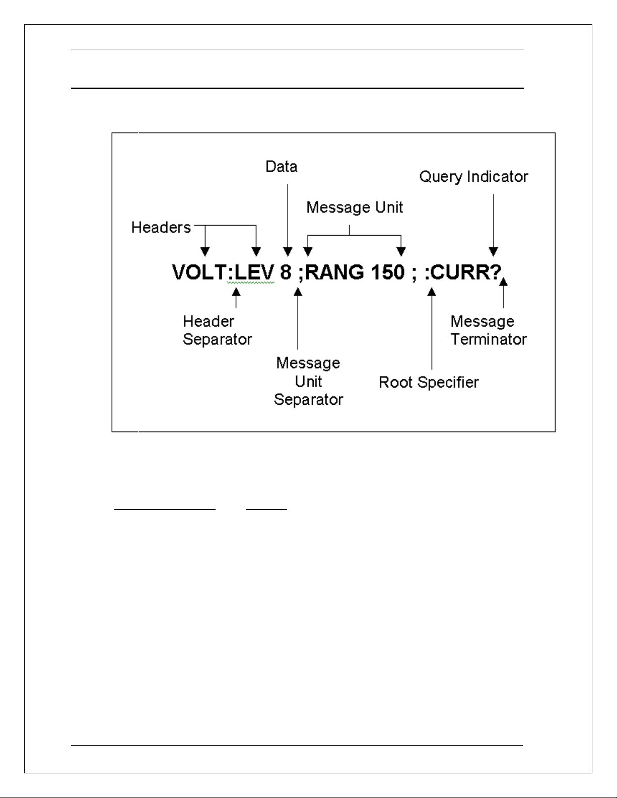
2.4.2 Combining Message Units
The following command message is briefly described here, with details in subsequent
paragraphs.
Figure 2-2: Command Message Structure
The basic parts of the above message are:
Message Component
Example
Headers VOLT LEV RANG CURR
Header Separator The colon in VOLT:LEV
Data 8 150
Data Separator The space in VOLT 8 and RANG 150
Message Units VOLT:LEV 8 RANG 150 CURR?
Message Unit
The semicolons in VOLT:LEV 8; and RANG 150;
Separator
Root Specifier The colon in RANG 150;:CURR?
Query Indicator The question mark in CURR?
Message Terminator The <NL> (newline) indicator. Terminators are not part of
the SCPI syntax
18 Manual P/N 7003-961 Rev AA
Page 19

BPS / MX / RS Series SCPI Programming Manual AMETEK Programmable Power
2.4.3 Headers
Headers are instructions recognized by the AC/DC source. Headers (which are sometimes
known as "keywords") may be either in the long form or the short form.
Long Form The header is completely spelled out, such as VOLTAGE,
STATUS, and OUTPUT.
Short Form The header has only the first three or four letters, such as
VOLT, STAT, and OUTP.
The SCPI interface is not sensitive to case. It will recognize any case mixture, such as
TRIGGER, Trigger, TRIGger. Short form headers result in faster program execution.
Header Convention
In the command descriptions in Chapter 3.4 of this manual, headers are emphasized with
boldface type. The proper short form is shown in upper-case letters, such as DELay.
Header Separator
If a command has more than one header, you must separate them with a colon
(VOLT:LEVel
OUTPut:RELay ON).
Optional Headers
The use of some headers is optional. Optional headers are shown in brackets, such as
OUTPut[:STATe] ON. As previously explained under "The Effect of Optional Headers", if you
combine two or more message units into a compound message, you may need to enter the
optional header.
2.4.4
2.4.5
Query Indicator
Following a header with a question mark turns it into a query (VOLTage?,
VOLTage:RANGe?). If a query contains a parameter, place the query indicator at the end of
the last header (VOLTage:LEVel? MAX).
Message Unit Separator
When two or more message units are combined into a compound message, separate the
units with a semicolon (STATus:OPERation?;QUEStionable?).
Manual P/N 7003-961 Rev. AA 19
Page 20

AMETEK Programmable Power BPS / MX / RS Series SCPI Programming Manual
2.4.6 Root Specifier
When it precedes the first header of a message unit, the colon becomes the root specifier. It
tells the command parser that this is the root or the top node of the command tree. Note the
difference between root specifiers and header separators in the following examples:
2.4.7
CURRent:PROTection:DELay .1
:CURRent:PROTection:DELay .1
CURRent:PROTection:DELay .1;:VOLTage 12.5
You do not have to precede root-level commands with a colon; there is an implied colon in
front of every root-level command.
All colons are header
separators
Only the first colon is a root
specifier
Only the third colon is a root
specifier
Message Terminator
A terminator informs SCPI that it has reached the end of a message. Three permitted
message terminators are:
• newline (<NL>), which is ASCII decimal 10 or hex 0A.
• end or identify (<END>)
• both of the above (<NL><END>).
In the examples of this manual, there is an assumed message terminator at the end of each
message. If the terminator needs to be shown, it is indicated as <NL> regardless of the
actual terminator character.
20 Manual P/N 7003-961 Rev AA
Page 21

BPS / MX / RS Series SCPI Programming Manual AMETEK Programmable Power
2.5 SCPI Data Formats
All data programmed to or returned from the AC source is in ASCII. The data type may be
numerical or character string.
2.5.1
Numerical Data Formats
Symbol Data Form
Talking Formats
<NR1> Digits with an implied decimal point assumed at the right of the
least-significant digit.
Example: 273
<NR2> Digits with an explicit decimal point. Example:.0273
<NR3> Digits with an explicit decimal point and an exponent.
Example: 2.73E+2
<Bool> Boolean Data.
Example: 0 | 1 or ON | OFF
Listening Formats
<Nrf> Extended format that includes <NR1>, <NR2> and <NR3>.
Examples: 273 273.0 2.73E2
<Nrf+> Expanded decimal format that includes <Nrf> and MIN, MAX.
Examples: 273, 273.0, 2.73E2, MAX.
MIN and MAX are the minimum and maximum limit values that
are implicit in the range specification for the parameter.
<Bool> Boolean Data
Example: 0 | 1
2.5.2
Character Data
Character strings returned by query statements may take either of the following forms,
depending on the length of the returned string:
<CRD> Character Response Data. Permits the return of character strings.
<AARD> Arbitrary ASCII Response Data. Permits the return of undelimited 7-bit
ASCII. This data type has an implied message terminator.
<SRD> String Response Data. Returns string parameters enclosed in double
quotes.
Manual P/N 7003-961 Rev. AA 21
Page 22

AMETEK Programmable Power BPS / MX / RS Series SCPI Programming Manual
3. System Considerations and Interface Setup
This chapter addresses some system issues concerning programming. These are AC/DC
Source addressing and the use of the following IEEE-488 system interface controllers:
• National Instruments PCI-GPIB controller with the Windows
• Agilent 82350 PCI GPIB Controller using the SICL driver library.
3.1 Assigning the IEEE-488 Address
The AC/DC source address can be set remotely or localy. All MX/RS/BPS Series AC/DC
source are shipped with the IEEE-488 address set to 1 from the factory. Once the address is
set, you can assign it inside programs. Note that some PC IEEE-488 controller interface
cards may require you to run a setup utility to assign the AC/DC source address. In most
cases however, the instrument address can be set from the application program.
®
gpib-32.dll driver.
For systems using the National Instruments driver, the address of the IEEE-488 controller is
specified in the software configuration program located in the Windows 95
This is not the instrument address. The controller often uses 0 as its own address so the use
of 0 as an instrument address should be avoided. The AC/DC source address can be
assigned dynamically in the application program. (see the National Instruments GP-IB
documentation supplied with the controller card).
3.2 GPIB Controllers
The HP 82350 and National Instruments PCI-GPIB are two popular GPIB controllers for the
PC platform. Each is briefly described here. See the software documentation supplied with
the controller card for more details.
3.2.1
3.2.2
Agilent 82350 Driver
The Afilent 82350 supports either the VISA or SICL instrument driver I/O library which
provides software compatabilty accross all Agilent GPIB controllers. We recommend you
use this driver to develop your code.
National Instruments GP-IB Driver
Your program must include the National Instruments header file for C programs or the
VBIB.BAS and VBIB-32.BAS modules for Visual Basic. If you are using LabView™ or
LabWindows™, make sure to select the correct controller when installing the IDE program.
Prior to running any applications programs, you must set up the GPIB controller hardware
with the configuration program located in the Windows Control Panel. For plug and play
versions of the AT/GPIB-TNT, the setup will be performed when the card is first detected.
®
control panel.
Regardless of the GPIB interface controller used, the power supply expects a message
termination on EOI or line feed, so set EOI w/last byte of Write. It is also recommended that
you set Disable Auto Serial Polling.
All function calls return the status word IBSTA%, which contains a bit (ERR) that is set if the
call results in an error. When ERR is set, an appropriate code is placed in variable IBERR%.
Be sure to check IBSTA% after every function call. If it is not equal to zero, branch to an
error handler that reads IBERR% to extract the specific error.
Error Handling
22 Manual P/N 7003-961 Rev AA
Page 23

BPS / MX / RS Series SCPI Programming Manual AMETEK Programmable Power
If there is no error-handling code in your program, undetected errors can cause
unpredictable results. This includes "hanging up" the controller and forcing you to reset the
system. Both of the above libraries have routines for detecting program execution errors.
Important: Use error detection throughout your application program.
Manual P/N 7003-961 Rev. AA 23
Page 24

AMETEK Programmable Power BPS / MX / RS Series SCPI Programming Manual
3.3 RS232C Interface
MX/RS/BPS power sources that have an RS232 interface but no USB interface use a
special cable to connect to a 9 pin PC serial port. The cable is marked “SOURCE” on one
end and “PC” on the other end and the orientation of the cable is important. The required
serial cable is supplied with the source. If you are unable to locate this cable, you need to
use a cable that conforms to the wiring diagram shown in Figure 3-1.
MX/RS/BPS power source that have both RS232 and USB interface use a standard straight
through DB9 to DB9 serial cable. The orientation of the cable is not important. This cable (CI
P/N 250709) is also supplied with the power source.
Note: If a USB cable is plugged into the USB interface connector of the
power source, the RS232 interface will be disabled. Remove any USB
connection to use the RS232 port.
3.3.1 Serial Communication Test Program
The following sample program written in GW-BASIC can be used to check communication to
the MX/RS/BPS Series source over the RS232C serial interface.
'California Instruments MX Series RS232C Communication Demo Program
'(c) 1995-2002 Copyright California Instruments, All Rights Reserved
'This program is for demonstration purposes only and is not to be
'used for any commercial application
'================================================================
'OPEN COM2. Replace with COM1, COM3 or COM4 for Com port used
'The input and output buffers are set to 2K each although
'this is not required for most operations.
OPEN "COM2:9600,n,8,1,BIN,TB2048,RB2048" FOR RANDOM AS #1
CLS
PRINT "**** INTERACTIVE MODE ****"
'Enter and endless loop to accept user entered commands
DO
INPUT "Enter AC Source Command ('quit' to exit)--> ", cmd$
IF cmd$ <> "QUIT" AND cmd$ <> "quit" THEN
PRINT #1, cmd$ + CHR$(10);
IF INSTR(cmd$, "?") THEN
PRINT #1, CHR$(4);
LINE INPUT #1, response$
PRINT response$
END IF
'Check for Errors after each command is issued
PRINT #1, "*ESR?" + CHR$(10);
PRINT #1, CHR$(4);
LINE INPUT #1, esr$
esr% = VAL(esr$) AND 60
IF esr% AND 4 THEN
PRINT "*** Query Error Reported by AC Source ***"
END IF
IF esr% AND 8 THEN
PRINT "*** Instrument Dependent Error Reported by AC Source ***"
END IF
IF esr% AND 16 THEN
PRINT "*** Command Execution Error Reported by AC Source ***"
END IF
IF esr% AND 32 THEN
PRINT "*** Command Syntax Error Reported by AC Source ***"
END IF
END IF
LOOP UNTIL cmd$ = "QUIT" OR cmd$ = "quit"
'Close COM port on exit
CLOSE #1
END
24 Manual P/N 7003-961 Rev AA
Page 25
BPS / MX / RS Series SCPI Programming Manual AMETEK Programmable Power
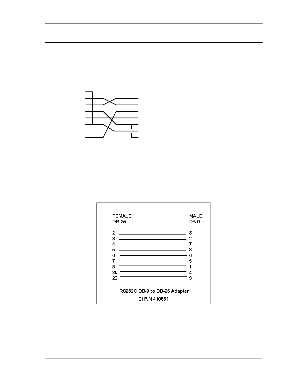
3.3.2 Serial Cable Diagram
For MX/RS/BPS units with an RS232 interface but no USB interface, the following wiring
diagram is required for the serial interface cable between the AC/DC power source and a
PC communications port connector.
DB-9 PC
Pin
1
2
3
4
5
6
7
8
9
DB-9 AC Source
Direction
Pin
output
1
input
2
output
3
output
4
-
5
input
6
-
7
-
8
output
9
Description
reserved
Receive data(RxD)
Tr ansmit da ta (TxD)
Data Terminal Ready (DTR)
Signal Ground
Data Set Re ady (DSR)
no connect
no connect
reserved
Figure 3-1: RS232C Interface cable wiring diagram
If the controller or PC only has a 25 pin D sub COM port, a 25 to 9 pin adaptor is required to
use the serial cable supplied with the MX/RS/BPS. These small triangular shape adaptors
can be purchased at most computer stores or outlets like Radio Shack. If none can be
found, one can be constructed using the diagram shown below.
Figure 3-2: DB25 to DB9 Adaptor pinout
Manual P/N 7003-961 Rev. AA 25
Page 26

AMETEK Programmable Power BPS / MX / RS Series SCPI Programming Manual
3.4 USB Interface
A standard USB Series B device connector is located on the rear panel for remote control. A
standard USB cable between the AC Source and a PC or USB Hub may be used. Refer to
user manual 7003-960 for connector pin out information.
Unlike RS232, there are no generic drivers available as a rule for use in programming
environments such as LabView, LabWindows/CVI or Visual Basic. However, support for
USB is included under VISA and may be used to interface to the power source using the
USB interface.
A virtual serial port utility is provided on CD ROM CIC496, which ships with the power
source. This utility will provide a virtual COM port on a PC under Windows XP. This allows
programs to use the USB port as though it is a regular serial port on the PC. The baud rate
for this mode of operation is fixed at 460,800. The USB-Serial Adaptor installation must be
run to install the virtual com port driver. This option is only supported under Windows XP at
this time.
Note: Use of the USB port to control more than one power source from a single PC
is not recommended, as communication may not be reliable. Use GPIB
interface for multiple power source control.
3.4.1 USB Driver Installation
When connecting the AC source through the USB interface to Windows XP PC, the
presence of a new USB device will be detected. Windows will display a dialog after a short
delay prompting the user to install the USB device drivers. There are two steps to this
process.
The first one installs the USB decive itself. The second step allows installation of the USB to
COM virtual port driver. This driver will allow access to the AC source USB interface using a
virtual COM port. Many programming environments support RS232 access but not USB.
The USB-to-COM virtual port driver is distributed on the CIC496 CD ROM.
Step 1: USB Device Driver installation
26 Manual P/N 7003-961 Rev AA
Page 27
BPS / MX / RS Series SCPI Programming Manual AMETEK Programmable Power
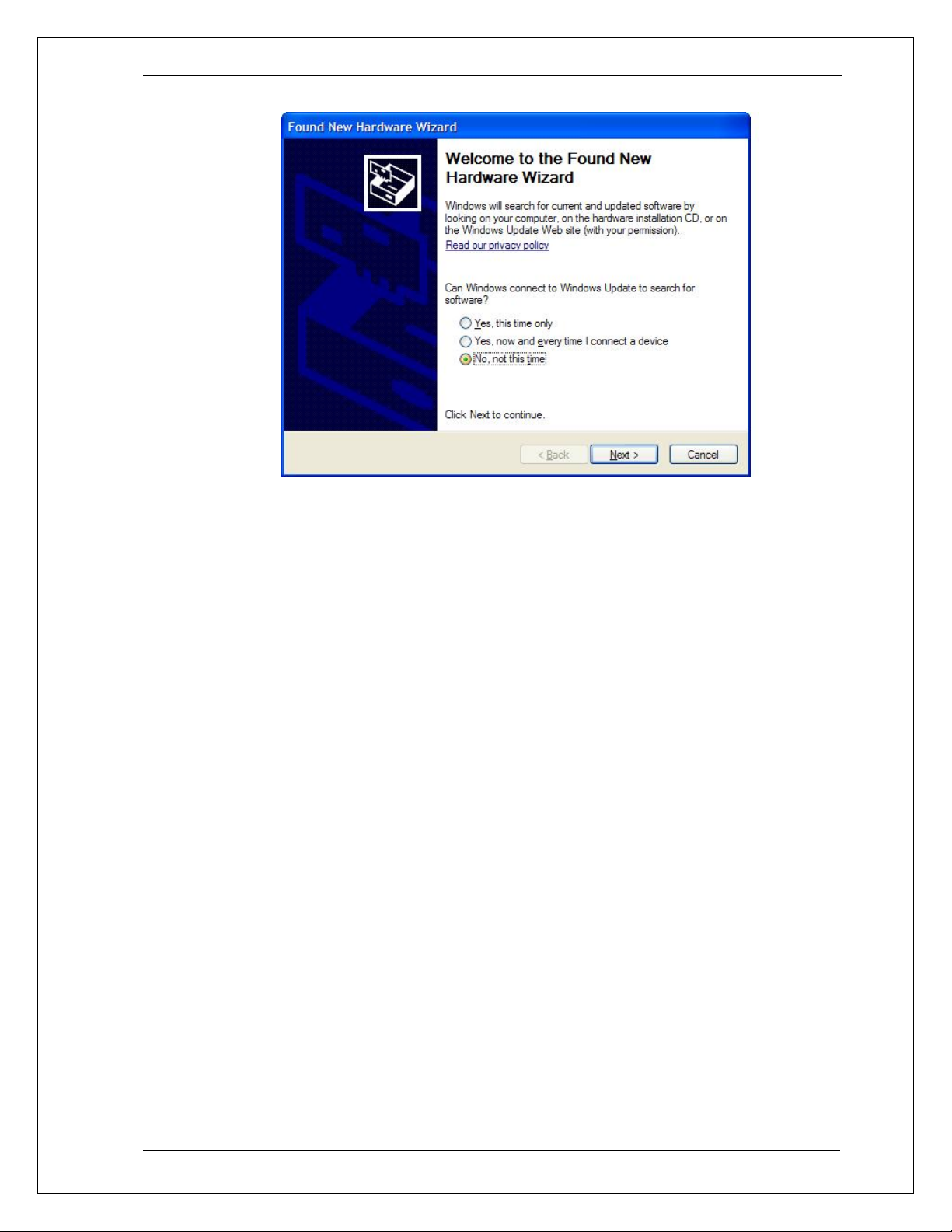
When the “Found New Hardware Wizard” dialog appears, select the “No, not this
time.”option. The drivers are not available on line. Click on Next button to continue.
Manual P/N 7003-961 Rev. AA 27
Page 28
AMETEK Programmable Power BPS / MX / RS Series SCPI Programming Manual
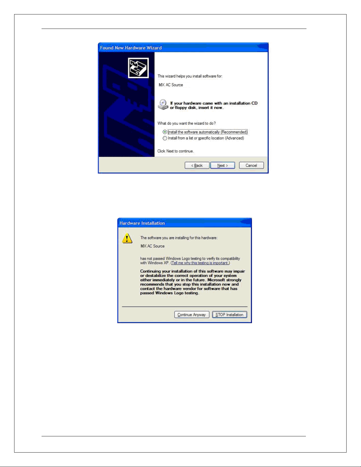
The next dialog will ask you to install the software for the MX/RS/BPS AC Source. Select the
“Install the software automatically (Recommended)” option and click on Next to continue. If
you are prompted for a file path, browse to the CD root drive and then USB_Inf (eg.
D:\USB_Inf).
The USB device drivers have not been Windows XP Logo certified. Due to the limited
distribution of these drivers, this is unlikely to be done. This Logo certification has no
bearing on the functionality or legitimacy of this device driver so you can ignore this
message. Click the “Continue Anyway” button to continue. Note that some PCs may have
this verification disabled in which case this screen will not pop up.
The installation will now proceed. This process may take several minutes to complete.
28 Manual P/N 7003-961 Rev AA
Page 29
BPS / MX / RS Series SCPI Programming Manual AMETEK Programmable Power
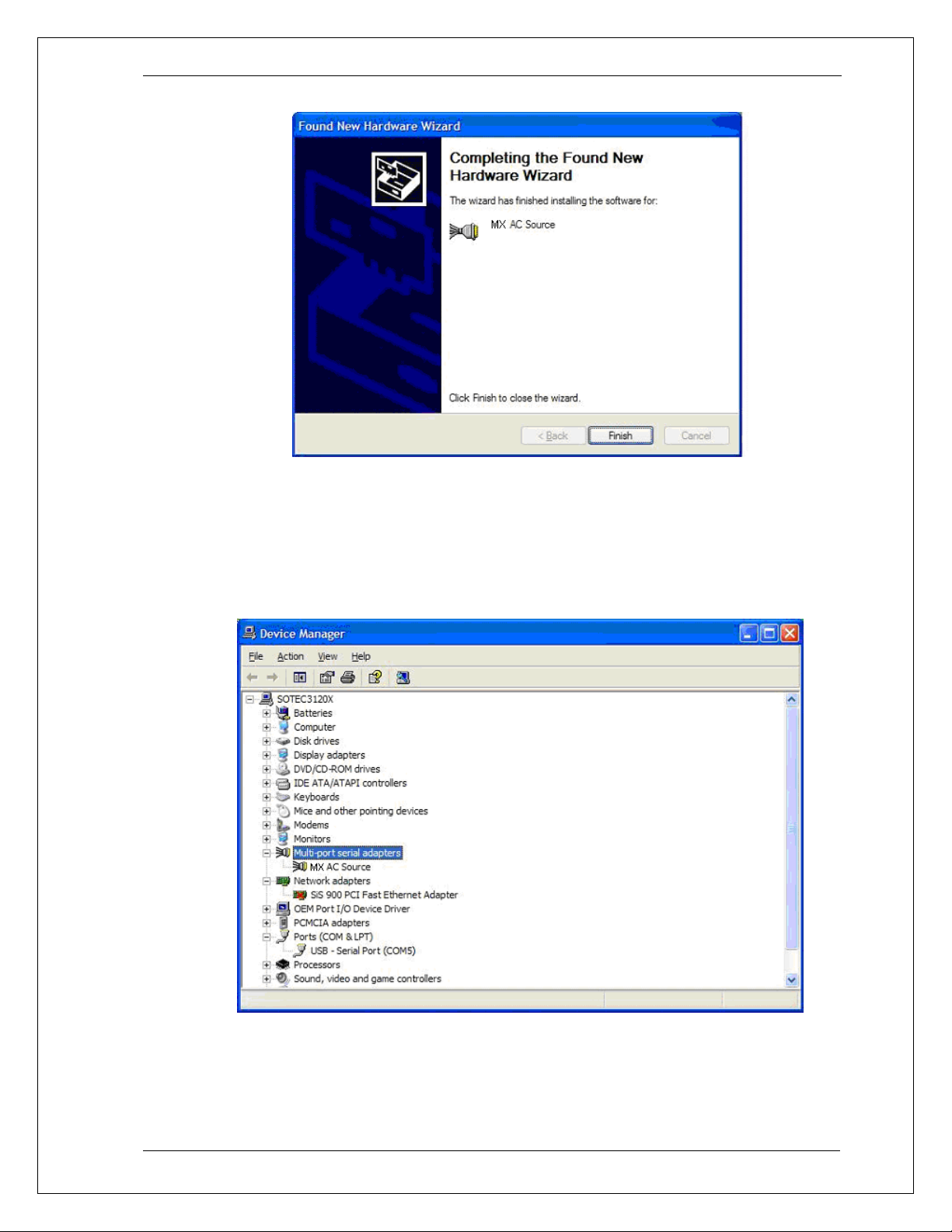
Once completed, the dialog box shown above will appear signaling the device drivers have
been installed. The USB interface is now available to the PC’s operating system. To
complete the install process, click on the “Finish” button.
To verify the USB port is available, you can access the Windows System Properties screen,
select the Hardware tab and open the Windows Device Manager screen. The MX Source
should be listed under “Multi-port serial adapters” as shown in the image below.
Figure 3-3: Windows XP Device Manager - USB Port
Manual P/N 7003-961 Rev. AA 29
Page 30
AMETEK Programmable Power BPS / MX / RS Series SCPI Programming Manual
Step 2: USB to Com Virtual Device Driver installation
The second step allows installation of the USB to COM virtual port driver. This driver will
allow access to the AC source USB interface using a virtual COM port. Many programming
environments support RS232 access but not USB. The use of this driver will allow you to
program the power source through the USB port as though it was an RS232 port. The USBto-COM virtual port driver is distributed on the CIC496 CD ROM. This step is required to use
the included Gui Windows software or other application software through USB.
To continue the installation, make sure the CIC496 CD Rom is available. Insert in the CD
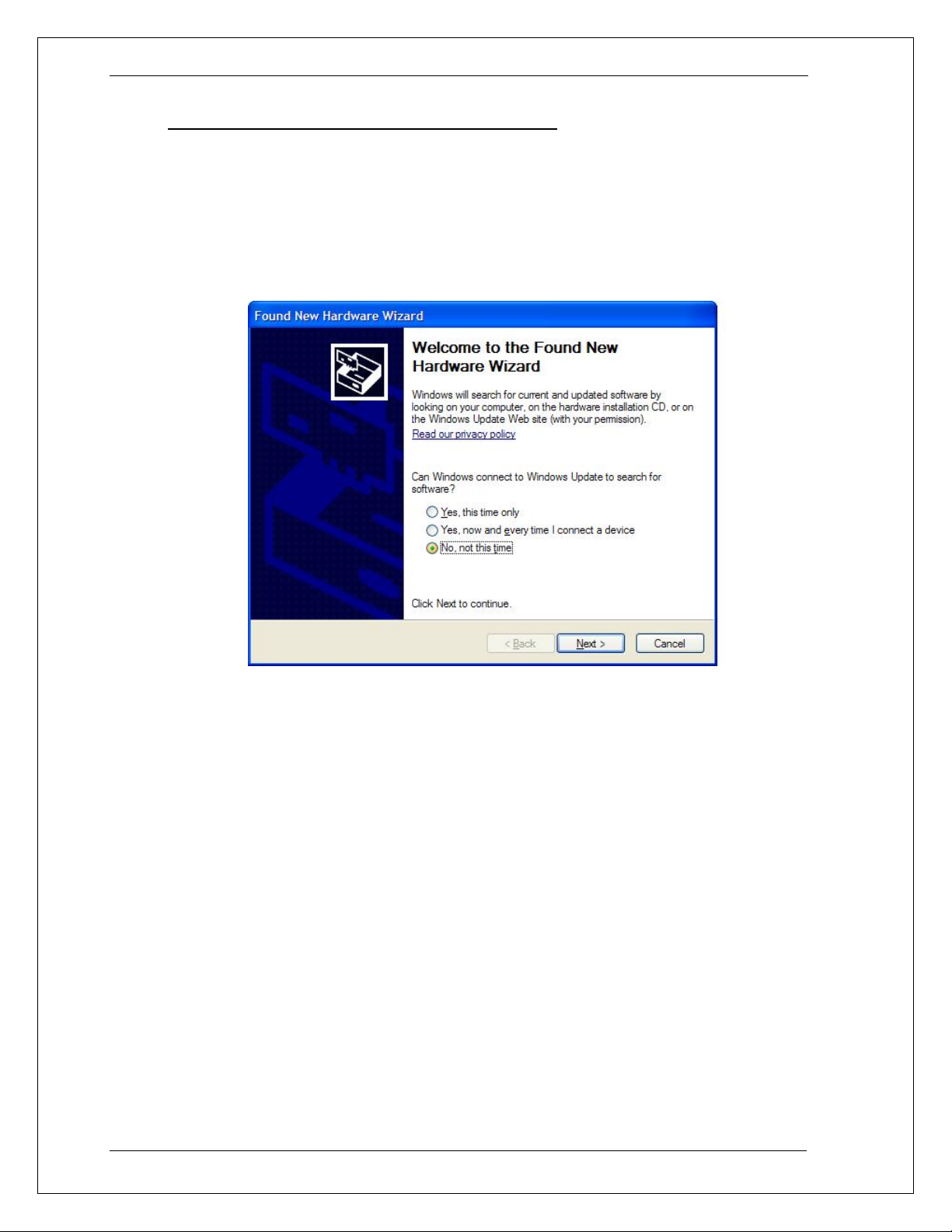
ROM drive if needed. If the auto-run screen appears, you can close it.
When the “Found New Hardware Wizard” dialog appears, select the “No, not this
time.”option. The drivers are not available on line. Click on Next button to continue.
30 Manual P/N 7003-961 Rev AA
Page 31

BPS / MX / RS Series SCPI Programming Manual AMETEK Programmable Power
The next dialog will ask you to install the software for the MX AC Source. Select the “Install
the software automatically (Recommended)” option and click on Next to continue. If you are
prompted for a file path, browse to the CD root drive and then USB_Inf (eg. D:\USB_Inf).
The USB device drivers have not been Windows XP Logo certified. Due to the limited
distribution of these drivers, this is unlikely to be done. This Logo certification has no
bearing on the functionality or legitimacy of this device driver so you can ignore this
message. Click the “Continue Anyway” button to continue. Note that some PCs may have
this verification disabled in which case this screen will not pop up.
The installation will now proceed. This process may take several minutes to complete. Once
completed, the final dialog will appear as shown.
Manual P/N 7003-961 Rev. AA 31
Page 32

AMETEK Programmable Power BPS / MX / RS Series SCPI Programming Manual
32 Manual P/N 7003-961 Rev AA
Page 33

BPS / MX / RS Series SCPI Programming Manual AMETEK Programmable Power
The USB to Com virtual port is now available to the PC’s operating system. To complete the
install process, click on the “Finish” button. To verify the virtual com port is available, you
can access the Windows System Properties screen, select the Hardware tab and open the
Windows Device Manager screen. The USB redirector should be listed under “Ports (COM
& LPT)” as shown in the image below. The com port number is automatically assigned.
Note the com port number for subsequent reference in your application software or when
selected the COM port in the Gui Interface screen. This port number may be changed by
opening the USB redirector properties and clicking on Port Settings, then Advanced, and
selecting which port to use from the COM Port number drop down box.
Figure 3-4: Windows XP Device Manager – Virtual Com Port
Once completed, you can remove the CIC496 CD Rom. The USB interface to the AC source
is now available for use.
Manual P/N 7003-961 Rev. AA 33
Page 34

AMETEK Programmable Power BPS / MX / RS Series SCPI Programming Manual
3.4.2 USB Interface Use
Note that the power source will be detected automatically when turn on or plugged in once
the drivers have been installed. It is recommended however to close any open USB
connections to the AC source before turning it off.
To use the USB interface, you may use the Gui Windows software supplied with the power
source or develop your own application code. In either case, set the baud rate on the power
source to 460,800 in the Configuration menu. From the Front panel, press MENU key, scroll
to CONFIGURATION and press ENTER key. Select BAUDRATE field and scroll to 460800.
For use with the Gui program, select the “USB / RS232C Serial” interface type and set the
Baud rate to 460800.
Figure 3-5: Gui Interface Settings for use of USB port.
Note: Use of the USB port to control more than one power source from a single PC
is not recommended, as communication may not be reliable. Use GPIB
interface for multiple power source control.
34 Manual P/N 7003-961 Rev AA
Page 35

BPS / MX / RS Series SCPI Programming Manual AMETEK Programmable Power
3.5 LAN Interface Option
An Ethernet LAN interface option is available as an option for the MX/RS/BPS Series power
sources. This option must be specified at the time of order. A –LAN option indicator will
appear on the model number tag at the rear-panel of the power source to indicate the
presence of this option. Also, a RJ45 socket will be present on the rear panel.
Using LAN lets you communicate with the instrument remotely, it is fast, simple and the LAN
from your PC does not require any additional proprietary software or cards.
Note: If a USB cable is plugged into the USB interface connector of the
power source, the LAN interface will be disabled. Remove any USB
connection to use the LAN / Ethernet port.
An RJ45 Ethernet 10BaseT connector is located on the rear panel if the –LAN option is
installed. A standard RJ45 UTP patch cord between the AC Source and a network Hub may
be used to connect the AC source to a LAN. For direct connection to a PC LAN card, a
crossover RJ45 cable is required. Consult your network administrator for directions on
connecting the AC source to any corporate LAN.
If the –LAN Ethernet interface option is present, the MAC Address (Media Access Control) of
the Ethernet port is printed on the serial tag of the power source. The serial tag is located on
the rear panel of the unit.
3.5.1
3.5.2
MAC Address
Each power source with the –LAN option installed has a unique network address (MAC
address). The MAC address (Media Access Conrol) is a unique hexadecimal address and
is listed on a label on the rear panel of the power source. To operate the power source on a
network, this MAC address needs to be assigned to a TCP/IP address, which will be used to
address the device on the network.
Setting the TCP/IP Address
The first decision you need to make is how to connect the instrument. You can connect the
instrument directly to a network LAN port with a LAN cable, or you can connect it directly to
the PC. When connecting the instrument directly to the PC LAN port you will need a special
cable called a cross connect cable. Once connected you must establish an IP address for
the instrument. An IP address consists of four groups of numbers separated by a decimal.
Dynamic Host Configuration Protocol (DHCP) is typically the easiest way to configure the
instrument for LAN communication. DHCP automatically assigns a dynamic IP address to a
device on a network. You will need to enter the IP address on the Interface screen of the
GUI to control the power source.
The GUI has a built in utility that let’s you determine the IP address assigned by the network
DHCP server. It may also be used to set a static IP address. To use the LAN option, MXGui
version 2.1.0.0 or higher is required. The latest MXGui version can be downloaded from the
California Instrument web site. (www.programmablepower.com)
Manual P/N 7003-961 Rev. AA 35
Page 36

AMETEK Programmable Power BPS / MX / RS Series SCPI Programming Manual
Use the “Locate IP” button on the interface configuration screen to bring up the IP configuration
utility screen. To determine what IP address was assigned, select the “Get IP Address from MAC
Address in the Configuration selection. The MAC address should be listed on the serial tag on the
back of the unit. Enter the MAC address and click on “Get IP Address”.
This process may take several minutes to complete so be patient. If the IP address is found, it will
be displayed below the MAC address. If it can’t be found, all zero’s will be displayed instead.
Close the program to return to the GUI interface configuration screen. Then use the “Update IP”
button to tranfer the new IP address into the GUI IP Address box. You can also enter the IP address
manually.
The same IP Configuration utility can be used to set the power source LAN option to either static IP
or DHCP IP mode. See the on line help for futher instructions.
36 Manual P/N 7003-961 Rev AA
Page 37

BPS / MX / RS Series SCPI Programming Manual AMETEK Programmable Power
3.5.3 Socket Port Number
Now that a connection has been verified, you can develop your application code. If you are
using one of the Microsoft environments, the Winsock protocol which is part of the Windows
operating system can be used. Similar capabilities are supported on other operating
systems.
To use Winsock, your will have to specificy the port number of the power source’s LAN
interface. The port number determines the protocol for the communication. The power
source uses ASCII characters and instrument SCPI commands for remote control. The
IANA registered Port number for the Instrument SCPI interface is 5025.
TCP Remote port = 5025
The port numbe is factory set to 5025.
3.5.4
IP Ping
You can also test the IP address from your Windows PC. An easy way to do so is to use the
ping utility under MS DOS. To do so, bring up a DOS window using the start menu:
Start>Programs>Accessories>Command Prompt)
At the command prompt type
ping <IP address>.
This will send an IP ping request to the power source. For this to work, the power source
must be turned on and connected to the same network as the PC. Also, the power source
interface configuration must be set to use a baud rate of 460,800. If everything is working it
will look like this:
Figure 3-6: Pinging AC Source LAN IP address.
Manual P/N 7003-961 Rev. AA 37
Page 38

AMETEK Programmable Power BPS / MX / RS Series SCPI Programming Manual
4. SCPI Command Reference
4.1 Introduction
Related Commands
Where appropriate, related commands or queries are included. These are listed because
they are either directly related by function, or because reading about them will clarify or
enhance your understanding of the original command or query.
Subsystem commands
Subsystem commands are specific to AC/DC source functions. They can be a single
command or a group of commands. The groups are comprised of commands that extend
one or more levels below the root. The description of common commands follows the
description of the subsystem commands.
The subsystem command groups are listed in alphabetical order and the commands within
each subsystem are grouped alphabetically under the subsystem. Commands followed by a
question mark (?) take only the query form. When commands take both the command and
query form, this is noted in the syntax descriptions.
IEEE 488.2 common commands
Common commands are defined by the IEEE-488.2 standard and are described in chapter 0
of this manual.
38 Manual P/N 7003-961 Rev AA
Page 39

BPS / MX / RS Series SCPI Programming Manual AMETEK Programmable Power
4.2 Calibration Subsystem
The commands in this subsystem allow you to do the following:
• Enable and disable the calibration mode
• Calibrate the measured current and measured voltage and store new calibration in
nonvolatile memory.
• Calibrate the current and voltage output levels, and store new calibration constants in
nonvolatile memory.
• Calibrate the output impedance of the AC source, and store new calibration constants in
nonvolatile memory.
Note: MX Series II models have fewer calibration points than series I models. The
Series II will accept all Series I calibration commands but some will have no
effect on Series II models. See the MX user manual 7003-960 or MX15 user
manual 7005-960 or RS user manual M440036 for specific calibration settings.
Also, the elevated temperature calibration setpoints are not required on Series
II MX/RS/BPS systems.
The commands in this subsystem allow you to do the following:
Subsystem Syntax
CALibrate
:PASSword Allows entry of calibration password required to
change calibration coefficients
:SAVE Saves new or modified calibration coefficients
:MEASure
:CURRent
[:AMBient] Ambient temperature calibrations
[:AC]
[:FSCale] Calibrate full-scale AC current measurements
:DC
[:FSCale] Calibrate full-scale DC current measurements
:ZERO Cancel DC current measurements offset
:TEMPerature Elevated temperature calibrations
[:AC]
[:FSCale] Calibrate full-scale AC current measurements at
higher temperature
:DC
[:FSCale] Calibrate full-scale AC current measurements at
higher temperature
:ZERO Cancel AC current measurements offset at a higher
temperature
:VOLTage
[:AMBient] Ambient temperature calibrations
[:AC]
[:FSCale] Calibrate full-scale AC voltage measurements
:DC
[:FSCale] Calibrate full-scale AC voltage measurements
:ZERO Cancel AC voltage measurements offset
:TEMPerature Elevated temperature calibrations
[:AC]
Manual P/N 7003-961 Rev. AA 39
Page 40

AMETEK Programmable Power BPS / MX / RS Series SCPI Programming Manual
[:FSCale] Calibrate full-scale AC voltage measurements at
higher temperature
:DC
[:FSCale] Calibrate full-scale AC voltage measurements
:ZERO Cancel AC voltage measurements offset
[:SOURce]
:PHASe Calibrate output phase angle relative to external sync.
:VOLTage
[:AC]
:LRANge
[:FSCale] Calibrate full-scale output voltage at low voltage
range
:ZERO Trim output voltage offset at low voltage range.
:HFRequency Calibrate full scale output voltage at low voltage
range and high frequency.
:HRANge
[:FSCale] Calibrate full-scale output voltage at high voltage
range
:ZERO Trim output voltage offset at high voltage range.
:HFRequency Calibrate full scale output voltage at high voltage
range and high frequency.
:DC
:LRANge
[:FSCale] Calibrate full-scale output dc voltage at low voltage
range.
:ZERO Trim output dc voltage offset at low voltage range.
:HRANge
[:FSCale] Calibrate full-scale output dc voltage at high voltage
range. (positive DC)
:ZERO Trim output dc voltage offset at high voltage range.
:IMPedance
:REAL
[:FSCale] Calibrate the real part of the programmable output
impedance at full-scale value
:ZERO Calibrate the real part of the programmable output
impedance at minimum value
:REACtive
[:FSCale] Calibrate the reactive part of the programmable
output impedance at full-scale value
:ZERO Calibrate the reactive part of the programmable
output impedance at minimum value
:IHARmonic? IEC413 interharmonic
40 Manual P/N 7003-961 Rev AA
Page 41

BPS / MX / RS Series SCPI Programming Manual AMETEK Programmable Power
4.2.1 Password
CALibrate:PASSword
This command allows the entry of the calibration password. The calibration password is
required to use the data entry form of the calibration commands. Without the use of this
password, only the query form can be used to query any calibration coefficient but no new
calibration can be performed. Calibration queries always return two values. The first value is
the calibration coefficient itself, the second value is the temperature associated with that
coefficient. All temperate coefficients except for full-scale AC voltage are computed by the
AC/DC power source controller.
The calibration password is defined as the numeric portion of the AC/DC power source
serial number spelled backwards. The password needs to be enclosed by single or double
quotation marks. Thus, if the units serial number is HK12345, the calibration password is
“54321” and the command syntax would be:
CAL:PASS “54321”
Note that any non-numeric characters such as the HK in the example shown here need to
be discarded when sending the calibration password. Only the numeric portion is to be used.
Command Syntax CALibrate:PASSword<SRD>
Parameters <numeric portion of serial number reversed> (default)
Examples CAL:PASS '34593' CAL:PASS "35461"
Related Commands *IDN?
4.2.2 Save
CALibrate:SAVE
This command saves all calibration coefficients to non-volatile memory. This command
should be issued after all calibration adjustements have been made. If not, all changes will
be lost when unit is turned off and the previous calibration values will take effect the next
time the unit is powered up.
Note: Saving calibration data to non-volatile memory requires more time to process
Command Syntax CALibrate:SAVE<SRD>
Parameters None
Examples CAL:SAVE
Related Commands CAL:PASS
by the MX/RS/BPS controller than other commands. As such, it is
recommended to hold off on sending additional commands for about 300
msecs
Manual P/N 7003-961 Rev. AA 41
Page 42

AMETEK Programmable Power BPS / MX / RS Series SCPI Programming Manual
4.2.3 Current Measurement
CALibrate:MEASure:CURRent[:AMBient][:AC][:FSCale] <NRf>
This command initiates the calibration of the AC current measurement at full scale and at
ambient temperature.
Command Syntax CALibrate:MEASure:CURRent[:AMBient][:AC][:FSCale]
Parameters <NRf> (actual load current measured with external device)
Examples CAL:MEAS:CURR 11.5
Query Syntax CALibrate:MEASure:CURRent?
Returned Parameters <NR2> (value range -1000 to +1000)
Related Commands CALibrate:MEASure:CURRent:TEMPerature[:AC][:FSCale]
CALibrate:MEASure:CURRent[:AMBient]:DC[:FSCale] <NRf>
This command initiates the calibration of the DC current measurement at full scale and at
ambient temperature.
Command Syntax CALibrate:MEASure:CURRent[:AMBient]:DC[:FSCale]
Parameters <NRf> (actual load current measured with external device)
Examples CAL:MEAS:CURR:DC 11.5
Query Syntax CALibrate:MEASure:CURRent:DC?
Returned Parameters <NR2> (value range -1000 to +1000)
Related Commands CALibrate:MEASure:CURRent:TEMPerature:DC[:FSCale]
CALibrate:MEASure:CURRent[:AMBient]:DC:ZERO <NRf>
This command initiates the offset adjustment of the DC current measurement at ambient
temperature.
Command Syntax CALibrate:MEASure:CURRent[;AMBient]:DC:ZERO
Parameters <NRf> (0 or desired offset value)
Examples CAL:MEAS:CURR:DC:ZERO
Query Syntax CALibrate:MEASure:CURRent:DC:ZERO?
Returned Parameters <NR1> (value range -127 to +128)
Related Commands CALibrate:MEASure:CURRent:TEMPerature:DC:ZERO
CALibrate:MEASure:CURRent:TEMPerature[:AC][:FSCale] <NRf>
This command initiates the calibration of the AC current measurement at full scale and at
elevated temperature.
Command Syntax CALibrate:MEASure:CURRent:TEMPerature[:AC][:FSCale]
Parameters <NRf> (actual load current measured with external device)
Examples CAL:MEAS:CURR:TEMP 11.5
Query Syntax CALibrate:MEASure:CURRent:TEMP?
Returned Parameters <NR1> (value range -1000 to +1000)
Related Commands CALibrate:MEASure:CURRent[:AMB][:AC][:FSCale]
42 Manual P/N 7003-961 Rev AA
Page 43

BPS / MX / RS Series SCPI Programming Manual AMETEK Programmable Power
CALibrate:MEASure:CURRent:TEMPerature:DC[:FSCale] <NRf>
This command initiates the calibration of the DC current measurement at elevated
temperature.
Command Syntax CALibrate:MEASure:CURRent:TEMPerature:DC[:FSCale]
Parameters <NRf> (0 or desired offset value)
Examples CAL:MEAS:CURR:TEMP:DC
Query Syntax CALibrate:MEASure:CURRent:TEMPerature:DC?
Returned Parameters <NR1> (value range -1000 to + 1000
Related Commands CALibrate:MEASure:CURRent[:AMB]:DC[:FSCale]
CALibrate:MEASure:CURRent:TEMPerature:DC:ZERO <NRf>
This command initiates the offset adjustment of the DC current measurement at elevated
temperature.
Command Syntax CALibrate:MEASure:CURRent:TEMPerature:DC:ZERO
Parameters <NRf> (0 or desired offset value)
Examples CAL:MEAS:CURR:TEMP:DC:ZERO
Query Syntax CALibrate:MEASure:CURRent:TEMPerature:DC:ZERO?
Returned Parameters <NR1> (value range 0 to +5)
Related Commands CALibrate:MEASure:CURRent[:AMB]:DC:ZERO
Manual P/N 7003-961 Rev. AA 43
Page 44

AMETEK Programmable Power BPS / MX / RS Series SCPI Programming Manual
4.2.4 Voltage Measurement
CALibrate:MEASure:VOLTage[:AMBient][:AC][:FSCale] <NRf>
This command initiates the calibration of the rms voltage measurement at full scale and at
ambient temperature.
Command Syntax CALibrate:MEASure:VOLTage[:AMBient][:AC][:FSCale]
Parameters <NRf> (actual rms output voltage measured with external device)
Examples CAL:MEAS:VOLT 120
Query Syntax CALibrate:MEASure:VOLTage?
Returned Parameters <NR2> (value range -1000 to +1000)
Related Commands CALibrate:MEASure:VOLTage:TEMPerature:[:AC][:FSCale]
CALibrate:MEASure:VOLTage[:AMBient]:DC[:FSCale] <NRf>
This command initiates the calibration of the DC voltage measurement at full scale and at
ambient temperature.
Command Syntax CALibrate:MEASure:VOLTage[:AMBient]:DC[:FSCale]
Parameters <NRf> (actual DC output voltage measured with external device)
Examples CAL:MEAS:VOLT:DC 120
Query Syntax CALibrate:MEASure:VOLTage:DC?
Returned Parameters <NR2> (value range -1000 to +1000)
Related Commands CALibrate:MEASure:VOLTage:TEMPerature:DC[:FSCale]
CALibrate:MEASure:VOLTage[:AMBient]:DC:ZERO <NRf>
This command initiates the offset adjustment of the DC voltage measurement at ambient
temperature.
Command Syntax CALibrate:MEASure:VOLTage[:AMBient]:DC:ZERO
Parameters <NRf> (0 or desired offset value)
Examples CAL:MEAS:VOLT:DC:ZERO 0
Query Syntax CALibrate:MEASure:VOLT:DC:ZERO?
Returned Parameters <NR1> (value range -127 to +128)
Related Commands CALibrate:MEASure:VOLTage:TEMPerature:DC:ZERO
CALibrate:MEASure:VOLTage:TEMPerature[:AC][:FSCale] <NRf>
This command initiates the calibration of the rms voltage measurement at full scale and at
elevated temperature.
Command Syntax CALibrate:MEASure:VOLTage:TEMPerature[:AC][:FSCale]
Parameters <NRf> (actual rms output voltage measured with external device)
Examples CAL:MEAS:VOLT:TEMP 120
Query Syntax CALibrate:MEASure:VOLTage:TEMPerature?
Returned Parameters <NR2> (value range -1000 to +1000)
Related Commands CALibrate:MEASure:VOLTage[:AMBient][:AC][:FSCale]
44 Manual P/N 7003-961 Rev AA
Page 45

BPS / MX / RS Series SCPI Programming Manual AMETEK Programmable Power
CALibrate:MEASure:VOLTage:TEMPerature:DC[:FSCale] <NRf>
This command initiates the calibration of the DC voltage measurement at full scale and at
elevated temperature.
Command Syntax CALibrate:MEASure:VOLTage:TEMPerature:DC[:FSCale]
Parameters <NRf> (actual DC output voltage measured with external device)
Examples CAL:MEAS:VOLT:TEMP 120
Query Syntax CALibrate:MEASure:VOLTage:TEMPerature:DC?
Returned Parameters <NR2> (value range -1000 to +1000)
Related Commands CALibrate:MEASure:VOLTage[:AMBient]:DC[:FSCale]
CALibrate:MEASure:VOLTage:TEMPerature:DC:ZERO <NRf>
This command initiates the offset adjustment of the rms voltage measurement at elevated
temperature.
Command Syntax CALibrate:MEASure:VOLTage:TEMPerature:DC:ZERO
Parameters <NRf> (0 or desired offset value)
Examples CAL:MEAS:VOLT:TEMP:DC:ZERO 0
Query Syntax CALibrate:MEASure:VOLT:DC:ZERO?
Returned Parameters <NR2> (value range -20 to +20)
Related Commands CALibrate:MEASure:VOLTage[:AMBient]:DC:ZERO
Manual P/N 7003-961 Rev. AA 45
Page 46

AMETEK Programmable Power BPS / MX / RS Series SCPI Programming Manual
4.2.5 Output Phase
CALibrate:PHASe <NRf+>
The MX/RS Series AC/DC power source controller can be operated using its internal
timebase reference, an external clock or in external sync mode. (See FREQ:MODE
command on page 81. When using in external clock or sync mode, it may be desirable to
shift the phase output with respect to the external reference. The feature may be used to
create a deliberate phase offset or to compensate for phase delays that may occur in the
external sync signal path. The phase calibration command can be used to program a
negative or positive phase offset for phase in degrees with respect to the external sync. Note
that this calibration adjustment only applies to the external clock or sync for phase A. Phase
B and C are always programmed with respect to phase A and their calibration offset is with
respect to phase A. The phase to be calibrated can be selected using the INST:NSEL
command.
The phase offset is expressed in degrees and can range from -360.0 to +360.0 degrees.
The resolution of the phase angle adjustment (0.1°) is the same as the one for programming
phase angles (See [SOURce:]PHASe command).
Command Syntax CALibrate:PHASe <NRf+>
Parameters <NRf> (a value between -360.0 and +360.0)
Examples CAL:PHAS -2.3
Query Syntax CAL:PHAS?
Returned Parameters <NR1> (value range -180.0 to +180.0)
Related Commands FREQ:MODE [SOURce:]PHASe INST:NSEL
4.2.6 Output Calibration Command Sequence
Note that the ALC mode normally interferes with the full scale output voltage calibration. As such, to
perform full scale output voltage calibration over the bus, the ALC mode must be off. This is done
automatically by sending the CAL:PASS command. However, to use the ALC mode to obtain the
correct output voltage, it must be on while the outputs are set. The specific sequence that has to be
followed is shown below:
CAL:PASS "nnnnn" /* Turns the calibration mode on.
INST:COUP ALL /* Couples all phases in three mode. (Not needed in 1
phase mode)
VOLT nnn /* Set desired calibration voltage level. See user manual.
FREQ nn /* Set desired calibration frequency. See user manual.
ALC ON /* Enable ALC to adjust output based on measurement
data. Note that the voltage measurement calibration must
be done first.
CAL:PASS "nnnnn" /* Cal mode has been disabled by ALC ON command so it
must be turned on again.
INST:NSEL 1 /* Select phase A. (Not needed for single phase mode).
CAL:VOLT:AC:LRAN nnn
CAL:VOLT:AC:LRAN? /* Optional. Returns coefficient between 0.9 and 1.1
/* Repeat last three commands for phase B and C using
INST:NSEL 2 and INST:NSEL 3 respectively.
CAL:SAVE /* Saves coeffient
This procedure applies to both AC and DC modes and high and low voltage ranges.
46 Manual P/N 7003-961 Rev AA
Page 47

BPS / MX / RS Series SCPI Programming Manual AMETEK Programmable Power
4.2.7 Output - AC Voltage
CALibrate[:SOURce]:VOLTage[:AC]:LRANge[:FSCale] <NRf+>
This command will result in the calibration coefficent being calculated for the AC full scale
output voltage at the low voltage range.
Command Syntax CALibrate:VOLTage:LRANge <NRf+>
Parameters <NRf> (programmed output voltage)
Examples CAL:VOLT:LRAN 120
Query Syntax CALibrate:VOLTage:LRANge?
Returned Parameters <NRf> (cal coefficient value range 0.9 to 1.1)
Related Commands CAL:VOLT:LRAN:ZERO CAL:VOLT:LRAN:HFR
CALibrate[:SOURce]:VOLTage[:AC]:LRANge:ZERO <NRf+>
This command will set the calibration coefficent for the output voltage offset at the low
voltage range.
Command Syntax CALibrate:VOLTage:LRANge:ZERO <NRf+>
Parameters <NRf> (a value between -127 and +128)
Examples CAL:VOLT:LRAN:ZERO +10
Query Syntax CALibrate:VOLTage:LRANge:ZERO?
Returned Parameters <NR1> (value range -127 to +128)
Related Commands CAL:VOLT:LRAN CAL:VOLT:LRAN:HFR
CALibrate[:SOURce]:VOLTage[:AC]:LRANge:HFRequency <NRf+>
This command will set the calibration coefficent for the AC full scale output voltage at the low
voltage range and at high output frequency
Command Syntax CALibrate:VOLTage:LRANge:HFRequency <NRf+>
Parameters <NRf> (a value between -127 and +128)
Examples CAL:VOLT:LRAN:HFRequency +10
Query Syntax CALibrate:VOLTage:LRANge:HFRequency?
Returned Parameters <NR1> (value range -127 to +128)
Related Commands CAL:VOLT:LRAN CAL:VOLT:LRAN:ZERO
CALibrate[:SOURce]:VOLTage[:AC]:HRANge[:FSCale] <NRf+>
This command will result in the calibration coefficent being calculated for the AC full scale
output voltage at the high voltage range.
Command Syntax CALibrate:VOLTage:HRANge <NRf+>
Parameters <NRf> (programmed output voltage)
Examples CAL:VOLT:HRAN -2
Query Syntax CALibrate:VOLTage:HRANge?
Returned Parameters <<NRf> (cal coefficient value range 0.9 to 1.1)
Related Commands CAL:VOLT:HRAN:ZERO CAL:VOLT:HRAN:HFR
Manual P/N 7003-961 Rev. AA 47
Page 48

AMETEK Programmable Power BPS / MX / RS Series SCPI Programming Manual
CALibrate[:SOURce]:VOLTage[:AC]:HRANge:ZERO <NRf+>
This command will set the calibration coefficent for the output voltage offset at the high
voltage range.
Command Syntax CALibrate:VOLTage:HRANge:ZERO <NRf+>
Parameters <NRf> (a value between -127 and +128)
Examples CAL:VOLT:HRAN:ZERO +10
Query Syntax CALibrate:VOLTage:HRANge:ZERO?
Returned Parameters <NR1> (value range -127 to +128)
Related Commands CAL:VOLT:HRAN CAL:VOLT:HRAN:HFR
CALibrate[:SOURce]:VOLTage[:AC]:HRANge:HFRequency <NRf+>
This command will set the calibration coefficent for the AC full scale output voltage at the
high voltage range and at high output frequency
Command Syntax CALibrate:VOLTage:HRANge:HFRequency <NRf+>
Parameters <NRf> (a value between -127 and +128)
Examples CAL:VOLT:HRAN:HFRequency +10
Query Syntax CALibrate:VOLTage:HRANge:HFRequency?
Returned Parameters <NR1> (value range -127 to +128)
Related Commands CAL:VOLT:HRAN:ZERO CAL:VOLT:HRAN
CALibrate[:SOURce]:VOLTage:HFRrequency
This query command retrieves the harmonic calibration coefficients for the IEC413 option.
Available only on MX/RS/BPS Series II models with firmware revision 4.20 or higher. This
query returns a comma-separated list of seven calibration coefficients. These coefficients
can only be set by performing a voltage measurement calibration.
Query Syntax CALibrate:VOLTage:HFRequency?
Returned Parameters <CRD>
Related Commands CAL:IHAR?
CALibrate[:SOURce]:IHARmonic
This query command retrieves the interharmonic calibration coefficient for the IEC413
option. This query returns a comma-separated list of the calibration coefficient and the
frequency at which the calibration was peformed.
Query Syntax CALibrate:IHARmonic?
Returned Parameters <CRD>
Related Commands CAL:VOLT:HFR
48 Manual P/N 7003-961 Rev AA
Page 49

BPS / MX / RS Series SCPI Programming Manual AMETEK Programmable Power
4.2.8 Output - DC Voltage
CALibrate[:SOURce]:VOLTage:DC:LRANge[:FSCale]<NRf+>
This command will result in the calibration coefficent being calculated for the DC full-scale
output voltage in the low voltage range.
Command Syntax CALibrate:VOLTage:DC:LRANge <NRf+>
Parameters <NRf> (programmed output voltage)
Examples CAL:VOLT:DC:LRAN -2
Query Syntax CALibrate:VOLTage:DC:LRANge?
Returned Parameters <NRf> (cal coefficient value between 0.9 and 1.1)
Related Commands CAL:VOLT:DC:LRAN:NEG
CALibrate[:SOURce]:VOLTage:DC:LRANge:ZERO <NRf+>
This command will set the calibration coefficent for the dc output voltage offset at the low
voltage range.
Command Syntax CALibrate:VOLTage:DC:LRANge:ZERO <NRf+>
Parameters <NRf> (a value between -127 and +128)
Examples CAL:VOLT:DC:LRAN:ZERO +10
Query Syntax CALibrate:VOLTage:DC:LRANge:ZERO?
Returned Parameters <NR1> (value range -127 to +128)
Related Commands CAL:VOLT:DC:LRAN:ZERO
CALibrate[:SOURce]:VOLTage:DC:HRANge[:FSCale]<NRf+>
This command will result in the calibration coefficent being calculated for the DC full scale
output voltage in the high voltage range.
Command Syntax CALibrate:VOLTage:DC:HRANge <NRf+>
Parameters <NRf> (programmed output voltage)
Examples CAL:VOLT:DC:HRAN -2
Query Syntax CALibrate:VOLTage:DCHRANge?
Returned Parameters <NRf> (cal coefficient value between 0.9 and 1.1)
Related Commands CAL:VOLT:DC:LRAN:ZERO
CALibrate[:SOURce]:VOLTage:DC:HRANge:ZERO <NRf+>
This command will set the calibration coefficent for the dc output voltage offset at the high
voltage range.
Command Syntax CALibrate:VOLTage:DC:HRANge:ZERO <NRf+>
Parameters <NRf> (a value between -127 and +128)
Examples CAL:VOLT:DC:HRAN:ZERO +10
Query Syntax CALibrate:VOLTage:DC:HRANge:ZERO?
Returned Parameters <NR1> (value range -127 to +128)
Related Commands CAL:VOLT:DC:LRAN
Manual P/N 7003-961 Rev. AA 49
Page 50

AMETEK Programmable Power BPS / MX / RS Series SCPI Programming Manual
4.2.9 Output - Impedance [MX15-1Pi/MX30-3Pi/MX45-3Pi/RS only]
CALibrate[:SOURce]:REAL[:FSCale] <Nrf+>
This command will set the calibration coefficent for the real part of the output impedance.
Command Syntax CALibrate[:SOURce]:REAL[:FSCale] <NRf+>
Parameters <NRf> (a value between 0 and +100)
Examples CAL:REAL +10
Query Syntax CALibrate[:SOURce]:REAL[:FSCale]?
Returned Parameters <NR1> (value range 0 to +100)
Related Commands CALibrate[:SOURce]:REACtive[:FSCale]
CALibrate[:SOURce]:REAL:ZERO <Nrf+>
This command will set the lowest real part of the output impedance that could be
programmed.
Command Syntax CALibrate[:SOURce]:REAL:ZERO <NRf+>
Parameters <NRf> (a value between 0 and +100)
Examples CAL:REAL:ZERO 100
Query Syntax CALibrate[:SOURce]:REAL:ZERO?
Returned Parameters <NR1> (value range 0 to +100)
Related Commands CALibrate[:SOURce]:REACtive:ZERO
CALibrate[:SOURce]:REACtive[:FSCale] <Nrf+>
This command will set the calibration coefficent for the reactive part of the output
impedance.
Command Syntax CALibrate[:SOURce]:REACtive[:FSCale] <NRf+>
Parameters <NRf> (a value between 0 and +300)
Examples CAL:REAL +10
Query Syntax CALibrate[:SOURce]:REACtive[:FSCale]?
Returned Parameters <NR1> (value range 0 to +300)
Related Commands CALibrate[:SOURce]:REAL[:FSCale]
CALibrate[:SOURce]:REACtive:ZERO <Nrf+>
This command will set the lowest reactive part of the output impedance that could be
programmed.
Command Syntax CALibrate[:SOURce]:REACtive:ZERO <NRf+>
Parameters <NRf> (a value between 0 and +300)
Examples CAL:REACtive:ZERO 100
Query Syntax CALibrate[:SOURce]:REACtive:ZERO?
Returned Parameters <NR1> (value range 0 to +300)
Related Commands CALibrate[:SOURce]:REAL:ZERO
50 Manual P/N 7003-961 Rev AA
Page 51

BPS / MX / RS Series SCPI Programming Manual AMETEK Programmable Power
4.3 Display Subsystem
This subsystem allows text information to be send to the power source LCD display. Typical
applications are to display operator prompts or program status information on the power
source display.
Note: This capability requires firmware revision 4.31 or higher.
The display on the MX/RS/BPS Series has a maximum capacity of 8 x 40 ASCII characters,
both lower and upper case. The application program is responsible for formatting each line.
No padding or length checking is performed by the power source firmware.
Subsystem Syntax
DISPlay
[:WINDow]
[:STATe] on | off | 1 | 0
:MODe NORMal | TEXT | MEASurement
:TEXT[:DATA] "xxxxxx"
:LOCation <NR1>,<NR1>
DISPlay
This command turns the front panel display on and off. It does not affect the annunciators. In
the off state, the LCD display will be blank but the backlight will remain on. Note that this
state overrides the DISPLay:MODE state as well so the display will be blanked regardless of
the display mode setting.
Command Syntax DISPlay[:WINDow][:STAT]<bool>
Parameters 0 | 1 | OFF | ON
*RST Value ON
Examples DISP:STAT 1 DISP:STAT OFF
Query Syntax DISPlay[:WINDow]:STAT?
Returned Parameters 0 | 1
Related Commands DISP:MODE DISP:TEXT
DISPlay:MODE
This command sets the display to show either normal instrument functions, or to show a text
message. Text messages are defined with DISPlay:TEXT:DATA. The MEAS mode when
selected will cause the power source LCD display to revert to the MEASUREMENT 1 display
whenever there is no bus actitivy for at least 3 seconds. This mode can be used to allow
operators to view the measurement 1 screen despite having no control over the front panel.
Command Syntax DISPlay[:WINDow]:MODE<mode>
Parameters NORMal | TEXT | MEASurement
*RST Value NORMal
Examples DISP:MODE TEXT
Query Syntax DISPlay[:WINDow]:MODE?
Returned Parameters <CRD>
Related Commands DISP DISP:TEXT
Manual P/N 7003-961 Rev. AA 51
Page 52

AMETEK Programmable Power BPS / MX / RS Series SCPI Programming Manual
DISPlay:TEXT
This command sets the character string that is displayed when the display mode is set to
TEXT. The argument is a quoted string limited to upper case alpha characters and numbers.
The display is capable of showing up to 320 characters divided over 8 lines of 40 characters
each. If the string exceeds the display capacity, it will be truncated.
Command Syntax DISPlay[:WINDow]:TEXT[:DATA]<display_string>
Parameters <display string>
*RST Value null string
Examples DISP:TEXT "DO TEST1”
Query Syntax DISPlay[:WINDow]:TEXT?
Returned Parameters <SRD> (the last programmed string)
Related Commands DISP DISP:MODE
DISPlay:LOCation
This command sets the display pointer to a specific row and column address. Any text send
with the DISP:TEXT command will be placed at this location on the display. This command
takes two numeric parameters, row and column. The row range is from 1 through 8, the
column range is from 1 to 40. Thus, the first character position is at 1,1, the last one is at
8,40. If a string is send that is longer than the remaining column positions on a row, it will be
truncated.
Command Syntax DISPlay[:WINDow]:TEXT:LOCation <row>,<column>
Parameters <NR1>, <NR1>
*RST Value n/a
Examples DISP:TEXT:LOC 2,1
Query Syntax n/a
Related Commands DISP:MODE DISP:TEXT
52 Manual P/N 7003-961 Rev AA
Page 53

BPS / MX / RS Series SCPI Programming Manual AMETEK Programmable Power
4.4 Instrument Subsystem
The Instrument subsystem controls the phase mode of the AC/DC power source for
configurations capable of operating in three phase mode.
Subsystem Syntax
INSTrument
COUPle ALL | NONE Couples or uncouples commands
:NSELect 1 | 2 | 3 Selects phase A, B or C using numeric references
:SELect A | B | C Selects phase A, B or C using character references
INSTrument:COUPle
This command may be used to couple all output phase in three phase mode. When the
phases are coupled, commands issues subsequently affect all three phases. This allows the
output voltage to be programmed for all three phases using a single command and without
the need to select each phase individually. When uncoupled, commands issued must be
preceeded by the PHAS:NSEL command and will only affect the selected command.
Available parameters are ALL to couple all phases and NONE to uncouple all phases. In
single phase mode, the INST:COUP commands are ignored.
Command Syntax INSTrument:COUPle
Parameters ALL | NONE
Examples INST:COUP ALL
Query Syntax INST:COUP?
Returned Parameters <CRD>
Related Commands INST:NSEL INST:SEL
INSTrument:NSELect
This command may be used select a specific output phase in three phase mode using a
numeric reference. A 1 denotes phase A, a 2 denotes phase B and a 3 denotes Phase C. As
long as the instrument state is coupled however, programming command will affect all
phases. As soon as the INST:COUP NONE command is issued, the last selected phase
becomes selected. To immediately change the output of a single phase only, make sure the
instrument state is uncoupled when issuing the INST:NSEL command.
Note that the MEASuse and FETCh subsystems are not affected by the INST:COUP
command and always operate on the selected phase only. This means the instrument can
remain in coupled mode while doing measurement queries using “INST:NSEL
<n>;FETC:VOLT?;*WAI”. Note that when the instrument is subsequently put in the
uncoupled state using “INST:COUP NONE”, the last issued phase selection will be in effect.
To make sure the desired phase is selected, follow the “INST:COUP NONE” command with
an “INST:NSEL <n>” command
Command Syntax INSTrument:NSEL
Parameters 1 | 2 | 3
Examples INST:NSEL 1
Query Syntax INST:NSEL?
Returned Parameters <CRD>
Related Commands INST:COUP INST:SEL
Manual P/N 7003-961 Rev. AA 53
Page 54

AMETEK Programmable Power BPS / MX / RS Series SCPI Programming Manual
INSTrument:SELect
This command may be used select a specific output phase in three-phase mode using a
character reference. “A” denotes phase A, “B” denotes phase B and “C” denotes Phase C.
As long as the instrument state is coupled however, programming command will affect all
phases. As soon as the INST:COUP NONE command is issued, the last selected phase
becomes selected. To immediately change the output of a single phase only, make sure the
instrument state is uncoupled when issuing the INST:SEL command.
Note that the MEASuse and FETCh subsystems are not affected by the INST:COUP
command and always operate on the selected phase only. This means the instrument can
remain in coupled mode while doing measurement queries using “INST:SEL
<n>;FETC:VOLT?;*WAI”. Note that when the instrument is subsequently put in the
uncoupled state using “INST:COUP NONE”, the last issued phase selection will be in effect.
To make sure the desired phase is selected, follow the “INST:COUP NONE” command with
an “INST:SEL <n>” command
Command Syntax INSTrument:SEL
Parameters A | B | C
Examples INST:SEL A
Query Syntax INST:SEL?
Returned Parameters <CRD>
Related Commands INST:COUP INST:NSEL
54 Manual P/N 7003-961 Rev AA
Page 55

BPS / MX / RS Series SCPI Programming Manual AMETEK Programmable Power
4.5 Array Measurement Subsystem [3Pi Controller Only]
This command subsystem lets you retrieve arrays containing measurement data. Only
current and voltage measurements are stored in an array. Two measurement commands
are available: MEASure and FETCh. A MEASure command triggers the acquisition of new
data before returning the readings from the array. A FETCh command returns previously
acquired data from the array.
Individual outputs of a three-phase source are specified by the setting of
INSTrument:NSELect.
Subsystem Syntax
MEASure | FETCh
:ARRay
:CURRent
[:DC]? Returns the digitized instantaneous current
:HARMonic
[:AMPLitude]? Returns amplitudes of the first 50 harmonics
:PHASe? Returns phase angles of the first 50 harmonics
:MODE Selects waveform data transfer format
:VOLTage
[:DC]? Returns the digitized instantaneous voltage
:HARMonic
[:AMPLitude]? Returns amplitudes of the first 50 harmonics
:PHASe? Returns phase angles of the first 50 harmonics
Manual P/N 7003-961 Rev. AA 55
Page 56

AMETEK Programmable Power BPS / MX / RS Series SCPI Programming Manual
4.5.1 Current Array Data
MEASure:ARRay:CURRent[:DC]?
FETCh:ARRay:CURRent[:DC]?
Phase Selectable
These queries return an array containing the instantaneous output current in amperes. The
data returned in arbitrary block data format as follows:
#5<block length n><b0><b1><b2><b3>.....<bn-3><bn -2><bn-1><bn>
where b0,b1,b2,b3 are four hex bytes represent IEEE single precision floating number,
where b0 is the most significant byte and b3 is the least significant byte.
The output voltage and current are digitized whenever a measure command is given or
whenever an acquire trigger occurs. The time interval between samples is:
MX Series I: 25.6 microseconds for single-phase mode and 76.8 microseconds for threephase mode.
MX/RS Series II: 10.4 microseconds for single-phase mode and 31.2 microseconds for
three-phase mode.
The query SENSe:SWEep:TINTerval? will return the time interval, the position of the trigger
relative to the beginning of the data buffer is determined by SENSe:SWEep:OFFSet.
Query Syntax MEASure:ARRay:CURRent[:DC]? [<n>,<n>]
FETCh:ARRay:CURRent[:DC]? [<n>,<n>]
Parameters Optional block and offset parameters <n>,<n>. Where the first value
<n> is the number of 256 sample blocks to transfer and the second
value <n> is the first block (offset) to start with. Number of blocks is
from 1 to 16, offset is from 0 to 15.
Examples MEAS:ARR:CURR? FETC:ARR:CURR? 4,0
Returned Parameters 4096 data points in arbitrary block data format
Related Commands INST:NSEL SENS:SWE
MEASure:ARRay:CURRent:HARMonic? [<nrf>]
FETCh:ARRay:CURRent:HARMonic? [<nrf>]
Phase Selectable
These queries return an array of harmonic amplitudes of output current in rms amperes. The
first value returned is the dc component, the second value is the fundamental frequency, and
so on up to the 50th harmonic. Harmonic orders can be measured up to the fundamental
measurement bandwidth of the measurement system:
MX Series I: 16 kHz in single-phase mode and 6.510 kHz in three-phase mode.
MX/RS Series II: 16 kHz in either phase mode.
Thus, the maximum harmonic that can be measured is dependent on the output frequency.
Any harmonics that represent frequencies greater than the above frequencies are returned
as 0.
The total number of harmonic values returned may be specified as a parameter to the query
command. Only harmonic data values from 0 (dc) to the number specified will be returned.
This capability may be used to reduce the transfer time by avoiding the transfer of unwanted
data. If the fundamental frequency is programmed to 400 Hz for example, there is no need
to query harmonics above number
56 Manual P/N 7003-961 Rev AA
Page 57

BPS / MX / RS Series SCPI Programming Manual AMETEK Programmable Power
Query Syntax MEASure:ARRay:CURRent:HARMonic[:AMPLitude]? [<nrf>]
FETCh:ARRay:CURRent:HARMonic[:AMPLitude]?
Parameters None
Examples MEAS:ARR:CURR:HARM? FETC:ARR:CURR:HARM? 20
Returned Parameters 21 NR2 values
Related Commands INST:NSEL
MEASure:ARRay:CURRent:HARMonic:PHASe? [<nrf>]
FETCh:ARRay:CURRent:HARMonic:PHASe? [<nrf>]
Phase Selectable
These queries return an array of harmonic phases of output current in degrees, referenced
to the positive zero crossing of the fundamental component. The fundamental component
will return a value relative to the fundamental voltage.
The first value returned is the dc component (always returned as 0 degrees phase) , the
second value is the fundamental frequency, and so on up to the 50th harmonic. Harmonic
orders can be measured up to the fundamental measurement bandwidth of the
measurement system:
MX Series I: 16 kHz in single-phase mode and 6.510 kHz in three-phase mode.
MX/RS Series II: 16 kHz in either phase mode.
Thus the maximum harmonic that can be measured is dependent on the output frequency.
Any harmonics that represent frequencies greater than the above frequencies are returned
as 0.
Query Syntax MEASure:ARRay:CURRent:HARMonic:PHASe?<NRf>
FETCh:ARRay:CURRent:HARMonic:PHASe?<NRf>
Parameters None
Examples MEAS:ARR:CURR:HARM:PHAS? 16
FETC:ARR:CURR:HARM:PHAS?
Returned Parameters 17 NR2 values
Related Commands INST:NSEL
Manual P/N 7003-961 Rev. AA 57
Page 58

AMETEK Programmable Power BPS / MX / RS Series SCPI Programming Manual
4.5.2 Waveform Array Data Format Mode
MEASure:ARRay:MODe
This command selects the waveform array data format to be used. (Available in firmware
revision 2.32 or higher only.) The default mode is binary (BIN) which uses an IEEE floating
point data format in which each data sample is transferred as a 4 byte floating point binary
data word. Alternatively, an ASCII format may be selected (ASCii) in which each data
sample is sent as 8 ASCII Hex values representing the 4 byte IEEE floating point data. Note
that the transfer mode only applies to MEAS:ARR:VOLT and MEAS:ARR:CURR queries. All
other measurement queries always return ASCII data. Note that at power on, the default
mode is always set to binary (BIN).
Syntax MEASure:ARRay:MODe
Parameters BIN | ASCii
Examples MEAS:ARR:MOD ASC
Related Commands MEAS:ARR:VOLT MEAS:ARR:CURR
Note: The MEAS:ARR:MOD command is provided to allow waveform data transfers in
ASCII on DBCS versions of MS Windows. Examples of DBCS versions are Chinese,
Korean, Japanese etc. On most Windows versions, the binary mode can be used as it
reduces the amount of data transferred and thus provides better throughput.
The ASCII mode will double the number of characters transferred so provisions for a larger
receive buffer on the PC may have to be made. The maximum data size that can be sent
with one command is 16KB. To transfer the entire 4096 waveform acquisition buffer in ASCII
mode requires two separate data transfers of the first followed by the second buffer. The
block size and block offset parameters may be used to accomplish this.
Conversion function sample VB6. Converting waveform data from either transfer mode to a
single precision value can be accomplished using the following sample routine:
Public Function StringToIEEEFloat(ByVal sData As String, ByVal bAsciiMode As Boolean)
As Single
'=============================================================
'bAsciiMode flag is used if data is received as 8 ascii chars
'representing Hex 0-9,A-F. If bAsciiMode flag is false, then
'data is process as 4 char representing a byte each. Ascii
'mode is needed for DCBS windows
'=============================================================
Dim i As Integer
Dim j As Integer
Dim iChar As Integer
Dim expo As Long
Dim mantisse As Long
Dim expo_val As Variant
Dim mant_f As Single
Dim c(3) As Long 'Must use 32 bit integers to allow for
'intermediate result of 24 bit shift
Dim sign As Boolean
'=============================================================
Const MANT_MAX = &H7FFFFF
Const EXPO_MAX = 2 ^ 126
'=============================================================
On Error GoTo FloatConvError
If bAsciiMode Then
'Retrieve ASC values from eight hex byte input data
sData = UCase(sData)
For i = 0 To 3
c(i) = 0
For j = 0 To 1
iChar = AscB(Mid$(sData, i * 2 + j + 1, 1)) - 48
58 Manual P/N 7003-961 Rev AA
Page 59

BPS / MX / RS Series SCPI Programming Manual AMETEK Programmable Power
If iChar > 9 Then iChar = iChar - 7
c(i) = c(i) * 16 * j + iChar
Next j
Next i
Else
'Retrieve ASC values from four byte input data
'Note: Don't use ASCB or ASCW functions as results will differ
'based on character sets, even on non DCBS Windows
'Retrieve ASC values from four byte input data
For i = 0 To 3
c(i) = Asc(Mid$(sData, i + 1, 1))
Next i
End If
'Get sign bit
sign = ((c(0) And &H80) = &H80)
'Get exponent value less sign bit
expo = (c(0) And &H7F) * 2
'Pick up exponent sign
If (c(1) And &H80) = &H80 Then expo = expo Or 1
'get data less exponent sign bit
c(1) = c(1) And &H7F
mantisse = c(1) * &H10000 + c(2) * &H100 + c(3)
mant_f = mantisse / MANT_MAX
'Process exponent
If (expo <> 0) And (expo <> &HFF) Then
expo = expo - 127
mant_f = mant_f + 1
expo_val = 2 ^ Abs(expo)
If (expo > 0) Then mant_f = mant_f * expo_val
If (expo < 0) Then mant_f = mant_f / expo_val
Else
If (mant_f <> 0) Then
If expo = 0 Then
mant_f = mant_f / EXPO_MAX
Else
mant_f = mant_f * EXPO_MAX
End If
End If
End If
'Append number sign and return value
If sign Then mant_f = -mant_f
StringToIEEEFloat = mant_f
Exit Function
'=============================================================
FloatConvError:
'Conversion errors are truncated to zero
StringToIEEEFloat = 0
Exit Function
End Function
Manual P/N 7003-961 Rev. AA 59
Page 60

AMETEK Programmable Power BPS / MX / RS Series SCPI Programming Manual
4.5.3 Voltage Array Data
MEASure:ARRay:VOLTage[:DC]?
FETCh:ARRay:VOLTage[:DC]?
Phase Selectable
These queries return an array containing the instantaneous output voltage in volts. The data
returned in arbitrary block data format as follows:
#5<block length n><b0><b1><b2><b3>.....<bn-3><bn -2><bn-1><bn>
where b0,b1,b2,b3 are four hex bytes represent IEEE single precision floating number,
where bo is the most significant byte and b3 is the least significant byte.
The output voltage and current are digitized whenever a measure command is given or
whenever an acquire trigger occurs. The time interval between samples is:
MX Series I: 25.6 microseconds for single-phase mode and 76.8 microseconds for threephase mode.
MX/RS Series II: 10.4 microseconds for single-phase mode and 31.2 microseconds for
three-phase mode.
The query SENSe:SWEep:TINTerval? will return the time interval, the position of the trigger
relative to the beginning of the data buffer is determined by SENSe:SWEep:OFFSet.
Query Syntax MEASure:ARRay:VOLTage[:DC]? [<n>, <n>]
FETCh:ARRay:VOLTage[:DC]? [<n>, <n>]
Parameters Optional block and offset parameters <n>,<n>. Where the first value
<n> is the number of 256 sample blocks to transfer and the second
value <n> is the first block (offset) to start with. Number of blocks is
from 1 to 16, offset is from 0 to 15.
Examples MEAS:ARR:VOLT? FETC:ARR:VOLT?
Returned Parameters 4096 data points in arbitrary block data format
Related Commands INST:NSEL SENS:SWE
MEASure:ARRay:VOLTage:HARMonic? [<nrf>]
FETCh:ARRay:VOLTage:HARMonic? [<nrf>]
Phase Selectable
These queries return an array of harmonic amplitudes of output voltage in rms volts. The first
value returned is the dc component, the second value is the fundamental frequency, and so
on up to the 50th harmonic. Harmonic orders can be measured up to the fundamental
measurement bandwidth of the measurement system:
MX Series I: 25.6 microseconds for single-phase mode and 76.8 microseconds for threephase mode.
MX/RS Series II: 10.4 microseconds for single-phase mode and 31.2 microseconds for
three-phase mode.
Thus, the maximum harmonic that can be measured is dependent on the output frequency.
Any harmonics that represent frequencies greater than above frequencies are returned as 0.
60 Manual P/N 7003-961 Rev AA
Page 61

BPS / MX / RS Series SCPI Programming Manual AMETEK Programmable Power
Query Syntax MEASure:ARRay:VOLTage:HARMonic[:AMPLitude]? [<nrf>]
FETCh:ARRay:VOLTage:HARMonic[:AMPLitude]? [<nrf>]
Parameters None
Examples MEAS:ARR:VOLT:HARM? FETC:ARR:VOLT:HARM?
Returned Parameters 51 NR2 values
Related Commands INST:NSEL
MEASure:ARRay:VOLTage:HARMonic:PHASe? [<nrf>]
FETCh:ARRay:VOLTage:HARMonic:PHASe? [<nrf>]
Phase Selectable
These queries return an array of harmonic phases of output voltage in degrees, referenced
to the positive zero crossing of the fundamental component. The fundamental component
will return a value relative to the fundamental voltage for phase A. Phase A will return a zero
value.
The first value returned is the dc component (always returned as 0 degrees phase); the
second value is the fundamental frequency, and so on up to the 50th harmonic. Harmonic
orders can be measured up to the fundamental measurement bandwidth of the
measurement system:
MX Series I: 25.6 microseconds for single-phase mode and 76.8 microseconds for threephase mode.
MX/RS Series II: 10.4 microseconds for single-phase mode and 31.2 microseconds for
three-phase mode.
Thus the maximum harmonic that can be measured is dependent on the output frequency.
Any harmonics that represent frequencies greater than the above frequencies are returned
as 0.
Query Syntax MEASure:ARRay:VOLTage:HARMonic:PHASe?<NRf>
FETCh:ARRay:VOLTage:HARMonic:PHASe?<NRf>
Parameters None
Examples MEAS:ARR:VOLTage:HARM:PHAS? 30
FETC:ARR:VOLTage:HARM:PHAS?
Returned Parameters 31 NR2 values
Related Commands INST:NSEL
Manual P/N 7003-961 Rev. AA 61
Page 62

AMETEK Programmable Power BPS / MX / RS Series SCPI Programming Manual
4.6 Current Measurement Subsystem
This subsystem programs the current measurement capability of the AC/DC source. Two
measurement commands are available: MEASure and FETCh.
• MEASure triggers the acquisition of new measurement data before returning a reading.
• FETCh returns a reading computed from previously acquired data.
Individual outputs of a three-phase source are specified by the setting of
INSTrument:NSELect.
Subsystem Syntax
MEASure | FETCh
[:SCALar]
:CURRent
[:AC]? Returns ac rms current
:DC? Returns dc component of the current
:AMPLitude
:MAX? Returns peak current
:RESet Reset the peak current measurements
:CREStfactor? Returns current crestfactor
:HARMonic
[:AMPLitude]? <n> Returns amplitude of the Nth harmonic of current
:PHASe? <n> Returns phase of the Nth harmonic of current
:THD? Returns % of total harmonic distortion of current
MEASure:CURRent[:AC]?
FETCh:CURRent[:AC]?
Phase Selectable
These queries return the ac component rms current being sourced at the output terminals if
the voltage mode is set for AC only, and will return the AC plus the DC component if the
voltage mode is set for ACDC.
Query Syntax MEASure[:SCALar]:CURRent[:AC]?
FETCh[:SCALar]:CURRent[:AC]?
Parameters None
Examples MEAS:CURR:AC? FETC:CURR?
Returned Parameters <NR2>
Related Commands INST:NSEL
62 Manual P/N 7003-961 Rev AA
Page 63

BPS / MX / RS Series SCPI Programming Manual AMETEK Programmable Power
MEASure:CURRent:DC?
FETCh:CURRent:DC?
Phase Selectable
These queries return the dc component of the output current being sourced at the output
terminals. This command should be used when the voltage mode of the source is set for DC
Query Syntax MEASure[:SCALar]:CURRent:DC?
FETCh[:SCALar]:CURRent:DC?
Parameters None
Examples MEAS:CURR? FETC:CURR?
Returned Parameters <NR2>
Related Commands INST:NSEL
MEASure:CURRent:AMPLitude:MAXimum?
FETCh:CURRent:AMPLitude:MAXimum?
Phase Selectable
These queries return and hold the absolute value of the peak current as sampled over one
measurement acquisition of 4096 data points. The returned value will be updated only when
a larger value is found. To update the value with every measurement a peak current reset
command should be used prior to the peak measurements.
Query Syntax MEASure[:SCALar]:CURRent:AMPLitude:MAXimum?
FETCh[:SCALar]:CURRent:AMPLitude:MAXimum?
Parameters None
Examples MEAS:CURR:AMPL:MAX? FETC:CURR:AMPL:MAX?
Returned Parameters <NR2>
Related Commands INST:NSEL MEAS:CURR:AMPL:RESet
MEASure:CURRent:AMPLitude:RESet
Phase Selectable
This command will reset the peak current measurement to zero.
Query Syntax MEASure[:SCALar]:CURRent:AMPLitude:RESset.
Parameters None
Examples MEAS:CURR:AMPL:RES
Returned Parameters None
Related Commands MEAS:CURR:AMPL:MAX?
Manual P/N 7003-961 Rev. AA 63
Page 64

AMETEK Programmable Power BPS / MX / RS Series SCPI Programming Manual
MEASure:CURRent:CREStfactor?
FETCh:CURRent:CREStfactor?
Phase Selectable
These queries return the output current crest factor. This is the ratio of peak output current
to rms output current.
Query Syntax MEASure[:SCALar]:CURRent:CREStfactor?
FETCh[:SCALar]:CURRent:CREStfactor?
Parameters None
Examples MEAS:CURR:CRES? FETC:CURR:CRES?
Returned Parameters <NR2>
Related Commands INST:NSEL
MEASure:CURRent:HARMonic? [3Pi Controller Only]
FETCh:CURRent:HARMonic? [3Pi Controller Only]
Phase Selectable
These queries return the rms amplitude of the Nth harmonic of output current. The
parameter is the desired harmonic number. Queries sent with a value of 0 return the dc
component. A value of 1 returns the fundamental output frequency. Harmonic frequencies
can be queried up to the fundamental measurement bandwidth of the measurement system:
MX Series I: 25.6 microseconds for single-phase mode and 76.8 microseconds for threephase mode.
MX/RS Series II: 10.4 microseconds for single-phase mode and 31.2 microseconds for
three-phase mode.
Thus the maximum harmonic that can be measured is dependent on the output frequency.
Any harmonics that represent frequencies greater than above frequencies are returned as 0.
Query Syntax MEASure[:SCALar]:CURRent:HARMonic[:AMPLitude]?<NRf>
FETCh[:SCALar]:CURRent:HARMonic[:AMPLitude]?<NRf>
Parameters 0 to 50
Examples MEAS:CURR:HARM? 3
FETC:CURR:HARM? 1
Returned Parameters <NR2>
Related Commands INST:NSEL
64 Manual P/N 7003-961 Rev AA
Page 65

BPS / MX / RS Series SCPI Programming Manual AMETEK Programmable Power
MEASure:CURRent:HARMonic:PHASe? [3Pi Controller Only]
FETCh:CURRent:HARMonic:PHASe? [3Pi Controller Only]
Phase Selectable
These queries return the phase angle of the Nth harmonic of output current, referenced to
the positive zero crossing of the fundamental component.
The parameter is the desired harmonic number. Queries sent with a value of 0 return the dc
component. A value of 1 returns the fundamental output frequency. Harmonic orders can be
queried up to the fundamental measurement bandwidth of the measurement system:
MX Series I: 25.6 microseconds for single-phase mode and 76.8 microseconds for threephase mode.
MX/RS Series II: 10.4 microseconds for single-phase mode and 31.2 microseconds for
three-phase mode.
Thus the maximum harmonic that can be measured is dependent on the output frequency.
Any harmonics that represent frequencies greater than above frequencies are returned as 0.
Query Syntax MEASure[:SCALar]:CURRent:HARMonic:PHASe?<NRf>
FETCh[:SCALar]:CURRent:HARMonic:PHASe?<NRf>
Parameters 0 to 50
Examples MEAS:CURR:HARM:PHAS? 3 FETC:CURR:HARM:PHAS? 1
Returned Parameters <NR2>
Related Commands INST:NSEL
MEASure:CURRent:HARMonic:THD? ] [3Pi Controller Only]
FETCh:CURRent:HARMonic:THD? [3Pi Controller Only]
Phase Selectable
These queries return the percentage of total harmonic distortion and noise in the output
current.
Query Syntax MEASure[:SCALar]:CURRent:HARMonic:THD?
FETCh[:SCALar]:CURRent:HARMonic:THD?
Parameters None
Examples MEAS:CURR:HARM:THD? FETC:CURR:HARM:THD?
Returned Parameters <NR2>
Related Commands INST:NSEL
Manual P/N 7003-961 Rev. AA 65
Page 66

AMETEK Programmable Power BPS / MX / RS Series SCPI Programming Manual
4.7 Frequency Measurement Subsystem
This subsystem programs the frequency measurement capability of the MX/RS/BPS Series
source.
Subsystem Syntax
MEASure
[:SCALar]
:FREQuency? Returns the output frequency
MEASure:FREQuency?
This query returns the output frequency in Hertz.
Query Syntax MEASure[:SCALar]:FREQuency?
Parameters None
Examples MEAS:FREQ?
Returned Parameters <NR2>
66 Manual P/N 7003-961 Rev AA
Page 67

BPS / MX / RS Series SCPI Programming Manual AMETEK Programmable Power
4.8 Phase Measurement Subsystem
This subsystem programs the voltage phase measurement capability of the MX/RS Series
source.
Subsystem Syntax
MEASure | FETCh
[:SCALar]
:PHASe? Returns the output voltage phase angle for the
selected phase.
MEASure:PHASe?
FETCh:PHASe?
This query returns the output voltage phase angle for the selected phase in degrees. The
phase angle for phase A is 0 degree if internal sync is used (default). Phase B and C are
measured with respect to phase A. (relative phase angle with respect to A.)
The phase being measured or fetched is determined by the INST:NSEL command. The
phase selection must be set prior to sending the MEAS command. The Fetch version may
be used to obtain the readings for other phases without triggering a new measurement.
Note: There is no equivalent command for querying the current phase
angles. However, the Harmonic measurement array function may be
used for this on 3Pi models. Select n = 1 to query the fundamental
phase angle of the current with respect to the voltage.
Query Syntax MEASure[:SCALar]:PHASe?
Parameters None
Examples MEAS:PHAS? FETC:PHAS?
Returned Parameters <NR2>
Related Commands INST:NSEL
Manual P/N 7003-961 Rev. AA 67
Page 68

AMETEK Programmable Power BPS / MX / RS Series SCPI Programming Manual
4.9 Power Measurement Subsystem
This subsystem programs the power measurement capability of the MX/RS/BPS Series
source.
Subsystem Syntax
MEASure | FETCh
[:SCALar]
:POWer
[:AC]
[:REAL]? Returns real power
:APParent? Returns VA
PFACtor? Returns power factor
:DC Return the dc component of power measurement
MEASure:POWer[:AC]?
FETCh:POWer[:AC]?
Phase Selectable
This query returns the in-phase component of power being sourced at the output terminals
in kilo watts (KW).
Query Syntax MEASure[:SCALar]:POWer[:AC][:REAL]?
Parameters None
Examples MEAS:POW:AC?
Returned Parameters <NR2>
Related Commands INST:NSEL
MEASure:POWer:AC:APParent?
FETCh:POWer[:AC]:APParent?
Phase Selectable
This query returns the apparent power being sourced at the output terminals in kilo voltamperes (KVA).
Query Syntax MEASure[:SCALar]:POWer[:AC]:APParent?
Parameters None
Examples MEAS:POW:AC:APP?
Returned Parameters <NR2>
Related Commands INST:NSEL
68 Manual P/N 7003-961 Rev AA
Page 69

BPS / MX / RS Series SCPI Programming Manual AMETEK Programmable Power
MEASure:POWer:AC:PFACtor?
FETCh:POWer[:AC]:PFACtor?
Phase Selectable
This query returns the output power factor. The power factor is computed as:
power factor = real power / apparent power
Query Syntax MEASure[:SCALar]:POWer[:AC]:PFACtor?
Parameters None
Examples MEAS:POW:PFAC?
Returned Parameters <NR2>
Related Commands INST:NSEL
MEASure:POWer:DC?
FETCh:POWer:DC?
Phase Selectable
This query returns the DC component of the power being sourced at the output terminals in
kilo watts (KW). The query should be used only when the voltage mode is set for DC or an
error message will be generated.
Query Syntax MEASure[:SCALar]:POWer:DC?
Parameters None
Examples MEAS:POW?
Returned Parameters <NR2>
Related Commands INST:NSEL
Manual P/N 7003-961 Rev. AA 69
Page 70

AMETEK Programmable Power BPS / MX / RS Series SCPI Programming Manual
4.10 Voltage Measurement Subsystem
This subsystem programs the voltage measurement capability of the MX/RS/BPS Series.
Two measurement commands are available: MEASure and FETCh. MEASure triggers the
acquisition of new measurement data before returning a reading. FETCh returns a reading
computed from previously acquired data.
Individual outputs of a three-phase source are specified by the setting of
INSTrument:NSELect.
Subsystem Syntax
MEASure | FETCh
[:SCALar]
:VOLTage
[:AC]? Returns ac rms voltage
:DC? Returns the dc component of the voltage
:HARMonic
[:AMPLitude]? <n> Returns amplitude of the Nth harmonic of voltage
:PHASe? <n> Returns phase of the Nth harmonic of voltage
:THD? Returns % of total harmonic distortion of voltage
MEASure:VOLTage[:AC]?
FETCh:VOLTage[:AC]?
Phase Selectable
These queries return the ac rms voltage being sourced at the output terminals.
Query Syntax MEASure[:SCALar]:VOLTage:AC?
FETCh[:SCALar]:VOLTage:AC?
Parameters None
Examples MEAS:VOLT:AC? FETC:VOLT:AC?
Returned Parameters <NR2>
Related Commands INST:NSEL
MEASure:VOLTage:DC?
FETCh:VOLTage:DC?
Phase Selectable
These queries return the dc component of the output voltage being sourced at the output
terminals. This command should be used when the voltage mode is set for DC or ACDC
Query Syntax MEASure[:SCALar]:VOLTage[:DC]?
FETCh[:SCALar]:VOLTage[:DC]?
Parameters None
Examples MEAS:VOLT? FETC:VOLT?
Returned Parameters <NR2>
Related Commands INST:NSEL
70 Manual P/N 7003-961 Rev AA
Page 71

BPS / MX / RS Series SCPI Programming Manual AMETEK Programmable Power
MEASure:VOLTage:HARMonic? [3Pi Controller Only]
FETCh:VOLTage:HARMonic? [3Pi Controller Only]
Phase Selectable
These queries return the rms amplitude of the Nth harmonic of output voltage. The
parameter is the desired harmonic number. Queries sent with a value of 0 return the dc
component. A value of 1 returns the fundamental output frequency. Harmonic orders can be
queried up to the fundamental measurement bandwidth of the measurement system:
MX Series I: 25.6 microseconds for single-phase mode and 76.8 microseconds for threephase mode.
MX/RS Series II: 10.4 microseconds for single-phase mode and 31.2 microseconds for
three-phase mode.
Thus the maximum harmonic that can be measured is dependent on the output frequency.
Any harmonics that represent frequencies greater than above frequncies are returned as 0.
Query Syntax MEASure[:SCALar]:VOLTage:HARMonic[:AMPLitude]?<NRf>
FETCh[:SCALar]:VOLTage:HARMonic[:AMPLitude]?<NRf>
Parameters 0 to 50
Examples MEAS:VOLT:HARM? 3
FETC:VOLT:HARM? 1
Returned Parameters <NR2>
Related Commands INST:NSEL
MEASure:VOLTage:HARMonic:PHASe? [3Pi Controller Only]
FETCh:VOLTage:HARMonic:PHASe? [3Pi Controller Only]
Phase Selectable
These queries return the phase angle of the Nth harmonic of output voltage, referenced to
the positive zero crossing of the fundamental component.
The parameter is the desired harmonic number. Queries sent with a value of 0 return the dc
component. A value of 1 returns the fundamental output frequency. Harmonic orders can be
queried up to the fundamental measurement bandwidth of the measurement system:
MX Series I: 25.6 microseconds for single-phase mode and 76.8 microseconds for threephase mode.
MX/RS Series II: 10.4 microseconds for single-phase mode and 31.2 microseconds for
three-phase mode.
Thus the maximum harmonic that can be measured is dependent on the output frequency.
Any harmonics that represent frequencies greater than above frequncies are returned as 0.
Query Syntax MEASure[:SCALar]:VOLTage:HARMonic:PHASe?<NRf>
FETCh[:SCALar]:VOLTage:HARMonic:PHASe?<NRf>
Parameters 0 to 50
Examples MEAS:VOLT:HARM:PHAS? 3
FETC:VOLT:HARM:PHAS? 1
Returned Parameters <NR2>
Related Commands INST:NSEL
Manual P/N 7003-961 Rev. AA 71
Page 72

AMETEK Programmable Power BPS / MX / RS Series SCPI Programming Manual
MEASure:VOLTage:HARMonic:THD? [3Pi Controller Only]
FETCh:VOLTage:HARMonic:THD? [3Pi Controller Only]
Phase Selectable
These queries return the percentage of total harmonic distortion and noise in the output
voltage.
Query Syntax MEASure[:SCALar]:VOLTage:HARMonic:THD?
FETCh[:SCALar]:VOLTage:HARMonic:THD?
Parameters None
Examples MEAS:VOLT:HARM:THD? FETC:VOLT:HARM:THD?
Returned Parameters <NR2>
Related Commands INST:NSEL
72 Manual P/N 7003-961 Rev AA
Page 73

BPS / MX / RS Series SCPI Programming Manual AMETEK Programmable Power
4.11 Output Subsystem
This subsystem controls the main outputs, the signal outputs and the output impedance [-3Pi
models only] of the AC/DC source.
Subsystem Syntax
OUTPut
[:STATe] <bool> Enable/disable output voltage, current, power, etc.
:IMMediate <bool> Open relay without programming down first
:PROTection
:CLEar Reset latched protection
:RI
[:LEVel] LOW | HIGH Sets Remote Inhibit input level mode.
:MODE <mode> set remote inhibit input (LATC|LIVE|OFF)
:TTLTrg
:MODE TRIG | FSTR Sets or disabled Function strobe mode.
[:STATe] <bool> Enable/disable trigger out drive
:SOURce <source> Selects a TTLTrg source (BOT|EOT|LIST)
:IMPedance
[:STATe] <bool> Enable/disable output impedance program
:REAL Sets resistive part of output impedance
:REACtive Sets inductive part of output impedance
4.11.1
Output Relay
OUTPut[:STATe]
This command enables or disables the source output. The state of a disabled output is an
output voltage amplitude set to 0 volts, with output relays opened. The query form returns
the output state.
Note: On three phase MX/RS/BPS systems with firmware revision below 0.31, it is
recommended to set the phase coupling to ALL before closing the output relay to ensure all
phases are correctly programmed. E.g. “inst:coup all:;outp 1”.
Command Syntax OUTPut[:STATe]<bool>
Parameters 0 | OFF | 1 | ON
*RST Value OFF
Examples OUTP 1 OUTP:STAT ON
Query Syntax OUTPut[:STATe]?
Returned Parameters 0 | 1
Related Commands VOLT:RANGE
Manual P/N 7003-961 Rev. AA 73
Page 74

AMETEK Programmable Power BPS / MX / RS Series SCPI Programming Manual
OUTPut:IMMediate
This command opens the output relay without first programming the voltage down if the –
SNK option is installed and the MX/RS/BPS is in REGENERATIVE mode (REG:STAT ON).
If not, this commands works exactly the same as the OUTP[:STAT] command. This mode
may be used to simulate line loss in inverter applications. The query form returns the output
state.
Command Syntax OUTPut:IMMediate<bool>
Parameters 0 | OFF | 1 | ON
*RST Value OFF
Examples OUTP:IMM 1 OUTP:IMM OFF
Query Syntax OUTPut:IMMediate?
Returned Parameters 0 | 1
Related Commands REG:STAT REG:CURR
4.11.2 Output Protection
OUTPut:PROTection:CLEar
Available on MX/RS/BPS Series II only. This command clears the latch that disables the
output when an overvoltage (OV), overcurrent (OC), overtemperature (OT), or remote inhibit
(RI) fault condition is detected. All conditions that generated the fault must be removed
before the latch can be cleared. The output is then restored to the state it was in before the
fault condition occurred.
Command Syntax OUTPut:PROTection:CLEar
Parameters None
Examples OUTP:PROT:CLE
Related Commands OUTP:PROT:DEL *RCL *SAV
4.11.3 Output Remote Inhibit Modes
OUTPut:RI[:LEVel]
This command sets the remote inhibit level mode. Factory default is LOW, which requires a
contact closure to open the output relay. The level can be reversed by setting it to HIGH.
Once set, the RI level setting is retained each time the power source is powered up. Note
that this command is only implement with firmware revision 0.28 or higher. Lower firmware
revisions only provide the default LOW setting (MX15 excluded).
Command Syntax OUTPut:RI:LEVel
Parameters LOW | HIGH
*RST Value LOW
Examples OUTP:RI:LEV HIGH
Query Syntax OUTP:RI:LEV?
Returned Parameters <CRD>
Related Commands OUTP
NOTE: When using the Remote Inhibit input, it will be necessary to disconnect any RI
connection to the MX/RS/BPS master unit when turning on the MX/RS/BPS
master unit. During initialization, the RI connection must be OPEN
initialization will be halted with the message WAITING FOR AUXILIARY
displayed on the LCD screen.
or
74 Manual P/N 7003-961 Rev AA
Page 75

BPS / MX / RS Series SCPI Programming Manual AMETEK Programmable Power
OUTPut:RI:MODE
Available on MX/RS/BPS Series II only. This command selects the mode of operation of the
Remote Inhibit protection. The following modes can be selected:
LATChing A TTL low at the RI input latches the output in the protection shutdown
state, which can only be cleared by OUTPut:PROTection:CLEar.
LIVE The output state follows the state of the RI input. A TTL low at the RI input
turns the output off; a TTL high turns the output on.
OFF The instrument ignores the RI input.
The RI output state is saved at power down. The factory default state is LIVE.
Command Syntax OUTPut:RI[:MODE] <mode>
Parameters LATChing | LIVE | OFF
*RST Value LIVE
Examples OUTP:RI:MODE LIVE
Query Syntax OUTPut:RI:MODE?
Returned Parameters <CRD>
Related Commands OUTP:PROT:CLE
Manual P/N 7003-961 Rev. AA 75
Page 76

AMETEK Programmable Power BPS / MX / RS Series SCPI Programming Manual
4.11.4 External Trigger Output
OUTPut:TTLTrg:MODE
This command sets the operation of the Trigger Out signal to either Function Strobe or
Trigger mode. Note that on Series II MX/RS/BPS system having firmware revision 4.00 or
higher, factory default is Trigger state which means the OUTP:TTLT:STAT command is
required to generate outputs. On Series I MX units having firmware 1.00 or higher, default
mode is FSTR. This command does not apply to Series I units. On Series I units, the
OUTPUT:TTLT 1 command will force the mode to trigger output mode. In Function Strobe
mode, an output pulse is generated automatically any time an output parameter such as
voltage, frequency or phase is programmed. The AC source Trigger Out signal is available
at the BNC connector on the rear of the power source.
Note that the desired mode must be set after turning on the power source as it is not
retained as part of the INIT subsystem.
Command Syntax OUTPut:TTLTrg:MODE TRIG | FSTR
Parameters TRIG | FSTR
*RST Value TRIG
Examples OUTP:TTLT:MODE FSTR
Query Syntax OUTPut:TTLTrg:MODE?
Returned Parameters <CRD>
Related Commands OUTP:TTLT:STAT
OUTPut:TTLTrg[:STATe]
This command enables or disables the Trigger Out signal, which is available as a BNC
connector on the rear panel of the AC/DC source. This signal is the same as the Function
Strobe BNC output on the rear panel. If the Trigger Out state is OFF (0), these outputs
operate as a function strobe. If the Trigger Out state is ON (1), an output is generated only
when a 1 is placed in the TTLTrigger list.
Refer to the User Manual for pin out information and signal levels for the Trigger out or
Function Strobe signal. signal.)
Command Syntax OUTPut:TTLTrg[:STATe]<bool>
Parameters 0|1|OFF|ON
*RST Value OFF
Examples OUTP:TTLT 1 OUTP:TTLT OFF
Query Syntax OUTPut:TTLTrg[:STATe]?
Returned Parameters 0 | 1
Related Commands OUTP:TTLT:SOUR
OUTPut:TTLTrg:SOURce
This command selects the signal source for the Trig Out signal as follows:
• BOT Beginning of transient output
• EOT End of transient output
• LIST Specified by the TTLTrg list
When an event becomes true at the selected TTLTrg source, a pulse is sent to the the
function strobe on the system interface connector on the rear panel of the AC/DC source.
76 Manual P/N 7003-961 Rev AA
Page 77

BPS / MX / RS Series SCPI Programming Manual AMETEK Programmable Power
Command Syntax OUTPut:TTLTrg:SOURce<source>
Parameters BOT|EOT|LIST
*RST Value BOT
Examples OUTP:TTLT:SOUR LIST
Query Syntax OUTPut:TTLTrg:SOURce?
Returned Parameters <CRD>
Related Commands OUTP:TTLT
Manual P/N 7003-961 Rev. AA 77
Page 78

AMETEK Programmable Power BPS / MX / RS Series SCPI Programming Manual
4.11.5 Programmable Impedance [MX15-1Pi/MX30-3Pi/MX45-3Pi/RS Only]
OUTPut:IMPedance[:STATe] [MX15-1Pi / MX30-3Pi / MX45-3Pi / RS Series Only]
Phase Selectable
This command enables or disables the source output impedance programming. The state of
a disabled output impedance is equivalent to the minimum impedance. The query form
returns the output state.
Command Syntax OUTPut:IMPdance[:STATe]<bool>
Parameters 0 | OFF | 1 | ON
*RST Value OFF
Examples OUTP:IMP 1 OUTP:IMP:STAT ON
Query Syntax OUTPut:IMPdeance[:STATe]?
Returned Parameters 0 | 1
Related Commands OUTPut:IMPedance:REAL OUTput:IMPedance:REACtive
OUTPut:IMPedance:REAL [MX15-1Pi / MX30-3Pi / MX45-3Pi / RS Series Only]
Phase Selectable
This command sets the real part of the output impedance of the AC source in mili-ohms.
OUTPut:IMPedance:STATe must be enabled for the programmed impedance to affect the
output.
Command Syntax OUTP:IMPedance:REAL<NRf>
Parameters min to 200
*RST Value min
Examples OUTP:IMP:REAL 200
Query Syntax OUTPut:IMP:REAL?
Returned Parameters <NR2>
Related Commands OUTP:IMP OUTP:IMP:REAC
OUTPut:IMPedance:REACtive [MX15-1Pi / MX30-3Pi / MX45-3Pi / RS Series Only]
Phase Selectable
This command sets the reactive part of the output impedance of the AC source in micro
Henry. OUTPut:IMPedance:STATe must be enabled for the programmed impedance to
affect the output.
Command Syntax OUTP:IMP:REACtive<NRf>
Parameters min to 220 (uHenrys)
*RST Value min
Examples OUTP:IMP:REAC 150
Query Syntax OUTPut:IMP:REACtive?
Returned Parameters <NR2>
Related Commands OUTP:IMP OUTP:IMP:REAL
78 Manual P/N 7003-961 Rev AA
Page 79

BPS / MX / RS Series SCPI Programming Manual AMETEK Programmable Power
4.12 Source Subsystem - Current
This subsystem programs the output current of the MX/RS/BPS Series source.
Subsystem Syntax
[SOURce:]
CURRent
[:LEVel]
[:IMMediate]
[:AMPLitude] <n> Sets the rms current limit
:PROTection
:STATe <bool> Select rms current limit protection mode
:DELay Set the delay in seconds before protection is
enabled
CURRent
Phase selectable
This command sets the rms current limit of the output. If the output current exceeds this limit,
the output voltage amplitude is reduced until the rms current is within the limit if the current
protection mode is disabled and the current protection delay time is expired. The CL bit of
the questionable status register indicates that the current limit control loop is active. If the
current protection state is programmed on, the output latches into a disabled state when
current limiting occurs and the current protection delay time is expired.
Note that the CURRent command is coupled with the VOLTage:RANGe and
SOURce:MODE commands. This means that the maximum current limit that can be
programmed at a given time depends on the voltage range setting and the voltage mode
(DC or AC) in which the unit is presently operating.
Command Syntax [SOURce:]CURRent[:LEVel]
[:IMMediate][:AMPLitude]<NRf+>
Parameters <NR2>
Unit A (rms amperes)
*RST Defined by the PONSetup:CURRent
Examples CURR 5 CURR:LEV .5
Query Syntax [SOURce:]CURRent[:LEVel]
[:IMMediate][:AMPLitude]?
Returned Parameters <NR2>
Related Commands CURR:PROT:STAT VOLT:RANG MODE
Manual P/N 7003-961 Rev. AA 79
Page 80

AMETEK Programmable Power BPS / MX / RS Series SCPI Programming Manual
CURRent:PROTection:STATe
This command selects overcurrent (OC) protection mode. If the overcurrent protection
function is enabled and the load current exceeds the programmed level, then the output is
disabled after a time delay specified by the CURRent:PROTection:DELay and the
Questionable Condition status register OC bit is set (see chapter 7). An overcurrent
condition is cleared after the cause of the condition is removed.
If the (OC) protection mode is disabled, the source operates in the Constant Current mode
and the output voltage will be reduced after a time delay specified by the
CURRent:PROTection:DELay and the Questionable Condition status register OC bit is set.
(see chapter 7). An overcurrent condition is cleared after the cause of the condition is
removed.
Command Syntax [SOURce:]CURRent:PROTection:STATe<bool>
Parameters 0|1|OFF|ON
*RST Value ON
Examples CURR:PROT:STAT 0 CURR:PROT:STAT OFF
Query Syntax [SOURce:]CURRent:PROTection:STATe?
Returned Parameters 0 | 1
Related Commands OUTP:PROT:DEL
CURRent:PROTection:DELay
This command sets the delay time between over current limit condition and the response to
this condition. At the end of the delay, if the over current condition still exists, the response
will depend on the protection state.
If the protection state is on, the output voltage will fault to zero voltage. If the protection
state is off, the output voltage will reduced to a value that maintains a constant current
defined by the setting of the current limit.
Use CURRent:PROT:DEL to prevent momentary current limit conditions caused by
programmed output changes or load changes from tripping the overcurrent protection.
Command Syntax [SOURCE:] CURRent: PROTection:DELay
Parameters 0.1 to 5
Unit seconds
*RST Value 100 milliseconds
Examples CURR:PROT:DEL 1.5
Query Syntax CURR:PROT:DEL?
Returned Parameters <NR2>
Related Commands OUTP:PROT:STATE
80 Manual P/N 7003-961 Rev AA
Page 81

BPS / MX / RS Series SCPI Programming Manual AMETEK Programmable Power
4.13 Source Subsystem - Frequency
This subsystem programs the output frequency of the AC/DC source.
Subsystem Syntax
[SOURce:]
FREQuency
:IMMediate] <n> Sets the frequency
:MODE <mode> Sets frequency mode
(FIX|STEP|PULS|LIST|SENS|EXT)
:SLEW
[:IMMediate] <n> | MAXimum Sets the frequency slew rate
:MODE <mode> Sets frequency slew mode
(FIX|STEP|PULS|LIST)
:TRIGgered <n> | MAXimum Sets the triggered frequency slew rate
:TRIGgered <n> Sets the triggered frequency
FREQuency
This command sets the frequency of the output waveform.
Command Syntax [SOURce:]FREQuency[:CW|:IMMediate] <NRf+>
Parameters Refer to specifications table in User Guide
Unit Hz (Hertz)
*RST Value 60 Hz
Examples FREQ 50
Query Syntax [SOURce:]FREQuency?
Returned Parameters <NR3>
Related Commands FREQ:MODE FREQ:SLEW
FREQuency:MODE
This command determines how the output frequency is controlled. The choices are:
FIXed The output frequency is unaffected by a triggered output transient.
STEP The output frequency is programmed to the value set by
FREQuency:TRIGgered when a triggered transient occurs.
PULSe The output frequency is changed to the value set by
FREQuency:TRIGgered for a duration determined by the pulse commands.
LIST The output frequency is controlled by the frequency list when a triggered
transient occurs.
SENSe Selects external sync mode.
EXTernal Selects external clock input.
Command Syntax [SOURce:]FREQuency:MODE <mode>
Parameters FIXed | STEP | PULSe | LIST|SENSe|EXT
*RST Value FIXed
Examples FREQ:MODE FIX
Query Syntax [SOURce:]FREQuency:MODE?
Returned Parameters <CRD>
Related Commands FREQ FREQ:TRIG
Manual P/N 7003-961 Rev. AA 81
Page 82

AMETEK Programmable Power BPS / MX / RS Series SCPI Programming Manual
FREQuency:SLEW
This command sets the rate at which frequency changes for all programmed changes in
output frequency. Instantaneous frequency changes can be obtained by sending
MAXimum.
Command Syntax [SOURce:]FREQuency:SLEW[:IMMediate] <NRf+>
Parameters 0.01 to 1E9⏐MAXimum
Unit Hz (Hertz per second)
*RST Value MAXimum
Examples FREQ:SLEW:IMM 75FREQ:SLEW MAX
Query Syntax [SOURce:]FREQuency:SLEW?
Returned Parameters <NRf>
Related Commands FREQ:SLEW:MODE FREQ
FREQuency:SLEW:MODE
This command determines how the frequency slew rate is controlled during a triggered
output transient. The choices are:
FIXed The frequency slew rate is unaffected by a triggered output transient.
STEP The frequency slew rate is programmed to the value set by
FREQuency:TRIGgered when a triggered transient occurs.
PULSe The frequency slew rate is changed to the value set by
FREQuency:TRIGgered for a duration determined by the pulse commands.
LIST The frequency slew rate is controlled by the frequency list when a triggered
transient occurs.
Command Syntax [SOURce:]FREQuency:SLEW:MODE<mode>
Parameters FIXed | STEP | PULSe | LIST
*RST Value FIXed
Examples FREQ:SLEW:MODE FIX
Query Syntax [SOURce:]FREQuency:SLEW:MODE?
Returned Parameters <CRD>
Related Commands FREQ FREQ:SLEW:TRIG
82 Manual P/N 7003-961 Rev AA
Page 83

BPS / MX / RS Series SCPI Programming Manual AMETEK Programmable Power
FREQuency:SLEW:TRIGgered
This command sets the rate at which frequency changes during a triggered output transient.
Instantaneous frequency changes can be obtained by sending MAXimum.
Command Syntax [SOURce:]FREQuency:SLEW:TRIGgered <NRf+>
Parameters 0.01 to 1E9⏐MAXimum
Unit Hz (Hertz per second)
*RST Value MAXimum
Examples FREQ:SLEW:TRIG 75 FREQ:SLEW:TRIG MAX
Query Syntax [SOURce:]FREQuency:SLEW:TRIG?
Returned Parameters <NRf>
Related Commands FREQ:SLEW:MODE FREQ
FREQuency:TRIGgered
This command programs the frequency that the output will be set to during a triggered step
or pulse transient.
Command Syntax [SOURce:]FREQuency:TRIGgered <NRf+>
Parameters 0 to maximum frequency range specified by the LIMit:FREQuency
command
Unit Hz (Hertz)
*RST Value 60 Hz
Example FREQ:TRIG 50
Query Syntax [SOURce:]FREQuency:TRIGgered?
Returned Parameters <NR2>
Related Commands FREQ FREQ:MODE
Manual P/N 7003-961 Rev. AA 83
Page 84

AMETEK Programmable Power BPS / MX / RS Series SCPI Programming Manual
4.14 Source Subsystem - Function [3Pi Controller Only]
This subsystem programs the output function of the AC/DC source.
Subsystem Syntax
[SOURce:]
FUNCtion
[:SHAPe]
[:IMMediate] <shape> Sets the periodic waveform shape
(SIN|SQU|CSIN|<user-defined>)
:MODE <mode> Sets the waveform shape mode (FIX|LIST)
:CSINe <n> Sets the % THD of peak at which the clipped sine
FUNCtion
Phase selectable
This command selects the shape of the output voltage waveform as follows:
SINe A sinewave is output
SQUare A squarewave is output
CSINe The output is a clipped sine waveform. Both positive and negative peak
amplitudes are clipped at a value determined by the
SOURce:FUNCtion:SHAPe:CSINusoid setting.
<user_defined> The output shape is described by one of the user-defined waveform
tables.
The maximum peak voltage that the AC source can output is 425 V peak. This includes any
combination of voltage and function shape values. Therefore, the maximum value that can
be programmed depends on the peak-to-rms ratio of the selected waveform. For a
sinewave, the maximum voltage that can be programmed is 300 V rms. If a custom
waveform is selected for a given phase, the maximum programmable rms voltage may be
obtained by the program by using the VOLT? MAX query. This query will return the
maximum possible rms voltage that can be programmed without exceeding the 425 Volt
peak voltage limitation. This feature can be used to avoid unnecessary error messages
during program execution.
Note: You cannot program a voltage that produces a higher peak voltage on
the output than a 300 Vrms sinewave when in the 300 V range.
Command Syntax [SOURce:]FUNCtion[:SHAPe][:IMMediate]<shape>
Parameters SINusoid|SQUare|CSINe|<waveform_name>
*RST Value SINe
Examples FUNC SIN FUNC TABLE1
Query Syntax [SOURce:]FUNCtion[:SHAPe]?
Returned Parameters <CRD>
Related Commands FUNC:MODE
84 Manual P/N 7003-961 Rev AA
Page 85

BPS / MX / RS Series SCPI Programming Manual AMETEK Programmable Power
FUNCtion:MODE
Phase selectable
This command determines how the waveform shape is controlled during a triggered output
transient. The choices are:
FIXed The waveform shape is unaffected by a triggered output transient.
LIST The waveform shape is controlled by the waveform shape list when a
triggered transient occurs.
Command Syntax [SOURce:]FUNCtion[:SHAPe]:MODE<mode>
Parameters FIXed | STEP | PULSe | LIST
*RST Value FIXed
Examples FUNC:MODE LIST
Query Syntax [SOURce:]FUNCtion[:SHAPe]:MODE?
Returned Parameters <CRD>
Related Commands FUNC
FUNCtion:CSINe
Phase selectable
This command sets the clipping level when a clipped sine output waveform is selected. The
clipping characteristics can be specified as follows:
• The clipping level is expressed as the percentage of total harmonic distortion in the
output voltage. The range is 0 to 20 percent.
Command Syntax [SOURce:]FUNCtion[:SHAPe]:CSINusoid<NRf>
Parameters 0 to 20%
*RST Value 0% (no clipping)
Examples FUNC:CSIN 10
Query Syntax [SOURce:]FUNCtion[:SHAPe]:CSINusoid?
Returned Parameters <NR2>
Related Commands FUNC:MODE
Manual P/N 7003-961 Rev. AA 85
Page 86

AMETEK Programmable Power BPS / MX / RS Series SCPI Programming Manual
4.15 Source Subsystem - Limit
This subsystem controls the voltage frequency and current limit of the power source. These
limits are set at the factory and depend on the power source rating. It is not accessable by
the user. The query format is accessable however.
Subsystem Syntax
[SOURce:]
LIMit
FREQuency <n1>,<n2>
VOLTage <n>
CURRent <n>
PHASe <n>
LIMit:FREQuency
This command sets the upper and lower frequncy limit of the power source. Only the query
format of this command is available.
Command Syntax [SOURce:]LIMit:FREQuency <NRf> , <NRf>
Parameters low freq limit, upper frequency limit [command protected]
Query Syntax [SOURce:]LIMit:FREQuency?
Returned Parameters <NR2>, <NR2>
LIMit:CURRent
This command will set or return the maximum current limit the power source will operate at
in the low voltage range. Only the query format of this command is available.
Command Syntax [SOURce:]LIMit:CURRent <NRf>
Parameters maximum current limit at low voltage range [command
protected]
Query Syntax [SOURce:]LIMit:CURRent?
Returned Parameters <NR2>
LIMit:VOLTage
This command will set or return the available voltage ranges of the power source. A set of
three parameters is returned on the query, each value representing one of the up to three
available AC voltage ranges of the MX Series. The first paremeter represents the 150 V AC
range value, the second the 300 V AC range and the last parameter the optional voltage
range value. If a range is not available, the returned value is always zero. Some models may
have one, two or three available voltage ranges. Note that the equivalent DC range values
are not returned, even in the MX/RS unit is in DC mode. To determine the actual DC range
value, use the VOLT:RANG? Query command.
Only the query format of this command is available.
86 Manual P/N 7003-961 Rev AA
Page 87

BPS / MX / RS Series SCPI Programming Manual AMETEK Programmable Power
Command Syntax [SOURce:]LIMit:VOLTage <NRf>, <NRf>, <NRf>
Parameters voltage ranges [command protected]
Query Syntax [SOURce:]LIMit:VOLTage?
Returned Parameters <NR2> , <NR2>, <NR2>
Example: LIM:VOLT?
Response = 150.0,300.0,400.0
This MX unit has a 150 V low range, a 300 V high range and is
equipped with the optional -HV option. (400 V range).
LIMit:PHASe
This command will configure the power source controller for the number of output phases. A
value of zero will configure the source as a single-phase unit. A value of 120° will configure
the power source controller as a three phase unit with a 120° phase offset between phase
A, B and C. Any other value will configure the controller as a two phase unit using phase A
and C.
Command Syntax [SOURce:]LIMit:PHASe<NRf>
Parameters 0 to 360 [command protected]
Query Syntax [SOURce:]LIMit:PHASe?
Returned Parameters <NR2>
Manual P/N 7003-961 Rev. AA 87
Page 88

AMETEK Programmable Power BPS / MX / RS Series SCPI Programming Manual
4.16 Sense Subsystem - Sweep [3Pi controller only]
This subsystem controls the measurement current range, the data acquire sequence, and
the harmonic measurement window of the AC source.
Subsystem Syntax
SENSe
:SWEep
:OFFSet <n> Define trigger points relative to the start of
the digitizer data record
:TINTerval? Query the digitizer sample spacing
SENSe:SWEep:OFFSet
This command defines the trigger point relative to the start of the returned data record when
an acquire trigger is used. The values can range from:
MX Series I: -104 msec to 1000 msec in a single-phase configuration and from -312
msec to 1000 msec in a three-phase configuration.
MX Series II and RS Series: -42 msec to 1000 msec in a single-phase configuration and
from -128 msec to 1000 msec in a three-phase configuration.
When the value specified is negative (less than 0 msec), the values in the beginning of the
data record represent samples taken prior to the actual trigger moment.
Command Syntax SENSe:SWEep:OFFSet <NRf+>
Parameters MX Series I: -104 to 1000 for single phase configuration
-312 to 1000 for three phase configuration
MX/RS Series II:-42 to 1000 for single phase configuration
-128 to 1000 for three phase configuration
*RST Value 0
Examples SENS:SWE:OFFS -5
Query Syntax SENSe:SWEep:OFFSet?
Returned Parameters <NR2>
Related Commands SENS:SWE:TINT? MEAS:ARR
88 Manual P/N 7003-961 Rev AA
Page 89

BPS / MX / RS Series SCPI Programming Manual AMETEK Programmable Power
SENSe:SWEep:TINTerval
This command and its query format allow setting the time period between samples when
voltage and current digitization is controlled by the acquire trigger sequence. The
query response of the sample period query will be:
MX Series I: 25.6 to 256 μsec for single phase and 76.8 to 768 μsec for three phase AC/DC
source configurations respectively. The value of TINT must be set in increments of 25 or 75
μsec. The controller will round to the nearest available multiple of 25.6 or 76.8 μsec.
MX Series II and RS Series: 10.4 to 104 μsec for single phase and 31.2 to 312 μsec for
three phase AC/DC source configurations respectively. The value of TINT must be set in
increments of 10.4 or 31.2 μsec. The controller will round to the nearest available multiple of
10.4 or 31.2 μsec.
Command Syntax SENSe:SWEep:TINTerval <NRf+>
Parameters MX Series I: 25.6 to 256 for single phase configuration
76.8 to 768 for three phase configuration
MX/RS Series II:10.4 to 104 for single phase configuration
31.2 to 312 for three phase configuration
*RST Value MX Series I: 25.6 or 76.8
MX/RS Series II:10.4 or 31.2
Examples SENS:SWE:TINT-150
Query Syntax SENSe:SWEep:TINTerval?
Returned Parameters <NR2>
Related Commands SENS:SWE:OFFS MEAS:ARR
Manual P/N 7003-961 Rev. AA 89
Page 90

AMETEK Programmable Power BPS / MX / RS Series SCPI Programming Manual
4.17 Source Subsystem - List
This subsystem controls the generation of complex sequences of output changes with rapid,
precise timing and synchronized with internal or external signals. Each subsystem command
for which lists can be generated has an associated list of values that specify the output at
each list step. LIST:COUNt determines how many times the source sequences through a list
before that list is completed. LIST:REPeat determines how many times each data point will
repeat. LIST:DWELl specifies the time interval that each value (point) of a list is to remain in
effect. LIST:STEP detemines if a trigger causes a list to advance only to its next point or to
sequence through all of its points.
All active subsystems that have their modes set to LIST must have the same number of
points (up to 32 for Series I and 100 for Series II), or an error is generated when the first list
point is triggered. The only exception is a list consisting of only one point. Such a list is
treated as if it had the same number of points as the other lists, with all of the implied points
having the same value as the one specified point.
MODE commands such as VOLTage:MODE LIST are used to activate lists for specific
functions. However, the LIST:DWELl command is active whenever any function is set to list
mode. Therefore, LIST:DWELl must always be set either to one point, or to the same
number of points as the active list.
Subsystem Syntax
[SOURce:]
LIST
:COUNt <n> | MAXimum Sets the list repeat count
:DWELl <n> ,<n> Sets the list of dwell times
:POINts? Returns the number of dwell list points
:FREQuency
[:LEVel] <n> ,<n> Sets the frequency list
:POINts? Returns the number of frequency points
:SLEW <n> ,<n> Sets the frequency slew list
:POINts? Returns the number of frequency slew points
:FUNCtion
[:SHAPe] <shape>,<shape>Sets the waveform shape list
:POINts? Returns the number of shape points
:REPeat
[:COUNt] <n>,<n> Set the repeat count for each data points.
:POINts? Returns the number of repeat for each data points
:STEP ONCE | AUTO Defines whether list is dwell- or trigger-paced
:TTLTrg <bool> ,<bool> Defines the output marker list
:POINts? Returns the number of output marker list points
:VOLTage
[:LEVel] <n> ,<n> Sets the voltage list
:POINts? Returns the number of voltage level points
:SLEW <n> ,<n> Sets the voltage slew list
:POINts? Returns the number of voltage slew points
90 Manual P/N 7003-961 Rev AA
Page 91

BPS / MX / RS Series SCPI Programming Manual AMETEK Programmable Power
4.17.1 List - Count
LIST:COUNt
This command sets the number of times that the list is executed before it is completed. The
command accepts parameters in the range 1 through 2E8.
Command Syntax [SOURce:]LIST:COUNt<NRf+>
Parameters 1 to 2E8 | MINimum | MAXimum
*RST Value 1
Examples LIST:COUN 3 LIST:COUN MAX
Query Syntax [SOURce:]LIST:COUNt?
Returned Parameters <NRf>
Related Commands LIST:FREQ LIST:TTLT LIST:VOLT
4.17.2 List - Dwell
LIST:DWELl
This command sets the sequence of list dwell times. Each value represents the time in
seconds that the output will remain at the particular list step point before completing the
step. At the end of the dwell time, the output of the source depends upon the following
conditions:
• If LIST:STEP AUTO has been programmed, the output automatically changes to the
next point in the list.
• If LIST:STEP ONCE has been programmed, the output remains at the present level until
a trigger sequences the next point in the list.
The order in which the points are entered determines the sequence in which they are output
when a list is triggered.
Command Syntax [SOURce:]LIST:DWELl<NRf+>
,<NRf+>
Parameters 0.001 to 9E4|MINimum|MAXimum
Unit S (seconds)
Examples LIST:DWEL .1,.5,1.5
Query Syntax [SOURce:]LIST:DWEL?
Returned Parameters <NR2>
Related Commands LIST:FREQ LIST:TTLT LIST:VOLT
LIST:DWELl:POINts?
This query returns the number of points specified in LIST:DWELl. Note that it returns only
the total number of points, not the point values.
Query Syntax [SOURce:]LIST:DWELl:POINts?
Returned Parameters <NR1>
Example LIST:DWEL:POIN?
Related Commands LIST:DWELl
Manual P/N 7003-961 Rev. AA 91
Page 92

AMETEK Programmable Power BPS / MX / RS Series SCPI Programming Manual
4.17.3 List - Frequency
LIST:FREQuency
This command sets the sequence of frequency list points. The frequency points are given in
the command parameters, which are separated by commas. The order in which the points
are entered determines the sequence in which they are output when a list is triggered.
Command Syntax [SOURce:]LIST:FREQuency[:LEVel]<NRf+>,<NRf+>
Parameters Values limited to the frequency range
Unit HZ (Hertz)
Examples LIST:FREQ 60,65,70
Query Syntax [SOURce:]LIST:FREQ?
Returned Parameters <NR2>
Related Commands LIST:FREQ:POIN? LIST:COUN LIST:DWEL
LIST:STEP LIST:FREQ:SLEW
LIST:FREQuency:POINts?
This query returns the number of points specified in LIST:FREQuency. Note that it returns
only the total number of points, not the point values.
Query Syntax [SOURce:]LIST:FREQ[:LEVel]:POINts?
Returned Parameters <NR1>
Example LIST:FREQ:POIN?
Related Commands LIST:FREQ
LIST:FREQuency:SLEW
This command sets the sequence of frequency slew list points. The frequency points are
given in the command parameters, which are separated by commas.The order in which the
points are entered determines the sequence in which they are output when a list is triggered.
Command Syntax [SOURce:]LIST:FREQuency:SLEW<NRf+>,<NRf+>
Parameters 0.01 to 1E9⏐MAXimum
Unit HZ (Hertz) per second
Examples LIST:FREQ:SLEW 10, 1E2, MAX
Query Syntax [SOURce:]LIST:FREQ:SLEW?
Returned Parameters <NR3>
Related Commands LIST:FREQ:SLEW:POIN? LIST:COUN
LIST:DWEL LIST:STEP LIST:FREQ
LIST:FREQuency:SLEW:POINts?
This query returns the number of points specified in LIST:FREQuency:SLEW. Note that it
returns only the total number of points, not the point values.
Query Syntax [SOURce:]LIST:FREQ:SLEW:POINts?
Returned Parameters <NR1>
Example LIST:FREQ:SLEW:POIN?
Related Commands LIST:FREQ:SLEW
92 Manual P/N 7003-961 Rev AA
Page 93

BPS / MX / RS Series SCPI Programming Manual AMETEK Programmable Power
4.17.4 List:Waveform Function [3Pi Controller Only]
LIST:FUNCtion[:SHAPe]
Phase Selectable
This command sets the sequence of the waveform shape entries. The order in which the
shapes are given determines the sequence in which the list of shape will be output when a
list transient is triggered. The following shapes may be specified:
SINe A sinewave is output
SQUare A squarewave is output
CSIN The output is a clipped sine waveform. Both positive and negative
peak amplitudes are clipped at a value determined by the
SOURce:FUNCtion:SHAPe:CSINusoid setting.
<waveform_name> The output shape is described by one of the user-defined waveform
tables.
The maximum peak voltage that the AC source can output is 425 V peak. This includes any
combination of voltage and function shape values. Therefore, the maximum value that can
be programmed depends on the peak-to-rms ratio of the selected waveform. For a
sinewave, the maximum voltage that can be programmed is 300 V rms. If a custom
waveform is selected for a given phase as part of the function list, the maximum
programmable rms voltage of the corresponding voltage list point or the end voltage which
results from the previous list point’s voltage and the voltage slew rate times the dwell time
should not exceed the maximum possible rms value for the selected custom waveform or an
execution error will be generated and the transient list will not execute.
Command Syntax [SOURce:]LIST:FUNCtion[:SHAPe] <shape>[,<shape>]
Parameters depends on the available shape defined by the TRACe:CAT?
Examples LIST:FUNC SIN,ARRAY,TRIANG
Query Syntax [SOURce:]LIST:FUNC[:SHAPe]?
Returned Parameters <CRD>
Related Commands LIST:FUNC:POIN? LIST:COUN LIST:DWEL
LIST:STEP LIST:VOLT
LIST:FUNCtion:POINts?
This query returns the number of points specified in LIST:FUNC. Note that it returns only the
total number of points, not the point values.
Query Syntax [SOURce:]LIST:VOLTage:POINts?
Returned Parameters <NR1>
Example LIST:VOLT:POIN?
Related Commands LIST:VOLT
Manual P/N 7003-961 Rev. AA 93
Page 94

AMETEK Programmable Power BPS / MX / RS Series SCPI Programming Manual
4.17.5 List - Repeat
LIST:REPeat[:COUNt]
This command sets the sequence of repeat values for each data list point. The repeat
values are given in the command parameters, which are separated by commas.The order in
which the points are entered determines the sequence in which they are repeated when a
list is triggered.
Command Syntax [SOURce:]LIST:REPeat[:COUNt] <NRf+>,<NRf+>
Parameters 0 to 99
Examples LIST:REPeat 1,0,5
Query Syntax [SOURce:]LIST:REPeat?
Returned Parameters <NR1>
Related Commands LIST:PHAS:POIN? LIST:COUN
LIST:DWEL LIST:STEP
LIST:REPeat:POINts?
This query returns the number of points specified in LIST:REPeat. Note that it returns only
the total number of points, not the point values.
Query Syntax SOURce:]LIST:PHASe:POINts?
Returned Parameters <NR1>
Example LIST:PHAS:POIN?
Related Commands LIST:FREQ LIST:DWEL
4.17.6 List - Step
LIST:STEP
This command specifies how the list sequencing responds to triggers.
• ONCE causes the list to advance only one point after each trigger. Triggers that arrive
during a dwell delay are ignored.
• AUTO causes the entire list to be output sequentially after the starting trigger, paced by
its dwell delays. As each dwell delay elapses, the next point is immediately output.
Command Syntax [SOURce:]LIST:STEP<step>
Parameters ONCE | AUTO
*RST Value AUTO
Examples LIST:STEP ONCE
Query Syntax [SOURce:]LIST:STEP?
Returned Parameters <CRD>
Related Commands LIST:COUN LIST:DWEL
94 Manual P/N 7003-961 Rev AA
Page 95

BPS / MX / RS Series SCPI Programming Manual AMETEK Programmable Power
4.17.7 List:TTL Trigger Out
LIST:TTLTrg
This command sets the sequence of Trigger Out list points. Each point which is set ON will
cause a pulse to be output at Trigger Out (Function strobe signal on the system interface)
when that list step is reached. Those entries which are set OFF will not generate Trigger Out
pulses. The order in which the list points are given determines the sequence in which
Trigger Out pulses will be output when a list transient is triggered.
Command Syntax [SOURce:]LIST:TTLTrg<bool> ,<bool>
Parameters 0|1|OFF|ON
Examples LIST:TTLT 1,0,1 LIST:TTLT ON,OFF,ON
Query Syntax LIST:TTLT?
Returned Parameters 0 | 1
Related Commands LIST:TTLT:POIN? LIST:COUN LIST:DWEL
LIST:STEP OUTP:TTLT:STAT OUTP:TTLT:SOUR
LIST:TTLTrg:POINts?
This query returns the number of points specified in LIST:TTLT. Note that it returns only the
total number of points, not the point values.
Query Syntax [SOURce:]LIST:TTLTrg:POINts?
Returned Parameters <NR1>
Example LIST:TTLT:POIN?
Related Commands LIST:TTLT
Manual P/N 7003-961 Rev. AA 95
Page 96

AMETEK Programmable Power BPS / MX / RS Series SCPI Programming Manual
4.17.8 List:Voltage
LIST:VOLTage
Phase Selectable
This command specifies the output voltage points in a list. The voltage points are given in
the command parameters, which are separated by commas. The order in which the points
are entered determines the sequence in which the list will be output when a list transient is
triggered.
Command Syntax [SOURce:]LIST:VOLTage[:LEVel] <NRf+>,<NRf+>
Parameters Value depends on the voltage range and the voltage mode
Unit V (rms voltage)
Examples LIST:VOLT 2.0,2.5,3.0
LIST:VOLT MAX,2.5,MIN
Query Syntax [SOURce:]LIST:VOLTage[:LEVel]?
Returned Parameters <NR2>
Related Commands LIST:VOLT:POIN? LIST:COUN LIST:DWELLIST:STEP
LIST:SHAP LIST:VOLT:OFFS
LIST:VOLTage:POINts?
Phase Selectable
This query returns the number of points specified in LIST:VOLT. Note that it returns only the
total number of points, not the point values.
Query Syntax [SOURce:]LIST:VOLTage:POINts?
Returned Parameters <NR1>
Example LIST:VOLT:POIN?
Related Commands LIST:VOLT
LIST:VOLTage:SLEW
Phase Selectable
This command specifies the output offset slew points in a list. The slew points are given in
the command parameters, which are separated by commas. The order in which the points
are entered determines the sequence in which the list will be output when a list transient is
triggered. Changing list data while a subsystem is in list mode generates an implied ABORt.
Command Syntax [SOURce:]LIST:VOLTage:SLEW <NRf+>,<NRf+>
Parameters 0.1 to 1E9 | MAX
Unit V/S (volts per second)
Example LIST:VOLT:SLEW 10, 1E2, MAX
Query Syntax [SOURce:]LIST:VOLTage:SLEW?
Returned Parameters <NR2>
Related Commands LIST:VOLT:SLEW:POIN? LIST:COUN
LIST:DWEL LIST:STEP
96 Manual P/N 7003-961 Rev AA
Page 97

BPS / MX / RS Series SCPI Programming Manual AMETEK Programmable Power
LIST:VOLTage:SLEW:POINts?
Phase Selectable
This query returns the number of points specified in LIST:VOLTage:SLEW. Note that it
returns only the total number of points, not the point values.
Query Syntax [SOURce:]LIST:VOLTage:SLEW:POINts?
Returned Parameters <NR1>
Example LIST:VOLT:SLEW:POIN?
Related Commands LIST:VOLT:SLEW
Manual P/N 7003-961 Rev. AA 97
Page 98

AMETEK Programmable Power BPS / MX / RS Series SCPI Programming Manual
4.18 Source Subsystem - Mode
The MODE command allows switching between the different output modes available on the
AC/DC power source. The MX Series with a –1 or –3 provides either AC or DC mode while
the MX/RS Series with a –1Pi or –3Pi adds AC+DC mode as well. When switching modes,
the output is automatically set to zero to prevent hot switching of the output. After a mode
command, the output voltage needs to be programmed to the desired setting.
Subsystem Syntax
[SOURce:]
MODE AC | DC | ACDC Sets the output mode
MODE
The mode command switches the output voltage between the available output modes.
Command Syntax [SOURce:]MODE
Parameters AC | DC | ACDC
Example MODE AC
Query Syntax [SOURce:]MODE?
Returned Parameters <CRD>
Related Commands PONS:VOLT:MODE
98 Manual P/N 7003-961 Rev AA
Page 99

BPS / MX / RS Series SCPI Programming Manual AMETEK Programmable Power
4.19 Source Subsystem - Phase
This subsystem programs the output phase angle of the AC/DC source. When the phase
command is used to program a single-phase unit, the only discernible effect is to cause an
instantaneous shift in the output waveform phase relative to an external reference signal.
Subsystem Syntax
[SOURce:]
PHASe
[:IMMediate] <n> Sets the output phase
PHASe
Phase Selectable
This commands sets the phase of the output voltage waveform relative to an external
reference for single-phase power source. Phase B and C in a three phase system are
programmed relative to phase A. The phase angle is programmed in degrees. Positive
phase angles are used to program the leading phase, negative phase angles are used to
program the lagging phase.
Command Syntax [SOURce:]PHASe[:IMMediate] <NRf+>
Parameters -360 through +360
*RST Value Define by the PONSetup:PHASe
Examples PHAS 45
Query Syntax [SOURce:]PHASe?
Returned Parameters <NR2>
Manual P/N 7003-961 Rev. AA 99
Page 100

AMETEK Programmable Power BPS / MX / RS Series SCPI Programming Manual
4.20 Source Subsystem - PONSetup
This subsystem will control the initial condition of the power source at the power on state.
Subsystem syntax
[SOURce:]
PONSetup:
ALControl 0|1|OFF|ON Set initial ALC state.
CLOCk INT|EXT Set the the clock source to internal or external
CURRent <n> Set the current limit
FREQuency <n> Set the frequency value
NOUTput ONEPhase|THReephase|LAST
Set the command language
OLOad
[:MODE] CVOL|CCUR Set the over load mode const voltage or const
current
OUTPut
[:RELay] 0|1|OFF|ON Set the state of the output relay
PHASe
[:ANGLe] Set the phase angle relative to external
SENSe INT|EXT Set the voltage sense to internal or external
VOLTage
[:LEVel] <n> Set the voltage level
MODE DC|AC|ACDC Set the voltage mode
VRANge 150|300|400 Set the voltage range
WGRoup <n> Set the wave group to 0...3 [3Pi Controller
Only]
PONSetup:ALControl
This command sets the initial ALC mode to either On or Off at power on.
Command Syntax [SOURce:]PONSetup:ALControl <NRf+>
Parameters 0 | 1 | OFF | ON
Examples PONS:ALC 0
Query Syntax PONS:ALC?
Returned Parameters 0 | 1
PONSetup:CLOCk
This command determines the source of its clock at the power on. if internal, the source
uses its internal clock. if external, a clock source must be supplied on the appropriate input.
Command Syntax [SOURce:]PONSetup:CLOCk <source>
Parameters INTernal|EXTernal
Examples PONSetup:CLOCk INT
Query Syntax PONSetup:CLOCk?
Returned Parameters <CRD>
Related Commands FREQ:MODE
100 Manual P/N 7003-961 Rev AA
 Loading...