

Page 1
Reference Manual
Temperature Calibrator
JOFRA ATC-125/140/156/157/250/320/650 A/B
Copyright 2009 AMETEK Denmark A/S
Page 2
2 23-03-2009 105446 06
About this manual….
The structure of the manual
This reference manual is aimed at users who are familiar with
AMETEK calibrators, as well as those who are not. The manual
is divided into 9 chapters. These describe how to set up, operate,
service and maintain the calibrator. The technical specifications
are described and accessories may be ordered from the list of
accessories.
Along with the calibrator, you should have received a multilingual user manual, which sets out the operating instructions for
the instrument. It is designed to provide a quick reference guide
for use in the field.
Safety symbols
This manual contains a number of safety symbols designed to
draw your attention to instructions that must be followed when
using the instrument, as well as any risks involved.
Warning
Events that may compromise the safe use of the
instrument and result in considerable personal or
material damage.
Caution…
Events that may compromise the safe use of the
instrument and result in slight personal or
material damage.
Note…
Special situations which demand the user’s
attention.
Page 3

105446 06 23-03-2009 3
List of contents
1.0
Introduction ..............................................................................5
2.0 Safety instructions...................................................................7
3.0 Setting up the calibrator........................................................13
3.1 Receipt of the calibrator.............................................................. 13
3.2 Preparing the dry-block calibrator............................................... 16
3.2.1 When setting up the dry-block calibrator, you must… ... 17
3.2.2 Choice of insertion tube.................................................. 19
3.2.3 Inserting the sensors...................................................... 20
3.3 Preparing the liquid bath calibrator (ATC-140/250 only) ............ 22
3.3.1 When setting up the liquid bath calibrator, you must….. 23
3.3.2 Selection of fluids ........................................................... 27
3.3.3 Handling of lids............................................................... 28
3.3.4 Inserting the sensors...................................................... 29
4.0 Operating the Calibrator........................................................30
4.1 Keyboard, display and standard connections............................. 30
4.2 Input module (B versions only) ................................................... 33
4.3 Display readouts ......................................................................... 34
4.3.1 Main screen temperature values.................................... 35
4.3.2 Stability of temperature values....................................... 35
4.4 SET temperature menu .............................................................. 36
4.5 Calibration menu......................................................................... 36
4.5.1 Running a calibration...................................................... 37
4.5.2 Showing calibration results ............................................ 40
4.5.3 Displaying calibration information .................................. 41
4.6 Switch test menu ........................................................................ 42
4.6.1 Running a switch test ..................................................... 44
4.6.2 Showing switch test results ............................................ 45
4.7 Auto step menu........................................................................... 47
4.7.1 Running an Auto step calibration ................................... 48
4.7.2 Auto step test results...................................................... 49
4.8 Setup menu................................................................................. 51
4.8.1 Loading a setup.............................................................. 51
4.8.2 Saving a setup................................................................ 52
4.8.3 Adjusting the display contrast ........................................ 52
4.8.4 Altering temperature display settings............................. 52
4.8.5 Setting the sensor input parameters (B versions only) .. 55
4.8.6 Altering Stability criteria.................................................. 58
Page 4

4 23-03-2009 105446 06
4.8.7 Selecting the stirrer speed (ATC-140/250 A/B only)...... 59
4.8.8 Setting the access code ................................................. 59
4.8.9 Resetting the calibrator setup to factory defaults .......... 60
4.8.10 About the calibrator........................................................ 61
4.9 Simulation or training .................................................................. 62
5.0 After use..................................................................................63
5.1 Storing and transporting the calibrator ....................................... 63
5.8.1 Transporting the dry-block calibrator ............................. 65
5.8.2 Transporting the liquid bath calibrator............................ 65
5.2 Emptying the well (liquidbaths only) ........................................... 66
6.0 Replacing the main fuses......................................................67
6.1 Returning the calibrator for service............................................. 68
7.0 Maintenance............................................................................70
7.1 Cleaning...................................................................................... 70
7.2 Adjusting and calibrating the instrument..................................... 72
7.2.1 Introduction to AmeTrim-ATC Software ......................... 72
7.2.2 Installing the AmeTrim-ATC Software............................ 73
7.2.3 Connecting the PC and the Calibrator ........................... 73
7.2.4 Starting the AmeTrim-ATC Software.............................. 73
7.2.5 Temperature Adjustment................................................ 75
7.2.6 Input Adjustment (B versions only) ................................ 80
7.2.7 Reference Sensor .......................................................... 85
7.2.8 Managing DTI sensor coefficients.................................. 87
7.2.9 Setup Printer .................................................................. 88
8.0 Technical specifications........................................................89
9.0 List of accessories...............................................................121
Page 5

105446 06 23-03-2009 5
1.0 Introduction
Congratulations on your new AMETEK JOFRA ATC
Calibrator!
With this AMETEK JOFRA calibrator, you have chosen an extremely
effective instrument, which we hope will live up to all your expectations.
Over the past many years, we have acquired extensive knowledge of
industrial temperature calibration. This expertise is reflected in our
products, which are all designed for daily use in an industrial
environment. Please note that we are very interested in hearing from
you, if you have any ideas or suggestions for changes to our products.
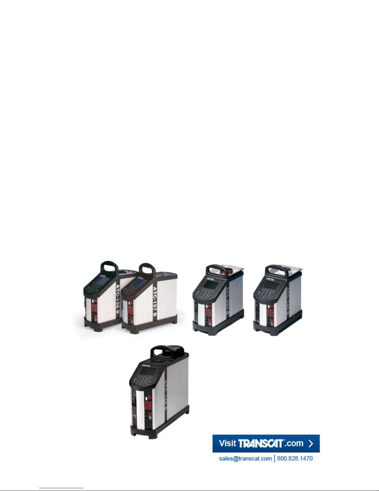
This reference manual applies to the following instruments:
JOFRA ATC-125 A - Cooling calibrator
JOFRA ATC-125 B - Cooling calibrator with input panel
JOFRA ATC-140 A - Cooling calibrator
JOFRA ATC-140 B - Cooling calibrator with input panel
JOFRA ATC-155 A - Cooling calibrator
JOFRA ATC-155 B - Cooling calibrator with input panel
JOFRA ATC-156 A - Cooling calibrator
JOFRA ATC-156 B - Cooling calibrator with input panel
JOFRA ATC-157 A - Cooling calibrator
JOFRA ATC-157 B - Cooling calibrator with input panel
JOFRA ATC-250 A - Heating calibrator
JOFRA ATC-250 B - Heating calibrator with input panel
JOFRA ATC-320 A - Heating calibrator
JOFRA ATC-320 B - Heating calibrator with input panel
JOFRA ATC-650 A - Heating calibrator
JOFRA ATC-650 B - Heating calibrator with input panel
Page 6

6 23-03-2009 105446 06
ISO-9001 certified
AMETEK Denmark A/S was ISO-9001 certified in September
1994 by Bureau Veritas Certification Denmark.
CE-label
Your new calibrator bears the CE label and
conforms to the EMC Directive and the Lowvoltage Directive.
Technical assistance
Please contact the dealer from whom you acquired the instrument
if you require technical assistance.
Warranty
According to current terms of sale and delivery.
This warranty only covers defects in manufacture and becomes
void if the instrument has been subject to unauthorised
intervention and/or misuse.
Page 7

105446 06 23-03-2009 7
2.0 Safety instructions
Read this manual carefully before using the
instrument!
In order to avoid any personal injuries and/or damage to
the instrument all safety instructions and warnings must be
observed.
Disposal – WEEE Directive
These calibrators contain Electrical and Electronic circuits
and must be recycled or disposed of properly (in
accordance with the WEEE Directive 2002/96/EC).
Warning……
About the use:
The calibrator must not be used for any purposes other
than those described in this manual.
The calibrator has been designed for interior use only
and should not be used in hazardous areas, where
vapour or gas leaks, etc. may constitute a danger of
explosion.
The calibrator must be kept free within an area of 20
cm on all sides and 1 metre above the calibrator.
Never use heat transfer fluids such as silicone, oil,
paste, etc. in the dry-block calibrators. These fluids may
penetrate the calibrator and cause damage or create
poisonous fumes.
The calibrator must be switched off before any
attempt to service the instrument is made.
When cleaning the well, REMEMBER to wear goggles
when using compressed air in the dry-block calibrator
and cleaning oil in the liquid bath calibrator.
Page 8

8 23-03-2009 105446 06
The ATC-125 contains the gases R-1270 and R-704
under pressure. The calibrator must under no
conditions be stored or operated at ambient
temperatures above 60C (140F). Doing so may cause
a hazard.
About the front panel:
For B versions only, the sockets on the input module
must NEVER be connected to voltages exceeding 5V
for the TC/RTD sockets and 45V for the mA/V sockets
proportional to ground. Thermostats must not be
connected to any other voltage sources during test.
About insertion tubes, insulation plugs, well and
sensor:
Never leave hot insertion tubes which have been
removed from the calibrator unsupervised – they may
constitute a fire hazard.
If you intend to store the calibrator in the optional
aluminium carrying case after use, you must ensure
that the instrument has cooled down to a temperature
below 100°C/212°F before placing it in the carrying
case.
About the fuses:
The fuse box must not be removed from the power
control switch until the mains cable has been
disconnected.
The two main fuses must be identical and correspond
to the chosen voltage.
About the liquid bath:
For liquid bath ensure that the sensor is absolutely
clean and dry as a few drops of water in the well (liquid
baths) might cause a steam explosion.
Do not pour cold fluid into a hot well – it might cause
an explosion.
Page 9
105446 06 23-03-2009 9
AMETEK Denmark A/S does not take any
responsibility, if the well is filled with other fluids than
those recommended.
Liquid baths should only be operated by trained
personal.
Heat transfer fluids must only be used in calibrators
prepared as a liquid bath. If these fluids are overheated
they will create noxious or toxic fumes. Proper
ventilation must be used.
Product information on the fluid must be carefully
investigated before use.
Do not handle hot fluid.
If the oil is heated beyond the flash point, it may
constitute a fire hazard.
Do not pour water or any other fluids into a bath filled
with hot oil, because only a few drops of water might
cause a steam explosion, if poured into 250°C hot oil.
Do not under any circumstances pour water on burning
oil. It might cause a dangerous steam explosion.
Caution – Hot surface
This symbol is engraved in the grid plate.
Do not touch the grid plate, the well or the insertion
tube when the calibrator is heating up – they may be
very hot.
Do not touch the lid or the spill tray when the calibrator
is heating up – they may be very hot (ATC-140/250 A/B
only).
Do not touch the tip of the sensor when it is removed
from the insertion tube/well – it may be very hot.
Do not touch the handle of the calibrator during use – it
may be very hot.
Page 10
10 23-03-2009 105446 06
Over 100°C/212°F
If the calibrator has been heated up to temperatures
above 100°C/212°F, you must wait until the instrument
reaches a temperature below 100°C/212°F before you
switch it off.
Caution – Cold surface
Below 0°C/32°F (applies only to the ATC-125/140/156/
157 A/B models)
Do not touch the well or insertion tube when these are
below 0°C/32°F - they might create frost-bites.
If the calibrator has reached a temperature below
0°C/32°F, ice crystals may form on the insertion tube
and on the well. This, in turn, may cause verdigris to
form on the material.
To prevent this from happening, the insertion tube and
the well must be dried. This is done by heating up the
calibrator to min. 100°C/212°F and any water left will
evaporate.
Remove the insulation plug while heating up.
It is very important that humidity in the well and insertion
tube is removed to prevent corrosion and frost
expansion damages.
Caution…
About the use:
Do not use the instrument if the internal fan is out of
order.
Before cleaning the calibrator, you must switch it off,
allow it to cool down and remove all cables.
About the liquid bath:
Be careful not to overfill the well with oil.
Avoid getting silicone oil on the clothes. It is impossible
to wash off. (ATC-140/250)
Page 11

105446 06 23-03-2009 11
The oil level rises several centimetres when the
temperature is rising. To stop overflow switch off the
main power and the oil level will decrease.
Carefully wipe off all silicone oil from the sensor under
test to avoid spreading of the silicone oil.
Be careful to select the right oil for the right task. Using
other than the recommended oils might cause damage
to the calibrator or degrade the performance.
Remove excess hot fluid with the outmost care, as it
might be very hot.
Do not attempt to remove hot fluid with the liquid
drainage tube, as it might melt.
About the well, insertion tube and sensor:
The well and the insertion tube must be clean and dry
before use.
Do not use any alkali, acid or ionic fluids in the
aluminium well as it might be damaged.
Scratches and other damage to the insertion tubes
should be avoided by storing the insertion tubes
carefully when not in use.
The insertion tube must never be forced into the well.
The well could be damaged as a result, and the
insertion tube may get stuck.
Before using new insertion tubes for the calibration, the
insertion tubes must be heated up to maximum
temperature – 250°C (482°F) / 320°C (608°F) / 650°C
(1202°F) - for a period of minimum 30 minutes (ATC250/320/650 A/B only).
The insertion tube must always be removed from the
calibrator after use.
The humidity in the air may cause corrosion oxidation
on the insertion tube inside the instrument. There is a
risk that the insertion tube may get stuck if this is
allowed to happen.
If the calibrator is to be transported, the insertion tube
must be removed to avoid damage to the instrument.
Page 12

12 23-03-2009 105446 06
The tip of the sensor should rest at the bottom of the
sensor basket for optimum results (liquid baths only).
Be careful not to submerge the handle or wire inlet of
the sensor-under-test in the fluid, as this might damage
the sensor (liquid baths only).
Note…
The product liability only applies if the instrument is
subject to a manufacturing defect. This liability becomes
void if the user fails to follow the instructions set out in this
manual or uses unauthorised spare parts.
Page 13
105446 06 23-03-2009 13
3.0 Setting up the calibrator
3.1 Receipt of the calibrator
When you receive the instrument…
Carefully unpack and check the calibrator and the accessories.
Check the parts against the list shown below.
If any of the parts are missing or damaged, please contact the
dealer who sold the calibrator.
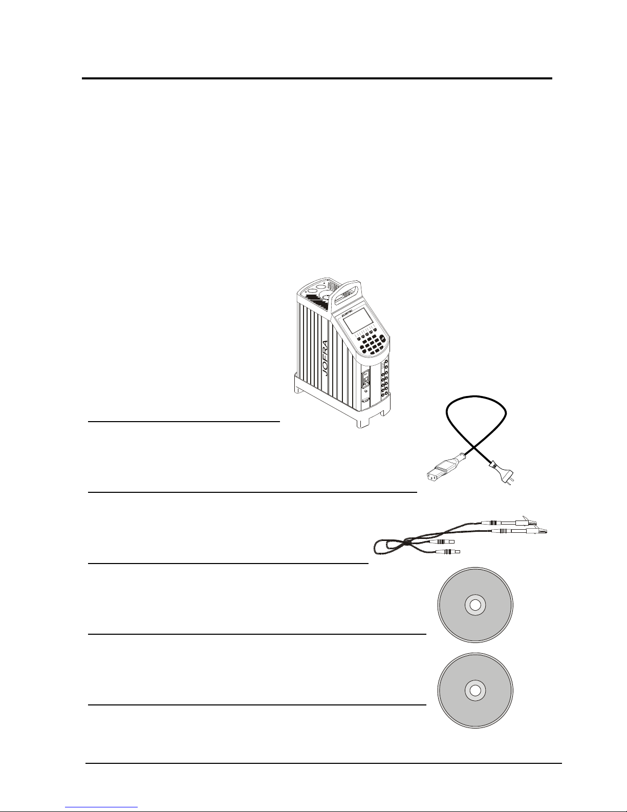
You should receive:
1 calibrator
1 mains cable
2 sets of test cables (2 black, 2 red –
B versions only)
1 CD-ROM containing software package
“JOFRACAL”
1 AMETRIM-ATC/DTI software package to
adjust the ATC series
7
1
4
8
2
5
0
9
3
6
i
E
S
C
_
C
A
L
I
B
R
A
T
I
O
N
I
N
S
T
R
U
M
E
N
T
S
Page 14
14 23-03-2009 105446 06
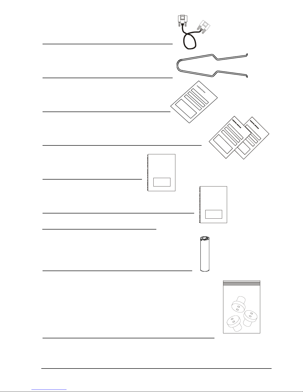
1 RS232 serial cable
1 tool for insertion tube
1 traceable certificate (A versions)
2 traceable certificates (B versions)
1 reference manual
1 user manual
ATC-125/156/157/320/650 A/B only
1 insertion tube (user specified)
3 pcs. insulation plugs for 6, 10, 16 mm sensors
(ATC-125/156 A/B only)
or
3 pcs. insulation plugs for 5, 8, 11 mm sensors
(ATC-157 A/B only)
Referen ce Manual
User Manu al
Page 15
105446 06 23-03-2009 15
Dow corning
Material data sheet
O
i
l
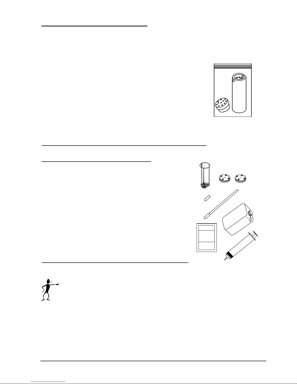
ATC-140/250 A/B only (dry-block)
1 dry block kit – metric consisting of :
- 1 insertion tube, multi-hole, metric, with
11 bores (incl. reference bore)
- 1 pcs. insulation plug for multi-hole,
metric (ATC-140 A/B only)
or
1 dry block kit – inch consisting of :
- 1 insertion tube, multi-hole, inch, with 11
bores (incl. reference bore)
- 1 pcs. insulation plug for multi-hole, inch
(ATC-140 A/B only)
ATC-140/250 A/B only (liquid bath)
1 liquid bath kit consisting of :
- 1 sensor basket
- 2 lids for transportation /
calibration
- 1 stirring magnet
- 1 stirring magnet remover
- 1 liquid drainage syringe
- 1 silicone oil
- 1 oil material safety data sheet
When reordering, please specify the parts number
found in the list of accessories, chapter 9.0.
Page 16
16 23-03-2009 105446 06
3.2 Preparing the dry-block calibrator
The ATC-B-version has a precision reference input. To achieve the
high precision, a set of sensor coefficients relating to the specific
sensor must be present in the ATC. Before use of the ATC, ensure that
the correct coefficients in the ATC are equal to those from the sensors
calibration certificate. This is done with the PC software JOFRACAL
included on the CD. Please read how to do in the chapter “Reference
Sensors” in the JOFRACAL user manual on the CD.
Warning
The calibrator must not be used for any purposes other
than those described in this manual.
The calibrator has been designed for interior use only
and should not be used in hazardous areas, where
vapour or gas leaks, etc. may constitute a danger of
explosion.
The calibrator must be kept free within an area of 20
cm on all sides and 1 metre above the calibrator.
The ATC-125 contains the gases R-1270 and R-704
under pressure. The calibrator must under no
conditions be stored or operated at ambient
temperatures above 60C (140F). Doing so may cause
a hazard.
Note…
The instrument must not be exposed to draughts.
Page 17
105446 06 23-03-2009 17
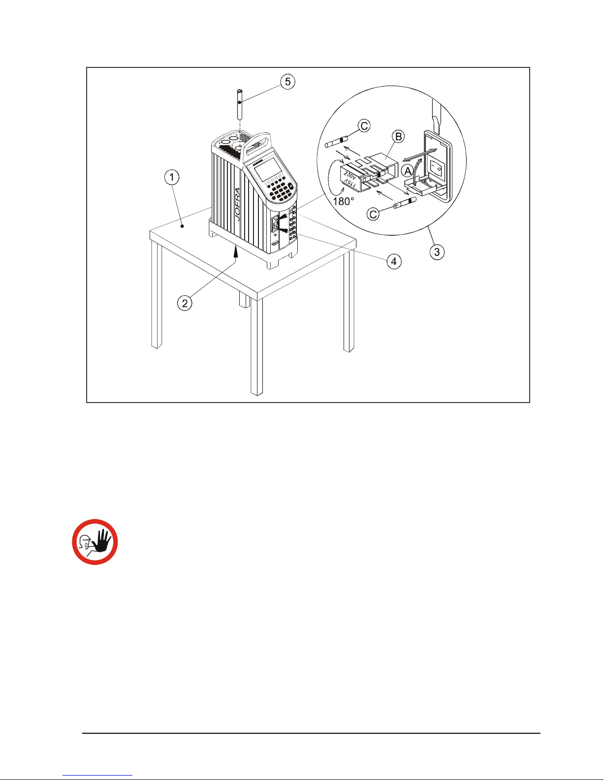
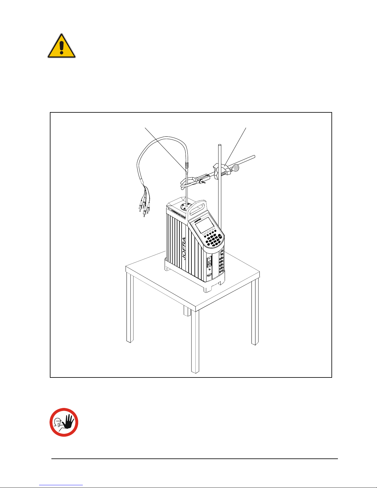
Fig. 1a
3.2.1 When setting up the dry-block calibrator, you must…
Place the calibrator on an even horizontal surface where you
intend to use it.
Caution…
Do not use the instrument if the internal fan is out of
order.
Ensure a free supply of air to the internal fan located at the
bottom of the instrument.
The area around the calibrator should be free of draught, dirt,
flammable substances, etc.
7
1
4
8
2
5
0
9
3
6
i
E
S
C
_
.
F
1
F
3
F
4
F
5
F
2
C
A
L
I
B
R
A
T
I
O
N
I
N
S
T
R
U
M
E
N
T
S
Page 18

18 23-03-2009 105446 06
Check the voltage on the power control switch (on/off switch
(230V/115V)). If the voltage of the power control switch
differs from the line voltage, you must adjust the setting of
the power control switch as follows (see fig. 1a):
A. Open the fuse box lid using a screwdriver.
B. Take out the fuse box.
C. Remove both fuses replacing them with two new fuses.
These must be identical and should correspond to the
line voltage. See chapter 9.0.
B. Turn the fuse box 180° and slide it back into place.
Check that the earth connection for the instrument is present
and attach the cable.
Select an insertion tube with the correct bore diameter. See
section 3.2.2 for information on how to select insertion tubes.
The calibrator is now ready for use.
Page 19

105446 06 23-03-2009 19
3.2.2 Choice of insertion tube
Caution…
Before using new insertion tubes for calibration, the
insertion tubes must be heated up to maximum temperature
- 250°C (482°F) / 320°C (608°F) / 650°C (1202°F) - for a
period of minimum 30 minutes.
In order to ensure the best calibration of your sensors
please avoid using insertion tubes in the ATC-320
calibrator, which have been used in the ATC-650 calibrator.
Insertion tubes are selected on the basis of the diameter of the sensor
to be calibrated.
Use the table for insertion tubes in chapter 9.0 to find the correct part
number.
Alternatively, you may order an undrilled insertion tube and drill the
required hole yourself. The finished dimensions should be as follows:
Sensor diameter +0.2
+0.05/-0 mm.
In order to get optimum results and preventing ice from building up in
the well of the cooling calibrators, a proper sized insulation plug must
be placed over the well during the calibration process.
The holes in the plug must have a tight fit and unused holes must be
covered using e.g. EPDM plugs (spare part no. 126280).
Page 20

20 23-03-2009 105446 06
3.1.3 Inserting the sensors
Before inserting the sensors and switching on the calibrator, please
note the following important warning:
Warning
Never use heat transfer fluids such as silicone, oil,
paste, etc. in the dry-block calibrator.
These fluids may penetrate the calibrator and cause
damage or create poisonous fumes.
Insert the sensors as shown in fig. 2a.
Fig. 2a
7
1
4
8
2
5
0
9
3
6
i
E
S
C
_
.
F
1
F
3
F
4
F
5
F
2
C
A
L
I
B
R
A
T
I
O
N
I
N
S
T
R
U
M
E
N
T
S
Reference sensor
(if available)
Sensor under test
Insertion tube
Page 21
105446 06 23-03-2009 21
Caution…
The well and the insertion tube must be clean before
use.
Scratches and other damage to the insertion tubes
should be avoided by storing the insertion tubes
carefully when not in use.
The insertion tube must never be forced into the well.
The well could be damaged as a result, and the
insertion tube may get stuck.
Caution – Hot surface
Do not touch the grid plate, the well or the insertion
tube while the calibrator is heating up – they may be
very hot.
Do not touch the tip of the sensor when it is removed
from the insertion tube – it may be very hot.
Do not touch the handle of the calibrator during use –
it may be very hot.
Caution – Cold surface
If the calibrator has reached a temperature below
0°C/32°F, ice crystals may form on the insertion tube and
on the well. This, in turn, may cause verdigris to form on
the material.
To prevent this from happening, the insertion tube and the
well must be dried. This is done by heating up the
calibrator to min. 100°C/212°F and any water left will
evaporate.
Remove the insulation plug while heating up.
It is very important that humidity in the well and insertion
tube is removed to prevent corrosion and frost expansion
damages.
Do not touch the well or insertion tube when these are
below 0°C/32°F – they can create frost-bites.
Page 22
22 23-03-2009 105446 06
3.3 Preparing the liquid bath calibrator
Warning
The calibrator must not be used for any purposes other
than those described in this manual.
The calibrator has been designed for interior use only
and should not be used in hazardous areas, where
vapour or gas leaks, etc. may constitute a danger of
explosion.
Liquid baths should only be operated by trained
personal.
AMETEK Denmark A/S does not take any
responsibility, if the well is filled with other fluids than
those recommended.
Heat transfer fluids must only be used in calibrators
with an liquid bath. If these fluids are overheated they
will create noxious or toxic fumes. Proper ventilation
must be used.
Product information on the fluid must be carefully
investigated before use.
The calibrator must be kept free within an area of 20
cm on all sides and 1 metre above the calibrator.
Note…
The instrument must not be exposed to draughts.
Page 23
105446 06 23-03-2009 23
7
1
4
8
2
5
0
9
3
6
i
E
S
C
_
.
F
1
F
3
F
4
F
5
F
2
C
A
L
I
B
R
A
T
I
O
N
I
N
S
T
R
U
M
E
N
T
S
Reference sensor
(if available)
1
2
4
5
7
9
3
6
8
O
i
l
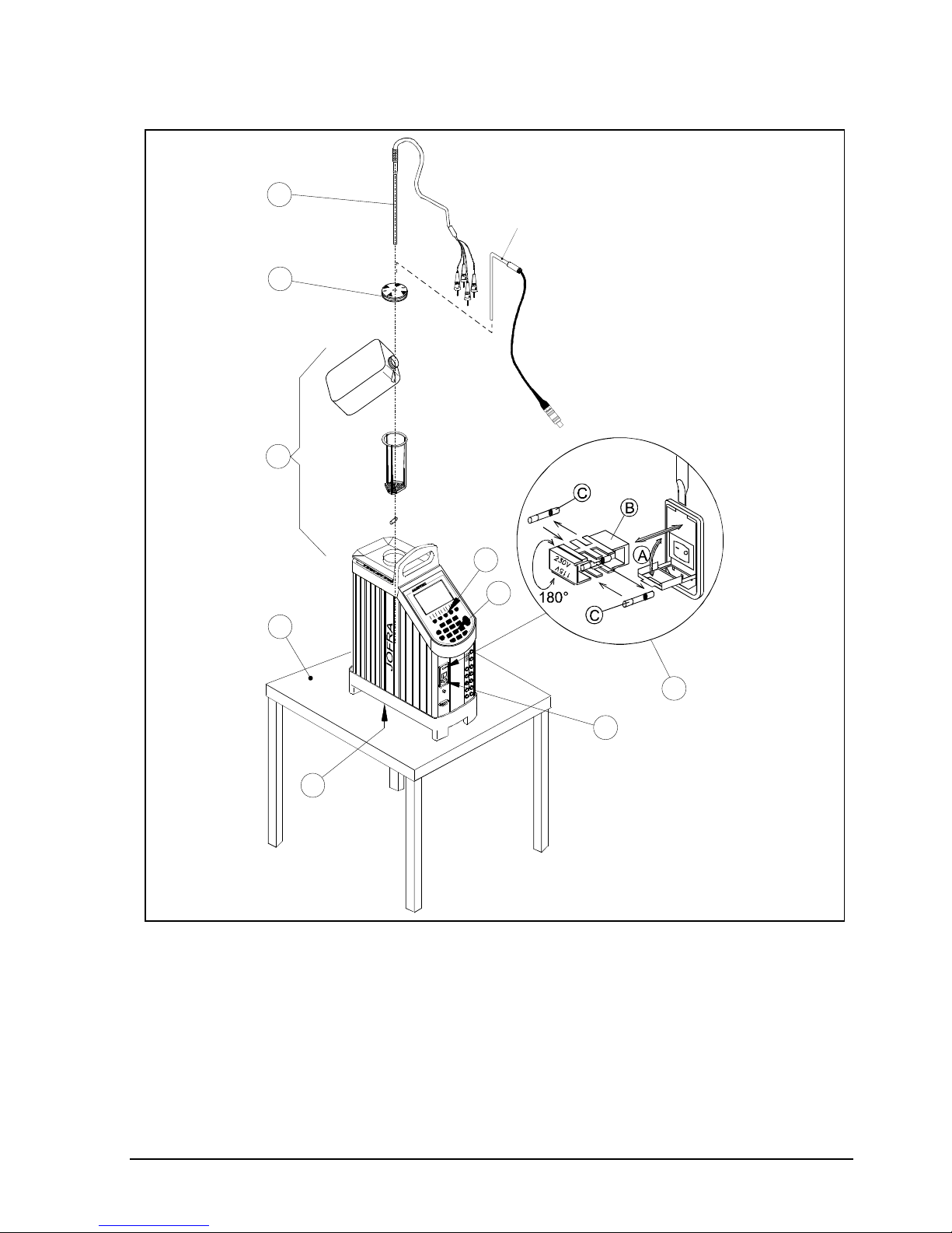
Fig. 1b
3.3.1 When setting up the liquid bath calibrator, you must…
Place the calibrator on an even horizontal surface where you
intend to use it. Place it in a way that will minimize the risk of
tilting.
Page 24

24 23-03-2009 105446 06
Caution…
Do not use the instrument if the internal fan is out of
order.
The well must be clean before use.
Ensure a free supply of air to the internal fan located at the
bottom of the instrument.
The area around the calibrator should be free of draught, dirt,
flammable substances, etc.
Check the voltage of the power control switch (on/off switch
(230V/115V)). If the voltage of the power control switch
differs from the line voltage, you must adjust the setting of
the power control switch as follows (see fig. 1b):
A. Open the fuse box lid using a screwdriver.
B. Take out the fuse box.
C. Remove both fuses and insert two new fuses.
These must be identical and should correspond to the
line voltage. See chapter 9.0.
B. Turn the fuse box 180° and slide it into place.
Check that the earth connection for the instrument is present
and attach the cable.
Place the parts from the liquid bath kit in the well in the
following order:
Stirring magnet – It is very important that the stirring
magnet is in place and spinning before any calibration is
attempted. The stirring magnet ensures minimum
temperature gradient in the fluid. The magnets teflon
cover will over time be worn down, leaving the magnet
flat on one side. This will reduce the spinning ability. A
magnet with a flat side must therefore be replaced.
Sensor basket – It is very important to place the sensor
basket in the well, as it ensures that the sensors
encounter maximum temperature stability and ensures
that the stirring magnet is not blocked.
Page 25
105446 06 23-03-2009 25
Silicone oil – Fill the well with oil according to the
tables of recommended oil volume. The recommended
volumes must be adjusted to the actual job.
For oil tables and further oil information – see section
3.3.2.
The sensor basket is marked with an optimum fluid level
mark (100%). When filling the well with fluid and placing
the sensors, this mark must never be exceeded.
Warning
Do not pour cold fluid into a hot well – it might cause an
explosion.
Do not pour water or any other fluids into a bath filled
with hot oil, because only a few drops of water might
cause a steam explosion, if poured into e.g. 250°C hot
oil.
Caution…
Do not use any alkali, acid or ionic fluids in the aluminium
well as it might be damaged.
Be careful not to overfill the well with oil.
The oil level rises several centimetres when the
temperature is rising to maximum. To stop the overflow
switch off the main power and the oil level will decent.
Remove excess hot fluid with the outmost care, as it might
be very hot.
Do not attempt to remove hot fluid with the liquid drainage
syringe, as it might melt.
Start the stirring magnet by following the procedure in section
4.8.7.
Place the calibration lid onto the well. See section 3.3.3 for
drilling information.
Select a SET-temperature according to the tables of
recommended oil volume by following the procedure in
section 4.4.
Page 26
26 23-03-2009 105446 06
7
1
4
8
2
5
0
9
3
6
i
E
S
C
_
.
F
1
F
3
F
4
F
5
F
2
C
A
L
I
B
R
A
T
I
O
N
I
N
S
T
R
U
M
E
N
T
S
Support rod set
Sensor under test
Warning
Ensure that the sensor is absolutely clean and dry, as a few
drops of water might cause a steam explosion.
Place the sensor to be calibrated vertically into the well. It is
recommended to use the optional support rod set for a
correct position during calibration. See fig. 2b.
Fig. 2b
Caution…
The tip of the sensor should rest at the bottom of the
sensor basket for optimum results.
Page 27

105446 06 23-03-2009 27
Be careful not to submerge the handle or wire inlet of the
sensor-under-test in the fluid, as this might damage the
sensor.
The calibrator is now ready for use.
3.3.2 Selection of fluids
Caution…
Be careful to select the right fluid for the right task. Using
other than the recommended fluids might cause damage
to the calibrator or degrade the performance.
AMETEK Denmark A/S recommends DOW CORNING 200(R) oil 10cSt
for sub zero temperatures to 140°C and DOW CORNING 200(R) oil
50cSt for ambient temperature to 250°C. Technical specifications for
the liquid baths has been produced using the fluids mentioned above.
For proper handling, use and disposal of fluid – read fluid product
information. When reading this information pay special attention to
details regarding fume point, flash point, boiling point and point of
decomposition.
When the fluid temperature approaches the fume point, it is necessary
to use proper ventilation. An exhaust hood is recommended. When
ventilation is applied take care not to expose the calibrator to
alternating draft, as it might influent the temperature stability. If
possible make the ventilation flow as constant as possible.
At low temperatures the viscosity of the fluid can constitute a problem.
When the viscosity becomes to low, the stirring magnet can’t provide
proper circulation in the well to maintain temperature uniformity.
Therefore it is essential to investigate the physical property of the fluid
before one is selected.
Page 28
28 23-03-2009 105446 06
Tables of recommended oil level @23°C well temperature
ATC-250 A/B ATC-140 A/B
For recommended
50 cSt oil
For recommended
10 cSt oil
0°C - 50°C 100%
-20°C - 50°C 100%
50°C - 100°C 95%
50°C - 100°C 95%
100°C - 150°C 90%
100°C - 140°C 90%
150°C - 200°C 85%
200°C - 250°C 80%
For the best result, the oil should be in good condition and free of
foreign objects. If water is accumulated in the oil due to melted ice
crystals – the oil must be dried out, by heating it up.
Warning
Do not handle hot fluid.
If the fluid is heated beyond the flash point, it may
constitute a fire hazard.
If the fluid has caught fire, switch off the main power to prevent further
heating of the fluid. Flames are best extinguished by cowering the well
with a non-flammable lid.
Warning
Do not under any circumstances pour water on burning oil. It
might cause a dangerous steam explosion.
3.3.3 Handling of lids
It is strongly recommended to leave the lid on during calibration.
Calibration without the lid may affect the temperature stability and
homogeneity.
Page 29

105446 06 23-03-2009 29
To be able to use the lid for calibration, holes must be drilled in to it, in
order to fit your calibration needs. If you use many different sizes of
sensors more lids can be purchased at your JOFRA supplier.
It is advisable to drill the holes at the same size as the sensors plus
0,5mm and distribute the holes evenly over the lid.
3.3.4 Inserting the sensors
Be sure that the sensors can be calibrated in fluid. E.g. certain ceramic
sensors might be destroyed.
Caution…
The insertion tube must be clean before use.
Scratches and other damage to the insertion tubes
should be avoided by storing the insertion tubes
carefully when not in use.
Carefully wipe off all silicone oil from the sensor-under-
test to avoid spreading of the silicone oil.
Caution – Hot surface
Do not touch the lid or the spill tray when the calibrator
is heating up – they may be very hot.
Do not touch the tip of the sensor when it is removed
from the well – it may be very hot.
Do not touch the handle of the calibrator during use –
it may be very hot.
Page 30
30 23-03-2009 105446 06
4.0 Operating the Calibrator
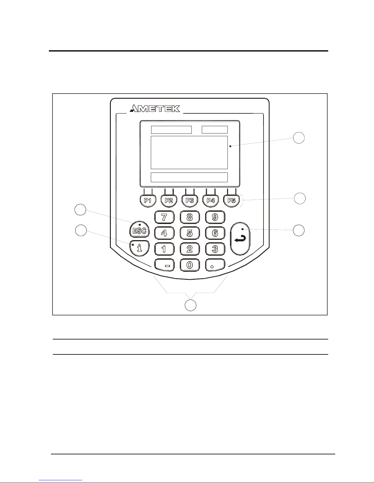
4.1 Keyboard, display and standard connections
Keyboard
Fig. 3
Pos. Description
LCD.
SOFT KEYS used to select menu options displayed in the
LCD.
ENTER KEY used to accept selected options or entered
values.
NUMERIC KEYS used to type in values.
CALIBRA T IO N INSTRUMENTS
1
2
33
4
5
6
(heading) (icon)
(information)
(functions)
Page 31

105446 06 23-03-2009 31
INFORMATION KEY used to display the status of the
parameters involved with the function currently selected.
ESC KEY (escape key) used to cancel a selection/edit or
return to previous menu.
Display
Fig. 4
The Display is divided into four separate areas:
Heading: Informs you of the current function selected.
Icon: Indicates graphically the status of the calibrator
Information: Provides the bulk of information and data in the
selection.
Functions: Informs you of the soft keys functions.
(heading) (icon)
(information)
(functions)
Page 32

32 23-03-2009 105446 06
Standard connections (all versions)
Fig. 5
Pos. Description
Power control switch with a cable connection and on/off
switch. It also contains the main fuse. See section 6.1 for
information on how to change the fuses and section 3.2.1
to adjust the voltage setting of the power control switch.
Connection for synchronization output.
The state of the synchronization output is determined by
the READ or TRUE temperature (dependent on the choice
of reference sensor) by the following guidelines:
When the extended stability time is = 0 minute, the
relay is switched on for 2 seconds, when stability is
achieved.
When the extended stability time 1 minute for the
internal reference sensor (READ), the relay is switched
on in the last minute of the extended stability time.
Sync.
230V 5AF/115V 10AF
115 V
Fuse
RS232
1
2
3
Page 33

105446 06 23-03-2009 33
Connection for RS232 communication.
4.2 Input module (B versions only)
Warning
The sockets on the input module must NEVER be
connected to voltages exceeding 5V for the TC/RTD
sockets and 45V for the mA/V sockets proportional to
ground.
Thermostats must not be connected to any other
voltage sources during test
Description of sockets for external connections
Fig. 6
7
6
5
4
3
2
1
8
Ref. Inpu t
V
mA Pas.
mA Act.
45V MAX
Switch Test
5V MAX
TC
+
-
+
-
+
-
+
-
+
-
.
.
Page 34

34 23-03-2009 105446 06
Pos. Description
Input for RTD sensor (2, 3 or 4 wire).
Connection to chassis (earth/ground).
Input for reference sensor.
Voltage input.
Passive mA input.
Active mA input with 24V supply for transmitter.
Connection for thermostat test.
Note that this connection is for dead switches.
TC connection for thermocouples.
One of the inputs either
, , , or can be selected
displaying the “SENSOR” temperature in the Setup and
can be
displayed as “TRUE” temperature.
Note: Only the sensor type, which is to be tested, should be connected
to the input panel.
4.3 Display readouts
Switch on the calibrator using the power control switch (pos.
1 in fig. 5). The start up menu is displayed for approximately
2 seconds and is then replaced with the main menu screen:
Page 35

105446 06 23-03-2009 35
The functions are available using the soft keys and are
described in sections 4.4 to 4.8.
4.3.1 Main screen temperature values
Two temperatures are displayed (A and B versions):
READ temperature: This is the temperature measured by the
internal reference sensor.
SET temperature: This is the target temperature for the well. SET
temperature displays the last value entered. If no value has been
entered previously, "Not Activated" is displayed.
Additional temperatures displayed (B versions only):
SENSOR temperature: This is the temperature measured by the
sensor being measured.
TRUE temperature: This is the temperature measured by an
external reference sensor. This is only displayed when an external
reference sensor is used and replaces READ temperature.
4.3.2 Stability of temperature values
The stability of the READ, TRUE and SENSOR temperatures are
indicated by the following messages:
"Not stable": Indicates that the measured temperature is not yet
within the specified stability criteria.
"Time to stable": Indicates that the temperature changes are within
the specified stability criteria (see chapter 8.0) and states a time (in
minutes) when the stable situation can be achieved.
"": Indicates that the “stable” situation is achieved.
SENSOR temperature cannot indicate "" unless the
READ or the TRUE temperature is stable.
If External reference (TRUE) is selected, the stability
criteria will refer to this. As default the criteria are as
follows:
Page 36

36 23-03-2009 105446 06
The temperature must be within a range of ±0.03°C/
0.05°F in 10 minutes to be stable.
The criteria can be changed, however, if the temperature
stability criteria is set wider or the stability time is set
shorter, the calibrator may not reach the SET
temperature.
4.4 SET temperature menu
Press
. A cursor appears in the SET temperature field.
Use the numeric keys to enter a new value, or
to edit the
existing value.
Press
to accept the value and return to the main menu
screen.
4.5 Calibration menu
Note…
This Calibration function is for B versions only.
This function enables you to perform automatic calibrations of multiple
temperature sensors. The calibration procedure is semi-automatic,
using parameters and settings which are defined in work orders. These
work orders are created and edited using the "JOFRACAL" PC
program. If multiple calibrations, using identical or similar settings, are
required, the work orders can be replicated in the calibrator and
labelled with a unique name.
Press
to select the Calibration menu.
Page 37

105446 06 23-03-2009 37
F3F2 F4 F5F1
Note: Calibration information is available in several places
throughout the calibration menus. The content of this
information is described in section 4.5.3.
4.5.1 Running a calibration
Press
to select the Run calibration menu.
F3F2 F4 F5F1
Use
and to scroll through the list and highlight an
existing work order.
Press
to continue the calibration using the highlighted
work order
or,
Press
to create a copy of the work order. Then press
to accept the new name. (Copies have the same name as
the original work orders, but contain a suffix number, making
the name unique.)
Page 38

38 23-03-2009 105446 06
F3F2 F4 F5F1
Press
to continue the calibration without editing the basic
parameters
or,
Press
to start the editor.
F3F2 F4 F5F1
Make the necessary changes, exit the editor by pressing
and continue the calibration by pressing
.
If the sensor under test is a thermocouple sensor and the
manual compensation mode is selected in work orders, a cold
junction temperature must be defined.
Page 39

105446 06 23-03-2009 39
Default value is 0,00C (32F) as if an ice bath is available.
Otherwise press
to enter another value.
Make the
necessary changes, exit the editor by pressing
and
continue the calibration by pressing
.
F3F2 F4 F5F1
Press
if you wish to overwrite the existing calibration and
continue.
If the work order is defined as a manual input,
or
are
used to determine when the values are to be entered.
– to enter values during the calibration.
– to enter values after the calibration.
Follow the instructions on screen to connect the sensors and
press
to start the calibration.
Page 40

40 23-03-2009 105446 06
The calibration can be stopped at any time, but this will erase
all the calibration data.
Follow the instructions on screen for repositioning the
sensors (if an external manual heat source is used) and
entering the step values (if manual input is required).
When the calibration is complete, press
or to store the
results in the calibrator. The results can be viewed using the
instructions in section 4.5.2.
4.5.2 Showing calibration results
Press
to select the Show calibration menu.
F3F2 F4 F5F1
Use
and to scroll through the list and highlight a
specific work order.
Press
to display the calibration details for the selected
work order.
The calibration results can be uploaded with the “AmeCal
Temperature” PC program. This enables you to print out the
results on a certificate.
Calibration result details
This screen enables you to scroll through the calibration steps and
view the actual SET, READ/TRUE and SENSOR temperatures for the
individual calibration steps, together with the deviation and Pass/Fail
status.
Page 41

105446 06 23-03-2009 41
Press
to exit the calibration details and return to the
Show calibration results menu.
4.5.3 Displaying calibration information
Calibration information is defined within the work orders created on the
PC using "JOFRACAL". This information is divided in to six pages of
information:
Use
and to scroll through the pages.
The scroll wraps around, allowing you to go from page 6 to page 1 and
vice versa.
Page 42

42 23-03-2009 105446 06
Scenario (page 1)
This shows the calibration setup in a graphic format. The parameters
for this setup are defined in the work order created using the PC
program.
Basic parameters (page 2)
This informs you how the calibration was registered, either "as found"
or "as left" and the ambient air temperature (entered manually) at the
time of the calibration.
Notes (page 3)
Information entered via the PC program, when the work order is
created.
Sensor under test (page 4)
If a Digital Temperature Indicator (DTI) is used, the "Measurement"
field will display the DTI channel used.
External reference sensor (page 5)
This screen is only available when an external reference sensor is
used. If a DTI is used, the "Measurement" field will display the DTI
channel used.
Calibration procedure (page 6)
This shows the pre-defined temperature steps for the calibration.
4.6 Switch test menu
Note…
This Switch test function is for B versions only.
Switch test automatically locates the switch temperatures of a
thermostat.
Three parameters are required:
Start temperature (T
1
)
End temperature (T
2
)
Rate of change in temperature (slope rate).
Page 43

105446 06 23-03-2009 43
Hysteresis of a thermostat can also be determined here. Where the
hysteresis determines the tolerence between the upper switch
temperature and the lower switch temperature of the thermostat.
Fig. 7
Press
in the main menu to select the Switch test menu.
F3F2 F4 F5F1
Two functions are available using the soft keys
Calibrator stable
Shifting temperature
Calibrator stable
Heating with Slope Rate
T
Cooling with Slope Rate
T
T
Expected switch range
for thermostat
Calibrator stable
t
[min]
T [°C/°F]
T
T
T
T
T
2
Open
Close
1
Star t
Open
Close
Hyste
Page 44

44 23-03-2009 105446 06
4.6.1 Running a switch test
Press
to select Run switch test.
F3F2 F4 F5F1
The small graph illustrates the current T
1
, T2 and hysteresis
selections. Note that T
1
can be greater than T
2
.
Press a function soft key (
– ) to enable the editor.
– To edit the first set temperature (T
1
).
–
To edit the second set temperature (T
2
).
–
To determine hysteresis, toggle between "Yes" (a two
temperature measurement) and "No" (a single
temperature measurement).
–
To edit the slope rate. The permitted range is 0.1 –
9.9°C/min. / 0.2 – 17.8°F/min.
Note: the slope rate should be set so that the
thermostat sensor can follow the temperature in the
calibrator's well.
Make the necessary changes and exit the editor by pressing
.
Press
to start the switch test.
While the switch test is in progress, three functions are
available:
– To show the current switch test results. This is
described in section 4.6.2.
– To review the switch test set up (no editing is
possible).
– To stop the switch test.
Page 45

105446 06 23-03-2009 45
The calibrator's switch test procedure
1. Once the switch test is started, the calibrator starts working towards
T
1
as quickly as possible. The calibrator's temperature changes
(heating or cooling) and switch status are shown in the display.
2. When T
1
is achieved and the temperature is stable, a "" is
displayed for one second.
3. The calibrator now starts working towards T
2
at the specified slope
rate.
4. In a normal situation, the thermostat changes state before T
2
is
achieved. If T
2
is achieved and the temperature is stable, "No Shift"
result is displayed.
5. When hysteresis is not selected (single temperature change), the
finished switch test result is displayed, see section 4.6.2.
When hysteresis is selected (two switch changes), the calibrator
starts working towards T
1
at the specified slope rate.
6. Normally, the thermostat changes state before T
1
is achieved. If T1
is reached and the temperature is stable, "No Shift" result is
displayed.
7. The finished switch test results are displayed, see section 4.6.2.
4.6.2 Showing switch test results
Two types of switch test results are available:
Results during a switch test.
Results of a finished switch test.
Page 46

46 23-03-2009 105446 06
Results during a switch test
Press
to select Show result.
F3F2 F4 F5F1
This shows the results that are currently available. These
results change as the test progresses.
Press
to return to the switch test.
Finished switch test results
At the end of a switch test the results are displayed. These show the
final result of the test and are known as the finished results.
F3F2 F4 F5F1
Note: A hysteresis value is only displayed when hysteresis is selected.
If either the first or second temperature displays "No shift", hysteresis
displays "Error". For details, see chapter 6.0.
When you exit the switch test, either by pressing
or
, these
results are stored in the calibrator's memory.
By pressing
the results are not stored in the calibrator’s memory.
Page 47

105446 06 23-03-2009 47
To view stored finished switch test results
Press
to select Show results.
F3F2 F4 F5F1
Press a function soft key (
– ) to select the results for
one of the last five tests. The data in the information field is
the same as that displayed at the end of the switch test.
4.7 Auto step menu
Auto step is used to step automatically between a range of different
calibration temperatures. This is useful when calibrating sensors in
places that are difficult to reach and sensors where the output is
displayed in a different location.
Fig. 8
Temperature stable
Calibrator starts working towards next temperature
t
T
T
T
T
T
T [°C/°F]
Time
[min]
Sta rt
1
2
3
4
Page 48

48 23-03-2009 105446 06
Press
to select the Auto step menu.
F3F2 F4 F5F1
Two functions are available using the soft keys
4.7.1 Running an Auto step calibration
Press
to select Run auto step.
F3F2 F4 F5F1
Press
to enable the editor to change the Auto step setup
and step temperature values.
No of steps: the number of temperature steps per
direction (T
1
Tx) can be set using integers from 1 – 20.
When a Two-way mode is selected, the same number of
steps are used for the second direction (T
x
T1).
Mode: toggle between "One-way" and "Two-way".
Hold time: defines the time (in minutes) the temperature
is maintained (after it is stable) for each step.
T step values: must be set within the sensors permitted
range.
Page 49

105446 06 23-03-2009 49
Make the necessary changes and exit the editor by pressing
.
Press
to start the Auto step test.
While the step test is in progress, several functions are
available:
– To review the Auto step result (no editing is possible).
– To pause the test.
and – Force the test to jump a step (previous or next),
regardless of the temperature step's stability.
– To stop the Auto step test.
When the Auto step test is complete the results are
displayed. Press
or to finish the test and store the
results in the calibrator. The results can be viewed using the
instructions in section 4.7.2.
By pressing
the results are not stored in the calibrator’s
memory.
4.7.2 Auto step test results
At the end of a Auto step test the results are displayed and stored in
the calibrators memory.
F3F2 F4 F5F1
The measured READ or TRUE and SENSOR temperatures for each
step are displayed.
Page 50

50 23-03-2009 105446 06
To view stored switch test results
Press
to select Show results.
F3F2 F4 F5F1
Press a function soft key (
– ) to select one of the last
five Auto step tests stored in the calibrator.
Page 51

105446 06 23-03-2009 51
4.8 Setup menu
Press
to select the Setup menu.
Nine fuctions are available. These are divided into three
separate pages. Use the function key(s) labelled "more" to
change page. Use the soft keys (
– ) to select the
individual functions:
page 1
page 2
page 2 (ATC-140/250 A/B
only)
page 3
page 3 (ATC-140/250 A/B
only)
F3F2 F4 F5F1
4.8.1 Loading a setup
Loading a setup causes all the parameters in the setup menu
being to be overwritten.
Page 52

52 23-03-2009 105446 06
Press
(setup page 1) to select Load setup.
Use the keyboard to select a calibrator setup number (1–9).
Press
to load the selected setup. A warning informs you
that the active setup will be overwritten.
Press
if you are sure you want to overwrite the existing
setup and return to the setup menu.
4.8.2 Saving a setup
Saving a setup, saves all the parameters in the Setup menu.
Press
(setup page 1) to select Save setup to registry.
Use the keyboard to select a register number (1–9).
Press
to save the current setup in the selected register
and return to the setup menu.
4.8.3 Adjusting the display contrast
Press
(setup page 1) to select Display contrast.
Press
to make the display darker or to make the
display lighter.
Press
to accept the new setting and return to the setup
menu.
4.8.4 Altering temperature display settings
Press
(setup page 1) to select the Temperature menu.
Page 53

105446 06 23-03-2009 53
F3F2 F4 F5F1
Use the function soft keys to set the parameters displayed.
Setting the temperature units
Press
to select Unit.
Press a function soft key to select the temperature units:
- To select Celsius.
- To select Fahrenheit.
- To select Kelvin
Press
to accept the new setting.
Setting the temperature resolution
Press
to select temperature resolution.
F3F2 F4 F5F1
Press a function soft key (
– ) to select the temperature
type.
Press a function soft key to set the resolution.
– 1° resolution.
– 0.1° resolution.
Page 54

54 23-03-2009 105446 06
– 0.01° resolution.
Press
to accept the new setting and return to the
temperature resolution menu.
Setting the max. SET temperature
Press
to select Max. SET temperature.
Press
. A cursor appears in the Max. SET temperature
value.
Use the numeric keys to enter a new value, or press
to
edit the existing value.
Press
to accept the new setting and return to the Max.
SET temperature menu.
Converting electrical inputs to temperatures
Press
to select the Conversion to temperatures menu.
F3F2 F4 F5F1
Setting voltage or current input conversions from the electric
signal to a temperature reading.
Press a function soft key (
– ) to select the type of
input.
Press a function soft key to select a parameter and start the
editor.
– Low input (voltage or current).
Page 55

105446 06 23-03-2009 55
– Low input temperature that corresponds to the low
level electrical signal.
– High input (voltage or current).
– High input temperature that corresponds to the high
level electrical signal.
Use the numeric keys to set a new value or press
to edit
the existing value.
Make the necessary changes and press
to accept the new
setting(s), and to return to the Conversion to temperatures
menu.
Setting cold junction compensation temperatures
When the automatic mode is selected, the calibrator
measures the temperature in the T/C connector and uses this
for the cold junction compensation of the thermocouple.
Press
to select Cold junction compensation.
Press a function soft key to enable the editor:
- To select compensation mode; toggle between
Automatic and Manual.
- To define a Manual temperature for the cold junction
compensation. This can be used when an external cold
junction temperature can be established.
Make the necessary changes and press
to accept the new
setting(s) and return to the Cold junction compensation
menu.
4.8.5 Setting the sensor input parameters (B versions only)
Press
(setup page 2) to select Input.
Page 56

56 23-03-2009 105446 06
F3F2 F4 F5F1
Selecting the reference sensor input
Press
to select Reference sensor.
Press a function soft key to enable the editor:
- To select Internal reference source. Results in
displaying the reference as READ.
- To select External reference source (reference input
on front panel). Results in displaying the reference as
TRUE and the Internal reference is displayed as READ
(a secondary value).
Check that the displayed serial number is the same, as
on the reference sensor – otherwise the sensors
coefficients need to be downloaded to the ATC. This is
done with the PC software JOFRACAL included on the
CD. Please read how to do in the Chapter “Reference
Sensors” in the JOFRACAL user manual on the CD.
- To change Convert to temperature function.
Yes sets the readout of the External reference as a
temperature.
No sets the readout of the External reference in
values.
- To change SET follows TRUE; toggle between On and
Off.
This function enables you to reach an exact TRUE
temperature measured by the External reference
sensor.
Page 57

105446 06 23-03-2009 57
Note that when ON is selected, the calibrator will let
the temperature be set by the TRUE temperature. This
means it will take longer before the calibrator indicates
stable.
Note: Set follows TRUE is only relevant when the
External reference sensor is displayed in temperature
units.
Make the necessary changes and press
to accept the
new setting(s) and return to the Input menu.
Note that when SET follows TRUE is on, it is indicated by a
-symbol at the SET temperature.
Selecting the input from the sensor under test
Press
to select Sensor under test.
Press
to select type of sensor.
Press a function soft key to select a specific type of sensor.
– For voltage sensors (0 – 4V or 0 – 12V).
– For a 4 – 20mA sensor.
– For RTD sensors (Pt10, Pt50, Pt100, Pt500, Pt1000,
Cu50 or Cu100).
– For thermocouple sensors (E, J, K, L, N, R, S, T, U or
XK).
– For None (no sensor connected).
Press a function soft key to select a specific sensor and
return to the Sensor under test menu, which now displays
the selected sensor and the Convert to temperature status.
Press
to select Convert to temperature. This toggles
between Yes (where inputs are converted to temperatures)
and No (where no conversion is made). The temperature
conversion factors for the 0–4V, 0–12V and 4–20mA inputs
are set in the Temperature menu, see section 4.8.4.
Press
to accept the new settings and return to the Input
menu.
Page 58

58 23-03-2009 105446 06
4.8.6 Altering Stability criteria
Press
(setup page 2) to select Stability criteria (ATC-125/
156/157/320/650 A/B).
Press (setup page 2) to select Stability criteria (ATC-
140/250 A/B).
F3F2 F4 F5F1
The parameters displayed depend on the sensor selected.
When none of the parameters displayed are active, then the
calibrator's internal reference criteria provide the "time to
stable" value. Stability values defined in the menu above are
added to the internal reference stability criteria.
Press
to select the editor.
Stability Time and Extended Stability Time can be set (in
minutes) using integers from 0 – 120.
Stability intervals can be set in 0.01° steps from ±0.01 –
±99.99.
Make the necessary changes and press
to accept the new
setting(s) and exit the editor.
Page 59

105446 06 23-03-2009 59
4.8.7 Selecting the stirrer speed (ATC-140/250 A/B only)
Press
(setup page 2) to select Stirrer speed.
F3F2 F4 F5F1
Press
to edit the speed level of the stirrer.
Select a speed setting between 0 and 50.
The normal setting is between 10 and 15.
When using the ATC-140/250 A/B with a dry block kit the
stirrer speed must be set to 0.
Caution…
If the speed level chosen is too high, the magnet will fall off
making a rattling sound and there will be no stirring in the
fluid. With no stirring of the fluid, temperature gradients will
emerge in the bath, which will again affect the result of the
calibration.
To reconnect the magnet, set the speed level to 0 and
select a speed setting lower than the previous.
Press
to accept the value and return to the setup menu.
4.8.8 Setting the access code
Press
(setup page 2) to select Access code (ATC-
125/156/157/320/650 A/B).
Press (setup page 3) to select Access code (ATC-140/250
A/B).
Page 60

60 23-03-2009 105446 06
F3F2 F4 F5F1
The following features can be protected by an access code:
Resetting the calibrator to Factory default settings.
Setting the Maximum SET Temperature.
Editing the Access code while it is enabled.
Press
to change the Access code.
Use the numeric keys to type in a value from 0000 to 9999.
Typing 0000 disables the access code function.
Press
to accept the new access code and exit the editor
by pressing
again
.
4.8.9 Resetting the calibrator setup to factory defaults
Resetting to the factory default settings changes the setup to
the initial settings.
Press
(setup page 3) to restore Factory defaults (ATC-
125/156/157/320/650 A/B).
Press
(setup page 3) to restore Factory defaults (ATC-
140/250 A/B).
Caution…
By pressing
(Yes) the following will be deleted :
Work orders
Setup parameters
Autostep results
Switch test results
Page 61

105446 06 23-03-2009 61
Press
to restore Default factory settings.
4.8.10 About the calibrator
Press
(setup page 3) to select About (ATC-156/157/320/650
A/B).
Press
(setup page 3) to select About (ATC-140/250 A/B).
This informs you about the calibrator type, the software
version installed and the date when it was last calibrated.
Press
or
to return to the Setup menu.
Page 62

62 23-03-2009 105446 06
4.9 Simulation or training
Press and hold
while you start the calibrator.
The calibrator will start in the simulation state.
This mode is used to train personnel. The simulation differs
from the standard setting in the following ways:
The instrument does not actually heat up or cool down the
well.
The heating and cooling processes are simulated at
exaggerated speeds.
Data is not stored in the calibrators memory.
The calibrator will remain in simulation mode until it is
switched off.
Page 63

105446 06 23-03-2009 63
5.0 After use
5.1 Storing and transporting the calibrator
Caution…
The following guidelines should always be observed when
storing and transporting the calibrator. This will ensure that
the instrument and the sensor remain in good working order
(all models).
Switch off the calibrator using the power control switch.
Note that the calibration procedure may be interrupted at any time
using the power control switch. Turning off the calibrator during the
calibration process will not damage either the instrument or the sensor.
Dry-block calibrators only
The following routine must be observed before the insertion tube is
removed and the instrument switched off:
Over 100°C/212°F
If the calibrator has been heated up to temperatures above
100°C/212°F, you must wait until the instrument reaches a
temperature below 100°C/212°F before you switch it off.
Below 0°C/32°F (applies only to the ATC-125/140/156/
157 A/B models)
If the calibrator has reached a temperature below
0°C/32°F, ice crystals may form on the insertion tube
and on the well. This, in turn, may cause verdigris to
form on the material.
To prevent this from happening, the insertion tube and
the well must be dried. This is done by heating up the
calibrator to min. 100°C/212°F and any water left will
evaporate.
Remove the insulation plug while heating up.
Page 64

64 23-03-2009 105446 06
It is very important that humidity in the well and insertion
tube is removed to prevent corrosion and frost
expansion damages.
Remove the insertion tube from the calibrator using the tool for
insertion tube supplied with the instrument (see fig. 9).
Fig. 9
Tool for insertion tube
Hole for tool for insertion tube
Tool for insertion tube
Insertion tube
7
1
4
8
2
5
0
9
3
6
i
E
S
C
_
.
F
1
F
3
F
4
F
5
F
2
C
A
L
I
B
R
A
T
I
O
N
I
N
S
T
R
U
M
E
N
T
S
Page 65

105446 06 23-03-2009 65
Caution…
The insertion tube must always be removed from the
calibrator after use.
The humidity in the air may cause verdigris to form on the
insertion tube inside the instrument. There is a risk that the
insertion tube may become stuck if this is allowed to
happen.
Warning (all models)
Never leave hot insertion tubes that have been removed
from the calibrator unsupervised – they may constitute a
fire hazard.
If you intend to store the calibrator in the optional
aluminium carrying case after use, you must ensure that
the instrument has cooled to a temperature below
100°C/212°F before placing it in the carrying case.
Do not touch the well or insertion tube when these are
deep frozen – they can create frost-bites.
5.8.1 Transporting the dry-block calibrator
Caution…
The insertion tube must be removed to avoid damage to the
instrument if the calibrator is to be transported long
distances.
5.8.2 Transporting the liquid bath calibrator
Before transporting the fluid it must be cooled down to a temperature
near ambient.
It is possible to move the liquid bath calibrator, when it is filled with
fluids.
The transportation lid is used to reduce the risk of spilling.
As the lid is not completely fluid tight it is advisable to emptying the well
completely before any transportation is attempted (see section 5.2).
Page 66

66 23-03-2009 105446 06
5.2 Emptying the well (liquid baths only)
It is not recommendable to leave the fluid in the well for long-term
storage. The best way to store the fluid is in its original airtight
container.
Warning
Do not handle hot fluid.
Do not attempt to remove hot fluid with the liquid drainage
tube, as it might melt.
Do not leave any fluid (silicone oil) in the spill tray.
Do not touch the items removed from the well - they may
be very hot.
Never leave hot items, which have been removed from
the well, unsupervised – they may constitute a fire hazard.
The following guidelines must be observed before emptying the well :
1. Switch off the calibrator using the power control switch.
2. Before handling the fluid, it must be cooled down to a
temperature close to ambient.
3. Remove the sensor basket and clean it with disposable paper
towels.
4. Remove the stirring magnet using the stirring magnet remover
supplied and clean it with disposable paper towels.
5. Empty the well using the liquid drainage tube supplied. Tilting
the calibrator is not recommendable, as it increases the risk of
splashing oil all over the test area.
Page 67

105446 06 23-03-2009 67
6.0 Replacing the main fuses
Warning
The calibrator must be switched off before any attempt to
service the instrument is made.
The fuse box must not be removed from the power
control switch until the mains cable has been
disconnected.
The two main fuses must be identical and correspond to
the chosen voltage.
Fig. 10
Locate the main fuses in the fuse box in the power control
switch.
Open the lid of the fuse box using a screwdriver.
Remove the fuse box.
Replace the fuses.
ATC-125/140/156/157: 115V, 5AT = 60B315 / 230V, 2.5AT = 123690
ATC-250/320/650: 115V, 10AF = 60B302 / 230V, 5AF = 60B301
7
1
4
8
2
5
0
9
3
6
i
E
S
C
_
.
F
1
F
3
F
4
F
5
F
2
C
A
L
I
B
R
A
T
I
O
N
I
N
S
T
R
U
M
E
N
T
S
1
Page 68

68 23-03-2009 105446 06
If the fuses blow immediately after you have replaced them,
the calibrator should be returned to the manufacturer for
service.
6.1 Returning the calibrator for service
When returning the calibrator to the manufacturer for service, please
enclose a fully completed service information form. Simply copy the
form on the following page and fill in the required information.
The calibrator should be returned in the original packing.
The ATC-125 contains the flammable refrigerating gas R-1270 and the
gas R-704. The amount of gas is less than 100g and it is considered
not subject to the Dangerous Goods Regulations. However this must
be declared when shipping.
When sending the ATC-125 please mark the package and the shipping
papers with this text:
* NOT RESTRICTED , SPECIAL PROVISION A103 *
Note…
If the software detects an error during operation, the error
will be shown in the display.
Make a note of the error message and contact your
distributor or AMETEK Denmark’s service department.
AMETEK Denmark’s liability ceases if:
parts are replaced/repaired using spare parts which are
not identical to those recommended by the manufacturer.
non-original parts are used in any way when operating
the instrument.
AMETEK Denmark’s liability is restricted to errors that
originated from the factory.
Page 69

105446 06 23-03-2009 69
Service info
Customer data: Date:
Customer name and address:___________________________________________
Attention and Dept.:___________________________________________________
Fax no./Phone no.:____________________________________________________
Your order no.:_______________________________________________________
Delivery address:_____________________________________________________
Distributor name:_____________________________________________________
Instrument data:
Model and Serial no.:__________________________________________________
Warranty claimed Yes:____ No:_____ Original invoice no.:_________________
___________________________________________________________________
Temp. Sensor Service request: This instrument is sent for
calibration input (please tick off):
___ Calibration as left ___ Check
___ Calibration as found and as left ___ Service
___ Accredited calibration as left ___ Repair
___ Accredited calibration as found and as left.
___________________________________________________________________
Diagnosis data/cause for return:
Diagnosis/Fault description:_____________________________________________
___________________________________________________________________
Special requests:_____________________________________________________
___________________________________________________________________
Safety precautions: if the product has been exposed to any hazardous substances, it must be
thoroughly decontaminated before it is returned to AMETEK. Details of the hazardous substances
and any precautions to be taken must be enclosed.
Page 70

70 23-03-2009 105446 06
7.0 Maintenance
7.1 Cleaning
Caution…
Before cleaning the calibrator, you must switch it off, allow
it to cool down and remove all cables.
Users should/must carry out the following cleaning procedures as and
when required:
The exterior of the instrument - Clean using water or isopropyl
alcohol and a soft cloth.
The cloth should be wrung out hard to avoid any water penetrating
the calibrator and causing damage.
The keyboard may be cleaned using isopropyl alcohol when
heavily soiled.
The insertion tube - must always be clean and should be
regularly wiped using a soft, lint-free, dry cloth.
You must ensure there are no textile fibres on the insertion tube
when it is inserted in the well. The fibres may adhere to the well
and damage it.
If the calibrator has reached a temperature below 0°C/32°F, ice
crystals may form on the insertion tube. This, in turn, may cause
verdigris to form on the material.
To prevent this from happening, the insertion tube must be dried.
This is done by heating up the calibrator to min. 100°C/212°F and
any water left will evaporate.
Remove the insulation plug while heating up.
It is very important that humidity in the insertion tube is removed to
prevent corrosion and frost expansion damages.
The well - must alw ays be clean.
Dust and textile fibres in the well should be removed from the dryblock calibrator using e.g. compressed air.
Remains of silicone oil in the well should be removed from the
liquid bath calibrator using a special cleaning oil.
Page 71

105446 06 23-03-2009 71
Warning
REMEMBER to wear goggles when using compressed air
and cleaning oil.
If the calibrator has reached a temperature below 0°C/32°F, ice
crystals may form on the well. This, in turn, may cause verdigris to
form on the material.
To prevent this from happening, the well must be dried. This is
done by heating up the calibrator to min. 100°C/212°F and any
water left will evaporate.
Remove the insulation plug while heating up.
It is very important that humidity in the well is removed to prevent
corrosion and frost expansion damages.
The stirring magnet and sensor basket (ATC-140/250 A/B
only) – When removed from the calibrator the items must be
cleaned thoroughly with dry disposable paper towels to avoid
spilling of fluid. Drops of silicone oil can be removed using a
special cleaning oil.
The sensor-under-test (ATC-140/250 A/B only) - When removed
from the calibrator the sensor must be cleaned thoroughly with dry
disposable paper towels to avoid spilling of fluid. Drops of silicone
oil can be removed using a special cleaning oil.
Caution…
Avoid getting silicone oil on the clothes. It is impossible to
wash off.
The filtered air intake (ATC-125 A/B only) – The dust filter,
located in the bottom of the instrument, must be changed when it
is fouled up.
Page 72

72 23-03-2009 105446 06
7.2 Adjusting and calibrating the instrument
You are advised to return the calibrator to AMETEK Denmark A/S or an
accredited laboratory at least once a year for calibration.
Alternatively, you can calibrate/adjust the calibrator yourself using the
AmeTrim-ATC Adjust and Calibration Software. This software is
divided into 3 separate processes:
Temperature Adjustment: This checks the accuracy of the heat
source and internal sensor in the calibrator, (section 7.2.5).
Input Adjustment: This checks the accuracy of the calibrator’s
electrical inputs (for B versions only), (section 7.2.6).
Reference Sensor: This ensures that the electrical values from the
reference sensor correspond to the correct temperature values.
The calibration values of the sensor can be downloaded to the
calibrator. (B versions only), (section 7.2.7).
DTI Sensor: Use this feature to manage the coefficients of the
sensors in an AMETEK Digital Temperature Indicator (DTI)
instrument.
7.2.1 Introduction to AmeTrim-ATC Software
This software is supplied on the AmeCal Temperature CD-ROM. It can
be run directly from this CD-ROM and requires no special installation.
It is possible to make a disk containing the AmeTrim-ATC software.
From this disk AmeTrim-ATC can be installed on the hard disk of the
computer, but the disk has to be in the disk drive when running the
software.
To use the software, you need:
Minimum hardware requirements for JOFRACAL calibration
software.
INTEL
TM
486 processor (PENTIUM
TM
800 MHz recommended).
32 MB RAM (64MB recommended).
80 B free disk space on hard disk prior to installation.
Standard VGA (800 x 600, 16 colours recommended).
CD-ROM drive for installation of the program.
1 free RS232 serial port.
Page 73

105446 06 23-03-2009 73
One vacant RS232 Serial Port (Two are necessary if the DTI is
used for the calibration).
PC software requirements
MicrosofWindows
®
95/98 or Microsoft Windows NT®.
System font: MS Sans Serif and Arial.
7.2.2 Installing the AmeTrim-ATC Software
The software comes on a CD-ROM and is ready to run – no installation
is required. Simply insert the CD-ROM and run the ATC-adjustment
program.
7.2.3 Connecting the PC and the Calibrator
Caution…
1. Ensure that both the PC and the calibrator are switched
off at the mains. Failure to do so may result in your
equipment being damaged.
2. Connect the serial cable provided to the “RS232” port on
the front of the calibrator and to the COM port on the PC.
3. Switch on the PC and the calibrator.
7.2.4 Starting the AmeTrim-ATC Software
Note…
Before starting this software, the PC and the calibrator must
be connected together and the calibrator switched on (see
section 7.2.3).
The calibrator must not be performing any tasks like switch
test, autostep or workorders. That means that the calibrator
must be in the main menu before starting the software.
Page 74

74 23-03-2009 105446 06
Use the normal Windows procedure to start the AmeTrimATC software.
If you are unsure of how to start software programs, refer to
your Windows Help
As the software starts, it detects the type of calibrator
connected to the PC and reads its serial number.
This information plus the COM port the calibrator is
connected to is displayed at the bottom of the AmeTrim-ATC
window.
If the calibrator is not switched on or is not one of the models
covered by this manual, then the software closes
automatically.
Note…
When software is used to control the calibrator, the
calibrator’s keyboard is disabled and the display indicates
that the calibrator is remote controlled.
Page 75

105446 06 23-03-2009 75
F3F2 F4 F5F1
Temperature Adjustment
This enables you to check the accuracy of the heat source and the
internal sensor in the calibrator.
This can be done in 3 ways:
Using the external reference sensor on the ATC (B-version) to
measure the TRUE temperature, AmeTrim-ATC can perform a fully
automatic calibration and adjustment of the internal sensor. The
calibrated reference sensor should then be connected to the
reference input.
Using a Digital Temperature Indicator (DTI) AmeTrim-ATC can
read the TRUE temperature from the DTI and also make a fully
automatic calibration and adjustment of the internal sensor. The
DTI must be connected to a vacant serial COM port. See fig. 11.
Using any other reference instrument, AmeTrim-ATC will set the
temperature sequence and the TRUE values can be entered as
they occur as manual inputs.
Page 76

76 23-03-2009 105446 06
Fig. 11
In AmeTrim-ATC main menu, click Temperature adjustment.
7
1
4
8
2
5
0
9
3
6
i
E
S
C
_
.
F
1
F
3
F
4
F
5
F
2
C
A
L
I
B
R
A
T
I
O
N
I
N
S
T
R
U
M
E
N
T
S
RS232 cable
Computer
DTI
Sensor
Page 77

105446 06 23-03-2009 77
Click a radio button to select the scenario that should be
used, depending on which calibrated temperature reference
that is available.
Click a radio button to select the desired temperature units.
Click a radio button to select whether the calibration only
should be performed as an “As Found” which means without
adjusting the internal sensor, or if it should be both as an “As
found” measurement followed by and adjustment of the
sensor and a final “As Left” calibration after the adjustment.
After the calibration measurement reports on both
calibrations can be printed.
Enter the ambient temperature and the operator initials.
These are to be used on the printed measurement reports.
Ensure that the precision thermometer is positioned correctly
and ready to measure the temperatures.
Confirm that the calibration should be started.
Information on the last calibration date for the reference input
is read from the calibrator and given to help you ensuring an
adequate calibrated reference.
Page 78

78 23-03-2009 105446 06
Click Yes. The calibrator immediately starts working towards
the temperature defined in the first step.
A new dialogue containing a table with pre-defined
temperature steps is displayed. The calibrator type
determines the range of these steps.
When using the external reference sensor input on the
calibrator, or when using a DTI, the calibration and
adjustment will now run automatically.
Adjusting with manual inputs
If manual inputs is selected in the adjustment Scenario
menu, the calibration will be performed in a little different
way.
Enter the data to be used on the printed measurement
reports and click Ok.
Page 79

105446 06 23-03-2009 79
When the True temperature is stable click “Enter value”. In
the new dialogue, type in the correct “TRUE temperature”
value read from the external precision thermometer.
Click OK. The READ temperature measured by the calibrator
and the TRUE value are entered in the table.
The calibrator now starts working towards the next
temperature level.
Repeat these steps until READ and TRUE values have been
entered for each temperature step.
Click Calculate to provide a new set of calibration
coefficients for the calibrator.
Page 80

80 23-03-2009 105446 06
Note…
If you want a record of the measured TRUE and READ
values, you must click Print now. These values are not
saved once you return to the AmeTrim Main Menu.
Note…
Downloading new coefficients to the calibrator overwrites
the existing ones already resident in the calibrator.
To prevent unintentional overwriting of existing coefficients,
a warning appears requiring you to confirm the download.
When you are satisfied with the measured and calculated
values, click Download to send the correction values to the
calibrator.
Click Done to exit the Temperature adjustment option.
7.2.6 Input Adjustment (B versions only)
This option allows you to check the accuracy of the calibrator’s
electrical inputs (for B versions only - see fig. 6). In addition to the
equipment already described in sections 7.2.1 and 7.1.3, you also
require a calibrated reference signal source. For Cold Junction
compensation, you will also require a stable temperature source, for
example an ice bath, and a conversion table to provide the sensor’s
corresponding V value for the bath’s temperature.
Note…
Before calibrating/adjusting the inputs the calibrator must
have been turned on for at least half an hour with the SET
temperature “Not Activated” (the initial mode when turned
on).
In order to calibrate the inputs the following calibrated signals must be
used:
Page 81

105446 06 23-03-2009 81
Nominal values Accepted range
RTD and Reference Inputs:
50Ω (45 to 70Ω)
176Ω (150 to 200Ω)
345Ω (330 to 350Ω)
RTD inputs:
1000Ω (800 to 1200Ω)
2700Ω (2300 to 2900Ω)
mA inputs:
0 mA (-1 to +1 mA)
10 mA (9 to 11 mA)
20 mA (18 to 22 mA)
V Inputs:
0 V (-1 to +1 V)
5 V (3 to 7 V)
10 V (9 to 11 V)
mV inputs:
0 mV (-1 to +1 mV)
35 mV (25 to 45 mV)
70 mV (63 to 77 mV)
Cold Junction compensation: N-type thermocouple and a
reference junction, for example an
ice bath.
Note that Cold Junction compensation is only possible when
”Measure/Adjust/Calibrate” is selected.
The number and type of electrical inputs to be checked is userdefinable. You can also define if you want to check the inputs by just
measuring them or to measure, adjust and then calibrate the electrical
inputs.
Cold Junction compensation requires a special setup, using a
calibrated temperature source, for example an ice bath. This and the
measurement principles are shown briefly below:
Page 82

82 23-03-2009 105446 06
Fig. 12
If at any point you do not wish to continue, click Stop. The software
exits this option and returns to the Main Menu.
In AmeTrim-ATC main menu, click Input adjustment.
By clicking the Calibration Date button, you can view the last
calibration dates for each of the inputs.
Container with ice
0°C reference
Principle sketch
7
1
4
8
2
5
0
9
3
6
i
E
S
C
_
.
F
1
F
3
F
4
F
5
F
2
C
A
L
I
B
R
A
T
I
O
N
I
N
S
T
R
U
M
E
N
T
S
Page 83

105446 06 23-03-2009 83
To view the current Input values
Click the radio button Only measuring.
Use the check box list to select the inputs to be measured.
If you have selected more than one input to be measured,
the measurements occur in the same order as they appear in
the check box list.
Use the check box list to select the inputs to be measured.
Connect the reference signal source to the appropriate
input(s) when prompted.
Click Start and follow the instructions on screen.
The software starts measuring the first of the selected inputs.
Ensure that the correct reference signal source is connected
when prompted.
When all the selected inputs have been measured a new
dialogue appears.
Type a unique name for the measurements. Click As found
and ensure that the date is correct. This information will
appear in a measurement report displayed on screen.
Click OK to view the measurement report.
Note…
These results are not saved electronically. If you require a
record of these measurements, click Print while it is
displayed.
Page 84

84 23-03-2009 105446 06
When you are finished viewing or printing the report, click
Close. This returns you to the first dialogue in the
Temperature adjustment option.
If you do not require any further measurements, click Done
to return to the Main Menu.
To view, adjust and calibrate the current Input values
Note…
If you select Cold Junction compensation, either you must
also select the mV (TC) Input or be sure that the (TC) Input
is calibrated.
Click the radio button Measure/Adjust/Calibrate.
Use the check box list to select the inputs to be measured.
If you have selected more than one check box, the
measurements occur in the same order as they appear in the
check box list.
Connect the reference signal source to the appropriate
input(s) (when prompted).
Click Start and follow the instructions on screen.
Each input has several pre-set input values. Ensure that the
reference signal source is adjusted correctly when prompted.
For Cold Junction compensation, ensure the corresponding
V value for the calibrated junction temperature is entered
(0V @ 0C).
Page 85

105446 06 23-03-2009 85
The software measures the pre-set values for the selected
input, adjusts the settings and then re-calibrates the
calibrator’s inputs. All this is done before moving on to the
next selected input.
When all the selected inputs have been measured, adjusted
and re-calibrated a new dialogue appears.
Type a unique name for the measurements. Click As left and
ensure that the date is correct. This information will appear in
a measurement report displayed on screen.
Click OK to view the measurement report.
Note…
These results are not saved electronically. If you require a
record of these measurements, click Print while the report
is displayed.
When you are finished viewing or printing the report, click
Close. This returns you to the first dialogue in the
Temperature adjustment option.
If you do not require any further measurements, click Done
to return to the Main Menu.
7.2.7 Reference Sensor
This option enables you to view the calibration values currently loaded
in the calibrator for the reference sensor as well as enter and download
values for new reference sensors. In addition to the equipment already
described in sections 7.2.1 and 7.2.3, you also require the calibration
certificate for the new reference sensor.
Page 86

86 23-03-2009 105446 06
In AmeTrim-ATC main menu, click Reference sensor.
A new dialogue with a table containing the calibration of
corresponding temperatures and resistances of the
reference sensor. If none are present in the calibrator, then
the default values are displayed.
Click a radio button to select the desired temperature units.
To view current values in the Calibrator
Click Upload values. The current reference sensor values
stored in the calibrator are displayed.
Click Done when you are finished viewing the values. This
returns you to the AmeTrim-ATC Main Menu.
To enter values for a new reference sensor
Type in a unique and descriptive name for the reference
sensor.
Use the mouse to position the pointer in the boxes in the
table.
Type in the temperature and resistance values from the
Calibration Certificate supplied with the reference sensor.
Page 87

105446 06 23-03-2009 87
If the calibration data fills more than the steps currently
displayed, click Add step. If it fills less than the number of
steps displayed, click Delete step.
When all the values from the Calibration Certificate have
been entered, click Download values.
When the values are downloaded they overwrite the ones
stored in the calibrator.
Default values
This option downloads a set of default values, which are stored in the
AmeTrim-ATC software.
7.2.8 Managing DTI sensor coefficients
This dialog enables you to type in coefficient values for the reference
sensor connected to the DTI
Note…
These coefficients are not saved. Therefore, they must be typed
in and downloaded when they need to be used.
Select the channel that is used to connect this sensor to the
DTI.
Page 88

88 23-03-2009 105446 06
Type in the correct coefficients for the selected sensor
When you are satisfied with all the values, click Download.
Default values can be selected by using The Default button.
7.2.9 Setup Printer
This option provides a standard Windows procedure which enables
you to edit the settings for the current printer or change to another
printer.
If you are unsure how to use these settings, refer to your Windows
Help.
Page 89

105446 06 23-03-2009 89
8.0 Technical specifications
The illustration below shows the setup that forms the basis for the
technical specifications for dry-block calibrators.
Fig. 13
7
1
4
8
2
5
0
9
3
6
i
E
S
C
_
.
F
1
F
3
F
4
F
5
F
2
C
A
L
I
B
R
A
T
I
O
N
I
N
S
T
R
U
M
E
N
T
S
4
5
3
Page 90

90 23-03-2009 105446 06
The illustration below shows the setup that forms the basis for the
technical specifications for liquid bath calibrators.
Fig. 14
7
1
4
8
2
5
0
9
3
6
i
E
S
C
_
.
F
1
F
3
F
4
F
5
F
2
C
A
L
I
B
R
A
T
I
O
N
I
N
S
T
R
U
M
E
N
T
S
1
6
4
2
3
5
Page 91

105446 06 23-03-2009 91
The illustration below shows the setup that forms the basis for the
technical specifications for cooling calibrators.
Fig. 15
5
6
3
4
C
A
L
I
B
R
A
T
I
O
N
I
N
S
T
R
U
M
E
N
T
S
Page 92

92 23-03-2009 105446 06
Pos. Description – dry-block calibrators (fig. 13)
Calibrator
Ø4.2 mm insertion tube
Insulation plug
Ø4 mm Pt 100 sensor with traceable certificate
DTI-1000 reference precision thermometer with traceable
certificate
Pos. Description – liquid bath calibrators (fig. 14)
Calibrator
Stirring magnet
Sensor basket
Lid for calibration
Ø4 mm Pt 100 sensor with traceable certificate
DTI-1000 reference precision thermometer with traceable
certificate
Pos. Description – cooling calibrators (fig. 15)
Calibrator
Ø4.2 mm insertion tube
Insulation plug
EPDM plug for insulation plug
Ø4 mm Pt 100 sensor with traceable certificate
DTI-1000 reference precision thermometer with traceable
certificate
Page 93

105446 06 23-03-2009 93
TECHNICAL SPECIFICATIONS – ALL MODELS
All specifications are given with an ambient temperature of 23°C/73.4°F ±
3°C/5.4°F
GENERAL SPECIFICATIONS
MECHANICAL SPECIFICATIONS
Dimensions l w h
(ATC-140/156/157/250/320/650)
Dimensions l w h
(ATC-125)
Weight
352 156 360 mm (13.9 x 6.1 x 14.2 inch)
506 x 156 x 449 mm (19.9 x 6.1 x 17.7 inch)
ATC-125 A 18.7 kg / 41.23 lb
ATC-125 B 18.8 kg / 41.45 lb
ATC-140 A: 12.7 kg / 28.0 lb
ATC-140 B: 12.8 kg / 28.2 lb
ATC-156 A: 12.1 kg / 26.7 lb
ATC-156 B: 12.2 kg / 26.9 lb
ATC-157 A: 13.0 kg / 28.7 lb
ATC-157 B: 13.1 kg / 28.9 lb
ATC-250 A: 10.7 kg / 23.6 lb
ATC-250 B: 10.8 kg / 23.8 lb
ATC-320 A: 10.1 kg / 22.3 lb
ATC-320 B: 10.2 kg / 22.5 lb
ATC-650 A: 12.0 kg / 26.5 lb
ATC-650 B: 12.1 kg / 26.7 lb
Bore diameter/depth of well ATC-140 A/B: ø63.8 mm / 160 mm
ø2.5 inch / 6.3 inch
ATC-125 / 156 A/B: ø30 mm / 150 mm
ø1.18 inch / 5.91 inch
ATC-157 A/B: ø20 mm / 150 mm
ø0.79 inch / 5.91 inch
ATC-250 A/B: ø63.8 mm / 185 mm
ø2.5 inch / 7.3 inch
ATC-320 / 650 A/B: ø30 mm / 160 mm
ø1.18 inch / 6.3 inch
Page 94

94 23-03-2009 105446 06
MECHANICAL SPECIFICATIONS
Weight non-drilled insert ATC-140/250 A/B: 1200 g / 42.3 oz
ATC-125 / 156 A/B: 290 g / 10.2 oz
ATC-157 A/B: 130 g / 4.6 oz
ATC-320 / 650 A/B: 940 g / 33.2 oz
POWER SUPPLY
Line voltage/frequency ATC-125 / 140 / 156 / 157 / 250 / 320 A/B:
90-127VAC / 180-254VAC 45-65 Hz
ATC-650 A/B:
100-127VAC / 200-254VAC 45-65 Hz
Power consumption ATC-125/140/156/157 A/B: 300 VA
ATC-250/320/650 A/B: 1150 VA
RS232 COMMUNICATION INTERFACE
Type of connection 9 pole D-sub male
OTHER CONNECTIONS
Syncronisation relay output 3,5 mm mini jack.
ENVIRONMENT
Ambient operating temperature range 0-40°C / 32-104°F
Storage temperature range -20-50°C / -4-122°F
Humidity range 0-90% RH.
Protection class IP10
READOUT SPECIFICA TIONS
Resolution 0.01°C / 0.01°F / 0.01 K
Temperature units °C / °F / K
THERMAL SPECIFICAT IONS ATC-125 A/B
Maximum temperature 125°C / 257°F
Minimum temperature
-90°C / -130°F @ ambient temperature 0°C / 32°F
-90°C / -130°F @ ambient temperature 23°C /
73.4°F
-73°C / -99.4°F@ ambient temperature 40°C /
104°F
Page 95

105446 06 23-03-2009 95
THERMAL SPECIFICAT IONS ATC-125 A/B
Well specifications 40 mm / 1.57 inch axial homogeneity:
0.05°C / 0.09°F @125°C / 257°F
0.05°C / 0.09°F @23°C / 73.4°F
0.07°C / 0.13°F @ -90°C / -130°F
50 mm / 1.97 inch axial homogeneity:
0.05°C / 0.09°F @125°C / 257°F
0.05°C / 0.09°F @23°C / 73.4°F
0.10°C / 0.18°F @-90°C / -130°F
60 mm / 2.36 inch axial homogeneity:
0.05°C / 0.09°F @125°C / 257°F
0.05°C / 0.09°F @23°C / 73.4°F
0.15°C / 0.27°F @-90°C / -130°F
70 mm / 2.76 inch axial homogeneity:
0.05°C / 0.09°F @125°C / 257°F
0.05°C / 0.09°F @23°C / 73.4°F
0.20°C / 0.36°F @-90°C / -130°F
80 mm / 3.15 inch axial homogeneity :
0.05°C / 0.09°F @125°C / 257°F
0.05°C / 0.09°F @23°C / 73.4°F
0.40°C / 0.72°F @-90°C / -130°F
Difference between borings :
0.01°C / 0.018°F @125°C / 257°F
0.03°C / 0.054°F @-90°C / -130°F
Influence from load :
0.10°C / 0.18°F @125°C / 257°F
0.25°C / 0.45°F @-90°C / -130°F
Influence from load with
Ext. Reference :
0.01°C / 0.02°F @125°C / 257°F
0.01°C / 0.02°F @-90°C / -130°F
Page 96

96 23-03-2009 105446 06
THERMAL SPECIFICAT IONS ATC-125 A/B
Long term drift (1 year) :
±0.20°C / ±0.36°F
Calibration accuracy (test limit) ±0.13°C / ±0.23°F
Temperature coefficient 0.005 °C/°C (0-20°C and 26-40°C) (32-68°F and
78.8-104°F)
Stability ±0.03°C / ±0.05°F outside ambient ±5°C / ±9°F
±0.04°C / ±0.07°F ambient ±5°C / ±9°F
Reference accuracy ±0.04°C / ±0.07°F
Total accuracy ±0.30°C / ±0.54°F
Heating time incl. insert -90°C / -130°F to 23°C / 73.4°F : 15 min.
23°C / 73.4°F to 125°C / 257°F: 13 min.
-90°C / -130°F to 125°C / 257°F : 28 min.
Time to stability 10 min.
Cooling time incl. insert 125°C / 257° to 100°C / 212°F: 12 min.
100°C / 212° to 23°C / 73.4°F: 28 min.
23°C / 73.4°F to -45°C / -49°F: 40 min.
-45°C / -49°F to -80°C / -112°F: 35 min.
-80°C / -112°F to -90°C / -130°F : 30 min.
125°C / 257° to -90°C / -130°F : 130 min.
Refrigerants
R704 (Helium) : 8g.
R1270 (Propylene) : 10g.
THERMAL SPECIFICAT IONS –
DRY - BLOCK
ATC-140 A/B
Maximum temperature 140°C / 284°F
Minimum temperature
-35°C / -31°F @ ambient temperature 0°C / 32°F
-20°C / -4°F @ ambient temperature 23°C /
73.4°F
-5°C / -23°F @ ambient temperature 40°C / 104°F
Page 97

105446 06 23-03-2009 97
THERMAL SPECIFICAT IONS –
DRY - BLOCK
ATC-140 A/B
Well specifications 40 mm / 1.57 inch axial homogeneity :
0.05°C / 0.09°F @140°C / 284°F
0.05°C / 0.09°F @-20°C / 4°F
50 mm / 1.97 inch axial homogeneity :
0.10°C / 0.18°F @140°C / 284°F
0.05°C /0.09°F @-20°C / 4°F
60 mm / 2.36 inch axial homogeneity :
0.15°C / 0.27°F @140°C / 284°F
0.10°C / 0.18°F @-20°C / 4°F
70 mm / 2.76 inch axial homogeneity :
0.15°C / 0.27°F @140°C / 284°F
0.10°C / 0.18°F @-20°C / 4°F
80 mm / 3.15 inch axial homogeneity :
0.20°C / 0.36°F @140°C / 284°F
0.10°C / 0.18°F @-20°C / 4°F
Difference between borings :
0.05°C / 0.09°F@140°C / 284°F
0.03°C / 0.54°F @-20°C / 4°F
Influence from load :
0.15°C / 0.27°F @140°C / 284°F
0.06°C / 0.11°F @-20°C / -4°F
Influence from load with
Ext. Reference :
0.04°C / 0.07°F @140°C / 284°F
0.04°C / 0.07°F @-20°C / -4°F
Long term drift (1 year) :
±0.05°C / ±0.09°F
Calibration accuracy (test limit) ±0.11°C / ±0.20°F
Temperature coefficient 5ppm/°C (0-40°C) / (32-104°F)
Stability ±0.02°C / ±0.04°F
Page 98

98 23-03-2009 105446 06
THERMAL SPECIFICAT IONS –
DRY - BLOCK
ATC-140 A/B
Reference accuracy ±0.02°C / ( ±0.04°F)
Total accuracy ±0.18°C / (±0.32°F)
Heating time incl. insert -20°C / -4°F to 23°C / 73.4°F : 10 min.
23°C / 73.4°F to 100°C / 212°F: 31 min.
100°C / 212°F to 140°C / 284°F: 23 min.
23°C / 73.4°F to 140°C / 284°F : 54 min.
-20°C / -4°F to 140°C / 284°F : 64 min.
Time to stability 15 min.
Cooling time incl. insert 140°C / 284°F to 23°C / 73.4°F : 34 min
140°C / 284°F to 100°C / 212°F : 7 min.
100°C / 212°F to 23°C / 73.4°F: 27 min.
23°C / 73.4°F to -15°C / 5°F : 52 min.
23°C / 73.4°F to -20°C / -4°F: 95 min.
23°C / 73.4°F to 0°C / 32°F: 17 min.
0°C / 32°F to –15°C / 5°F: 35 min.
0°C / 32°F to –20°C / -4°F : 78 min.
140°C / 284°F to –20°C / -4°F : 129 min.
THERMAL SPECIFICAT IONS –
LIQUID BATHS
ATC-140 A/B
Maximum temperature 140°C / 284°F
Minimum temperature
-33°C / -27°F @ ambient temperature 0°C / 32°F
-18°C / 0°F @ ambient temperature 23°C / 73.4°F
-3°C / -26°F @ ambient temperature 40°C / 104°F
Page 99

105446 06 23-03-2009 99
THERMAL SPECIFICAT IONS –
LIQUID BATHS
ATC-140 A/B
Well specifications 40 mm / 1.57 inch axial homogeneity :
0.05°C / 0.09°F @140°C / 284°F
0.05°C / 0.09°F @-20°C / 4°F
50 mm / 1.97 inch axial homogeneity :
0.05°C / 0.09°F @140°C / 284°F
0.05°C /0.09°F @-20°C / 4°F
60 mm / 2.36 inch axial homogeneity :
0.10°C / 0.18°F @140°C / 284°F
0.05°C / 0.09°F @-20°C / 4°F
70 mm / 2.76 inch axial homogeneity :
0.10°C / 0.18°F @140°C / 284°F
0.05°C / 0.09°F @-20°C / 4°F
80 mm / 3.15 inch axial homogeneity :
0.15°C / 0.27°F @140°C / 284°F
0.10°C / 0.18°F @-20°C / 4°F
Radial homogeneity :
0.025°C / 0.045°F
Influence from load :
0.10°C / 0.18°F @140°C / 284°F
0.03°C / 0.05°F @-20°C / -4°F
Influence from load with
Ext. Reference :
0.02°C / 0.04°F @140°C / 284°F
0.02°C / 0.04°F @-20°C / -4°F
Difference between insert / oil:
0.20°C / 0.36°F
Long term drift (1 year) :
±0.05°C / ±0.09°F
Calibration accuracy (test limit) ±0.11°C / ±0.20°F
Temperature coefficient 5ppm/°C (0-40°C) / (32-104°F)
Stability ±0.02°C / ±0.04°F
Page 100

100 23-03-2009 105446 06
THERMAL SPECIFICAT IONS –
LIQUID BATHS
ATC-140 A/B
Reference accuracy ±0.10°C / ±0.18°F
Total accuracy (std. cal. with insert) ±0.30°C / ±0.54°F
Time to stability 15 min.
THERMAL SPECIFICAT IONS ATC-156 A/B
Maximum temperature 155°C / 311°F
Minimum temperature
-40°C / -40°F @ ambient temperature 0°C / 32°F
-24°C / -11.2°F @ ambient temperature 23°C /
73.4°F
-12°C / -10.4°F @ ambient temperature 40°C /
104°F
 Loading...