

Page 1

P/N M330000-01
Revision G
December 2019
Copyright © 2019
AMETEK Programmable Power
All rights reserved
Asterion Series
AC/DC Power Source
1U Models
User Manual
Page 2

Page 3

Asterion Series User Manual – 1U Models California Instruments
M330000-01, REV-G 3
About AMETEK
AMETEK Programmable Power, Inc., a business unit of AMETEK, Inc., is a global leader in the design
and manufacture of precision, programmable power supplies for R&D, test and measurement, process
control, power bus simulation and power conditioning applications across diverse industrial segments.
From bench top supplies to rackmounted industrial power subsystems, AMETEK Programmable Power
is the proud manufacturer of Elgar, Sorensen, California Instruments and Power Ten brand power
supplies.
AMETEK, Inc. is a leading global manufacturer of electronic instruments and electromechanical devices
with annualized sales of $5 billion. The Company has over 18,000 colleagues working at more than 180
manufacturing facilities and more than 100 sales and service centers in the United States and around
the world.
Trademarks
AMETEK is a registered trademark of AMETEK, Inc. California Instruments is a trademark owned by
AMETEK, Inc. Other trademarks, registered trademarks, and product names are the property of their
respective owners and are used herein for identification purposes only.
Notice of Copyright
Asterion Series User Manual © 2019 AMETEK Programmable Power, Inc. All rights reserved.
Exclusion for Documentation
UNLESS SPECIFICALLY AGREED TO IN WRITING, AMETEK PROGRAMMABLE POWER, INC. (AMETEK):
(a) MAKES NO WARRANTY AS TO THE ACCURACY, SUFFICIENCY OR SUITABILITY OF ANY TECHNICAL
OR OTHER INFORMATION PROVIDED IN ITS MANUALS OR OTHER DOCUMENTATION.
(b) ASSUMES NO RESPONSIBILITY OR LIABILITY FOR LOSSES, DAMAGES, COSTS OR EXPENSES,
WHETHER SPECIAL, DIRECT, INDIRECT, CONSEQUENTIAL OR INCIDENTAL, WHICH MIGHT ARISE
OUT OF THE USE OF SUCH INFORMATION. THE USE OF ANY SUCH INFORMATION WILL BE
ENTIRELY AT THE USER’S RISK, AND
(c) GIVES NOTIFICATION THAT, IF THIS MANUAL IS IN ANY LANGUAGE OTHER THAN ENGLISH,
ALTHOUGH STEPS HAVE BEEN TAKEN TO MAINTAIN THE ACCURACY OF THE TRANSLATION, THE
ACCURACY CANNOT BE GUARANTEED. APPROVED AMETEK CONTENT IS WITHIN THE ENGLISH
LANGUAGE VERSION, WHICH IS POSTED AT WWW.POWERANDTEST.COM.
Part Number
M330000-01
Revision and Date
Revision G, December 2019
Contact Information
Telephone:
800 733 5427 (toll free in North America)
858 450 0085 (direct)
Fax:
858 458 0267
Email:
sales.ppd@ametek.com
repair.ppd@ametek.com
Web:
www.powerandtest.com
Page 4
Asterion Series User Manual – 1U Models California Instruments
4 M330000-01, REV-G
Important Safety Instructions
Before applying power to the system, verify that your product is configured properly for your particular
application.
WARNING
Hazardous voltages may be present when covers are removed. Qualified
personnel must use extreme caution when servicing this equipment.
Circuit boards, test points, and output voltages also may be floating at a
high voltage relative to chassis ground.
WARNING
The equipment used contains ESD sensitive parts. When installing
equipment, follow ESD Safety Procedures. Electrostatic discharges might
cause damage to the equipment.
Only qualified personnel, who deal with attendant hazards in power supplies, are allowed to perform
installation and servicing.
Ensure that the AC input power line ground is connected properly to the unit safety ground chassis.
Similarly, other AC power ground lines, including those to application and maintenance equipment, must
be grounded properly for both personnel safety and equipment protection.
Always ensure that facility AC input power is de-energized prior to connecting or disconnecting any cable.
In normal operation, the operator does not have access to hazardous voltages within the chassis.
However, depending on the user’s application configuration, HIGH VOLTAGES HAZARDOUS TO
HUMAN SAFETY may be normally generated on the output terminals. The customer/user must ensure
that the output power lines are labeled properly as to the safety hazards and that any inadvertent contact
with hazardous voltages is prevented.
Guard against risks of electrical shock during open cover checks by not touching any portion of the
electrical circuits. Even when power is off, capacitors may retain an electrical charge. Use safety glasses
and protective clothing during open cover checks to avoid personal injury by any sudden component
failure.
AMETEK Programmable Power Inc., San Diego, California, USA, or any of the subsidiary sales
organizations, cannot accept any responsibility for personnel, material or inconsequential injury, loss or
damage that results from improper use of the equipment and accessories.
Safety Symbols
Page 5

Asterion Series User Manual – 1U Models California Instruments
M330000-01, REV-G 5
Product: Asterion Series Power Source
Warranty Period: 1 Year
Warranty Terms
AMETEK Programmable Power, Inc. (AMETEK), provides this written warranty covering the Product
stated above, and if the Buyer discovers and notifies AMETEK in writing of any defect in material or
workmanship within the applicable warranty period stated above, then AMETEK may, at its option: repair
or replace the Product; or issue a credit note for the defective Product; or provide the Buyer with
replacement parts for the Product.
The Buyer will, at its expense, return the defective Product or parts thereof to AMETEK in accordance
with the return procedure specified below. AMETEK will, at its expense, deliver the repaired or replaced
Product or parts to the Buyer. Any warranty of AMETEK will not apply if the Buyer is in default under the
Purchase Order Agreement or where the Product, or any part thereof, is as follows:
• damaged by misuse, accident, negligence or failure to maintain the same as specified or
required by AMETEK;
• damaged by modifications, alterations or attachments thereto which are not authorized by
AMETEK;
• installed or operated contrary to the instructions of AMETEK;
• opened, modified, or disassembled in any way without consent from AMETEK;
• used in combination with items, articles or materials not authorized by AMETEK.
The Buyer may not assert any claim that the Products are not in conformity with any warranty until the
Buyer has made all payments to AMETEK provided for in the Purchase Order Agreement.
Product Return Procedure
Request a Return Material Authorization (RMA) number from the repair facility (must be done in the
country in which it was purchased):
• In the USA, contact the AMETEK Customer Service Department prior to the return of the
product to AMETEK for repair:
Telephone: 800-733-5427, ext. 2295 or ext. 2463 (toll free North America)
858-450-0085, ext. 2295 or ext. 2463 (direct)
• Outside the United States, contact the nearest Authorized Service Center (ASC). A full
listing can be found either through your local distributor, or on our website,
www.powerandtest.com, by tapping Support button or going to the Service Centers tab.
When requesting an RMA, have the following information ready:
• Model number
• Serial number
• Description of the problem
NOTE: Unauthorized returns will not be accepted and will be returned at the shipper’s expense.
NOTE: A returned product found upon inspection by AMETEK to be in specification is subject to an
evaluation fee and applicable freight charges.
Page 6

Asterion Series User Manual – 1U Models California Instruments
6 M330000-01, REV-G
Table of Contents
1. Introduction ................................................................................................................................ 13
1.1 General Description ............................................................................................................................ 13
1.2 Asterion Series Models ....................................................................................................................... 14
2. Specifications ............................................................................................................................. 15
2.1 Electrical Characteristics ..................................................................................................................... 15
2.1.1 AC/DC Output Specifications .................................................................................................. 15
2.1.3 iX2TM Constant-Power Mode Output Characteristic ................................................................ 18
2.1.4 AC Input Specifications ........................................................................................................... 19
2.1.5 AC Output Measurements ...................................................................................................... 20
2.1.6 DC Output Measurements ...................................................................................................... 21
2.1.7 Harmonics Measurements ...................................................................................................... 21
2.1.8 Protection Function Characteristics ........................................................................................ 22
2.2 Environmental Specifications .............................................................................................................. 22
2.3 Mechanical Specifications ................................................................................................................... 23
2.4 Regulatory Agency Compliance .......................................................................................................... 23
2.5 Remote Control Analog/Digital Signal Characteristics ........................................................................ 24
2.6 Remote Control Digital Interface Characteristics................................................................................. 25
2.7 Operational Characteristics ................................................................................................................. 26
2.8 Front Panel Controls/Indicators ........................................................................................................... 27
2.9 Rear Panel Connectors ....................................................................................................................... 28
2.10 Firmware/Software Options ................................................................................................................. 29
3. Installation .................................................................................................................................. 31
3.1 Unpacking ........................................................................................................................................... 31
3.1.1 Contents of Shipment ............................................................................................................. 31
3.2 Mechanical Installation ........................................................................................................................ 32
3.2.1 Rackmounting ......................................................................................................................... 33
3.3 Outline Drawings ................................................................................................................................. 35
3.4 Rear Panel Protective Covers ............................................................................................................. 35
3.5 Input/Output Connections ................................................................................................................... 38
3.6 AC Input Connection ........................................................................................................................... 39
3.6.1 AC Input Overcurrent Protection ............................................................................................. 39
3.6.2 AC Input Safety Disconnect Device ........................................................................................ 39
3.6.3 AC Input Connector ................................................................................................................ 39
3.6.4 1-Phase AC Input Operation ................................................................................................... 40
3.6.5 3-Phase AC Input Operation ................................................................................................... 40
3.7 AC/DC Output Connection ................................................................ .................................................. 41
3.8 Remote Sense .................................................................................................................................... 42
3.9 Noise and Impedance Effects ............................................................................................................. 42
3.10 Wire Gauge Selection ......................................................................................................................... 43
3.10.1 Wire Size .............................................................................................................................. 43
3.11 Rear Panel User Interface Connectors ............................................................................................... 45
3.11.1 External Input/Output Control Signal Connector ................................................................... 45
3.11.2 Summary Fault Signal (DFI) ................................................................................................. 47
3.11.3 Remote Inhibit Signal ............................................................................................................ 48
3.11.4 External Interface Signal Connector ..................................................................................... 48
3.11.5 Command Monitor and Trigger Output Connectors .............................................................. 49
3.11.6 Clock and Lock Connectors (Option) .................................................................................... 49
3.11.7 Master/Auxiliary System Interface Connectors ..................................................................... 50
3.11.8 RS-232C Serial Interface Connector .................................................................................... 51
3.11.9 USB Interface ....................................................................................................................... 52
3.11.10 LAN Interface (Ethernet) ..................................................................................................... 53
3.12 Multiple Chassis System Configurations ............................................................................................. 54
3.12.1 Multi-Phase System .............................................................................................................. 54
3.12.2 Parallel System ..................................................................................................................... 55
Page 7

Asterion Series User Manual – 1U Models California Instruments
M330000-01, REV-G 7
4. Operation .................................................................................................................................... 57
4.1 Front Panel Operation ......................................................................................................................... 57
4.1.1 Front Panel Controls and Indicators, Enhanced 1U Models ................................................... 58
4.1.2 Front Panel Controls and Indicators, ATE 1U Models ............................................................. 59
4.2 Basic Output Programming ................................................................................................................. 60
4.2.1 Front Panel Display Navigation ............................................................................................... 60
4.2.2 Selecting Output Characteristics and Adjusting Parameters ................................................... 60
4.3 Basic Functional Test .......................................................................................................................... 61
4.4 Output Power Characteristic ................................................................................................................ 63
4.4.1 Front Panel Touch-Screen Display ......................................................................................... 63
4.4.2 Touch-Screen Numeric Keypad .............................................................................................. 64
4.4.3 Rotary Encoder ....................................................................................................................... 64
4.5 Menu Structure .................................................................................................................................... 67
4.6 Front Panel Display Menus ................................................................................................................. 70
4.6.1 DASHBOARD Screen Top-Level Menu .................................................................................. 73
4.6.2 OUTPUT PROGRAM Screen Top Level Menus ..................................................................... 75
4.6.3 MEASUREMENTS Screen Top-Level Menus ......................................................................... 80
4.6.4 TRANSIENTS Screen Top-Level Menu .................................................................................. 87
4.6.5 CONFIGURATION Screen.................................................................................................... 102
4.6.6 CONTROL INTERFACE Screen ........................................................................................... 109
4.6.7 APPLICATIONS Screen ....................................................................................................... 115
4.6.8 SYSTEM SETTINGS Screen ................................................................................................ 115
5. Waveform Management .......................................................................................................... 119
5.1 Standard Waveforms ......................................................................................................................... 119
5.2 Creating Custom Waveforms ............................................................................................................ 119
5.2.1 Viewing Custom Waveforms on the Display ......................................................................... 120
5.3 RMS Amplitude Restrictions .............................................................................................................. 120
5.4 Frequency Response Restrictions ..................................................................................................... 121
5.5 Transient List Waveforms .................................................................................................................. 121
6. Standard Measurements ......................................................................................................... 123
6.1 Parameter Measurements ................................................................................................................. 123
6.1.1 Accuracy Considerations ...................................................................................................... 124
6.2 Advanced Measurements .................................................................................................................. 124
6.2.1 Harmonic Analysis ................................................................................................................ 124
6.2.2 Acquiring FFT data ............................................................................................................... 124
6.2.3 Analyzing FFT Data .............................................................................................................. 125
6.3 Output Voltage Waveform Acquisition ............................................................................................... 126
6.3.1 Acquiring Output Voltage Waveform ..................................................................................... 126
6.3.2 Analyzing Acquired Waveforms ............................................................................................ 127
6.4 Triggering Measurements.................................................................................................................. 127
6.4.1 Trigger Mode ......................................................................................................................... 127
6.4.2 Trigger source ....................................................................................................................... 128
6.4.3 Trigger delay ......................................................................................................................... 128
7. Transient Programming .......................................................................................................... 131
7.1 Using Transient Modes...................................................................................................................... 131
7.1.1 Step Transients ..................................................................................................................... 132
7.1.2 Pulse Transients ................................................................................................................... 132
7.1.3 List Transients ....................................................................................................................... 133
7.2 Programming Slew Rates .................................................................................................................. 134
7.3 Switching Waveforms in Transient Lists ............................................................................................ 135
7.4 Saving Transient List Programs ........................................................................................................ 136
8. Calibration ................................................................................................................................ 137
8.1 Calibration Equipment ....................................................................................................................... 137
8.2 Calibration Procedures ...................................................................................................................... 137
8.2.1 Preparation for Calibration .................................................................................................... 137
8.2.2 Output Voltage AC Zero Alignment, AC-Mode ................................ ...................................... 138
Page 8

Asterion Series User Manual – 1U Models California Instruments
8 M330000-01, REV-G
8.2.3 Output Voltage DC Zero Alignment, DC-Mode ..................................................................... 138
8.2.4 Output Voltage Gain Initial Alignment, AC-Mode and DC-Mode ........................................... 138
8.2.5 Output Voltage Measurement AC Gain Alignment, AC-Mode .............................................. 139
8.2.6 Output Voltage Measurement DC-Positive Gain Alignment, DC-Mode ................................ 139
8.2.7 Output Voltage Measurement DC-Negative Gain Alignment, DC-Mode ............................... 140
8.2.8 Output Current Measurement AC Low-Range Gain Alignment, AC-Mode ........................... 140
8.2.9 Output Current Measurement AC High-Range Gain Alignment, AC-Mode ........................... 141
8.2.10 Output Current Measurement AC Low-Range Offset Alignment, AC-Mode ....................... 141
8.2.11 Output Current Measurement AC High-Range Offset Alignment, AC-Mode ....................... 142
8.2.12 Output Current Measurement DC-Positive Low-Range Gain Alignment, DC-Mode ........... 142
8.2.13 Output Current Measurement DC-Positive High-Range Gain Alignment, DC-Mode........... 142
8.2.14 Output Current Measurement DC-Negative Low-Range Gain Alignment, DC-Mode .......... 143
8.2.15 Output Current Measurement DC-Negative High-Range Gain Alignment, DC-Mode ......... 143
8.2.16 Output Current Measurement Low-Range Offset Alignment, DC-Mode ............................. 144
8.2.17 Output Current Measurement High-Range Offset Alignment, DC-Mode ............................ 144
8.2.18 Output Phase Alignment, Output Relative to External SYNC ............................................. 145
8.2.19 Output Phase Alignment, Auxiliary Unit Relative to Master Unit (LKS Option Only) ........... 146
8.2.20 Alignment of External Programming Signal for Output Voltage Waveform/Amplitude ........ 146
8.2.21 Alignment of External Programming Signal for Output Voltage Amplitude, DC Output....... 147
8.2.22 Alignment of External Programming Signal for Output Voltage Amplitude, AC output ....... 148
8.2.23 Alignment of Interharmonics Output (413 Option Only) ...................................................... 149
9. Service ...................................................................................................................................... 151
9.1 Cleaning ............................................................................................................................................ 151
9.2 Basic Troubleshooting ....................................................................................................................... 151
9.2.1 Excessive Output Voltage ..................................................................................................... 151
9.2.2 Poor Output Voltage Regulation ........................................................................................... 151
9.2.3 FAULT LED is On ................................................................................................................. 151
9.2.4 Distorted Output.................................................................................................................... 152
9.2.5 Unit Shuts Down after Short Interval ..................................................................................... 152
9.2.6 No Output and Front Panel Display/LEDs are Off................................................................. 152
9.2.7 No Output and Front Panel Display/LEDs are On................................................................. 152
9.2.8 Setting of AC/DC Mode or Voltage Range is Not Accepted .................................................. 152
9.2.9 Parallel Group Faults When Master Output Switch is Turned On ......................................... 152
10. Error and Status Messages ..................................................................................................... 153
Index ................................................................................................................................................. 159
Page 9

Asterion Series User Manual – 1U Models California Instruments
M330000-01, REV-G 9
List of Figures
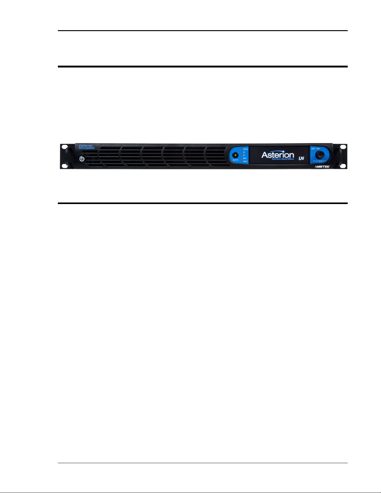
Figure 1-1. Asterion Series Front View, 1U Models (With Rackmount Brackets) ................................................ 13
Figure 2-1. iX2TM Constant-Power: Output Current Versus Voltage, AST 751/AST 1501 ................................... 18
Figure 2-2. iX2TM Constant-Power: Output Current Versus Voltage, AST 501 .................................................... 18
Figure 3-1. Rackmounting, 1U Models ................................................................................................................ 34
Figure 3-2. Rear Panel Protective Cover Installation........................................................................................... 35
Figure 3-3. Installation Drawing, Enhanced 1U Models....................................................................................... 36
Figure 3-4. Installation Drawing, ATE 1U Models ................................................................................................ 37
Figure 3-5. Rear Panel View, 1U Models, (with GPIB and LKM/LKS options) .................................................... 38
Figure 3-6. AC Input Connector and Safety-Ground ........................................................................................... 39
Figure 3-7. AC/DC Output Connector and Functional-Ground ............................................................................ 41
Figure 3-8. External Input/Output Control Connector .......................................................................................... 45
Figure 3-9. External Interface Signal Connector ................................................................................................. 48
Figure 3-10. External Command Monitor and Trigger Output Connectors .......................................................... 49
Figure 3-11. External Clock/Lock Interface Connectors (Option) ........................................................................ 49
Figure 3-12. External Master/Auxiliary System Interface Connectors ................................................................. 50
Figure 3-13. RS-232C Interface Connector ......................................................................................................... 51
Figure 3-14. USB Interface Connector ................................................................................................................ 52
Figure 3-15. LAN Interface 8P8C Modular Connector ......................................................................................... 53
Figure 3-16. Connections for 3-Phase Master/Auxiliary Group, 1U Models ........................................................ 55
Figure 3-17. Connections for 1-Phase Parallel Group, 1U Models ...................................................................... 56
Figure 4-1. Front Panel, Enhanced 1U Models ................................................................................................... 57
Figure 4-2. Front Panel, ATE 1U Models ............................................................................................................ 57
Figure 4-3. Functional Test Setup ....................................................................................................................... 62
Figure 4-4. iX2TM Constant-Power Output Characteristic ................................................................ .................... 63
Figure 4-5. HOME Screen ................................................................................................................................... 64
Figure 4-6. DASHBOARD Screen Menu with Voltage Selection-Field Active ..................................................... 64
Figure 4-7. Touch-Screen Numeric Keypad ........................................................................................................ 64
Figure 4-8. Rotary Encoder ................................................................................................................................. 65
Figure 4-9. Output Program Menu Selection-Fields with Voltage Highlighted ..................................................... 66
Figure 4-10. Highlighted Voltage Selection-Field with Value Window ................................................................. 66
Figure 4-11. Power-On Screens .......................................................................................................................... 70
Figure 4-12. HOME Screen Pages ...................................................................................................................... 71
Figure 4-13. DASHBORD Screen Top-Level Menu ............................................................................................ 73
Figure 4-14. Real-Time, Immediate Output Parameter Adjustment .................................................................... 74
Figure 4-15. Default Screen ................................................................................................................................ 74
Figure 4-16. OUTPUT PROGRAM Screen Top-Level Menu-1/2 ........................................................................ 75
Figure 4-17. MEASUREMENTS Screen Top-Level Menu-1/2/3 ......................................................................... 80
Figure 4-18. HARMONICS Menu ........................................................................................................................ 83
Figure 4-19. HARMONICS Menu, Table View .................................................................................................... 85
Figure 4-20. HARMONICS Menu, Bar Graph View ............................................................................................. 85
Figure 4-21. TRACE CAPTURE Screen ............................................................................................................. 86
Figure 4-22. TRACE Screen, Plus-Magnifier and Zoom Cursors ........................................................................ 86
Figure 4-23. TRACE Screen, Zoom View ............................................................................................................ 87
Figure 4-24. TRANSIENTS Screen Top-Level Menu .......................................................................................... 87
Figure 4-25. SETTINGS Menu ............................................................................................................................ 88
Figure 4-26. SETTINGS Screen, TRIGGER Sub-Menu ...................................................................................... 89
Figure 4-27. VIEW Menu, With Empty Buffer ...................................................................................................... 90
Figure 4-28. VIEW Menu, With Transient List Entry ............................................................................................ 90
Figure 4-29. VIEW Menu, ADD Sub-Menu .......................................................................................................... 90
Figure 4-30. VIEW Menu, VOLTAGE DROP Sub-Menu ..................................................................................... 93
Figure 4-31. VIEW Menu, VOLTAGE SWEEP/STEP Sub-Menu ........................................................................ 94
Figure 4-32. VIEW Menu, VOLTAGE SURGE/SAG Sub-Menu .......................................................................... 95
Figure 4-33. VIEW Menu, FREQUENCY SWEEP/STEP Sub-Menu ................................................................... 96
Figure 4-34. VIEW Menu, FREQUENCY SURGE/SAG Sub-Menu ..................................................................... 97
Figure 4-35. VIEW Menu, VOLT/FREQ SWEEP/STEP Sub-Menu ..................................................................... 98
Figure 4-36. VIEW Menu, VOLT/FREQ SURGE/SAG Sub-Menu ....................................................................... 99
Figure 4-37. VIEW Menu, DELAY Sub-Menu .................................................................................................... 100
Figure 4-38. RUN Menu .................................................................................................................................... 101
Figure 4-39. CONFIGURATION Screen Top-Level Menu ................................................................................. 102
Figure 4-40. CONFIGURATION Menu, PROFILES Sub-Menu ......................................................................... 103
Page 10

Asterion Series User Manual – 1U Models California Instruments
10 M330000-01, REV-G
Figure 4-41. PROFILES Menu, NAME Sub-Menu ............................................................................................ 103
Figure 4-42. CONFIGURATION Menu, PONS Menu-1/2 ................................................................................. 104
Figure 4-43. CONTROL INTERFACE Screen................................................................................................... 109
Figure 4-44. CONTROL INTERFACE Menu, ANALOG Sub-Menu ................................................................... 110
Figure 4-45. CONTROL INTERFACE Menu, GPIB Sub-Menu ......................................................................... 110
Figure 4-46. CONTROL INTERFACE Menu, RS232 Sub-Menu ....................................................................... 110
Figure 4-47. CONTROL INTERFACE, LAN Menu ............................................................................................ 112
Figure 4-48. CONTROL INTERFACE, LAN CONFIGURE Sub-Menu .............................................................. 112
Figure 4-49. CONTROL INTERFACE REMOTE INHIBIT Menu ....................................................................... 114
Figure 4-50. APPLICATIONS Screen, Output Impedance Example ................................................................. 115
Figure 4-51. SYSTEM SETTINGS Screen ........................................................................................................ 115
Figure 4-52. SYSTEM SETTINGS Menu, LCD Menu ....................................................................................... 116
Figure 5-1. HARMONICS Screen, Waveform Information ................................................................................ 120
Figure 6-1. HARMONICS Menu ........................................................................................................................ 124
Figure 6-2. FFT data in Tabular Format ............................................................................................................ 125
Figure 6-3. FFT data in Bar Graph Format ....................................................................................................... 125
Figure 6-4. Waveform Display on TRACE Screen ............................................................................................ 126
Figure 6-5. TRACE Screen, Zoom View Cursors .............................................................................................. 126
Figure 6-6. TRACE Screen, Expanded Zoom View .......................................................................................... 127
Figure 6-7. HARMONICS Menu, Triggering ...................................................................................................... 128
Figure 6-8. Post-Trigger (Positive Delay) .......................................................................................................... 129
Figure 6-9. Pre-Trigger (Negative Delay ........................................................................................................... 129
Figure 7-1. Output Transient Modes ................................................................................................................. 132
Figure 7-2. Pulse Transients ............................................................................................................................. 133
Figure 7-3. List Transients ................................................................................................................................ 133
Figure 7-4. Switching Waveforms in a Transient List Transient Execution ....................................................... 135
Figure 7-5. RUN Menu: Start and Abort Fields ................................................................................................. 135
Figure 7-6. CONFIGURATION Menu, PROFILES Selection ............................................................................ 136
Figure 8-1. AUX Generator PWA Potentiometer, R9 ........................................................................................ 149
Page 11

Asterion Series User Manual – 1U Models California Instruments
M330000-01, REV-G 11
List of Tables
Table 3-1. AC Input Connector Pinout and Safety-Ground ................................................................................. 40
Table 3-2. AC Input Connector Type ................................................................................................................... 40
Table 3-3. AC/DC Output Connector Pinout and Functional-Ground .................................................................. 41
Table 3-4. AC/DC Output Connector Type and Functional-Ground .................................................................... 41
Table 3-5. Minimum Wire Size ............................................................................................................................ 43
Table 3-6. Wire Resistance and Voltage Drop, 20°C .......................................................................................... 44
Table 3-7. External Input/Output Control Connector Type .................................................................................. 45
Table 3-8. External Input/Output Control Functions ............................................................................................ 46
Table 3-9. External Input/Output Control Connector Pinout ................................................................................ 47
Table 3-10. External Interface Signal Connector Type ........................................................................................ 48
Table 3-11. External Command Monitor and Trigger Output Characteristics ...................................................... 49
Table 3-12. External Clock/Lock Interface Characteristics (Option) .................................................................... 50
Table 3-13. External Master/Auxiliary System Interface Connector Type ........................................................... 50
Table 3-14. External Master/Auxiliary System Interface Characteristics ............................................................. 51
Table 3-15. RS-232C Interface Connector Type ................................................................................................. 51
Table 3-16. RS-232C Interface Connector Pinout ............................................................................................... 51
Table 3-17. USB Interface Connector Pinout ...................................................................................................... 52
Table 3-18. LAN Interface 8P8C Modular Connector Pinout ............................................................................... 53
Table 4-1. Front Panel Controls and Indicators, Enhanced 1U Models ............................................................... 58
Table 4-2. Front Panel Controls and Indicators, ATE 1U Models ........................................................................ 59
Table 4-3. HOME Screen-1 Menu Structure ....................................................................................................... 67
Table 4-4. Home Screen-2 Menu Structure ......................................................................................................... 68
Table 4-5. HOME Screen-2 Menu Structure (continued) ..................................................................................... 69
Table 4-6. HOME Screen-3 Menu Structure ....................................................................................................... 70
Table 4-7. HOME Screen-1, Screen-2, Screen-3 Menu Content ........................................................................ 72
Table 6-1. MEASUREMENTS Screen Parameters ........................................................................................... 123
Table 6-2. MEASUREMENTS Parameter Value Derivation .............................................................................. 124
Table 8-1. Calibration Equipment ...................................................................................................................... 137
Table 8-2. Load Values for Output AC Current Alignment ................................................................................. 145
Table 8-3. Load Values for Output DC Current Alignment ................................................................................ 145
Table 10-1. Error and Status Messages ................................ ................................ ............................................ 157
Page 12

Asterion Series User Manual – 1U Models California Instruments
Page 13
Asterion Series User Manual – 1U Models California Instruments
M330000-01, REV-G 13
1. Introduction
This instruction manual contains information on the installation, operation, and calibration of the
Asterion Series power source models with 1-phase output in 1U chassis. The Asterion Series is the
latest generation of switched-mode power sources that provide precise output having high accuracy, low
distortion, and fast dynamic response. With extensive programmability and user interface, it offers a rich
feature set and functionality: AC and DC output capability, wide output frequency range, arbitrary and
harmonic waveform generation, sequencing of transient lists, digital power analyzer measurements,
real-time waveform display, and the capability to be configured in systems comprised of multi-phase and
parallel groups.
Figure 1-1. Asterion Series Front View, 1U Models (With Rackmount Brackets)
1.1 General Description
The Asterion Series power sources are available in 1U chassis at power levels of 500 VA, 750 VA, and
1500 VA. Two AC output voltage ranges are provided, 0-200 VAC/0-400 VAC, with a frequency range of
16 Hz-1200 Hz (with up to 5000 Hz as an option), two DC output ranges, 0-250 VDC/0-500 VDC, and a
combined AC+DC mode. A wide range of AC and DC loads could be powered, including reactive loads
(inductive and capacitive) running at full rated apparent power, and non-linear loads drawing current with
high crest factor, up to 7:1.
The output has an iX2TM constant-power characteristic that provides greater output current at reduced
output voltage: up to 2X at 50% of full-scale voltage. Wide-range AC input is accepted, including
100/115/230/240 VAC, 1-phase/3-phase, and 50/60/400 Hz input frequency. Power factor correction of
the AC input exhibits a sinusoidal current waveform with low input current harmonics. Up to six 1U units
could be connected in parallel or in multi-phase groups, with outputs of up to 9 kVA.
Multiple remote digital communications interfaces are available: standard LAN (Ethernet), USB, and
RS-232C, or the optional IEEE-488 (GPIB) interface. The Asterion Virtual Panels program provides a
convenient graphical user interface, and the SCPI command set allows access to the full
programmability and functionality. Extensive remote analog and discrete digital control interfaces are
also provided for specialized control applications. The front panel display has capability for control,
programming, and measurements of the power source, and features a menu-based interface with
touch-screen data/command entry.
Waveform generation includes standard sine wave and square wave, and extensive programmability to
produce complex waveforms based on harmonics or arbitrary parameter value/time relations. A transient
generator could combine sequences of voltage, frequency, and wave shape to simulate real-world AC or
DC disturbances, and automate a complex profile of power stimulus to the unit under test.
The power analyzer utilizes DSP-based digitization of output parameters to implement measurement
functions spanning single parameter values (voltage/current/frequency), power characteristics
(true/apparent power, crest factor, power factor), and advanced computation using fast Fourier transform
(FFT) derivation of the harmonics and distortion contained in the voltage and current waveforms.
Real-time display of output waveforms is possible through the front panel display or the
Asterion Virtual Panels.
Page 14
Asterion Series User Manual – 1U Models California Instruments
14 M330000-01, REV-G
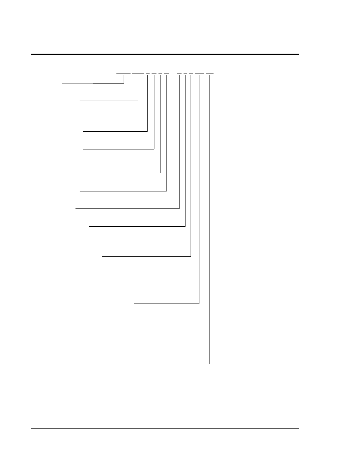
1.2 Asterion Series Models
AST 150 1 A 1 B – E 0 0 0A 00
Series
Asterion
Output Power
050 = 500 W 225 = 2250 W
075 = 750 W 300 = 3000 W
150 = 1500 W 450 = 4500 W
Output Phases
1 = 1-phase; 2 = 2-phase; 3 = 3-phase
Product Family
A = AC, Standard
B = AC, Low Aubile Noise
Number of Chassis
Number of chassis = 1, 2, 3, etc.
Input Voltage
B = universal, 100-240 VAC
Front Panel
E = Enhanced; A = ATE
Interface Options
0 = none
1 = GPIB
2 = GPIB - MC
Avionics Test Options
0 = none 6 = B787 - MC
1 = B787 7 = AMD - MC
2 = AMD 8 = B787 & AMD - MC
3 = B787 & AMD 9 = AVSTD - MC
4 = AVSTD A = AVALL - MC
5 = AVALL
Frequency and Clock/Lock Options
0A = None 2C = HF & LKS
1A = HF 2D = LF & LKM
1B = LF 2E = LF & LKS
1C = FC 2F = FC & LKM
1D = LKM 2G = FC & LKS
1E = LKS 3A = HF & FC & LKM
2A = HF & FC 3B = HF & FC & LKS
2B = HF & LKM
Other Options
0A = None 1G = 1399 - MC 2G = 411 - 1399 3B = MB - 411 - 413 - MC
1A = 411 2A = 411 - 413 2H = 413 - 1399 3C = MB - 411 - 1399
1B = 413 2B = MB - 411 2I = MB - 1399 3D = MB - 41 - 1399 - MC
1C = MB 2C = MB - 413 2J = 411 - 1399 - MC 3E = MB - 413 - 1399
1D = 411 - MC 2D = 411 - 413 - MC 2K = 413 - 1399 - MC 3F = MB - 413 - 1399 - MC
1E = 413 - MC 2E = MB - 411 - MC 2L = MB - 1399 - MC 4A = MB - 411 - 413 - 1399
1F = 1399 2F = MB - 413 – MC 3A = MB - 411 - 413 4B = MB - 411 - 413 - 1399 - MC
Page 15
Asterion Series User Manual – 1U Models California Instruments
M330000-01, REV-G 15
2. Specifications
Unless otherwise noted, the specifications are valid under the following conditions:
1. Ambient temperature of 25 5C, after a 30-minute warm-up, and at fixed AC input line and load;
2. Individual unit and individual output phase, with sine wave output, and into a resistive load;
3. For system configurations, specifications are for phase output, line-to-neutral; phase angle
specifications are valid under balanced resistive load conditions.
2.1 Electrical Characteristics
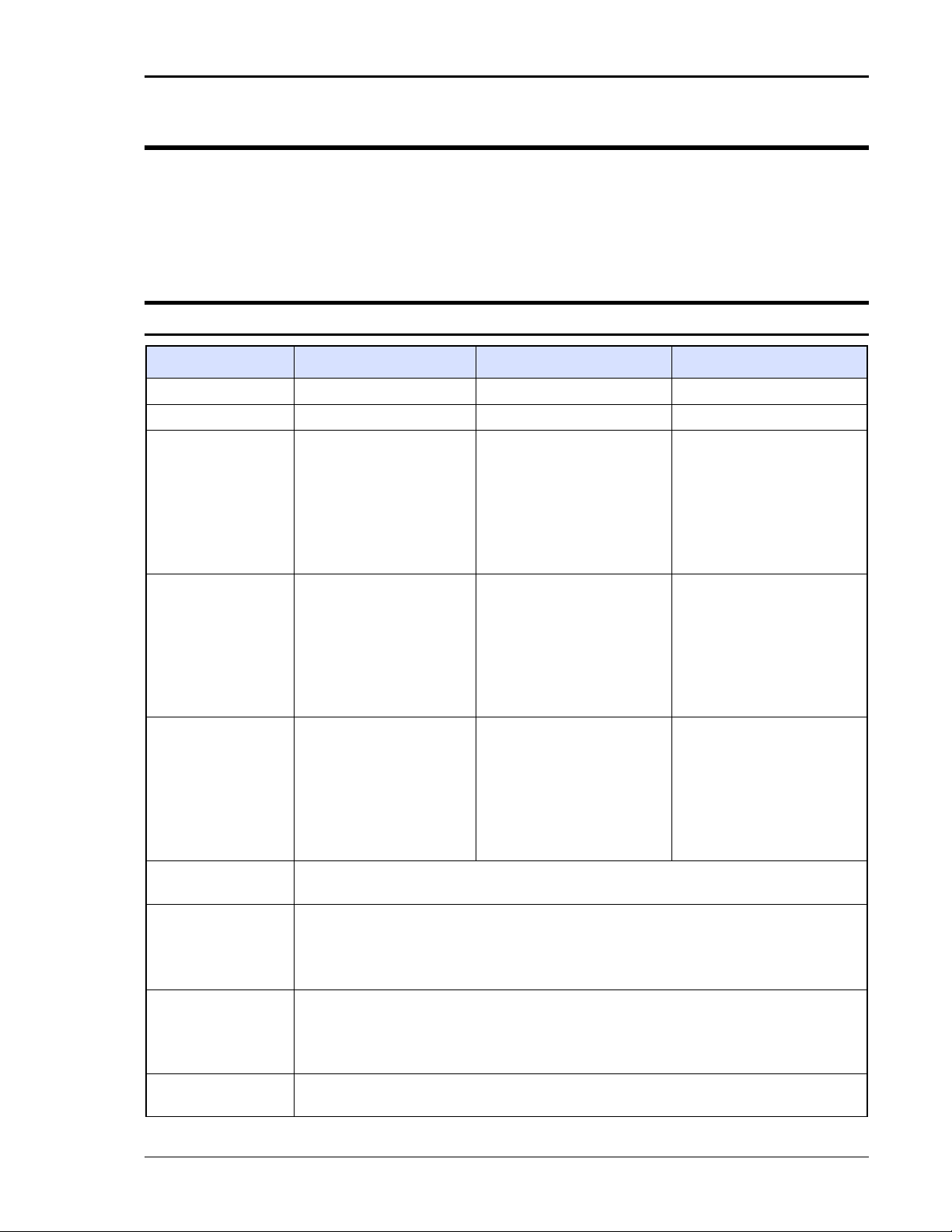
2.1.1 AC/DC Output Specifications
Model
AST 501
AST 751
AST 1501
Enclosure
1U
1U
1U
Output Phase
1-Phase
1-Phase
1-Phase
Output Power
500 VA/ 500 W
750 VA/ 750 W;
Low Audible Noise Models:
derate power above 30 °C at
12 W/°C.
1500 VA/ 1500 W;
derate output power with AC
input line-to-line voltage:
from 1,500 W at 103.5 VAC
to 1,300W at 90 VAC;
Low Audible Noise Models:
derate power above 30 °C at
25 W/°C.
AC and AC+DC
Output Current,
Full-Scale
Low-Range:
2.5 A(RMS) at 200 VAC;
iX2TM, 5.0 A(RMS)
maximum at 100 VAC.
High-Range:
1.25 A(RMS) at 400 VAC;
iX2TM, 2.5 A(RMS)
maximum at 200 VAC.
Low-Range:
3.75 A(RMS) at 200 VAC;
iX2TM, 7.5 A(RMS) maximum
at 100 VAC.
High-Range:
1.875 A(RMS) at 400 VAC;
iX2TM, 3.75 A(RMS)
maximum at 200 VAC.
Low-Range:
7.5 A(RMS) at 200 VAC;
iX2TM, 15 A(RMS) maximum
at 100 VAC.
High-Range:
3.75 A(RMS) at 400 VAC;
iX2TM, 7.5 A(RMS)
maximum at 200 VAC.
DC Output Current,
Full-Scale
Low-Range:
2.0 ADC at 250 VDC;
iX2TM, 4.0 ADC maximum
at 125 VDC.
High-Range:
1.0 ADC at 500 VDC;
iX2TM, 2.0 ADC maximum
at 250 VDC.
Low-Range:
3.0 ADC at 250 VDC;
iX2TM, 6.0 ADC maximum at
125 VDC.
High-Range:
1.5 ADC at 500 VDC;
iX2TM, 3.0 ADC maximum at
250 VDC.
Low-Range:
6.0 ADC at 250 VDC;
iX2TM, 12 ADC maximum at
125 VDC.
High-Range:
3.0 ADC at 500 VDC;
iX2TM, 6.0 ADC maximum at
250 VDC.
Output Current,
Maximum
iX2TM, 200% of the full-scale RMS current at ≤50% of full-scale voltage. Refer to Figure
2-1 and Figure 2-2 for graphs of current rating as a function of output frequency.
iX2TM
Constant-Power
Mode
Constant-Power output capability in each output voltage range with full rated output
power from 50% of full-scale output voltage to 100% of full-scale; the output current
increases to 200% of rated current at 50% full-scale output voltage from 100% rated
current at 100% of full-scale voltage. Refer to Figure 2-1 and Figure 2-2 for graphs of
current rating as a function of output frequency.
AC and AC+DC
Output Voltage,
Full-Scale
Low-Range: 0 to 200 V(RMS); High-Range: 0 to 400 V(RMS)
HF Option: derate full-scale output voltage from 4 kHz to 5 kHz, as follows,
Low Range, Vout ≤ 800 V-kHz / Fout, with Fout in kHz;
High Range, Vout ≤ 1600 V-kHz / Fout, with Fout in kHz.
DC Output Voltage,
Full-Scale
Low-Range: 0 to 250 VDC; High-Range: 0 to 500 VDC
Page 16

Asterion Series User Manual – 1U Models California Instruments
16 M330000-01, REV-G
Model
AST 501
AST 751
AST 1501
DC Offset Voltage,
typical
±20 mVDC, ≥40 Hz
Output Float
Voltage
566 V(PK), maximum from either output terminal to chassis
Voltage
Programming
Accuracy
±(0.1% of actual + 0.2% of full-scale) for DC, and AC 16 Hz to 1.2 kHz; >1.2 kHz, add
±0.2% of full-scale/kHz; add ±0.1% of full scale for AC+DC mode. Valid from 5% to 100%
of full-scale; with sense leads connected.
Voltage Resolution
≤0.02 V, AC, DC, and AC+DC mode
Voltage Temp.
Coefficient, typical
≤100 ppm/°C of full-scale
Voltage Stability,
Typical
±0.1% of full-scale over 8 hours; with constant line, load, and temperature;
with sense leads connected
Voltage Distortion
0.25% maximum, 16 Hz to 100 Hz; 0.5% maximum, >100Hz to 500 Hz; and
1% maximum, >500 Hz to 1.2 kHz, plus 0.5%/kHz to 5 kHz; at full linear load or no load;
valid for output voltage >5% of full-scale at full load, and >15% of full-scale at no load.
Voltage Slew Rate,
typical
≥10 V/µs, with full-scale programmed voltage step
Current
Programming
Range
Programmable from zero to 200% of full-scale rating in each output range. Refer to
Figure 2-1 and Figure 2-2 for graphs of current rating as a function of output frequency.
Current
Programming
Accuracy
±(0.3% of actual + 0.5% of maximum) for DC, and AC 16 Hz to 1.2 kHz; add ±0.1% of
maximum for AC+DC mode. Valid from 5% to 100% of maximum.
HF option: for High-Range, add 1.2% of maximum/kHz above 1.2 kHz; for Low-Range,
add 0.1% of maximum/kHz above 1.2 kHz. Valid from 20% to 100% of maximum.
For multi-chassis configurations, multiply the accuracy by √1.5𝑛, where 𝑛 is number of
chassis.
Line Regulation
±0.015% of full-scale voltage, for a ±10% input line change; DC, or 40 Hz to 5 kHz.
Load Regulation
±0.025% of full-scale voltage, for 100% of rated resistive load change; DC, or 40 Hz to
1.2 kHz; above 1.2 kHz, add ±0.015% of full-scale/kHz.
V/I Programming
Overrange, Typical
1% of full-scale
Noise Level, typical
AC output: 450 mV(RMS), low-range; 750 mV(RMS), high-range;
at ≥40 Hz output frequency; bandwidth, 20 kHz to 1 MHz;
DC output: 400 mV(RMS), low-range; 700 mV(RMS), high-range;
bandwidth, 20 Hz to 1 MHz.
Remote Sense
5 V(RMS), maximum total output lead drop
Crest Factor
AST 751, AST 1501: 5:1 of full-scale current per output range (ratio of peak to RMS);
AST 501: 7:1 of full-scale current per output range (ratio of peak to RMS).
Output Power
Factor
0, lagging to 0, leading
Frequency,
Range
Standard models: DC, and 16 Hz to 1.2 kHz;
LF option: DC, and 16 Hz to 550 Hz; HF option: DC, and 16 Hz to 5 kHz.
Frequency
Accuracy,
(FC option)
Standard models: ±(0.01% of actual + frequency resolution/2);
FC option: ±0.25%.
Page 17
Asterion Series User Manual – 1U Models California Instruments
M330000-01, REV-G 17
Model
AST 501
AST 751
AST 1501
Frequency
Resolution
Standard: 0.01 Hz resolution, 16-81.91 Hz; 0.1 Hz resolution, 82-819.1 Hz;
1 Hz resolution, 820-5000 Hz;
with LKM/LKS option: 1 Hz resolution, 16-5000 Hz.
Frequency Temp.
Coefficient, typical
10 ppm/ºC of full-scale range
Phase
Programming
Range
0.0º to 360.0º, relative to external synchronization signal; in multi-phase group, Auxiliary
unit output voltage is relative to the Master unit output voltage, with the Master unit
voltage as reference 0°.
Phase Accuracy
±1º, 16 Hz to 100 Hz; ±2º >100 Hz to 1.2 kHz, plus ±1º/kHz above 1.2 kHz
Phase
Programming
Resolution
±0.4º
Page 18
Asterion Series User Manual – 1U Models California Instruments
18 M330000-01, REV-G
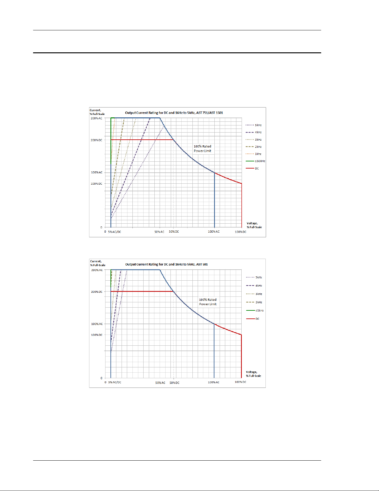
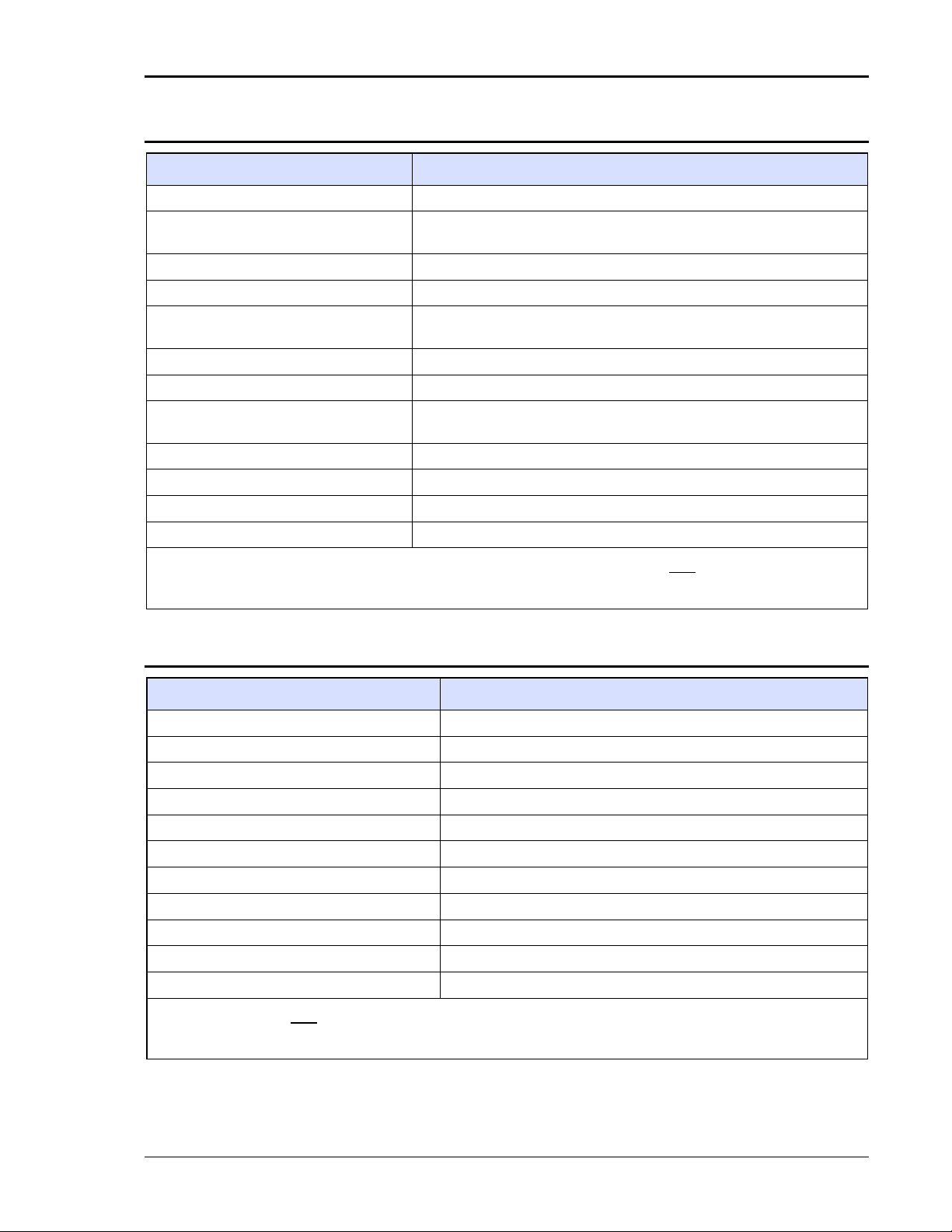
2.1.3 iX2
TM
Constant-Power Mode Output Characteristic
The iX2TM Constant-Power mode has an output characteristic where full rated output power is available
from 50% of full-scale output voltage to 100% of full-scale output voltage, as depicted in the graphs of
Figure 2-1 and Figure 2-2. The output current versus output voltage follows a constant-power relation
where the output current would be 200% of the full-scale value when the output voltage is 50% of
full-scale. The current ratings are also a function of output frequency, as shown in Figure 2-1 above
500 Hz for the AST 751 and AST 1501 models, and in Figure 2-2 above 1 kHz for the AST 501 models.
Figure 2-1. iX2TM Constant-Power: Output Current Versus Voltage, AST 751/AST 1501
Figure 2-2. iX2TM Constant-Power: Output Current Versus Voltage, AST 501
Page 19

Asterion Series User Manual – 1U Models California Instruments
M330000-01, REV-G 19
2.1.4 AC Input Specifications
Model
AST 501
AST 751
AST 1501
Enclosure
1U
1U
1U
Input Voltage,
Nominal Rating
100VAC-120VAC
low-input range, and
200-240 VAC high-input
range;
1-Phase and 3-Phase,
line-neutral or line-line.
100VAC-120VAC
low-input range, and
200-240 VAC high-input
range;
1-Phase and 3-Phase,
line-neutral or line-line.
100VAC-120VAC low-input
range, and
200-240 VAC high-input
range;
1-Phase and 3-Phase,
line-neutral or line-line.
Input Voltage,
Operating Range
90-132 VAC low-input
range, and
180VAC-264VAC
high-input range.
.
90-132 VAC low-input
range, and
180VAC-264VAC
high-input range.
90-132 VAC low-input
range, and
180VAC-264VAC
high-input range;
derate output power for
operation with 1-Phase AC
input and line-to-line
voltage: from 1,500 W at
103.5 VAC to 1,300W at
90 VAC.
Input Frequency,
Nominal Rating
50 Hz, 60 Hz, 400 Hz
50 Hz, 60 Hz, 400 Hz
50 Hz, 60 Hz, 400 Hz
Input Frequency Range
47-440 Hz
47-440 Hz
47-440 Hz
Input Current,
maximum with
1-Phase input
7.6 A(RMS) at 90 VAC
11 A(RMS) at 90 VAC
20 A(RMS) at
90 VAC to 103.5 VAC
Input Current,
maximum with
3-Phase input
4.4 A(RMS) at 90 VAC,
line-to line
6.5 A(RMS) at 90 VAC,
line-to line
13 A(RMS) at 90 VAC,
line-to line
Efficiency1, typical
AST 1501: 75%;
AST 751: 72%;
AST 501: 69%.
AST 1501: 75%;
AST 751: 72%;
AST 501: 69%.
AST 1501: 75%;
AST 751: 72%;
AST 501: 69%.
Power Factor2, typical
0.98; active PFC
0.98; active PFC
0.98; active PFC
Hold-Up Time
3
, typical
≥10 ms
≥10 ms
≥10 ms
Inrush Current, typical
30 A (PK) at 264 VAC
30 A (PK) at 264 VAC
30 A (PK) at 264 VAC
1-PH Input
2 wire + ground; 264 VAC, maximum
3-PH Input
3 wire + ground; 264 VAC, maximum line-to-line
Isolation Voltage
2200 VAC, input to output; 1350 VAC, input to chassis
1
At full load and DC or 16 Hz to 1.2 kHz output frequency, with AC input voltage of 115 V(RMS) or 230 V(RMS),
and 50/60 Hz input frequency
2
At full load, with 1-phase AC input voltage of 115 V(RMS) or 230 V(RMS), and 50/60 Hz input frequency
3
At full load and with AC input voltage of 115 V(RMS) or 230 V(RMS)
Page 20

Asterion Series User Manual – 1U Models California Instruments
20 M330000-01, REV-G
2.1.5 AC Output Measurements
Parameter
Specification
1
Voltage Range, Full-Scale
AC and AC+DC output: 0-500 V(RMS)
Voltage Accuracy
±(0.1% of actual + 0.2% of full-scale) for AC 16 Hz to 1.2 kHz; >1.2 kHz,
add ±0.2% of full-scale/kHz; add ±0.1% of full-scale for AC+DC mode. Valid
from 5% to 100% of full-scale; with sense leads connected.
Voltage Resolution
20 mV
Current Range, Maximum
AST 501, AST 751: 7.5 A(RMS); AST 1501: 15 A(RMS).
Current Accuracy
±(0.3% of actual + 0.5% of maximum) for AC, 16 Hz to 1.2 kHz; add ±0.1%
of full-scale for AC+DC mode. Valid from 5% to 100% of maximum.
HF Option: High-Range, add 1.2% of maximum/kHz; Low-Range, add 0.1%
of maximum/kHz. Valid from 20% to 100% of maximum.
Current Resolution
2 mA
Peak Current Range, Maximum
AST 501, AST 751: ± 0-18.75 A(PK); AST 1501: ± 0-37.5 A(PK).
Peak Current Accuracy
±(0.5% of actual 0.7% of maximum) for AC 16 Hz to 1.2 kHz; add ±0.1% of
maximum for AC+DC mode. Valid from 5% to 100% of maximum.
HF Option: High-Range, add 1.2% of maximum/kHz above 1.2 kHz;
Low-Range, add 0.1% of maximum/kHz above 1.2 kHz. Valid from 20% to
100% of maximum.
Peak Current Resolution
5 mA
Frequency Range
16 Hz to 5.0 kHz
Frequency Accuracy
±(0.01% of actual + frequency resolution/2)
Frequency Resolution
0.01 Hz: 16-81.91 Hz; 0.1 Hz: 82.0-819.1 Hz; 1 Hz: 820-5.0 kHz
Phase Range
0-360°
Phase Accuracy
±1°, 16 Hz to 100 Hz; ±2°, >100 Hz to 1.2 kHz; ±5°, >1.2 kHz
Phase Resolution
0.1°, 16-100 Hz; 1°, >100 Hz to 5 kHz
Real Power Range, Full-Scale
Output power rating of model.
Real Power Accuracy
±(0.4% of actual + 0.7% of full-scale) for AC 16 Hz to 1.2 kHz; >1.2 kHz,
add ±0.4% of full-scale/kHz; add ±0.2% of full-scale for AC+DC mode.
Real Power Resolution
1 W
Apparent Power Range,
Full-Scale
Output power rating of model.
Apparent Power Accuracy
±(0.4% of actual + 0.7% of full-scale) for AC 16 Hz to 1.2 kHz; >1.2 kHz,
add ±0.4% of full-scale/kHz; add ±0.2% of full-scale for AC+DC mode.
Apparent Power Resolution
1 VA
Power Factor Range, Full-Scale
0-1
Power Factor Accuracy
±2% of full-scale
Power Factor Resolution
0.01
1
Accuracy specifications apply above 100 counts of resolution; for multi-chassis configurations, multiply the
output current and power by the number of chassis, and their accuracy specifications by √1.5𝑛, where 𝑛 is
number of chassis; power factor accuracy applies for PF > 0.5 and output apparent power > 50% of maximum
rating; frequency measurement specifications valid for output voltage >5% of full-scale in each range.
Page 21
Asterion Series User Manual – 1U Models California Instruments
M330000-01, REV-G 21
2.1.6 DC Output Measurements
Parameter
Specification1
Voltage Range, Full-Scale
±500 VDC
Voltage Accuracy
±(0.1% of actual + 0.2% of full-scale); valid from 5% to 100% of
full-scale; with sense leads connected.
Voltage Resolution
25 mV
Current Range, Maximum
AST 501, AST 751: 6 ADC; AST 1501: 12 ADC.
Current Accuracy
±(0.5% of actual + 0.5% of maximum); valid from 5% to 100% of
maximum.
Current Resolution
2 mA
Peak Current Range, maximum
AST 501, AST 751: ± 0-18.75 A(PK); AST 1501: ± 0-37.5 A(PK).
Peak Current Accuracy
±(0.5% of actual + 0.7% of maximum); valid from 5% to 100% of
maximum.
Peak Current Resolution
5 mA
Power Range, Full-Scale
Output power rating of model.
Power Accuracy
±(0.4% of actual + 0.7% of full-scale)
Power Resolution
1 W
1
Accuracy specifications apply above 100 counts of resolution; for multi-chassis configurations, multiply the output
current and power by the number of chassis, and their accuracy specifications by √1.5𝑛, where 𝑛 is number of
chassis.
2.1.7 Harmonics Measurements
Parameter
Specification1
Frequency, Fundamental
16-81.91 Hz, 82.0-819.1 Hz, 820-960 Hz
Fundamental Frequency Resolution
0.01 Hz: 16-81.91 Hz; 0.1 Hz: 82.0-819.1 Hz; 1 Hz: 820-960 Hz
Harmonic Frequency
32 Hz to 48 kHz; 2nd to 50th harmonic
Fundamental Voltage Accuracy
±(0.2% of actual + 0.3% of full-scale) for 16 Hz to 960 Hz.
Fundamental Voltage Resolution
20 mV
Harmonic Voltage Accuracy
±(0.2% of actual + 0.3% of full-scale + 0.3% of full-scale/kHz).
Harmonic Voltage Resolution
20 mV
Fundamental Current Accuracy
±(0.4% of actual + 0.6% of maximum) for 16 Hz to 960 Hz.
Fundamental Current Resolution
2 mA
Harmonic Current Accuracy
±(0.4% of actual + 0.6% of maximum + 0.4% of maximum/kHz).
Harmonic Current Resolution
2 mA
1
Accuracy specifications apply above 100 counts of resolution; for multi-chassis configurations, multiply the
current accuracy by √1.5𝑛, where 𝑛 is number of chassis. Voltage and current measurements are valid from 5%
to 100% of maximum in each range.
Page 22
Asterion Series User Manual – 1U Models California Instruments
22 M330000-01, REV-G
2.1.8 Protection Function Characteristics
Function
Characteristic
Output Overvoltage Protection (OVP)
Programmable to 115% of full-scale output voltage;
exceeding OVP threshold results in shutdown of output.
Output Current Limit Protection
User-selectable constant-current mode or current-limit mode, with
programmable current setpoint;
in constant-current mode, output current is regulated to setpoint;
in current limit mode, exceeding current-limit setpoint results in
shutdown of output;
current-limit delay: programmable from 100 ms to 10 s.
Output Short-Circuit Protection
Instantaneous and RMS current-limit
AC Input Overcurrent Protection
Internal fuses in each phase for fault isolation; not user replaceable
AC Input Undervoltage Protection
Automatic shutdown for insufficient AC input voltage
AC Input Transient Protection
Protection to withstand EN61326-1, Class-A surge levels
Overtemperature Protection (OTP)
Internal temperature monitors cause shutdown of output if
temperature thresholds are exceeded
2.2 Environmental Specifications
Parameter
Specification
Operating Temperature
0°C to 40°C (32° F to 104° F)
Storage Temperature
-40°C to 85°C ( -40°F to 185° F)
Altitude
2000 m (6,562 ft)
Relative Humidity
5-95 %, non-condensing
Vibration
MIL-PRF-28800F, Class 3; 5-500 Hz per Paragraph 4.5.5.3.1
Shock
MIL-PRF-28800F, Class 3; 30G half-sine with 11ms duration per
Paragraph 4.5.5.4.1
Transportation Integrity
ISTA Test Procedure 1A
Page 23
Asterion Series User Manual – 1U Models California Instruments
M330000-01, REV-G 23
2.3 Mechanical Specifications
Parameter
Specification
Dimensions
H, 1.75” (44.45 mm); W (front panel), 19.0” (483mm); D, 23.0” (584mm);
H, 1.75” (44.45 mm); W (chassis), 16.9” (483mm); D, 23.0” (584mm).
Unit Weight
AST 501/751: 19 lb / 8.6 kg;
AST 1501: 22 lb / 10 kg.
Shipping Weight
AST 501/751: 29 lb / 13.2kg;
AST 1501: 32 lb / 14.5 kg.
Chassis Material
Steel with plastic front panel
Chassis Finish
Galvanized Zinc, G90
Installation
Protective covers are provided for AC input and AC/DC output;
bench-top: removable feet for the chassis;
rackmount: per ANSI-EIA-310-D, with front panel mounting flange brackets and chassis
provisions for mounting rack slides; slides and flange brackets/handles options available.
Cooling
Force-air cooling; linear, variable fan speed control; air intake at front/sides and exhaust
at rear.
Acoustic Noise
Standard: 65 dBA, maximum; measured at 1 m with A-weighting;
Low Audible Noise: 59 dBA, maximum; measured at 1 m with A-weighting.
2.4 Regulatory Agency Compliance
Parameter
Specification
EMC
CE marked for EMC Directive 89/336/EEC per EN61326-1:2013, Class-A for
emissions and immunity as required for the EU CE Mark.
Safety
CSA NRTL certified for US and Canada to CAN/CSA-C22.2 No. 61010-1-12,
UL 61010-1 Third Edition. CE marked for LVD compliance 2006/95/EC to
EN 61010-1 Third Edition as required for the EU CE mark.
CE Mark LVD Categories
Installation Overvoltage Category: ΙΙ; Pollution Degree: 2; Class II equipment;
indoor use only.
RoHS
CE marked for compliance with EU Directive 2011/65/EU for Restriction of
Hazardous Substances in Electrical and Electronic Equipment.
Page 24

Asterion Series User Manual – 1U Models California Instruments
24 M330000-01, REV-G
2.5 Remote Control Analog/Digital Signal Characteristics
Function
Characteristics
External Analog
Programming of
Output Voltage
Waveform
Signal input for output voltage waveform programming by external analog reference;
AC or DC input signal: 0V to user-selectable maximum range value within ±2.5 V(PK) to
±10 V(PK), corresponding to maximum range of 1.77 V(RMS) to 7.07 V(RMS), for zero to
full-scale RMS output voltage; with AC waveform, from 16 Hz to 5 kHz (option dependent);
programming accuracy, ±2% of full-scale output;
input impedance, 40 kΩ, typical.
External Analog
Programming of
Output Voltage
Amplitude (RPV)
Signal input for output voltage amplitude programming; waveform is set by internal
controller reference;
DC input signal: 0V to user-selectable maximum range value within 2.5 VDC to10 VDC, for
zero to full-scale RMS of internally programmed output voltage waveform;
programming accuracy, ±2% of full-scale output;
input impedance, 40 kΩ, typical.
External Analog
Programming
Modulation of
Output Voltage
Signal input for output voltage modulation; waveform is set by internal controller reference;
AC or DC input signal with 0V to ±7.07 V(PK), 0-5 V(RMS) for 0-20% of full-scale output
voltage amplitude modulation;
programming accuracy, ±2% of full-scale output;
input impedance, 40 kΩ, typical.
Trigger Output
Signal output with dual function: user-selectable as either function trigger or list trigger;
function trigger provides a pulse for any programmable change in output voltage or
frequency; list trigger provides a pulse if programmed as part of list transients;
logic level, active-low pulse with duration of 500 µs, typical.
Output Voltage
Monitor Outputs
Signal output for monitoring the waveform of the command signal of the output amplifier;
0-5 V(RMS), typical, signal range for zero to full-scale output voltage.
Trigger Input
Signal input for external trigger for execution of programmed values or transient lists;
logic level, TTL-compatible.
Synchronization
Signal (SYNC)
Input
Signal input for external square wave to control the output frequency and phase, with
waveform generated by the internal reference;
logic level, TTL-compatible.
Remote Inhibit
Input
Signal input to turn the output off/on; logic level, TTL-compatible; user-selectable as
active-high or active-low.
Summary Fault
Switch Output
Switch output indicating that a Summary Fault (DFI) condition is present;
normally-closed, bidirectional AC/DC solid-state switch;
closed-circuit for fault or when unit is turned off (open-circuit for no fault present);
switch ratings: ±12V, maximum peak voltage; 0.1A, maximum current; 2.5Ω, maximum
closed resistance; 6µA, maximum open-circuit leakage current at 12V.
LKM (Option)
Signal outputs for Master Clock and Lock signals used in synchronizing two or more power
sources;
logic level, TTL-compatible.
LKS (Option)
Signal inputs for Auxiliary Clock and Lock signals used in synchronizing two or more power
sources;
logic level, TTL-compatible.
Page 25
Asterion Series User Manual – 1U Models California Instruments
M330000-01, REV-G 25
2.6 Remote Control Digital Interface Characteristics
Interface
Characteristic
LAN
Ethernet 10BASE-T and 100BASE-T over twisted-pair cables compliant with IEEE 802.3;
Connector: 8P8C modular jack.
USB
Serial interface compliant to USB 2.0;
Connector: Type-B receptacle.
RS-232C
Serial interface compliant to RS-232C;
Protocol: data bits, 7 with parity and 8 without parity; stop bits, 2; baud rate, 9600 to
115200; handshake, CTS and RTS;
Connector: Subminiature-D, 9-contact receptacle.
IEEE-488 (Option)
Parallel interface complies with IEEE-488.1, IEEE-488.2, and the SCPI command
specification;
command execution response time, 10 ms, typical;
connector: IEEE-488.1 compliant.
Firmware Upgrade
Firmware could be upgraded through the LAN (units built starting September 2018), USB,
or RS-232 interfaces.
Upgrade through IEEE-488 is not supported.
Page 26

Asterion Series User Manual – 1U Models California Instruments
26 M330000-01, REV-G
2.7 Operational Characteristics
Parameter
Characteristic
Parallel Operation
Multi-chassis configurations could be formed with up to six units paralleled in
1-phase or 3-phase groups, using one master unit and up to five units operating
as auxiliary units. Setup of the multi-chassis configuration is automatically
accomplished when the chassis are interconnected with the interface cables, and
require no user setup, except to wire the outputs.
Output Relays
Isolation and range relays are provided internally to automatically configure the
outputs, turn the output on/off, and disconnect the load from the output amplifier
when in the off state.
Non-Volatile Memory
16 complete instrument setups and transient lists, 100 events per list.
Transient Generator
Output could be controlled to produce transient events with 500 µs programming
resolution:
Voltage: drop, step, sag, surge, sweep;
Frequency: step, sag, surge, sweep;
Voltage and Frequency: step, sweep.
Reliability
MTBF: > 110,000 hr;
calculation method: Telecordia SR-332, Issue 3; method: Method I (Parts
Count), Case 2 (Temp 40°C, Stress 50%, Burn-in 4 hr); ambient temperature:
40°C; temperature variation: 10°C; environment: Ground, Fixed, Controlled; duty
cycle: 100%; stress factor: 50%; quality level: 1; upper confidence level: 90%
Calibration
Calibration interval is 1 year; calibration is firmware-based through the digital
interface or Asterion Virtual Panels.
Fault Identification
On-board diagnostics identify when an assembly has experienced a fault.
XLOAD,
Output Characteristic
User-selectable XLOAD mode operation provides revised regulation
characteristics for additional stability margins when driving large capacitive loads.
Automatic Level Control
(ALC)
User-selectable ALC operation enables a digitally implemented feedback control
loop to provide precise regulation of the RMS value of the output voltage.
Clock and Lock Mode
(LKM and LKS options)
Multi-phase configurations could be formed with up to six units using the Clock
and Lock signal interface. One unit acts as the Master and provides the reference
signals to the other Auxiliary units. Requires LKM and LKS options.
LF option
Low frequency option: output frequency range of 16 Hz to 550 Hz.
HF option
High frequency option: output frequency range of 16 Hz to 5 kHz.
FC option
Reduced frequency control option: ±0.25% accuracy of output frequency; deletes
external waveform programming signal.
LKM option
Clock and Lock interface option, Master unit.
LKS option
Clock and Lock interface option, Auxiliary unit.
MB option
Upgrades all chassis to Enhanced models in a multi-chassis configuration
Low Audible Noise, option
Reduced acoustic noise generated by cooling fans.
Page 27

Asterion Series User Manual – 1U Models California Instruments
M330000-01, REV-G 27
2.8 Front Panel Controls/Indicators
Model Type
Controls/Indicators
Enhanced
TFT color LCD display with menu-based control and touch-screen;
rotary encoder for menu navigation and parameter adjustment and entry, with
integrated selection switch;
POWER switch: turns unit on/off;
OUTPUT switch: turns output of the unit on/off;
OUTPUT LED: integrated into the OUTPUT switch; indicates that the output of the unit
has been turned on;
CC LED: indicates that the unit is in constant-current mode and the output current is
being regulated;
CV LED; indicates that the unit is in constant-voltage mode and the output voltage is
being regulated;
HI RNG LED: indicates that the high-voltage output range has been selected;
FAULT LED: indicates that an internal fault has been detected and the output has been
shut down;
REM LED: indicates that the unit is under control of the remote digital interface.
ATE
No front-panel display; only status indicators;
POWER switch: turns unit on/off;
UPDATE switch: enables boot-loader for firmware upgrade;
POWER LED: indicates that the POWER switch has turned the unit on;
OUTPUT LED: indicates that the output of the unit has been turned on;
CC LED: indicates that the unit is in constant-current mode and the output current is
being regulated;
CV LED; indicates that the unit is in constant-voltage mode and the output voltage is
being regulated;
HI RNG LED: indicates that the high-voltage output range has been selected;
FAULT LED: indicates that an internal fault has been detected and the output has been
shut down;
REM/LAN LED: indicates that the unit is under control of the remote digital interface,
and provides LXI status.
Page 28

Asterion Series User Manual – 1U Models California Instruments
28 M330000-01, REV-G
2.9 Rear Panel Connectors
Connector
Description
AC Input
1-Phase AC input: L1 and L2; 3-Phase AC input: L1, L2, and L3;
connector: compression terminals, Phoenix P/N 1703050.
Safety-Ground
M4-0.7 chassis stud
AC/DC Output
Line and Return (RTN) connections;
connector: compression terminals, Phoenix P/N 1720819.
AC/DC Output
Remote Sense
Line and Return (RTN) connections;
part of AC/DC output connector, compression terminals, Phoenix P/N 1720819.
Functional-Ground
M4-0.7 chassis stud
External Interface
Control signal interface to external chassis;
connector: high-density, 15-contact, female Subminiature-D.
External
Input/Output Control
Control analog/digital signal interface for user remote control;
safety isolation SELV-rated;
connector: high-density, 15-contact, female Subminiature-D.
Auxiliary Interface
Control signal interface on Auxiliary unit coming from Master unit (or previous Auxiliary
unit) for multi-chassis operation;
connector, high-density, 26-contact, female Subminiature-D.
Master Interface
Control signal interface on Master unit (or previous Auxiliary unit) going to Auxiliary unit
for multi-chassis operation;
connector: high-density, 26-contact, female Subminiature-D.
Clock and Lock
(LKM and LKS
options)
Signal control interfaces for synchronization of multiple units;
signal outputs on Master unit, and signal inputs on Auxiliary units;
safety isolation SELV-rated; connectors: individual BNC.
Command Monitor
Signal output for monitoring waveform of command signal to internal output amplifier;
safety isolation SELV-rated; connector: individual BNC.
Trigger Output
Signal output with dual function, either function trigger or list trigger;
safety isolation SELV-rated; connector: BNC.
LAN Interface
Ethernet 10BASE-T and 100BASE-T;
safety isolation SELV-rated, referenced to chassis; connector: 8P8C modular jack.
RS-232C Interface
Serial interface to RS-232C;
safety isolation SELV-rated, referenced to chassis; connector: Subminiature-D,
9-contact receptacle.
USB Interface
Serial interface to USB 2.0;
safety isolation SELV-rated, referenced to chassis; connector: Type-B.
IEEE-488 Interface
(Option)
Parallel interface to IEEE-488.1, IEEE-488.2;
safety isolation SELV-rated, referenced to chassis; connector: IEEE-488.1 compliant.
Page 29
Asterion Series User Manual – 1U Models California Instruments
M330000-01, REV-G 29
2.10 Firmware/Software Options
Option1
Description
B787, (MC)
Avionics Electrical Power Quality Test Software; Boeing 787B3-0147 A/B/C (B787).
AMD, (MC)
Avionics Electrical Power Quality Test Software; Airbus AMD24 C (A400M).
B787 & AMD, (MC)
Includes both B787 and AMD options.
AVSTD, (MC)
Avionics Electrical Power Quality Test Software Package;
includes 160 (RTCA/DO160 E/F/G), 704 (MIL-STD 704 A/B/C/D/E/F),
ABD (Airbus ADB100.1.8 D/E), A350 (Airbus ADB100.1.8.1 B/C).
AVALL, (MC)
Avionics Electrical Power Quality Test Software Package;
includes AVSTD, B787, AMD.
1399, (MC)
MIL-STD-1399-300B shipboard power test software
411, (MC)
IEC 61000-4-11 voltage dips and interruptions EMC test software.
413, (MC)
IEC 61000-4-13 harmonics and Inter-harmonics EMC test hardware and software.
411 & 413, (MC)
Includes both 411 and 413 options.
MC
Options are installed in all chassis of a multi-chassis (MC) configuration.
1
For Avionics options, reference the Avionics Software Manual (P/N 4994-971) for test details. All options require
the use of the Asterion Virtual Panels graphical user interface Windows application software. Refer to the
AMETEK Programmable Power website, www.powerandtest.com, to download latest version.
Page 30

Page 31

Asterion Series User Manual – 1U Models California Instruments
M330000-01, REV-G 31
3. Installation
3.1 Unpacking
Inspect the shipping carton for possible damage before unpacking the unit. Carefully unpack the
equipment. Save all packing materials until inspection is complete. Verify that all items listed on the
packing lists have been received. Visually inspect all exterior surfaces for dented or damaged exterior
surfaces, and broken connectors, display, or controls. External damage might be an indication of
internal damage.
If any damage is evident, immediately contact the carrier that delivered the unit and submit a damage
report. Failure to do so could invalidate future claims. Direct repair issues to AMETEK Customer Service
Department at 858-458-0223 (local) or 1-800-733-5427 (toll free in North America).
3.1.1 Contents of Shipment
Depending on the model, configuration, and options selected for your Asterion Series power source, the
ship kit may include additional parts and accessories.
Minimum items included in the ship kit (P/N 5330177-01R):
1. AMETEK CD-ROM (P/N CIC496) containing the Asterion Series User Manual
(P/N M330000-02), and the Asterion Series Programming Manual (P/N M330100-01); refer to
AMETEK Programmable Power website, www.powerandtest.com, to download latest version;
2. Output mating connector (P/N, 893-177-78);
3. Protective cover for AC input, with fastening nuts (cover P/N 9330182-01R;
M4 nuts P/N MN-M04K-07, quantity three);
4. Strain relief for AC input cable, with mounting nut (strain relief P/N 109-346-00;
nut P/N MN-12PT-NNY);
5. Protective cover for AC/DC output, with fastening nuts (cover P/N 9330178-01R;
M4 nuts P/N MN-M04K-07, quantity two);
6. Bench-top chassis feet (quantity, four), with fastening screws/washers (bumper
P/N 109-075-37; M3 screw P/N 075072, quantity four; washer P/N 075075, quantity four);
7. Rackmount flange bracket kit (P/N 5330241-01R, quantity two; includes four M4 mounting
screws P/N FM1001).
Note: If any of these parts are missing, contact AMETEK Customer Service Department at
858-458-0223 (local) or 1-800-733-5427 (toll free).
Optional accessories:
890-010-01: Auxiliary cable, 12” long; one cable is required per unit that is placed in parallel; up to
five additional units could be paralleled;
890-010-26: Auxiliary cable, 60” long; one cable is required per unit that is placed in parallel; up to
five additional units could be paralleled;
250562: Clock/Lock interface cables, 36” long; two cables are required for every pair of units in a
multi-phase group;
250561: Clock/Lock interface BNC T-adapter; two adapters are required for every pair of units in a
multi-phase group;
5330201-01R: Rackmount slide kit; includes two slides with rack adapter brackets and mounting
hardware.
Page 32

Asterion Series User Manual – 1U Models California Instruments
32 M330000-01, REV-G
3.2 Mechanical Installation
The Asterion Series power source is designed for rackmount and bench-top applications. It could be
used free standing on a bench top or rackmounted using optional mounting hardware. For bench-top
use, the ship kit contains the four bumper feet for installing to the bottom of the chassis using the
M3-0.5 x 8 mm Philips pan-head screws and 3 mm washers. Rackmounting requires installing the
optional flange brackets with handles to the side of the chassis: using M4-0.7 x 6 mm Philips flat-head
screws to mount the brackets to the chassis, and # 8-32 Philips flat-head screws to mount the handles to
the brackets.
The unit is forced-air cooled with internal fans drawing air in from the front and sides, and exhausting at
the rear. The front and rear of the unit must be kept clear of obstruction and clearance must be
maintained to allow unimpeded airflow. The same consideration given to the side grilles will minimize
internal temperature rise. Special consideration must be made to overall air flow characteristics, and the
resultant internal heat rise, when a source is installed inside enclosed cabinets to avoid excessive
heating and over-temperature problems. The temperature of the ambient air at the air intake should not
exceed 40°C.
WARNING!
This unit is intended for installation in a protected environment. Exposure to conductive
contaminants or corrosive compounds/gases that could be ingested into the chassis
could result in internal damage. Install the power source in a temperature and humidity
controlled indoor area.
CAUTION!
The power source should be provided with proper ventilation. The front and rear of the
unit must be free of obstructions. To ensure proper airflow, a minimum 2" clearance from
the rear air outlet is required.
CAUTION!
No user serviceable parts are inside; service is only to be performed by qualified
personnel.
Page 33

Asterion Series User Manual – 1U Models California Instruments
M330000-01, REV-G 33
3.2.1 Rackmounting
The Asterion Series power source is designed for mounting in a standard 19-inch equipment rack that is
compliant to ANSI/EIA-310-D. If other instrumentation is mounted in the rack adjacent to the unit, there
is no need for additional clearance above or below the source. It should be supported in the rack using
appropriate L-brackets or rackmount slides. Refer to Figure 3-1 for typical rackmount installation.
.
Recommended rackmount kits are as follows:
Rackmount Slide Kit (Option): AMETEK part number 5330201-01R
Rackmount Flange Bracket Kit (Option): AMETEK part number 5330241-01R
Install the rackmount kit as follows:
1. Install the slide sections, , on both sides of the power supply chassis with screws, ,
(three on each side).
2. Install the brackets, , to the stationary slide sections, , with screws, , and nuts, ,
(four on each side).
3. Adjust the location of the mounting brackets as required for the particular type of rack cabinet
vertical rails utilized.
4. Mount the stationary slide sections, , (with brackets already installed) into the cabinet
using appropriate hardware (e.g. the screws and nuts supplied, and ,
or user-supplied bar-nuts, cage-nuts, clip-nuts), while ensuring that they are level,
front to back and left to right, on the cabinet rails.
5. Insert adjustable side sections, , into stationary slide sections, .
Insert power supply chassis with installed slide sections, , into the adjustable
slide sections, .
1
6
4
3
7
2
6
3
8
3
1
2
5
Page 34

Asterion Series User Manual – 1U Models California Instruments
34 M330000-01, REV-G
Figure 3-1. Rackmounting, 1U Models
Page 35
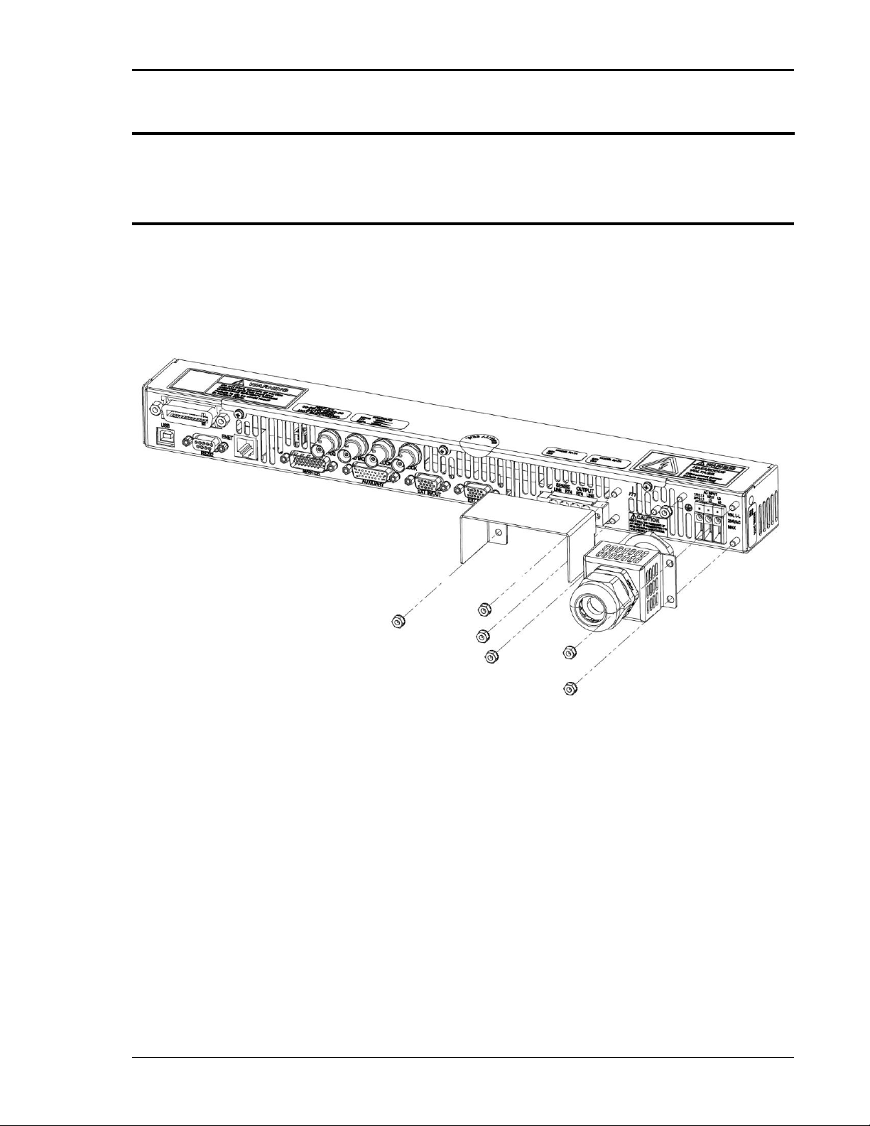
Asterion Series User Manual – 1U Models California Instruments
M330000-01, REV-G 35
3.3 Outline Drawings
Figure 3-3 and Figure 3-4 the outlines and overall dimensions for installation of the 1U models,
Enhanced and ATE, of the Asterion Series power source. Figure 3-2 shows the protective covers for the
AC input and AC/DC output. Figure 3-5 shows locations of rear panel connectors.
3.4 Rear Panel Protective Covers
Protective covers are provided for the rear panel AC input connector and AC/DC output connector. They
are installed to studs on the rear panel as shown in Figure 3-2, using M4-0.7 KEPS-nuts with a
maximum tightening torque of 1.1 Nm (10 lb-in). The components comprising the covers are supplied in
the ship kit.
Figure 3-2. Rear Panel Protective Cover Installation
Page 36

Asterion Series User Manual – 1U Models California Instruments
36 M330000-01, REV-G
Figure 3-3. Installation Drawing, Enhanced 1U Models
Page 37

Asterion Series User Manual – 1U Models California Instruments
M330000-01, REV-G 37
Figure 3-4. Installation Drawing, ATE 1U Models
Page 38

Asterion Series User Manual – 1U Models California Instruments
38 M330000-01, REV-G
3.5 Input/Output Connections
Refer to Figure 3-5 for the rear panel view of the 1U model power source showing the location of the
connectors.
Figure 3-5. Rear Panel View, 1U Models, (with GPIB and LKM/LKS options)
WARNING!
High voltage present at rear panel poses risk of electrical shock. The input and output
covers must be installed in bench top applications to maintain protection against
hazardous voltages. Do not remove protective covers on AC input or AC/DC output. Refer
installation and servicing to qualified personnel.
WARNING!
The input and output voltages at the rear panel of the unit are HAZARDOUS LIVE. When
rackmounting or panel-mounting the unit, suitable safeguards must be taken by the
installer to ensure that HAZARDOUS LIVE voltages are not operator accessible.
WARNING!
Capacitors in the power source might hold a hazardous electrical charge even if the power
source has been disconnected from the AC mains supply. Allow capacitors to discharge
to a safe voltage before touching exposed pins of mains supply connector.
WARNING!
A safety disconnect device for the AC mains input must be installed so that it is readily
accessible to the operator.
WARNING!
A properly sized input overcurrent protection device must be installed at the AC mains
input. It could be either a circuit breaker or fuse having a rating of 25% over the maximum
AC input line currents listed in the specifications of Section 2.1.4.
WARNING!
To prevent an electrical shock hazard, a safety ground wire must be connected from the
safety-ground stud on the rear panel to the AC mains earth protection-ground
Page 39

Asterion Series User Manual – 1U Models California Instruments
M330000-01, REV-G 39
3.6 AC Input Connection
The Asterion Series power source is designed to operate from 1-phase or 3-phase input power, having
2-wire/3-wire plus ground, with nominal AC input voltage (line-line or line-neutral) of
100/115/230/240 VAC, and 50/60/400 Hz input frequency. The AC input voltage range is automatically
selected by the unit at power-up; no user setup is required. Power factor correction (PFC) provides high
power factor, minimizing the required input apparent power and current harmonic distortion. Refer to the
specifications of Section 2.1.4 for AC input current requirements, and derating of output power as a
function of AC input voltage.
3.6.1 AC Input Overcurrent Protection
The Asterion Series power source has fuses at the AC input for fault protection. These fuses are internal
to the chassis, and are not user accessible. They provide fault isolation in case a failure occurs of
internal components or wiring. A suitable overcurrent protection device must be provided externally,
within the system installation, to protect the external wiring and interconnects.
3.6.2 AC Input Safety Disconnect Device
The Asterion Series power source front panel POWER switch does not disconnect the AC input line from
the unit. Ensure that an appropriately rated safety disconnect device is incorporated in the installation
that will provide isolation from the AC input when the device is opened. The device could be a switch or
circuit breaker, and must be located close to the unit, within reach of the operator, and clearly labeled as
the disconnection device.
3.6.3 AC Input Connector
The AC input connector, AC INPUT, is located on the rear panel, along with the safety-ground stud.
Figure 3-6 shows the rear panel view of the connector and stud. Table 3-1 shows the functions and
connector pinout, and Table 3-2 lists the connector type. A 1-Phase input is connected to terminals
L1/NEUT or L3/NEUT (do not connect from L1 to L3 to a 1-Phase source), while a 3-Phase input is
connected to L1/L2/L3 (the 3-Phase input is 3-wire plus ground and does not require a neutral
connection). The connector has compression terminals with female contacts. A ground connection must
always be made to the utility earth protection-ground using the rear panel safety-ground stud.
Figure 3-6. AC Input Connector and Safety-Ground
WARNING!
Do not connect to a 3-Phase source (3-wire plus ground) with line-to-line
voltage greater than 264 VAC, or between L1 and L3 to a 1-Phase source.
This could result in internal damage.
Page 40

Asterion Series User Manual – 1U Models California Instruments
40 M330000-01, REV-G
Name
Type
Range
Function
AC INPUT L1
AC Input
90-264 VAC
Line-1 input from utility AC mains;
For 1-Phase input, connect lines to
terminals L1 and NEUT, or L3 and NEUT;
connection from L1 to L3 is not allowed.
AC INPUT L2,
AC INPUT NEUT
AC Input
90-264 VAC
Line-2, NEUT input from utility AC mains.
For 1-Phase input, connect lines to
terminals L1 and NEUT, or L3 and NEUT;
connection from L1 to L3 is not allowed.
AC INPUT L3
AC Input
90-264 VAC
Line-3 input from utility AC mains;
For 1-Phase input, connect lines to
terminals L1 and NEUT, or L3 and NEUT;
connection from L1 to L3 is not allowed.
GND
Safety
Ground
N/A
Safety-Ground connection from utility earth
protection-ground.
Table 3-1. AC Input Connector Pinout and Safety-Ground
Connector
Type
AC Input
Phoenix P/N 1703050; 3-position, compression terminals;
wire stripping length: 14 mm (0.55”);
tightening torque: 0.5 Nm, min (4.4 lb-in) to 0.6 Nm, max (5.3 lb-in);
wire cross section: 0.5 mm2, min (20 AWG) to 6 mm2, max (10 AWG).
Safety-Ground
M4-0.7 x 7 mm stud; nut tightening torque, 1.1 Nm (10 lb-in), max.
Table 3-2. AC Input Connector Type
3.6.4 1-Phase AC Input Operation
Connect the utility AC mains wires to the rear panel AC input connector terminals, L1/NEUT or
L3/NEUT; do not connect to L1/L3. When using a 3-Phase source with line-to-line voltage greater that
264 VAC, ensure that the connection is from line to neutral so that the applied voltage is less than
264 VAC. For example, when connected to a 230 VAC/400 VAC WYE (4-wire plus ground) utility
source, connect from line to neutral, which would be 230 VAC. Use wires with ratings equal to or greater
than the current rating listed in the specifications of Section 2.1.4. A ground wire must be connected
from the rear panel safety-ground terminal to the utility power earth protection-ground.
3.6.5 3-Phase AC Input Operation
Connect the utility AC source wires to the rear panel AC input connector terminals, L1/L2/L3; a neutral
connection is not required. Ensure that the line-line voltage does not exceed 264 VAC. Use wires with
ratings equal to or greater than the current rating listed in the specifications of Section 2.1.4. A ground
wire must be connected from the rear panel safety-ground terminal to the utility power distribution earth
protection-ground.
CAUTION!
Do not connect an AC voltage that is greater than 264 VAC, either line-to-neutral
or line-to-line, for 1-Phase or 3-Phase inputs. Exceeding the maximum AC input
voltage could result in damage to the unit.
Page 41

Asterion Series User Manual – 1U Models California Instruments
M330000-01, REV-G 41
3.7 AC/DC Output Connection
The AC/DC Output connector provides terminations for the output and remote sense connections to the
load. A chassis functional-ground connection is provided adjacent to the connector to terminate cable
shields, if used. Refer to Figure 3-7 for a view of the connector, Table 3-3 for the pinout and functions,
and Table 3-4 for the connector type.
Figure 3-7. AC/DC Output Connector and Functional-Ground
Name
Type
Range
Function
Output LINE
Output
0-200/400 VAC;
0V to ±250/500 VDC
Connection of AC/DC output
Output RTN
Output
0-200/400 VAC;
0V to ±250/500 VDC
Connection of AC/DC output return
Sense LINE
Input
0-400 VAC;
0V to ±500 VDC
Remote sense connection for output
voltage
Sense RTN
Input
0-400 VAC;
0V to ±500 VDC
Remote sense return connection for
output voltage
GND
Functional
Ground
N/A
Connection to chassis for
functional-ground, such as termination
of cable shields
Table 3-3. AC/DC Output Connector Pinout and Functional-Ground
Connector
Type
AC/DC Output
Chassis connector header: Phoenix P/N 1720819; 4-position,
compression terminals;
Mating connector: Phoenix P/N 1777859; compression terminals;
housing retained to header with screws;
wire stripping length: 10 mm (0.39”);
tightening torque: 0.5 Nm, min (4.4 lb-in) to 0.8 Nm, max (7 lb-in);
tightening torque for ≤ 4 mm2 is 0.5 Nm to 0.6 Nm, > 4 mm2 is 0.7 Nm
to 0.8 Nm;
wire cross section: 0.2 mm2, min (24 AWG) to 6 mm2, max (10 AWG).
Functional-Ground
M4-0.7 x 7 mm stud; nut tightening torque, 1.1 Nm (10 lb-in), max.
Table 3-4. AC/DC Output Connector Type and Functional-Ground
Page 42

Asterion Series User Manual – 1U Models California Instruments
42 M330000-01, REV-G
3.8 Remote Sense
Output voltage sensing is user-selectable to be either local sense or remote sense. Sensing provides the
signal for measurement of the output voltage, and determines the physical point where the output
voltage is precisely regulated. Local sense is at the rear panel output connector, while remote sense is
at the load, through a cable connection from the rear panel remote sense connector. An internal relay is
used to select which sense signal is used by the controller.
Remote sensing is used to compensate for the voltage drop that occurs across the wires connecting the
load to the output of the power source. A separate pair of wires is routed to measure the voltage at the
terminals of the load where precise regulation of the output voltage is desired. The remote sense leads
are connected at the AC/DC Output connector on the rear panel; refer Figure 3-7. Connect the terminal,
Sense LINE, to the point at the load that is connected to the Output LINE terminal, and the terminal,
Sense RTN, to the point at the load that is connected to Output RTN terminal.
Special care is required in routing the sensing leads to prevent noise pickup or coupling to the power
leads; refer to Section 3.9. The sense leads should be a twisted-pair of at least AWG #22 wire, and may
require shielding in high noise environments. If a shield is used, connect it to the functional-ground
terminal at the AC/DC Output connector location.
If the remote sense leads are not connected, but remote sense has been selected, the AC source will
continue to operate but the voltage at the load will no longer be precisely regulated. An internal circuit
exists within the unit that provides redundant voltage sensing from the output terminals, in case the
remote sense leads are not connected. However, this condition does not have voltage calibration, and
since the voltage is now measured at the output terminals, the voltage drop of the load wiring would no
longer be compensated.
Two conditions related to remote sensing are treated as faults and result in shutdown of the output:
short-circuiting of the remote sense terminals or connecting the remote sense leads in reverse polarity.
When the fault condition is detected, shutdown will result with the output voltage being programmed to
zero and the output isolation relays being opened.
3.9 Noise and Impedance Effects
To minimize noise pickup or radiation from load circuits, load wires and remote sense wires should be
twisted-pair and have minimum lead length. Shielding of the sense leads may be necessary in high
noise environments. Even if noise is not a concern, the load and remote sense wires should be
twisted-pairs to reduce coupling between them, which could impact the stability of the output amplifier.
Twisting the load wires provides an additional benefit in reducing the parasitic inductance of the cable.
This improves the dynamic response characteristics at the load by maintaining low source impedance at
high frequencies. If connectors are utilized for the power and sense leads, consideration of routing is
necessary to minimize coupling between the leads. Ensure that the connector terminals for the sense
leads are in adjacent contact locations, and minimize the physical loop area of the untwisted portions.
Page 43

Asterion Series User Manual – 1U Models California Instruments
M330000-01, REV-G 43
3.10 Wire Gauge Selection
Care must be taken to properly size all conductors for the input and output of the power source. This
section provides guidance in the selection of wire size.
CAUTION!
Use wire with Class B or C stranding. Fine-stranded (flexible) wire should not be used
unless crimp-on lugs or ferrules are utilized that are approved for fine-stranded cables
3.10.1 Wire Size
The tables below will assist in determining the appropriate wire size for both the input and output
connections. Table 3-5 gives minimum recommended wire size; these recommendations are for 30°C
ambient, and for copper wire only. This table is derived from the National Electrical Code, and is for
reference only. Local laws and conditions may have different requirements. For higher ratings, wires
can be paralleled; refer to the National Electrical Code for guidelines.
Size
Temperature Rating of Copper Conductor
AWG
60°C
75°C
90°C
Types: TW, UF
Types: RHW,
THHW, THW,
THWN, XHHW,
USE, ZW
Types: TBS SA,
SIS, FEP, FEPB, MI,
RHH, THHN,
THHW, XHH, XHHW
Current Rating, A(RMS)
18 − −
14
16 − −
18
14
15
20
25
12
20
25
30
10
30
35
40
8
40
50
55
6
55
65
75
4
70
85
95
3
85
100
115
2
95
115
130
1
110
130
145
0
125
150
170
00
145
175
195
000
165
200
225
0000
195
230
260
Table 3-5. Minimum Wire Size
Page 44

Asterion Series User Manual – 1U Models California Instruments
44 M330000-01, REV-G
When determining the optimum cable specification for your power applications, the same engineering
rules apply whether at the input or output of an electrical device. Therefore, this guide applies equally to
the input cable and output cable for this power source and application loads.
Power cables must be able to safely carry maximum load current without overheating or causing
insulation degradation. It is important to power source performance to minimize IR (voltage drop) loss
within the cable. These losses have a direct effect on the quality of power delivered to and from the
power source and corresponding loads.
When specifying wire gauge, consider derating due to operating temperature at the wire location. Wire
gauge current capability and insulation performance drops with the increased temperature developed
within a cable bundle and with increased environmental temperature. Therefore, short cables with
derating of gauge size and insulation properties are recommended for power source applications.
Be careful when using published commercial utility wiring codes. These codes are designed for the
internal wiring of homes and buildings and accommodate the safety factors of wiring loss, heat,
breakdown insulation, aging, etc. However, these codes consider that up to 5% voltage drop is
acceptable. Such a loss directly detracts from the performance specifications of this power source. Also,
consider how the wiring codes apply to bundles of wire within a cable arrangement.
In high performance applications requiring high inrush/ transient currents, additional consideration is
required. The cable wire gauge must accommodate peak currents developed at peak voltages, which
might be up to five times the RMS current values. An underrated wire gauge adds losses, which alter the
inrush characteristics of the application and thus the expected performance.
Table 3-6 presents wire resistance and resulting cable voltage drop at maximum rated current, with the
wire at 20°C. Copper wire has a temperature coefficient of α = 0.00393Ω/°C at t1 = 20°C, so that at an
elevated temperature, t2, the resistance would be R2 = R1 (1 + α (t2 - t1)).
The output power cables must be large enough to prevent the line voltage drop (total of both output
wires) between the power source and the load from exceeding the remote sense capability as presented
in the specification section. Calculate the voltage drop using the following formula:
Voltage Drop = 2 × distance-in-feet × cable-resistance-per-foot × current
Size,
AWG
A(RMS),
(90°C wire)
Ohms/100 Ft,
(One Way)
Voltage Drop/100 Ft,
(Column 2 x Column 3)
18
14
0.639
8.95
16
18
0.402
7.24
14
25
0.253
6.33
12
30
0.159
4.77
10
40
0.100
4.00
8
55
0.063
3.47
6
75
0.040
3.00
4
95
0.025
2.38
3
115
0.020
2.30
2
130
0.016
2.08
1
145
0.012
1.74
0
170
0.0098
1.67
00
195
0.0078
1.52
000
225
0.0062
1.40
0000
260
0.0049
1.27
Table 3-6. Wire Resistance and Voltage Drop, 20°C
Page 45

Asterion Series User Manual – 1U Models California Instruments
M330000-01, REV-G 45
3.11 Rear Panel User Interface Connectors
The rear panel contains the connectors for the remote analog and discrete-digital control interfaces,
master/auxiliary unit interface, the digital communications interfaces (LAN, USB, RS-232C, and optional
IEEE-488), and the external interface.
3.11.1 External Input/Output Control Signal Connector
The External Input/Output connector, EXT IN/OUT, is located on the rear panel. Figure 3-8 shows the
rear panel view of the connector, and Table 3-7Table 3-7. External Input/Output Control Connector Type
lists the connector type. Table 3-8 Table 3-8 shows the functions and Table 3-9 shows the connector
pinout.
Figure 3-8. External Input/Output Control Connector
Connector
Type
External Input/Output Control
High-density, 15-socket, receptacle (female) Subminiature-D.
Table 3-7. External Input/Output Control Connector Type
Page 46

Asterion Series User Manual – 1U Models California Instruments
46 M330000-01, REV-G
Function
Characteristics
External Analog
Programming of
Output Voltage
Waveform
Signal input for output voltage waveform programming by external analog reference;
AC or DC input signal: 0V to user-selectable maximum range value within ±2.5 V(PK) to
±10 V(PK), corresponding to maximum range of 1.77 V(RMS) to 7.07 V(RMS), for zero to
full-scale RMS output voltage; with AC waveform, from 16 Hz to 5 kHz (option dependent);
programming accuracy, ±2% of full-scale output;
input impedance, 40 kΩ, typical;
safety isolation SELV-rated, referenced to chassis;
this function has the same connector pin connection as the signal, External Analog
Programming of Output Voltage Amplitude; that pin is user-selectable as to which function
is provided.
External Analog
Programming of
Output Voltage
Amplitude (RPV)
Signal input for output voltage amplitude programming of waveform that is set by internal
controller reference;
DC input signal: 0V to user-selectable maximum range value within 2.5 VDC to10 VDC, for
zero to full-scale RMS of internally programmed output voltage waveform;
programming accuracy, ±2% of full-scale output;
input impedance, 40 kΩ, typical;
safety isolation SELV-rated, referenced to chassis;
this function has the same connector pin connection as the signal, External Analog
Programming of Output Voltage Waveform; that pin is user-selectable as to which function
is provided.
External Analog
Modulation of
Output Voltage
Signal input for output voltage modulation of waveform set by internal controller reference;
AC or DC input signal range: 0V to ±7.07 V(PK), 0-5 V(RMS) for 0-20% of full-scale output
voltage amplitude modulation;
programming accuracy, ±2% of full-scale output;
input impedance, 40 kΩ, typical;
safety isolation SELV-rated, referenced to chassis.
Trigger Input
Signal input of external trigger for execution of programmed values or transient lists;
logic level, TTL-compatible;
isolated connection with signal return common to the signals, Synchronization Signal and
Remote Inhibit; safety isolation SELV-rated, referenced to ISO_COM (refer to Table 3-9).
Synchronization
Signal (SYNC)
Input
Signal input for external square wave to control the output frequency and phase, with the
waveform generated by the internal reference;
logic level, TTL-compatible; logic-high-going edge synchronized with positive-going
alternation of output waveform;
isolated connection with signal return common to the signals, Trigger Input and Remote
Inhibit; safety isolation SELV-rated, referenced to ISO_COM (refer to Table 3-9).
Remote Inhibit
Input
Signal input to turn the output off/on; logic level, TTL-compatible; user-selectable for
active-high or active-low;
isolated connection with signal return common to the signals, Synchronization Clock and
Trigger Input; safety isolation SELV-rated, referenced to ISO_COM (refer to Table 3-9).
Summary Fault
Switch Output
Switch output indicating that a Summary Fault (DFI) condition is present;
normally-closed, bidirectional AC/DC solid-state switch;
closed-circuit for fault or when unit is turned off (open-circuit for no fault present);
switch ratings: ±12V, maximum peak voltage; 0.1A, maximum current; 2.5Ω, maximum
closed resistance; 6µA, maximum open-circuit leakage current at 12V;
connection isolated from all other signals, floating switch output;
safety isolation SELV-rated.
Table 3-8. External Input/Output Control Functions
Page 47

Asterion Series User Manual – 1U Models California Instruments
M330000-01, REV-G 47
Pin #
Name
Type
Range
Function
1
REFERENCE
Analog
Input
±10V
Analog programming signal input terminal for
user-selectable external waveform programming or
amplitude control (RPV).
2
N/A
N/A
N/A
Not Used
3
N/A
N/A
N/A
Not Used
4
REFERENCE
RETURN
Signal
Return
Return
Analog programming signal return terminal.
5
MODULATION
Analog
Input
±7.07V
External modulation signal input terminal.
6
N/A
N/A
N/A
Not Used
7
N/A
N/A
N/A
Not Used
8
MODULATION
RETURN
Signal
Return
Return
External modulation signal return terminal.
9
ISO_COM
Return
Return
Isolated signal return terminal for signals on Pin-12 and
Pin-13; connected to Pin-11 through 10 Ω;
isolated from Pins1-8 and Pins14-15.
10
SYNC_HIGH
Digital
Input
0-5V
Isolated signal for synchronization of the output to a
logic-high signal transition; paired with Pin-11;
isolated from Pins1-8 and Pins14-15.
11
SYNC_LOW
Return
Return
Isolated signal return for synchronization of the output;
paired with Pin-10; connected to Pin-9 through 10 Ω;
isolated from Pins1-8 and Pins14-15.
12
INHIBIT
Digital
Input
0-5V
Isolated inhibit signal to turn the output off/on and
open/close the output relay; signal return on Pin-9;
isolated from Pins1-8 and Pins14-15.
13
TRIGGER
Digital
Input
0-5V
Isolated trigger signal; signal return on Pin-9;
isolated from Pins1-8 and Pins14-15.
14
SUMMARY
FAULT-1
Switch
Output
±12V
Isolated Summary Fault (DFI) signal; paired with Pin-15;
isolated from Pins1-13; refer to Table 3-8.
15
SUMMARY
FAULT-2
Switch
Output
±12V
Isolated Summary Fault (DFI) signal return; paired with
Pin-14; isolated from Pins1-13; refer to Table 3-8.
Table 3-9. External Input/Output Control Connector Pinout
3.11.2 Summary Fault Signal (DFI)
The Summary Fault (DFI) signal, SUMMARY FAULT-1 (Pin-14) and SUMMARY FAULT-2 (Pin-15),
provides an indication that an abnormal condition has occurred. In the default configuration, the signal
reports the summary bit that is the logic-OR of the Questionable Status Register outputs for the following
events:
a. PFC Module fault: summary state of overtemperature, input undervoltage, overload;
b. DC Module fault: summary state of overtemperature, output overvoltage, driver fault;
c. AC Module fault: summary state of overtemperature, DC bus under/overvoltage, inverter
peak current limit, logic power undervoltage;
d. Overtemperature fault: AC Module overtemperature;
e. Output overvoltage fault;
f. Output voltage regulation fault;
g. Output current-limit fault.
Page 48

Asterion Series User Manual – 1U Models California Instruments
48 M330000-01, REV-G
The functionality of the Summary Fault (DFI) signal could be programmed through SCPI commands to
report events as captured in either of the following sources: Questionable Status Register (default
setting), Operation Status Register, Standard Event Status Register, or Request Service Summary Bit.
Also, the Summary Fault signal operation could be enabled and disabled through SCPI commands.
Refer to the Asterion Series SCPI Programming Manual, M330100-01, for specific information on the
programming options; it is referred to as the Discrete Fault Indicator (DFI) signal in that manual.
3.11.3 Remote Inhibit Signal
The Remote Inhibit signal, /INHIBIT_ISO (Pin-12), can be used to turn the output on/off and close/open
the output relay of the power source. When set to the off state, this input overrides the output state
programmed through the front panel or the remote digital interface.
The default logic-level for Remote Inhibit is a logic-low or contact closure between /INHIBIT_ISO (Pin-12)
and ISO_COM (Pin-9). This will cause the output voltage to be programmed to zero volts and the output
relays to open. This logic-level could also be selected with the SCPI command, OUTPUT:RI:LEVEL LOW.
Alternatively, the logic-level could be changed by the user to logic-high using the remote digital interface
SCPI command, OUTPUT:RI:LEVEL HIGH. A logic-high or open-circuit between /INHIBIT_ISO (Pin-12) and
ISO_COM (Pin-9) will cause the output voltage to be programmed to zero volts and the output relays to
open.
The mode of operation of the Remote Inhibit can be changed using the remote digital interface SCPI
command, OUTP:RI:MODE <mode>. The following modes can be selected:
LATC(hing) A TTL logic-low (or user-selected logic-high) at the Remote Inhibit input latches
the output in the protection shutdown state; this state could only be cleared by
the remote digital interface SCPI command, OUTPut:PROTection:CLEar.
LIVE The output state follows the state of the Remote Inhibit input. A TTL logic-low
(or user-selectable logic-high) at the Remote Inhibit input turns the output off; a
TTL logic-high (or user-selectable logic-low) turns the output on.
OFF The power source ignores the Remote Inhibit input.
The Remote Inhibit output mode state is saved at power-down. The factory default state is LIVE. For
additional information on programming the Remote Inhibit function, refer to the Asterion Programming
Manual P/N M330100-01 distributed on the CD, CIC496. Refer to AMETEK Programmable Power
website, www.powerandtest.com, to download latest version.
3.11.4 External Interface Signal Connector
The External Interface connector, EXT INTFC, is located on the rear panel. Figure 3-9 shows the rear
panel view of the connector, and Table 3-10Table 3-10. External Interface Signal Connector Type lists
the connector type. This connector provides a dedicated interface with an extension chassis, and does
not have any signals that are to be utilized by the user.
Figure 3-9. External Interface Signal Connector
Connector
Type
External Interface
High-density, 15-socket, receptacle (female) Subminiature-D.
Table 3-10. External Interface Signal Connector Type
Page 49

Asterion Series User Manual – 1U Models California Instruments
M330000-01, REV-G 49
3.11.5 Command Monitor and Trigger Output Connectors
The connectors for the Command Monitor, CMD MON, and Trigger Output, TRIG, signals are BNC-type
located on the rear panel; refer to Figure 3-10 for view of connectors and Table 3-11 for descriptions.
The CMD MON connector provides a signal output for sensing the waveform of the internal voltage
command signal that is being applied to the power amplifier. The TRIG connector provides a signal
output synchronized with changes in programmed value or transient lists.
Figure 3-10. External Command Monitor and Trigger Output Connectors
Function
Characteristics
Output Command Monitor
Signal output for monitoring the waveform of the voltage command
signal of the output amplifier;
0 -5 V(RMS), typical, signal range for zero to full-scale output voltage;
individual rear panel BNC connector;
safety isolation SELV-rated, referenced to chassis.
Trigger Output
Signal output with dual function: user-selectable as either function
trigger or list trigger; function trigger provides a pulse for any
programmable change in output voltage or frequency; list trigger
provides a pulse if programmed as part of list transients;
logic level, active-low pulse with duration of 500 µs, typical;
individual rear panel BNC connector;
safety isolation SELV-rated, referenced to chassis.
Table 3-11. External Command Monitor and Trigger Output Characteristics
3.11.6 Clock and Lock Connectors (Option)
The connectors for the Clock signal, CLOCK, and Lock signal, LOCK, are BNC-type located on the rear
panel; refer to Figure 3-11 for view of connectors and Table 3-12 for descriptions. These connectors are
only available with the LKM or LKS options. These options are used to synchronize and control the
phase shift of the output voltage of Auxiliary power sources in relation to the output of the Master power
source. The frequency of the Auxiliary power sources is determined by the frequency of the Master
source through the CLOCK signal; the phase is determined by the LOCK signal. Figure 3-16 shows an
example of CLOCK and LOCK connections in a multi-phase system comprised of three power sources.
Figure 3-11. External Clock/Lock Interface Connectors (Option)
Page 50

Asterion Series User Manual – 1U Models California Instruments
50 M330000-01, REV-G
Function
Characteristics
LKM (Option)
Signal outputs in Master unit for Clock and Lock that are used to synchronize two or more
AC sources; CLOCK sets the frequency, while LOCK sets the phase; logic level,
TTL-compatible; individual rear panel BNC connectors for each signal; safety isolation
SELV-rated, referenced to chassis.
LKS (Option)
Signal inputs in Auxiliary units for Clock and Lock that are used to synchronize two or more
AC sources; CLOCK sets the frequency, while LOCK sets the phase; logic level,
TTL-compatible; individual rear panel BNC connectors for each signal; safety isolation
SELV-rated, referenced to chassis.
Table 3-12. External Clock/Lock Interface Characteristics (Option)
3.11.7 Master/Auxiliary System Interface Connectors
The Master connector, MASTER, and Auxiliary connector, AUXILIARY, are used to connect Auxiliary
power sources to the Master power source for operation in parallel, multi-chassis systems; refer to
Figure 3-12 for view of connectors, with Table 3-13 and Table 3-14 for descriptions. The Master/Auxiliary
interface signals are dedicated to the control of parallel-group operation, and are not to be utilized by the
user.
The power source that is to be the Master will have the System Interface cable plugged into its
connector labeled MASTER. The other end of the System Interface cable will plug into the connector
labeled AUXILIARY in the first Auxiliary power source comprising the system. Additional Auxiliary power
sources would be chained together with System Interface cables connecting the MASTER connector of
one unit to the AUXILIARY connector of the next unit in the chain. Refer to Figure 3-17 for an example of
a parallel system comprised of three units.
Figure 3-12. External Master/Auxiliary System Interface Connectors
Connector
Type
Master
High-density, 26-pin, plug (male) Subminiature-D.
Auxiliary
High-density, 26-socket, receptacle (female) Subminiature-D.
Table 3-13. External Master/Auxiliary System Interface Connector Type
Page 51

Asterion Series User Manual – 1U Models California Instruments
M330000-01, REV-G 51
Function
Characteristics
Master Interface
Control signal interface on Master unit (or other Auxiliary unit if more
than two units comprise the parallel-group) going to Auxiliary unit for
multi-chassis parallel operation;
Connector: high-density, 26-pin, male Subminiature-D; none of the
signals are intended for interface with user equipment.
Auxiliary Interface
Control signal interface on Auxiliary unit coming from Master unit (or
other Auxiliary unit if more than two units comprise the parallel-group)
for multi-chassis parallel operation;
Connector: high-density, 26-socket, female Subminiature-D; none of the
signals are intended for interface with user equipment.
Table 3-14. External Master/Auxiliary System Interface Characteristics
3.11.8 RS-232C Serial Interface Connector
RS-232C remote control interface is made through a 9-contact Subminiature-D connector located on the
rear panel; refer to Figure 3-13 for view of connector and Table 3-15 with Table 3-16 for descriptions.
The power source functions as Data Circuit-terminating Equipment (DCE). The cable connecting to the
Data Terminal Equipment (DTE) should be straight-through (one-to-one contact connections).
Figure 3-13. RS-232C Interface Connector
Connector
Type
RS-232C Interface
9-contact receptacle (female) Subminiature-D.
Table 3-15. RS-232C Interface Connector Type
Pin #
Name
DCE Signal
Direction
1
N/C
N/A
N/A 2 TxD
Transmit Data
Output
3
RxD
Receive Data
Input
4
N/C
N/A
N/A
5
Common
N/A
N/A 6 N/C
N/A
N/A 7 RTS
Request To Send
Input
8
CTS
Clear To Send
Output
9
N/C
N/A
N/A
Table 3-16. RS-232C Interface Connector Pinout
Page 52

Asterion Series User Manual – 1U Models California Instruments
52 M330000-01, REV-G
3.11.9 USB Interface
USB remote control interface is made through a Series-B device connector located on the rear panel;
refer to Figure 3-14 for view of connector and Table 3-17 and Table 3-16 for descriptions. A standard
USB cable between the Asterion Series power source and a computer should be used.
.
CAUTION!
Connecting the power source to the computer controller through an USB hub is not
recommended. The USB connection should be direct between the two devices.
Figure 3-14. USB Interface Connector
Pin #
Name
Description
1
N/C
No Connection
2
D-
Data -
3
D+
Data +
4
GND
Ground
Table 3-17. USB Interface Connector Pinout
Page 53

Asterion Series User Manual – 1U Models California Instruments
M330000-01, REV-G 53
3.11.10 LAN Interface (Ethernet)
A LAN connector (Ethernet 10BaseT/100BaseT) is located on the rear panel for remote control; refer to
Figure 3-15 for view of connector and Table 3-18 and Table 3-16 for descriptions. A standard modular
cable with an 8P8C modular plug should be used between the power source and a network hub. For a
direct connection to a computer LAN card, a crossover cable with an 8P8C modular plug is required.
The MAC Address (Media Access Control) of the Ethernet port is printed on a label on the chassis of the
power source. For information on how to set up a network connection or a direct computer connection
using the LAN interface, refer to the Asterion Series Programming Manual P/N M330100-01 distributed
on the CD, CIC496. Refer to AMETEK Programmable Power website, www.powerandtest.com, to
download latest version.
Figure 3-15. LAN Interface 8P8C Modular Connector
Pin #
Ethernet Signal
EIA/TIA 568A
EIA/TIA 568B
Crossover
1
Transmit/Receive Data 0 +
White with green stripe
White with orange stripe
2
Transmit/Receive Data 0 -
Green with white stripe or
solid green
Orange with white stripe or
solid orange
3
Transmit/Receive Data 1 +
White with orange stripe
White with green stripe
4
Transmit/Receive Data 2 +
Blue with white stripe or
solid blue
Blue with white stripe or
solid blue
5
Transmit/Receive Data 2 -
White with blue stripe
White with blue stripe
6
Transmit/Receive Data 1 -
Orange with white stripe or
solid orange
Green with white stripe or
solid green
7
Transmit/Receive Data 3 +
White with brown stripe or
solid brown
White with brown stripe or
solid brown
8
Transmit/Receive Data 3 -
Brown with white stripe or
solid brown
Brown with white stripe or
solid brown
Table 3-18. LAN Interface 8P8C Modular Connector Pinout
Page 54

Asterion Series User Manual – 1U Models California Instruments
54 M330000-01, REV-G
3.12 Multiple Chassis System Configurations
The Asterion Series power source has the capability to be configured in multi-chassis groups with
multiple-phase outputs using the optional Clock/Lock signal interface. The sources are individually
programmed for output voltage/current, while the Clock/Lock interface ensures frequency and phase
synchronization between units.
The power source could also be configured in parallel, multiple-chassis groups to extend the total output
power. The outputs of the individual units must be connected in parallel, and a Master/Auxiliary System
interface cable must interconnect them. The control interface of the units is automatically configured
when the Master/Auxiliary System interface cable is connected, so no setting changes by the user are
required.
3.12.1 Multi-Phase System
Refer to Figure 3-16 for the connections that are required to set up a multi-phase group of units; the
example shown is for a 3-Phase system. The output lines, LINE and RTN, are connected independently
from each output of a unit to the load. If the remote sense is used, each unit must have it connected to
the phase of the load at the point where precise regulation of the output voltage is desired.
The units must have the Clock/Lock options installed, with the Master unit having the LKM option and
the Auxiliary units having the LKS option. The Clock/Lock connectors of the Master unit provide output
signals: CLOCK to set the frequency, and LOCK to set the phase. The Clock/Lock connectors of the
Auxiliary units are inputs to accept the control signals from the Master unit. The Clock and Lock
interfaces are signal buses, so the Clock connectors of all units must be connected, and the Lock
connectors must be connected together. Programming, readback, and control are done through the
individual units. Also, the Auxiliary units must have their phase programmed in reference to the Master
unit.
The clock source and configuration must be set for multi-phase operation through the remote digital
interface using SCPI commands or the front panel display. Set up through the front panel is as follows:
1. In the CONFIGURATION, PONS CLOCK CONFIG display menu, the Master unit must have the
configuration set to Master (the AC input must be cycled off/on for a change in a PONS setting
to take effect); refer to Section 4.6.5;
2. In the CONFIGURATION, PONS CLOCK CONFIG display menu, the Auxiliary units must have
the configuration set to Auxiliary (the AC input must be cycled off/on for a change in a PONS
setting to take effect); refer to Section 4.6.5;
3. In the CONFIGURATION, CLOCK MODE display menu, the Auxiliary units must have the clock
source set to External; refer to Section 4.6.5.
Page 55

Asterion Series User Manual – 1U Models California Instruments
M330000-01, REV-G 55
Figure 3-16. Connections for 3-Phase Master/Auxiliary Group, 1U Models
3.12.2 Parallel System
Refer to Figure 3-17 for the connections that are required to set up a parallel group of units. The output
lines, LINE and RTN, are connected together from each unit to an external terminal block. If the remote
sense is used, only the Master unit has it connected to the load at the point where precise regulation of
the output voltage is desired; the Auxiliary units do not have remote sense connected. The
Master/Auxiliary System Interface cable is connected from the Master unit connector, MASTER, to the
Auxiliary unit connector, AUXILIARY. Additional Auxiliary units are connected from the Master connector
of the last unit in the signal chain to the Auxiliary connector of following unit.
Units of either 750 W or 1500 W rating could be connected in any combination to form a parallel group.
Units with a 500 W rating must be paralleled only to units with the same rating. All programming,
readback, and control are done through the Master unit. The Master/Auxiliary interface is automatically
configured so that the current reported by the Master unit is the sum of all units within the group. The
displays of the Auxiliary units are disabled, and show the message, “SOURCE IN AUXILIARY MODE No
access to the user”.
When the parallel group system is powered up, the order of powering the Auxiliary sources and the
Master source is not important. After the system is powered up, if an Auxiliary power source is powered
down there will be an error message displayed on the Master source, “Aux Down ensure all are powered
up”. If power is reapplied to the Auxiliary source, the message will disappear and normal operation could
resume. If the Master/Auxiliary System Interface cable is removed from the Auxiliary source while the
source is powered down, the error message will disappear, but the Master source will not have the
correct configuration. The Master source must have its AC input power toggled, Off to On, for the correct
configuration to be established.
Page 56

Asterion Series User Manual – 1U Models California Instruments
56 M330000-01, REV-G
Figure 3-17. Connections for 1-Phase Parallel Group, 1U Models
Page 57

Asterion Series User Manual – 1U Models California Instruments
M330000-01, REV-G 57
4. Operation
The Asterion Series power source provides extensive functionality and programmability, which could be
utilized through the front panel, remote digital interface, and the remote analog/digital control interface.
The front panel includes a graphical, touch-screen display utilizing a menu-driven interface for simplified
operation of the unit and quick access to the sophisticated functions. The remote interfaces provide
expanded control capability and access to the full functionality of the source. The following sections
provide detailed information on the controls and indicators, front panel menu structure, and remote
digital interface programming conventions.
4.1 Front Panel Operation
Figure 4-1 shows a view of the front panel of the Enhanced models, while Figure 4-3 shows the front
panel of the ATE models. Refer to Table 4-1 for functional descriptions of the Enhanced front panel, and
Table 4-2 for functional descriptions of the ATE front panel.
Figure 4-1. Front Panel, Enhanced 1U Models
Figure 4-2. Front Panel, ATE 1U Models
Page 58

Asterion Series User Manual – 1U Models California Instruments
58 M330000-01, REV-G
4.1.1 Front Panel Controls and Indicators, Enhanced 1U Models
Item
Reference
Functional Description
1
ON/OFF(Standby) Switch
Two–position pushbutton switch turns the source on and off.
WARNING!
OFF position does not remove AC input from
internal circuits. Disconnect external AC input before
servicing unit
2
OUTPUT Switch
Momentary switch that toggles the output power ON/OFF, and
closes/opens the output isolation relay.
3
Display
TFT color graphics display with backlight and pressure-actuated
touch-screen;
menu-driven settings and functions.
4
Rotary Encoder
Navigates between and within screens; scrolls through functions and
selects numerical values; adjusts output parameters in real-time.
5
Rotary Encoder Switch
Momentary-action switch that selects functions and enters numerical
values.
LED Mode Indicators
Indicates the mode that is active:
6
OUTPUT
Output is turned on; indicator is integral with the OUTPUT switch.
7
HI RNG
The output voltage is set to the high-range.
8
CV
Power supply is presently in Constant-Voltage mode, and the output
voltage is regulated.
9
CC
Power supply is presently in Constant-Current mode, and the output
current is regulated.
10
REM
Source is presently controlled by the remote digital interface. If the
RS-232C, USB or LAN interface is used, the REM state can be enabled
by the external controller using the SCPI command, SYST:REM. If the
optional IEEE-488 (GPIB) interface is used, this indicator will be lit
whenever the REM line (REM ENABLE) line is asserted by the IEEE-488
controller.
Any time the REM LED is lit, the front panel control of the unit is
disabled. To regain control through the front panel, the external controller
must send the SCPI command, SYST:LOC.
11
FAULT
Fault condition has occurred; output is shutdown, isolation relay is open,
and output voltage is programmed to zero.
Table 4-1. Front Panel Controls and Indicators, Enhanced 1U Models
Page 59

Asterion Series User Manual – 1U Models California Instruments
M330000-01, REV-G 59
4.1.2 Front Panel Controls and Indicators, ATE 1U Models
Item
Reference
Functional Description
1
ON/OFF(Standby) Switch
Two–position pushbutton switch turns the source on and off.
WARNING!
OFF position does not remove AC input from
internal circuits. Disconnect external AC input before
servicing unit.
2
UPDATE Switch
Momentary switch that enables the boot-loader when it is depressed
while the unit is being powered on with the AC input.
LED Mode Indicators
Indicates the mode that is active:
3
POWER
AC input power is turned on to the unit.
4
OUTPUT
Output is turned on.
5
HI RNG
The output voltage is set to the high-range.
6
FAULT
Fault condition has occurred; output is shutdown, isolation relay is
open, and output voltage is programmed to zero.
7
CC
Power supply is presently in Constant-Current mode, and the output
current is regulated.
8
CV
Power supply is presently in Constant-Voltage mode, and the output
voltage is regulated.
9
REM/LAN
Source is presently controlled by the remote digital interface. If the
RS-232C, USB or LAN interface is used, the REM state can be enabled
by the external controller using the SCPI command, SYST:REM. If the
optional IEEE-488 (GPIB) interface is used, this indicator will be lit
whenever the REM line (REM ENABLE) line is asserted by the
IEEE-488 controller.
Any time the REM LED is lit, the front control of the unit is disabled. To
regain control through the front panel, the external controller must send
the SCPI command, SYST:LOC.
With LAN interface, the REM/LAN indicator also provides LXI status
Table 4-2. Front Panel Controls and Indicators, ATE 1U Models
Page 60

Asterion Series User Manual – 1U Models California Instruments
60 M330000-01, REV-G
4.2 Basic Output Programming
For basic operation, the power source requires selection of the output voltage type (AC, DC, or AC+DC),
voltage range (Low-Range or High-Range), the mode of operation (CV/CC or CV/CL modes), and
adjustment of the output parameters (voltage, current, frequency, and DC offset). This could be
accomplished through the front panel display by navigating to the appropriate menu, entering the
desired values, and enabling the output. Alternately, the remote digital interface could be used with SCPI
commands or the Asterion Virtual Panels. Refer to the Asterion Series Programming Manual P/N
M330100-01 (distributed on the CD, CIC496), or refer to the AMETEK Programmable Power website,
www.powerandtest.com, to download latest versions.
4.2.1 Front Panel Display Navigation
The selection of the output characteristics and adjusting the output parameters through the front panel
display could be accomplished using the DASHBOARD screen (refer to Figure 4-13) or the OUTPUT
PROGRAM screen (refer to Figure 4-16). The selection and adjustment of items could be done using
either the touch-screen or rotary encoder:
1. Using the touch-screen or rotary encoder, navigate (refer to Section 4.4.2 and Section 4.4.3) to
the HOME Screen-1, and select the OUTPUT PROGRAM screen (refer to Figure 4-12).
2. Within the OUTPUT PROGAM screen, select the parameter, and adjust its value.
3. The DASHBOARD screen provides an alternate means of adjusting the primary parameters,
voltage, current, and frequency, in the same menu. It is also located in HOME Screen-1. It has
the additional functionality of real-time adjustment of the parameters as the encoder is rotated
(refer to Section 4.6.1.1).
4.2.2 Selecting Output Characteristics and Adjusting Parameters
To set up the power source for basic operation with either a sine wave or DC output, perform the
following sequence:
1. Navigate to the AC/DC menu in the OUTPUT PROGRAM screen, and select the output voltage
type: either AC, DC, or AC+DC.
2. Navigate to the VOLTAGE RANGE menu in the OUTPUT PROGRAM screen, and select the
output range: either Low-Range or High-Range.
3. Navigate to the REGULATION menu in the OUTPUT PROGRAM screen, and select the output
voltage/current regulation: either CV/CC or CV/CL.
4. Navigate to the VOLTAGE menu in the OUTPUT PROGRAM screen, and adjust the output
voltage value.
5. If the AC+DC voltage type had been selected, navigate to the DC OFFSET menu in the
OUTPUT PROGRAM screen, and adjust the DC component of the output voltage.
6. Navigate to the CURRENT menu in the OUTPUT PROGRAM screen, and adjust the output
current value.
7. Navigate to the FREQUENCY menu in the OUTPUT PROGRAM screen, and adjust the output
frequency value.
8. The output could be turned on with the front panel OUTPUT switch.
Page 61

Asterion Series User Manual – 1U Models California Instruments
M330000-01, REV-G 61
4.3 Basic Functional Test
WARNING!
When performing the functional tests, exercise appropriate care to protect
against hazardous voltages that are present on the input and output.
Refer to Figure 4-3 for a functional test setup for connecting the output load, remote sense, and test
equipment to the power source.
1. Connect an oscilloscope and DVM to the power source AC/DC Output connector.
Recommended equipment: oscilloscope, Tektronix TDS 3034C with P5202A high-voltage
differential probe; DVM, Keysight 34461A.
2. With the AC mains verified as being off, make the AC input voltage connections to the power
source input connector.
3. Turn on the AC mains, and then turn on the POWER switch on the power source front panel.
4. Verify that the front panel LCD display lights up, or, in the ATE models, the POWER LED. After
several seconds the display should show the DASHBOARD Screen Top-Level Menu or the
Default screen; refer to Section 4.6 for description of menus.
5. Switch on the resistive load that is set to draw 90% of full-scale current at 200 V(RMS) for the
low-range AC output.
6. Using the front panel display or remote digital interface, set the output for AC mode operation
with the following parameters: voltage mode = AC; voltage range = low, 200 V;
output voltage = 200 V(RMS); frequency = 60 Hz; and current setting = full-scale for the
particular model being tested. Ensure that the Constant-Voltage/Current-Limit mode is selected
in the REGULATION menu of the OUTPUT PROGRAM Screen Top-Level Menu-2; refer to
Section 4.6 for description of menus.
7. Enable the output by tapping the OUTPUT switch. The OUTPUT LED in the switch button will
turn on when the output is on.
8. Verify that the output voltage remains a sine wave within specifications for voltage accuracy.
9. Program the output current to 50% of full-scale output current and verify that a fault condition is
generated with the output turned off, the output voltage setting at zero, and the front panel
FAULT indicator on.
10. Return the current setpoint to 100% of full-scale, and set the output voltage = 200 V(RMS).
11. Enable the output with the OUTPUT switch. The OUTPUT LED in the switch button will turn on
when the output is on.
12. Verify that the output voltage returns to its setpoint.
13. Program the power source to the Constant-Voltage/Constant-Current mode through the display
using the REGULATION menu of the OUTPUT PROGRAM Screen Top-Level Menu-2; refer to
Section 4.6 for description of menus.
14. Program the output current to 50% of full-scale output current and verify that the output voltage
is reduced from the setpoint, while the output current is regulated to its setpoint.
15. Return the current setpoint to 100% of full-scale, and verify that the output voltage returns to its
setpoint.
16. Turn off the OUTPUT switch.
Page 62

Asterion Series User Manual – 1U Models California Instruments
62 M330000-01, REV-G
17. Switch on the resistive load that is set to draw 90% of full-scale current at 400 V(RMS) for the
high-range AC output.
18. Repeat Steps 7 through 11, but set the AC output for the following: voltage range = high, 400 V;
output voltage = 400 V(RMS); current setting = full-scale for particular model being tested.
19. Repeat Steps 5 through 18, but set the output for DC mode operation with the voltage set for
250 VDC in the low-range and 500 VDC in the high range, and the load set appropriately for the
DC range selected.
20. In the unlikely event that the power source does not pass the functional test, perform the
calibration procedures as listed in Section 8.
Figure 4-3. Functional Test Setup
Page 63
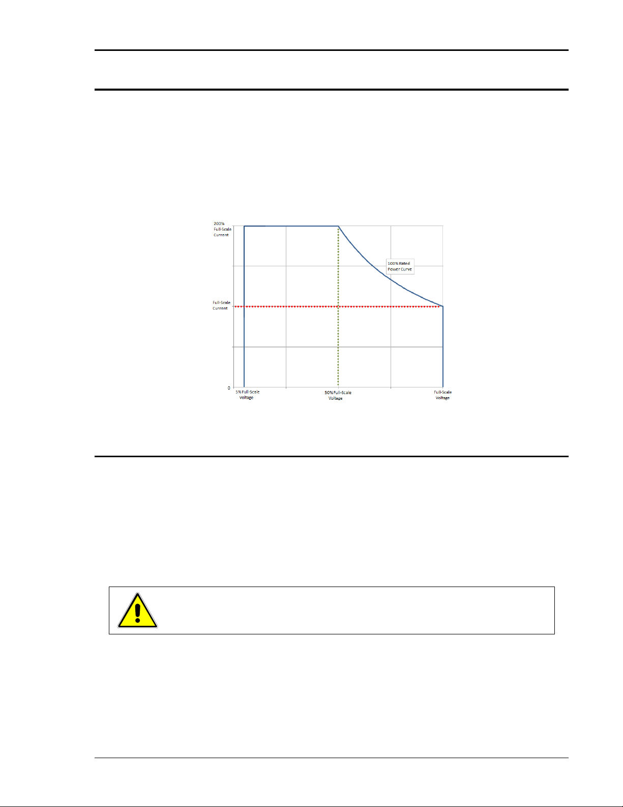
Asterion Series User Manual – 1U Models California Instruments
M330000-01, REV-G 63
4.4 Output Power Characteristic
The iX2TM Constant-Power output characteristic of the Asterion power source has a power limit that is
present in each of the two output voltage ranges (low-range and high-range) for AC and DC outputs. Full
rated output power is available from 100% of full-scale output voltage down to 50% of full-scale output
voltage; refer to Figure 4-4 for the relation between the voltage and current follows a constant-power
curve with the limit being the rated power of the unit: The output current increases to 200% of full-scale
output current as output voltage is reduced to 50% of full-scale output voltage. Accordingly, the power
source will automatically adjust the allowed maximum value of the programmed output current when the
output voltage is within 50% and 100% of full-scale to ensure that the power limit is not exceeded. Refer
to graphs for current rating as a function of output voltage and frequency in Figure 2-1 and Figure 2-2.
Figure 4-4. iX2TM Constant-Power Output Characteristic
4.4.1 Front Panel Touch-Screen Display
The front panel display of the Asterion Series power source allows the user to select the various menus
required to configure and operate the unit. Navigating through the various menus could be done using
the touch-screen display or the rotary encoder. Tapping the display screen or clicking with the encoder
on any menu or function that is highlighted (active) will enter that menu or execute that function.
The touch-screen utilizes resistive, pressure-actuated technology, and depends on pressure being
applied to the top surface of the screen to detect the position of input. A fingertip, fingernail, or stylus pen
could be used. To prevent scratching the surface layer, do not use a hard or sharp tip, such as ball-point
pen or mechanical pencil.
.
CAUTION!
Damage or scratching of the touch-screen could occur if excessive pressure is
applied to the surface, or if objects with hard/sharp tips are used.
Page 64

Asterion Series User Manual – 1U Models California Instruments
64 M330000-01, REV-G
The present cursor position is always shown with a selection-box that has a highlighted border around a
field. Some screens have multiple pages, as indicated by the highlighted Arrow icons located on the right
side of the screen: for example, the default HOME Screen can be scrolled through three pages.
Tapping an Arrow, or selecting it with the rotary encoder and clicking the switch, scrolls the screen to the
next page. When outside one of the HOME screens, tapping the Home icon will exit that screen and
return back to the HOME screens. Refer to Figure 4-5 and Figure 4-12.
Figure 4-5. HOME Screen
Parameters that are adjustable have selection-fields where values could be entered. The parameter
selection-field that is active has its border highlighted; refer to Figure 4-6 where the Dashboard Menu is
shown with the voltage selection-field active. Tapping the selection-field box, selects that parameter for
adjustment, and the screen changes to the numeric keypad that allows value entry; refer to Figure 4-7.
Figure 4-6. DASHBOARD Screen Menu with Voltage Selection-Field Active
4.4.2 Touch-Screen Numeric Keypad
The touch-screen has a keypad that allows numeric value entry; refer to Figure 4-7. After scrolling
through menus until a parameter selection-field box is highlighted (active), tapping the selection-field
selects it. Afterwards, the keypad screen will be displayed. Tapping numerical value keys, the decimal
point key, or the polarity key, selects them, while the back-arrow key erases the last entry. To enter a
negative value, first enter the number then the minus sign. The selected values appear in the upper-left
parameter window, and the cursor moves to the next available position. Tapping the OK key enters the
value to have it take effect.
Figure 4-7. Touch-Screen Numeric Keypad
4.4.3 Rotary Encoder
The rotary encoder provides a secondary way to navigate the display. It is used to select functions,
change parameter values, and perform setup. It can be used to move between menu screens and
between editable items within an individual menu screen.
The rotary encoder is located on the front panel and provides continuous adjustment in the clockwise
and counter-clockwise rotation; refer to Figure 4-8. Turning the encoder knob allows sequential scrolling
Page 65

Asterion Series User Manual – 1U Models California Instruments
M330000-01, REV-G 65
through each menu or function on a screen; the item that is active has its selection field-box highlighted.
To select a choice, depress the encoder knob to engage the encoder momentary switch.
Figure 4-8. Rotary Encoder
The rotary encoder can operate in one of two distinct modes:
MODE DESCRIPTION
NAVIGATE The rotary encoder can be used to scroll through menu screen
functions and settings. The current (active) selected item will be
outlined in a highlighted selection-field box. As the encoder is
rotated, the highlighted box will be scrolled through all items on a
screen that could be selected; refer to Figure 4-9.
ADJUST/SELECT After scrolling to a function, the rotary encoder knob is depressed to
select the function (clicking on an item). Clicking on a
selection-button will change its state (on or off), and clicking on a
function or menu will select it and change to a screen that allows
further value entry.
Parameter values, such as voltage and current, are adjusted by
selecting the parameter (clicking on it) to enable the selection-field
(refer to Figure 4-9). If a parameter had been selected whose value
could be adjusted, and the encoder switch is depressed, a screen
will be displayed with a parameter selection-field highlighted that has
a value entry window (refer to Figure 4-10). The rotary encoder could
then be used to continuously adjust the parameter value, up and
down, as the encoder is rotated. Click the encoder a second time to
enter the value. If the OUTPUT switch is on, the output parameter
will change when the encoder is clicked.
The DASHBOARD screen menu has the capability for real-time
adjustment of output parameters: the value of the parameters
change as the rotary encoder is turned for immediate effect at the
output. If the OUTPUT switch is on, the output parameter will change
as the encoder is rotated. Refer to the DASHBOARD screen menu in
Section 4.6.1 for a description of the parameters that have real-time
adjustability.
Page 66

Asterion Series User Manual – 1U Models California Instruments
66 M330000-01, REV-G
Figure 4-9. Output Program Menu Selection-Fields with Voltage Highlighted
Figure 4-10. Highlighted Voltage Selection-Field with Value Window
The rotary encoder could also be used with the numeric keypad to
enter values. After selecting a parameter using the touch-screen, the
numeric keypad will be displayed; refer to Figure 4-7. The rotary
encoder could be used to select any of the items of the numeric
keypad by scrolling through them and clicking on them with the
encoder switch to select them. The active value is identified on the
screen with a highlighted field-box, and the entered decimal places
are shown in the upper-left window. The cursor moves to the next
available position as values are entered. After the desired decimal
places are entered sequentially, the OK key is clicked to execute the
final value and have it take effect.
Page 67

Asterion Series User Manual – 1U Models California Instruments
M330000-01, REV-G 67
4.5 Menu Structure
The front panel menu structure is comprised of three home screens, and up to seven levels of menus
and sub-menus. The following menu map provides the logical structure of the menus.
HOME Screen-1,
Level-1
Level-2 Level-3
Level-4
DASHBOARD
DASHBOARD
DEFAULT SCREEN
OUTPUT
VOLTAGE
SET VOLTAGE
PROGRAM
CURRENT
SET CURRENT
VOLTAGE RANGE
SET VOLTAGE RANGE
FREQUENCY
SET FREQUENCY
DC OFFSET
SET DC OFFSET
AC/DC
SET AC/DC
PHASE
SET PHASE
OVP SET OVP
REGULATION
SET REGULATION
WAVEFORM
SET WAVEFORM
TIME DOMAIN
HARMONIC ANALYSIS
MEASUREMENTS
GROUP MEASURE.
READ GROUP MEASURE.
VOLTAGE
READ VOLTAGE
FREQUENCY
READ FREQUENCY
CURRENT
READ CURRENT
POWER
READ POWER
PHASE
READ PHASE
POWER FACTOR
READ POWER FACTOR
CREST FACTOR
READ CREST FACTOR
WATT-HOUR
READ WATT-HOUR
CURRENT THD
READ CURRENT THD
VOLTAGE THD
READ VOLTAGE THD
HARMONICS
VIEW TABLE
BAR GRAPH
TRACE CAPTURE
TRACE
ZOOM VIEW
DEFAULT MEASURE.
READ DEFAULT SCREEN
Table 4-3. HOME Screen-1 Menu Structure
Page 68

Asterion Series User Manual – 1U Models California Instruments
68 M330000-01, REV-G
HOME Screen-2,
Level-1
Level-2
Level-3
Level-4 Level-5
TRANSIENTS
SETTINGS
TRIGGER
VIEW EMPTY BUFFER/
ADD VOLTAGE DROP
LIST ENTRY
VOLTAGE SWEEP/STEP
VOLTAGE SURGE/SAG
LIST ENTRY
FREQUENCY SWEEP/STEP
FREQUENCY SURGE/SAG
VOLT/FREQ SWEEP/STEP
VOLT/FREQ SURGE/SAG
DELAY RUN REPEAT
X TIMES
CONTROL
ANALOG
SET ANALOG
RS232
SET RS232
GPIB SET GPIB
LAN LAN SETTINGS
READ LAN
SETTINGS
LAN CONFIGURE
SET IP ADDRESS
SET SUBNET
MASK
SET GATEWAY
ADDRESS
SET PORT
NUMBER
READ MAC
ADDRESS
SET HOST NAME
SET LAN CONFIG
RESTORE
DEFAULT
REMOTE INHIBIT
SET REMOTE
INHIBIT
Table 4-4. Home Screen-2 Menu Structure
Page 69

Asterion Series User Manual – 1U Models California Instruments
M330000-01, REV-G 69
HOME Screen-2
Level-1,
(continued)
Level-2 Level-3
Level-4
Level-5
CONFIGURATION
OUTPUT SENSE
SET OUTPUT SENSE
PONS
VOLTAGE
SET VOLTAGE
VOLTAGE MODE
SET VOLTAGE MODE
VOLTAGE RANGE
SET VOLTAGE RANGE
CURRENT
SET CURRENT
FREQUENCY
SET FREQUENCY
PHASE
SET PHASE
CURRENT MODE
SET CURRENT MODE
VOLTAGE SENSE
SET VOLTAGE SENSE
WAVEFORM
SET WAVEFORM
TIME DOMAIN
HARMONIC ANALYSIS
OUTPUT
SET OUTPUT
CLOCK CONFIG
SET CLOCK CONFIG
ALC SET ALC
REFERENCE
SET REFERENCE
PROFILES
SET PROFILES
NAME
USER V-LIMIT
SET USER V-LIMIT
USER F-LIMIT
SET USER F-LIMIT
DEFAULT
SCREEN
SET DEFAULT
SCREEN
XLOAD
SET XLOAD
Table 4-5. HOME Screen-2 Menu Structure (continued)
Page 70

Asterion Series User Manual – 1U Models California Instruments
70 M330000-01, REV-G
HOME Screen-3,
Level-1
Level-2
Level-3
Level-3
APPLICATIONS
APPLICATIONS
OPTION
SET APPLICATIONS
OPTIONS
SYSTEM
SETTINGS
FIRMWARE VERSION
READ FIRMWARE
VERSION
OPTIONS
READ OPTIONS
LANGUAGE
SET LANGUAGE
HARDWARE LIMITS
READ HARDWARE
LIMITS
LCD SET LCD
SET BRIGHTNESS
SET CALIBRATION
Table 4-6. HOME Screen-3 Menu Structure
4.6 Front Panel Display Menus
At initial power-on, the display shows the Asterion Splash screen followed by the Start-Up screen with
the model number, serial number and firmware revisions, and finally the Default screen showing output
voltage and current values. Refer to Figure 4-11.
Figure 4-11. Power-On Screens
Page 71

Asterion Series User Manual – 1U Models California Instruments
M330000-01, REV-G 71
Selecting the Home icon or Up arrow will open the HOME screen of the menu structure. It is made up of
three pages: Screen-1 through Screen-3, as shown in Figure 4-12. The three pages have menus, as
follows:
HOME Screen-1: DASHBOARD, OUTPUT PROGRAM, and MEASUREMENTS;
HOME Screen-2: TRANSIENTS, CONFIGURATION, and CONTROL INTERFACE;
HOME Screen-3: APPLICATIONS and SYSTEM SETTINGS.
Each menu of a screen could be selected by tapping its associated selection-field box through the
touch-screen, or by selecting it with the rotary encoder and depressing (clicking) the rotary encoder
SELECT switch.
HOME Screen-1
HOME Screen-2
HOME Screen-3
Figure 4-12. HOME Screen Pages
There are four virtual buttons visible on a screen: UP, LEFT, and RIGHT arrows, and HOME icon. Those
buttons that are highlighted are active for the particular screen being displayed. The arrow buttons will
scroll to the next page of the menu structure in the direction indicated. The HOME button will return to
the previous home screen that has the top-level menu from which a sub-menu was entered. The HOME
button is no longer functional once a home screen is entered.
Page 72

Asterion Series User Manual – 1U Models California Instruments
72 M330000-01, REV-G
The following top-level menu choices can be accessed through the touch-screen:
Home Screen
Top-Level Screen Menu
Menu Description
Screen-1
DASHBOARD
Provides setting and measurement of output parameters:
voltage, current, frequency, and voltage range. Provides
automatic transition to Default screen.
OUTPUT PROGRAM
Provides setting of output mode of operation, individual
output parameters, mode of regulation, current limit,
OVP, and output waveform selection
MEASUREMENTS
Provides measurement of output parameters and
harmonic distortion, advanced harmonics analysis,
selection of Default measurements, and real-time display
output waveform; no user settings are available.
Screen-2
TRANSIENTS
Provides setup, running, and saving of output transient
lists.
CONFIGURATION
Provides setup of power-on states, operation profiles,
parameter limits, and selection of clock configuration and
mode, Default screen, and XLOAD.
CONTROL INTERFACE
Provides setup of remote analog and digital interfaces,
and Remote Inhibit.
Screen-3
APPLICATIONS
Provides selection and setup of application-specific
options that are installed in the unit.
SYSTEM SETTINGS
Provides display of firmware versions, software options
that are installed in the unit; hardware parameter limits,
selection of language and brightness for the display, and
touch-screen calibration.
Table 4-7. HOME Screen-1, Screen-2, Screen-3 Menu Content
Page 73

Asterion Series User Manual – 1U Models California Instruments
M330000-01, REV-G 73
4.6.1 DASHBOARD Screen Top-Level Menu
The DASHBOARD screen top-level menu is used to change output parameters and simultaneously view
output measurements. The most commonly used output parameters are located in the DASHBOARD
screen menu. The DASHBOARD screen is the default menu that is displayed after power-on.
The top-level menu of the DASHBOARD screen is shown in Figure 4-13. It can be reached in one of two
ways:
1. Tapping DASHBOARD on Home Screen-1 of the front panel touch-screen;
2. Scrolling to DASHBOARD with the encoder and depressing the encoder switch.
The UP arrow button will return back to the previously selected screen menu (in this case the
Home Screen-1). The HOME button will return back to the home screen that has the top-level menu for
the sub-menu being displayed; for the DASHBOARD screen top-level menu, that is the HOME Screen-1.
Figure 4-13. DASHBORD Screen Top-Level Menu
The following selections are available in the DASHBOARD screen top-level menu. Functions that accept
a numeric value require that the value is within the allowed range, otherwise, an error will be generated,
and the value will not be accepted.
Entry Description
Settings
VOLTAGE Programs the output voltage in RMS value, V(RMS), when in
AC-mode and DC-mode, and the AC component when in
(AC+DC)-mode. In (AC+DC)-mode, the DC component is
programmed using the DC OFFSET sub-menu in the OUTPUT
PROGRAM menu. In DC mode, negative values can also be
entered. Real-time setting is possible using the rotary encoder; refer
to Section 4.6.1.1.
CURRENT Programs the output current in RMS value, A(RMS). Real-time
setting is possible using the rotary encoder; refer to Section 4.6.1.1.
FREQUENCY Programs the output frequency in Hz when in AC-mode. If the unit is
in DC-mode, the value for FREQ will be set to DC and cannot be
changed until AC-mode is selected. When in AC-mode, the
frequency can be changed from 16 Hz to 5000 Hz (depending on
options). Real-time setting is possible using the rotary encoder; refer
to Section 4.6.1.1.
VOLTAGE RANGE Selects the 200 VAC or 400 VAC range for AC-mode and
(AC+DC)-mode, and 250 VDC or 500 VDC range for DC-mode
operation. The OUTPUT state must be OFF for a change in range to
be executed.
Page 74
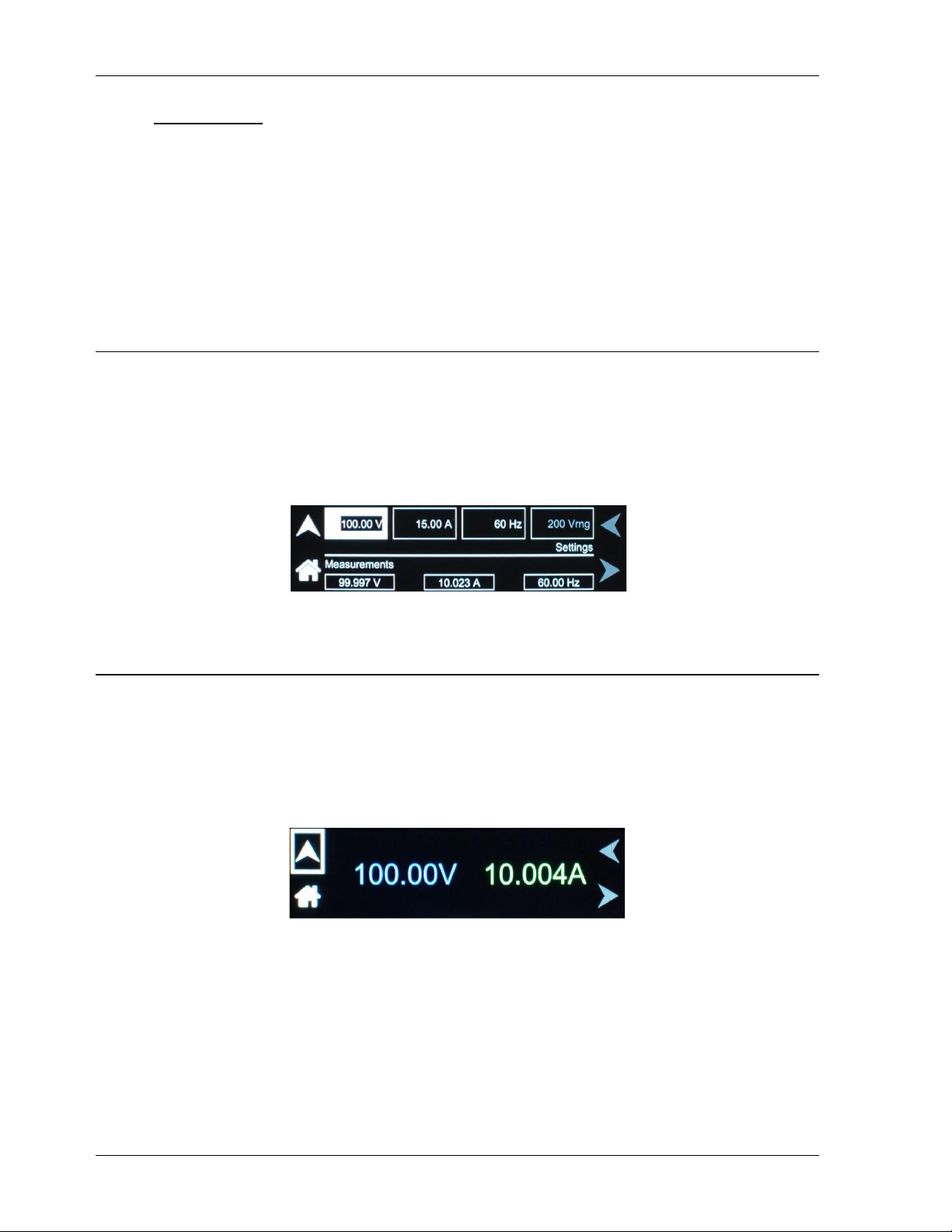
Asterion Series User Manual – 1U Models California Instruments
74 M330000-01, REV-G
Measurements
VOLTAGE Displays the true RMS value of the output voltage measured at the
voltage sense lines (user selectable to be local or remote). In
DC-mode only, the voltage is the DC voltage including polarity.
CURRENT Displays the true RMS value of the output current. In DC-mode only,
the current is the DC current including polarity.
FREQUENCY When in AC-mode or (AC+DC)-mode, the output frequency is
measured at the sense lines. When in DC-mode, this value always
reads “DC”.
4.6.1.1 Real-Time Parameter Adjustment
The DASHBOARD screen menu provides the capability for output parameter entry that has real-time,
immediate effect on the output. This allows manual adjustment of the output parameters where tuning of
a value is desired. Enabling this function requires clicking on a parameter selection-field box with the
encoder switch to select the parameter and display its selection-field highlighted and with a value entry
window (refer to Figure 4-14). The rotary encoder could then be used to continuously adjust the
parameter value, up and down, as it is rotated. The value change takes immediate effect at the output.
Figure 4-14. Real-Time, Immediate Output Parameter Adjustment
4.6.1.2 Default Screen
The Default screen provides measurement of the RMS output voltage and current; refer to Figure 4-15.
Initially, it appears after power-on if it has been enabled to do so in the configuration setup (user
selectable; refer to Section 4.6.5). Subsequently, when in the Dashboard screen, and idle for an interval
equal to a set time delay, the display will automatically switch to the Default screen. The Default screen
could also be selected from the MEASUREMENTS screen; refer to Figure 4-17. Tap anywhere on the
screen, including the Up arrow, to return to the Dashboard screen; tap the Home icon to return to the
HOME Screen-1. Refer to Section 4.6.5 for setup of the Default screen.
Figure 4-15. Default Screen
Page 75

Asterion Series User Manual – 1U Models California Instruments
M330000-01, REV-G 75
4.6.2 OUTPUT PROGRAM Screen Top Level Menus
The OUTPUT PROGRAM screen provides setting of output related items such as individual output
parameters, mode of regulation and current limit, output waveform selection, and display of real-time
output waveform or harmonics spectrum.
The top-level menus of the OUTPUT PROGRAM screen are shown in Figure 4-16. They could be
reached in one of two ways:
1. Tapping the OUTPUT PROGRAM screen on Home Screen-1 of the front panel touch-screen;
2. Scrolling to the OUTPUT PROGRAM screen with the encoder and depressing the encoder
switch.
The UP arrow button will return back to the previously selected screen menu (in this case the
HOME Screen-1). The HOME button will return back to the home screen that has the top-level menu for
the sub-menu being displayed; for the OUTPUT PROGRAM screen top-level menu, that is the
HOME Screen-1.
Top-Level Menu-1
Top-Level Menu-2
Figure 4-16. OUTPUT PROGRAM Screen Top-Level Menu-1/2
The following choices are available in the OUTPUT PROGRAM screen top-level menu. Functions that
accept a numeric value require that the value is within the allowed range, otherwise, an error will be
generated, and the value will not be accepted.:
Entry Description
Settings
VOLTAGE Programs the output voltage in RMS value, V(RMS), when in
AC-mode and DC-mode, and the AC component when in
(AC+DC)-mode. In (AC+DC)-mode, the DC component is set
separately using the DC OFFSET selection-field (below), or through
the Dashboard screen. In DC-mode, negative values can also be
entered. The default is zero.
Page 76

Asterion Series User Manual – 1U Models California Instruments
76 M330000-01, REV-G
CURRENT Programs the output current in RMS value, A(RMS). The default is
full-scale for the model.
VOLTAGE RANGE Selects the 200 VAC or 400 VAC range for AC-mode and
(AC+DC)-mode, and 250 VDC or 500 VDC range for DC-mode
operation. The output must be turned off for a change in range to be
executed. The default is low-range, 200 VAC.
FREQUENCY Programs the output frequency in Hz when in AC-mode. If the unit is
in DC-mode, the value for FREQ will be set to DC and cannot be
changed until AC-mode is selected. When in AC-mode, the
frequency can be changed from 16 Hz to 5000 Hz (depending on
options). The default is 60 Hz.
DC OFFSET Programs the DC offset value, V(DC), when in the (AC+DC)-mode;
entries with positive and negative polarity are allowed. The AC
component of the output voltage is set separately using the
VOLTAGE selection-field (above) or through the Dashboard screen.
In AC-mode and DC-mode, this function is not available, and the
function is listed as “N/A”. The default is zero.
AC/DC Selects the mode of operation of output voltage: either AC only, DC
only, or AC with a DC offset, AC+DC. This selection also determines
the available output voltage ranges: 200/400 V(RMS) in AC and
AC+DC modes, and 250/500 VDC in DC mode. The output must be
turned off to change this setting. The default is AC.
Page 77

Asterion Series User Manual – 1U Models California Instruments
M330000-01, REV-G 77
OVP Programs the Overvoltage Protection (OVP) threshold for the output
voltage. Exceeding the OVP threshold will result in shutdown of the
output, with the output isolation relay opened and the output voltage
programmed to zero. The maximum OVP setpoint is 115% of
full-scale low-range/high-range output voltage: AC-Mode and
(AC+DC)-mode, 230V/430V; DC-Mode, 287.5V/575V. The default
value is 115% of full-scale.
PHASE Programs the phase angle of the output voltage: in a standalone
unit, the phase angle would be with respect to the external SYNC
signal; in an Auxiliary unit (with LKS option) of a multi-phase group,
the phase angle would be with respect to Phase-A, while Phase-A
would be the reference at 0°. If the clock source is selected to be
internal, this parameter has no effect. The default is zero.
WAVEFORM Selects the waveform for the output voltage: either standard
waveforms for sine wave, square wave, or clipped-sine wave; or,
user-defined waveforms. The default is sine wave.
The standard waveforms are always available, and do not consume
any of the user-defined waveform memory registers; they are always
displayed in the waveform list. The clipped-sine waveform has a
waveform where the peak amplitude of the positive and negative
alternation is clipped (flattened appearance). The level of clipping is
dependent on the amount of harmonic distortion present in the
output waveform. An additional programmable parameter,
CLIP % THD, is available for setting the percentage of total
harmonic distortion (THD); the range is 0-43%.
The user-defined waveforms could be selected from up to fifty
waveforms in one of four groups (group 0-3, totaling 200 waveforms)
that are active. The waveform group that is active at power-on of the
unit could be selected with the SCPI command,
PONSetup:WGRoup <n>, through the digital interface. For
information on generating user-defined waveforms and their
selection, refer to the Asterion Virtual Panels or the Asterion Series
Programming Manual P/N M330100-01 (distributed on the CD,
CIC496), or refer to the AMETEK Programmable Power website,
www.powerandtest.com, to download latest versions.
Page 78
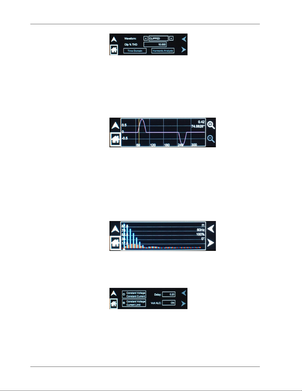
Asterion Series User Manual – 1U Models California Instruments
78 M330000-01, REV-G
Time Domain selection-field: This function displays the voltage
waveform in the time domain (oscilloscope function). This function is
active for user-defined waveforms, but not for standard waveforms.
The units of the horizontal axis are in degrees and of the vertical axis
in fraction of full-scale value. The waveform is scaled to fit the
viewing area. The upper right-side corner shows parameter data
(fraction of full-scale and phase angle) of the point on the waveform
selected by the yellow cursor. A zoom function is available to
observe the waveform in more detail. Refer to Section 6.2.3 for
detailed information on using the cursor and zoom function.
Harmonic Analysis selection-field: This function displays the
frequency spectrum of the voltage waveform derived through FFT
(fast Fourier transform) analysis. This function is active for
user-defined waveforms, but not for standard waveforms. The
frequency spectrum is displayed in graphical format, ranging from
DC through the 50th harmonic. Individual harmonics could be
selected (shown with triangle along horizontal axis) to display their
parameter data using the Right and Left arrow buttons, touchscreen, or encoder. The upper right-side presents the data for the
selected harmonic: harmonic number, frequency, percentage of
fundamental, and phase angle).
REGULATION Selects options for regulation of the output voltage: whether ALC is
enabled, and what control action will be performed when the load
current reaches the current setpoint. The defaults are CV/CL, with
Delay of 0.2 seconds and ALC on.
Page 79

Asterion Series User Manual – 1U Models California Instruments
M330000-01, REV-G 79
Constant-Voltage/Constant-Current (CV/CC): CV/CC mode will
regulate the output voltage to the set value until the load current
reaches the current setpoint; after the Delay interval, if the current
exceeds the setpoint, the output current will be controlled to equal
the setpoint. Regulation of the load current is accomplished by
reducing the output voltage as needed to satisfy the load. As such,
the voltage could be reduced from the set value down to zero,
depending on the load requirement. This mode is useful for starting
up motor or capacitor loads that may require a high inrush current.
In constant-voltage mode of operation, the waveform and
instantaneous amplitude of the output voltage is regulated to equal
the programmed values; if Volt ALC is enabled, the RMS value is
also precisely regulated. In constant-current mode of operation, the
RMS value of the output current is regulated to equal the
programmed value. However, this is accomplished by controlling the
voltage amplitude and waveform, and not directly the current;
therefore, the current instantaneous amplitude and waveform and
dependent on load characteristics.
Constant-Voltage/Current-Limit (CV/CL): CV/CL mode will
regulate the output voltage to the set value until the load current
reaches the current setpoint; after the Delay interval, if the current
equals or exceeds the setpoint, a fault condition will be generated,
and the output voltage will be programmed to zero and the isolation
relay opened. This effectively turns off the AC source output in case
of an overload condition, after the user-programmable trip
time-delay.
Delay: Sets the time duration that the output current could equal or
exceed the current setpoint before control action is taken. After the
delay, if CV/CC mode is selected, the output current will be
regulated to its setpoint; if CV/CL mode is selected, an overcurrent
fault condition will be generated and the output will be turned off.
The Delay is programmable from 0.1-5 seconds.
Volt ALC: Volt ALC selects whether the automatic loop control,
ALC, is enabled. ALC provides improved output regulation and
accuracy by regulating the RMS value of the output voltage through
action of a digital regulator that measures the output voltage and
controls it to equal the setpoint.
ON: ALC is enabled; regulation is accomplished through the
RMS digital regulator; if the RMS digital regulator exceeds its
control capability and could not maintain regulation, the output
will be shut down and a fault condition will be generated with
the output turned off and the voltage programmed to zero;
REG: ALC is enabled; regulation is accomplished through the
RMS digital regulator; if the RMS digital regulator exceeds its
control capability and could not maintain regulation, the output
will remain on, but the voltage will deviate from the setpoint,
and a fault condition will not be generated;
OFF: ALC disabled; regulation is accomplished without use of
the RMS digital regulator, and shutdown that is dependent on
loss of regulation will not occur.
Page 80

Asterion Series User Manual – 1U Models California Instruments
80 M330000-01, REV-G
4.6.3 MEASUREMENTS Screen Top-Level Menus
The Asterion Series power source uses a DSP-based data acquisition system to provide extensive
information regarding the output parameters. This data acquisition system digitizes the voltage and
current waveforms and calculates parameter values from the data. The result of these calculations is
displayed in a series of measurement data screens. The actual digitized waveforms can also be
displayed by selecting the Trace Capture screen. The MEASUREMENTS screen top-level menu is used
to display the results of output parameter measurements, harmonics analysis, and output waveforms.
The top-level menus of the MEASUREMENTS screens are shown in Figure 4-17. They can be reached
in one of two ways:
1. Tapping MEASUREMENTS on Home Screen-1 of the front panel touch-screen;
2. Scrolling to MEASUREMENTS with the encoder and depressing the encoder switch.
The UP arrow button will return back to the previously selected screen menu (in this case the
Home Screen-1). The HOME button will return back to the home screen that has the top-level menu for
the sub-menu being displayed; for the MEASUREMENTS screen top-level menus, that is the
HOME Screen-1.
Top-Level Menu-1
Top-Level Menu-2
Top-Level Menu-3
Figure 4-17. MEASUREMENTS Screen Top-Level Menu-1/2/3
Page 81

Asterion Series User Manual – 1U Models California Instruments
M330000-01, REV-G 81
The following functions are available in the menus of the MEASUREMENTS screen:
Entry Description
GROUP MEASUREMENTS Displays the following output parameters together on one screen:
RMS voltage, RMS current, frequency, real power, apparent
power, and power factor
.
FREQUENCY When in AC-mode or (AC+DC)-mode, displays the output
frequency. In the DC-mode, this value always reads “DC”.
POWER Displays the true power, kW, and apparent power, kVA, of the
load.
VOLTAGE Displays the true RMS value of the output voltage measured at
the voltage sense lines (user selectable to be local or remote). In
DC-mode only, the voltage is the DC voltage including polarity.
CURRENT When in AC-mode or (AC+DC)-mode, displays the RMS output
current. In the DC-mode, displays the DC current including
polarity. The Peak Current displayed is the maximum
instantaneous value that has been detected. The Reset function
allows resetting the peak value to zero and restarting current
tracking. The peak current measurement will continuously track
the maximum current value detected until reset.
Page 82

Asterion Series User Manual – 1U Models California Instruments
82 M330000-01, REV-G
PHASE Displays the phase angle of the output of the power source: in a
standalone unit, the phase angle would be with respect to the
external SYNC signal; in an Auxiliary unit (with LKS option) of a
multi-phase group, the phase angle would be between the Auxiliary
output and the Master output. If the clock source is selected to be
internal, this parameter is not used.
POWER FACTOR Displays the power factor of the load.
WATT HOUR Displays the energy, kWh, consumed by the load, and the true
power in kW. The Start and Stop function determine the interval
during which energy is calculated. The Clear function resets the
accumulated energy value.
VOLTAGE THD Displays the total distortion of the output voltage. The distortion
calculation is based on the harmonics voltages, H2 through H50,
relative to the total RMS value of the voltage. Another common
definition of THD calculates the harmonics relative to the value of the
fundamental voltage H1. There might be a difference in results
depending on the harmonic content. The method is selectable over
the digital interface with the SCPI command, MEAS:THD:MODE
<value>, with the value being either RMS (relative to total RMS) or
FUND (relative to fundamental).
CREST FACTOR Displays the crest factor of the output current as the ratio of its peak
value to its RMS value.
Page 83

Asterion Series User Manual – 1U Models California Instruments
M330000-01, REV-G 83
CURRENT THD Displays the total distortion of the output current. The distortion
calculation is based on the harmonics currents, H2 through H50,
relative to the total RMS value of the current. Another common
definition of THD calculates the harmonics relative to the value of the
fundamental current H1. There might be a difference in results
depending on the harmonic content. The method is selectable over
the digital interface with the SCPI command, MEAS:THD:MODE
<value>, with the value being either RMS (relative to total RMS) or
FUND (relative to fundamental).
HARMONICS Displays harmonic content of voltage and current waveforms derived
from an FFT analysis. The amplitude and phase of harmonics up to
the 50th (bandwidth limited) are calculated and displayed.
Figure 4-18. HARMONICS Menu
The HARMONICS menu has the following fields:
Entry Description
FUNCTION HARMONICS menu: Selects Voltage or Current for display.
VIEW HARMONICS menu: Selects display modes, as follows:
Table: Displays the first 50 harmonics (bandwidth limited) in a
tabular text format, shown below;
Bar: Displays the first 50 harmonics (bandwidth limited) in a
graphical bar chart display, shown below.
DATA HARMONICS menu: Selects absolute or relative harmonics
display for TABLE and BAR view modes. In relative mode, all
harmonics are shown in a percentage of the fundamental which
is normalized at 100%. In absolute mode, the harmonic
amplitudes are shown in absolute volts or amperes.
Page 84

Asterion Series User Manual – 1U Models California Instruments
84 M330000-01, REV-G
MODE HARMONICS menu: Selects the trigger mode for the
acquisition, as follows:
SINGLE: Single-shot acquisition; in this mode, the acquisition is
triggered once each time the START field is selected. The
selected trigger source is used to determine the trigger point.
Once the acquisition has been triggered, the data are displayed
and do not change until the next acquisition is triggered. This
mode is most appropriate for single-shot events, such as
startup currents.
CONTINUE: Continuous acquisition; in this mode, acquisitions
occur repeatedly and the data is updated on screen after each
trigger occurrence. This provides a continuous update of the
data, and is most appropriate for repetitive signals.
SOURCE HARMONICS menu: Selects the event that will trigger a
measurement acquisition, as follows;
IMMEDIATE: Causes the acquisition to trigger immediately
when the START field is selected. This is an asynchronous
trigger event. The acquisition will always be triggered in this
mode and data is available immediately.
PHASE: Causes the acquisition to trigger on the occurrence of
zero phase angle of the output voltage. When started, the
acquisition holds until the zero phase angle occurs, before
triggering the acquisition. This mode allows exact positioning of
the acquisition data window with respect to the voltage
waveform.
DELAY HARMONICS menu: Selects the time delay to position the
trigger point relative to the acquisition window. A negative value
will provide pre-trigger information on data leading up to the
trigger event. The pre-trigger delay cannot exceed the length of
the acquisition buffer; see Section 6.4.3 for details. A positive
trigger delay positions the data window after the trigger event.
Positive trigger delays can exceed the length of the acquisition
buffer in which case the trigger event itself will not be in the
buffer any more. The maximum value of the trigger delay is
1000 ms. The default trigger delay value is 0.0 ms which puts
the trigger event at the beginning of the acquisition window.
START HARMONICS menu: Starts a new acquisition run. When the
start field is selected, and after the trigger event occurs, the
display changes to the data display mode that was selected in
the VIEW field of the HARMONICS menu; refer to Figure 4-18.
To return to the HARMONICS menu, tap the HOME button
while in the data display screen.
Page 85

Asterion Series User Manual – 1U Models California Instruments
M330000-01, REV-G 85
Harmonics Table View: This function displays the frequency spectrum of the output voltage
or current waveform (selected by Function selection-field) derived
through FFT (fast Fourier transform) analysis. The frequency
spectrum is listed in tabular format, ranging from the fundamental
through the 50th harmonic, in five groups of ten harmonics. The
groups are selected through use of the Right and Left arrow buttons.
Each harmonic has the following parameter data: harmonic number,
amplitude, and phase angle. Refer to Section 6.2.2 for additional
information on the harmonics tabular view.
Figure 4-19. HARMONICS Menu, Table View
Harmonics Bar View: This function displays the frequency spectrum of the output voltage
or current waveform derived through FFT (fast Fourier transform)
analysis. The frequency spectrum is displayed in graphical format,
ranging from DC through the 49th harmonic; up to 25 harmonic
components are shown per screen. Individual harmonics could be
selected (shown with triangle along horizontal axis) to display their
parameter data using the Right and Left arrow buttons,
touch-screen, or encoder. The upper right-side presents the data for
the selected harmonic: harmonic number, frequency, percentage of
fundamental, and phase angle). Refer to Section 6.2.2 for additional
information on the harmonics graphical view.
Figure 4-20. HARMONICS Menu, Bar Graph View
Page 86

Asterion Series User Manual – 1U Models California Instruments
86 M330000-01, REV-G
TRACE CAPTURE Displays the real-time waveform (oscilloscope function) of the output
voltage. A cursor (yellow color) is available to select the position on
the waveform where the instantaneous value of the voltage, along
with the time, would be displayed in the right-side, upper corner;
refer to Figure 4-21, where the cursor has been moved from its initial
position at the left axis. The cursor position could be selected with
either the rotary encoder or touch-screen.
Using the encoder, first select the waveform window, and then click
the encoder switch to enter the window and activate the yellow
cursor; rotate the encoder to move the cursor to the desired position.
Click a second time to exit the waveform window.
Using the touch-screen, first select the waveform window, and then
tap at the desired position.
Figure 4-21. TRACE CAPTURE Screen
Zoom View: Selecting the Plus-Magnifier allows the display to be
zoomed to show an expanded view of the waveform; when active,
the Plus-Magnifier will be lit up. The section of the waveform to be
zoomed could be selected with either the rotary encoder or the
touch-screen.
Using the encoder, click on the Plus-Magnifier to active it, then rotate
the encoder to select the waveform window. Click again to show the
zoom cursors; refer to Figure 4-22. Rotate the encoder to move the
cursors to the beginning of the waveform section to be expanded;
click the encoder to set the first cursor. Rotate the encoder to move
a second cursor to the end of the section; click again to display the
expanded section. Double-arrows in the right-side, upper corner
indicate the direction from the expanded trace to the yellow cursor
position.
Figure 4-22. TRACE Screen, Plus-Magnifier and Zoom Cursors
Using the touch-screen, tap the Plus-Magnifier to active it, then tap
the waveform window to select it. Touch on the beginning of the
waveform section to be expanded, and while continuing to touch the
screen, move to the ending position; no longer touching the screen
will display the expanded section. Double-arrows in the right-side,
upper corner indicate the direction from the expanded trace to the
yellow cursor position.
Page 87

Asterion Series User Manual – 1U Models California Instruments
M330000-01, REV-G 87
Multiple levels of zoom could be executed. When the display is
showing an expanded section, the Minus-Magnifier will be available;
refer to Figure 4-23. Tapping on it will cause the display to revert to
the previous level of zoom. The level of zoom could be reversed until
the original waveform is displayed.
Figure 4-23. TRACE Screen, Zoom View
DEFAULT Displays Default screen showing output voltage/current. Refer to
MEASUREMENTS Section 4.6.5 for setup of the Default screen.
4.6.4 TRANSIENTS Screen Top-Level Menu
The Asterion Series power source provides the capability of generating custom waveforms through
programming the output in a sequence of steps in a list of transients. The steps could be comprised of
combinations of changes in voltage, frequency, phase angle, waveform, and duration. The list could be
created, run and stored through either the front panel, or the remote digital interface using the Asterion
Virtual Panels program or SCPI commands. A library of lists could be produced and stored in memory of
the power source for quick recall and utilization through use of SCPI commands or the Asterion Virtual
Panels. Refer to the Asterion Series Programming Manual P/N M330100-01 (distributed on the CD,
CIC496), or refer to the AMETEK Programmable Power website, www.powerandtest.com, to download
latest versions.
The TRANSIENTS Screen provides access to the transient list data. A transient list of up to 100 data
points is possible, represented by 100 transient step numbers from 0 through 99.
The top-level menu of the TRANSIENTS screen is shown in Figure 4-24. It can be reached in one of two
ways:
1. Tapping TRANSIENTS on Home Screen-2 of the front panel touch-screen;
2. Scrolling to TRANSIENTS with the encoder and depressing the encoder switch.
The UP arrow button will return back to the previously selected screen menu (in this case the
Home Screen-1). The HOME button will return back to the home screen that has the top-level menu for
the sub-menu being displayed; that is HOME Screen-2 for the TRANSIENTS screen top-level menu.
Figure 4-24. TRANSIENTS Screen Top-Level Menu
Page 88

Asterion Series User Manual – 1U Models California Instruments
88 M330000-01, REV-G
The following menus are available in the TRANSIENTS top-level menu: SETTINGS, VIEW,
RUN.SETTINGS Menu
The SETTINGS menu allows selection of how parameter values are entered for time, voltage, and
frequency, trigger sources and characteristics, and how a list is executed; refer to Figure 4-25.
Figure 4-25. SETTINGS Menu
The SETTINGS menu has the following fields:
Entry Description
T(ime) Sets the units for time of the transient step; the default units are in
seconds. Alternately, the time could be changes to cycles of the
output frequency. Note that time durations in seconds may result in
rounding errors if the period of the programmed frequency is not an
integer number of milliseconds. For example, for 50 Hz output
(20 ms period), no rounding errors occur, but for 60Hz (16.66 ms
period) a rounding error would occur when converted. The time
duration scale selection affects both the Time and End Delay
parameters.
V(oltage) Sets the units for voltage values; the default units are in V(RMS). V
is the RMS value of the output voltage, while % is the percentage of
the steady-state setting.
F(requency) Sets the units for frequency values; the default units are in Hz. Hz is
the value of the output frequency, while % is the percentage of the
steady-state setting.
Start Phase Shows the start phase angle of the voltage transient in degrees.
Only one start phase angle per transient sequence is allowed. The
start phase angle must be in the first transient event of the list. The
start phase angle is not valid for DC transients.
Step Defines how the step sequence of the transient list is executed; the
default is All:
All: All of the steps in the sequence are executed without breaks;
Single: Each step is executed one at a time.
Page 89

Asterion Series User Manual – 1U Models California Instruments
M330000-01, REV-G 89
Trig(ger) The present state of the trigger settings is shown in the
TRIG field. Tap on the field to open the TRIGGER sub-menu
to change settings; refer to Figure 4-26.
Figure 4-26. SETTINGS Screen, TRIGGER Sub-Menu
The TRIGGER sub-menu has the following fields:
Entry Description
Phase Sync TRIGGER sub-menu: Determines when phase
synchronization is done; the default phase sync is All:
All: Synchronization is done at the beginning of the transient
list or pulse, for every count;
No(ne): Synchronization is done once at the beginning of the
transient list only for the first count.
Trig Out Source TRIGGER sub-menu: Selects the source for the trigger
output; the default source is BOT:
Bot: Beginning of transient output;
Eot: End of transient output;
List: At each point in the list (that has list-trigger enabled)
when that step is reached.
Start Source TRIGGER sub-menu: Determines the source of the trigger
event for the transient; the default source is IMM(ediate):
Imm(ediate): Triggering occurs as soon as the SCPI
command, INITiate, is received;
Bus: Triggering occurs following the SCPI command,
INITiate, after receiving the SCPI command, *TRG, or the
IEEE-488 Group Execute Trigger (GET) signal from the
GPIB interface;
Ext(ernal): Triggering occurs when an external trigger input
is received
Page 90

Asterion Series User Manual – 1U Models California Instruments
90 M330000-01, REV-G
4.6.4.1 VIEW Menu
The VIEW menu shows the transient list, with sequence numbers which are stored in the transient list
buffer. Figure 4-27 shows the menu when the buffer is empty, while Figure 4-28 shows the menu when
entries are present.
Figure 4-27. VIEW Menu, With Empty Buffer
Figure 4-28. VIEW Menu, With Transient List Entry
The VIEW menu has the following fields:
Entry Description
Add Allows generating a new transient list.
Before Inserts a step before the selected transient step
Edit Opens the selected step for editing parameters.
After Inserts a step after the selected transient step
Del Permanently deletes the selected transient step
Delete All Clears the transient list buffer
4.6.4.2 ADD Sub-Menu
The ADD sub-menu is opened when the ADD function is selected on the VIEW screen; refer to Figure
4-29. It allows selection of the type of transient to be added to the sequence.
Figure 4-29. VIEW Menu, ADD Sub-Menu
Page 91

Asterion Series User Manual – 1U Models California Instruments
M330000-01, REV-G 91
The ADD sub-menu has the following fields:
Entry Description
DROP Causes the output voltage to go to zero volts for a specified period of
time. As with the step transient, the voltage change is instantaneous.
At the end of the drop, the voltage will return to the amplitude at the
beginning of the step.
VOLTAGE SWEEP/STEP VOLTAGE SWEEP causes the output voltage to change from the
present value to a specified end value at a specified rate of change,
while a VOLTAGE STEP causes an instantaneous change in output
voltage. The new value will be held for the specified time duration.
The final output voltage value of a sweep and a step transient step
should be different than the value at the start of the transient step, or
no change in output voltage will occur.
VOLTAGE SURGE/SAG VOLTAGE SURGE and SAG are temporary changes in
amplitude. The output voltage will change from its present value
to a specified value for a specified duration. Surge is a change to
a higher value, while sag is a change to a lower value. After the
time duration has expired, the output voltage returns to a
specified end value. This value could be the same or different
from the value present prior to the start of the surge or sag.
FREQUENCY SWEEP/STEP FREQUENCY SWEEP causes the output frequency to change
from the present value to a specified end value at a specified rate
of change, while a FREQUENCY STEP is an instantaneous
change in output frequency. The new value will be held for the
specified time duration. The final output frequency value of a
sweep and a step transient step should be different than the
value at the start of the transient step, or no change in output
frequency will occur.
Page 92

Asterion Series User Manual – 1U Models California Instruments
92 M330000-01, REV-G
FREQUENCY SURGE/SAG FREQUENCY SURGE and SAG are temporary changes in
frequency. The output frequency will change from its present
value to a specified value for a specified duration. Surge is a
change to a higher value, while sag is a change to a lower value.
After the time duration has expired, the output frequency returns
to a specified end value. This value could be the same or
different from the value present prior to the start of the surge or
sag.
VOLT/FREQ SWEEP/STEP This transient type combines voltage and frequency changes into
a single step. The effect is that of changing the output voltage
and frequency simultaneously. While this transient is
programmed as a single transient step, two list entries are
required to store this information. As such, every
VOLT/FREQ SWEEP/STEP combined step will consume two list
entries at a time.
VOLT/FREQ SURGE/SAG This transient type combines voltage and frequency changes into
a single step. The effect is that of changing the output voltage
and frequency simultaneously. While this transient is
programmed as a single transient step, two list entries are
required to store this information. As such, every
VOLT/FREQ SWEEP/STEP combined step will consume two list
entries at a time.
DELAY Sets the time duration, in seconds or cycles that the voltage
amplitude and frequency will stay at their existing levels, before
the next transient event is executed or the transient list is
complete.
Page 93

Asterion Series User Manual – 1U Models California Instruments
M330000-01, REV-G 93
4.6.4.3 VOLTAGE DROP Sub-Menu
The VOLTAGE DROP menu allows programming the output voltage to zero at the maximum slew rate.
After the drop time duration, the voltage returns to the previous level. Refer to Figure 4-30. When the
transient definition is complete, tap SAVE to store the transient step settings in non-volatile memory and
return to the ADD menu.
Figure 4-30. VIEW Menu, VOLTAGE DROP Sub-Menu
The VOLTAGE DROP sub-menu has the following fields:
Entry Description
T(ime) Sets the time, in seconds or cycles that the output voltage will dwell
at zero.
Rep(ea)t Sets the number of times the sweep/step transient event will be
repeated before execution will proceed to the next event, or exit the
transient list. The number of times the transient event is generated
is equal to the value, REPEAT+1. The value should be zero if only
one execution of this event in the list is desired.
Trig(ger) Causes a trigger pulse to be generated for the selected event when
LIST is selected for Trig(ger) Out Source in the SETTINGS menu.
Delay Sets the time duration, in seconds or cycles, that the voltage
amplitude will stay at the previous level (before the drop to zero),
before the next transient event is executed, or the transient list is
completed.
Save Completes the transient editing. All data fields should be entered
before saving. The event number is automatically set based on the
selection of either BEFORE or AFTER in the VIEW menu, and will
be a value between 0 and 99. The event number determines the
order of execution of the transient events in a multiple event
transient.
Page 94

Asterion Series User Manual – 1U Models California Instruments
94 M330000-01, REV-G
4.6.4.4 VOLTAGE SWEEP/STEP Sub-Menu
The VOLTAGE SWEEP/STEP menu allows changing the voltage amplitude during a transient. A voltage
sweep is a continual change in amplitude that takes place over a period of time, while during a voltage
step, the change occurs at the maximum slew-rate. Refer to Figure 4-31. When the transient definition is
complete, tap SAVE to store the transient step settings in non-volatile memory and return to the ADD
menu.
Figure 4-31. VIEW Menu, VOLTAGE SWEEP/STEP Sub-Menu
The VOLTAGE SWEEP/STEP sub-menu has the following fields:
Entry Description
T(ime) Sets the time, in seconds or cycles, that it will take for the output
voltage to reach the level set in the V(olts) field (end voltage). As
such, the T(ime) value will define the slew rate of the output voltage
for the event. Duration of 0.001 seconds will cause the output
voltage to reach the end voltage at the maximum slew rate.
V(olts) Sets the voltage amplitude, in volts, that will be reached after the
sweep or step.
Rep(ea)t Sets the number of times the sweep/step transient event will be
repeated before execution will proceed to the next event, or exit the
transient list. The number of times the transient event is generated
is equal to the value, REPEAT+1. The value should be zero if only
one execution of this event in the list is desired.
Func(tion) Selects the waveform to be used during this section of the transient
sequence. Each section could use a different waveform from the
available of user-defined waveforms or from the three standard
waveforms. The output waveform changes upon entry into each
section, and remains in effect for the duration of the section. The
default waveform is always the SINE (sine wave).
Trig(ger) Causes a trigger pulse to be generated for the selected event when
LIST is selected for Trig(ger) Out Source in the SETTINGS menu.
Delay Sets the time duration, in seconds or cycles that the voltage
amplitude will stay at the level, V(olts), before the next transient
event is executed, or the transient list is completed.
Save Completes the transient editing. All data fields should be entered
before saving. The event number is automatically set based on the
selection of either BEFORE or AFTER in the VIEW menu, and will
be a value between 0 and 99. The event number determines the
order of execution of the transient events in a multiple event
transient.
Page 95

Asterion Series User Manual – 1U Models California Instruments
M330000-01, REV-G 95
4.6.4.5 VOLTAGE SURGE/SAG Sub-Menu
The VOLTAGE SURGE/SAG menu allows temporarily changing the voltage amplitude during a
transient. The output voltage will change from its present value to a specified value for a specified
duration. After this time duration has expired, the output voltage returns to a specified end value. Refer
to Figure 4-32. When the transient definition is complete, tap SAVE to store the transient step settings in
non-volatile memory and return to the ADD menu.
Figure 4-32. VIEW Menu, VOLTAGE SURGE/SAG Sub-Menu
The VOLTAGE SURGE/SAG sub-menu has the following fields:
Entry Description
T(ime) Sets the time, in seconds or cycles that the output voltage will dwell
at the level set in the V(olts) field.
V(olts) Sets the voltage amplitude, in volts, that will be reached during the
surge or sag time duration.
To V(olts) Sets the output voltage level, in volts, at the end of the transient
surge/sag event and after a time specified by T(ime).
Rep(ea)t Sets the number of times the surge/sag transient event will be
repeated before execution will proceed to the next event, or exit the
transient list. The number of times the transient event is generated
is equal to the value, REPEAT+1. The value should be zero if only
one execution of this event in the list is desired.
Func(tion) Selects the waveform to be used during this section of the transient
sequence. Each section could use a different waveform from the
available library of user-defined waveforms or from the three
standard waveforms. The output waveform changes upon entry into
each section, and remains in effect for the duration of the section.
The default waveform is always the SINE (sinewave).
Trig(ger) Causes a trigger pulse to be generated for the selected event when
LIST is selected for Trig(ger) Out Source in the SETTINGS menu.
Delay Sets the time duration, in seconds or cycles, that the voltage
amplitude will stay at the level, To V(olts), before the next transient
event is executed, or the transient list is completed.
Save Completes the transient editing. All data fields should be entered
before saving. The event number is automatically set based on the
selection of either BEFORE or AFTER in the VIEW menu, and will
be a value between 0 and 99. The event number determines the
order of execution of the transient events in a multiple event
transient.
Page 96

Asterion Series User Manual – 1U Models California Instruments
96 M330000-01, REV-G
4.6.4.6 FREQUENCY SWEEP/STEP Sub-Menu
The FREQUENCY SWEEP/STEP menu allows changing the frequency during a transient. A frequency
sweep is a continual change in amplitude that takes place over a period of time, while during a
frequency step, the change occurs at the maximum slew-rate. Refer to Figure 4-33. When the transient
definition is complete, tap SAVE to store the transient step settings in non-volatile memory and return to
the ADD menu.
Figure 4-33. VIEW Menu, FREQUENCY SWEEP/STEP Sub-Menu
The FREQUENCY SWEEP/STEP sub-menu has the following fields:
Entry Description
T(ime) Sets the time, in seconds or cycles, that it will take for the output
frequency to reach the level set in the F(requency) field (end
voltage). As such, the T(ime) value will define the slew rate of the
output frequency for the event. A duration of 0.001 seconds will
cause the output frequency to reach the end frequency at the
maximum slew rate.
F(requency) Sets the frequency value, in hertz, that will be reached after the
sweep or step.
Rep(ea)t Sets the number of times the sweep/step transient event will be
repeated before execution will proceed to the next event, or exit the
transient list. The number of times the transient event is generated
is equal to the value, REPEAT+1. The value should be zero if only
one execution of this event in the list is desired.
Func(tion) Selects the waveform to be used during this section of the transient
sequence. Each section could use a different waveform from the
available library of user-defined waveforms or from the three
standard waveforms. The output waveform changes upon entry into
each section, and remains in effect for the duration of the section.
The default waveform is always the SINE (sinewave).
Trig(ger) Causes a trigger pulse to be generated for the selected event when
LIST is selected for Trig(ger) Out Source in the SETTINGS menu.
Delay Sets the time duration, in seconds or cycles, that the frequency will
stay at the level, F(requency), before the next transient event is
executed, or the transient list is completed.
Save Completes the transient editing. All data fields should be entered
before saving. The event number is automatically set based on the
selection of either BEFORE or AFTER in the VIEW menu, and will
be a value between 0 and 99. The event number determines the
order of execution of the transient events in a multiple event
transient.
Page 97

Asterion Series User Manual – 1U Models California Instruments
M330000-01, REV-G 97
4.6.4.7 FREQUENCY SURGE/SAG Sub-Menu
The FREQUENCY SURGE/SAG menu allows temporarily changing the frequency during a transient.
The output frequency will change from its present value to a specified value for a specified duration.
After this time duration has expired, the output frequency returns to a specified end value. Refer to
Figure 4-34. When the transient definition is complete, tap SAVE to store the transient step settings in
non-volatile memory and return to the ADD menu.
Figure 4-34. VIEW Menu, FREQUENCY SURGE/SAG Sub-Menu
The FREQUENCY SURGE/SAG sub-menu has the following fields:
Entry Description
T(ime) Sets the time, in seconds or cycles, that the output frequency will
dwell at the level set in the F(requency) field.
F(requency) Sets the frequency, in hertz, that will be reached during the surge or
sag time duration.
To F(requency) Sets the frequency, in hertz, that will be reached at the end of the
transient surge/sag event and after a time specified by T(ime).
Rep(ea)t Sets the number of times the surge/sag transient event will be
repeated before execution will proceed to the next event, or exit the
transient list. The number of times the transient event is generated
is equal to the value, REPEAT+1. The value should be zero if only
one execution of this event in the list is desired.
Func(tion) Selects the waveform to be used during this section of the transient
sequence. Each section could use a different waveform from the
available library of user-defined waveforms or from the three
standard waveforms. The output waveform changes upon entry into
each section, and remains in effect for the duration of the section.
The default waveform is always the SINE (sinewave).
Trig(ger) Causes a trigger pulse to be generated for the selected event when
LIST is selected for Trig(ger) Out Source in the SETTINGS menu.
Delay Sets the time duration, in seconds or cycles, that the frequency will
stay at the level, To F(requency), before the next transient event is
executed, or the transient list is completed.
Save Completes the transient editing. All data fields should be entered
before saving. The event number is automatically set based on the
selection of either BEFORE or AFTER in the VIEW menu, and will
be a value between 0 and 99. The event number determines the
order of execution of the transient events in a multiple event
transient.
Page 98

Asterion Series User Manual – 1U Models California Instruments
98 M330000-01, REV-G
4.6.4.8 VOLT/FREQ SWEEP/STEP Sub-Menu
The VOLT/FREQ SWEEP/STEP menu allows combining voltage and frequency sweep/step changes
into a single transient event. The effect is that of changing the output voltage and frequency
simultaneously. While this transient is programmed as a single event, two list entries are required to
store this information. Refer to Figure 4-35. When the transient definition is complete, tap SAVE to store
the transient step settings in non-volatile memory and return to the ADD menu.
Figure 4-35. VIEW Menu, VOLT/FREQ SWEEP/STEP Sub-Menu
The VOLT/FREQ SWEEP/STEP sub-menu has the following fields:
Entry Description
T(ime) Sets the time, in seconds or cycles, that it will take for the output
frequency to reach F(requency) and the output voltage to reach
V(olts). As such, the T(ime) value will define the slew rate of the
output frequency and output voltage for the event. A duration of
0.001 seconds will cause the output voltage to reach the end voltage
at the maximum slew rate.
V(olts) Sets the voltage amplitude, in volts, that will be reached after the
sweep or step.
F(requency) Sets the frequency (Hz) that will be reached after the sweep or step.
Rep(ea)t Sets the number of times the sweep/step transient event will be
repeated before execution will proceed to the next event, or exit the
transient list. The number of times the transient event is generated
is equal to the value, REPEAT+1. The value should be zero if only
one execution of this event in the list is desired.
Func(tion) Selects the waveform to be used during this section of the transient
sequence. Each section could use a different waveform from the
available library of user-defined waveforms or from the three
standard waveforms. The output waveform changes upon entry into
each section, and remains in effect for the duration of the section.
The default waveform is always the SINE (sinewave).
Trig(ger) Causes a trigger pulse to be generated for the selected event when
LIST is selected for Trig(ger) Out Source in the SETTINGS menu.
Delay Sets the time duration, in seconds or cycles, that the voltage
amplitude and frequency will stay at the V(olts) and F(requency)
levels, before the next transient event is executed, or the transient
list is completed.
Save Completes the transient editing. All data fields should be entered
before saving. The event number is automatically set based on the
selection of either BEFORE or AFTER in the VIEW menu, and will
be a value between 0 and 99. The event number determines the
order of execution of the transient events in a multiple event
transient.
Page 99

Asterion Series User Manual – 1U Models California Instruments
M330000-01, REV-G 99
4.6.4.9 VOLT/FREQ SURGE/SAG Sub-Menu
The VOLT/FREQ SURGE/SAG menu allows combining voltage and frequency surge/sag changes into a
single transient event. The effect is that of changing the output voltage and frequency simultaneously.
While this transient is programmed as a single event, two list entries are required to store this
information. Refer to Figure 4-36. When the transient definition is complete, tap SAVE to store the
transient step settings in non-volatile memory and return to the ADD menu.
Figure 4-36. VIEW Menu, VOLT/FREQ SURGE/SAG Sub-Menu
The VOLT/FREQ SURGE/SAG sub-menu has the following fields:
Entry Description
T(ime) Sets the time, in seconds or cycles, that the output frequency will
dwell at F(requency) and the output voltage to dwell at V(olts).
V(olts) Sets the voltage amplitude, in volts, that will be reached during the
surge or sag time duration.
To V(olts) Sets the output voltage amplitude, in volts, at the end of the transient
surge/sag event and after a time specified by T(ime).
F(requency) Sets the frequency, in hertz, that will be reached during the surge or
sag time duration.
To F(requency) Sets the output frequency, in hertz, at the end of the transient
surge/sag event and after a time specified by T(ime).
Rep(ea)t Sets the number of times the surge/sag transient event will be
repeated before execution will proceed to the next event, or exit the
transient list. The number of times the transient event is generated
is equal to the value, REPEAT+1. The value should be zero if only
one execution of this event in the list is desired.
Func(tion) Selects the waveform to be used during this section of the transient
sequence. Each section could use a different waveform from the
available library of user-defined waveforms or from the three
standard waveforms. The output waveform changes upon entry into
each section, and remains in effect for the duration of the section.
The default waveform is always the SINE (sinewave).
Trig(ger) Causes a trigger pulse to be generated for the selected event when
LIST is selected for Trig(ger) Out Source in the SETTINGS menu.
Delay Sets the time duration, in seconds or cycles, that the voltage
amplitude and frequency will stay at the levels, To V(olts) and
To F(requency), before the next transient event is executed, or the
transient list is completed.
Save Completes the transient editing. All data fields should be entered
before saving. The event number is automatically set based on the
selection of either BEFORE or AFTER in the VIEW menu, and will
be a value between 0 and 99. The event number determines the
order of execution of the events in a multiple event transient.
Page 100

Asterion Series User Manual – 1U Models California Instruments
100 M330000-01, REV-G
4.6.4.10 DELAY Sub-Menu
The VOLT/FREQ DELAY menu allows introducing a delay as a transient event. Refer to Figure 4-37.
When the transient definition is complete, tap SAVE to store the transient step settings in non-volatile
memory and return to the ADD menu.
Figure 4-37. VIEW Menu, DELAY Sub-Menu
The VOLT/FREQ sub-menu has the following fields:
Entry Description
T(ime) Sets the time, in seconds or cycles, that the voltage amplitude and
frequency will stay at their existing levels, before the next transient
event is executed or the transient list is complete.
Rep(ea)t Sets the number of times the surge/sag transient event will be
repeated before execution will proceed to the next event, or exit the
transient list. The number of times the transient event is generated
is equal to the value, REPEAT+1. The value should be zero if only
one execution of this event in the list is desired.
Trig(ger) Causes a trigger pulse to be generated for the selected event when
LIST is selected for Trig(ger) Out Source in the SETTINGS menu.
Save Completes the transient editing. All data fields should be entered
before saving. The event number is automatically set based on the
selection of either BEFORE or AFTER in the VIEW menu, and will
be a value between 0 and 99. The event number determines the
order of execution of the transient events in a multiple event
transient.
 Loading...